WO2021010132A1 - 通信制御装置および方法、無線通信装置および方法、並びに無線通信端末 - Google Patents
通信制御装置および方法、無線通信装置および方法、並びに無線通信端末 Download PDFInfo
- Publication number
- WO2021010132A1 WO2021010132A1 PCT/JP2020/025166 JP2020025166W WO2021010132A1 WO 2021010132 A1 WO2021010132 A1 WO 2021010132A1 JP 2020025166 W JP2020025166 W JP 2020025166W WO 2021010132 A1 WO2021010132 A1 WO 2021010132A1
- Authority
- WO
- WIPO (PCT)
- Prior art keywords
- wireless communication
- transmission
- communication device
- signal
- controls
- Prior art date
Links
- 238000004891 communication Methods 0.000 title claims abstract description 297
- 238000000034 method Methods 0.000 title claims abstract description 55
- 230000005540 biological transmission Effects 0.000 claims abstract description 296
- 230000004044 response Effects 0.000 claims abstract description 143
- 238000012790 confirmation Methods 0.000 claims description 23
- 238000005516 engineering process Methods 0.000 abstract description 29
- 238000012545 processing Methods 0.000 description 34
- 238000010586 diagram Methods 0.000 description 13
- 230000006870 function Effects 0.000 description 5
- 238000000926 separation method Methods 0.000 description 3
- 238000006243 chemical reaction Methods 0.000 description 2
- 238000001914 filtration Methods 0.000 description 2
- 230000006698 induction Effects 0.000 description 2
- 238000001514 detection method Methods 0.000 description 1
- 230000000694 effects Effects 0.000 description 1
- 230000001151 other effect Effects 0.000 description 1
- 238000012549 training Methods 0.000 description 1
Images


Classifications
-
- H—ELECTRICITY
- H04—ELECTRIC COMMUNICATION TECHNIQUE
- H04L—TRANSMISSION OF DIGITAL INFORMATION, e.g. TELEGRAPHIC COMMUNICATION
- H04L5/00—Arrangements affording multiple use of the transmission path
- H04L5/003—Arrangements for allocating sub-channels of the transmission path
- H04L5/0053—Allocation of signaling, i.e. of overhead other than pilot signals
- H04L5/0055—Physical resource allocation for ACK/NACK
-
- H—ELECTRICITY
- H04—ELECTRIC COMMUNICATION TECHNIQUE
- H04B—TRANSMISSION
- H04B7/00—Radio transmission systems, i.e. using radiation field
- H04B7/02—Diversity systems; Multi-antenna system, i.e. transmission or reception using multiple antennas
- H04B7/022—Site diversity; Macro-diversity
- H04B7/024—Co-operative use of antennas of several sites, e.g. in co-ordinated multipoint or co-operative multiple-input multiple-output [MIMO] systems
-
- H—ELECTRICITY
- H04—ELECTRIC COMMUNICATION TECHNIQUE
- H04L—TRANSMISSION OF DIGITAL INFORMATION, e.g. TELEGRAPHIC COMMUNICATION
- H04L1/00—Arrangements for detecting or preventing errors in the information received
- H04L1/12—Arrangements for detecting or preventing errors in the information received by using return channel
- H04L1/16—Arrangements for detecting or preventing errors in the information received by using return channel in which the return channel carries supervisory signals, e.g. repetition request signals
- H04L1/1607—Details of the supervisory signal
- H04L1/1671—Details of the supervisory signal the supervisory signal being transmitted together with control information
-
- H—ELECTRICITY
- H04—ELECTRIC COMMUNICATION TECHNIQUE
- H04L—TRANSMISSION OF DIGITAL INFORMATION, e.g. TELEGRAPHIC COMMUNICATION
- H04L1/00—Arrangements for detecting or preventing errors in the information received
- H04L1/12—Arrangements for detecting or preventing errors in the information received by using return channel
- H04L1/16—Arrangements for detecting or preventing errors in the information received by using return channel in which the return channel carries supervisory signals, e.g. repetition request signals
- H04L1/1607—Details of the supervisory signal
- H04L1/1685—Details of the supervisory signal the supervisory signal being transmitted in response to a specific request, e.g. to a polling signal
-
- H—ELECTRICITY
- H04—ELECTRIC COMMUNICATION TECHNIQUE
- H04L—TRANSMISSION OF DIGITAL INFORMATION, e.g. TELEGRAPHIC COMMUNICATION
- H04L1/00—Arrangements for detecting or preventing errors in the information received
- H04L1/12—Arrangements for detecting or preventing errors in the information received by using return channel
- H04L1/16—Arrangements for detecting or preventing errors in the information received by using return channel in which the return channel carries supervisory signals, e.g. repetition request signals
- H04L1/18—Automatic repetition systems, e.g. Van Duuren systems
- H04L1/1829—Arrangements specially adapted for the receiver end
- H04L1/1864—ARQ related signaling
-
- H—ELECTRICITY
- H04—ELECTRIC COMMUNICATION TECHNIQUE
- H04L—TRANSMISSION OF DIGITAL INFORMATION, e.g. TELEGRAPHIC COMMUNICATION
- H04L1/00—Arrangements for detecting or preventing errors in the information received
- H04L2001/0092—Error control systems characterised by the topology of the transmission link
- H04L2001/0097—Relays
-
- H—ELECTRICITY
- H04—ELECTRIC COMMUNICATION TECHNIQUE
- H04W—WIRELESS COMMUNICATION NETWORKS
- H04W84/00—Network topologies
- H04W84/02—Hierarchically pre-organised networks, e.g. paging networks, cellular networks, WLAN [Wireless Local Area Network] or WLL [Wireless Local Loop]
- H04W84/10—Small scale networks; Flat hierarchical networks
- H04W84/12—WLAN [Wireless Local Area Networks]
-
- H—ELECTRICITY
- H04—ELECTRIC COMMUNICATION TECHNIQUE
- H04W—WIRELESS COMMUNICATION NETWORKS
- H04W88/00—Devices specially adapted for wireless communication networks, e.g. terminals, base stations or access point devices
- H04W88/12—Access point controller devices
Definitions
- the present technology relates to communication control devices and methods, wireless communication devices and methods, and wireless communication terminals, and in particular, communication control devices and methods that can prevent data that does not need to be retransmitted from being retransmitted, wireless. Regarding communication devices and methods, and wireless communication terminals.
- APs access points
- public facilities such as stadiums but also in homes.
- technologies that improve system throughput and reliability by coordinating between APs are attracting attention.
- AP Master AP
- STA terminal
- Patent Document 1 describes a technique for controlling a modulation coding method based on ACK.
- the ACK sent from STA is received only by AP2. If AP1 fails to receive the ACK, the STA may successfully receive the data and AP1 may attempt to retransmit the data even though the ACK has been transmitted.
- This technology was made in view of such a situation, and makes it possible to prevent data that does not need to be resent from being resent.
- the communication control device of the first aspect of the present technology includes a communication unit that communicates with the first wireless communication device and the second wireless communication device, and wireless communication by the first wireless communication device and the second wireless communication device. It includes a control unit that controls transmission of response setting information in which a transmission result transmission method for cooperative transmission to a communication terminal is set to the first wireless communication device and the second wireless communication device.
- the wireless communication device of the second aspect of the present technology is a control for receiving a communication unit that communicates with the communication control device and other wireless communication devices, and a cooperative transmission start signal that controls the communication control device to perform cooperative transmission.
- a transmission result response signal including information on a control for performing the cooperative transmission with the other wireless communication device to the wireless communication terminal based on the cooperative transmission start signal and a receipt confirmation signal of the wireless communication terminal for the cooperative transmission. It is provided with a control unit that controls transmission to the communication control device.
- the wireless communication terminal of the third aspect of the present technology cooperates with the communication unit that communicates with the first wireless communication device and the second wireless communication device from the first wireless communication device and the second wireless communication device.
- control for determining the receipt result and control information for transmitting the transmission result response signal including the information regarding the receipt confirmation signal to the communication control device together with the receipt confirmation signal indicating the receipt result are provided.
- communication is performed with the first wireless communication device and the second wireless communication device, and cooperative transmission to the wireless communication terminal by the first wireless communication device and the second wireless communication device is performed.
- the response setting information in which the transmission method of the transmission result is set is controlled to be transmitted to the first wireless communication device and the second wireless communication device.
- a transmission result response signal including information regarding a control for performing the cooperative transmission with the other wireless communication device to the wireless communication terminal based on the signal and a receipt confirmation signal of the wireless communication terminal for the cooperative transmission is transmitted to the communication control device. Control is done.
- the control for determining the receipt result, and the control information for transmitting the transmission result response signal including the information about the receipt confirmation signal to the communication control device together with the receipt confirmation signal indicating the receipt result, the first radio. Control of transmission to the communication device and the second wireless communication device is performed.
- FIG. 1 is a diagram showing a configuration example of a communication system according to an embodiment of the present technology.
- the communication system of FIG. 1 is configured by connecting access points (hereinafter referred to as APs) 1 and AP2 and a Master AP by wired communication or wireless communication. Further, the communication system is configured by connecting AP1 and AP2 and STA, which is a wireless communication terminal, by wireless communication.
- APs access points
- STA STA
- AP1 and AP2 are composed of wireless communication devices 11-1 and 11-2 that cooperatively transmit data to STA.
- the STA is composed of a wireless communication terminal 12 belonging to a network managed by the AP.
- the Master AP is composed of a communication control device 13 that controls communication of a plurality of APs.
- the wireless communication devices 11-1 and 11-2 are referred to as wireless communication devices 11 unless it is necessary to distinguish them.
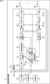
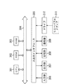
- FIG. 2 is a block diagram showing a configuration example of a wireless communication device.
- the wireless communication device 11 shown in FIG. 2 is a device that operates as an AP.
- the wireless communication device 11 is composed of a control unit 31, a power supply unit 32, a communication unit 33, and a memory unit 35.
- the communication unit 33 may be composed of two or more.
- the control unit 31 and the communication unit 33 may be configured as one or more LSIs.
- the communication unit 33 transmits and receives data.
- the communication unit 33 includes a memory unit 50, a data processing unit 51, a wireless control unit 52, a modulation / demodulation unit 53, a signal processing unit 54, a channel estimation unit 55, a wireless interface (I / F) unit 56-1 to 56-N, and It is composed of amplifier units 57-1 to 57-N.
- the communication unit 33 may be an independent component, or a part of the components of the communication unit 33 may be a common component.
- the memory unit 50, the data processing unit 51, the wireless control unit 52, and the modulation / demodulation unit 53 may be shared.
- the wireless I / F sections 56-1 to 56-N, the amplifier sections 57-1 to 57-N, and the antennas 58-1 to 58-N each have the same branch number as one set, and each set is one. It may be a component. Further, the functions of the amplifier units 57-1 to 57-N may be included in the wireless I / F units 56-1 to 56-N.
- the communication units 33-1 to 33-3 are simply referred to as communication units 33 when it is not necessary to distinguish them.
- the wireless I / F sections 56-1 to 56-N, the amplifier sections 57-1 to 57-N, and the antennas 58-1 to 58-N are simply wireless I / F sections 56 when it is not necessary to distinguish them.
- the control unit 31 is composed of a CPU (Central Processing Unit), a ROM (Read Only Memory), a RAM (Random Access Memory), and the like.
- the control unit 31 executes a program stored in ROM or the like, and controls the power supply unit 32 and the wireless control unit 52 of each communication unit 33.
- the power supply unit 32 is composed of a battery power supply or a fixed power supply, and supplies power to the entire wireless communication device 11.
- the memory unit 50 holds the data input from the upper layer and outputs it to the data processing unit 51. Further, the memory unit 50 holds the data supplied from the data processing unit 51 and outputs the data to the upper layer. A part of the memory unit 50 is arranged as the memory unit 35 in the wireless communication device 11 outside the communication unit 33.
- the data processing unit 51 At the time of transmission, the data processing unit 51 generates a packet for wireless transmission using the data supplied from the memory unit 50.
- the data processing unit 51 performs processing such as adding a header for media access control (MAC: Media Access Control) and adding an error detection code to the generated packet, and sends the processed data to the modulation / demodulation unit 53. Output.
- MAC Media Access Control
- the data processing unit 51 analyzes the MAC header, detects packet errors, reorders the data supplied from the modulation / demodulation unit 53 at the time of reception, and outputs the processed data to the memory unit 50.
- the wireless control unit 52 transfers information between each unit of the wireless communication device 11 and controls each unit in the communication unit 33.
- the wireless control unit 52 includes a transmission control unit 61 and a reception control unit 62.
- the transmission control unit 61 sets parameters in the modulation / demodulation unit 53 and the signal processing unit 54, schedules packets in the data processing unit 51, sets parameters in the wireless I / F unit 56, and the amplifier unit 57, if necessary. Performs transmission power control.
- the reception control unit 62 sets the parameters of the modulation / demodulation unit 53 and the signal processing unit 54, and sets the parameters of the wireless I / F unit 56 and the amplifier unit 57, if necessary.
- the transmission control unit 61 performs cooperative transmission of data with another AP based on the cooperative transmission start signal indicating the start of cooperative transmission received from the Master AP.
- the cooperative transmission start signal includes response setting information in which the transmission method of the transmission result of the cooperative transmission is set.
- the transmission control unit 61 determines the transmission result of cooperative transmission based on the receipt confirmation signal which is a Block Ack indicating the receipt of the data received from the STA.
- the transmission control unit 61 includes information on the receipt confirmation signal and generates a transmission result response signal indicating the determined transmission result.
- the transmission control unit 61 controls each unit so as to transmit the transmission result response signal based on the response setting information included in the cooperative transmission start signal.
- the reception control unit 62 controls each unit so as to receive the cooperative transmission start signal transmitted from the Master AP.
- the reception control unit 62 controls each unit so as to receive the receipt confirmation signal transmitted from the STA.
- the reception control unit 62 controls each unit so as to receive the cooperative transmission end signal indicating the end of the cooperative transmission transmitted from the Master AP.
- control unit 31 instead of the wireless control unit 52.
- control unit 31 and the wireless control unit 52 may be configured as one block.
- the modulation / demodulation unit 53 encodes, interleaves, and modulates the data supplied from the data processing unit 51 at the time of transmission based on the coding method and the modulation method set by the control unit 31, and performs the data symbol stream. To generate.
- the modulation / demodulation unit 53 outputs the generated data symbol stream to the signal processing unit 54.
- the modulation / demodulation unit 53 outputs the data as a result of demodulating, deinterleaving, and decoding the data symbol stream supplied from the signal processing unit 54 at the time of reception to the data processing unit 51 or the wireless control unit 52. ..
- the signal processing unit 54 performs signal processing to be subjected to spatial separation on the data symbol stream supplied from the modulation / demodulation unit 53 as necessary, and one or more transmissions obtained as a result of the signal processing.
- the symbol stream is output to each wireless I / F unit 56.
- the signal processing unit 54 performs signal processing on the received symbol stream supplied from each wireless I / F unit 56, spatially separates the stream as necessary, and data obtained as a result of the spatial separation.
- the symbol stream is output to the modulation / demodulation unit 53.
- the channel estimation unit 55 calculates the complex channel gain information of the propagation path from the preamble portion and the training signal portion of the received symbol stream supplied from each radio I / F unit 56.
- the complex channel gain information is supplied to the modulation / demodulation unit 53 and the signal processing unit 54 via the radio control unit 52, and is used for the demodulation processing in the modulation / demodulation unit 53 and the space separation processing in the signal processing unit 54.
- the wireless I / F unit 56 converts the transmission symbol stream from the signal processing unit 54 into an analog signal, performs filtering, up-conversion to a carrier frequency, and phase control, and outputs the analog signal after the phase control. Output to the amplifier section 57.
- the wireless I / F unit 56 performs phase control, down-conversion, and reverse filtering on the analog signal supplied from the amplifier unit 57, and converts the received symbol stream into a digital signal into the signal processing unit 54. And output to the channel estimation unit 55.
- the amplifier unit 57 amplifies the analog signal supplied from the wireless I / F unit 56 to a predetermined power, and outputs the amplified analog signal to the antenna 58.
- the amplifier unit 57 amplifies the analog signal supplied from the antenna 58 to a predetermined power, and outputs the amplified analog signal to the wireless I / F unit 56.
- the amplifier unit 57 may include at least a part of at least one of a transmission function and a reception function in the wireless I / F unit 56. Further, at least a part of the function of at least one of the amplifier units 57 may be a component outside the communication unit 33.
- the configuration of the wireless communication terminal 12 that operates as the STA is basically the same as that of the wireless communication device 11, the configuration of the wireless communication device 11 will be used hereafter in the description of the wireless communication terminal 12.
- the transmission control unit 61 controls to transmit the data receipt confirmation signal to AP1 and AP2.
- the reception control unit 62 controls each unit so as to receive data co-transmitted from AP1 and AP2.
- the configuration of the communication control device 13 that operates as the Master AP is basically the same as that of the wireless communication device 11, the configuration of the wireless communication device 11 will be used hereafter in the description of the communication control device 13.
- the transmission control unit 61 controls to transmit the cooperative transmission start signal to AP1 and AP2.
- the transmission control unit 61 determines whether or not the cooperative transmission is completed based on the transmission result response signals received from AP1 and AP2.
- the transmission control unit 61 controls to transmit the cooperative transmission end signal to AP1 and AP2.
- the transmission control unit 61 controls to transmit the cooperative transmission start signal of the retransmission data of the cooperative transmission.
- the reception control unit 62 controls to receive the transmission result response signal transmitted from AP1 and AP2.
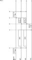
- FIG. 3 is a diagram showing a sequence for explaining a series of operations of cooperative transmission of the present technology.
- MasterAP may mutually confirm in advance whether or not they support the operation of this technology.
- the Master AP sends a Joint Tx Trigger frame to AP1 and AP2.
- the Joint Tx Trigger frame is a cooperative transmission start signal.
- ACK Scheme information is described in the Joint Tx Trigger frame.
- the ACK Scheme information is the response setting information for cooperative transmission.
- AP1 and AP2 cooperate to transmit data to STA based on the information described in the Joint Tx Trigger frame.
- the same data may be transmitted as shown in FIG. 3, or different data may be transmitted.
- BlockAck which is a data receipt confirmation signal
- the JointTxResponse frame contains information about BlockAck and shows the transmission result determined based on BlockAck.
- the predetermined time is, for example, ACK timeout.
- the Master AP that receives the Joint Tx Response frame from AP1 and AP2 determines that data retransmission is not necessary based on the Joint Tx Response frame, at time t5, the Joint Tx End frame, which is the cooperative transmission end signal, is set to AP1. And send to AP2. After transmitting the Joint Tx End frame, the sequence of cooperative transmission shown in FIG. 3 ends.
- FIG. 4 is a diagram showing a format example of the Joint Tx Trigger frame.
- the Joint Tx Trigger frame is composed of each field of SignalType, Length, TransmitDataID, TransmitScheme, TransmitResource, TransmitTime, and ACKScheme.
- the Signal Type field contains information indicating that this frame is a frame related to a request for cooperative transmission (cooperative transmission start signal).
- the Length field contains information about the length of this frame.
- TransmitDataID contains information that identifies the data that is the target of the request for cooperative transmission.
- the Transmit Scheme field contains information about the communication method used to transmit the data that is the target of the cooperative transmission request.
- the Transmit Resource field contains information about the communication resource used to transmit the data that is the target of the cooperative transmission request.
- the Transmit Time field contains information regarding the transmission timing of the data that is the target of the cooperative transmission request.
- the ACK Scheme field contains ACK Scheme information.
- the ACK Scheme information is the response setting information in which the transmission method of the information regarding the transmission result of the cooperative transmission is set between the Master AP, AP1 and AP2.
- the ACK Scheme information is, for example, information that specifies the timing for transmitting the Joint Tx Response frame, which is a transmission result response signal, to the Master AP after receiving the Block Ack from the STA.
- As the timing it is possible to specify whether to send the Joint Tx Response frame immediately (Immediate Blok) or to send after receiving the Joint Tx Response Request frame requesting the Joint Tx Response frame.
- the ACK Scheme information is also information on whether to transmit Joint Tx Response frames at the same time or in time division.
- the ACK Scheme information is further information on communication resources used by each AP when transmitting at the same time and information on the transmission timing of each AP when transmitting in a time division manner.
- the information such as the communication resource for sending the Joint Tx Response frame is the Joint from the Master AP. Described in the TxResponseRequest frame.
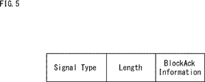
- FIG. 5 is a diagram showing a format example of the Joint Tx Response frame.
- the Joint Tx Response frame consists of Signal Type, Length, and Block ACK Information fields.
- the Signal Type field contains information indicating that this frame is a frame (transmission result response signal) containing information about Block Ack from STA.
- the Length field contains information about the length of this frame.
- the BlockACK Information field contains information about BlockAck of the cooperatively transmitted data. If Block Ack from STA could not be received, information indicating that Block Ack could not be received is described.
- AP1 and AP2 immediately transmit a Joint Tx Response frame to the Master AP after receiving the Block Ack.
- the Joint Tx Response frame is immediately transmitted to the ACK Scheme information described in the Joint Trigger of FIG. 4 using different communication resources for AP1 and AP2 at the same time. It shows the case where the information instructing is described in.
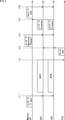
- FIG. 6 is a diagram showing another sequence of cooperative transmission of the present technology.
- FIG. 6 the information instructing the ACK Scheme information described in the Joint Trigger of FIG. 4 to be transmitted after receiving the frame requesting the Joint Tx Response from the Master AP after receiving the Block Ack from the STA. The sequence when is described is shown.
- the Master AP sends a Joint Tx Trigger frame to AP1 and AP2.
- AP1 and AP2 cooperate to transmit data to the STA based on the information described in the Joint Tx Trigger frame.
- the STA that received the data from AP1 and AP2 sends BlockAck to AP1 and AP2 at time t13.
- the Master AP sends a Joint TxResponse Request frame to AP1 and AP2.
- the Joint Tx Response Request frame is a frame in which the Master AP requests a Joint Tx Response frame containing information about Block Ack.
- AP1 and AP2 that received the Joint Tx Response Request frame transmit the Joint Tx Response frame to the Master AP at time t15 based on the ACK Scheme information described in the Joint Tx Trigger frame.
- the Master AP When the Master AP that receives the Joint Tx Response frame from AP1 and AP2 determines that data retransmission is not necessary based on the Joint Tx Response frame, it sends the Joint Tx End frame to AP1 and AP2 at time t16. After transmitting the Joint Tx End frame, the sequence of cooperative transmission shown in FIG. 6 ends.
- the Master AP may send a Joint Tx Response Request and request AP1 and AP2 to resend the Joint Tx Response.
- a transmission method different from that at the time of the previous Joint Tx Response transmission and a different communication resource may be specified.
- FIG. 7 is a diagram showing a format example of the Joint Tx Response Request frame.
- the Joint TxResponseRequest frame consists of SignalType, Length, RequestDataID, TransmitScheme, TransmitResource, and TransmitTime fields.
- the Signal Type field contains information indicating that this frame is a frame (transmission result request signal) that requests transmission of a Joint Tx Response frame from STA.
- the Length field contains information about the length of this frame.
- the RequestDataID field contains information that identifies the Ack that is the target of the transmission request.
- the Transmit Scheme field contains information about the communication method used to transmit the Response that is the target of the transmission request.
- the Transmit Resource field contains information about the communication resource used to send the Response that is the target of the transmission request.
- the Transmit Time field contains information regarding the transmission timing of the Response that is the target of the transmission request.
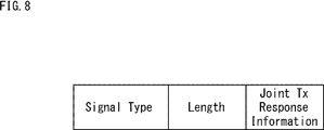
- FIG. 8 is a diagram showing a format example of the Joint Tx End frame.
- the Joint Tx End frame is composed of each field of Signal Type, Length, and Joint Tx Response Information.
- the Signal Type field contains information indicating that this frame is a frame for ending cooperative transmission (cooperative transmission end signal).
- the Length field contains information about the length of this frame.
- Joint Tx Response Information information on the transmission result of the cooperative transmission determined by the Master AP is described. If it is determined by the Joint Tx Response frame received from AP1 and AP2 that all the data has been successfully transmitted by cooperative transmission, the Joint Tx End frame with only Signal Type and Length is transmitted without including Joint Tx Response Information. You may.
- the Joint Tx Trigger frame for retransmission is transmitted.
- the Joint Tx End + Trigger frame in which the information of the Joint Tx Trigger frame is described may be transmitted.
- the Joint Tx Trigger frame sent first and the Joint Tx Trigger frame for resending may be the same.
- FIG. 9 is a flowchart illustrating the cooperative transmission process of the Master AP.
- step S11 the transmission control unit 61 controls each unit so as to transmit the Joint Tx Trigger frame.
- step S12 the transmission control unit 61 determines whether or not Immediate Block Ack is specified in the ACK Scheme information of Joint Tx Trigger. If it is determined in step S12 that Immediate Block Ack is not specified, the process proceeds to step S13.
- step S13 the transmission control unit 61 controls each unit so as to transmit a Joint TxResponseRequest frame.
- step S13 is skipped and the process proceeds to step S14.
- the AP that has received the Joint Tx Response Request frame transmits the Joint Tx Response frame (step S55 in FIG. 10 to be described later).
- step S14 the reception control unit 62 determines whether or not the Joint Tx Response frame has been received. If it is determined in step S14 that the Joint Tx Response frame has not been received, the process returns to step S13, and the subsequent processing is repeated.
- step S14 If it is determined in step S14 that the Joint Tx Response frame has been received, the process proceeds to step S15.
- step S15 the transmission control unit 61 determines whether or not retransmission is necessary. If it is determined in step S15 that retransmission is necessary, the process proceeds to step S16.
- step S16 the transmission control unit 61 transmits a frame composed of Joint Tx End and Joint Tx Trigger.
- Joint Tx Trigger is a Trigger that starts co-transmission for retransmission. After that, the process returns to step S12, and the subsequent processes are repeated.
- step S15 if the transmission control unit 61 determines that retransmission is not necessary, the transmission control unit 61 proceeds to step S17.
- step S17 the transmission control unit 61 transmits a Joint Tx End frame. After the Joint Tx End frame is transmitted, the cooperative transmission process of FIG. 9 ends.
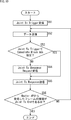
- FIG. 10 is a flowchart illustrating the cooperative transmission process of the AP.
- step S11 in FIG. 9 the reception control unit 62 controls each unit so as to receive the Joint Tx Trigger frame.
- step S52 the transmission control unit 61 controls each unit so as to transmit data in cooperation with other APs based on the Joint Tx Trigger.
- step S53 the reception control unit 62 determines whether or not Immediate Block Ack is specified in the ACK Scheme information of Joint Tx Trigger. If it is determined in step S53 that Immediate Block Ack is not specified, the process proceeds to step S54.
- the Master AP sends a Joint Tx Response Request frame (step S13 in FIG. 9).
- step S54 the reception control unit 62 controls each unit so as to receive the Joint Tx Response Request frame transmitted by the Master AP. After receiving the JointTxResponseRequest frame, the process proceeds to step S55.
- step S54 is skipped and the process proceeds to step S55.
- step S55 the transmission control unit 61 controls each unit so as to transmit the Joint Tx Response frame.
- the Master AP transmits a frame composed of the Joint Tx End frame (step S17 in FIG. 9) or the Joint Tx End and Trigger (step S16 in FIG. 9) based on the Joint Tx Response.
- step S56 the reception control unit 62 determines whether or not the type of frame received from the Master AP is a Joint Tx End frame. If it is determined in step S56 that it is not a Joint Tx End frame, there is retransmission data, so the process returns to step S52, and the subsequent processing is repeated.
- step S56 If it is determined in step S56 that it is a Joint Tx End frame, the cooperative transmission process of the AP in FIG. 10 ends.
- the first embodiment when a plurality of APs cooperate to transmit data under the control of the Master AP, if only one AP cannot receive the ACK from the STA, it is necessary to retransmit. It is possible to prevent the data without data from being retransmitted.
- Second embodiment (buffer amount is also an example of transmission)>
- each AP transmits a transmission result response signal including information on its own buffer in addition to information on Block Ack to the Master AP.
- AP transmits data to STA in cooperation as shown in FIGS. 3 and 6, receives Block Ack from STA, and transmits Joint Tx Response frame to Master AP.
- the AP when transmitting the Joint Tx Response frame to the Master AP, the AP also describes the information about its own buffer and transmits it.
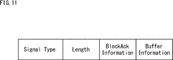
- FIG. 11 is a diagram showing a format example of the Joint Tx Response frame in the case of the second embodiment.
- the Joint TxResponse frame is composed of SignalType, Length, BlockAckInformation, and BufferInformation fields. The same part as the format example of FIG. 5 will be omitted.
- the Buffer Information field contains information about the AP's buffer.
- the information about the buffer is, for example, buffer information indicating the data held in the buffer.
- the information about the buffer is specifically information on whether the data corresponding to the information in BlockAckInformation still exists in its own buffer or has already been discarded.
- the Master AP that received the Joint Tx Response frame shown in FIG. 11 determines that it is necessary to retransmit the data from the information described in the BlockAck Information of AP1 and AP2. However, next, when the Master AP determines from Buffer Information that the data that needs to be retransmitted has already been discarded in AP1, for example, it does not request AP1 to retransmit, and the AP2 is not discarded. In order to request retransmission only for the retransmission data, Joint Tx Trigger for retransmission data is generated for AP2.
- the Master AP may handle it as follows. For example, the Master AP can describe only the information of the corresponding data in the Joint Tx Response Information of the Joint Tx End frame of FIG. 8 and discard the data from the buffer of each AP.
- the Master AP instructs each AP to retransmit data that cannot be retransmitted. Can be prevented.
- FIG. 12 is a diagram showing another sequence of cooperative transmission of the present technology.
- the Master AP transmits a Joint Tx Trigger frame to AP1 and AP2 as in the example of FIG.
- the ACK Scheme information it is not necessary to describe the transmission method of Ack, and if it is described, it is described that it is specified by STA.
- AP1 and AP2 cooperate to transmit data to STA based on the information described in the Joint Tx Trigger frame.
- the STA that received the data from AP1 and AP2 aggregates (concatenates) the Joint Tx Trigger in addition to the Block Ack, which is the response signal for confirming the receipt of the data, at time t23.
- the transmission of the Joint Tx Response frame which is the transmission result response signal, is induced for each AP.
- the ACK Scheme information states that Ack is not transmitted (No Ack).
- AP1 and AP2 transmit a Joint Tx Response frame to the Master AP at time t24 based on the ACK Scheme information described in the Joint Tx Trigger frame transmitted from the STA.
- the Master AP that receives the Joint Tx Response frame from AP1 and AP2 determines that data retransmission is not necessary based on the Joint Tx Response frame, at time t25, the Joint Tx End frame indicating the end of cooperative transmission is set to AP1. And send to AP2. After transmitting the Joint Tx End frame, the sequence of cooperative transmission shown in FIG. 12 ends.
- BlockAck may aggregate and transmit either.
- Block Ack By sending Block Ack before Joint Tx Trigger, it is possible to immediately determine the content of Joint Tx Response that AP1 and AP2 should send. On the other hand, by transmitting the Joint Tx Trigger before the Block Ack, it is possible for the surrounding communication terminals to immediately determine that the Joint Tx Response is transmitted from AP1 and AP2.
- the reception status of the Block Ack in each AP can be immediately notified to the Master AP, so that the data does not need to be resent. Can be prevented from resending.
- the Master AP controls the AP1 and AP2 to transmit the response setting information in which the transmission method of the transmission result of the cooperative transmission to the STA by AP1 and A2 is set. Therefore, it is possible to prevent the data that does not need to be resent from being resent.
- FIG. 13 is a block diagram showing a configuration example of computer hardware that executes the above-mentioned series of processes programmatically.
- the CPU Central Processing Unit
- ROM Read Only Memory
- RAM Random Access Memory
- An input / output interface 305 is further connected to the bus 304.
- An input unit 306 including a keyboard and a mouse, and an output unit 307 including a display and a speaker are connected to the input / output interface 305.
- the input / output interface 305 is connected to a storage unit 308 made of a hard disk or a non-volatile memory, a communication unit 309 made of a network interface or the like, and a drive 310 for driving the removable media 311.
- the CPU 301 loads the program stored in the storage unit 308 into the RAM 303 via the input / output interface 305 and the bus 304 and executes the program, thereby executing the series of processes described above. Is done.
- the program executed by the CPU 301 is recorded on the removable media 311 or provided via a wired or wireless transmission medium such as a local area network, the Internet, or a digital broadcast, and installed in the storage unit 308.
- the program executed by the computer may be a program that is processed in chronological order in the order described in this specification, or may be a program that is processed in parallel or at a necessary timing such as when a call is made. It may be a program in which processing is performed.
- the system means a set of a plurality of components (devices, modules (parts), etc.), and it does not matter whether all the components are in the same housing. Therefore, a plurality of devices housed in separate housings and connected via a network, and a device in which a plurality of modules are housed in one housing are both systems. ..
- this technology can have a cloud computing configuration in which one function is shared by a plurality of devices via a network and jointly processed.
- each step described in the above flowchart can be executed by one device or shared by a plurality of devices.
- one step includes a plurality of processes
- the plurality of processes included in the one step can be executed by one device or shared by a plurality of devices.
- the present technology can also have the following configurations.
- a communication unit that communicates with the first wireless communication device and the second wireless communication device, The response setting information in which the transmission method of the transmission result of the cooperative transmission to the wireless communication terminal by the first wireless communication device and the second wireless communication device is set is provided to the first wireless communication device and the second wireless communication device.
- a communication control device including a control unit that controls transmission to a wireless communication device.
- the control unit includes the response setting information, and controls the first wireless communication device and the second wireless communication device to perform the cooperative transmission to the wireless communication terminal.
- the communication control device which controls the transmission of (3)
- the control unit includes information on a receipt confirmation signal transmitted from the wireless communication terminal transmitted from the first wireless communication device and the second wireless communication device based on the response setting information, and includes the cooperation.
- the communication control device which controls reception of a transmission result response signal indicating the transmission result of transmission.
- the control unit controls whether or not to transmit the second cooperative transmission start signal to the first wireless communication device and the second wireless communication device based on the transmission result response signal.
- the communication control device according to (3) above.
- the communication control device is a receipt confirmation signal transmitted from the wireless communication terminal transmitted from the first wireless communication device and the second wireless communication device based on the response setting information, and includes the cooperation.
- the communication control device which controls reception of a transmission result response signal indicating the transmission result of transmission.
- the control unit controls
- the control unit determines that the second cooperative transmission start signal indicates the end of the cooperative transmission.
- the communication control device according to (4) above, which controls the generation and transmission of the signal.
- the control unit transmits the second cooperative transmission start signal that controls to retransmit the cooperative transmission.
- the communication control device according to (4) above.
- the control unit is based on the transmission result response signal.
- the communication control device according to (8) which controls the generation of a second cooperative transmission start signal including information indicating retransmission data to be transmitted again from the data held in the buffer.
- the control unit controls to transmit a transmission result request signal that requests the transmission result response signal.
- the communication control device according to (3) above which controls reception of the transmission result response signal transmitted from the first wireless communication device and the second wireless communication device based on the transmission result request signal.
- the control unit includes at least one of information indicating that the transmission result response signal is requested, information indicating a method of transmitting the transmission result response signal for the cooperative transmission, and radio resources used for the response.
- the communication control device according to (10) above, which controls transmission of a transmission result request signal.
- the control unit controls the transmission of the response setting information including the radio resources used by the first wireless communication device and the second wireless communication device for transmission of the transmission result response signal.
- the communication control device according to any one of (11).
- the communication control device Communicate with the first wireless communication device and the second wireless communication device, The response setting information in which the transmission method of the transmission result of the cooperative transmission to the wireless communication terminal by the first wireless communication device and the second wireless communication device is set is provided to the first wireless communication device and the second wireless communication device.
- a communication control method that controls transmission to a wireless communication device.
- a communication unit that communicates with a communication control device and other wireless communication devices, The control of receiving the cooperative transmission start signal that the communication control device controls to perform the cooperative transmission, the control of performing the cooperative transmission with the other wireless communication device to the wireless communication terminal based on the cooperative transmission start signal, and the above-mentioned
- a wireless communication device including a control unit that controls transmission of a transmission result response signal including information on a receipt confirmation signal of the wireless communication terminal for cooperative transmission to the communication control device.
- the control unit controls to receive the response setting information regarding the transmission method of the transmission result response signal from the communication control device, and transmits the transmission result response signal to the communication control device based on the response setting information.
- the wireless communication device which controls.
- the control unit controls to receive a transmission result request signal from the communication control device.
- the control unit controls to transmit the transmission result response signal indicating that the cooperative transmission has failed to the communication control device (14).
- To (16). The wireless communication device according to any one of (14) to (17), wherein the control unit controls transmission of the transmission result response signal including buffer information regarding data held in the buffer.
- the wireless communication device communicates with the communication control device and other wireless communication devices, The control of receiving the cooperative transmission start signal that the communication control device controls to perform the cooperative transmission, the control of performing the cooperative transmission with the other wireless communication device to the wireless communication terminal based on the cooperative transmission start signal, and the above-mentioned A wireless communication method for controlling transmission of a transmission result response signal including information on a receipt confirmation signal of the wireless communication terminal for cooperative transmission to the communication control device.
- a communication unit that communicates with the first wireless communication device and the second wireless communication device, For the data coordinatedly transmitted from the first wireless communication device and the second wireless communication device, the control for determining the receipt result, the receipt confirmation signal indicating the receipt result, and the information regarding the receipt confirmation signal are included.
- a wireless communication terminal including a control unit that controls transmission of control information for transmitting a transmission result response signal to the communication control device to the first wireless communication device and the second wireless communication device.
- 11 wireless communication device 12 wireless communication terminal, 13 wireless control device, 31 control unit, 32 power supply unit, 33 communication unit, 35 memory unit, 50 memory unit, 51 data processing unit, 52 wireless control unit, 53 modulation / demodulation unit, 54 Signal processing unit, 55 channel estimation unit, 56-1 to 56-N wireless I / F unit, 57-1 to 57-N amplifier unit, 58-1 to 58-N antenna
Landscapes
- Engineering & Computer Science (AREA)
- Signal Processing (AREA)
- Computer Networks & Wireless Communication (AREA)
- Mobile Radio Communication Systems (AREA)
Abstract
本技術は、再送の必要がないデータが再送されることを防ぐことができるようにする通信制御装置および方法、無線通信装置および方法、並びに無線通信端末に関する。 通信制御装置は、第1の無線通信装置および第2の無線通信装置と通信する通信部と、第1の無線通信装置および第2の無線通信装置による無線通信端末への協調送信に対する送信結果の送信方法が設定された応答設定情報を、第1の無線通信装置と第2の無線通信装置に送信する制御を行う。本技術は、通信システムに適用することができる。
Description
本技術は、通信制御装置および方法、無線通信装置および方法、並びに無線通信端末に関し、特に、再送の必要がないデータが再送されることを防ぐことができるようにした通信制御装置および方法、無線通信装置および方法、並びに無線通信端末に関する。
近年、スタジアムなどの公共施設のみならず、家庭内においてもアクセスポイント(以下、APと称する)が緻密に配置されることが増えている。このため、AP同士で協調し、システムスループットや信頼性を向上させる技術が注目を集めている。
AP間で協調する際には、AP同士を管理するAP(Master AP)が存在する場合がある。AP間協調技術の1つに、複数のAPから1台の端末(STA)に同時送信を行うJoint Transmissionがある。
Master APからの指示により、AP1およびAP2が協調送信を行う際、AP1とAP2とが協調してSTAに対してデータの送信を行う。そして、データを受信したSTAは、データの確認応答であるACKを送信する。なお、特許文献1には、ACKに基づいて変調符号化方式を制御する技術が記載されている。
STAから送信されたACKは、AP2のみで受信が完了する。AP1がACKの受信に失敗した場合、STAでデータの受信に成功し、ACKが送信されているのにもかかわらず、AP1は、データの再送を試みてしまう恐れがある。
本技術はこのような状況に鑑みてなされたものであり、再送の必要がないデータが再送されることを防ぐことができるようにするものである。
本技術の第1の側面の通信制御装置は、第1の無線通信装置および第2の無線通信装置と通信する通信部と、前記第1の無線通信装置および前記第2の無線通信装置による無線通信端末への協調送信に対する送信結果の送信方法が設定された応答設定情報を、前記第1の無線通信装置と前記第2の無線通信装置に送信する制御を行う制御部とを備える。
本技術の第2の側面の無線通信装置は、通信制御装置および他の無線通信装置と通信する通信部と、前記通信制御装置が協調送信を行うように制御する協調送信開始信号を受信する制御と、前記協調送信開始信号に基づき無線通信端末へ前記他の無線通信装置と前記協調送信を行う制御と、前記協調送信に対する前記無線通信端末の受領確認信号に関する情報を含む送信結果応答信号を前記通信制御装置へ送信する制御を行う制御部とを備える。
本技術の第3の側面の無線通信端末は、第1の無線通信装置および第2の無線通信装置と通信する通信部と、前記第1の無線通信装置および前記第2の無線通信装置から協調送信されるデータに対し、受領結果を判定する制御と、前記受領結果を示す受領確認信号とともに、前記受領確認信号に関する情報を含む送信結果応答信号を通信制御装置へと送信させるための制御情報を、前記第1の無線通信装置および前記第2の無線通信装置に送信する制御を行う制御部とを備える。
本技術の第1の側面においては、第1の無線通信装置および第2の無線通信装置と通信され、前記第1の無線通信装置および前記第2の無線通信装置による無線通信端末への協調送信に対する送信結果の送信方法が設定された応答設定情報が、前記第1の無線通信装置と前記第2の無線通信装置に送信する制御が行われる。
本技術の第2の側面においては、通信制御装置および他の無線通信装置と通信され、前記通信制御装置が協調送信を行うように制御する協調送信開始信号を受信する制御と、前記協調送信開始信号に基づき無線通信端末へ前記他の無線通信装置と前記協調送信を行う制御と、前記協調送信に対する前記無線通信端末の受領確認信号に関する情報を含む送信結果応答信号を前記通信制御装置へ送信する制御が行われる。
本技術の第3の側面においては、第1の無線通信装置および第2の無線通信装置と通信され、前記第1の無線通信装置および前記第2の無線通信装置から協調送信されるデータに対し、受領結果を判定する制御と、前記受領結果を示す受領確認信号とともに、前記受領確認信号に関する情報を含む送信結果応答信号を通信制御装置へと送信させるための制御情報を、前記第1の無線通信装置および前記第2の無線通信装置に送信する制御が行われる。
以下、本技術を実施するための形態について説明する。説明は以下の順序で行う。
0.システムおよび装置の構成例
1.第1の実施の形態(Block Ackに関する情報の送信の例)
2.第2の実施の形態(バッファ量も送信の例)
3.第3の実施の形態(STAによる送信の誘起の例)
4.第4の実施の形態(コンピュータ)
0.システムおよび装置の構成例
1.第1の実施の形態(Block Ackに関する情報の送信の例)
2.第2の実施の形態(バッファ量も送信の例)
3.第3の実施の形態(STAによる送信の誘起の例)
4.第4の実施の形態(コンピュータ)
<0.システムおよび装置の構成例>
<通信システムの構成例>
図1は、本技術の実施の形態に係る通信システムの構成例を示す図である。
<通信システムの構成例>
図1は、本技術の実施の形態に係る通信システムの構成例を示す図である。
図1の通信システムは、アクセスポイント(以下、APと称する)1およびAP2と、Master APとが、有線通信または無線通信により接続されることによって構成される。また、通信システムは、AP1およびAP2と、無線通信端末であるSTAとが、無線通信により接続されることによって構成される。
AP1およびAP2は、STAに対して、協調してデータ送信を行う無線通信装置11-1および11-2で構成される。STAは、APが管理するネットワークに属する無線通信端末12で構成される。Master APは、複数のAPの通信制御を行う通信制御装置13で構成される。無線通信装置11-1および11-2は、特に区別する必要がない場合、無線通信装置11と称する。
なお、図1における、無線通信装置の数や位置関係については一例であり、図1の記載に限定されない。
<無線通信装置の構成例>
図2は、無線通信装置の構成例を示すブロック図である。
図2は、無線通信装置の構成例を示すブロック図である。
図2に示す無線通信装置11は、APとして動作する装置である。
無線通信装置11は、制御部31、電源部32、通信部33、およびメモリ部35から構成される。通信部33は、2つ以上で構成されてもよい。制御部31および通信部33は、1つ以上のLSIとして構成されてもよい。
通信部33は、データの送信および受信を行う。通信部33は、メモリ部50、データ処理部51、無線制御部52、変復調部53、信号処理部54、チャネル推定部55、無線インタフェース(I/F)部56-1乃至56-N、およびアンプ部57-1乃至57-Nから構成される。通信部33は、独立した構成要素であってもよく、通信部33の一部の構成要素が共通化された構成要素であってもよい。例えば、メモリ部50、データ処理部51、無線制御部52、変復調部53が共通化されていてもよい。
無線I/F部56-1乃至56-N、アンプ部57-1乃至57-N、およびアンテナ58-1乃至58-Nは、同じ枝番を有するそれぞれを1組とし、各組が1つの構成要素となってもよい。また、アンプ部57-1乃至57-Nは、無線I/F部56-1乃至56-Nにその機能が内包されてもよい。
なお、以下、通信部33-1乃至33-3は、区別する必要がない場合、単に通信部33と適宜称する。また、無線I/F部56-1乃至56-N、アンプ部57-1乃至57-N、およびアンテナ58-1乃至58-Nは、区別する必要がない場合、単に無線I/F部56、アンプ部57、およびアンテナ58と適宜称する。
制御部31は、CPU(Central Processing Unit)、ROM(Read Only Memory)、RAM(Random Access Memory)などにより構成される。制御部31は、ROMなどに記憶されているプログラムを実行し、電源部32および各通信部33の無線制御部52の制御を行う。
電源部32は、バッテリー電源または固定電源で構成され、無線通信装置11の全体に対して電力を供給する。
メモリ部50は、上位層から入力されたデータを保持し、データ処理部51へと出力する。また、メモリ部50は、データ処理部51から供給されるデータを保持し、上位層へと出力する。メモリ部50の一部は、メモリ部35として、通信部33外の無線通信装置11に配置される。
データ処理部51は、送信時、メモリ部50から供給されるデータを用いて無線送信のためのパケットを生成する。データ処理部51は、生成したパケットに対して、メディアアクセス制御(MAC : Media Access Control)のためのヘッダの付加や誤り検出符号の付加などの処理を行い、処理後のデータを変復調部53に出力する。
データ処理部51は、受信時、変復調部53から供給されるデータに対して、MACヘッダの解析、パケット誤りの検出、リオーダ処理などを行い、処理後のデータをメモリ部50に出力する。
無線制御部52は、無線通信装置11の各部の間の情報の受け渡しを行い、通信部33内の各部を制御する。無線制御部52は、送信制御部61と受信制御部62とからなる。
送信制御部61は、送信時、必要に応じて、変復調部53および信号処理部54におけるパラメータ設定、データ処理部51におけるパケットのスケジューリング、無線I/F部56、およびアンプ部57のパラメータ設定や送信電力制御を行う。受信制御部62は、受信時、必要に応じて、変復調部53および信号処理部54におけるパラメータ設定、無線I/F部56、およびアンプ部57のパラメータ設定を行う。
また、特に、送信制御部61は、Master APから受信された協調送信の開始を示す協調送信開始信号に基づいて、他のAPとデータの協調送信を行う。協調送信開始信号には、協調送信の送信結果の送信方法が設定された応答設定情報が含まれる。
送信制御部61は、STAから受信されたデータの受領を示すBlock Ackである受領確認信号に基づいて、協調送信の送信結果を判定する。送信制御部61は、受領確認信号に関する情報を含み、判定した送信結果を示す送信結果応答信号を生成する。送信制御部61は、協調送信開始信号に含まれる応答設定情報に基づいて、送信結果応答信号を送信するように各部を制御する。
受信制御部62は、Master APから送信されてくる協調送信開始信号を受信するように各部を制御する。受信制御部62は、STAから送信されてくる受領確認信号を受信するように各部を制御する。受信制御部62は、Master APから送信されてくる協調送信の終了を示す協調送信終了信号を受信するように各部を制御する。
なお、これらの無線制御部52の少なくとも一部の動作は、無線制御部52の代わりに制御部31により行われるようにしてもよい。また、制御部31および無線制御部52は、1つのブロックとして構成されてもよい。
変復調部53は、送信時、データ処理部51から供給されるデータに対し、制御部31によって設定された符号化方式および変調方式に基づいて、符号化、インターリーブ、および変調を行い、データシンボルストリームを生成する。変復調部53は、生成したデータシンボルストリームを信号処理部54に出力する。
変復調部53は、受信時、信号処理部54から供給されるデータシンボルストリームに対して、復調、デインターリーブ、および復号を行った結果のデータを、データ処理部51または無線制御部52に出力する。
信号処理部54は、送信時、必要に応じて、変復調部53から供給されるデータシンボルストリームに対して、空間分離に供される信号処理を行い、信号処理の結果得られる1つ以上の送信シンボルストリームをそれぞれの無線I/F部56に出力する。
信号処理部54は、受信時、それぞれの無線I/F部56から供給される受信シンボルストリームに対して信号処理を行い、必要に応じてストリームの空間分離を行い、空間分離の結果得られるデータシンボルストリームを変復調部53に出力する。
チャネル推定部55は、それぞれの無線I/F部56から供給される受信シンボルストリームのうち、プリアンブル部分およびトレーニング信号部分から伝搬路の複素チャネル利得情報を算出する。複素チャネル利得情報は、無線制御部52を介して、変復調部53と信号処理部54に供給され、変復調部53における復調処理および信号処理部54における空間分離処理に用いられる。
無線I/F部56は、送信時、信号処理部54からの送信シンボルストリームをアナログ信号に変換し、フィルタリング、搬送波周波数へのアップコンバート、および位相制御を行い、位相制御の後のアナログ信号をアンプ部57に出力する。
無線I/F部56は、受信時、アンプ部57から供給されるアナログ信号に対して、位相制御、ダウンコンバード、逆フィルタリングを行い、デジタル信号に変換した結果の受信シンボルストリームを信号処理部54およびチャネル推定部55に出力する。
アンプ部57は、送信時、無線I/F部56から供給されるアナログ信号を所定の電力まで増幅し、電力を増幅したアナログ信号をアンテナ58に出力する。アンプ部57は、受信時、アンテナ58から供給されるアナログ信号を所定の電力まで増幅し、電力を増幅したアナログ信号を無線I/F部56に出力する。
アンプ部57は、送信時の機能と受信時の機能との少なくともどちらか一方の、少なくとも一部が無線I/F部56に内包されていてもよい。また、アンプ部57の少なくともどちらか一方の機能の少なくとも一部が通信部33外の構成要素となってもよい。
なお、STAとして動作する無線通信端末12の構成も、無線通信装置11と基本的に同様の構成であるため、以降、無線通信端末12の説明に、無線通信装置11の構成が用いられる。
この場合、送信制御部61は、データの受領確認信号を、AP1およびAP2に送信する制御を行う。受信制御部62は、AP1およびAP2から協調送信されるデータを受信するように各部を制御する。
また、Master APとして動作する通信制御装置13の構成も、無線通信装置11と基本的に同様の構成であるため、以降、通信制御装置13の説明に、無線通信装置11の構成が用いられる。
この場合、送信制御部61は、AP1およびAP2に、協調送信開始信号を送信する制御を行う。送信制御部61は、AP1およびAP2から受信された送信結果応答信号に基づいて、協調送信が完了したか否かを判定する。送信制御部61は、協調送信が完了した場合、協調送信終了信号をAP1およびAP2に送信する制御を行う。なお、送信制御部61は、協調送信が完了していない場合、協調送信の再送データの協調送信開始信号を送信する制御を行う。
受信制御部62は、AP1およびAP2から送信されてくる送信結果応答信号を受信する制御を行う。
<1.第1の実施の形態(Block Ackに関する情報の送信の例)>
まず、第1の実施の形態として、各APがMaster APに対し、Block Ackに関する情報を含む送信結果応答信号を送信する例について説明する。
まず、第1の実施の形態として、各APがMaster APに対し、Block Ackに関する情報を含む送信結果応答信号を送信する例について説明する。
<本技術の協調送信のシーケンス例>
図3は、本技術の協調送信の一連の動作について説明するシーケンスを示す図である。
図3は、本技術の協調送信の一連の動作について説明するシーケンスを示す図である。
なお、Master AP,AP1,AP2,STAは、互いに、本技術の動作に対応しているか否かを事前に確認しておいてもよい。
時刻t1において、Master APは、Joint Tx TriggerフレームをAP1およびAP2に送信する。Joint Tx Triggerフレームは、協調送信開始信号である。本技術において、Joint Tx Triggerフレームには、ACK Scheme情報が記載されている。ACK Scheme情報は、協調送信に対する応答設定情報である。
時刻t2において、AP1およびAP2は、Joint Tx Triggerフレームに記載された情報に基づいて、STAに対して協調してデータを送信する。このとき、AP1およびAP2が送信するデータは、図3のように同一のデータを送信してもよいし、異なるデータを送信してもよい。
AP1およびAP2からのデータを受信したSTAは、時刻t3において、データの受領確認信号であるBlock Ackを、AP1およびAP2に送信する。
所定の時間内にSTAからのBlock Ackを受信したAP1とAP2は、時刻t4において、Joint Tx TriggerフレームのACK Scheme情報に基づいて、送信結果応答信号であるJoint Tx ResponseフレームをMaster APに送信する。Joint Tx Response フレームは、Block Ackに関する情報を含み、Block Ackに基づいて判定された送信結果を示す。所定の時間とは、例えば、ACKtimeoutである。
AP1およびAP2からJoint Tx Responseフレームを受信したMaster APは、Joint Tx Responseフレームに基づいて、データの再送が必要ないと判定した場合、時刻t5において、協調送信終了信号であるJoint Tx EndフレームをAP1およびAP2に送信する。Joint Tx Endフレームの送信後、図3の協調送信のシーケンスは終了となる。
<Joint Tx Trigger フレームのフォーマット例>
図4は、Joint Tx Trigger フレームのフォーマット例を示す図である。
図4は、Joint Tx Trigger フレームのフォーマット例を示す図である。
図4において、Joint Tx Trigger フレームは、Signal Type、Length、Transmit Data ID、Transmit Scheme、Transmit Resource、Transmit Time、ACK Schemeの各fieldからなる。
Signal Typeのfieldには、このフレームが協調送信の要求に関するフレーム(協調送信開始信号)であることを示す情報が含まれる。
Lengthのfieldには、このフレームの長さに関する情報が含まれる。
Transmit Data IDのfieldには、協調送信の要求の対象となるデータを識別する情報が含まれる。
Transmit Schemeのfieldには、協調送信の要求の対象となるデータの送信に用いる通信方式に関する情報が含まれる。
Transmit Resourceのfieldには、協調送信の要求の対象となるデータの送信に用いる通信リソースに関する情報が含まれる。
Transmit Timeのfieldには、協調送信の要求の対象となるデータの送信タイミングに関する情報が含まれる。
ACK Schemeのfieldには、ACK Scheme情報が含まれる。ACK Scheme情報は、上述したように、Master AP,AP1,AP2の間で協調送信の送信結果に関する情報の送信方法が設定された応答設定情報である。
ACK Scheme情報は、例えば、STAからのBlock Ackを受信後、Master APに対して送信結果応答信号であるJoint Tx Responseフレームを送信するタイミングを指定する情報である。タイミングとしては、Joint Tx Responseフレームを、すぐに送信するか(Immediate Blok)、または、Joint Tx Responseフレームを要求するJoint Tx Response Requestフレームを受信してから送信するかなどが指定可能である。
ACK Scheme情報は、また、Joint Tx Responseフレームを同時に送信するか、時分割で送信するかの情報である。
ACK Scheme情報は、さらに、同時に送信する際に、各APが使用する通信リソース情報や時分割で送信する際の各APの送信タイミングに関する情報である。
なお、Master APから送信されるJoint Tx Response Requestフレームを受信してから、Joint Tx Responseフレームを送信するよう指示する場合、Joint Tx Responseフレームを送信する通信リソースなどの情報は、Master APからのJoint Tx Response Requestフレームに記載される。
<Joint Tx Responseフレームのフォーマット例>
図5は、Joint Tx Responseフレームのフォーマット例を示す図である。
図5は、Joint Tx Responseフレームのフォーマット例を示す図である。
図5において、Joint Tx Responseフレームは、Signal Type、Length、BlockACK Informationの各fieldからなる。
Signal Typeのfieldには、このフレームがSTAからのBlock Ackに関する情報を含むフレーム(送信結果応答信号)であることを示す情報が含まれる。
Lengthのfieldには、このフレームの長さに関する情報が含まれる。
BlockACK Informationのfieldには、協調送信したデータのBlock Ackに関する情報が含まれる。STAからのBlock Ackを受信できなかった場合、Block Ackが受信できなかったことを示す情報が記載される。
ここで、図3のシーケンスでは、AP1とAP2は、Block Ackを受信後、Master APに対してJoint Tx Responseフレームをすぐに送信する。図3のシーケンスは、図4のJoint Triggerに記載されたACK Scheme情報に、STAからのBlock Ackを受信後、AP1とAP2で同時に異なる通信リソースを用いてJoint Tx Responseフレームをすぐに送信するように指示する情報が記載されている場合が示されたものである。
<本技術の協調送信の他のシーケンス例>
図6は、本技術の協調送信の他のシーケンスを示す図である。
図6は、本技術の協調送信の他のシーケンスを示す図である。
図6においては、図4のJoint Triggerに記載されたACK Scheme情報にSTAからのBlock Ackを受信後、Master APからのJoint Tx Responseを要求するフレームを受信してから送信するように指示する情報が記載されている場合のシーケンスが示されている。
時刻t11において、Master APは、Joint Tx TriggerフレームをAP1およびAP2に送信する。
時刻t12において、AP1およびAP2は、Joint Tx Triggerフレームに記載された情報に基づいて、STAに対して協調してデータを送信する。
AP1およびAP2からのデータを受信したSTAは、時刻t13において、Block Ackを、AP1およびAP2に送信する。
時刻t14において、Master APは、Joint Tx Response RequestフレームをAP1およびAP2に送信する。Joint Tx Response Requestフレームは、Master APが、Block Ackに関する情報を含むJoint Tx Responseフレームを要求するフレームである。
Joint Tx Response Requestフレームを受信したAP1とAP2は、時刻t15において、Joint Tx Triggerフレームに記載されたACK Scheme情報に基づいて、Joint Tx ResponseフレームをMaster APに送信する。
AP1およびAP2からJoint Tx Responseフレームを受信したMaster APは、Joint Tx Responseフレームに基づいて、データの再送が必要ないと判定した場合、時刻t16において、Joint Tx EndフレームをAP1およびAP2に送信する。Joint Tx Endフレームの送信後、図6の協調送信のシーケンスは終了となる。
AP1およびAP2のいずれからもJoint Tx Responseを受信できなかった場合、Master APは、Joint Tx Response Requestを送信し、AP1とAP2にJoint Tx Responseの再送を要求してもよい。その際、前回のJoint Tx Response送信時とは異なる送信方法、異なる通信リソースを指定してもよい。
<Joint Tx Response Requestフレームのフォーマット例>
図7は、Joint Tx Response Requestフレームのフォーマット例を示す図である。
図7は、Joint Tx Response Requestフレームのフォーマット例を示す図である。
図7において、Joint Tx Response Requestフレームは、Signal Type、Length、Request Data ID、Transmit Scheme、Transmit Resource、Transmit Timeの各fieldからなる。
Signal Typeのfieldには、このフレームがSTAからのJoint Tx Responseフレームの送信を要求するフレーム(送信結果要求信号)であることを示す情報が含まれる。
Lengthのfieldには、このフレームの長さに関する情報が含まれる。
Request Data IDのfieldには、送信要求の対象となるAckを識別する情報が含まれる。
Transmit Schemeのfieldには、送信要求の対象となるResponseの送信に用いる通信方式に関する情報が含まれる。
Transmit Resourceのfieldには、送信要求の対象となるResponseの送信に用いる通信リソースに関する情報が含まれる。
Transmit Timeのfieldには、送信要求の対象となるResponseの送信のタイミングに関する情報が含まれる。
<Joint Tx Endフレームのフォーマット例>
図8は、Joint Tx Endフレームのフォーマット例を示す図である。
図8は、Joint Tx Endフレームのフォーマット例を示す図である。
図8において、Joint Tx Endフレームは、Signal Type、Length、Joint Tx Response Informationの各fieldからなる。
Signal Typeのfieldには、このフレームが協調送信を終了するフレーム(協調送信終了信号)であることを示す情報が含まれる。
Lengthのfieldには、このフレームの長さに関する情報が含まれる。
Joint Tx Response Informationのfieldには、Master APが判定した協調送信の送信結果に関する情報が記載される。AP1,AP2から受信したJoint Tx Responseフレームによりすべてのデータが協調送信により送信成功していると判定された場合、Joint Tx Response Informationを含めず、Signal Type、LengthのみのJoint Tx Endフレームが送信されてもよい。
Joint Tx Endフレームを送信することにより、従来で述べたように、AP1がSTAからのBlock Ackの受信に失敗し、AP2のみがSTAからのBlock Ackを受信した場合でもAP1に協調送信の送信結果が通知される。したがって、AP1が、再送が必要だと判定し、データを再送してしまうことを防ぐことができる。また、再送のために、AP1のバッファに残されているデータも削除することができる。
AP1およびAP2からJoint Tx Responseフレームを受信したMaster APが、そのBlock Ackに関する情報によりデータの再送が必要だと判定した場合、再送用のJoint Tx Triggerフレームが送信される。その際、Joint Tx End フレームの情報に加え、Joint Tx Triggerフレームの情報を記載したJoint Tx End + Triggerフレームを送信してもよい。なお、すべてのデータを再送する場合、最初に送付したJoint Tx Triggerフレームと再送用のJoint Tx Triggerフレームとは同じであってもよい。
一方、再送が必要ではないと判定された場合、Joint Tx Triggerフレームを送信せずに、Joint Tx Endのみが送信される。
<Master APの動作例>
図9は、Master APの協調送信処理について説明するフローチャートである。
図9は、Master APの協調送信処理について説明するフローチャートである。
ステップS11において、送信制御部61は、Joint Tx Triggerフレームを送信するように各部を制御する。
ステップS12において、送信制御部61は、Joint Tx TriggerのACK Scheme情報において、Immediate Block Ackを指定しているか否かを判定する。Immediate Block Ackを指定していないと、ステップS12において判定された場合、処理は、ステップS13に進む。
ステップS13において、送信制御部61は、Joint Tx Response Requestフレームを送信するように各部を制御する。
ステップS12において、Immediate Block Ackを指定していると判定された場合、ステップS13をスキップし、処理は、ステップS14に進む。
Joint Tx Response Requestフレームを受信したAPは、Joint Tx Responseフレームを送信してくる(後述する図10のステップS55)。
ステップS14において、受信制御部62は、Joint Tx Responseフレームを受信したか否かを判定する。Joint Tx Responseフレームを受信していないと、ステップS14において判定された場合、ステップS13に戻り、それ以降の処理が繰り返される。
ステップS14において、Joint Tx Responseフレームを受信したと判定された場合、処理は、ステップS15に進む。
ステップS15において、送信制御部61は、再送が必要であるか否かを判定する。再送が必要であると、ステップS15において判定された場合、処理は、ステップS16に進む。
ステップS16において、送信制御部61は、Joint Tx EndとJoint Tx Triggerとからなるフレームとを送信する。この場合、Joint Tx Triggerは、再送用の協調送信を開始するTriggerである。その後、ステップS12に戻り、それ以降の処理が繰り返される。
ステップS15において、送信制御部61は、再送が必要ではないと判定された場合、ステップS17に進む。
ステップS17において、送信制御部61は、Joint Tx Endフレームを送信する。Joint Tx Endフレームの送信後、図9の協調送信処理は終了となる。
<APの動作例>
図10は、APの協調送信処理について説明するフローチャートである。
図10は、APの協調送信処理について説明するフローチャートである。
Master APは、Joint Tx Triggerフレームを送ってくる(図9のステップS11)。ステップS51において、受信制御部62は、Joint Tx Triggerフレームを受信するように各部を制御する。
ステップS52において、送信制御部61は、Joint Tx Triggerに基づいて、他のAPと協調して、データを送信するように各部を制御する。
ステップS53において、受信制御部62は、Joint Tx TriggerのACK Scheme情報で、Immediate Block Ackが指定されているか否かを判定する。Immediate Block Ackが指定されていないと、ステップS53において判定された場合、処理は、ステップS54に進む。
Immediate Block Ackが指定されていない場合、Master APがJoint Tx Response Requestフレームを送信してくる(図9のステップS13)。
ステップS54において、受信制御部62は、Master APにより送信されたJoint Tx Response Requestフレームを受信するように各部を制御する。Joint Tx Response Requestフレームの受信後、処理は、ステップS55に進む。
また、ステップS53において、Immediate Block Ackが指定されていると判定された場合、ステップS54をスキップし、処理は、ステップS55に進む。
ステップS55において、送信制御部61は、Joint Tx Responseフレームを送信するように各部を制御する。
その後、Master APは、Joint Tx Responseに基づいて、Joint Tx End フレーム(図9のステップS17)またはJoint Tx EndとTrigger(図9のステップS16)とからなるフレームを送信してくる。
ステップS56において、受信制御部62は、Master APから受信したフレームの種類が、Joint Tx Endフレームであるか否かを判定する。Joint Tx Endフレームではないと、ステップS56において判定された場合、再送データがあるので、ステップS52に戻り、それ以降の処理が繰り返される。
ステップS56において、Joint Tx Endフレームであると判定された場合、図10のAPの協調送信処理は終了となる。
以上のように、第1の実施の形態においては、Master APの制御により複数のAPが協調してデータ送信を行う際、あるAPのみSTAからのACKを受信できなかった場合など、再送の必要のないデータが再送されることを防ぐことができる。
<2.第2の実施の形態(バッファ量も送信の例)>
次に、第2の実施の形態として、各APがMaster APに対し、Block Ackに関する情報に加えて、自身のバッファの情報を含む送信結果応答信号を送信する例について説明する。
次に、第2の実施の形態として、各APがMaster APに対し、Block Ackに関する情報に加えて、自身のバッファの情報を含む送信結果応答信号を送信する例について説明する。
APは、Master APの指示により、図3や図6のようにSTAに対して協調してデータ送信を行い、STAからBlock Ackを受信し、Master APにJoint Tx Responseフレームを送信する。第2の実施の形態においては、Master APにJoint Tx Responseフレームを送信する際に、APは、自身のバッファについての情報も記載して送信する。
<Joint Tx Responseフレームのフォーマット例>
図11は、第2の実施の形態の場合のJoint Tx Responseフレームのフォーマット例を示す図である。
図11は、第2の実施の形態の場合のJoint Tx Responseフレームのフォーマット例を示す図である。
図11において、Joint Tx Response フレームは、Signal Type、Length、BlockAck Information、およびBuffer Informationの各fieldからなる。なお、図5のフォーマット例と同じ部分については、説明を省略する。
Buffer Informationのfieldには、APのバッファについての情報が含まれる。バッファについての情報は、例えば、バッファに保持されているデータを示すバッファ情報である。バッファについての情報は、具体的には、BlockAck Information内の情報に対応するデータが自身のバッファ内にまだ存在しているか、すでに破棄されているかの情報である。
図11に示されるJoint Tx Responseフレームを受信したMaster APは、AP1,AP2のBlockAck Informationに記載された情報からデータの再送が必要だと判定する。しかしながら、次に、Master APは、Buffer Informationから、再送が必要なデータが、例えば、AP1ではすでに破棄されていると判定した場合、AP1に対して再送は要求せず、破棄されていないAP2に対してのみ再送を要求するために、AP2に対して、再送データ用のJoint Tx Triggerを生成する。
また、再送が必要ではないが、いずれかのAPのバッファにデータが残っている場合、Master APは、次のように対応するようにしてもよい。例えば、Master APは、図8のJoint Tx EndフレームのJoint Tx Response Informationにて該当するデータの情報のみを記載して、各APのバッファから、データを破棄させることができる。
以上の第2の実施の形態においては、各APで、再送上限に達するなどしてパケットを破棄していた場合などに、Master APが各APに対して再送できないデータの再送を指示することを防ぐことができる。
<3.第3の実施の形態(STAによる送信の誘起の例)>
次に、第3の実施の形態として、STAが各APにMaster APに対する送信結果応答信号の送信を誘起する例について説明する。
次に、第3の実施の形態として、STAが各APにMaster APに対する送信結果応答信号の送信を誘起する例について説明する。
<本技術の協調送信のシーケンス例>
図12は、本技術の協調送信の他のシーケンスを示す図である。
図12は、本技術の協調送信の他のシーケンスを示す図である。
時刻t21において、Master APは、図3の例と同様に、Joint Tx TriggerフレームをAP1およびAP2に送信する。このとき、ACK Scheme情報では、Ackの送信方法については記載しなくてもよく、記載する場合は、STAによって指定される旨を記載する。
時刻t22において、AP1およびAP2は、Joint Tx Triggerフレームに記載された情報に基づいて、STAに対して協調してデータを送信する。
AP1およびAP2からのデータを受信したSTAは、時刻t23において、データの受領確認の応答信号であるBlock Ackに加えて、Joint Tx Triggerをアグリゲート(連結)して送信する。これにより、各APに対して、送信結果応答信号であるJoint Tx Responseフレームの送信が誘起される。このとき、ACK Scheme情報にはAckを送信しない旨(No Ack)が記載される。
AP1とAP2は、時刻t24において、STAから送信されたJoint Tx Triggerフレームに記載されたACK Scheme情報に基づいて、Joint Tx ResponseフレームをMaster APに送信する。
AP1およびAP2からJoint Tx Responseフレームを受信したMaster APは、Joint Tx Responseフレームに基づいて、データの再送が必要ないと判定した場合、時刻t25において、協調送信の終了を示すJoint Tx EndフレームをAP1およびAP2に送信する。Joint Tx Endフレームの送信後、図12の協調送信のシーケンスは終了となる。
なお、上述した時刻t23において、Block AckとJoint Tx Triggerは、どちらを先にアグリゲートして送信してもよい。
Joint Tx TriggerよりもBlock Ackを先に送信することで、AP1,AP2が送信すべきJoint Tx Responseの内容を直ちに判定することができる。一方、Block AckよりもJoint Tx Triggerを先に送信することで、周囲の通信端末がAP1,AP2からJoint Tx Responseが送信されることを直ちに判定することができる。
以上の第3の実施の形態においては、Block AckともにJoint Tx Triggerが送られるので、各APにおけるBlock Ackの受信状況を、Master APに即座に通知することができるので、再送する必要のないデータを再送することを防ぐことができる。
以上のように、本技術においては、Master APが、AP1およびA2によるSTAへの協調送信の送信結果の送信方法が設定された応答設定情報を、AP1とAP2に送信する制御を行うようにしたので、再送する必要のないデータを再送することを防ぐことができる。
<4.第4の実施の形態(コンピュータ)>
<コンピュータの構成例>
上述した一連の処理は、ハードウェアにより実行することもできるし、ソフトウェアにより実行することもできる。一連の処理をソフトウェアにより実行する場合には、そのソフトウェアを構成するプログラムが、専用のハードウェアに組み込まれているコンピュータ、または汎用のパーソナルコンピュータなどに、プログラム記録媒体からインストールされる。
<コンピュータの構成例>
上述した一連の処理は、ハードウェアにより実行することもできるし、ソフトウェアにより実行することもできる。一連の処理をソフトウェアにより実行する場合には、そのソフトウェアを構成するプログラムが、専用のハードウェアに組み込まれているコンピュータ、または汎用のパーソナルコンピュータなどに、プログラム記録媒体からインストールされる。
図13は、上述した一連の処理をプログラムにより実行するコンピュータのハードウェアの構成例を示すブロック図である。
CPU(Central Processing Unit)301、ROM(Read Only Memory)302、RAM(Random Access Memory)303は、バス304により相互に接続されている。
バス304には、さらに、入出力インタフェース305が接続されている。入出力インタフェース305には、キーボード、マウスなどよりなる入力部306、ディスプレイ、スピーカなどよりなる出力部307が接続される。また、入出力インタフェース305には、ハードディスクや不揮発性のメモリなどよりなる記憶部308、ネットワークインタフェースなどよりなる通信部309、リムーバブルメディア311を駆動するドライブ310が接続される。
以上のように構成されるコンピュータでは、CPU301が、例えば、記憶部308に記憶されているプログラムを入出力インタフェース305及びバス304を介してRAM303にロードして実行することにより、上述した一連の処理が行われる。
CPU301が実行するプログラムは、例えばリムーバブルメディア311に記録して、あるいは、ローカルエリアネットワーク、インターネット、デジタル放送といった、有線または無線の伝送媒体を介して提供され、記憶部308にインストールされる。
なお、コンピュータが実行するプログラムは、本明細書で説明する順序に沿って時系列に処理が行われるプログラムであっても良いし、並列に、あるいは呼び出しが行われたとき等の必要なタイミングで処理が行われるプログラムであっても良い。
なお、本明細書において、システムとは、複数の構成要素(装置、モジュール(部品)等)の集合を意味し、すべての構成要素が同一筐体中にあるか否かは問わない。したがって、別個の筐体に収納され、ネットワークを介して接続されている複数の装置、及び、1つの筐体の中に複数のモジュールが収納されている1つの装置は、いずれも、システムである。
また、本明細書に記載された効果はあくまで例示であって限定されるものでは無く、また他の効果があってもよい。
本技術の実施の形態は、上述した実施の形態に限定されるものではなく、本技術の要旨を逸脱しない範囲において種々の変更が可能である。
例えば、本技術は、1つの機能を、ネットワークを介して複数の装置で分担、共同して処理するクラウドコンピューティングの構成をとることができる。
また、上述のフローチャートで説明した各ステップは、1つの装置で実行する他、複数の装置で分担して実行することができる。
さらに、1つのステップに複数の処理が含まれる場合には、その1つのステップに含まれる複数の処理は、1つの装置で実行する他、複数の装置で分担して実行することができる。
<構成の組み合わせ例>
本技術は、以下のような構成をとることもできる。
(1)
第1の無線通信装置および第2の無線通信装置と通信する通信部と、
前記第1の無線通信装置および前記第2の無線通信装置による無線通信端末への協調送信の送信結果の送信方法が設定された応答設定情報を、前記第1の無線通信装置と前記第2の無線通信装置に送信する制御を行う制御部と
を備える通信制御装置。
(2)
前記制御部は、前記応答設定情報を含み、前記第1の無線通信装置と前記第2の無線通信装置が前記無線通信端末への前記協調送信を行うように制御する第1の協調送信開始信号を送信する制御を行う
前記(1)に記載の通信制御装置。
(3)
前記制御部は、前記応答設定情報に基づいて前記第1の無線通信装置と前記第2の無線通信装置から送信された、前記無線通信端末から送信された受領確認信号に関する情報を含み、前記協調送信の前記送信結果を示す送信結果応答信号を受信する制御を行う
前記(1)および(2)に記載の通信制御装置。
(4)
前記制御部は、前記送信結果応答信号に基づいて、前記第1の無線通信装置と前記第2の無線通信装置に対し、第2の協調送信開始信号を送信するか否かを判定する制御を行う
前記(3)に記載の通信制御装置。
(5)
前記制御部は、前記送信結果応答信号に基づいて、前記第2の協調送信開始信号を送信しないと判定した場合、前記協調送信の終了を示す協調送信終了信号を送信する制御を行う
前記(4)に記載の通信制御装置。
(6)
前記送信結果応答信号に基づいて、前記第2の協調送信開始信号を送信すると判定した場合、前記制御部は、前記第2の協調送信開始信号が、前記協調送信の終了を示す協調送信終了信号を含むよう生成し、送信する制御を行う
前記(4)に記載の通信制御装置。
(7)
前記制御部は、前記送信結果応答信号に基づいて、前記第2の協調送信開始信号を送信すると判定した場合、前記協調送信の再送を行うように制御する前記第2の協調送信開始信号を送信する制御を行う
前記(4)に記載の通信制御装置。
(8)
前記制御部は、前記送信結果応答信号の送信方法を示す前記応答設定情報を送信する制御を行う
(3)乃至(7)のいずれかに記載の通信制御装置。
(9)
前記制御部は、前記送信結果応答信号が前記第1の無線通信装置または前記第2の無線通信装置のバッファに保持されているデータに関するバッファ情報を含む場合、前記送信結果応答信号に基づいて、前記バッファに保持されている前記データの中から再度送信する再送データを示す情報を含む第2の協調送信開始信号を生成する制御を行う
(8)に記載の通信制御装置。
(10)
前記制御部は、前記送信結果応答信号を要求する送信結果要求信号を送信する制御を行い、
前記送信結果要求信号に基づいて前記第1の無線通信装置および前記第2の無線通信装置から送信された、前記送信結果応答信号を受信する制御を行う
前記(3)に記載の通信制御装置。
(11)
前記制御部は、前記送信結果応答信号を要求することを示す情報、前記協調送信に対する前記送信結果応答信号の送信方法を示す情報、または応答に利用する無線資源のうち、少なくとも一つを含む前記送信結果要求信号を送信する制御を行う
前記(10)に記載の通信制御装置。
(12)
前記制御部は、前記第1の無線通信装置および前記第2の無線通信装置が前記送信結果応答信号の送信に利用する無線資源を含む前記応答設定情報を送信する制御を行う
前記(3)乃至(11)のいずれかに記載の通信制御装置。
(13)
通信制御装置が、
第1の無線通信装置および第2の無線通信装置と通信し、
前記第1の無線通信装置および前記第2の無線通信装置による無線通信端末への協調送信の送信結果の送信方法が設定された応答設定情報を、前記第1の無線通信装置と前記第2の無線通信装置に送信する制御を行う
通信制御方法。
(14)
通信制御装置および他の無線通信装置と通信する通信部と、
前記通信制御装置が協調送信を行うように制御する協調送信開始信号を受信する制御と、前記協調送信開始信号に基づき無線通信端末へ前記他の無線通信装置と前記協調送信を行う制御と、前記協調送信に対する前記無線通信端末の受領確認信号に関する情報を含む送信結果応答信号を前記通信制御装置へ送信する制御を行う制御部と
を備える無線通信装置。
(15)
前記制御部は、前記通信制御装置より前記送信結果応答信号の送信方法に関する応答設定情報を受信する制御を行い、前記応答設定情報に基づいて、前記送信結果応答信号を前記通信制御装置に送信する制御を行う
前記(14)に記載の無線通信装置。
(16)
前記制御部は、前記通信制御装置より送信結果要求信号を受信する制御を行い、
前記送信結果要求信号に基づいて、前記送信結果応答信号を前記通信制御装置に送信する制御を行う
前記(14)または(15)に記載の無線通信装置。
(17)
前記制御部は、前記無線通信端末より前記受領確認信号を受信しなかった場合、前記協調送信が失敗したことを示す前記送信結果応答信号を、前記通信制御装置へ送信する制御を行う
前記(14)乃至(16)のいずれかに記載の無線通信装置。
(18)
前記制御部は、バッファに保持しているデータに関するバッファ情報を含む前記送信結果応答信号を送信する制御を行う
前記(14)乃至(17)のいずれかに記載の無線通信装置。
(19)
無線通信装置が
通信制御装置および他の無線通信装置と通信し、
前記通信制御装置が協調送信を行うように制御する協調送信開始信号を受信する制御と、前記協調送信開始信号に基づき無線通信端末へ前記他の無線通信装置と前記協調送信を行う制御と、前記協調送信に対する前記無線通信端末の受領確認信号に関する情報を含む送信結果応答信号を前記通信制御装置へ送信する制御を行う
無線通信方法。
(20)
第1の無線通信装置および第2の無線通信装置と通信する通信部と、
前記第1の無線通信装置および前記第2の無線通信装置から協調送信されるデータに対し、受領結果を判定する制御と、前記受領結果を示す受領確認信号とともに、前記受領確認信号に関する情報を含む送信結果応答信号を通信制御装置へと送信させるための制御情報を、前記第1の無線通信装置および前記第2の無線通信装置に送信する制御を行う制御部と
を備える無線通信端末。
11 無線通信装置, 12 無線通信端末,13 無線制御装置, 31 制御部, 32 電源部, 33 通信部,35 メモリ部, 50 メモリ部, 51 データ処理部, 52 無線制御部, 53 変復調部, 54 信号処理部, 55 チャネル推定部, 56-1乃至56-N 無線I/F部, 57-1乃至57-N アンプ部,58-1乃至58-N アンテナ
Claims (20)
- 第1の無線通信装置および第2の無線通信装置と通信する通信部と、
前記第1の無線通信装置および前記第2の無線通信装置による無線通信端末への協調送信の送信結果の送信方法が設定された応答設定情報を、前記第1の無線通信装置と前記第2の無線通信装置に送信する制御を行う制御部と
を備える通信制御装置。 - 前記制御部は、前記応答設定情報を含み、前記第1の無線通信装置と前記第2の無線通信装置が前記無線通信端末への前記協調送信を行うように制御する第1の協調送信開始信号を送信する制御を行う
請求項1に記載の通信制御装置。 - 前記制御部は、前記応答設定情報に基づいて前記第1の無線通信装置と前記第2の無線通信装置から送信された、前記無線通信端末から送信された受領確認信号に関する情報を含み、前記協調送信の前記送信結果を示す送信結果応答信号を受信する制御を行う
請求項2に記載の通信制御装置。 - 前記制御部は、前記送信結果応答信号に基づいて、前記第1の無線通信装置と前記第2の無線通信装置に対し、第2の協調送信開始信号を送信するか否かを判定する制御を行う
請求項3に記載の通信制御装置。 - 前記制御部は、前記送信結果応答信号に基づいて、前記第2の協調送信開始信号を送信しないと判定した場合、前記協調送信の終了を示す協調送信終了信号を送信する制御を行う
請求項4に記載の通信制御装置。 - 前記送信結果応答信号に基づいて、前記第2の協調送信開始信号を送信すると判定した場合、前記制御部は、前記第2の協調送信開始信号が、前記協調送信の終了を示す協調送信終了信号を含むよう生成し、送信する制御を行う
請求項4に記載の通信制御装置。 - 前記制御部は、前記送信結果応答信号に基づいて、前記第2の協調送信開始信号を送信すると判定した場合、前記協調送信の再送を行うように制御する前記第2の協調送信開始信号を送信する制御を行う
請求項4に記載の通信制御装置。 - 前記制御部は、前記送信結果応答信号の送信方法を示す前記応答設定情報を送信する制御を行う
請求項3に記載の通信制御装置。 - 前記制御部は、前記送信結果応答信号が前記第1の無線通信装置または前記第2の無線通信装置のバッファに保持されているデータに関するバッファ情報を含む場合、前記送信結果応答信号に基づいて、前記バッファに保持されている前記データの中から再度送信する再送データを示す情報を含む第2の協調送信開始信号を生成する制御を行う
請求項8に記載の通信制御装置。 - 前記制御部は、前記送信結果応答信号を要求する送信結果要求信号を送信する制御を行い、
前記送信結果要求信号に基づいて前記第1の無線通信装置および前記第2の無線通信装置から送信された、前記送信結果応答信号を受信する制御を行う
請求項3に記載の通信制御装置。 - 前記制御部は、前記送信結果応答信号を要求することを示す情報、前記協調送信に対する前記送信結果応答信号の送信方法を示す情報、または応答に利用する無線資源のうち、少なくとも一つを含む前記送信結果要求信号を送信する制御を行う
請求項10に記載の通信制御装置。 - 前記制御部は、前記第1の無線通信装置および前記第2の無線通信装置が前記送信結果応答信号の送信に利用する無線資源を含む前記応答設定情報を送信する制御を行う
請求項3記載の通信制御装置。 - 通信制御装置が、
第1の無線通信装置および第2の無線通信装置と通信し、
前記第1の無線通信装置および前記第2の無線通信装置による無線通信端末への協調送信の送信結果の送信方法が設定された応答設定情報を、前記第1の無線通信装置と前記第2の無線通信装置に送信する制御を行う
通信制御方法。 - 通信制御装置および他の無線通信装置と通信する通信部と、
前記通信制御装置が協調送信を行うように制御する協調送信開始信号を受信する制御と、前記協調送信開始信号に基づき無線通信端末へ前記他の無線通信装置と前記協調送信を行う制御と、前記協調送信に対する前記無線通信端末の受領確認信号に関する情報を含む送信結果応答信号を前記通信制御装置へ送信する制御を行う制御部と
を備える無線通信装置。 - 前記制御部は、前記通信制御装置より前記送信結果応答信号の送信方法に関する応答設定情報を受信する制御を行い、前記応答設定情報に基づいて、前記送信結果応答信号を前記通信制御装置に送信する制御を行う
請求項14に記載の無線通信装置。 - 前記制御部は、前記通信制御装置より送信結果要求信号を受信する制御を行い、
前記送信結果要求信号に基づいて、前記送信結果応答信号を前記通信制御装置に送信する制御を行う
請求項14に記載の無線通信装置。 - 前記制御部は、前記無線通信端末より前記受領確認信号を受信しなかった場合、前記協調送信が失敗したことを示す前記送信結果応答信号を、前記通信制御装置へ送信する制御を行う
請求項14に記載の無線通信装置。 - 前記制御部は、バッファに保持しているデータに関するバッファ情報を含む前記送信結果応答信号を送信する制御を行う
請求項14に記載の無線通信装置。 - 無線通信装置が
通信制御装置および他の無線通信装置と通信し、
前記通信制御装置が協調送信を行うように制御する協調送信開始信号を受信する制御と、前記協調送信開始信号に基づき無線通信端末へ前記他の無線通信装置と前記協調送信を行う制御と、前記協調送信に対する前記無線通信端末の受領確認信号に関する情報を含む送信結果応答信号を前記通信制御装置へ送信する制御を行う
無線通信方法。 - 第1の無線通信装置および第2の無線通信装置と通信する通信部と、
前記第1の無線通信装置および前記第2の無線通信装置から協調送信されるデータに対し、受領結果を判定する制御と、前記受領結果を示す受領確認信号とともに、前記受領確認信号に関する情報を含む送信結果応答信号を通信制御装置へと送信させるための制御情報を、前記第1の無線通信装置および前記第2の無線通信装置に送信する制御を行う制御部と
を備える無線通信端末。
Priority Applications (3)
| Application Number | Priority Date | Filing Date | Title |
|---|---|---|---|
| US17/624,057 US20220360411A1 (en) | 2019-07-12 | 2020-06-26 | Communication control device and method, wireless communication device and method, and wireless communication terminal |
| JP2021532754A JPWO2021010132A1 (ja) | 2019-07-12 | 2020-06-26 | |
| EP20839744.8A EP3998794A4 (en) | 2019-07-12 | 2020-06-26 | COMMUNICATION CONTROL DEVICE AND METHOD, WIRELESS COMMUNICATION DEVICE AND METHOD AND WIRELESS COMMUNICATION TERMINAL |
Applications Claiming Priority (2)
| Application Number | Priority Date | Filing Date | Title |
|---|---|---|---|
| JP2019129873 | 2019-07-12 | ||
| JP2019-129873 | 2019-07-12 |
Publications (1)
| Publication Number | Publication Date |
|---|---|
| WO2021010132A1 true WO2021010132A1 (ja) | 2021-01-21 |
Family
ID=74209843
Family Applications (1)
| Application Number | Title | Priority Date | Filing Date |
|---|---|---|---|
| PCT/JP2020/025166 WO2021010132A1 (ja) | 2019-07-12 | 2020-06-26 | 通信制御装置および方法、無線通信装置および方法、並びに無線通信端末 |
Country Status (5)
| Country | Link |
|---|---|
| US (1) | US20220360411A1 (ja) |
| EP (1) | EP3998794A4 (ja) |
| JP (1) | JPWO2021010132A1 (ja) |
| TW (1) | TW202110121A (ja) |
| WO (1) | WO2021010132A1 (ja) |
Cited By (1)
| Publication number | Priority date | Publication date | Assignee | Title |
|---|---|---|---|---|
| WO2023181965A1 (ja) * | 2022-03-25 | 2023-09-28 | パナソニック インテレクチュアル プロパティ コーポレーション オブ アメリカ | 通信装置及び通信方法 |
Families Citing this family (1)
| Publication number | Priority date | Publication date | Assignee | Title |
|---|---|---|---|---|
| EP3952392A4 (en) * | 2019-03-26 | 2022-08-17 | Sony Group Corporation | COMMUNICATION CONTROL DEVICE AND METHOD, AND WIRELESS COMMUNICATION DEVICE AND METHOD |
Citations (2)
| Publication number | Priority date | Publication date | Assignee | Title |
|---|---|---|---|---|
| WO2003049484A1 (fr) * | 2001-11-30 | 2003-06-12 | Fujitsu Limited | Procede et appareil de commande de renvoi de donnees en paquet |
| JP2015119232A (ja) | 2013-12-17 | 2015-06-25 | 株式会社日立製作所 | 無線通信システム、無線通信方法、及び基地局装置 |
Family Cites Families (6)
| Publication number | Priority date | Publication date | Assignee | Title |
|---|---|---|---|---|
| EP2918123B1 (en) * | 2012-11-08 | 2023-03-29 | InterDigital Patent Holdings, Inc. | A method and apparatus for medium access control for uniform multiple access points coverage in wireless local area networks |
| EP4325992A3 (en) * | 2018-11-08 | 2024-04-24 | InterDigital Patent Holdings, Inc. | Method and apparatus for multiple access point (multi-ap) coordination in wireless local area networks (wlans) |
| CN113016155A (zh) * | 2018-11-08 | 2021-06-22 | 交互数字专利控股公司 | 利用先进harq设计来增强wlan的方法 |
| ES2968180T3 (es) * | 2019-05-10 | 2024-05-08 | Sony Group Corp | Transmisión coordinada realizada para transmitir simultáneamente tramas que comprenden los mismos datos |
| SG10201904246SA (en) * | 2019-05-10 | 2020-12-30 | Panasonic Ip Corp America | Communication Apparatus And Communication Method For Multi-AP Joint Re-Transmission |
| CN114008959A (zh) * | 2019-06-24 | 2022-02-01 | 索尼集团公司 | 无线通信设备和方法,以及无线通信终端和方法 |
-
2020
- 2020-06-26 US US17/624,057 patent/US20220360411A1/en active Pending
- 2020-06-26 WO PCT/JP2020/025166 patent/WO2021010132A1/ja unknown
- 2020-06-26 JP JP2021532754A patent/JPWO2021010132A1/ja active Pending
- 2020-06-26 EP EP20839744.8A patent/EP3998794A4/en active Pending
- 2020-07-01 TW TW109122181A patent/TW202110121A/zh unknown
Patent Citations (2)
| Publication number | Priority date | Publication date | Assignee | Title |
|---|---|---|---|---|
| WO2003049484A1 (fr) * | 2001-11-30 | 2003-06-12 | Fujitsu Limited | Procede et appareil de commande de renvoi de donnees en paquet |
| JP2015119232A (ja) | 2013-12-17 | 2015-06-25 | 株式会社日立製作所 | 無線通信システム、無線通信方法、及び基地局装置 |
Non-Patent Citations (2)
| Title |
|---|
| RYU, KI-SEON ET AL.: "Consideration on multi- AP coordination for EHT", IEEE 802.11-18/1982R1, 9 January 2019 (2019-01-09), XP068147487, Retrieved from the Internet <URL:https://mentor.ieee.org/802.11/dcn/18/11-18-1982-01-Oeht-consideration-on-multi-ap-coordination-for-eht.pptx> [retrieved on 20200907] * |
| See also references of EP3998794A4 |
Cited By (1)
| Publication number | Priority date | Publication date | Assignee | Title |
|---|---|---|---|---|
| WO2023181965A1 (ja) * | 2022-03-25 | 2023-09-28 | パナソニック インテレクチュアル プロパティ コーポレーション オブ アメリカ | 通信装置及び通信方法 |
Also Published As
| Publication number | Publication date |
|---|---|
| EP3998794A4 (en) | 2023-08-02 |
| TW202110121A (zh) | 2021-03-01 |
| US20220360411A1 (en) | 2022-11-10 |
| JPWO2021010132A1 (ja) | 2021-01-21 |
| EP3998794A1 (en) | 2022-05-18 |
Similar Documents
| Publication | Publication Date | Title |
|---|---|---|
| US11533130B2 (en) | Method and arrangement for retransmission using HARQ | |
| US7948991B1 (en) | Broadcast and multicast transmissions with acknowledgement scheduling | |
| JP2011125035A (ja) | 拡張されたブロック確認応答 | |
| CN101796761A (zh) | 实现部分受限重传的资源调度 | |
| JP2010093758A5 (ja) | 通信システム、通信方法、中継局およびコンピュータプログラム | |
| WO2020184191A1 (ja) | 無線通信装置および方法 | |
| US20180375621A1 (en) | Data retransmission | |
| WO2021010132A1 (ja) | 通信制御装置および方法、無線通信装置および方法、並びに無線通信端末 | |
| JP2013515431A (ja) | 無線ネットワークにおいて実現可能な同時送信 | |
| US20180367254A1 (en) | Relaying method and device and destination with feedback in an omamrc system | |
| TWI811233B (zh) | 通訊裝置及方法 | |
| WO2020195878A1 (ja) | 通信制御装置および方法、並びに無線通信装置および方法 | |
| WO2020199968A1 (zh) | 通信网络的组播通信方法、系统、组播应用服务器和终端 | |
| WO2020195704A1 (ja) | 通信制御装置および方法、並びに、通信端末および方法 | |
| JP2007306498A (ja) | 通信装置、データ通信方法およびデータ通信システム | |
| US11621801B2 (en) | Hybrid distributed retry mechanism | |
| JP2006014103A (ja) | 無線通信制御装置およびその制御方法 | |
| CN117424679A (zh) | 通信方法和通信装置 | |
| CN116032434A (zh) | 通信方法、设备、存储介质和计算机程序产品 |
Legal Events
| Date | Code | Title | Description |
|---|---|---|---|
| 121 | Ep: the epo has been informed by wipo that ep was designated in this application |
Ref document number: 20839744 Country of ref document: EP Kind code of ref document: A1 |
|
| ENP | Entry into the national phase |
Ref document number: 2021532754 Country of ref document: JP Kind code of ref document: A |
|
| NENP | Non-entry into the national phase |
Ref country code: DE |
|
| ENP | Entry into the national phase |
Ref document number: 2020839744 Country of ref document: EP Effective date: 20220214 |