WO2021009976A1 - 制御システム、制御装置及び制御方法 - Google Patents
制御システム、制御装置及び制御方法 Download PDFInfo
- Publication number
- WO2021009976A1 WO2021009976A1 PCT/JP2020/014290 JP2020014290W WO2021009976A1 WO 2021009976 A1 WO2021009976 A1 WO 2021009976A1 JP 2020014290 W JP2020014290 W JP 2020014290W WO 2021009976 A1 WO2021009976 A1 WO 2021009976A1
- Authority
- WO
- WIPO (PCT)
- Prior art keywords
- estimated
- external force
- motor
- unit
- estimation unit
- Prior art date
- Legal status (The legal status is an assumption and is not a legal conclusion. Google has not performed a legal analysis and makes no representation as to the accuracy of the status listed.)
- Ceased
Links
Images


Classifications
-
- G—PHYSICS
- G05—CONTROLLING; REGULATING
- G05B—CONTROL OR REGULATING SYSTEMS IN GENERAL; FUNCTIONAL ELEMENTS OF SUCH SYSTEMS; MONITORING OR TESTING ARRANGEMENTS FOR SUCH SYSTEMS OR ELEMENTS
- G05B17/00—Systems involving the use of models or simulators of said systems
- G05B17/02—Systems involving the use of models or simulators of said systems electric
-
- H—ELECTRICITY
- H02—GENERATION; CONVERSION OR DISTRIBUTION OF ELECTRIC POWER
- H02P—CONTROL OR REGULATION OF ELECTRIC MOTORS, ELECTRIC GENERATORS OR DYNAMO-ELECTRIC CONVERTERS; CONTROLLING TRANSFORMERS, REACTORS OR CHOKE COILS
- H02P23/00—Arrangements or methods for the control of AC motors characterised by a control method other than vector control
- H02P23/14—Estimation or adaptation of motor parameters, e.g. rotor time constant, flux, speed, current or voltage
-
- G—PHYSICS
- G05—CONTROLLING; REGULATING
- G05B—CONTROL OR REGULATING SYSTEMS IN GENERAL; FUNCTIONAL ELEMENTS OF SUCH SYSTEMS; MONITORING OR TESTING ARRANGEMENTS FOR SUCH SYSTEMS OR ELEMENTS
- G05B19/00—Program-control systems
- G05B19/02—Program-control systems electric
- G05B19/18—Numerical control [NC], i.e. automatically operating machines, in particular machine tools, e.g. in a manufacturing environment, so as to execute positioning, movement or co-ordinated operations by means of program data in numerical form
- G05B19/406—Numerical control [NC], i.e. automatically operating machines, in particular machine tools, e.g. in a manufacturing environment, so as to execute positioning, movement or co-ordinated operations by means of program data in numerical form characterised by monitoring or safety
- G05B19/4062—Monitoring servoloop, e.g. overload of servomotor, loss of feedback or reference
-
- G—PHYSICS
- G05—CONTROLLING; REGULATING
- G05B—CONTROL OR REGULATING SYSTEMS IN GENERAL; FUNCTIONAL ELEMENTS OF SUCH SYSTEMS; MONITORING OR TESTING ARRANGEMENTS FOR SUCH SYSTEMS OR ELEMENTS
- G05B19/00—Program-control systems
- G05B19/02—Program-control systems electric
- G05B19/18—Numerical control [NC], i.e. automatically operating machines, in particular machine tools, e.g. in a manufacturing environment, so as to execute positioning, movement or co-ordinated operations by means of program data in numerical form
- G05B19/414—Structure of the control system, e.g. common controller or multiprocessor systems, interface to servo, programmable interface controller
- G05B19/4142—Structure of the control system, e.g. common controller or multiprocessor systems, interface to servo, programmable interface controller characterised by the use of a microprocessor
-
- G—PHYSICS
- G05—CONTROLLING; REGULATING
- G05B—CONTROL OR REGULATING SYSTEMS IN GENERAL; FUNCTIONAL ELEMENTS OF SUCH SYSTEMS; MONITORING OR TESTING ARRANGEMENTS FOR SUCH SYSTEMS OR ELEMENTS
- G05B2219/00—Program-control systems
- G05B2219/30—Nc systems
- G05B2219/37—Measurements
- G05B2219/37391—Null, initial load, no load torque detection or other parameter at no load
-
- G—PHYSICS
- G05—CONTROLLING; REGULATING
- G05B—CONTROL OR REGULATING SYSTEMS IN GENERAL; FUNCTIONAL ELEMENTS OF SUCH SYSTEMS; MONITORING OR TESTING ARRANGEMENTS FOR SUCH SYSTEMS OR ELEMENTS
- G05B2219/00—Program-control systems
- G05B2219/30—Nc systems
- G05B2219/37—Measurements
- G05B2219/37612—Transfer function, kinematic identification, parameter estimation, response
-
- G—PHYSICS
- G05—CONTROLLING; REGULATING
- G05B—CONTROL OR REGULATING SYSTEMS IN GENERAL; FUNCTIONAL ELEMENTS OF SUCH SYSTEMS; MONITORING OR TESTING ARRANGEMENTS FOR SUCH SYSTEMS OR ELEMENTS
- G05B2219/00—Program-control systems
- G05B2219/30—Nc systems
- G05B2219/37—Measurements
- G05B2219/37621—Inertia, mass of rotating, moving tool, workpiece, element
-
- G—PHYSICS
- G05—CONTROLLING; REGULATING
- G05B—CONTROL OR REGULATING SYSTEMS IN GENERAL; FUNCTIONAL ELEMENTS OF SUCH SYSTEMS; MONITORING OR TESTING ARRANGEMENTS FOR SUCH SYSTEMS OR ELEMENTS
- G05B2219/00—Program-control systems
- G05B2219/30—Nc systems
- G05B2219/37—Measurements
- G05B2219/37632—By measuring current, load of motor
-
- G—PHYSICS
- G05—CONTROLLING; REGULATING
- G05B—CONTROL OR REGULATING SYSTEMS IN GENERAL; FUNCTIONAL ELEMENTS OF SUCH SYSTEMS; MONITORING OR TESTING ARRANGEMENTS FOR SUCH SYSTEMS OR ELEMENTS
- G05B2219/00—Program-control systems
- G05B2219/30—Nc systems
- G05B2219/41—Servomotor, servo controller till figures
- G05B2219/41213—Lookup table for load, motor torque as function of actual position
-
- G—PHYSICS
- G05—CONTROLLING; REGULATING
- G05B—CONTROL OR REGULATING SYSTEMS IN GENERAL; FUNCTIONAL ELEMENTS OF SUCH SYSTEMS; MONITORING OR TESTING ARRANGEMENTS FOR SUCH SYSTEMS OR ELEMENTS
- G05B2219/00—Program-control systems
- G05B2219/30—Nc systems
- G05B2219/42—Servomotor, servo controller kind till VSS
- G05B2219/42168—Measuring of needed force for servo
-
- G—PHYSICS
- G05—CONTROLLING; REGULATING
- G05B—CONTROL OR REGULATING SYSTEMS IN GENERAL; FUNCTIONAL ELEMENTS OF SUCH SYSTEMS; MONITORING OR TESTING ARRANGEMENTS FOR SUCH SYSTEMS OR ELEMENTS
- G05B2219/00—Program-control systems
- G05B2219/30—Nc systems
- G05B2219/42—Servomotor, servo controller kind till VSS
- G05B2219/42295—Detect augmenting torque of drive motor
Definitions
- the present disclosure relates to control systems, control devices and control methods.
- the estimated disturbance torque is obtained by a disturbance observer from the torque command to each axis motor of the robot and the speed detection value of each axis, and the estimated disturbance torque is subjected to high-pass filter processing and then coordinate conversion.
- a robot system that estimates an external force is disclosed.
- the present disclosure provides a control system, a control device, and a control method effective for improving the estimation accuracy of an external force.
- the control system is a first method of estimating a first external force acting on a motor based on at least a motor for driving a drive target, a control unit for driving the motor, and a driving force command in the control unit.
- the estimation unit the data storage unit that stores profile data representing the transition of the estimated value estimated by the first estimation unit, and the first estimation unit when the control unit is driving the motor based on a predetermined operation pattern.
- a second estimation unit that estimates a second external force acting on the driving target based on the estimated value newly estimated by the above and the profile data stored in the data storage unit is provided.
- the control device includes a control unit that drives a motor that drives a drive target, and a first estimation unit that estimates a first external force acting on the motor based on at least a driving force command in the control unit.
- a data storage unit that stores profile data representing the transition of the estimated value estimated by the first estimation unit, and a new estimation unit when the control unit is driving the motor based on a predetermined operation pattern.
- a second estimation unit that estimates a second external force acting on the driving target based on the estimated value estimated in the above and the profile data stored in the data storage unit is provided.
- a control method is to drive a motor that drives a driving object and to estimate a first external force acting on the motor based on at least a driving force command for driving the motor. And, the profile data showing the transition of the estimated value of the first external force is stored in the data storage unit, and the estimated value of the first external force newly estimated when the motor is driven based on the predetermined operation pattern. And estimating the second external force acting on the driving target based on the profile data stored in the data storage unit.
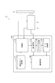
- the control system 1 is a system in which a drive target is made to perform a desired operation by a motor. There are no particular restrictions on the shape, structure, and size of the drive target, and the number and size of motors. In the following, a case where there is one motor and the driving target is one rigid body will be illustrated.
- the control system 1 includes a motor 2, a sensor 3, and a control device 100.
- the motor 2 drives the drive target 4.
- the motor 2 may be a rotary motor that rotationally drives the drive target 4, or may be a linear motor that displaces the drive target 4 along a straight line.
- the motor 2 may be a synchronous motor or an induction motor.
- the motor 2 may be a permanent magnet type synchronous motor such as an SPM (Surface Permanent Magnet) motor or an IPM (Interior Permanent Magnet) motor, or a synchronous motor having no permanent magnet such as a synchronous reluctance motor. There may be.
- the sensor 3 detects the response value of the motor 2 corresponding to the control command.
- the response value include the position or speed of the motor 2.
- the rotation angle of the output shaft of the motor 2 corresponds to the "position”
- the rotation speed of the output shaft of the motor 2 corresponds to the "speed”.
- Specific examples of the sensor 3 include a rotary encoder that outputs a pulse signal having a frequency proportional to the operating speed of the motor 2. According to the rotary encoder, both the position and the speed of the motor 2 can be acquired.
- the control device 100 controls the motor 2 so that the drive target 4 performs a desired operation. Further, the control device 100 estimates the external force acting on the drive target 4 by a sensorless method that does not use a force sensor. As illustrated later, the control device 100 may control the motor 2 based on the estimated external force, or may detect the contact between the drive target 4 and the peripheral object based on the estimated external force. The state of the surrounding object may be estimated based on the estimated external force.
- the external force acting on the motor 2 can be estimated based on the driving force command by the control device 100. For example, when the driving force generated by the motor 2 sufficiently follows the driving force command, it can be estimated that an external force substantially matching the driving force command is acting on the motor 2.
- the external force acting on the drive target 4 Since the external force acting on the drive target 4 is also transmitted to the motor 2, the external force acting on the motor 2 includes the external force acting on the drive target 4. However, the external force acting on the motor 2 includes at least the inertial force of the driving target 4 in addition to the external force acting on the driving target 4. Further, the external force acting on the motor 2 includes components that are difficult to model, such as Coulomb friction, viscous friction, and variations in the shape, size, and weight of the driving object 4. Therefore, it is difficult to estimate the external force acting on the drive target 4 with high accuracy only based on the external force acting on the motor 2. On the other hand, the control device 100 improves the estimation accuracy of the external force acting on the drive target 4 by the sensorless method.
- the control device 100 drives the motor 2, estimates the first external force acting on the motor 2 at least based on the driving force command for driving the motor 2, and changes in the estimated value of the first external force.
- the profile data representing the above is stored in the data storage unit, the first external force newly estimated when the motor 2 is driven based on a predetermined operation pattern, and the profile data stored in the data storage unit.
- the second external force acting on the driving target 4 is estimated, and is configured to execute.
- the control device 100 has an operation pattern storage unit 111, a control unit 112, a first estimation unit 113, a profile generation unit 114, and a data storage unit as functional configurations (hereinafter referred to as “functional blocks”). It includes 115 and a second estimation unit 116.
- the operation pattern storage unit 111 stores at least one operation pattern.
- the operation pattern is data representing the transition (time change) of the operation target value of the motor 2.
- an operation pattern includes at least one operation command.
- the operation command determines at least the target position of the drive target 4.
- the operation command may include the target speed of the drive target 4 instead of the target position of the drive target 4, or may include both the target position and the target speed of the drive target 4.
- the operation pattern may include a plurality of operation commands in a time series.
- the operation pattern storage unit 111 may store a plurality of operation patterns. Each of the plurality of operation patterns may be a unit program for constructing an operation program for causing the drive target 4 to perform a series of operations.
- the control unit 112 drives the motor 2. For example, the control unit 112 generates drive power for operating the drive target 4 based on the operation pattern stored in the operation pattern storage unit 111, and supplies the drive power to the motor 2. For example, the control unit 112 acquires information on the current position and current speed of the drive target 4 based on the detected value of the sensor 3, and generates drive power so as to make these follow the target position and target speed.
- control unit 112 performs proportional calculation, proportional / integral calculation, proportional / integral / differential calculation, or the like on the deviation between the target position and the current position (hereinafter referred to as “positional deviation”) to obtain the position deviation.
- positional deviation the deviation between the target position and the current position
- control unit 112 performs proportional calculation, proportional / integral calculation, proportional / integral / differential calculation, or the like on the deviation between the target speed and the current speed (hereinafter referred to as “speed deviation”) to reduce the speed deviation.
- speed deviation proportional calculation, proportional / integral calculation, proportional / integral / differential calculation, or the like on the deviation between the target speed and the current speed
- the control unit 112 calculates a current command for making the driving force of the motor 2 follow the driving force command, and generates driving power so as to supply the driving current corresponding to the current command to the motor 2.
- the first estimation unit 113 estimates the first external force acting on the motor 2 based on at least the driving force command in the control unit 112. For example, the first estimation unit 113 may output a force corresponding to the driving force command as the estimation result of the first external force.
- the drive current matches the current command
- the drive current and the drive force command correlate with each other. In such a case, being based on the detected value of the driving current and being based on the current command are substantially synonymous with being based on the driving force command.
- the first estimation unit 113 may be a disturbance observer that estimates the first external force based on at least the driving force command and the response value of the motor 2. For example, the first estimation unit 113 estimates the inertial force acting on the motor 2 from the drive target 4 based on the response value of the motor 2 (for example, the current speed and the current position) and the known rigid body model of the drive target 4. , The value obtained by subtracting the inertial force from the driving force command may be output as the estimation result of the first external force.
- the profile generation unit 114 generates profile data representing the transition of the estimated value estimated by the first estimation unit 113. For example, the profile generation unit 114 repeatedly acquires the estimated value of the first external force from the first estimation unit 113 during the period when the control unit 112 drives the motor 2 based on the operation pattern stored in the operation pattern storage unit 111, and the period. Generates profile data representing the time change of the estimated value of the first external force in. The profile data generated thereby represents the transition of the estimated value estimated by the first estimation unit 113 when the control unit 112 drives the motor 2 based on the operation pattern in the past.
- the profile generation unit 114 may generate profile data in a state where no external force is applied to the drive target 4.
- the profile data generated thereby represents the transition of the estimated value estimated by the first estimation unit 113 in a state where no external force is applied to the driving target 4.
- the profile generation unit 114 may generate profile data for each of the plurality of operation patterns. As a result, a plurality of profile data corresponding to each of the plurality of operation patterns are generated. Each of the plurality of profile data represents the transition of the estimated value estimated by the first estimation unit 113 when the control unit 112 has driven the motor 2 in the past based on the corresponding operation pattern.
- the data storage unit 115 stores the profile data generated by the profile generation unit 114.
- the data storage unit 115 may store the plurality of profile data described above.
- the data storage unit 115 may store the estimated value of the first external force and the operation pattern in association with each other.
- FIG. 2 is a table illustrating profile data.
- the profile data includes a plurality of records in a time series. Each record contains a drive time, a position, a speed, and an estimate of the first external force.
- the drive time is the elapsed time from the start of the operation of the motor 2 based on the operation pattern to the estimation of the first external force (the drive time of the motor 2 based on the operation pattern).
- the position is the position of the motor 2 at the time of estimating the first external force.
- the position here may be the target position or the position detected by the sensor 3.
- the speed is the speed of the motor 2 at the time of estimating the first external force.
- the speed here may be the target speed or the speed detected by the sensor 3.
- the data storage unit 115 replaces the discrete values as illustrated in FIG.
- a function or the like representing the relationship with the estimated value of may be stored as profile data.
- the operation pattern may be a unit program for constructing an operation program.
- the second estimation unit 116 is referred to as an estimated value newly estimated by the first estimation unit 113 (hereinafter, referred to as “new estimated value”) when the control unit 112 is driving the motor 2 based on the operation pattern. ) And the profile data stored in the data storage unit 115, the second external force acting on the driving target 4 is estimated. For example, the second estimation unit 116 extracts an estimated value corresponding to the new estimated value (hereinafter, referred to as “estimated value to be compared”) from the profile data, and sets the new estimated value and the estimated value to be compared. The second external force is estimated based on the difference. For example, the second estimation unit 116 outputs a value obtained by subtracting the estimated value to be compared from the new estimated value as the estimation result of the second external force.
- the second estimation unit 116 may extract an estimated value to be compared from the profile data based on the drive time according to the operation pattern (the elapsed time 9 from the start of operation of the motor 2 based on the operation pattern).
- the second estimation unit 116 extracts an estimated value corresponding to the driving time at the time when the first estimated unit 113 outputs a new estimated value from the profile data.
- the second estimation unit 116 may extract an estimated value corresponding to the newly estimated estimated value from the profile data based on the response value of the motor 2. For example, the second estimation unit 116 may extract an estimated value corresponding to the position of the motor 2 at the time when the first estimated unit 113 outputs a new estimated value from the profile data. The second estimation unit 116 may extract an estimated value corresponding to the speed of the motor 2 at the time when the first estimated unit 113 outputs a new estimated value from the profile data. The second estimation unit 116 may extract an estimated value corresponding to the position and speed of the motor 2 at the time when the first estimated unit 113 outputs a new estimated value from the profile data.
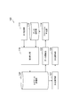
- the control device 100 may further include a data selection unit 121 as shown in FIG.
- the data selection unit 121 selects profile data corresponding to the operation pattern from a plurality of profile data of the data storage unit 115 when or before the control unit 112 starts driving the motor 2 based on the operation pattern.
- the second estimation unit 116 estimates the second external force based on the profile data selected by the data selection unit 121.
- control device 100 may further include a data update unit 122.
- the data update unit 122 updates the profile data stored in the data storage unit 115. Updating includes overwriting the existing profile data and writing new profile data while leaving the existing profile data as the old version.
- the data update unit 122 determines whether or not the profile data needs to be updated based on the profile data stored in the data storage unit 115 and the estimated value newly estimated by the first estimation unit 113, and needs to be updated. If it is determined, the profile data may be updated based on the estimated value newly estimated by the first estimation unit 113.
- the control device 100 further has a log data storage unit 129.
- the log data storage unit 129 stores log data representing the transition of the relationship between the estimated value newly estimated by the first estimation unit 113 and the profile data.
- the log data storage unit 129 stores the transition of the second external force estimated by the second estimation unit 116 as log data during the period in which the control unit 112 drives the motor 2 based on the operation pattern.
- the log data storage unit 129 may store the estimated value of the second external force in association with the operation pattern.
- the log data storage unit 129 may store a record in which the position and speed of the motor 2 and the estimated value of the second external force are associated with each other in time series.
- the position / speed may be a target position / speed, or may be a position / speed detected by the sensor 3.
- the data update unit 122 determines whether or not the profile data needs to be updated based on the log data stored in the log data storage unit 129. For example, the data update unit 122 determines whether or not the profile data needs to be updated based on whether or not the log data satisfies a predetermined determination criterion (hereinafter, referred to as “update determination criterion”).
- update determination criterion a predetermined determination criterion
- the profile data needs to be updated when the above-mentioned components that are difficult to model (Coulomb friction, viscous friction, variation in shape, size, weight, etc. of the driving object 4) change over time. Therefore, the update determination criteria are set in advance based on the characteristics that appear in the log data due to changes in the components that are difficult to model.
- the value of the estimated value of the second external force exceeds the predetermined threshold value over the entire range of the predetermined range in the log data, which is an example of the update determination criterion.
- the bearing is deteriorated or damaged, it is considered that a periodic change appears in the second external force in the log data.
- the magnitude of the specific frequency component exceeds a predetermined threshold value is also mentioned as an example of the update determination criterion.
- the fact that the second external force when the driving target 4 is in the posture exceeds the predetermined threshold value can also be a criterion for updating.
- the data update unit 122 causes the profile generation unit 114 to regenerate the profile data, and causes the profile data of the data storage unit 115 to be updated by the regenerated profile data.
- the data update unit 122 stores the uniform rise component in the profile data stored in the data storage unit 115. May be added over the entire area of.
- the control unit 112 may drive the motor 2 based on the operation pattern stored in the operation pattern storage unit 111 and the second external force estimated by the second estimation unit 116. For example, the control unit 112 calculates a correction value for following the external force based on the second external force estimated by the second estimation unit 116, and the action of the second external force determines the target position and target speed based on the operation pattern based on the correction value. Impedance control that corrects in the direction may be performed. The control unit 112 calculates the compensation value based on the model generated in advance by machine learning so as to represent the relationship between the second external force and the correction value, and the second external force newly estimated by the second estimation unit 116. You may.
- the control unit 112 may further execute feedforward control in which the feedforward compensation value is calculated based on the first external force estimated by the first estimation unit 113 and the feedforward compensation value is added to the driving force command.
- the first estimation unit 113 is an estimation condition for the first estimated value by estimating the first external force for calculating the feedforward compensation value and the first external force for estimating the second external force.
- the filter condition for the driving force command may be changed.
- the control device 100 may further include a contact detection unit 124.
- the contact detection unit 124 detects the contact between the driving target 4 and a peripheral object based on at least the second external force estimated by the second estimation unit 116.
- the contact detection unit 124 may detect contact between the driving target 4 and a peripheral object based on the increase in the second external force estimated by the second estimation unit 116.
- the control device 100 may be configured to further classify the drive result of the motor 2 based on the operation pattern into any of two or more types based on at least the estimated second external force.
- the control device 100 further includes a classification reference storage unit 125 and a classification unit 126.
- the classification standard storage unit 125 stores a standard for classifying the drive result of the motor 2 into one of two or more types. Specific examples of the two or more types include the quality of the operation result with respect to a predetermined standard, the quality of the work after the drive target 4 acts directly or indirectly, and after the drive target 4 acts directly or indirectly. The state of the work, etc.
- the classification unit 126 may classify the operation of the drive target 4 into "excellent” or "bad".
- the classification reference storage unit 125 has an upper limit profile representing an upper limit of the transition of the second external force when the operation of the drive target 4 is excellent, and a lower limit of the transition of the second external force when the operation of the drive target 4 is excellent. Memorize the lower limit profile that represents.
- the classification unit 126 classifies the operation of the drive target 4 as "excellent", and the estimated value of the second external force is the upper limit profile and the lower limit profile. When it is located outside the profile, the operation of the drive target 4 is classified as "defective".
- the classification unit 126 may classify the state of the work on which the drive target 4 acts directly or indirectly into “excellent” or “poor".
- the classification standard storage unit 125 stores an upper limit profile representing the upper limit of the transition of the second external force when the work is excellent and a lower limit profile representing the lower limit of the transition of the second external force when the work is excellent. ..
- the classification unit 126 classifies the state of the work as "excellent", and the estimated value of the second external force is the upper limit profile and the lower limit profile. If it is located outside the space, the state of the work is classified as "defective".
- the classification unit 126 may classify the state of the work on which the drive target 4 directly or indirectly acts into three or more subdivided categories. For example, the classification unit 126 may classify the dimensions of each part of the work into three or more categories.
- the classification standard storage unit 125 stores a table or a function representing the relationship between the second external force and the size of the work. The classification unit 126 calculates the dimensions of each part of the work based on the table or function and the estimated value of the second external force.
- the classification unit 126 classifies the drive result of the motor 2 based on the second external force estimated by the second estimation unit and the operation pattern based on the control unit 112 when the second external force is estimated. May be good.
- the classification standard storage unit 125 may store the classification standard for each operation pattern, and the classification unit 126 may select the classification standard corresponding to the operation pattern based on the control unit 112.
- the classification reference storage unit 125 may store a model generated in advance by machine learning so as to represent the relationship between the second external force and the drive result of the motor 2.
- the classification unit 126 classifies the driving result based on the transition of the estimated value of the second external force (for example, the transition stored by the log data storage unit 129) and the above model.
- the model may be generated so as to represent the relationship between the combination of the second external force and the operation pattern of the motor 2 when the second external force is generated, and the driving result of the motor 2.
- the classification reference storage unit 125 is generated so as to represent the relationship between the transition of the second external force, the operation pattern of the motor 2 when the transition of the second external force is generated, and the state of the work. Memorize the model that was created.
- the classification unit 126 classifies the work states into three or more types based on the transition of the estimated value of the second external force, the operation pattern based on the control unit 112 when the transition of the estimated value occurs, and the above model. Classify into.
- the second estimation unit 116 estimates the second external force based on the first external force acting on the motor 2. Therefore, the drive results of the motor 2 should be classified into two or more categories in consideration of the malfunction of at least one of the drive target 4 and the motor 2 and the change in the situation inside the control system 1 due to the slight fluctuation. Can be done. It is also possible to estimate the deterioration of the driving target 4 based on the estimation result of the second external force.
- the control device 100 may further include a deterioration estimation unit 127 and a deterioration notification unit 128.
- the deterioration estimation unit 127 estimates the deterioration of the drive target 4 based on at least the second external force estimated by the second estimation unit 116.
- the deterioration notification unit 128 notifies the deterioration of the drive target 4 estimated by the deterioration estimation unit 127 by transmitting notification data, displaying a notification to the display device, or the like.
- the estimation result of the second external force includes additional components due to changes over time in the above-mentioned components that are difficult to model (Coulomb friction, viscous friction, variation in shape, size, weight, etc. of the driving object 4).
- the deterioration estimation unit 127 estimates the deterioration of the drive target 4 based on the additional component.
- the above log data contains an additional component that uniformly rises over almost the entire range from the start of recording to the completion of recording.
- the deterioration estimation unit 127 is driven with an increase in Coulomb friction. Estimate the deterioration of subject 4.
- the deterioration estimation unit 127 estimates the deterioration of the drive target 4 accompanied by the increase in viscous friction.
- the deterioration estimation unit 127 estimates the deterioration of the bearing unit.
- the deterioration estimation unit 127 determines that the drive target is driven when the second external force when the drive target 4 is in the posture exceeds a predetermined threshold value.
- the deterioration of 4 may be estimated.
- the deterioration estimation unit 127 is divided into a model generated in advance by machine learning so as to represent the relationship between the transition of the second external force and the deterioration of the drive target 4, and the transition of the second external force estimated by the second estimation unit 116. Based on this, the deterioration of the drive target 4 may be estimated.
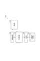
- FIG. 6 is a block diagram illustrating the hardware configuration of the control device 100.
- the control device 100 has a circuit 190.
- the circuit 190 includes one or more processors 191 and a memory 192, a storage 193, an input / output port 194, and a driver circuit 195.
- the storage 193 has a computer-readable storage medium, such as a non-volatile semiconductor memory.
- the storage 193 estimates the first external force acting on the motor 2 based on at least the driving force command for driving the motor 2 and the motor 2, and changes the estimated value of the first external force.
- the profile data to be represented is stored in the data storage unit, the first external force newly estimated when the motor 2 is driven based on a predetermined operation pattern, and the profile data stored in the data storage unit 115.
- the second external force acting on the drive target 4 is estimated based on the above, and the program for causing the control device 100 to execute is stored.
- the storage 193 stores a program for configuring each of the above-mentioned functional blocks in the control device 100.
- the memory 192 temporarily stores the program loaded from the storage medium of the storage 193 and the calculation result by the processor 191.
- the processor 191 constitutes each functional block of the control device 100 by executing the above program in cooperation with the memory 192.
- the input / output port 194 inputs / outputs an electric signal to / from the sensor 3 according to a command from the processor 191.
- the driver circuit 195 outputs drive power to the motor 2 in accordance with a command from the processor 191.
- control device 100 is not necessarily limited to one that configures each function by a program.
- the control device 100 may configure at least a part of its functions by a dedicated logic circuit or an ASIC (Application Specific Integrated Circuit) that integrates the logic circuit.
- ASIC Application Specific Integrated Circuit
- Control procedure Hereinafter, as an example of the control method, a control procedure executed by the control device 100 will be illustrated.
- This control procedure is to drive the motor 2, estimate the first external force acting on the motor 2 based at least based on the driving force command for driving the motor 2, and change the estimated value of the first external force.
- the profile data representing the above is stored in the data storage unit, the first external force newly estimated when the motor 2 is driven based on a predetermined operation pattern, and the profile data stored in the data storage unit.
- the second external force acting on the driving target 4 is estimated based on the above.
- This control procedure may further include generating profile data.
- a procedure for generating profile data and a procedure for driving the motor 2 based on the generated profile data will be illustrated.
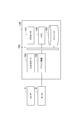
- FIG. 7 is a flowchart illustrating a procedure for generating profile data for each operation pattern when the operation pattern storage unit 111 stores a plurality of operation patterns.
- the control device 100 first executes steps S01, S02, S03, S04, S05, S06, and S07.
- step S01 the profile generation unit 114 selects any one of the plurality of operation patterns of the operation pattern storage unit 111.
- the selected motion pattern is referred to as a "target motion pattern”.
- step S02 the control unit 112 acquires information on the current position and the current speed of the drive target 4 based on the detected value of the sensor 3.
- step S03 the control unit 112 calculates a driving force command based on the target position and the target speed based on the target operation pattern and the current position and the current speed of the driving target 4.
- the control unit 112 performs proportional calculation, proportional / integral calculation, proportional / integral / differential calculation, or the like on the deviation between the target position and the current position (hereinafter referred to as “positional deviation”) to obtain the position deviation.
- positional deviation the control unit 112 performs proportional calculation, proportional / integral calculation, proportional / integral / differential calculation, or the like on the deviation between the target speed and the current speed (hereinafter referred to as “speed deviation”) to reduce the speed deviation.
- speed deviation proportional calculation, proportional / integral calculation, proportional / integral / differential calculation, or the like on the deviation between the target speed and the current speed
- step S04 the control unit 112 calculates a current command for making the driving force of the motor 2 follow the driving force command, and generates driving power so as to supply the driving current corresponding to the current command to the motor 2.
- step S05 the first estimation unit 113 estimates the first external force acting on the motor 2 based on at least the driving force command in the control unit 112.
- step S06 the profile generation unit 114 adds the record including the first external force estimated in step S05 to the profile data of the target operation pattern. For example, the profile generation unit 114 adds a record to the storage area of the profile data in the operation pattern storage unit 111.
- step S07 the profile generation unit 114 confirms whether the operation of the motor 2 according to the target operation pattern is completed.
- step S07 If it is determined in step S07 that the operation of the motor 2 according to the target operation pattern is not completed, the control device 100 returns the process to step S02. After that, the addition of the record to the profile data corresponding to the target operation pattern is repeated until the operation of the motor 2 according to the target operation pattern is completed. As a result, profile data representing the transition of the first external force is generated.
- step S07 When it is determined in step S07 that the operation of the motor 2 according to the target operation pattern is completed, the control device 100 executes step S08.
- step S08 the profile generation unit 114 confirms whether the generation of profile data has been completed for all the operation patterns stored in the operation pattern storage unit 111.
- step S09 the profile generation unit 114 changes the target operation pattern to another operation pattern for which profile data has not been generated. After that, the profile generation unit 114 returns the process to step S02. After that, the selection of the operation pattern and the generation of the profile data are repeated until the profile data is generated for all the operation patterns.
- step S08 When it is determined in step S08 that the generation of profile data has been completed for all the operation patterns, the control device 100 completes the generation of profile data.
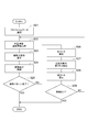
- FIG. 8 is a flowchart illustrating the driving procedure of the motor. More specifically, FIG. 8 shows a flowchart of an impedance control procedure for changing a target position / target speed based on an operation pattern based on the estimation result of the second external force.
- the control device 100 first executes steps S11, S12, S13, S14, and S15.
- step S11 the data selection unit 121 receives the profile data corresponding to the operation pattern based on the control unit 112 (the operation pattern selected by the motor 2 to drive the motor 2), and the data selection unit 121 selects a plurality of profile data of the data storage unit 115. Select from.
- the operation pattern based on the control unit 112 is referred to as a "driving operation pattern”
- the selected profile data is referred to as a "selecting profile”.
- step S12 the control unit 112 acquires information on the current position and current speed of the drive target 4 based on the detected value of the sensor 3.
- step S13 the control unit 112 calculates the driving force command based on the target position and the target speed based on the driving operation pattern and the current position and the current speed of the driving target 4, as in step S03.
- step S14 the control unit 112 generates driving power so that the driving force of the motor 2 follows the driving force command, as in step S04.
- step S15 the profile generation unit 114 confirms whether the operation of the motor 2 according to the driving operation pattern is completed.
- step S15 When it is determined in step S15 that the operation of the motor 2 according to the drive operation pattern is not completed, the control device 100 executes steps S16, S17, S18, and S19.
- step S16 the first estimation unit 113 newly estimates the first external force acting on the motor 2 based on at least the driving force command in the control unit 112.
- step S17 the second estimation unit 116 extracts the estimated value (the estimated value to be compared) corresponding to the estimated value (the new estimated value) newly estimated by the first estimation unit 113 from the selected profile. To do.
- step S18 the second estimation unit 116 estimates the second external force based on the difference between the new estimated value and the estimated value to be compared.
- step S19 the control unit 112 calculates a compensation value based on the estimated value of the second external force, and changes the next target position / speed based on the driving operation pattern to the action direction of the second external force. After that, the control device 100 returns the process to step S12. After that, until the driving operation pattern is completed, the driving of the motor 2 based on the driving operation pattern is continued while estimating the second external force and changing the target position and the target speed based on the estimation result.
- step S15 When it is determined in step S15 that the operation of the motor 2 based on the drive operation pattern is completed, the drive of the motor 2 based on the drive operation pattern is completed.
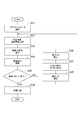
- FIG. 9 is a flowchart showing a modified example of the motor driving procedure. More specifically, FIG. 9 shows a control procedure for detecting contact between the driving target 4 and a peripheral object based on the estimation result of the second external force. Steps S21 to S28 from selection of the driving operation pattern to estimation of the second external force are the same as steps S11 to S18 described above. After estimating the second external force in step S28, the control device 100 executes step S29. In step S29, the contact detection unit 124 confirms whether or not the drive target 4 and the peripheral object are in contact with each other based on the estimated value of the second external force.
- step S29 When it is determined in step S29 that the drive target 4 and the peripheral object are not in contact with each other, the control device 100 returns the process to step S22. After that, the driving of the motor 2 based on the driving operation pattern is continued while monitoring the presence or absence of contact between the driving target 4 and the peripheral object.
- step S29 When it is determined in step S29 that the drive target 4 and the peripheral object are in contact with each other, the control device 100 forcibly completes a series of processes without returning to step S22. This completes the driving of the motor 2 based on the driving operation pattern.
- FIG. 10 is a flowchart showing another modified example of the driving procedure of the motor 2. More specifically, FIG. 10 shows a procedure for classifying the work states into two or more types based on the estimation result of the second external force after the driving of the motor 2 based on the operation pattern is completed. Steps S31 to S38 from the selection of the driving operation pattern to the estimation of the second external force are the same as the steps S11 to S18 described above. After estimating the second external force in step S38, the control device 100 returns the process to step S32. After that, the driving of the motor 2 based on the driving operation pattern is continued until the driving operation pattern is completed.
- step S39 the classification unit 126 classifies the state of the work on which the driving target 4 directly or indirectly acts into two or more types based on at least the estimation result of the second external force.
- the deterioration estimation unit 127 may estimate the deterioration of the drive target 4 based on at least the estimation result of the second external force. This completes the driving of the motor 2 based on the driving operation pattern.
- the above configuration is also applicable to a system in which there are a plurality of motors and the drive target includes a plurality of rigid bodies.
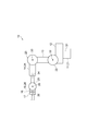
- the above configuration is also applicable to a robot system including the articulated robot illustrated in FIG.
- the robot 10 shown in FIG. 11 is a so-called 6-axis vertical articulated robot, and has a base 11, a swivel portion 12, arms 13, 14, 15, and a tool holding portion 16.
- the base 11 is fixed on the floor, the base, or an AGV (Automated Guided Vehicle) in the work area.
- the swivel portion 12 is provided on the base 11 so as to swivel around the vertical axis 31.
- the arm 13 is connected to the swivel portion 12 so as to swing around the axis 32 that intersects (for example, orthogonally) the axis 31.
- the intersection here includes a case where there is a twisting relationship such as a so-called grade separation.
- the arm 14 is connected to the tip of the arm 13 so as to swing around the axis 33 parallel to the axis 32.
- the arm 15 is connected to the tip of the arm 14 so as to swing around an axis 34 that intersects the axis 33 along the arm 14 and swings around an axis 35 that intersects (for example, is orthogonal to) the axis 34.
- the tool holding portion 16 is connected to the tip end portion of the arm 15 so as to rotate around the axis 36 along the center of the arm 15.
- the tool holding portion 16 holds various tools 17 such as a hand for gripping the work, a welding torch, a painting gun, and a screw tightening tool.
- the motor 21 swings the swivel portion 12 around the axis 31, the motor 22 swings the arm 13 around the axis 32, the motor 23 swings the arm 14 around the axis 33, and the motor 24 swings the arm 14 around the axis 33.
- the tip of the arm 14 is swiveled around 34, the motor 25 swings the arm 15 around the axis 35, and the motor 26 swivels the tool holding portion 16 around the axis 36.
- the tool holding unit 16 and the tool 17 are the driving targets of the motor 26.
- the arm 15, the tool holding portion 16, and the tool 17 are the driving targets of the motor 25.
- the tip of the arm 14, the arm 15, the tool holding portion 16 and the tool 17 are the driving targets of the motor 24.
- the arms 14, 15, the tool holding portion 16 and the tool 17 are the driving targets of the motor 23.
- the arms 13, 14, 15, the tool holding portion 16 and the tool 17 are the driving targets of the motor 22.
- the swivel portion 12, the arms 13, 14, 15, the tool holding portion 16 and the tool 17 are the driving targets of the motor 21.
- the shape and the moment of inertia of the drive target by the motor can change.
- the shape and moment of inertia of the object to be driven by the motor 21 change depending on the drive of the motors 22, 23, 24, 25, 26.
- the profile generation unit 114 provides profile data in which the transition of the estimated value of the first external force is associated with the operation pattern of the robot 10 as a whole for the motors 21, 22, 23, 24, 25, and 26, respectively. May be generated and stored in the data storage unit 115.
- Specific examples of the operation pattern of the robot 10 as a whole include data representing changes in the target position and the target posture of the tool holding unit 16.
- the first estimation unit 113 outputs a new estimated value to each of the motors 21, 22, 23, 24, 25, and 26 based on the driving force command.
- the second estimation unit 116 extracts the estimated value of the comparison target from each profile data, and estimates the second external force based on the difference between the new estimated value and the estimated value of the comparison target. Execute for each of 21, 22, 23, 24, 25, and 26.
- the control system 1 acts on the motor 2 based on at least the motor 2 that drives the drive target 4, the control unit 112 that drives the motor 2, and the driving force command in the control unit 112.
- the first estimation unit 113 for estimating an external force
- the data storage unit 115 for storing profile data representing the transition of the estimated value estimated by the first estimation unit 113
- the control unit 112 for the motor 2 based on a predetermined operation pattern.
- the second external force acting on the driving target 4 is estimated based on the estimated value newly estimated by the first estimation unit 113 and the profile data stored in the data storage unit 115 while driving.
- a second estimation unit 116 is provided.
- the first external force acting on the motor 2 contains components that are difficult to model, such as Coulomb friction, viscous friction, and variations in the shape, size, and weight of the drive target 4 by the motor 2. These components can be a factor that lowers the estimation accuracy of the external force (the second external force acting on the drive target 4) based on the force acting on the motor 2.
- the first external force newly estimated while the motor 2 is operating according to the operation pattern and the profile data representing the transition of the first external force estimated in the past are used. The external force is estimated based on this. If the newly estimated first external force contains a component that is difficult to model as described above, the previously estimated first external force also contains a similar component.
- the profile data may represent the transition of the estimated value estimated by the first estimation unit 113 when the control unit 112 drives the motor 2 based on the operation pattern in the past.
- the second external force can be estimated based on the new first external force estimated while driving the motor 2 in the operation pattern and the past first external force estimated while driving the motor 2 in the same operation pattern. Therefore, the estimation accuracy of the external force is further improved.
- the profile data may represent the transition of the estimated value estimated by the first estimation unit 113 in a state where no external force is acting on the driving target 4. In this case, the estimation accuracy of the external force is further improved by using the profile data in the state where the external force is not acting on the driving target 4 as a reference.
- the data storage unit 115 stores a plurality of profile data including the profile data, the plurality of profile data correspond to a plurality of operation patterns, and each of the plurality of profile data is in the past based on the corresponding operation patterns.
- the control unit 112 drives the motor
- the transition of the estimated value estimated by the first estimation unit 113 is represented, and the control unit 112 drives and controls the motor 2 based on any of a plurality of operation patterns.
- the system 1 further includes a data selection unit that selects profile data corresponding to the operation pattern based on the control unit 112 from a plurality of profile data
- the second estimation unit 116 is based on the profile data selected by the data selection unit 121.
- the second external force may be estimated. In this case, the estimation accuracy of the external force can be further improved by providing profile data for each operation pattern and using it properly according to the operation pattern.
- the first estimation unit 113 may be a disturbance observer that estimates the first external force based on at least the driving force command and the response value of the motor 2. In this case, the estimation accuracy of the external force is further improved. For example, according to the disturbance observer, of the effects of the operation of the drive target 4 on the motor 2, the portion that can be modeled (hereinafter referred to as “modeled effect”) is removed from the external force acting on the motor 2. The first external force can be estimated. According to the first external force estimated by removing the modeled influence, the newly estimated first external force is estimated even when the actual operation of the drive target 4 and the operation pattern deviate from each other. Since the modeled influence is removed in advance from both the value and the profile data, the above deviation is unlikely to affect the estimation accuracy of the second external force.
- the second estimation unit 116 extracts an estimated value corresponding to the newly estimated estimated value from the profile data, and based on the difference between the newly estimated estimated value and the extracted estimated value, the second external force May be estimated. In this case, the second external force can be easily estimated.
- the second estimation unit 116 extracts an estimated value corresponding to a newly estimated estimated value (hereinafter, may be referred to as an “estimated value to be compared”) from the profile based on the driving time according to the operation pattern. You may. In this case, the estimated value to be compared can be easily extracted based on the driving time according to the operation pattern.
- the second estimation unit 116 may extract an estimated value corresponding to the newly estimated estimated value from the profile data based on the response value of the motor 2.
- the estimated value corresponding to the newly estimated estimated value can be more appropriately extracted based on the response value of the motor 2.
- the second estimation unit 116 may extract the estimated value of the comparison target based on the current position of the motor 2, or may extract the estimated value of the comparison target based on the current speed of the motor 2. Estimates for comparison may be extracted based on both the current position and the current velocity of 2.
- the estimation accuracy of the external force can be further improved by extracting the estimated value at the position close to the current position.
- the estimation accuracy of the external force can be further improved by extracting the estimated value at a speed close to the current speed. Further, when extracting the estimated value to be compared based on both the current position and the current speed of the motor 2, the estimation accuracy of the external force is obtained by extracting the estimated value at the position close to the current position and the speed close to the current speed. Can be further improved.
- the control system 1 may further include a data update unit 122 that updates profile data. In this case, the estimation accuracy of the external force can be maintained.
- the data update unit 122 determines whether or not the update is necessary based on the profile data stored in the data storage unit 115 and the estimated value newly estimated by the first estimation unit 113, and determines that the update is necessary. In that case, the profile data may be updated based on the estimated value newly estimated by the first estimation unit 113. In this case, the profile data can be updated in a timely manner in response to changes in the situation such as aging deterioration and environmental changes. Therefore, the estimation accuracy of the external force is further improved.
- the control unit 112 may drive the motor 2 based on the operation pattern and the second external force estimated by the second estimation unit 116. In this case, torque control is possible without a torque sensor.
- the control system 1 further includes a classification unit 126 that classifies the driving result of the motor 2 by the control unit 112 based on the operation pattern into two or more categories based on at least the second external force estimated by the second estimation unit 116. You may. In this case, the improvement of the estimation accuracy of the external force contributes to the estimation of the appropriate state of the driving target 4 and the surrounding objects. Further, as described above, the second estimation unit 116 estimates the second external force based on the first external force acting on the motor 2. Therefore, the drive results of the motor 2 should be classified into two or more categories in consideration of the malfunction of at least one of the drive target 4 and the motor 2 and the change in the situation inside the control system 1 due to the slight fluctuation. Can be done.
- the classification unit 126 may classify the drive result based on the second external force estimated by the second estimation unit 116 and the operation pattern based on the control unit 112 when the second external force is estimated. .. In this case, since the classification based on the operation pattern and the second external force at that time is possible, more accurate classification is possible.
- the control system 1 may further include a deterioration estimation unit 127 that estimates the deterioration of the drive target 4 based on at least the second external force estimated by the second estimation unit 116.
- the estimation result of the external force can also be used for predicting the deterioration of the driving target 4.
- the control system 1 may further include a contact detection unit 124 that detects contact between the drive target 4 and a peripheral object based on at least the second external force estimated by the second estimation unit 116. In this case, the improvement of the estimation accuracy of the external force contributes to appropriate contact detection.
- Control system 1,21,22,23,24,25,26 ... Motor, 4 ... Drive target, 100 ... Control device, 112 ... Control unit, 113 ... First estimation unit, 115 ... Data storage unit, 116 ... second estimation unit, 121 ... data selection unit, 122 ... data update unit, 124 ... contact detection unit, 126 ... classification unit, 127 ... deterioration estimation unit.
Landscapes
- Engineering & Computer Science (AREA)
- General Physics & Mathematics (AREA)
- Automation & Control Theory (AREA)
- Physics & Mathematics (AREA)
- Power Engineering (AREA)
- Manufacturing & Machinery (AREA)
- Human Computer Interaction (AREA)
- Computer Hardware Design (AREA)
- Microelectronics & Electronic Packaging (AREA)
- Control Of Electric Motors In General (AREA)
- Testing And Monitoring For Control Systems (AREA)
- Feedback Control In General (AREA)
- Control Of Position Or Direction (AREA)
Priority Applications (4)
| Application Number | Priority Date | Filing Date | Title |
|---|---|---|---|
| JP2021532676A JP7222427B2 (ja) | 2019-07-18 | 2020-03-27 | 制御システム、制御装置及び制御方法 |
| CN202080051279.XA CN114127659B (zh) | 2019-07-18 | 2020-03-27 | 控制系统、控制方法以及非易失性存储器件 |
| EP20839682.0A EP4002053A4 (en) | 2019-07-18 | 2020-03-27 | CONTROL SYSTEM, CONTROL DEVICE AND CONTROL METHOD |
| US17/574,581 US11750133B2 (en) | 2019-07-18 | 2022-01-13 | External force estimation during motor control |
Applications Claiming Priority (4)
| Application Number | Priority Date | Filing Date | Title |
|---|---|---|---|
| JPPCT/JP2019/028261 | 2019-07-18 | ||
| PCT/JP2019/028261 WO2021009903A1 (ja) | 2019-07-18 | 2019-07-18 | ロボットシステム、ロボットの制御方法、サーボシステム |
| US201962940912P | 2019-11-27 | 2019-11-27 | |
| US62/940,912 | 2019-11-27 |
Related Child Applications (1)
| Application Number | Title | Priority Date | Filing Date |
|---|---|---|---|
| US17/574,581 Continuation US11750133B2 (en) | 2019-07-18 | 2022-01-13 | External force estimation during motor control |
Publications (1)
| Publication Number | Publication Date |
|---|---|
| WO2021009976A1 true WO2021009976A1 (ja) | 2021-01-21 |
Family
ID=74209787
Family Applications (1)
| Application Number | Title | Priority Date | Filing Date |
|---|---|---|---|
| PCT/JP2020/014290 Ceased WO2021009976A1 (ja) | 2019-07-18 | 2020-03-27 | 制御システム、制御装置及び制御方法 |
Country Status (5)
| Country | Link |
|---|---|
| US (1) | US11750133B2 (https=) |
| EP (1) | EP4002053A4 (https=) |
| JP (1) | JP7222427B2 (https=) |
| CN (1) | CN114127659B (https=) |
| WO (1) | WO2021009976A1 (https=) |
Families Citing this family (3)
| Publication number | Priority date | Publication date | Assignee | Title |
|---|---|---|---|---|
| JP2021049597A (ja) * | 2019-09-24 | 2021-04-01 | ソニー株式会社 | 情報処理装置、情報処理システム及び情報処理方法 |
| CN117916062A (zh) * | 2021-09-14 | 2024-04-19 | 发那科株式会社 | 机器人系统及机器人控制装置 |
| KR102642245B1 (ko) * | 2023-11-24 | 2024-02-29 | 주식회사 나우로보틱스 | 작업 공간 힘/가속도 외란 관측기 및 이를 포함하는 로봇 |
Citations (6)
| Publication number | Priority date | Publication date | Assignee | Title |
|---|---|---|---|---|
| JP2009297827A (ja) * | 2008-06-12 | 2009-12-24 | Fuji Electric Holdings Co Ltd | ロボット暴走判定方法およびロボット制御装置 |
| JP2012011403A (ja) | 2010-06-30 | 2012-01-19 | Yaskawa Electric Corp | ロボットシステム |
| JP2013066965A (ja) * | 2011-09-21 | 2013-04-18 | Toshiba Corp | ロボット制御装置、外乱判定方法およびアクチュエータ制御方法 |
| JP2013225284A (ja) * | 2012-04-20 | 2013-10-31 | Linestream Technologies | 動作システムのパラメータ推定法、そのパラメータ推定システム、動作プロファイルの生成方法およびその生成システム |
| JP2018065221A (ja) * | 2016-10-19 | 2018-04-26 | ファナック株式会社 | 機械学習により外力の検出精度を向上させた人協調ロボットシステム |
| JP2018089744A (ja) * | 2016-12-02 | 2018-06-14 | ファナック株式会社 | ロボットを制御するロボット制御装置、およびロボットに加わる外乱値を推定する方法 |
Family Cites Families (22)
| Publication number | Priority date | Publication date | Assignee | Title |
|---|---|---|---|---|
| US5103404A (en) * | 1985-12-06 | 1992-04-07 | Tensor Development, Inc. | Feedback for a manipulator |
| US4891764A (en) * | 1985-12-06 | 1990-01-02 | Tensor Development Inc. | Program controlled force measurement and control system |
| JPH074765B2 (ja) | 1986-03-03 | 1995-01-25 | 長尾 高明 | 曲面加工装置 |
| JPS6347058A (ja) | 1986-08-13 | 1988-02-27 | Daikin Ind Ltd | ロボツトの制御装置 |
| JP2676793B2 (ja) | 1988-06-30 | 1997-11-17 | トヨタ自動車株式会社 | 倣い制御ロボット |
| US4886529A (en) | 1988-07-08 | 1989-12-12 | Showa Precision Machinery Co., Ltd. | Polishing robot and polishing method using the same |
| JPH04135189A (ja) | 1990-09-21 | 1992-05-08 | Hitachi Ltd | ロボット制御装置 |
| KR100439466B1 (ko) | 1995-09-11 | 2004-09-18 | 가부시키가이샤 야스가와덴끼 | 로봇제어장치 |
| JP3383614B2 (ja) | 1999-08-04 | 2003-03-04 | 技術研究組合医療福祉機器研究所 | 水平多関節型ロボットアームのインピーダンス制御装置 |
| KR100486582B1 (ko) * | 2002-10-15 | 2005-05-03 | 엘지전자 주식회사 | 왕복동식 압축기의 스트로크 검출장치 및 방법 |
| US7456592B2 (en) * | 2003-12-17 | 2008-11-25 | Lg Electronics Inc. | Apparatus and method for controlling operation of reciprocating compressor |
| JP5262811B2 (ja) * | 2008-10-31 | 2013-08-14 | トヨタ自動車株式会社 | 車両のバネ上制振制御装置 |
| JP2011125986A (ja) | 2009-12-21 | 2011-06-30 | Saito-Seiki Co Ltd | 角ブロックの表面研削装置 |
| US8710777B2 (en) | 2012-04-20 | 2014-04-29 | Linestream Technologies | Method for automatically estimating inertia in a mechanical system |
| JP6136337B2 (ja) | 2013-02-15 | 2017-05-31 | 株式会社Ihi | 姿勢検知制御装置、研磨装置、および、姿勢検知制御方法 |
| CN105409110A (zh) * | 2013-08-19 | 2016-03-16 | 株式会社安川电机 | 电机驱动系统以及电机控制装置 |
| JP2016028842A (ja) | 2014-07-17 | 2016-03-03 | 株式会社ロボテック | アクチュエータシステム |
| JP6088583B2 (ja) | 2015-06-08 | 2017-03-01 | ファナック株式会社 | ロボットと力の表示機能を備えたロボット制御装置 |
| JP6457569B2 (ja) | 2017-02-24 | 2019-01-23 | ファナック株式会社 | サーボモータ制御装置、サーボモータ制御方法、及びサーボモータ制御用プログラム |
| CN107016208B (zh) * | 2017-04-17 | 2021-09-03 | 珞石(山东)智能科技有限公司 | 一种基于抖动控制的工业机器人外力估计方法 |
| CN107204726B (zh) * | 2017-07-20 | 2020-03-17 | 广东美芝制冷设备有限公司 | 永磁同步电机的控制方法及系统 |
| WO2019065427A1 (ja) | 2017-09-26 | 2019-04-04 | 倉敷紡績株式会社 | ロボットハンドシステム制御方法およびロボットハンドシステム |
-
2020
- 2020-03-27 JP JP2021532676A patent/JP7222427B2/ja active Active
- 2020-03-27 EP EP20839682.0A patent/EP4002053A4/en active Pending
- 2020-03-27 CN CN202080051279.XA patent/CN114127659B/zh active Active
- 2020-03-27 WO PCT/JP2020/014290 patent/WO2021009976A1/ja not_active Ceased
-
2022
- 2022-01-13 US US17/574,581 patent/US11750133B2/en active Active
Patent Citations (6)
| Publication number | Priority date | Publication date | Assignee | Title |
|---|---|---|---|---|
| JP2009297827A (ja) * | 2008-06-12 | 2009-12-24 | Fuji Electric Holdings Co Ltd | ロボット暴走判定方法およびロボット制御装置 |
| JP2012011403A (ja) | 2010-06-30 | 2012-01-19 | Yaskawa Electric Corp | ロボットシステム |
| JP2013066965A (ja) * | 2011-09-21 | 2013-04-18 | Toshiba Corp | ロボット制御装置、外乱判定方法およびアクチュエータ制御方法 |
| JP2013225284A (ja) * | 2012-04-20 | 2013-10-31 | Linestream Technologies | 動作システムのパラメータ推定法、そのパラメータ推定システム、動作プロファイルの生成方法およびその生成システム |
| JP2018065221A (ja) * | 2016-10-19 | 2018-04-26 | ファナック株式会社 | 機械学習により外力の検出精度を向上させた人協調ロボットシステム |
| JP2018089744A (ja) * | 2016-12-02 | 2018-06-14 | ファナック株式会社 | ロボットを制御するロボット制御装置、およびロボットに加わる外乱値を推定する方法 |
Non-Patent Citations (1)
| Title |
|---|
| See also references of EP4002053A4 |
Also Published As
| Publication number | Publication date |
|---|---|
| US11750133B2 (en) | 2023-09-05 |
| JP7222427B2 (ja) | 2023-02-15 |
| JPWO2021009976A1 (https=) | 2021-01-21 |
| CN114127659A (zh) | 2022-03-01 |
| EP4002053A1 (en) | 2022-05-25 |
| EP4002053A4 (en) | 2023-12-13 |
| CN114127659B (zh) | 2024-02-27 |
| US20230006590A1 (en) | 2023-01-05 |
Similar Documents
| Publication | Publication Date | Title |
|---|---|---|
| US11750133B2 (en) | External force estimation during motor control | |
| JP6400750B2 (ja) | 学習制御機能を備えた制御システム及び制御方法 | |
| US9073210B2 (en) | Information processing method, apparatus, and computer readable medium | |
| CN110340909B (zh) | 使用电动机编码器和传感器来进行学习控制的机器人系统 | |
| JP4813618B2 (ja) | イナーシャと摩擦を同時に推定する機能を有する電動機の制御装置 | |
| US10618164B2 (en) | Robot system having learning control function and learning control method | |
| US9701014B2 (en) | Robot control device for preventing misjudgment by collision judging part | |
| US8543239B2 (en) | Robot control apparatus | |
| JP5382359B2 (ja) | ロボットシステム | |
| US12337479B2 (en) | Robot system and robot control device | |
| CN112109080A (zh) | 调整辅助装置 | |
| JP2016013613A (ja) | ロボット制御方法、ロボット装置、プログラム、記録媒体及び組立部品の製造方法 | |
| JP5318727B2 (ja) | 情報処理方法及び装置並びにプログラム | |
| JP2017124455A (ja) | ロボット装置、ロボット制御方法、プログラム及び記録媒体 | |
| KR101485003B1 (ko) | 로봇의 위치 및 자세 제어 장치 및 방법 | |
| WO2016185589A1 (ja) | 故障診断装置及び故障診断方法 | |
| US11951625B2 (en) | Control method for robot and robot system | |
| US20230234223A1 (en) | Modeling of controlled object | |
| US20230286143A1 (en) | Robot control in working space | |
| TWI663031B (zh) | 適應性夾持的控制方法及電動夾爪 | |
| WO2020255312A1 (ja) | ロボットの動作調整装置、動作制御システムおよびロボットシステム | |
| JP5290934B2 (ja) | 情報処理方法及び装置並びにプログラム | |
| JP2018099736A (ja) | 故障診断装置及び故障診断方法 | |
| JP4632171B2 (ja) | モータ制御装置および制御方法 | |
| JP2022044396A (ja) | モータ制御装置 |
Legal Events
| Date | Code | Title | Description |
|---|---|---|---|
| 121 | Ep: the epo has been informed by wipo that ep was designated in this application |
Ref document number: 20839682 Country of ref document: EP Kind code of ref document: A1 |
|
| ENP | Entry into the national phase |
Ref document number: 2021532676 Country of ref document: JP Kind code of ref document: A |
|
| NENP | Non-entry into the national phase |
Ref country code: DE |
|
| ENP | Entry into the national phase |
Ref document number: 2020839682 Country of ref document: EP Effective date: 20220218 |