WO2021009849A1 - 粒子分別装置及びフローセルのアライメント方法 - Google Patents
粒子分別装置及びフローセルのアライメント方法 Download PDFInfo
- Publication number
- WO2021009849A1 WO2021009849A1 PCT/JP2019/027937 JP2019027937W WO2021009849A1 WO 2021009849 A1 WO2021009849 A1 WO 2021009849A1 JP 2019027937 W JP2019027937 W JP 2019027937W WO 2021009849 A1 WO2021009849 A1 WO 2021009849A1
- Authority
- WO
- WIPO (PCT)
- Prior art keywords
- flow cell
- flow
- speed
- light
- image
- Prior art date
- Legal status (The legal status is an assumption and is not a legal conclusion. Google has not performed a legal analysis and makes no representation as to the accuracy of the status listed.)
- Ceased
Links
Images




Classifications
-
- G—PHYSICS
- G01—MEASURING; TESTING
- G01N—INVESTIGATING OR ANALYSING MATERIALS BY DETERMINING THEIR CHEMICAL OR PHYSICAL PROPERTIES
- G01N15/00—Investigating characteristics of particles; Investigating permeability, pore-volume or surface-area of porous materials
- G01N15/10—Investigating individual particles
- G01N15/14—Optical investigation techniques, e.g. flow cytometry
- G01N15/1425—Optical investigation techniques, e.g. flow cytometry using an analyser being characterised by its control arrangement
-
- G—PHYSICS
- G01—MEASURING; TESTING
- G01N—INVESTIGATING OR ANALYSING MATERIALS BY DETERMINING THEIR CHEMICAL OR PHYSICAL PROPERTIES
- G01N15/00—Investigating characteristics of particles; Investigating permeability, pore-volume or surface-area of porous materials
- G01N15/10—Investigating individual particles
- G01N15/14—Optical investigation techniques, e.g. flow cytometry
-
- G—PHYSICS
- G01—MEASURING; TESTING
- G01N—INVESTIGATING OR ANALYSING MATERIALS BY DETERMINING THEIR CHEMICAL OR PHYSICAL PROPERTIES
- G01N15/00—Investigating characteristics of particles; Investigating permeability, pore-volume or surface-area of porous materials
- G01N15/10—Investigating individual particles
- G01N15/14—Optical investigation techniques, e.g. flow cytometry
- G01N15/1456—Optical investigation techniques, e.g. flow cytometry without spatial resolution of the texture or inner structure of the particle, e.g. processing of pulse signals
- G01N15/1459—Optical investigation techniques, e.g. flow cytometry without spatial resolution of the texture or inner structure of the particle, e.g. processing of pulse signals the analysis being performed on a sample stream
-
- G—PHYSICS
- G01—MEASURING; TESTING
- G01N—INVESTIGATING OR ANALYSING MATERIALS BY DETERMINING THEIR CHEMICAL OR PHYSICAL PROPERTIES
- G01N15/00—Investigating characteristics of particles; Investigating permeability, pore-volume or surface-area of porous materials
- G01N15/10—Investigating individual particles
- G01N15/14—Optical investigation techniques, e.g. flow cytometry
- G01N15/149—Optical investigation techniques, e.g. flow cytometry specially adapted for sorting particles, e.g. by their size or optical properties
- G01N15/1492—Optical investigation techniques, e.g. flow cytometry specially adapted for sorting particles, e.g. by their size or optical properties within droplets
-
- G—PHYSICS
- G01—MEASURING; TESTING
- G01N—INVESTIGATING OR ANALYSING MATERIALS BY DETERMINING THEIR CHEMICAL OR PHYSICAL PROPERTIES
- G01N15/00—Investigating characteristics of particles; Investigating permeability, pore-volume or surface-area of porous materials
- G01N15/10—Investigating individual particles
- G01N15/14—Optical investigation techniques, e.g. flow cytometry
- G01N15/149—Optical investigation techniques, e.g. flow cytometry specially adapted for sorting particles, e.g. by their size or optical properties
Definitions
- the present invention relates to a particle separation device and a flow cell alignment method.
- Patent Document 1 discloses a cell sorter.
- An object of the present invention is to provide a particle separation device and a flow cell alignment method capable of aligning a flow cell in a shorter time.
- the particle separation device of one aspect of the present invention includes a flow cell including a flow channel, an image sensor, a light intensity detector, a moving mechanism, and a control unit.
- the image sensor is configured to acquire an image relating to the flow axis of the flow channel.
- the light intensity detector is configured to detect the intensity of light emitted from a light radiator contained in a liquid flowing through a flow channel.
- the moving mechanism is configured to move the flow cell.
- the control unit is configured to control the moving mechanism.
- the control unit is configured to roughly adjust the position of the flow cell based on an image relating to the flow axis of the flow channel while continuously moving the flow cell at the first speed by controlling the movement mechanism.
- the control unit controls the movement mechanism to move the flow cell at a second speed slower than the first speed, and the first intensity of the first light emitted from the light radiator, which is detected by the light intensity detector, is determined. It is configured to make final adjustments to the position of the flow cell to maximize it.
- the flow cell alignment method of one aspect of the present invention includes a rough adjustment step and a final adjustment step.
- the coarse adjustment step the position of the flow cell is roughly adjusted based on the image of the flow axis of the flow channel of the flow cell while continuously moving the flow cell at the first velocity.
- the final adjustment step after the rough adjustment step, the first intensity of the first light emitted from the photoradiator contained in the liquid flowing through the flow channel is determined while moving the flow cell at a second speed slower than the first speed. Finalize the position of the flow cell to maximize it.
- the flow cell can be aligned in a shorter time.
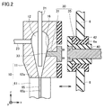
- FIG. 5 is a schematic partially enlarged cross-sectional view of the particle sorting apparatus according to the first to fourth embodiments. It is the schematic which shows the optical system included in the particle separation apparatus of Embodiment 1 and Embodiment 3.
- FIG. 5 is a schematic partial enlarged view of a sorting unit and a sample collecting unit included in the particle sorting apparatus of the first to fourth embodiments.
- It is a control block diagram of the particle separation apparatus of Embodiment 1 and Embodiment 3. It is a figure which shows the flowchart of the alignment method of the flow cell of Embodiment 1 and Embodiment 2.
- FIG. 2 It is the schematic sectional drawing of the particle separation apparatus of Embodiment 2 and Embodiment 4.
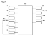
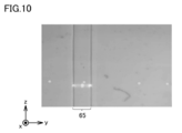
- FIG. It is the schematic which shows the optical system included in the particle separation apparatus of Embodiment 2 and Embodiment 4. It is a control block diagram of the particle separation apparatus of Embodiment 2 and Embodiment 4. It is a figure which shows the example of the image of the flow channel acquired by the image sensor of the particle separation apparatus of Embodiment 2 and Embodiment 4. It is a figure which shows the flowchart of the alignment method of the flow cell of Embodiment 3 and Embodiment 4.
- the particle separation device 1 includes a flow chamber 10, a vibration electrode 30, a vibration element 44, a charge supply unit 46, a moving mechanism 50, a detection optical system 83, a light intensity detector 99, a sort unit 110, and the like. It mainly includes a collecting unit 113, an image sensor 120, a control unit 130, a storage unit 140, a base 5, and a wall 6.
- the wall 6 is fixed to the base 5.
- the flow chamber 10, the sorting unit 110, and the collecting unit 113 are arranged on one side of the wall 6.
- the vibrating element 44, the moving mechanism 50, the detection optical system 83, the light intensity detector 99, the image sensor 120, and the control unit 130 are arranged on the opposite side of the wall 6.
- the flow chamber 10 includes a chamber 11 and a flow cell 60.
- a cavity 12 is provided inside the chamber 11.
- a first conduit 21 connected to the first tank 20 is inserted into the cavity 12 of the chamber 11.
- Particle 105 is, for example, a sample particle such as a biological particle (cell or chromosome) labeled with a fluorescent substance such as a fluorescent dye and a fluorescent antibody.
- the particles 105 are, for example, fluorescent beads (eg, SPHERO (TM) Rainbow Calibration Particles RCP-30-5).
- a second conduit 23 connected to the second tank 22 is inserted into the cavity 12 of the chamber 11.
- the second tank 22 stores the sheath liquid.
- the sheath liquid stored in the second tank 22 is supplied to the cavity 12 of the chamber 11 through the second conduit 23.
- the liquid containing the photoradiator stored in the first tank 20 is supplied to the cavity 12 of the chamber 11 through the first conduit 21.
- the photoradiator is, for example, a sample particle or a particle 105 such as a fluorescent bead.
- a liquid containing a photoradiator is supplied into the cavity 12 of the chamber 11 filled with the sheath liquid. In the cavity 12 of the chamber 11, the liquid containing the photoradiator is surrounded by the sheath liquid to form a sheath flow.
- the flow cell 60 is attached to the chamber 11.
- the flow cell 60 may be detachably coupled to the chamber 11.
- the flow cell 60 includes a flow cell main body 61.
- the flow cell main body 61 is made of a material transparent to laser light 71, fluorescence 77, side scattered light 77s and forward scattered light 77f (see FIG. 4) (for example, a transparent inorganic material such as quartz or a transparent resin material). Is formed of.
- the fluorescence 77 and the laterally scattered light 77s are emitted from a light emitter (eg, sample particles or particles 105 such as fluorescent beads) irradiated with the laser light 71.
- a light emitter eg, sample particles or particles 105 such as fluorescent beads
- a flow channel 65 is provided in the flow cell main body 61.
- the flow cell main body 61 is provided with a nozzle receiving portion 63 communicating with the flow channel 65.
- the flow channel 65 communicates with the cavity 12 of the chamber 11. Sheath flow flows from the cavity 12 to the flow channel 65 of the flow cell 60.
- the particles 105 contained in the sheath flow are aligned in a row along the flow axis (central axis) 65p of the flow channel 65.
- the flow axis 65p of the flow channel 65 extends in the first direction (z direction).
- the flow cell 60 includes a nozzle 68. A part of the nozzle 68 is housed in the nozzle receiving portion 63.
- the light source unit 70 irradiates the particles 105 arranged in a row on the flow channel 65 with the laser beam 71.
- the laser light 71 may include laser light having a plurality of wavelengths.
- the light source unit 70 includes lasers 70a and 70b. The wavelengths of the laser beams emitted by the lasers 70a and 70b are different from each other.
- the laser beam 71 emitted from the light source unit 70 irradiates the particles 105 flowing through the flow channel 65 via the optical combine unit 72.
- the laser beam 71 travels along a third direction (y direction) perpendicular to the first direction (z direction) and the second direction (x direction) and is incident on the flow channel 65.
- the optical combiner 72 includes, for example, a dichroic mirror. Fluorescence 77, forward scattered light 77f and side scattered light 77s are emitted from the particles 105.
- the laser beam 71 containing light of a plurality of wavelengths makes it possible to obtain a plurality of identification information of each particle 105 at one time. Particle 105 can be separated efficiently.
- the detection optical system 83 faces the flow cell 60 (the side surface of the flow cell main body 61) via the transparent window member 81.
- the transparent window member 81 is fitted in the opening 6b of the wall 6.
- the fluorescence 77 and the laterally scattered light 77s pass through the transparent window member 81 and enter the detection optical system 83.
- the detection optical system 83 guides the fluorescence 77 and the laterally scattered light 77s to the light intensity detector 99.
- the detection optical system 83 includes a detection side lens optical system 84, an optical fiber array 90, and a wavelength separation unit 92.
- the detection-side lens optical system 84 forms the fluorescence 77 and the laterally scattered light 77s on the incident surface of the optical fiber array 90 with low chromatic aberration and low image aberration.
- the optical fiber array 90 is arranged between the detection side lens optical system 84 and the wavelength separation unit 92.
- the optical fiber array 90 includes a plurality of optical fibers 91a and 91b.
- the plurality of optical fibers 91a and 91b are arranged so as to correspond to the plurality of lasers 70a and 70b, respectively.
- the optical fiber array 90 transmits the fluorescence 77 and the laterally scattered light 77s to the photointensity detector 99 (first photodetector 96a-96f, third photodetector 98).
- the wavelength separator 92 is arranged between the optical fiber array 90 and the photointensity detector 99 (specifically, the first photodetector 96a-96f, the third photodetector 98), and the fluorescence 77 and the side.
- the direction scattered light 77s is separated.
- the wavelength separation unit 92 includes dichroic mirrors 93a, 93b, 93c, 93d, 93e and wavelength filters 94a, 94b, 94c, 94d, 94e, 94f, 94g.
- the dichroic mirrors 93a-93e reflect and transmit light in different wavelength regions, respectively.
- the wavelength filters 94a-94f each transmit light in different wavelength regions and block light in other wavelength regions.
- the wavelength filter 94a-94f improves the detection accuracy of the fluorescence 77 in the first photodetector 96a-96f.
- the wavelength filter 94g transmits the laterally scattered light 77s and blocks the fluorescence 77.
- the wavelength filter 94g improves the detection accuracy of the laterally scattered light 77s in the third photodetector 98.
- the light intensity detector 99 is configured to detect the intensity of light emitted from a light radiator contained in a liquid flowing through a flow channel 65.
- the light intensity detector 99 includes a first photodetector 96a-96f, a second photodetector 97, and a third photodetector 98.
- the first photodetector 96a-96f is configured to measure the intensity of fluorescence 77 emitted from the photoradiator.
- the second photodetector 97 is configured to measure the intensity of the forward scattered light 77f emitted from the light emitter.
- the third photodetector 98 is configured to measure the intensity of the laterally scattered light 77s emitted from the light emitter.
- the first photodetector 96a-96f, the second photodetector 97 and the third photodetector 98 are, for example, photomultiplier tubes (PMTs) or photodiodes.
- Identification information of the particles 105 can be obtained by analyzing at least one of the intensity of the fluorescence 77, the intensity of the forward scattered light 77f, or the intensity of the side scattered light 77s detected by the light intensity detector 99 with the control unit 130. ..
- the wavelength filter 94h is arranged between the flow cell 60 (flow cell main body 61) and the second photodetector 97.
- the wavelength filter 94h transmits light in a wavelength region including the wavelength of forward scattered light 77f and blocks light in other wavelength regions.
- the wavelength filter 94h improves the detection accuracy of the forward scattered light 77f in the second photodetector 97.
- the vibration electrode 30 extends from the cavity 12 of the chamber 11 to the outside of the chamber 11.
- the vibrating electrode 30 passes through the opening 6a of the wall 6 and penetrates the wall 6.
- the vibrating electrode 30 includes a vibrating electrode portion 31 and a conductive portion 35.
- the plurality of convex portions of the vibrating electrode portion 31 are fitted into the plurality of concave portions of the conductive portion 35, and the vibrating electrode portion 31 is electrically and mechanically connected to the conductive portion 35.
- the vibrating electrode portion 31 can be positioned with respect to the conductive portion 35.
- the vibration electrode portion 31 is provided in the chamber 11.
- the vibration electrode portion 31 extends from the cavity 12 of the chamber 11 to the outside of the chamber 11.
- the end surface 33 of the vibration electrode portion 31 is exposed in the cavity 12 of the chamber 11.
- the end surface 33 of the vibration electrode portion 31 is smoothly connected to the surface 16 of the cavity 12 of the chamber 11. It is possible to prevent the sheath flow in the cavity 12 of the chamber 11 from being disturbed by the end surface 33 of the vibration electrode portion 31.
- the conductive portion 35 is inserted into the opening 6a of the wall 6 and is attached to the wall 6.
- the conductive portion 35 passes through the opening 6a and penetrates the wall 6.
- the conductive portion 35 is housed in the insulating sleeve 40.
- the insulating sleeve 40 is inserted into the hole of the sealing member 42.
- the sealing member 42 is inserted into the opening 6a.
- the sealing member 42 is an elastic seal such as a rubber seal.
- the sealing member 42 can be elastically deformed.
- the vibration electrode portion 31 is detachably connected to the conductive portion 35. Therefore, the flow chamber 10 is removable from the wall 6.
- the used flow chamber 10 can be easily replaced with a sterilized flow chamber 10 by applying radiation or heat.
- the vibrating element 44 is connected to the vibrating electrode 30. Specifically, the vibrating element 44 is coupled to the conductive portion 35.
- the vibrating element 44 has a ring shape, and the conductive portion 35 is fitted in the hole of the vibrating element 44.
- the ultrasonic vibration of the vibrating element 44 is transmitted to the sheath flow in the cavity 12 of the chamber 11 via the vibrating electrode 30.
- the vibrating element 44 is, for example, a piezo piezoelectric element. Jet flow 100 is ejected from the nozzle 68. The vibration generated by the vibrating element 44 is transmitted to the jet flow 100. Therefore, the droplet 104 is separated from the jet flow 100 at the breakoff point 101, which is the lower end of the jet flow 100. Each droplet 104 contains one particle 105.
- the charge supply unit 46 is connected to the conductive portion 35.
- the charge supply unit 46 supplies the electric charge according to the identification information of the particles 105 contained in the droplet 104 to the droplet 104 via the vibration electrode 30, the sheath flow and the jet flow 100. Specifically, the charge supply unit 46 changes the polarity and amount of the charge supplied to the droplet 104 according to the identification information of the particles 105 contained in the droplet 104.
- the sort unit 110 is a deflector that changes the falling direction of the droplet 104.
- the sort unit 110 is attached to the wall 6.
- the sort unit 110 includes a pair of deflection electrodes 111 and 112. By applying a voltage between the deflection electrodes 111 and 112, an electric field is formed between the deflection electrodes 111 and 112.
- the droplet 104 to which the electric charge is supplied from the charge supply unit 46 receives a force by the electric field between the deflection electrodes 111 and 112.
- the falling direction of the droplet 104 is changed according to the polarity and amount of the electric charge supplied to the droplet 104.
- the collecting unit 113 includes a plurality of sample collecting members 114 and a waste liquid collecting member 115.
- the collecting unit 113 further includes a holder 116 that holds a plurality of sample collecting members 114 and a waste liquid collecting member 115.
- the holder 116 is attached to the wall 6.
- the droplets 104 whose falling direction is changed in the sort unit 110 are collected by the corresponding sample collecting member 114, respectively. In this way, the particles 105 contained in the droplet 104 can be separated according to the identification information of the particles 105. Unwanted droplets 104 are collected by the waste liquid recovery member 115.
- the moving mechanism 50 is configured to move the flow cell 60.
- the moving mechanism 50 is, for example, a three-axis moving mechanism, and can move the flow channel 65 in the first direction (z direction), the second direction (x direction), and the third direction (y direction).
- the moving mechanism 50 is attached to the wall 6 via the fixing member 49.
- the moving mechanism 50 is connected to the vibrating electrode 30 (conductive portion 35) via the movable member 48.
- the vibrating electrode 30 (conductive portion 35) can move within a range in which the sealing member 42 can be deformed.
- the moving mechanism 50 moves the movable member 48 and the vibrating electrode 30 to move the flow chamber 10.
- the flow cell 60 attached to the flow chamber 10 can be moved by the moving mechanism 50.
- the image sensor 120 faces the transparent window member 121 fitted in the opening 6c of the wall 6.
- the image pickup device 120 is configured to acquire an image relating to the flow axis 65p of the flow channel 65.
- the image sensor 120 is not particularly limited, but is, for example, a CCD camera or a CMOS camera.
- the image of the flow axis 65p of the flow channel 65 is, for example, an image of a liquid (eg, jet flow 100) flowing out of the flow cell 60. Since the flow axis 65p of the flow channel 65 is coaxial with the flow axis of the liquid flowing out of the flow cell 60, the image of the liquid flowing out of the flow cell 60 is an example of the image relating to the flow axis 65p of the flow channel 65.
- the image of the liquid flowing out of the flow cell 60 may include an image of the breakoff point 101 of the liquid flowing out of the flow cell 60.
- the flow channel 65 and its flow axis 65p extend in the first direction (z direction).
- the control unit 130 includes a vibration element 44, a charge supply unit 46, a moving mechanism 50, and a photointensity detector 99 (first photodetector 96a-96f, second photodetector 97). , The third photodetector 98), the deflection electrodes 111 and 112, the image sensor 120, and the storage unit 140 are communicably connected.
- the storage unit 140 is, for example, a hard disk or a semiconductor memory.
- the control unit 130 is configured to transmit and read such information to and from the storage unit 140.
- the control unit 130 is, for example, a processor such as a CPU.
- the control unit 130 is configured to receive the intensity of fluorescence 77 measured by the first photodetector 96a-96f.
- the control unit 130 is configured to receive the intensity of the forward scattered light 77f measured by the second photodetector 97.
- the control unit 130 is configured to receive the intensity of the laterally scattered light 77s measured by the third photodetector 98.
- the control unit 130 analyzes at least one of the intensity of the fluorescence 77, the intensity of the forward scattered light 77f, or the intensity of the side scattered light 77s detected by the light intensity detector 99 to obtain the identification information of the particles 105. It is configured in.
- the control unit 130 is configured to control the vibrating element 44 to control the amplitude and frequency of ultrasonic vibration supplied from the vibrating element 44.
- the control unit 130 is configured to control the charge supply unit 46.
- the control unit 130 is configured to control the polarity and amount of the electric charge supplied from the electric charge supply unit 46 to the vibration electrode 30 according to the identification information of the particles 105.
- the control unit 130 is configured to control the electric field applied between the deflection electrodes 111 and 112.
- the control unit 130 is configured to receive an image regarding the flow axis 65p of the flow channel 65 acquired by the image sensor 120.
- the control unit 130 is configured to control the moving mechanism 50. Therefore, the control unit 130 can control the moving direction, moving distance, and moving speed of the flow cell 60 (flow chamber 10).
- the control unit 130 is configured to roughly adjust the position of the flow cell 60 based on the image of the flow axis 65p of the flow channel 65 while controlling the movement mechanism 50 to continuously move the flow cell 60 at the first speed.
- the image of the flow axis 65p of the flow channel 65 is, for example, an image of a liquid (eg, jet flow 100) flowing out of the flow cell 60.
- control unit 130 continuously moves the flow cell 60 at the first speed in the optical axis direction (second direction (x direction)) of the image sensor 120 in the flow cell 60.
- the control unit 130 roughly adjusts the position of the flow cell 60 in the second direction (x direction) so that the liquid flowing out of the flow cell 60 looks the finest.
- the liquid flowing out of the flow cell 60 is located at the focal position of the image sensor 120.
- the control unit 130 continuously moves the flow cell 60 in the third direction (y direction) at the first speed.
- the control unit 130 is positioned so that the liquid (jet flow 100) flowing out of the flow cell 60 is located at the first reference position in the third direction (y direction) in the image of the liquid flowing out of the flow cell 60 acquired by the image sensor 120.
- the position of the flow cell 60 in the third direction (y direction) is roughly adjusted.
- the first reference position may be the position in the third direction (y direction) of the liquid flowing out of the flow cell 60 in the image of the liquid flowing out of the flow cell 60 before the flow cell 60 is replaced.
- the first reference position may be the center of the third direction (y direction) in the image of the liquid flowing out of the flow cell 60 acquired by the image sensor 120.
- the control unit 130 controls the moving mechanism 50 to move the flow cell 60 at a second speed slower than the first speed, while the first light emitted from the light radiator detected by the light intensity detector 99. It is configured to finalize the position of the flow cell 60 so that the first strength is maximized.
- the light emitter is a fluorescent bead
- the first light includes forward scattered light 77f emitted from the fluorescent bead and fluorescence 77 emitted from the fluorescent bead.
- the first intensity of the first light emitted from the light radiator may be detected by using the light intensity detector 99 while continuously moving the flow cell 60 at a second speed slower than the first speed.
- the first intensity of the first light emitted from the light radiator may be detected by using the light intensity detector 99 while the flow cell 60 is stepped at a second speed slower than the first speed.
- Good That is, the flow cell 60 repeats moving by a minute distance and pausing.
- the light intensity detector 99 detects the first intensity of the first light emitted from the light radiator using the light intensity detector 99 while the flow cell 60 is temporarily stopped.
- the second velocity of the flow cell 60 is obtained by dividing the total movement distance of the flow cell 60 by the sum of the movement time of the flow cell 60 and the pause time of the flow cell 60.
- control unit 130 moves the flow cell 60 at the second speed in the optical axis direction (second direction (x direction)) of the image sensor 120 in the flow cell 60.
- the control unit 130 finalizes the position of the flow cell 60 in the second direction (x direction) so that the intensity of the forward scattered light 77f emitted from the light radiator detected by the second photodetector 97 is maximized. adjust.
- the control unit 130 moves the flow cell 60 in the third direction (y direction) at the second speed.
- the control unit 130 finalizes the position of the flow cell 60 in the third direction (y direction) so that the intensity of the fluorescence 77 emitted from the photoradiator detected by the first photodetector 96a-96f is maximized. adjust.
- the final adjustment of the position of the flow cell 60 is performed after the rough adjustment of the position of the flow cell 60. Therefore, the distance for moving the flow cell 60 at the second speed in the final adjustment of the position of the flow cell 60 is shorter than the distance for moving the flow cell 60 at the first speed in the rough adjustment of the position of the flow cell 60.
- the sheath liquid is supplied from the second tank 22 to the cavity 12 of the chamber 11.
- the sample liquid containing the particles 105 is supplied from the first tank 20 to the cavity 12 of the chamber 11 filled with the sheath liquid.
- the sample liquid is surrounded by the sheath liquid to form a sheath flow.
- the sheath flow flows into the flow cell 60.
- the particles 105 contained in the sample liquid are aligned in a row along the flow axis (central axis) 65p of the flow channel 65 of the flow cell 60.
- the laser beam 71 is irradiated from the light source unit 70 to each of the particles 105 arranged in a row in the flow channel 65. Fluorescence 77, forward scattered light 77f and side scattered light 77s are emitted from the particles 105.
- the light intensity detector 99 detects at least one of fluorescence 77, forward scattered light 77f, and side scattered light 77s.
- the control unit 130 analyzes at least one of the fluorescence 77, the forward scattered light 77f, and the side scattered light 77s to obtain the identification information of the particles 105.
- the sheath flow containing the particles 105 flows out from the flow cell 60 as a jet flow 100.
- the control unit 130 controls the vibrating element 44 to control the amplitude and frequency of the ultrasonic vibration supplied from the vibrating element 44. Ultrasonic vibration is applied to the jet flow 100 from the vibrating element 44 through the vibrating electrode 30.
- the jet flow 100 is separated into droplets 104 at the breakoff point 101. Each of the droplets 104 contains one particle 105.
- the control unit 130 controls the polarity and amount of the electric charge supplied from the electric charge supply unit 46 to the vibration electrode 30 according to the identification information of the particles 105.
- the sheath flow and the jet flow 100 are charged.
- the electric charge 104 corresponding to the identification information of the particles 105 contained in the droplet 104 is supplied to the droplet 104 separated from the jet flow 100 at the breakoff point 101.
- the charged droplet 104 is deflected by the sort unit 110.
- the droplet 104 is collected by a plurality of sample collecting members 114 or waste liquid collecting members 115. In this way, the particles 105 contained in the droplet 104 are separated.
- the alignment method of the flow cell 60 of the first embodiment will be described with reference to FIG.
- the method of aligning the flow cell 60 of the present embodiment is performed before the sample particles such as the biological particles labeled with the fluorescent substance are separated by the particle separation device 1.
- the method of aligning the flow cell 60 of the present embodiment is performed after replacing the flow cell 60 or the flow chamber 10.
- the alignment method of the flow cell 60 of the present embodiment includes a rough adjustment step (S10) and a final adjustment step (S20).
- the position of the flow cell 60 is roughly adjusted based on the image of the flow axis 65p of the flow channel 65 of the flow cell 60 while continuously moving the flow cell 60 at the first speed.
- the image of the flow axis 65p of the flow channel 65 is, for example, an image of a liquid (jet flow 100) flowing out of the flow cell 60.
- control unit 130 continuously moves the flow cell 60 at the first speed in the optical axis direction (second direction (x direction)) of the image sensor 120 in the flow cell 60.
- the control unit 130 makes the liquid flowing out of the flow cell 60 look the thinnest in the second direction (x direction) of the flow cell 60. Roughly adjust the position of.
- the control unit 130 continuously moves the flow cell 60 in the third direction (y direction) at the first speed.
- the control unit so that the liquid flowing out of the flow cell 60 (for example, the jet flow 100) is located at the first reference position in the third direction (y direction) in the image of the liquid flowing out of the flow cell 60 acquired by the image sensor 120.
- the 130 roughly adjusts the position of the flow cell 60 in the third direction (y direction).
- the first reference position may be the position in the third direction (y direction) of the liquid flowing out of the flow cell 60 in the image of the liquid flowing out of the flow cell 60 before the flow cell 60 is replaced.
- the first reference position may be the center of the third direction (y direction) in the image of the liquid flowing out of the flow cell 60 acquired by the image sensor 120.
- the first intensity of the first light emitted from the light radiator contained in the liquid flowing through the flow channel 65 is maximum.
- the position of the flow cell 60 is finally adjusted so as to be.
- the light emitter is a fluorescent bead
- the first light includes forward scattered light 77f emitted from the fluorescent bead and fluorescence 77 emitted from the fluorescent bead.
- control unit 130 moves the flow cell 60 at the second speed in the optical axis direction (second direction (x direction)) of the image sensor 120 in the flow cell 60.
- the control unit 130 finally adjusts the position of the flow cell 60 in the second direction (x direction) so that the intensity of the forward scattered light 77f emitted from the fluorescent beads, which is detected by the second photodetector 97, is maximized. To do.
- the control unit 130 moves the flow cell 60 in the third direction (y direction) at the second speed.
- the control unit 130 finally adjusts the position of the flow cell 60 in the third direction (y direction) so that the intensity of the fluorescence 77 emitted from the fluorescent beads, which is detected by the first photodetector 96a-96f, is maximized. To do.
- the final adjustment step (S20) is performed after the rough adjustment step (S10). Therefore, the distance for moving the flow cell 60 at the second speed in the final adjustment step (S20) is shorter than the distance for moving the flow cell 60 at the first speed in the rough adjustment step (S10).
- the alignment of the flow cell 60 in the first direction (z direction) is also based on the rough adjustment step (S10) based on the image regarding the flow axis 65p of the flow channel 65 of the flow cell 60 and the first intensity of the first light. It may be performed by the final adjustment step (S20).
- the light radiator is a bead or a bubble.
- the beads may be fluorescent beads or beads that do not contain a fluorescent substance.
- a liquid containing beads or bubbles containing no fluorescent substance may be stored in the first tank 20.
- the bubble has, for example, a diameter of 1 ⁇ m or more and 30 ⁇ m or less.
- the position of the flow cell 60 in the third direction (y direction) is aligned based on the laterally scattered light 77s emitted from the beads or bubbles.
- the control unit 130 moves the flow cell 60 in the third direction (y direction) at the second speed.
- the control unit 130 positions the flow cell 60 in the third direction (y direction) so that the intensity of the laterally scattered light 77s emitted from the beads or bubbles detected by the third photodetector 98 is maximized. Make final adjustments.
- the particle sorting device 1 of the present embodiment includes a flow cell 60 including a flow channel 65, an image sensor 120, a light intensity detector 99, a moving mechanism 50, and a control unit 130.
- the image pickup device 120 is configured to acquire an image relating to the flow axis 65p of the flow channel 65.
- the light intensity detector 99 is configured to detect the intensity of light emitted from a light radiator contained in a liquid flowing through a flow channel 65.
- the moving mechanism 50 is configured to move the flow cell 60.
- the control unit 130 is configured to control the moving mechanism 50.
- the control unit 130 is configured to roughly adjust the position of the flow cell 60 based on the image of the flow axis 65p of the flow channel 65 while controlling the movement mechanism 50 to continuously move the flow cell 60 at the first speed. There is.
- the control unit 130 controls the moving mechanism 50 to move the flow cell 60 at a second speed slower than the first speed, while the first light emitted from the light radiator detected by the light intensity detector 99. It is configured to finalize the position of the flow cell 60 so that the first strength is maximized.
- the flow cell 60 after the flow cell 60 is continuously moved at the first speed to roughly adjust the flow cell 60, the flow cell 60 can be moved at the second speed to finally adjust the position of the flow cell 60. Therefore, in the particle separation device 1 of the present embodiment, the flow cell 60 is adjusted at the second speed in order to finally adjust the position of the flow cell 60, as compared with the comparative example in which the flow cell 60 is aligned only in the final adjustment step without the rough adjustment step. The distance to move is reduced. The particle sorting device 1 can align the flow cell 60 in a shorter time.
- the alignment method of the flow cell 60 of the present embodiment includes a rough adjustment step (S10) and a final adjustment step (S20).
- the rough adjustment step (S10) the position of the flow cell 60 is roughly adjusted based on the image of the flow axis 65p of the flow channel 65 of the flow cell 60 while continuously moving the flow cell 60 at the first speed.
- the final adjustment step (S20) after the rough adjustment step (S10), the flow cell 60 is moved at a second speed slower than the first speed, and is emitted from a photoradiator contained in the liquid flowing through the flow channel 65. The position of the flow cell 60 is finally adjusted so that the first intensity of the first light is maximized.
- the flow cell 60 is continuously moved at the first speed to roughly adjust the flow cell 60, and then the flow cell 60 is moved at the second speed to finally adjust the position of the flow cell 60. There is. Therefore, in the alignment method of the flow cell 60 of the present embodiment, the flow cell 60 is finally adjusted in order to finally adjust the position of the flow cell 60, as compared with the method of the comparative example in which the flow cell 60 is aligned only in the final adjustment step without the rough adjustment step. The distance to move at the second speed is reduced.
- the flow cell 60 alignment method of the present embodiment can align the flow cell 60 in a shorter time.
- the photoradiator is a bead or a bubble that does not contain a fluorescent substance. Therefore, at the end of the alignment of the flow cell 60, the fluorescent substance is prevented from remaining in the chamber 11 and the flow cell 60.
- the light emitter which is a bead that does not contain bubbles or fluorescent material, keeps the flow cell 60 clean at the beginning of the fractionation of the sample particles, such as fluorescently labeled biological particles, and the sample particles are , Can be sorted with improved accuracy.
- the image regarding the flow axis 65p of the flow channel 65 is an image of the liquid (for example, jet flow 100) flowing out from the flow cell 60. Therefore, the flow cell 60 can be aligned in a shorter time.
- the particle sorting apparatus 1b of the second embodiment will be described with reference to FIGS. 2, 4 and 7 to 9.
- the particle sorting device 1b of the present embodiment has the same configuration as the particle sorting device 1 of the first embodiment, but is mainly different in the following points.
- the particle sorting device 1b includes an image pickup element 120b instead of the image pickup element 120 of the first embodiment.
- the particle sorting device 1b further includes a reflecting member 86 and a reflecting member driving mechanism 87.
- the image sensor 120b is configured to acquire an image relating to the flow axis 65p of the flow channel 65.
- the image sensor 120b is not particularly limited, but is, for example, a CCD camera or a CMOS camera.
- An image of the flow axis 65p of the flow channel 65 is, for example, an image of the flow channel 65 (see FIG. 10).
- the reflection member 86 is arranged between the detection side lens optical system 84 and the optical fiber array 90.
- the reflection member 86 reflects the image of the flow cell 60 toward the image pickup device 120b.
- the reflective member 86 is, for example, a half mirror.
- the reflection member drive mechanism 87 is configured to rotate or move the reflection member 86.
- control unit 130 is communicably connected to the image sensor 120b and the reflection member drive mechanism 87.
- the control unit 130 is configured to receive the image of the flow channel 65 acquired by the image sensor 120b.
- the image of the flow channel 65 is stored in the storage unit 140.
- the control unit 130 is configured to control the reflection member drive mechanism 87.
- the control unit 130 can control the reflection member drive mechanism 87 to position the reflection member 86 on the optical axis of the detection optical system 83.
- the reflection member 86 reflects the image of the flow channel 65 toward the image sensor 120b.
- the control unit 130 can control the reflection member drive mechanism 87 to retract the reflection member 86 from the optical axis of the detection optical system 83. Therefore, the reflecting member 86 prevents the intensity of the fluorescence 77 measured by the first photodetector 96a-96f and the intensity of the side scattered light 77s measured by the third photodetector 98 from being lowered.
- the control unit 130 is configured to roughly adjust the position of the flow cell 60 based on the image of the flow axis 65p of the flow channel 65 while controlling the movement mechanism 50 to continuously move the flow cell 60 at the first speed.
- the image relating to the flow axis 65p of the flow channel 65 is, for example, an image of the flow channel 65.
- control unit 130 continuously moves the flow cell 60 at the first speed in the optical axis direction (second direction (x direction)) of the image sensor 120b in the flow cell 60.
- the control unit 130 roughly adjusts the position of the flow cell 60 in the second direction (x direction) so that the side wall of the flow channel 65 looks the thinnest in the image of the flow channel 65 acquired by the image sensor 120b.
- the flow channel 65 is located at the focal position of the image sensor 120b.
- the control unit 130 continuously moves the flow cell 60 in the third direction (y direction) at the first speed.
- the control unit 130 determines that the side wall of the flow channel 65 is located at the first reference position (see FIG. 10) in the third direction (y direction) in the image of the flow channel 65 acquired by the image sensor 120b.
- the position of the flow cell 60 in the third direction (y direction) is roughly adjusted.
- the first reference position may be the position in the third direction (y direction) of the side wall of the flow channel 65 in the image of the flow channel 65 before the flow cell 60 is replaced.
- the first reference position may be the center of the third direction (y direction) in the image of the flow channel 65 acquired by the image sensor 120b.
- control unit 130 controls the moving mechanism 50 to move the flow cell 60 at a second speed slower than the first speed, and the light radiator is detected by the light intensity detector 99.
- the position of the flow cell 60 is finally adjusted so as to maximize the first intensity of the first light emitted from the flow cell 60.
- the light emitter is a fluorescent bead
- the first light includes forward scattered light 77f emitted from the fluorescent bead and fluorescence 77 emitted from the fluorescent bead.
- the particle separation method using the particle separation device 1b of the present embodiment is the same as the particle separation method using the particle separation device 1 of the first embodiment.
- the control unit 130 controls the reflection member driving mechanism 87 to retract the reflection member 86 from the optical axis of the detection optical system 83. Therefore, the reflecting member 86 prevents the intensity of the fluorescence 77 measured by the first photodetector 96a-96f and the intensity of the side scattered light 77s measured by the third photodetector 98 from being lowered.
- the alignment method of the flow cell 60 of the second embodiment will be described with reference to FIG.
- the alignment method of the flow cell 60 of the present embodiment includes the same steps as the alignment method of the flow cell 60 of the first embodiment, but is mainly different in the following points.
- the image sensor 120b is used to acquire an image relating to the flow axis 65p of the flow channel 65.
- the image relating to the flow axis 65p of the flow channel 65 is an image of the flow channel 65.
- the control unit 130 controls the reflection member drive mechanism 87 to position the reflection member 86 on the optical axis of the detection optical system 83.
- the reflection member 86 reflects the image of the flow channel 65 toward the image sensor 120b.
- control unit 130 continuously moves the flow cell 60 at the first speed in the optical axis direction (second direction (x direction)) of the image sensor 120b in the flow cell 60.
- the control unit 130 roughly adjusts the position of the flow cell 60 in the second direction (x direction) so that the side wall of the flow channel 65 looks the thinnest in the image of the flow channel 65 acquired by the image sensor 120b.
- the control unit 130 continuously moves the flow cell 60 in the third direction (y direction) at the first speed.
- the side wall of the flow channel 65 is located at the first reference position (see FIG. 10) from the first end side in the third direction (y direction) in the image of the flow channel 65 acquired by the image sensor 120b.
- the control unit 130 roughly adjusts the position of the flow cell 60 in the third direction (y direction).
- the first reference position may be the position in the third direction (y direction) of the side wall of the flow channel 65 in the image of the flow channel 65 before the flow cell 60 is replaced.
- the first reference position may be the center of the third direction (y direction) in the image of the flow channel 65 acquired by the image sensor 120b.
- the fine adjustment step (S20) of the present embodiment is the same as the fine adjustment step (S20) of the first embodiment.
- the control unit 130 controls the reflection member drive mechanism 87 to retract the reflection member 86 from the optical axis of the detection optical system 83. Therefore, the reflecting member 86 prevents the intensity of the fluorescence 77 measured by the first photodetector 96a-96f and the intensity of the side scattered light 77s measured by the third photodetector 98 from being lowered.
- the light radiator is a bead or a bubble, as in the modified example of the first embodiment.
- the first light includes forward scattered light 77f and side scattered light 77s emitted from beads or bubbles.
- the position of the flow cell 60 in the third direction (y direction) is aligned based on the laterally scattered light 77s emitted from the beads or bubbles.
- the alignment method of the particle separation device 1b and the flow cell 60 of the present embodiment has the same following effects as the effect of the alignment method of the particle separation device 1 and the flow cell 60 of the first embodiment.
- the image of the flow axis 65p of the flow channel 65 is the image of the flow channel 65. Therefore, the flow cell 60 can be aligned in a shorter time.
- the particle sorting device 1c of the third embodiment will be described with reference to FIGS. 1 to 5.
- the particle sorting device 1c of the present embodiment has the same configuration as the particle sorting device 1 of the first embodiment, but is mainly different in the following points.
- control unit 130 in addition to being configured in the same manner as in the first embodiment, is further configured as follows.
- the control unit 130 controls the moving mechanism 50 to continuously move the flow cell 60 at a third speed slower than the first speed and faster than the second speed, and the light radiator detected by the light intensity detector 99.
- the position of the flow cell 60 is finely adjusted so that the second intensity of the second light emitted from the flow cell 60 is maximized.
- the light emitter is a fluorescent bead
- the first light includes forward scattered light 77f emitted from the fluorescent bead and fluorescence 77 emitted from the fluorescent bead.
- Information on the third speed is further stored in the storage unit 140.
- control unit 130 continuously moves the flow cell 60 at the third speed in the optical axis direction (second direction (x direction)) of the image sensor 120 in the flow cell 60.
- the control unit 130 finely adjusts the position of the flow cell 60 in the second direction (x direction) so that the intensity of the forward scattered light 77f emitted from the fluorescent beads, which is detected by the second photodetector 97, is maximized. To do.
- the control unit 130 moves the flow cell 60 in the third direction (y direction) at the third speed.
- the control unit 130 finely adjusts the position of the flow cell 60 in the third direction (y direction) so that the intensity of the fluorescence 77 emitted from the fluorescent beads, which is detected by the first photodetector 96a-96f, is maximized. To do.
- the fine adjustment of the position of the flow cell 60 is performed after the rough adjustment of the position of the flow cell 60. Therefore, the distance for moving the flow cell 60 at the third speed in the fine adjustment of the position of the flow cell 60 is shorter than the distance for moving the flow cell 60 at the first speed in the rough adjustment of the position of the flow cell 60.
- the final adjustment of the position of the flow cell 60 is performed after the fine adjustment of the position of the flow cell 60. Therefore, the distance for moving the flow cell 60 at the second speed in the final adjustment of the position of the flow cell 60 is shorter than the distance for moving the flow cell 60 at the third speed in the fine adjustment of the position of the flow cell 60. The distance for moving the flow cell 60 at the second speed in the final adjustment of the present embodiment is shorter than the distance for moving the flow cell 60 at the second speed in the final adjustment of the first embodiment.
- the particle sorting method using the particle sorting device 1c of the present embodiment is the same as the particle sorting method using the particle sorting device 1 of the first embodiment.
- the alignment method of the flow cell 60 of the third embodiment will be described with reference to FIG.
- the alignment method of the flow cell 60 of the present embodiment includes the same steps as the alignment method of the flow cell 60 of the first embodiment, but between the rough adjustment step (S10) and the final adjustment step (S20), It is mainly different in that it further includes a fine adjustment step (S15).
- the second intensity of the second light emitted from the photoradiator is maximized while continuously moving the flow cell 60 at the third speed slower than the first speed and faster than the second speed.
- the position of the flow cell 60 is finely adjusted so as to be.
- the light emitter is a fluorescent bead
- the first light includes forward scattered light 77f emitted from the fluorescent bead and fluorescence 77 emitted from the fluorescent bead.
- control unit 130 continuously moves the flow cell 60 at the third speed in the optical axis direction (second direction (x direction)) of the image sensor 120 in the flow cell 60.
- the control unit 130 finely adjusts the position of the flow cell 60 in the second direction (x direction) so that the intensity of the forward scattered light 77f emitted from the fluorescent beads, which is detected by the second photodetector 97, is maximized. To do.
- the control unit 130 moves the flow cell 60 in the third direction (y direction) at the third speed.
- the control unit 130 finely adjusts the position of the flow cell 60 in the third direction (y direction) so that the intensity of the fluorescence 77 emitted from the fluorescent beads, which is detected by the first photodetector 96a-96f, is maximized. To do.
- the fine adjustment step (S15) is performed after the rough adjustment step (S10). Therefore, the distance for moving the flow cell 60 at the third speed in the fine adjustment step (S15) is shorter than the distance for moving the flow cell 60 at the first speed in the rough adjustment step (S10).
- the final adjustment step (S20) of the present embodiment is the same as the final adjustment step (S20) of the first embodiment, but is mainly different in the following points.
- the final adjustment step (S20) is performed after the fine adjustment step (S15).
- the distance for moving the flow cell 60 at the second speed in the final adjustment step (S20) is shorter than the distance for moving the flow cell 60 at the third speed in the fine adjustment step (S15).
- the distance for moving the flow cell 60 at the second speed in the final adjustment step (S20) of the present embodiment is further shorter than the distance for moving the flow cell 60 at the second speed in the final adjustment step (S20) of the first embodiment. ..
- the alignment of the flow cell 60 in the first direction (z direction) is also based on the rough adjustment step (S10) based on the image regarding the flow axis 65p of the flow channel 65 of the flow cell 60 and the second intensity of the second light. It may be carried out by a fine adjustment step (S15) and a final adjustment step (S20) based on the first intensity of the first light.
- the light radiator is a bead or a bubble, as in the modified example of the first embodiment.
- the first light and the second light include forward scattered light 77f and side scattered light 77s emitted from beads or bubbles, respectively.
- the position of the flow cell 60 in the third direction (y direction) is based on the laterally scattered light 77s emitted from the beads or bubbles. Aligned.
- the control unit 130 moves the flow cell 60 in the optical axis direction (second direction (x direction)) of the image sensor 120 in the flow cell 60 at a third speed. Move.
- the control unit 130 finely adjusts the position of the flow cell 60 in the second direction (x direction) so that the intensity of the forward scattered light 77f emitted from the beads or bubbles detected by the second photodetector 97 is maximized. adjust.
- the control unit 130 moves the flow cell 60 in the third direction (y direction) at the third speed.
- the control unit 130 positions the flow cell 60 in the third direction (y direction) so that the intensity of the laterally scattered light 77s emitted from the beads or bubbles detected by the third photodetector 98 is maximized. Make fine adjustments.
- the control unit 130 moves the flow cell 60 at the second speed in the optical axis direction (second direction (x direction)) of the image sensor 120 in the flow cell 60.
- the control unit 130 finalizes the position of the flow cell 60 in the second direction (x direction) so that the intensity of the forward scattered light 77f emitted from the beads or bubbles detected by the second photodetector 97 is maximized. adjust.
- the control unit 130 moves the flow cell 60 in the third direction (y direction) at the second speed.
- the control unit 130 positions the flow cell 60 in the third direction (y direction) so that the intensity of the laterally scattered light 77s emitted from the beads or bubbles detected by the third photodetector 98 is maximized. Make final adjustments.
- the alignment method of the particle separation device 1c and the flow cell 60 of the present embodiment has the same following effects as the effect of the alignment method of the particle separation device 1 and the flow cell 60 of the first embodiment.
- control unit 130 controls the moving mechanism 50 to continuously move the flow cell 60 at a third speed slower than the first speed and faster than the second speed, while increasing the light intensity. It is further configured to fine-tune the position of the flow cell 60 so that the second intensity of the second light emitted from the photoradiator detected by the detector 99 is maximized.
- the flow cell 60 is continuously moved at the first speed to roughly adjust the flow cell 60, and then the flow cell 60 is continuously moved at the third speed to fine-tune the flow cell 60, and then the flow cell 60 is moved to the second speed.
- the position of the flow cell 60 can be finally adjusted by moving at a speed. Therefore, the distance for moving the flow cell 60 at the second speed is further reduced in order to finally adjust the position of the flow cell 60.
- the particle sorting device 1c can align the flow cell 60 in a shorter time.
- the flow cell 60 is moved at a third speed slower than the first speed and faster than the second speed between the rough adjustment step (S10) and the final adjustment step (S20).
- a fine adjustment step (S15) is further provided in which the position of the flow cell 60 is finely adjusted so that the second intensity of the second light emitted from the light radiator is maximized while continuously moving.
- the flow cell 60 is continuously moved at the first speed to roughly adjust the flow cell 60, and then the flow cell 60 is continuously moved at the third speed to finely adjust the flow cell 60. , The flow cell 60 is moved at the second speed to finally adjust the position of the flow cell 60. Therefore, the distance for moving the flow cell 60 at the second speed is further reduced in order to finally adjust the position of the flow cell 60.
- the flow cell 60 alignment method of the present embodiment can align the flow cell 60 in a shorter time.
- the particle sorting apparatus 1d of the fourth embodiment will be described with reference to FIGS. 2, 4 and 7 to 9.
- the particle sorting device 1d of the present embodiment has the same configuration as the particle sorting device 1c of the third embodiment, but is mainly different in the following points.
- the particle sorting device 1d includes the image pickup device 120b of the second embodiment instead of the image pickup device 120 of the third embodiment.
- the image pickup device 120b is configured to acquire an image relating to the flow axis 65p of the flow channel 65.
- the image relating to the flow axis 65p of the flow channel 65 is, for example, an image of the flow channel 65.
- the particle sorting device 1d may further include a reflecting member 86 and a reflecting member driving mechanism 87, as in the second embodiment.
- the particle separation method using the particle separation device 1d of the present embodiment is the same as the particle separation method using the particle separation device 1c of the third embodiment.
- the control unit 130 controls the reflection member driving mechanism 87 to retract the reflection member 86 from the optical axis of the detection optical system 83. Therefore, the reflecting member 86 prevents the intensity of the fluorescence 77 measured by the first photodetector 96a-96f and the intensity of the side scattered light 77s measured by the third photodetector 98 from being lowered.
- the alignment method of the flow cell 60 of the fourth embodiment will be described with reference to FIG.
- the alignment method of the flow cell 60 of the present embodiment includes the same steps as the alignment method of the flow cell 60 of the third embodiment, but is mainly different in the following points.
- the image relating to the flow axis 65p of the flow channel 65 is similar to the rough adjustment step (S10) of the alignment method of the flow cell 60 of the second embodiment. , Image of flow channel 65.
- the fine adjustment step (S15) of the alignment method of the flow cell 60 of the present embodiment is the same as the fine adjustment step (S15) of the alignment method of the flow cell 60 of the third embodiment.
- the light radiator is a bead or a bubble, as in the modified example of the third embodiment.
- the first light and the second light include forward scattered light 77f and side scattered light 77s emitted from beads or bubbles, respectively.
- the position of the flow cell 60 in the third direction (y direction) is based on the laterally scattered light 77s emitted from the beads or bubbles. Aligned.
- the alignment method of the particle separation device 1d and the flow cell 60 of the present embodiment has the same following effects as the effect of the alignment method of the particle separation device 1c and the flow cell 60 of the third embodiment.
- the image of the flow axis 65p of the flow channel 65 is the image of the flow channel 65. Therefore, the flow cell 60 can be aligned in a shorter time.
- 1,1b, 1c, 1d particle separator 5 base, 6 wall, 6a, 6b, 6c opening, 10 flow chamber, 11 chamber, 12 cavity, 16 surface, 20 first tank, 21 first conduit, 22 2nd tank, 23 2nd conduit, 30 vibrating electrode, 31 vibrating electrode part, 33 end face, 35 conductive part, 40 insulating sleeve, 42 sealing member, 44 vibrating element, 46 charge supply part, 48 movable member, 49 fixing member , 50 movement mechanism, 60 flow cell, 61 flow cell main body, 63 nozzle receiving part, 65 flow channel, 65p flow axis, 68 nozzle, 70 light source part, 70a, 70b laser, 71 laser light, 72 optical combine part, 77 fluorescence, 77f forward scattered light, 77s side scattered light, 81,121 transparent window member, 83 detection optical system, 84 detection side lens optical system, 86 reflective member, 87 reflective member drive mechanism, 90 optical fiber array, 91a, 91b optical fiber , 92 wavelength separator, 93a-
Landscapes
- Chemical & Material Sciences (AREA)
- Dispersion Chemistry (AREA)
- Physics & Mathematics (AREA)
- Health & Medical Sciences (AREA)
- Life Sciences & Earth Sciences (AREA)
- Analytical Chemistry (AREA)
- Biochemistry (AREA)
- General Health & Medical Sciences (AREA)
- General Physics & Mathematics (AREA)
- Immunology (AREA)
- Pathology (AREA)
- Investigating, Analyzing Materials By Fluorescence Or Luminescence (AREA)
Priority Applications (3)
| Application Number | Priority Date | Filing Date | Title |
|---|---|---|---|
| PCT/JP2019/027937 WO2021009849A1 (ja) | 2019-07-16 | 2019-07-16 | 粒子分別装置及びフローセルのアライメント方法 |
| US17/595,718 US11965811B2 (en) | 2019-07-16 | 2019-07-16 | Particle sorting apparatus and method of aligning flow cell |
| JP2021532601A JP7373859B2 (ja) | 2019-07-16 | 2019-07-16 | 粒子分別装置及びフローセルのアライメント方法 |
Applications Claiming Priority (1)
| Application Number | Priority Date | Filing Date | Title |
|---|---|---|---|
| PCT/JP2019/027937 WO2021009849A1 (ja) | 2019-07-16 | 2019-07-16 | 粒子分別装置及びフローセルのアライメント方法 |
Publications (1)
| Publication Number | Publication Date |
|---|---|
| WO2021009849A1 true WO2021009849A1 (ja) | 2021-01-21 |
Family
ID=74210348
Family Applications (1)
| Application Number | Title | Priority Date | Filing Date |
|---|---|---|---|
| PCT/JP2019/027937 Ceased WO2021009849A1 (ja) | 2019-07-16 | 2019-07-16 | 粒子分別装置及びフローセルのアライメント方法 |
Country Status (3)
| Country | Link |
|---|---|
| US (1) | US11965811B2 (https=) |
| JP (1) | JP7373859B2 (https=) |
| WO (1) | WO2021009849A1 (https=) |
Families Citing this family (1)
| Publication number | Priority date | Publication date | Assignee | Title |
|---|---|---|---|---|
| US20230168178A1 (en) * | 2021-11-30 | 2023-06-01 | Cytek Biosciences, Inc. | Methods, apparatus, and systems for an optical fiber forward scatter channel in flow cytometers |
Citations (4)
| Publication number | Priority date | Publication date | Assignee | Title |
|---|---|---|---|---|
| JP2011252871A (ja) * | 2010-06-04 | 2011-12-15 | Hitachi High-Technologies Corp | 光学式検査装置、及び光学式検査装置のモデル予測によるスポット光の調整方法 |
| WO2013145836A1 (ja) * | 2012-03-30 | 2013-10-03 | ソニー株式会社 | マイクロチップ型光学測定装置及び該装置における光学位置調整方法 |
| JP2014063109A (ja) * | 2012-09-24 | 2014-04-10 | Canon Inc | 画像投射装置 |
| WO2014115409A1 (ja) * | 2013-01-28 | 2014-07-31 | ソニー株式会社 | 微小粒子分取装置、微小粒子分取方法及びプログラム |
Family Cites Families (6)
| Publication number | Priority date | Publication date | Assignee | Title |
|---|---|---|---|---|
| US4732479A (en) * | 1985-10-18 | 1988-03-22 | Canon Kabushiki Kaisha | Particle analyzing apparatus |
| JP5994337B2 (ja) * | 2012-03-30 | 2016-09-21 | ソニー株式会社 | 微小粒子分取装置及びディレイタイム決定方法 |
| US10036698B2 (en) * | 2015-06-19 | 2018-07-31 | Captl Llc | Time-sequential cytometry |
| WO2017068822A1 (ja) * | 2015-10-19 | 2017-04-27 | ソニー株式会社 | 画像処理装置、微小粒子分取装置及び画像処理方法 |
| JP6707257B2 (ja) | 2016-05-06 | 2020-06-10 | アライドフロー株式会社 | 処理装置 |
| US10466158B2 (en) * | 2017-04-11 | 2019-11-05 | Sony Corporation | Microparticle sorting apparatus and delay time determination method |
-
2019
- 2019-07-16 WO PCT/JP2019/027937 patent/WO2021009849A1/ja not_active Ceased
- 2019-07-16 US US17/595,718 patent/US11965811B2/en active Active
- 2019-07-16 JP JP2021532601A patent/JP7373859B2/ja active Active
Patent Citations (4)
| Publication number | Priority date | Publication date | Assignee | Title |
|---|---|---|---|---|
| JP2011252871A (ja) * | 2010-06-04 | 2011-12-15 | Hitachi High-Technologies Corp | 光学式検査装置、及び光学式検査装置のモデル予測によるスポット光の調整方法 |
| WO2013145836A1 (ja) * | 2012-03-30 | 2013-10-03 | ソニー株式会社 | マイクロチップ型光学測定装置及び該装置における光学位置調整方法 |
| JP2014063109A (ja) * | 2012-09-24 | 2014-04-10 | Canon Inc | 画像投射装置 |
| WO2014115409A1 (ja) * | 2013-01-28 | 2014-07-31 | ソニー株式会社 | 微小粒子分取装置、微小粒子分取方法及びプログラム |
Also Published As
| Publication number | Publication date |
|---|---|
| JP7373859B2 (ja) | 2023-11-06 |
| US20220260478A1 (en) | 2022-08-18 |
| US11965811B2 (en) | 2024-04-23 |
| JPWO2021009849A1 (https=) | 2021-01-21 |
Similar Documents
| Publication | Publication Date | Title |
|---|---|---|
| JP4304120B2 (ja) | 生物学的粒子をソーティングする装置及び方法 | |
| JP4990746B2 (ja) | 液体フローに含まれる生物学的粒子を分別する装置ならびにその方法 | |
| US7362424B2 (en) | Compositions and methods for drop boundary detection and radiation beam alignment | |
| JP5086101B2 (ja) | 細胞分類方法及び装置 | |
| EP2258169B1 (en) | Method for isolating X-chromosome bearing and Y-chromosome bearing populations of spermatozoa | |
| US8941081B2 (en) | Microparticle measurement apparatus and microparticle analysis method | |
| EP0210343A1 (en) | Flow cytometry apparatus with improved light beam adjustment | |
| US11492586B2 (en) | Particle sorting apparatus and particle sorting method | |
| US7158226B2 (en) | Optical system and method for exciting and measuring fluorescence on or in samples treated with fluorescent | |
| JP4304195B2 (ja) | 生物学的粒子をソーティングする装置及び方法 | |
| WO2020149042A1 (ja) | 微小粒子分取装置、微小粒子分取システム、液滴分取装置、及び液滴制御装置、並びに、液滴制御用プログラム | |
| KR20160126062A (ko) | 유동 세포계수기의 광학 시스템을 위한 시스템, 방법 및 장치 | |
| JP7683484B2 (ja) | 位置調整方法、微小粒子分析装置、及びプログラム | |
| JP7373859B2 (ja) | 粒子分別装置及びフローセルのアライメント方法 | |
| JP2020134414A (ja) | 試料測定装置および試料測定方法 | |
| JP7058448B2 (ja) | フローセル、フローチャンバ、粒子分別装置及び粒子分別装置用カートリッジ | |
| US12275027B2 (en) | Imaging apparatus for imaging a nozzle section of a droplet dispenser device, dispenser apparatus including the imaging apparatus, and applications thereof | |
| JP7780798B2 (ja) | マイクロチップ、微粒子分析装置及び計測装置 | |
| JP7779322B2 (ja) | 粒子分取装置、粒子分取装置用オリフィスユニット及び粒子分取方法 | |
| US20250389637A1 (en) | Droplet sorting system, droplet sorting method, and droplet sorting program | |
| WO2022264481A1 (ja) | 粒子分取装置、粒子分取方法及びプログラム | |
| CN117836606A (zh) | 粒子分选装置和粒子分选方法 |
Legal Events
| Date | Code | Title | Description |
|---|---|---|---|
| 121 | Ep: the epo has been informed by wipo that ep was designated in this application |
Ref document number: 19938014 Country of ref document: EP Kind code of ref document: A1 |
|
| ENP | Entry into the national phase |
Ref document number: 2021532601 Country of ref document: JP Kind code of ref document: A |
|
| NENP | Non-entry into the national phase |
Ref country code: DE |
|
| 122 | Ep: pct application non-entry in european phase |
Ref document number: 19938014 Country of ref document: EP Kind code of ref document: A1 |