WO2021006277A1 - 歯ブラシ - Google Patents
歯ブラシ Download PDFInfo
- Publication number
- WO2021006277A1 WO2021006277A1 PCT/JP2020/026593 JP2020026593W WO2021006277A1 WO 2021006277 A1 WO2021006277 A1 WO 2021006277A1 JP 2020026593 W JP2020026593 W JP 2020026593W WO 2021006277 A1 WO2021006277 A1 WO 2021006277A1
- Authority
- WO
- WIPO (PCT)
- Prior art keywords
- brush
- toothbrush
- engaging
- grip portion
- brush portion
- Prior art date
Links
Images


Classifications
-
- A—HUMAN NECESSITIES
- A46—BRUSHWARE
- A46B—BRUSHES
- A46B5/00—Brush bodies; Handles integral with brushware
Definitions
- the present invention relates to a toothbrush in which a brush portion divided into two and a grip portion are detachably connected and integrated.
- a toothbrush has a brush portion in which a hair bundle is planted and a grip portion extended in the brush portion. It is configured to include.
- the brush part and the grip part are integrated, so when replacing this with a new one, the whole including the grip part that can still be used sufficiently is included. It has been discarded. Therefore, it is wasteful and uneconomical, and is not desirable from the viewpoint of effective use of resources.
- Patent Document 1 proposes an assembly-type toothbrush in which a replacement brush (a brush assembly in which a hair bundle is planted) is detachably assembled to the head portion of the main body.
- Patent Document 2 proposes an assembly-type toothbrush in which a replacement brush is immersed in boiling water (temperature of about 80 ° C.) and attached / detached.
- the present invention has been made in view of the above problems, and an object of the present invention is to improve economic efficiency and improve resources without causing a decrease in toothbrushing effect or a feeling of discomfort during use by simply replacing only the brush portion.
- the purpose is to provide a toothbrush that can be effectively used.
- the present invention has a toothbrush (1) including a brush portion (2) in which a hair bundle (2a) is planted and a grip portion (3) extended in the brush portion (2). ),
- the brush portion (2) and the grip portion (3) are formed as separate bodies, and both are detachably connected and integrated.
- the grip part when replacing the toothbrush, only the brush part is replaced with a new one, and the grip part can be continuously used as it is, so that only the old brush part that has been used up needs to be discarded. For this reason, waste is eliminated, economic efficiency is improved, and resources are effectively used.
- the same handle can be used for a long period of time, it is possible to select and use one with high decorativeness and design or one using high-grade materials. Become. As a result, the toothbrush can be made into a high-value product that matches individual tastes as compared with the conventional disposable one.
- the size of the brush portion is the same as the size of the brush portion of the existing toothbrush, and there is no difference between the two, so that the tooth brushing effect is not deteriorated and a sense of discomfort during use is not caused.
- a male screw (2b) is formed in one (2) of the brush portion (2) and the grip portion (3), and a female screw hole (3a) is formed in the other (3). Then, by screwing the male screw (2b) into the female screw hole (3a), the brush portion (2) and the grip portion (3) may be detachably connected and integrated. ..
- the male screw formed on the brush portion is fitted into the female screw hole formed on the grip portion, and the brush portion is screwed to the grip portion by a simple operation of turning the brush portion. Can be done. Then, if the used brush portion is turned in the direction opposite to that at the time of mounting, the male screw and the female screw hole are released from the screw, and the brush portion can be easily removed from the grip portion and discarded. .. Therefore, even a child or an elderly person can easily attach / detach the brush portion to / from the grip portion.
- an engaging claw (12a) is formed on one (12) of the brush portion (12) and the grip portion (13), and an engaging groove (13b) is formed on the other (13).
- a new brush portion is attached to the grip portion and both are connected and integrated by a simple operation of engaging the engaging claw formed on the brush portion with the engaging groove formed on the grip portion. Can be transformed into. Then, if the engaged claw of the brush portion that has been used and the engaging groove of the grip portion are disengaged, the brush portion can be easily removed from the grip portion and discarded. Therefore, even a child or an elderly person can easily attach / detach the brush portion to / from the grip portion.
- a columnar convex portion (22A) is projected from one end (22) of the brush portion (22) and the grip portion (23) in the axial direction, and the shaft of the other (23).
- a circular hole (23A) into which the columnar convex portion (22A) is inserted and fitted is formed at one end in the direction, and an engaging protrusion (22a) along the circumferential direction is formed on a part of the outer periphery of the columnar convex portion (22A).
- the brush portion (22) and the grip portion (23) may be detachably connected and integrated.
- the columnar convex portion protruding from the brush portion is aligned with the circular hole of the grip portion, and the engaging protrusion formed on the outer circumference of the cylindrical convex portion is the inner circumference of the circular hole of the grip portion.
- an insertion plate (32a) and an engaging convex portion (32b) are formed on one (32) of the brush portion (32) and the grip portion (33), and the other (33).
- An insertion groove (33a) and an engagement recess (33b) are formed in the insertion groove (33a), the insertion plate (32a) is inserted into the insertion groove (33a), and the engagement convex portion (32b) is inserted into the engagement recess (32b).
- the insertion plate formed in the brush portion is inserted into the insertion groove formed in the grip portion, and the engaging convex portion formed in the brush portion is inserted into the engaging concave portion formed in the grip portion.
- a new brush portion can be attached to the grip portion and the two can be connected and integrated by a simple operation of engaging. Then, if the used brush portion is pulled out from the grip portion to release the engagement between the engaging convex portion of the brush portion and the engaging concave portion of the grip portion, the brush portion can be easily removed from the grip portion and discarded. can do. Therefore, even a child or an elderly person can easily attach / detach the brush portion to / from the grip portion.
- the toothbrush according to the present invention by simply replacing only the brush portion, it is possible to improve economic efficiency and effectively use resources without reducing the tooth brushing effect or causing discomfort during use. Is obtained.
- FIG. 8 It is a partial perspective view which shows the connection structure of the toothbrush which concerns on Embodiment 3 of this invention.
- 10A to 10C are sectional views taken along the line CC of FIG. 8 showing the connection process of the toothbrush according to the third embodiment of the present invention in that order.
- FIG. 1 is a side view of the toothbrush according to the first embodiment of the present invention
- FIG. 2 is a sectional view taken along line AA of FIG. 1
- FIG. 3 is an exploded side view of the toothbrush.
- the toothbrush 1 includes a brush portion 2 in which a hair bundle is planted, and a grip portion 3 which is a handle portion extending linearly from the brush portion 2.
- the grip portion 2 and the grip portion 3 are separately configured.
- the brush portion 2 and the grip portion 3 are detachably connected and integrated by a connecting structure described later. More precisely, the brush portion 2 is replaceable with a new one, and the brush portion 2 is detachably connected to the grip portion 3.
- the brush portion 2 is a portion for brushing teeth, and a hair bundle 2a having, for example, 20 to 24 tact (bundle or bundle) is planted in the main body (base portion) 2A of the brush portion 2. ..
- a hair bundle 2a hair made of a resin material such as nylon or polyester or a natural material is used. Further, a resin material such as polypropylene or polyester is used for the main body (base portion) 2A of the brush portion 2.
- the grip portion 3 which is the handle portion is a portion to be gripped by the user when brushing the teeth, and a resin material such as polypropylene or polyester is also used for this.
- the toothbrush needs to be replaced with a new one at an appropriate time (usually less than 2 months) because the hair bundle deteriorates due to use, but the toothbrush 1 according to the present embodiment is described above.
- the brush portion 2 and the grip portion 3 are separately configured, and both are detachably connected and integrated. Therefore, when replacing the toothbrush 1, only the brush portion 2 in which the hair bundle 2a has deteriorated can be replaced with a new one, and the grip portion 3 in which the hair bundle 2a has not deteriorated can be continuously used as it is.
- one end (the lower end of FIG. 3) in the axial direction (longitudinal direction) of the connecting side (the side connected to the grip portion 3) of the brush portion 2 A columnar male screw 2b that protrudes concentrically in the axial direction is integrally formed. Further, as shown in FIG. 3, a circular hole-shaped female screw hole 3a is formed at one end in the axial direction (upper end of FIG. 3) on the connecting side (the side connected to the brush portion 2) of the grip portion 3. There is.
- the outer diameter of the axial end portion of the brush portion 2 on the connecting side and the outer diameter of the axial end portion of the grip portion 3 on the connecting side are set to the same value (same diameter).
- the male screw 2b of the new brush portion 2 is aligned with the female screw hole 3a of the grip portion 3, and the brush portion 2 is used. Is turned around the center of the axis, the male screw 2b of the brush portion 2 is screwed into the female screw hole 3a of the grip portion 3, and the brush portion 2 is screwed into the grip portion 3 as shown in FIGS. 1 and 2. Both are connected and integrated.
- the toothbrush 1 shown in FIG. 1 in which the brush portion 2 and the grip portion 3 are connected and integrated in this way can be used for brushing teeth by the user gripping and operating the grip portion 3 in the same manner as a conventional toothbrush. Be done.
- the user can rotate the used brush portion 2 in the direction opposite to that at the time of attachment.
- the screw between the male screw 2b and the female screw hole 3a is released, and the brush portion 2 can be easily removed from the grip portion 3 and discarded.
- the toothbrush 1 when the toothbrush 1 reaches the replacement time, only the brush portion 2 is replaced with a new one, and the grip portion 3 can be continuously used as it is. Since it can be done, only the old brush part 2 that has been used up needs to be discarded. For this reason, waste is eliminated, economic efficiency is improved, and resources are effectively used. Further, since the same grip portion 3 can be used for a long period of time, it is possible to select and use one having high decorativeness and design, or one using a high-grade material. Become. As a result, the toothbrush 1 can be made into a high-value product that matches individual tastes as compared with the conventional disposable toothbrush.
- the size of the brush part 2 is the same as the size of the brush part of the existing toothbrush, and since there is no difference between the two, there is no deterioration in the tooth brushing effect and no discomfort during use. Further, since the grip portion 3 can be continuously and repeatedly used, the user selects a grip portion 3 having a color or design of his / her own preference and continues to use it for a long period of time. be able to.
- the brush portion 2 can be attached to and detached from the grip portion 3 by simply inserting the male screw 2b formed in the brush portion 2 into the female screw hole 3a formed in the grip portion 3 and turning the brush portion 2. Therefore, even a child or an elderly person can easily attach / detach the brush portion 2 to / from the grip portion 3.
- the male screw 2b is formed in the brush portion 2 and the female screw hole 3a is formed in the grip portion 3, but conversely, the female screw hole is formed in the brush portion 2 to grip. It goes without saying that the same effect as described above can be obtained even if the male screw is formed in the portion 3.
- Embodiment 2 of the present invention will be described below with reference to FIGS. 4 to 7.
- FIG. 4 is a side view of the toothbrush according to the second embodiment of the present invention
- FIG. 5 is a sectional view taken along line BB of FIG. 4
- FIG. 6 is a partial perspective view showing a connecting structure of the toothbrush
- FIGS. 7A to 7C are. It is a partial cross-sectional view which shows the connection process of the toothbrush in order.
- the basic configuration of the toothbrush 11 according to the present embodiment is the same as that of the toothbrush 1 according to the first embodiment, and the toothbrush 11 is independently configured as a separate brush portion 12 and grip portion 13. Since the brush portion 12 and the grip portion 13 are only different in the connection structure, the connection structure will be described below.
- rectangular plate-shaped brackets 12A are integrally projected at two opposing positions of the axial end (lower ends of FIGS. 5 and 6) on the connecting side of the brush portion 12.
- the engaging claws 12a are integrally projected inward (inward in the radial direction).
- the engaging claws 12a are allowed to pass through the two opposing positions on the outer periphery of the axial end portion (upper end portion in FIG. 6) on the connecting side of the grip portion 13. Rectangular axial grooves 13a are formed respectively. Then, an engaging groove 13b along the circumferential direction is formed on the small-diameter outer peripheral surface 13A of the portion where each axial groove 13a of the grip portion 13 is formed.
- the new brush portion 12 is moved toward the grip portion 13 in the direction of the arrow in FIG. 7A, and the two brackets thereof.
- the engaging claws 12a projecting from the inner surface of the 12A are aligned with the two axial grooves 13a formed in the grip portion 13.
- the two engaging claws 12a of the brush portion 12 form an axial groove 13a of the grip portion 13. It is elastically deformed so as to come into contact with the outer peripheral surface 13A of the portion and spread outward.
- the brush portion 12 is further pushed toward the grip portion 13, and as shown in FIG. 7C, when the engaging claws 12a of the brush portion 12 match the engaging grooves 13b of the grip portion 13, each bracket 12A In order to return to the original positions by the elastic restoring force, the engaging claws 12a projecting from each bracket 12A are engaged with the engaging grooves 13b of the gripping portion 13, and the brush portion 12 is connected to the gripping portion 13. Both are integrated.
- the user spreads the bracket 12A of the brush portion 12 with a tool or the like and projects it into the bracket 12A. If the engagement between the engaging claw 12a and the engaging groove 13b is released, the brush portion 12 can be easily removed from the grip portion 13 and discarded.
- the brush portion 12 is gripped by a simple operation of engaging and disengaging the engaging claw 12a on the brush portion 12 side with respect to the engaging groove 13b on the grip portion 13 side. Since it can be attached to and detached from 13, even a child or an elderly person can easily replace the old brush portion 12 with a new one.
- the engaging claw 12a is formed on the brush portion 12 side and the engaging groove 13b is formed on the grip portion 13 side, but on the contrary, the engaging groove is formed on the brush portion 12 side.
- the same effect as described above can be obtained even if the engaging claw is formed on the grip portion 13 side.
- Embodiment 3 of the present invention will be described below with reference to FIGS. 8 to 10.
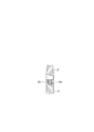
- FIG. 8 is a side view of the toothbrush according to the third embodiment of the present invention
- FIG. 9 is a partial perspective view showing a connecting structure of the toothbrush
- FIGS. 10A to 10C are C of FIG. 8 showing the connecting process of the toothbrush in that order.
- -C line sectional view.
- the basic configuration of the toothbrush 21 according to the present embodiment is the same as that of the toothbrush 1 according to the first embodiment, and the toothbrush 21 is independently configured as a separate brush portion 22 and grip portion 23. Since the brush portion 22 and the grip portion 23 differ only in the connecting structure, the connecting structure will be described below.
- a columnar convex portion 22A is integrally projected at one end (lower end in FIG. 9) of the brush portion 22 on the connecting side in the axial direction, and is gripped.
- a circular hole 23A into which the columnar convex portion 22A is inserted and fitted is formed at one end in the axial direction (upper end of FIG. 9) on the connecting side of the portion 23.
- engaging protrusions 22a along the circumferential direction are partially formed at two opposite positions on the outer periphery of the columnar convex portion 22A projecting from the brush portion 22, and the circular holes 23A formed in the grip portion 23.
- a rectangular axial groove 23a and an engaging groove 23b extending in the circumferential direction from the axial groove 23a are formed on the inner circumference of the above.
- the engaging projection 22a on the brush portion 22 side is axially oriented on the grip portion 23 side.
- the cylindrical convex portion 22A of the brush portion 22 is fitted into the circular hole 23A of the grip portion 23 in the state of being aligned with the groove 23a, and the brush portion 22 is pushed toward the grip portion 23 side (lower side of FIG. 10).
- the two engaging protrusions 22a on the brush portion 22 side passed through the two axial grooves 23a on the gripping portion 23 side, respectively, and these engaging protrusions 22a matched the engaging grooves 23b on the gripping portion 23 side.
- the brush portion 22 is turned around the center of the axis in a predetermined direction (clockwise in FIG. 10).
- the two engaging protrusions 22a on the brush portion 22 side engage with the two engaging grooves 23b on the grip portion 23 side, respectively.
- the brush portion 22 is rotated by a predetermined angle, as shown in FIG. 10C, the two engaging protrusions 22a are completely fitted into the two engaging grooves 23b, so that the new brush portion 22 is the grip portion 23.
- the toothbrush 21 shown in FIG. 8 is assembled by being attached to and integrated with each other.
- the user turns the brush portion 22 around the axis in the direction opposite to that at the time of assembly. Then, since the engagement between the two engaging protrusions 22a on the brush portion 22 side and the two engaging grooves 23b on the grip portion 23 side is released, the brush portion 22 is easily pulled out from the grip portion 23 and removed. The removed brush portion 22 can be discarded.
- the toothbrush 21 according to the present embodiment when the toothbrush 21 reaches the replacement time, only the brush portion 22 is replaced with a new one, and the grip portion 23 can be continuously used as it is. Therefore, the same effect as that of the toothbrushes 1 and 11 according to the first and second embodiments can be obtained.
- the cylindrical convex portion 22A of the brush portion 22 is fitted into the circular hole 23A of the grip portion 23, and the brush portion 22 is simply rotated by a predetermined angle around the axis center. Since the brush portion 22 can be attached to and detached from the grip portion 23 by operation, even a child or an elderly person can easily replace the old brush portion 22 with a new one.
- the engaging protrusion 22a is formed on the brush portion 22 side and the engaging groove 23b is formed on the grip portion 23 side, but on the contrary, the engaging groove is formed on the brush portion 22 side.
- the same effect as described above can be obtained even if the engaging protrusion is formed on the grip portion 23 side.
- Embodiment 4 of the present invention will be described below with reference to FIGS. 11 to 14.
- FIG. 11 is a partially broken front view of the toothbrush according to the fourth embodiment of the present invention
- FIG. 12 is a side view of the toothbrush
- FIG. 13 is an exploded front view of the toothbrush
- FIG. 14 is an exploded side view of the toothbrush. ..
- the basic configuration of the toothbrush 31 according to the present embodiment is the same as that of the toothbrushes 1, 11 and 21 according to the first to third embodiments, and the toothbrush 31 is an independently configured brush. Since the portion 32 and the grip portion 33 are connected and integrated, and the connecting structure between the brush portion 32 and the grip portion 33 is different, the connecting structure will be described below.
- a trapezoidal plate-shaped insertion plate 32a is integrally formed at one end (lower ends of FIGS. 13 and 14) on the connecting side of the brush portion 32 toward the lower part of the drawing. It is projected, and an elliptical engaging convex portion 32b in the front view is integrally projected from the insertion plate 32a.
- one end portion in the axial direction (upper end portion in FIG. 11) on the connecting side of the grip portion 33 has an insertion groove 33a having the same shape as the insertion plate 32a formed in the brush portion 32.
- An engaging recess 33b is formed in which the engaging convex portion 32b projecting from the insertion plate 32a engages.
- the insertion plate 32a of the new brush portion 32 is inserted into the insertion groove 33a of the grip portion 33. Then, as shown in FIG. 11, the engaging convex portion 32b projecting from the insertion plate 32a engages with the engaging concave portion 33b formed in the grip portion 33, so that the brush portion 32 is connected to the grip portion 33. And both are integrated.
- the user can pull the brush portion 32 in the direction of pulling it out from the grip portion 33, and the difference between the brush portions 32.
- the engagement between the engaging convex portion 32b integrally protruding from the insertion plate 32a and the engaging concave portion 33b formed in the grip portion 33 is released. Therefore, as shown in FIGS. 13 and 14, the brush portion 32 can be easily removed from the grip portion 33 and discarded.
- the toothbrush 31 according to the present embodiment when the toothbrush 31 reaches the replacement time, only the brush portion 32 is replaced with a new one, and the grip portion 33 can be continuously used as it is. Therefore, the same effect as that of the toothbrushes 1, 11 and 21 according to the first to third embodiments can be obtained.
- the brush portion 32 can be attached to and detached from the grip portion 13 by a simple operation of inserting or pulling out the brush portion 32 into the grip portion 33. Even an elderly person can easily replace the old brush portion 32 with a new one.
- the insertion plate 32a and the engaging convex portion 32b are formed on the brush portion 32 side, and the insertion groove 33a and the engaging concave portion 33b are formed on the grip portion 33 side, but the opposite is true.
- the same effect as described above can be obtained even if the insertion groove and the engaging concave portion are formed on the brush portion 32 side and the insertion plate and the engaging convex portion are formed on the grip portion 33 side.
- connecting structure of the brush portion and the grip portion in the toothbrush according to the present invention is not limited to those exemplified above, and it goes without saying that any other connecting structure can be adopted.
Landscapes
- Brushes (AREA)
Abstract
本発明の課題は、ブラシ部のみを簡単に交換することによって、歯磨き効果の低下や使用時の違和感を招くことなく、経済性の向上や資源の有効利用を図ることができる歯ブラシを提供することである。毛束2aが植設されたブラシ部2と、該ブラシ部2に延設された把持部3とを備える歯ブラシ1を、前記ブラシ部2と前記把持部3とをそれぞれ別体に構成し、両者を着脱可能に連結一体化して構成する。ブラシ部2と把持部3との連結構造として、例えば、前記ブラシ部2に雄ネジ2bを形成し、前記把持部3に雌ネジ穴3aを形成し、前記雄ネジ2bを前記雌ネジ穴3aに螺着することによって、前記ブラシ部2と前記把持部3とを着脱可能に連結一体化する構成を採用してもよい。
Description
本発明は、2分割されたブラシ部と把持部とを着脱可能に連結一体化して成る歯ブラシに関する。
虫歯や歯周病の予防には、歯ブラシによる歯間や歯茎のブラッシングが不可欠であるが、歯ブラシは、毛束が植設されたブラシ部と、該ブラシ部に延設された把持部とを含んで構成されている。
ところで、近年では電動歯ブラシも一部普及しているが、大部分(全体の90%以上)はブラシ部と把持部とが一体となった従来型のものが使用されている。この従来型の歯ブラシは、ブラシ部に植設された毛束の先端(毛先)が使用と共にバラバラに開いてくると、歯磨き効果が次第に低下してくるとともに、毛束に多数の菌が発生するため、適当な時期に新しいものと交換する必要がある。この歯ブラシの交換時期は、一般的には2箇月弱とされている。
電動歯ブラシ以外の従来型の歯ブラシは、ブラシ部と把持部とが一体化されているため、これを新しいものと交換する際には、まだ十分使用に耐えることができる把持部を含めて全体が廃棄されている。このため、無駄が多くて不経済であり、資源の有効利用の観点からも望ましいことではない。
そこで、例えば特許文献1には、替えブラシ(毛束が植設されたブラシ組立体)を本体のヘッド部分に着脱可能に組み付けて成る組立式歯ブラシが提案されている。
また、特許文献2には、替えブラシを熱湯(温度80℃程度)に漬けて着脱するようにした組立式歯ブラシが提案されている。
しかしながら、特許文献1において提案された組立式歯ブラシにおいては、替えブラシが組み込まれる本体のヘッド部が既存の歯ブラシのヘッド部よりも大きくなるため、奥歯が磨きにくく、奥歯の歯茎とその周辺に違和感を与えるという問題がある。
また、特許文献2において提案された組立式歯ブラシにおいても、替えブラシが着脱される本体のヘッド部が既存の歯ブラシのヘッド部よりも大きくなるため、特許文献1において提案された組立式歯ブラシと同様の問題が発生する他、替えブラシの着脱に熱湯を用いるために安全性に問題があるとともに、熱湯を用意する手間と時間を要し、替えブラシの着脱を子供や高齢者が簡単に行うことができないという問題がある。
本発明は、上記問題に鑑みてなされたもので、その目的は、ブラシ部のみを簡単に交換することによって、歯磨き効果の低下や使用時の違和感を招くことなく、経済性の向上や資源の有効利用を図ることができる歯ブラシを提供することにある。
上記目的を達成するため、本発明は、毛束(2a)が植設されたブラシ部(2)と、該ブラシ部(2)に延設された把持部(3)とを備える歯ブラシ(1)であって、前記ブラシ部(2)と前記把持部(3)とをそれぞれ別体に構成し、両者を着脱可能に連結一体化して成ることを特徴とする。
本発明によれば、歯ブラシの交換に際してはブラシ部のみを新しいものと交換し、把持部はそのまま継続して使用することができるため、使い終わった古いブラシ部のみを廃棄すれば済む。このため、無駄が省かれて経済性が高められるとともに、資源の有効利用が図られる。また、柄の部分は同じものを長期間に亘って使用することが可能となるため、装飾性やデザイン性の高いものや高級な材料を用いたものなどを選択して使用することが可能となる。これにより、従来の使い捨てのものと比較して、歯ブラシを個人の嗜好に合致した価値の高い商品とすることができる。
また、本発明によれば、ブラシ部の大きさは、既存の歯ブラシのブラシ部の大きさと同じで、両者に差はないため、歯磨き効果の低下や使用時の違和感を招くことがない。
また、上記歯ブラシ(1)において、前記ブラシ部(2)と前記把持部(3)の一方(2)に雄ネジ(2b)を形成し、他方(3)に雌ネジ穴(3a)を形成し、前記雄ネジ(2b)を前記雌ネジ穴(3a)に螺着することによって、前記ブラシ部(2)と前記把持部(3)とを着脱可能に連結一体化するようにしてもよい。
上記構成によれば、例えばブラシ部に形成された雄ネジを把持部に形成された雌ネジ穴に嵌め込んでブラシ部を回すだけの簡単な操作によって該ブラシ部を把持部にネジ結合することができる。そして、使い終わったブラシ部を取付時とは逆方向に回せば、雄ネジと雌ネジ穴との螺合が解除されて当該ブラシ部を把持部から簡単に取り外してこれを廃棄することができる。したがって、子供や高齢者であっても、ブラシ部を把持部に対して簡単に着脱することができる。
また、前記歯ブラシ(11)において、前記ブラシ部(12)と前記把持部(13)の一方(12)に係合爪(12a)を形成し、他方(13)に係合溝(13b)を形成し、前記係合爪(12a)を前記係合溝(13b)に係合させることによって、前記ブラシ部(12)と前記把持部(13)とを着脱可能に連結一体化するようにしてもよい。
上記構成によれば、例えばブラシ部に形成された係合爪を把持部に形成された係合溝に係合させるだけの簡単な操作によって、新しいブラシ部を把持部に取り付けて両者を連結一体化することができる。そして、使い終わったブラシ部の係合爪と把持部の係合溝との係合を解除すれば、ブラシ部を把持部から簡単に取り外してこれを廃棄することができる。したがって、子供や高齢者であっても、ブラシ部を把持部に対して簡単に着脱することができる。
また、前記歯ブラシ(21)において、前記ブラシ部(22)と前記把持部(23)の一方(22)の軸方向一端に円柱状凸部(22A)を突設し、他方(23)の軸方向一端に、前記円柱状凸部(22A)が挿入嵌合する円穴(23A)を形成するとともに、前記円柱状凸部(22A)の外周の一部に周方向に沿う係合突起(22a)を形成し、前記円穴(23A)の内周に、前記係合突起(22a)の通過を許容する軸方向溝(23a)と該軸方向溝(23a)から周方向に延びる係合溝(23b)を形成し、前記円柱状凸部(22A)を前記円穴(23A)に差し込んでこれを軸中心回りに所定角度だけ回して前記係合突起(22a)を前記係合溝(23b)に係合させることによって、前記ブラシ部(22)と前記把持部(23)とを着脱可能に連結一体化するようにしてもよい。
上記構成によれば、例えばブラシ部に突設された円柱状凸部を把持部の円穴に合わせ、該円柱状凸部の外周に形成された係合突起を把持部の円穴の内周に形成された軸方向溝を通過させながら円柱状凸部を円穴内に押し込んで嵌め込んだ後、ブラシ部を軸中心回りに所定角度だけ回すと、円柱状凸部に形成された係合突起が円穴の内周に形成された係合溝に係合するため、ブラシ部が把持部に連結されて一体化される。そして、使い終わったブラシ部を軸中心回りに取付時とは逆方向に所定角度だけ回せば、係合突起と係合溝との係合が解除されるため、ブラシ部を把持部から引き抜いてこれを廃棄することができる。したがって、子供や高齢者であっても、ブラシ部を把持部に対して簡単に着脱することができる。
また、前記歯ブラシ(31)において、前記ブラシ部(32)と前記把持部(33)の一方(32)に差込プレート(32a)と係合凸部(32b)を形成し、他方(33)に差込溝(33a)と係合凹部(33b)を形成し、前記差込プレート(32a)を前記差込溝(33a)に差し込み、前記係合凸部(32b)を前記係合凹部(33b)に係合させることによって、前記ブラシ部(32)と前記把持部(33)とを着脱可能に連結一体化するようにしてもよい。
上記構成によれば、例えばブラシ部に形成された差込プレートを把持部に形成された差込溝に差し込み、ブラシ部に形成された係合凸部を把持部に形成された係合凹部に係合させるだけの簡単な操作によって、新しいブラシ部を把持部に取り付けて両者を連結一体化することができる。そして、使い終わったブラシ部を把持部から引き抜いて該ブラシ部の係合凸部と把持部の係合凹部との係合を解除すれば、ブラシ部を把持部から簡単に取り外してこれを廃棄することができる。したがって、子供や高齢者であっても、ブラシ部を把持部に対して簡単に着脱することができる。
本発明に係る歯ブラシによれば、ブラシ部のみを簡単に交換することによって、歯磨き効果の低下や使用時の違和感を招くことなく、経済性の向上や資源の有効利用を図ることができるという効果が得られる。
以下に本発明の実施の形態を添付図面に基づいて説明する。
<実施の形態1>
図1は本発明の実施の形態1に係る歯ブラシの側面図、図2は図1のA-A線破断面図、図3は同歯ブラシの分解側面図である。
図1は本発明の実施の形態1に係る歯ブラシの側面図、図2は図1のA-A線破断面図、図3は同歯ブラシの分解側面図である。
本実施の形態に係る歯ブラシ1は、毛束が植設されたブラシ部2と、該ブラシ部2から直線状に延設された柄の部分である把持部3とを備えており、ブラシ部2と把持部3とはそれぞれ別体に構成されている。そして、ブラシ部2と把持部3とは、後述の連結構造によって着脱可能に連結一体化されている。より正確には、ブラシ部2は、新しいものと交換可能であって、このブラシ部2が把持部3に対して着脱可能に連結されている。
ここで、ブラシ部2は、歯をブラッシングするための部位であって、これの本体(ベース部)2Aには、例えば20~24タクト(房または束)の毛束2aが植設されている。ここで、毛束2aには、ナイロン、ポリエステルなどの樹脂素材または天然素材の用毛が用いられている。また、ブラシ部2の本体(ベース部)2Aには、ポリプロピレンやポリエステルなどの樹脂素材が用いられている。
また、柄の部分である把持部3は、歯のブラッシングの際にユーザーが把持する部分であって、これにもポリプロピレンやポリエステルなどの樹脂素材が用いられている。
ところで、一般的に歯ブラシは、使用によって毛束が劣化するために適当な時期(通常は2箇月未満)に新しいものと交換する必要があるが、本実施の形態に係る歯ブラシ1は、前述のようにブラシ部2と把持部3とがそれぞれ別体に構成されており、両者は、着脱可能に連結一体化されている。このため、歯ブラシ1の交換に際しては、毛束2aが劣化したブラシ部2のみを新しいものと交換し、劣化していない把持部3は、そのまま継続して使用することができる。
ここで、本実施の形態に係る歯ブラシ1におけるブラシ部2と把持部3との連結構造について説明する。
本実施の形態に係る歯ブラシ1においては、ブラシ部2の連結側(把持部3に連結される側)の軸方向(長手方向)一端(図3の下端)には、図3に示すように、軸方向に同心状に突出する円柱状の雄ネジ2bが一体に形成されている。また、把持部3の連結側(ブラシ部2に連結される側)の軸方向一端(図3の上端)には、図3に示すように、円穴状の雌ネジ穴3aが形成されている。なお、ブラシ部2の連結側の軸方向一端部の外径と把持部3の連結側の軸方向一端の外径は、同じ値(同径)に設定されている。
以上のような連結構造を有する歯ブラシ1において、ブラシ部2のみを新しいものと交換する場合には、新しいブラシ部2の雄ネジ2bを把持部3の雌ネジ穴3aに合わせて該ブラシ部2を軸中心回りに回せば、このブラシ部2の雄ネジ2bが把持部3の雌ネジ穴3aにねじ込まれ、図1及び図2に示すように、ブラシ部2が把持部3に螺着されて両者が連結一体化される。このようにブラシ部2と把持部3が連結一体化された図1に示す歯ブラシ1は、従来の歯ブラシと同様に、ユーザーが把持部3を把持して操作することによって歯のブラッシングに供せられる。
そして、使用によって歯ブラシ1のブラシ部2の毛束2aの劣化が進んだために当該歯ブラシ1が交換時期に達すると、ユーザーは、使い終わったブラシ部2を取付時とは逆方向に回せば、雄ネジ2bと雌ネジ穴3aとの螺合が解除されて当該ブラシ部2を把持部3から簡単に取り外してこれを廃棄することができる。
以上のように、本実施の形態に係る歯ブラシ1によれば、該歯ブラシ1が交換時期に達すると、ブラシ部2のみを新しいものと交換し、把持部3はそのまま継続して使用することができるため、使い終わった古いブラシ部2のみを廃棄すれば済む。このため、無駄が省かれて経済性が高められるとともに、資源の有効利用が図られる。また、把持部3は同じものを長期間に亘って使用することが可能となるため、装飾性やデザイン性の高いものや高級な材料を用いたものなどを選択して使用することが可能となる。これにより、従来の使い捨ての歯ブラシと比較して、歯ブラシ1を個人の嗜好に合致した価値の高い商品とすることができる。
また、ブラシ部2の大きさは、既存の歯ブラシのブラシ部の大きさと同じで、両者に差はないため、歯磨き効果の低下や使用時の違和感を招くことがない。また、把持部3を継続して繰り返し使用することができるため、ユーザーは、この把持部3として、自分の好みの色やデザインを施したものなどを選定してこれを長期に亘って使い続けることができる。
また、ブラシ部2の把持部3に対する着脱は、ブラシ部2に形成された雄ネジ2bを把持部3に形成された雌ネジ穴3aに嵌め込んでブラシ部2を回すだけの簡単な操作によってなされるため、子供や高齢者であっても、ブラシ部2を把持部3に対して簡単に着脱することができる。
なお、本実施の形態においては、ブラシ部2に雄ネジ2bを形成し、把持部3に雌ネジ穴3aを形成したが、これとは逆にブラシ部2に雌ネジ穴を形成し、把持部3に雄ネジを形成しても前記と同様の効果が得られることは勿論である。
<実施の形態2>
次に、本発明の実施の形態2を図4~図7に基づいて以下に説明する。
次に、本発明の実施の形態2を図4~図7に基づいて以下に説明する。
図4は本発明の実施の形態2に係る歯ブラシの側面図、図5は図4のB-B線断面図、図6は同歯ブラシの連結構造を示す部分斜視図、図7A~図7Cは同歯ブラシの連結過程をその順に示す部分断面図である。
本実施の形態に係る歯ブラシ11の基本構成は、前記実施の形態1に係る歯ブラシ1のそれと同じであり、該歯ブラシ11は、それぞれ独立して別体に構成されたブラシ部12と把持部13とを連結一体化して構成されており、ブラシ部12と把持部13との連結構造が異なるのみであるため、以下、その連結構造について説明する。
本実施の形態に係る歯ブラシ11においては、ブラシ部12の連結側の軸方向一端(図5及び図6の下端)の相対向する2箇所には、矩形プレート状のブラケット12Aが一体に突設されており、各ブラケット12Aの下端内面には、係合爪12aが内側(径方向内方)に向かってそれぞれ一体に突設されている。
他方、図6に示すように、把持部13の連結側の軸方向一端部(図6の上端部)の外周の相対向する2箇所には、前記係合爪12aの通過を許容するための矩形の軸方向溝13aがそれぞれ形成されている。そして、把持部13の各軸方向溝13aが形成された部位の小径の外周面13Aには、周方向に沿う係合溝13bがそれぞれ形成されている。
以上のような連結構造を有する歯ブラシ11において、ブラシ部12のみを新しいものと交換する場合には、新しいブラシ部12を把持部13に向かって図7Aの矢印方向に移動させ、その2つのブラケット12Aの内面にそれぞれ突設された係合爪12aを把持部13に形成された2つの軸方向溝13aに合わせる。そして、この状態からブラシ部12をさらに把持部13側へと押し込むと、図7Bに示すように、該ブラシ部12の2つの係合爪12aが把持部13の軸方向溝13aが形成された部位の外周面13Aに当接してこれらが外側に広がるように弾性変形する。
上記状態からブラシ部12を把持部13側へとさらに押し込み、図7Cに示すように、ブラシ部12の係合爪12aが把持部13の係合溝13bにそれぞれ合致した時点で各ブラケット12Aが弾性復元力によってそれぞれ元の位置に復帰するため、各ブラケット12Aに突設された係合爪12aが把持部13の係合溝13bにそれぞれ係合し、ブラシ部12が把持部13に連結されて両者が一体化される。
そして、使用によって歯ブラシ11のブラシ部12の劣化が進んだために当該歯ブラシ11が交換時期に達すると、ユーザーは、工具などを用いてブラシ部12のブラケット12Aを押し広げ、ブラケット12Aに突設された係合爪12aと係合溝13bとの係合を解除すれば、ブラシ部12を把持部13から簡単に取り外してこれを廃棄することができる。
以上のように、本実施の形態に係る歯ブラシ11によれば、該歯ブラシ11が交換時期に達すると、ブラシ部12のみを新しいものと交換し、把持部13はそのまま継続して使用することができるため、前記実施の形態1に係る歯ブラシ1と同様の効果が得られる。特に、本実施の形態に係る歯ブラシ11においては、ブラシ部12側の係合爪12aを把持部13側の係合溝13bに対して係脱するだけの簡単な操作によってブラシ部12を把持部13に対して着脱することができるため、子供や高齢者であっても、古いブラシ部12を新しいものと簡単に交換することができる。
なお、本実施の形態では、ブラシ部12側に係合爪12aを形成し、把持部13側に係合溝13bを形成したが、これとは逆にブラシ部12側に係合溝を形成し、把持部13側に係合爪を形成しても前記と同様の効果が得られることは勿論である。
<実施の形態3>
次に、本発明の実施の形態3を図8~図10に基づいて以下に説明する。
次に、本発明の実施の形態3を図8~図10に基づいて以下に説明する。
図8は本発明の実施の形態3に係る歯ブラシの側面図、図9は同歯ブラシの連結構造を示す部分斜視図、図10A~図10Cは同歯ブラシの連結過程をその順に示す図8のC-C線断面図である。
本実施の形態に係る歯ブラシ21の基本構成は、前記実施の形態1に係る歯ブラシ1のそれと同じであり、該歯ブラシ21は、それぞれ独立して別体に構成されたブラシ部22と把持部23とを連結一体化して構成されており、ブラシ部22と把持部23との連結構造が異なるのみであるため、以下、その連結構造について説明する。
本実施の形態に係る歯ブラシ21においては、図9に示すように、ブラシ部22の連結側の軸方向一端(図9の下端)に円柱状凸部22Aが一体に突設されており、把持部23の連結側の軸方向一端(図9の上端)に、前記円柱状凸部22Aが挿入嵌合する円穴23Aが形成されている。
そして、ブラシ部22に突設された円柱状凸部22Aの外周の相対向する2箇所に、周方向に沿う係合突起22aが部分的に形成され、把持部23に形成された円穴23Aの内周に、前記係合突起22aの通過を許容する矩形の軸方向溝23aと該軸方向溝23aから周方向に延びる係合溝23bが形成されている。
以上のような連結構造を有する歯ブラシ21において、ブラシ部22のみを新しいものと交換する場合には、図10Aに示すように、ブラシ部22側の係合突起22aを把持部23側の軸方向溝23aに合わせた状態で、ブラシ部22の円柱状凸部22Aを把持部23の円穴23Aに嵌め込んでブラシ部22を把持部23側(図10の下方)へと押し込む。すると、ブラシ部22側の2つの係合突起22aは、把持部23側の2つの軸方向溝23aをそれぞれ通過し、これらの係合突起22aが把持部23側の係合溝23bに合致した時点で、ブラシ部22を軸中心回りに所定の方向(図10の時計方向)に回す。
上述のようにブラシ部22を軸中心回りに回すと、図10Bに示すように、ブラシ部22側の2つの係合突起22aが把持部23側の2つの係合溝23bにそれぞれ係合しこのブラシ部22が所定角度だけ回された段階で、図10Cに示すように、2つの係合突起22aが2つの係合溝23bに完全に嵌合するため、新しいブラシ部22が把持部23に装着されて両者が連結一体化され、図8に示す歯ブラシ21が組み立てられる。
そして、使用によって歯ブラシ21のブラシ部22の劣化が進んだために当該歯ブラシ21が交換時期に達すると、ユーザーは、ブラシ部22を軸中心回りに組立時とは逆方向に回す。すると、ブラシ部22側の2つの係合突起22aと把持部23側の2つの係合溝23bとの係合が解除されるため、ブラシ部22を把持部23から容易に引き抜いて取り外し、この取り外されたブラシ部22を廃棄することができる。
以上のように、本実施の形態に係る歯ブラシ21によれば、該歯ブラシ21が交換時期に達すると、ブラシ部22のみを新しいものと交換し、把持部23はそのまま継続して使用することができるため、前記実施の形態1,2に係る歯ブラシ1,11と同様の効果が得られる。特に、本実施の形態に係る歯ブラシ21においては、ブラシ部22の円柱状凸部22Aを把持部23の円穴23Aに嵌め込んでブラシ部22を軸中心回りに所定角度だけ回すだけの簡単な操作によってブラシ部22を把持部23に対して着脱することができるため、子供や高齢者であっても、古いブラシ部22を新しいものと簡単に交換することができる。
なお、本実施の形態では、ブラシ部22側に係合突起22aを形成し、把持部23側に係合溝23bを形成したが、これとは逆にブラシ部22側に係合溝を形成し、把持部23側に係合突起を形成しても前記と同様の効果が得られることは勿論である。
<実施の形態4>
次に、本発明の実施の形態4を図11~図14に基づいて以下に説明する。
次に、本発明の実施の形態4を図11~図14に基づいて以下に説明する。
図11は本発明の実施の形態4に係る歯ブラシの一部破断正面図、図12は同歯ブラシの側面図、図13は同歯ブラシの分解正面図、図14は同歯ブラシの分解側面図である。
本実施の形態に係る歯ブラシ31の基本構成は、前記実施の形態1~3に係る歯ブラシ1,11,21のそれと同じであり、該歯ブラシ31は、それぞれ独立して別体に構成されたブラシ部32と把持部33とを連結一体化して構成されており、ブラシ部32と把持部33との連結構造が異なるのみであるため、以下、その連結構造について説明する。
本実施の形態に係る歯ブラシ31においては、ブラシ部32の連結側の軸方向一端(図13及び図14の下端)には、台形プレート状の差込プレート32aが図の下方に向かって一体に突設されており、この差込プレート32aには正面図楕円状の係合凸部32bが一体に突設されている。
他方、図11に示すように、把持部33の連結側の軸方向一端部(図11の上端部)には、ブラシ部32に形成された差込プレート32aと同形状の差込溝33aと、差込プレート32aに突設された係合凸部32bが係合する係合凹部33bが形成されている。
以上のような連結構造を有する歯ブラシ31において、ブラシ部32のみを新しいものと交換する場合には、新しいブラシ部32の差込プレート32aを把持部33の差込溝33aに差し込む。すると、図11に示すように、差込プレート32aに突設された係合凸部32bが把持部33に形成された係合凹部33bに係合するため、ブラシ部32が把持部33に連結されて両者が一体化される。
そして、使用によって歯ブラシ31のブラシ部32の劣化が進んだために当該歯ブラシ31が交換時期に達すると、ユーザーは、ブラシ部32を把持部33から引き抜く方向に引っ張れば、該ブラシ部32の差込プレート32aに一体に突設された係合凸部32bと把持部33に形成された係合凹部33bとの係合が解除される。このため、図13及び図14に示すように、ブラシ部32を把持部33から簡単に取り外してこれを廃棄することができる。
以上のように、本実施の形態に係る歯ブラシ31によれば、該歯ブラシ31が交換時期に達すると、ブラシ部32のみを新しいものと交換し、把持部33はそのまま継続して使用することができるため、前記実施の形態1~3に係る歯ブラシ1,11,21と同様の効果が得られる。特に、本実施の形態に係る歯ブラシ31においては、ブラシ部32を把持部33に差し込み、或いは引き抜くだけの簡単な操作によってブラシ部32を把持部13に対して着脱することができるため、子供や高齢者であっても、古いブラシ部32を新しいものと簡単に交換することができる。
なお、本実施の形態では、ブラシ部32側に差込プレート32aと係合凸部32bを形成し、把持部33側に差込溝33aと係合凹部33bを形成したが、これとは逆にブラシ部32側に差込溝と係合凹部を形成し、把持部33側に差込プレートと係合凸部を形成しても前記と同様の効果が得られることは勿論である。
また、本発明に係る歯ブラシにおけるブラシ部と把持部の連結構造は、以上に例示したものに限定される訳ではなく、他の任意の連結構造を採用することができることは言うまでもない。
その他、本発明は、以上説明した実施の形態に適用が限定されるものではなく、請求の範囲および明細書と図面に記載された技術的思想の範囲内で種々の変形が可能である。
Claims (5)
- 毛束が植設されたブラシ部と、該ブラシ部に延設された把持部とを備える歯ブラシであって、
前記ブラシ部と前記把持部とをそれぞれ別体に構成し、両者を着脱可能に連結一体化して成ることを特徴とする歯ブラシ。 - 前記ブラシ部と前記把持部の一方に雄ネジを形成し、他方に雌ネジ穴を形成し、前記雄ネジを前記雌ネジ穴に螺着することによって、前記ブラシ部と前記把持部とを着脱可能に連結一体化したことを特徴とする請求項1に記載の歯ブラシ。
- 前記ブラシ部と前記把持部の一方に係合爪を形成し、他方に係合溝を形成し、前記係合爪を前記係合溝に係合させることによって、前記ブラシ部と前記把持部とを着脱可能に連結一体化したことを特徴とする請求項1に記載の歯ブラシ。
- 前記ブラシ部と前記把持部の一方の軸方向一端に円柱状凸部を突設し、他方の軸方向一端に、前記円柱状凸部が挿入嵌合する円穴を形成するとともに、
前記円柱状凸部の外周の一部に周方向に沿う係合突起を形成し、前記円穴の内周に、前記係合突起の通過を許容する軸方向溝と該軸方向溝から周方向に延びる係合溝を形成し、
前記円柱状凸部を前記円穴に差し込んでこれを軸中心回りに所定角度だけ回して前記係合突起を前記係合溝に係合させることによって、前記ブラシ部と前記把持部とを着脱可能に連結一体化したことを特徴とする請求項1に記載の歯ブラシ。 - 前記ブラシ部と前記把持部の一方に差込プレートと係合凸部を形成し、他方に差込溝と係合凹部を形成し、前記差込プレートを前記差込溝に差し込み、前記係合凸部を前記係合凹部に係合させることによって、前記ブラシ部と前記把持部とを着脱可能に連結一体化したことを特徴とする請求項1に記載の歯ブラシ。
Priority Applications (1)
| Application Number | Priority Date | Filing Date | Title |
|---|---|---|---|
| JP2021530706A JPWO2021006277A1 (ja) | 2019-07-09 | 2020-07-07 |
Applications Claiming Priority (2)
| Application Number | Priority Date | Filing Date | Title |
|---|---|---|---|
| JP2019-127976 | 2019-07-09 | ||
| JP2019127976 | 2019-07-09 |
Publications (1)
| Publication Number | Publication Date |
|---|---|
| WO2021006277A1 true WO2021006277A1 (ja) | 2021-01-14 |
Family
ID=74113768
Family Applications (1)
| Application Number | Title | Priority Date | Filing Date |
|---|---|---|---|
| PCT/JP2020/026593 WO2021006277A1 (ja) | 2019-07-09 | 2020-07-07 | 歯ブラシ |
Country Status (2)
| Country | Link |
|---|---|
| JP (1) | JPWO2021006277A1 (ja) |
| WO (1) | WO2021006277A1 (ja) |
Cited By (1)
| Publication number | Priority date | Publication date | Assignee | Title |
|---|---|---|---|---|
| JP7460846B1 (ja) | 2023-11-22 | 2024-04-02 | サンスター株式会社 | 口腔ケア用具のハンドル |
Citations (6)
| Publication number | Priority date | Publication date | Assignee | Title |
|---|---|---|---|---|
| JPS50126459U (ja) * | 1974-03-26 | 1975-10-17 | ||
| JPS6074637U (ja) * | 1982-08-09 | 1985-05-25 | 国枝 保直 | ブラシだけ交換できる歯ブラシ |
| JP3089919U (ja) * | 2002-05-13 | 2002-11-22 | 匡伸 中村 | ブラシ部が交換可能な歯ブラシ |
| JP3136872U (ja) * | 2007-08-14 | 2007-11-08 | 文榮 黄 | ヘッド交換可能なエコロジー歯ブラシ |
| JP2008253702A (ja) * | 2007-04-04 | 2008-10-23 | Yoshio Nishibori | 簡易組立式歯ブラシ |
| JP2018508327A (ja) * | 2015-02-16 | 2018-03-29 | ブルーレオ インコーポレイテッド | 内部流路が形成された歯洗浄器具 |
-
2020
- 2020-07-07 JP JP2021530706A patent/JPWO2021006277A1/ja active Pending
- 2020-07-07 WO PCT/JP2020/026593 patent/WO2021006277A1/ja active Application Filing
Patent Citations (6)
| Publication number | Priority date | Publication date | Assignee | Title |
|---|---|---|---|---|
| JPS50126459U (ja) * | 1974-03-26 | 1975-10-17 | ||
| JPS6074637U (ja) * | 1982-08-09 | 1985-05-25 | 国枝 保直 | ブラシだけ交換できる歯ブラシ |
| JP3089919U (ja) * | 2002-05-13 | 2002-11-22 | 匡伸 中村 | ブラシ部が交換可能な歯ブラシ |
| JP2008253702A (ja) * | 2007-04-04 | 2008-10-23 | Yoshio Nishibori | 簡易組立式歯ブラシ |
| JP3136872U (ja) * | 2007-08-14 | 2007-11-08 | 文榮 黄 | ヘッド交換可能なエコロジー歯ブラシ |
| JP2018508327A (ja) * | 2015-02-16 | 2018-03-29 | ブルーレオ インコーポレイテッド | 内部流路が形成された歯洗浄器具 |
Cited By (1)
| Publication number | Priority date | Publication date | Assignee | Title |
|---|---|---|---|---|
| JP7460846B1 (ja) | 2023-11-22 | 2024-04-02 | サンスター株式会社 | 口腔ケア用具のハンドル |
Also Published As
| Publication number | Publication date |
|---|---|
| JPWO2021006277A1 (ja) | 2021-01-14 |
Similar Documents
| Publication | Publication Date | Title |
|---|---|---|
| US8448287B2 (en) | Replaceable toothbrush head | |
| US11672633B2 (en) | Handle for an electrically operated personal care implement | |
| JP4579345B2 (ja) | 円筒型歯ブラシ | |
| TW201440734A (zh) | 口腔保健用具 | |
| US10864066B2 (en) | Rotating electric toothbrush | |
| JPH10295441A (ja) | 化粧用ブラシ | |
| WO2021006277A1 (ja) | 歯ブラシ | |
| RU2014104805A (ru) | Зубная щетка и сменная головка для зубной щетки | |
| KR100808449B1 (ko) | 분리형 칫솔의 탈부착 구조 | |
| US20020157202A1 (en) | Multiple head toothbrush | |
| US7975345B2 (en) | Interdental brush | |
| JP5154827B2 (ja) | ワンタフト歯ブラシ | |
| TWM555209U (zh) | 可替換潔牙組 | |
| KR200438714Y1 (ko) | 탄력 체결 구조의 리필용 치간칫솔 | |
| RU2599362C1 (ru) | Устройство для ухода за полостью рта | |
| KR200475688Y1 (ko) | 조립식 칫솔 | |
| US11458000B2 (en) | Flosser pen and method of using the same | |
| WO2018109681A1 (en) | Multi-purpose interdental brush | |
| JP4772481B2 (ja) | 歯磨きスティック | |
| KR200475687Y1 (ko) | 조립식 칫솔 | |
| KR101520075B1 (ko) | 치아 및 치간 세정 칫솔 | |
| WO2006022485A1 (en) | Interdental brush | |
| KR20130004156U (ko) | 유아ㆍ어린이용 칫솔 | |
| KR200317469Y1 (ko) | 개방형 헤드를 갖는 리필식 치간칫솔 | |
| CN217013095U (zh) | 一种带照明和弯曲功能的牙间隙刷 |
Legal Events
| Date | Code | Title | Description |
|---|---|---|---|
| 121 | Ep: the epo has been informed by wipo that ep was designated in this application |
Ref document number: 20836521 Country of ref document: EP Kind code of ref document: A1 |
|
| ENP | Entry into the national phase |
Ref document number: 2021530706 Country of ref document: JP Kind code of ref document: A |
|
| 122 | Ep: pct application non-entry in european phase |
Ref document number: 20836521 Country of ref document: EP Kind code of ref document: A1 |