WO2021005707A1 - 情報提供装置、情報提供方法、およびプログラム - Google Patents
情報提供装置、情報提供方法、およびプログラム Download PDFInfo
- Publication number
- WO2021005707A1 WO2021005707A1 PCT/JP2019/027118 JP2019027118W WO2021005707A1 WO 2021005707 A1 WO2021005707 A1 WO 2021005707A1 JP 2019027118 W JP2019027118 W JP 2019027118W WO 2021005707 A1 WO2021005707 A1 WO 2021005707A1
- Authority
- WO
- WIPO (PCT)
- Prior art keywords
- information
- facility
- charge
- battery
- image
- Prior art date
- Legal status (The legal status is an assumption and is not a legal conclusion. Google has not performed a legal analysis and makes no representation as to the accuracy of the status listed.)
- Ceased
Links
Images





Classifications
-
- B—PERFORMING OPERATIONS; TRANSPORTING
- B60—VEHICLES IN GENERAL
- B60L—PROPULSION OF ELECTRICALLY-PROPELLED VEHICLES; SUPPLYING ELECTRIC POWER FOR AUXILIARY EQUIPMENT OF ELECTRICALLY-PROPELLED VEHICLES; ELECTRODYNAMIC BRAKE SYSTEMS FOR VEHICLES IN GENERAL; MAGNETIC SUSPENSION OR LEVITATION FOR VEHICLES; MONITORING OPERATING VARIABLES OF ELECTRICALLY-PROPELLED VEHICLES; ELECTRIC SAFETY DEVICES FOR ELECTRICALLY-PROPELLED VEHICLES
- B60L53/00—Methods of charging batteries, specially adapted for electric vehicles; Charging stations or on-board charging equipment therefor; Exchange of energy storage elements in electric vehicles
- B60L53/80—Exchanging energy storage elements, e.g. removable batteries
-
- Y—GENERAL TAGGING OF NEW TECHNOLOGICAL DEVELOPMENTS; GENERAL TAGGING OF CROSS-SECTIONAL TECHNOLOGIES SPANNING OVER SEVERAL SECTIONS OF THE IPC; TECHNICAL SUBJECTS COVERED BY FORMER USPC CROSS-REFERENCE ART COLLECTIONS [XRACs] AND DIGESTS
- Y02—TECHNOLOGIES OR APPLICATIONS FOR MITIGATION OR ADAPTATION AGAINST CLIMATE CHANGE
- Y02T—CLIMATE CHANGE MITIGATION TECHNOLOGIES RELATED TO TRANSPORTATION
- Y02T10/00—Road transport of goods or passengers
- Y02T10/60—Other road transportation technologies with climate change mitigation effect
- Y02T10/70—Energy storage systems for electromobility, e.g. batteries
-
- Y—GENERAL TAGGING OF NEW TECHNOLOGICAL DEVELOPMENTS; GENERAL TAGGING OF CROSS-SECTIONAL TECHNOLOGIES SPANNING OVER SEVERAL SECTIONS OF THE IPC; TECHNICAL SUBJECTS COVERED BY FORMER USPC CROSS-REFERENCE ART COLLECTIONS [XRACs] AND DIGESTS
- Y02—TECHNOLOGIES OR APPLICATIONS FOR MITIGATION OR ADAPTATION AGAINST CLIMATE CHANGE
- Y02T—CLIMATE CHANGE MITIGATION TECHNOLOGIES RELATED TO TRANSPORTATION
- Y02T10/00—Road transport of goods or passengers
- Y02T10/60—Other road transportation technologies with climate change mitigation effect
- Y02T10/7072—Electromobility specific charging systems or methods for batteries, ultracapacitors, supercapacitors or double-layer capacitors
-
- Y—GENERAL TAGGING OF NEW TECHNOLOGICAL DEVELOPMENTS; GENERAL TAGGING OF CROSS-SECTIONAL TECHNOLOGIES SPANNING OVER SEVERAL SECTIONS OF THE IPC; TECHNICAL SUBJECTS COVERED BY FORMER USPC CROSS-REFERENCE ART COLLECTIONS [XRACs] AND DIGESTS
- Y02—TECHNOLOGIES OR APPLICATIONS FOR MITIGATION OR ADAPTATION AGAINST CLIMATE CHANGE
- Y02T—CLIMATE CHANGE MITIGATION TECHNOLOGIES RELATED TO TRANSPORTATION
- Y02T90/00—Enabling technologies or technologies with a potential or indirect contribution to GHG emissions mitigation
- Y02T90/10—Technologies relating to charging of electric vehicles
- Y02T90/16—Information or communication technologies improving the operation of electric vehicles
- Y02T90/167—Systems integrating technologies related to power network operation and communication or information technologies for supporting the interoperability of electric or hybrid vehicles, i.e. smartgrids as interface for battery charging of electric vehicles [EV] or hybrid vehicles [HEV]
-
- Y—GENERAL TAGGING OF NEW TECHNOLOGICAL DEVELOPMENTS; GENERAL TAGGING OF CROSS-SECTIONAL TECHNOLOGIES SPANNING OVER SEVERAL SECTIONS OF THE IPC; TECHNICAL SUBJECTS COVERED BY FORMER USPC CROSS-REFERENCE ART COLLECTIONS [XRACs] AND DIGESTS
- Y04—INFORMATION OR COMMUNICATION TECHNOLOGIES HAVING AN IMPACT ON OTHER TECHNOLOGY AREAS
- Y04S—SYSTEMS INTEGRATING TECHNOLOGIES RELATED TO POWER NETWORK OPERATION, COMMUNICATION OR INFORMATION TECHNOLOGIES FOR IMPROVING THE ELECTRICAL POWER GENERATION, TRANSMISSION, DISTRIBUTION, MANAGEMENT OR USAGE, i.e. SMART GRIDS
- Y04S30/00—Systems supporting specific end-user applications in the sector of transportation
- Y04S30/10—Systems supporting the interoperability of electric or hybrid vehicles
- Y04S30/12—Remote or cooperative charging
Definitions
- the present invention relates to an information providing device, an information providing method, and a program.
- the operating state data of a battery vehicle is continuously collected, the battery information data for managing the battery life is calculated based on the operating state data at predetermined time intervals, and the calculated battery information data is in a predetermined format.
- Patent Document 1 A method and management system for managing battery information of a battery vehicle, which is displayed as a graph or a data list or printed out to manage the battery information.
- a battery sharing service has been proposed as a battery charging method in which a plurality of users share a detachable battery.
- the user removes the exhausted removable battery from the electric vehicle, returns it to the charging / discharging station, receives a loan of the charged removable battery from the charging / discharging station, and installs it in the electric vehicle. As a result, the user can continue traveling by the electric vehicle.
- the present invention has been made in consideration of such circumstances, and is an information providing device, an information providing method, and a program that can support a user to smoothly use a facility for replacing a removable battery.
- One of the purposes is to provide.
- the information providing device, the information providing method, and the program according to the present invention have adopted the following configurations.
- the information providing device according to one aspect of the present invention includes an acquisition unit that acquires first information indicating the degree of operation in a facility that provides a service of exchanging a first battery with a precharged second battery.
- a providing unit that provides the second information to the terminal device of the user, and the second information is for displaying an image presenting the operating degree for each facility on the display unit of the terminal device. It is an information providing device that is information.
- the second information is information for displaying an image in which a graphic showing the operating rate of the facility is arranged at the position of the facility on the map.
- the second information includes other elements in addition to the information on the operating rate.
- the other element is the number of the second batteries that can be replaced at the facility.
- the second information is information for displaying an image based on the history of changes in the operating rate in the facility.
- the history of changes in the operating rate includes a fluctuation range of the number of the second batteries that can be replaced at the facility, and the second information has a predetermined fluctuation range. It is information for displaying the image which recommends the said facility less than a value.
- the history of changes in the operating rate includes a fluctuation range of the number of the second batteries that can be replaced in the facility, and the second information has a predetermined fluctuation range. This is information for displaying an image recommending the facility that does not fall below the value.
- the history of changes in the operating rate includes the operating rate of the facility, the number of the second batteries that can be replaced at the facility, and the charging of the second battery at the facility.
- the second information includes a value representing a state, an evaluation value for the facility by the user, and convenience of the user calculated from at least one or more past histories of information on the installation environment of the facility. , Information for displaying an image recommending the facility according to the convenience.
- the second information is an image in which the shade of color of the graphic is changed based on the degree of recommending the facility to the user. This is information for displaying.
- the other element includes a value representing a state of charge in the second battery in the facility
- the second information is the above. This is information for displaying an image in which the shade of color of the graphic is changed based on the total value of the values representing the state of charge in the second battery in the facility.
- the other element includes an evaluation value for the facility by the user, and the second information is based on the evaluation value. This is information for displaying an image in which the shade of color of the graphic is changed.
- first information indicating the degree of operation in a facility where a computer provides a service of replacing a first battery with a precharged second battery is provided.
- the second information is acquired and provides the second information to the terminal device of the user, and the second information is information for displaying an image presenting the operating degree for each facility on the display unit of the terminal device. This is an information provision method.
- the program according to one aspect of the present invention causes a computer to acquire first information indicating the degree of operation in a facility that provides a service of replacing a first battery with a precharged second battery.
- the user's terminal device is provided with the second information, and the second information is information for displaying an image presenting the operation degree for each facility on the display unit of the terminal device. is there.
- FIG. 3 shows an example of the use environment of the management server 300 which used the information providing apparatus which concerns on embodiment. It is a figure which shows an example of the structure of the electric vehicle 10 which concerns on embodiment. It is a block diagram which shows an example of the structure of the detachable battery 100 which concerns on embodiment. It is a figure which shows an example of the structure of the charge / discharge station apparatus 200 which concerns on embodiment. It is a figure which shows an example of the configuration of the management server 300 which concerns on embodiment. It is a figure which shows an example of the contents of the user information management table 362 which concerns on embodiment. It is a figure which shows an example of the contents of the charge / discharge station apparatus state table 364 which concerns on embodiment.
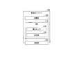
- FIG. 400 It is a figure which shows an example of the structure of the terminal apparatus 400 which concerns on embodiment. It is a figure which shows an example of the image provided by the management server 300 which concerns on embodiment. It is a flowchart which shows an example of the flow of the process of classifying the charge / discharge station apparatus 200 in the image generation part 340 which concerns on embodiment. It is a figure which shows another example of the image provided by the management server 300 which concerns on embodiment. It is a figure which shows still another example of the image provided by the management server 300 which concerns on embodiment. It is a figure which shows still another example of the image provided by the management server 300 which concerns on embodiment.
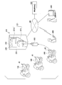
- FIG. 1 is a diagram showing an example of a usage environment of the management server 300 using the information providing device.
- the management server 300 is connected to the network NW.
- a charge / discharge station device 200 and a terminal device 400 are also connected to the network NW.
- the network NW includes, for example, the Internet, a cellular network, a Wi-Fi network, a WAN (Wide Area Network), a LAN (Local Area Network), a Bluetooth (registered trademark), and the like.
- the terminal device 400 may be a mobile terminal device such as a smartphone or a tablet terminal, may be a stationary computer, or may be included in the charge / discharge station device 200.
- each component will be described step by step.
- the charge / discharge station device 200 is a device that charges and replaces the removable battery 100 that is the drive source of the electric vehicle 10.
- the detachable battery 100 is an example of the "first battery” and the “second battery”, but the present invention is not limited to this, and the "first battery” and the “second battery” are used for applications such as a mobile portable power supply. It may be a power supply device.
- the charge / discharge station device 200 may also discharge from the detachable battery 100 in order to perform system cooperation and the like. Although one charge / discharge station device 200 is shown in FIG. 1, there are a plurality of charge / discharge station devices 200.
- FIG. 2 is a diagram showing an example of the configuration of the electric vehicle 10.
- the electric vehicle 10 is a vehicle to which the removable battery 100 can be attached and detached.
- the electric vehicle 10 is, for example, a saddle-riding vehicle that travels by the driving force of an electric motor driven by electric power supplied from a power storage unit 120 (described later) of the removable battery 100.
- the electric vehicle 10 is not limited to a saddle-riding type vehicle, and may be a vehicle of another aspect such as a four-wheeled vehicle.
- FIG. 2 it is assumed that the electric vehicle 10 can be equipped with two removable batteries 100, but the electric vehicle 10 may be equipped with an arbitrary number of removable batteries 100.
- the electric vehicle 10 may be, for example, a hybrid electric vehicle that travels by being driven by a combination of a removable battery 100 and an internal combustion engine such as a diesel engine or a gasoline engine.
- the electric vehicle 10 includes, for example, a battery connection unit 12, a vehicle control unit 14, a traveling driving force output device 16, a vehicle sensor 18, an HMI (Human Machine Interface) 20, and a GNSS (Global Navigation Satellite System) receiver. 22 and.
- the battery connection portion 12 is electrically connected to the connection portion 150 (described later) of the detachable battery 100 when the detachable battery 100 is mounted on the electric vehicle 10.
- the battery connection unit 12 is, for example, a power line connection terminal (battery terminal) for receiving power supply from the detachable battery 100, or a communication line for performing data communication between the detachable battery 100 and the vehicle control unit 14. Includes connection terminals, etc.
- the vehicle control unit 14 acquires the measurement result from the vehicle sensor 18, and acquires a value (SOC: State Of Charge) indicating the charging state of the power storage unit 120 from the BMU (Battery Management Unit) 110 (described later) of the removable battery 100. Then, the position of the electric vehicle 10 is acquired from the GNSS receiver 22. Based on the acquired data, the vehicle control unit 14 controls the traveling driving force output device 16 according to an operation on an operator (not shown) or by autonomous traveling. The vehicle control unit 14 may transmit the position information of the electric vehicle 10 acquired from the GNSS receiver 22 to the removable battery 100 via the battery connection unit 12.
- SOC State Of Charge
- the traveling driving force output device 16 includes, for example, an electric motor, an inverter, and an ECU (Electronic Control Unit) that controls the inverter.
- the ECU controls the electric power supplied from the removable battery 100 to the electric motor, for example, by controlling the inverter.
- the ECU controls the driving force (torque) output by the electric motor to the driving wheels.
- the traveling driving force output device 16 controls the output frequency of the inverter so as to be lower than the rotation speed of the driving wheels, thereby operating the electric motor as a regenerative brake and converting the braking energy of the driving wheels into electric energy.
- the removable battery 100 can be charged.
- the vehicle sensor 18 includes a speed sensor, an acceleration sensor, a rotational speed sensor, an odometer, and various other sensors mounted on the electric vehicle 10.
- the vehicle sensor 18 outputs the measurement result to the vehicle control unit 14.
- the HMI 20 outputs various information to the user of the electric vehicle 10 and accepts input operations by the user.
- the HMI 20 includes, for example, a HUD (Head Up Display), various display devices (may be a touch panel) such as a meter display unit, a speaker, and the like.
- the GNSS receiver 22 positions the electric vehicle 10 based on radio waves arriving from GNSS satellites such as GPS satellites.
- FIG. 3 is a block diagram showing an example of the configuration of the removable battery 100.
- the removable battery 100 includes, for example, a power storage unit 120, a BMU 110, and a connection unit 150. Further, the BMU 110 includes a measurement sensor 130 and a storage unit 140.
- the power storage unit 120 is, for example, an assembled battery in which a plurality of single batteries are connected in series.
- the single battery constituting the power storage unit 120 is, for example, a lithium ion secondary battery (LIB: Lithium-Ion Battery), a nickel hydrogen battery, an all-solid-state battery, or the like.
- LIB lithium ion secondary battery
- nickel hydrogen battery nickel hydrogen battery
- all-solid-state battery or the like.
- the BMU 110 controls charging and discharging of the power storage unit 120, cell balancing, abnormal detection of the power storage unit 120, derivation of the cell temperature of the power storage unit 120, derivation of the charge / discharge current of the power storage unit 120, estimation of SOC of the power storage unit 120, and the like. I do.
- the BMU 110 stores the abnormality or failure of the power storage unit 120 grasped based on the measurement result of the measurement sensor 130 in the storage unit 140 as battery status information.
- the measurement sensor 130 is a voltage sensor, a current sensor, a temperature sensor, or the like for measuring the charging state of the power storage unit 120.
- the measurement sensor 130 outputs the measurement results of the measured voltage, current, temperature, etc. to the BMU 110.
- the storage unit 140 includes a non-volatile storage device such as a flash memory.
- the storage unit 140 stores the battery status information. Further, the storage unit 140 may store the battery ID assigned to the removable battery 100.
- connection unit 150 is electrically connected to the battery connection unit 12 when the removable battery 100 is attached to the electric vehicle 10. Further, the connection portion 150 is electrically connected to the charge / discharge station device 200 when the removable battery 100 is housed in the slot portion 221 (see FIG. 1) of the charge / discharge station device 200, and the charge / discharge station device 200 is connected.
- the power storage unit 120 is charged by receiving power from the power storage unit 120.
- the connection unit 150 includes, for example, a power line connection terminal (battery terminal), a communication line connection terminal, and the like so as to correspond to the battery connection unit 12 and the charge / discharge station connection unit 225 (described later).
- FIG. 4 is a diagram showing an example of the configuration of the charge / discharge station device 200.
- the charge / discharge station device 200 includes, for example, a charging module 220, a display unit 230, an authentication unit 240, a charge / discharge station communication unit 250, and a charge / discharge station control unit 260.
- the charging module 220 includes, for example, a slot portion 221 and a charging / discharging station connecting portion 225, and a charger 227.
- the slot portion 221 is a mechanism for accepting and charging the detachable battery 100.
- the slot portion 221 includes, for example, an upper slot 221U (see FIG. 1) and a lower slot 221L (see FIG. 1).
- Each slot comprises, for example, a turntable that rotates about a vertical axis.
- a battery housing is provided on the turntable.
- the battery accommodating portion is provided, for example, in a region divided into four equal parts in a plan view of the turntable.
- An outlet is provided on the front side of the charging module 220.
- the outlet may be automatically opened when it detects the approach of the user.
- the accommodating portion located at the outlet can be replaced by rotating the turntable.
- the charging module 220 positions an empty battery accommodating portion at the outlet on the front side in a state of accepting the return of the removable battery 100 from the user.
- the battery ID of the removable battery 100 is read and transmitted to the management server 300.
- the user may authenticate to the authentication unit 240 and transmit his / her user ID to the charging / discharging station device 200.
- the user ID is also transmitted to the management server 300.
- the management server 300 collates the battery ID with the user ID, and when the collation is successful, transmits a signal permitting the supply of the detachable battery 100 to the charge / discharge station device 200.
- the charging module 220 rotates the turntable to position the battery accommodating portion accommodating the charged removable battery 100 at the outlet on the front side.
- the charge / discharge station control unit 260 transmits the user ID of the user and the battery ID of the newly rented removable battery 100 to the management server 300.
- the user authentication mechanism described so far is only an example, and any other method may be adopted.
- a charge / discharge station connection portion 225 is provided on the bottom surface of each battery accommodating portion of the slot portion 221.
- the charge / discharge station connection portion 225 is electrically connected to the connection portion 150 of the detachable battery 100 when the detachable battery 100 is housed in the battery accommodating portion.
- the charge / discharge station connection unit 225 is, for example, a communication line connection terminal for performing data communication (for example, serial communication) with a power line connection terminal (battery terminal) for supplying power to the removable battery 100. including.
- the charger 227 is connected to the power storage unit 120 of the removable battery 100 via the charge / discharge station connection unit 225.
- a power source for supplying electric power to the power storage unit 120 is connected to the charger 227.
- the charger 227 converts the electric power supplied from the power source into, for example, direct current, and supplies the electric power to the power storage unit 120.
- the display unit 230 is, for example, a touch panel.
- the authentication unit 240 uses, for example, near field communication (NFC) to read the recorded information of the NFC card (not shown) carried by the user and acquire the user ID.
- NFC near field communication
- the method for acquiring the user ID is not limited to this, and any method may be used. Authentication using the user ID does not necessarily have to be performed at each exchange.
- the charge / discharge station communication unit 250 includes a wired communication device such as a terminal adapter and an Ethernet (registered trademark) communication device, a Wi-Fi adapter, and a wireless communication device such as 3G / LTE, 4G, and Bluetooth (registered trademark). It communicates with the management server 300, the terminal device 400, etc. via the network NW.
- a wired communication device such as a terminal adapter and an Ethernet (registered trademark) communication device, a Wi-Fi adapter, and a wireless communication device such as 3G / LTE, 4G, and Bluetooth (registered trademark).
- the charge / discharge station control unit 260 includes, for example, a charge control unit 262 and a battery information upload unit 264. These components are realized, for example, by a hardware processor such as a CPU (Central Processing Unit) executing a program (software). Even if some or all of the functions are realized by hardware such as LSI (Large Scale Integration), ASIC (Application Specific Integrated Circuit), FPGA (Field-Programmable Gate Array), and GPU (Graphics Processing Unit). It may be realized by the collaboration of software and hardware.
- LSI Large Scale Integration
- ASIC Application Specific Integrated Circuit
- FPGA Field-Programmable Gate Array
- GPU Graphics Processing Unit
- the charge control unit 262 controls the charger 227 so as to charge the power storage unit 120 based on the SOC of the power storage unit 120 acquired from the removable battery 100 via the signal line.
- the SOC of the power storage unit 120 is sequentially transmitted to the charge control unit 262, for example, and the charge control unit 262 associates the battery ID of the removable battery 100 with the SOC and sends the battery information to the charge / discharge station storage unit 280.
- the charge / discharge station storage unit 280 is a RAM (RandomAccessMemory), an HDD (HardDiskDrive), a flash memory, or the like.
- the battery information upload unit 264 counts, for example, the number of removable batteries 100 (the number of charged batteries) that have been charged (or charged to a desired SOC) at an arbitrary timing, and the management server together with the station ID. Send to 300.
- this transmitted information will be referred to as upload information.
- the arbitrary timing includes, for example, the timing when the detachable battery 100 is fully charged (or charged to a desired SOC) and the timing when the detachable battery 100 is rented out. That is, any timing may be the timing at which the number of charged batteries fluctuates.
- the battery information upload unit 264 may include in the upload information the "remaining time required for charging” obtained from the charging speed, capacity, and the like for each of the detachable batteries 100 in the middle of charging. Further, the battery information upload unit 264 may include the "battery information" stored in the charge / discharge station storage unit 280 in the upload information. Further, when the battery information upload unit 264 has obtained an evaluation for the replacement service of the detachable battery 100 this time from the user, the information of this evaluation may be included in the upload information. In this case, the removable battery 100 replacement service system provides the user with content for inputting the evaluation in advance.
- the "user evaluation” includes, for example, the environment in which the charge / discharge station device 200 or the charge / discharge station device 200 is installed (installation environment) (for example, temperature and cleanliness), and the number of replaceable removable batteries 100 (charging).
- the number of completed batteries may be included, the walking distance from the position where the electric vehicle 10 is stopped to the charge / discharge station device 200, the convenience of the place where the charge / discharge station device 200 is installed, and the like may be included.
- the uploaded information is an example of "first information indicating the degree of operation in a facility that provides a service of replacing the first battery with a pre-charged second battery".
- FIG. 5 is a diagram showing an example of the configuration of the management server 300.
- the management server 300 includes, for example, a server communication unit 310, a management unit 320, a site providing unit 330, and an image generation unit 340.
- a hardware processor such as a CPU executing a program (software).
- some or all of the functions may be realized by hardware such as LSI, ASIC, FPGA, GPU, or may be realized by collaboration between software and hardware.
- the management server 300 includes a server storage unit 360.
- the server storage unit 360 is a RAM, an HDD, a flash memory, or the like.
- the combination of the server communication unit 310 and the management unit 320 is an example of the "acquisition unit”, and the combination of the site provision unit 330 and the image generation unit 340 is an example of the “providing unit”. These provide an "information providing device”. That is, in the embodiment, the "information providing device” is included in the management server 300.
- the server communication unit 310 includes a wired communication device such as a terminal adapter and an Ethernet (registered trademark) communication device, a Wi-Fi adapter, and a wireless communication device such as 3G / LTE, 4G, and Bluetooth (registered trademark), and is provided with a network NW. Communicates with the charge / discharge station device 200, the terminal device 400, and the like via the above.
- a wired communication device such as a terminal adapter and an Ethernet (registered trademark) communication device, a Wi-Fi adapter, and a wireless communication device such as 3G / LTE, 4G, and Bluetooth (registered trademark)
- 3G / LTE, 4G, and Bluetooth registered trademark
- the management unit 320 manages the user authentication at the time of replacement of the removable battery 100 as described above by using the user information management table 362.
- FIG. 6 is a diagram showing an example of the contents of the user information management table 362.
- the user information management table 362 shows the status such as renting and authenticating, the renting battery ID (assuming that a maximum of four removable batteries 100 can be rented to one user), and the user ID. This is information associated with the position of the electric vehicle 10, the required number of batteries of the electric vehicle 10, and the like.
- the management unit 320 further updates the charge / discharge station device status table 364 based on the upload information acquired from the charge / discharge station device 200.
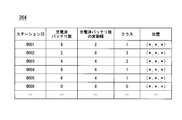
- FIG. 7 is a diagram showing an example of the contents of the charge / discharge station device state table 364.
- the charge / discharge station device status table 364 shows, for example, the number of charged batteries in the charge / discharge station device 200 indicated by the station ID, the fluctuation range of the number of charged batteries, the class (described later), and the charge / discharge with respect to the station ID. This is information associated with the position of the station device 200.
- the upload information includes the remaining time required for charging for each removable battery 100 as described above, the charge / discharge station device status table 364 shows the number of removable batteries 100 being charged and each removable battery 100.
- Information on the remaining time may be added. Further, when the upload information includes the battery information for each removable battery 100 as described above, the SOC information for each removable battery 100 may be added to the charge / discharge station device status table 364. Further, when the upload information includes the evaluation information for the exchange service as described above, the evaluation information may be added to the charge / discharge station device status table 364.
- each upload information may be added to the charge / discharge station device status table 364 without updating the upload information acquired from each charge / discharge station device 200.
- the charge / discharge station device status table 364 may record fluctuations in the uploaded information (for example, fluctuations in the number of charged batteries) in each charge / discharge station device 200 as a history.
- the site providing unit 330 has, for example, a web server function. Upon receiving the request from the terminal device 400, the site providing unit 330 displays information (for example, a web page) for displaying the corresponding content (image) on the display unit 420 (described later) of the terminal device 400 in the server communication unit 310. Is transmitted to the terminal device 400 using.
- the content (image) such as a web page transmitted by the site providing unit 330 to the terminal device 400 is an example of "second information".
- FIG. 8 is a diagram showing an example of the configuration of the terminal device 400.
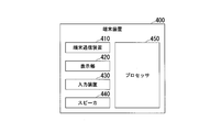
- the terminal device 400 includes a terminal communication device 410 for connecting to the network NW, a display unit 420, an input device 430 such as a keyboard, a mouse, and a touch panel, a speaker 440, and a processor 450 such as a CPU.
- the terminal device 400 may include a GNSS receiver.
- the processor executes and operates a UA (User Agent) such as a browser or an application program. In the following, it is assumed that the browser is activated in the terminal device 400.
- UA User Agent
- the browser sends an HTTP (HyperTextTransferProtocol) request including reference information such as a URL (Uniform Resource Locator) according to the operation of the user of the terminal device 400 to the DNS (Domain Name System) server.
- the DNS server replaces the domain portion with an IP (Internet Protocol) address and transmits the server to the server having the IP address (here, the management server 300).
- the site providing unit 330 transmits the web page to the transmission source terminal device 400 in response to the request acquired in this form. In this way, the management server 300 provides the web page requested by the terminal device 400.
- the web page (site) provided by the site providing unit 330 is, for example, a membership-based site in which detailed information is provided by logging in.
- the user ID managed by the management unit 320 is associated with the user ID as a member of the site, or the same ID may be used, or these are associated. It may not be.
- the image generation unit 340 generates an image in which the reference destination is embedded in the web page in response to the request received by the site providing unit 330.
- the image is, for example, an image in which information corresponding to the position of the charge / discharge station device 200 and the state of the charge / discharge station device 200 in the local map is superimposed on the local map.
- the image generation unit 340 may generate original information for causing the terminal device 400 to render or acquire the image.
- the local map is a map centered on a predetermined position cut out from the map information 366, and the predetermined position is, for example, the position of the terminal device 400.
- the position of the terminal device 400 may be inferred from the position of a relay point in the network NW accessed by the terminal device 400, or may be obtained from the terminal device 400 when the terminal device 400 includes a GNSS receiver. Good. Further, the predetermined position is not limited to the position of the terminal device 400, and may be a position designated by the user. The image is generated based on the information acquired from the charge / discharge station device state table 364.
- the map information 366 may include facility information (POI: Point Of Interest) such as convenience stores, restaurants, accommodation facilities, and various activity facilities, in addition to information on the location of the charge / discharge station device 200.
- POI Point Of Interest
- the image generation unit 340 generates an image that presents to the user the position where the charge / discharge station device 200 is installed.
- a graphic such as an icon showing the operating degree (which can be said to be the operating rate) of each charging / discharging station device 200 is arranged at a position where each charging / discharging station device 200 is installed. Therefore, the image generation unit 340 classifies the operating degree (operating rate) of the charging / discharging station device 200 according to a predetermined range (for example, classifying), and classifies the charging / discharging station device 200 installed at each position. Generate a user-recognizable image.
- the "operating degree (operating rate)” indicates, for example, the preparation status of the removable battery 100 in the charge / discharge station device 200 and the implementation availability status of the replacement service of the removable battery 100.
- the "operation degree (operation rate)” can be obtained, for example, based on the number of charged batteries included in the upload information transmitted by the charge / discharge station device 200. Further, the “operation degree (operation rate)” is based on, for example, the fluctuation range of the number of charged batteries when the upload information in each charge / discharge station device 200 is recorded as a history in the charge / discharge station device status table 364. Can be obtained.
- the “fluctuation range” is, for example, a change or rate of change in the number of charged batteries within a predetermined period (for example, 1 hour, 1 day, 6 months, 1 year, etc.) in each charge / discharge station device 200.
- This "fluctuation range” is based on the change and rate of change in the number of charged batteries within a predetermined period, for example, during the time period when the number of charged batteries decreases in a day or within a week. Learn the days when the number of batteries tends to decrease, the months and seasons when the number of charged batteries tends to decrease within a year, etc. by machine learning, deep learning, AI (Artificial Intelligence), etc. It may be used as data for.
- the image generation unit 340 uses, for example, a value representing the amount of discharge (DOD: DepthOfDischarge), a value representing the deteriorated state (SOH: StateOfHealth), and the power that can be charged and discharged.
- SOP StateOfPower
- FCC FullChargeCapacity
- the process of classifying the charge / discharge station device 200 is performed by a component other than the image generation unit 340, and the image generation unit 340 generates an image in which the user can recognize the classified classes of the charge / discharge station device 200. It may be configured to perform only.
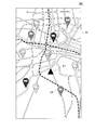
- FIG. 9 is a diagram showing an example of an image provided by the management server 300.
- the image IM1 shown in FIG. 9 is an image in which a triangular mark LT is superimposed as an icon representing the position of the terminal device 400 and a pin mark LB is superimposed as an icon representing the position of each charge / discharge station device 200 in the local map. This is an example.
- the class of each charge / discharge station device 200 classified based on the number of charged batteries is represented by the shade of color of the pin mark LB.
- the number of charged batteries in the charge / discharge station device 200 is classified into four classes, and the charge / discharge station device 200 having a large number of charged batteries has a darker pin mark LB, and the number of charged batteries is large.
- the management server 300 recommends that the charge / discharge station device 200 indicated by the dark pin mark LB be replaced with the removable battery 100. It can be presented to the user as the charging / discharging station device 200.
- the class of each charge / discharge station device 200 may be represented by different shades of the pin mark LB color as in the image IM1.
- the pin marks LB indicating the positions of the respective charge / discharge station devices 200 overlap in the image generated by the image generation unit 340.
- the image generation unit 340 is displayed in front of the pin mark LB of the charge / discharge station device 200 having a large number of charged batteries, and displayed in the back of the pin mark LB of the charge / discharge station device 200 having a small number of charged batteries. (In other words, it is displayed so as to be hidden behind the pin mark LB in the foreground).
- the charge / discharge station device 200 indicated by the dark pin mark LB due to the large number of charged batteries is represented in the foreground, and the number of charged batteries is displayed. It shows a state in which the charge / discharge station device 200 indicated by the light-colored pin mark LB is hidden so as to be hidden.
- classification process the classification process of the charge / discharge station device 200 performed when the image generation unit 340 generates an image will be described.
- the classification of the charge / discharge station device 200 in the image generation unit 340 is performed based on, for example, the degree to which the management server 300 recommends the charge / discharge station device 200 to be replaced by the removable battery 100 to the user.
- the degree to which the charge / discharge station device 200 is recommended to the user is determined by the number of charged batteries in the charge / discharge station device 200.
- the charge / discharge station device 200 having a large number of charged batteries is highly recommended as the charge / discharge station device 200 for replacing the removable battery 100 than the charge / discharge station device 200 having a small number of charged batteries. It shall be. Then, the image generation unit 340 classifies each charge / discharge station device 200 into four classes based on the number of charged batteries.
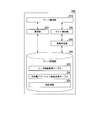
- FIG. 10 is a flowchart showing an example of a flow of processing for classifying the charge / discharge station device 200 in the image generation unit 340.
- the processing of this flowchart is executed every time the site providing unit 330 receives a request from the terminal device 400 and the image generating unit 340 generates an image IM.
- each charge / discharge station device 200 is classified into four classes based on the number of charged batteries.
- the image generation unit 340 acquires a local map centered on the position of the terminal device 400 from the map information 366 ( Step S100).
- the image generation unit 340 acquires the information of each charge / discharge station device 200 installed within the range of the acquired local map from the charge / discharge station device status table 364 (step S110).
- the image generation unit 340 classifies the charge / discharge station device 200 into the first class (step S122).
- step S120 determines that the number of charged batteries in the charge / discharge station device 200 (first charge / discharge station device 200). It is determined whether or not the number is equal to or greater than the second predetermined value (for example, "4") (step S130). When it is determined in step S130 that the number of charged batteries is equal to or greater than the second predetermined value, the image generation unit 340 classifies the charge / discharge station device 200 into the second class (step S132).
- the second predetermined value for example, "4"
- step S130 determines that the number of charged batteries in the charge / discharge station device 200 (first charge / discharge station device 200). It is determined whether or not the number is equal to or greater than the third predetermined value (for example, "2") (step S140). When it is determined in step S140 that the number of charged batteries is equal to or greater than the third predetermined value, the image generation unit 340 classifies the charge / discharge station device 200 into the third class (step S142).
- the third predetermined value for example, "2”
- step S140 if it is determined in step S140 that the number of charged batteries is not equal to or greater than the third predetermined value, the image generation unit 340 classifies the charge / discharge station device 200 into the fourth class (step S134).
- the image generation unit 340 determines whether or not all the acquired charge / discharge station devices 200 have been classified (step S150). If it is determined in step S150 that the classification of all the acquired charge / discharge station devices 200 has not been completed, the image generation unit 340 proceeds to the process in step S120. Then, the image generation unit 340 repeats the classification process (processes of steps S120 to S150) for the next acquired charge / discharge station device 200 (for example, the second charge / discharge station device 200).
- step S150 when it is determined in step S150 that the classification of all the acquired charge / discharge station devices 200 has been completed, the image generation unit 340 shifts the shades in the acquired local map according to each of the classified classes. An image in which the changed pin mark LB is superimposed on the position of each charge / discharge station device 200 is generated (step S160). The image generation unit 340 superimposes the pin mark LB of each charge / discharge station device 200 and superimposes the triangular mark LT on the position of the terminal device 400 in the local map. Then, the image generation unit 340 ends the processing of this flowchart.
- the image generation unit 340 generates the image IM1 as shown in FIG. 9, and outputs the generated IM1 to the site providing unit 330. Then, the site providing unit 330 transmits the image output by the image generating unit 340 to the terminal device 400 using the server communication unit 310. As a result, the image generated by the image generation unit 340 is displayed on the display unit 420 included in the terminal device 400, and the information on the number of charged batteries in each charge / discharge station device 200 is presented to the user. Then, the user selects the charge / discharge station device 200 to replace the removable battery 100 based on the information on the number of charged batteries in each of the presented charge / discharge station devices 200, and goes to the selected charge / discharge station device 200. be able to.
- the image generation unit 340 is installed at the position of the selected pin mark LB when any pin mark LB in the image displayed on the display unit 420 of the terminal device 400 is selected by the user.
- An image may be generated in which information on the number of charged batteries in the charging / discharging station device 200 is presented, for example, by a pop-up screen. In this case, the user can check the number of removable batteries 100 in each charge / discharge station device 200 and go to the selected charge / discharge station device 200.
- each charge / discharge station device 200 is classified based on the number of charged batteries.
- the image generation unit 340 is based on the fluctuation range of the number of charged batteries. Therefore, each charge / discharge station device 200 may be classified into classes.
- the image generation unit 340 may, for example, classify the charge / discharge station device 200 in which the fluctuation range of the number of charged batteries is less than a predetermined value into a class having a higher recommendation level.
- the image generation unit 340 may classify, for example, the charge / discharge station device 200 in which the fluctuation range of the number of charged batteries does not fall below a predetermined value into a class having a higher degree of recommendation.
- the image generation unit 340 recommends a charge / discharge station device 200 that can more stably provide a detachable battery 100 that has been charged (or has been charged to a desired SOC). It may be classified into.
- the recommended degree in the charge / discharge station device 200 is based on the fluctuation range of the number of charged batteries, for example, the time zone in the day, the day of the week, the month or season in the year.
- the image generated by the image generation unit 340 depends on the user's convenience (convenience) determined by the operating degree of each charging / discharging station device 200, the current state (operating rate, etc.) and the past usage state. It is an image showing the degree of recommendation.
- the flow when the image generation unit 340 processes the classification according to the result obtained based on the fluctuation range can be easily understood by considering the same as the processing flow in the flowchart shown in FIG. can do. Therefore, detailed description of the classification process performed by the image generation unit 340 in this case will be omitted.
- the image generation unit 340 is used for each charge / discharge station device 200.
- the total SOC of the detachable battery 100 may be calculated, and each charge / discharge station device 200 may be classified based on the calculated total SOC value.
- the image generation unit 340 may, for example, classify the charge / discharge station device 200 having a high total SOC value into a class having a higher recommendation level.
- the image generator 340 is fully charged (or charged to a desired SOC) based on the total SOC of the removable batteries 100 in the charge / discharge station device 200 instead of the number of charged batteries.
- the charge / discharge station device 200 having more removable batteries 100 may be determined, and the charge / discharge station device 200 having a higher recommendation degree may be determined based on the determination result. Further, the image generation unit 340 calculates a value obtained by dividing the total value of SOC by the number of removable batteries 100 in the charge / discharge station device 200, and classifies each charge / discharge station device 200 based on the calculated value. You may divide it.
- the flow of the classification process in the image generation unit 340 in this case can be easily understood by considering the same as the process flow in the flowchart shown in FIG. Therefore, detailed description of the classification process performed by the image generation unit 340 in this case will be omitted.
- the image generation unit 340 is used for the user's evaluation. Based on this, each charge / discharge station device 200 may be classified. At this time, the image generation unit 340 may, for example, classify the charge / discharge station device 200 having a high total or average value of the user's evaluation values into a class having a higher degree of recommendation.
- the flow of the classification process in the image generation unit 340 in this case can be easily understood by considering the same as the process flow in the flowchart shown in FIG. Therefore, detailed description of the classification process performed by the image generation unit 340 in this case will be omitted.
- each charge / discharge station device 200 is classified by receiving the request from the terminal device 400.
- the classification of the charge / discharge station device 200 is not limited to the timing after receiving the request from the terminal device 400.
- the charge / discharge station device 200 is classified at the final timing of the process in which the management unit 320 updates the charge / discharge station device status table 364 or at the timing after the update of the charge / discharge station device status table 364 is completed. You may.
- the image generation unit 340 can perform the process of step S160 on the assumption that the processes of steps S120 to S150 shown in FIG. 10 have already been completed. Since the processing flow of the image generation unit 340 in this case can be easily considered based on the processing flow in the flowchart shown in FIG. 10, detailed description thereof will be omitted.
- the conditions for classifying the charge / discharge station devices 200 such as the number of charged batteries described above are not individual conditions but may be a combination of a plurality of conditions.
- each charge / discharge station device 200 may be classified according to the respective conditions of the number of charged batteries, the total value of SOC, and the total value of the user's evaluation value.
- the degree of recommendation in each charge / discharge station device 200 was indicated by the shade of the pin mark LB.
- the method for expressing the recommended degree in each charge / discharge station device 200 may be a method other than the shading of the pin mark LB.
- the following is an example of some image IMs showing the recommended degree in each charge / discharge station device 200 by other than the shade of the pin mark LB.
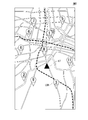
- FIG. 11 is a diagram showing another example of the image provided by the management server 300.
- the image IM2 shown in FIG. 11 is an image in which a triangular mark LT is superimposed as an icon representing the position of the terminal device 400 and a pin mark LBR is superimposed as an icon representing the position of each charge / discharge station device 200 in the local map.
- a triangular mark LT is superimposed as an icon representing the position of the terminal device 400
- a pin mark LBR is superimposed as an icon representing the position of each charge / discharge station device 200 in the local map.
- the pin mark LB in the image IM1 shown in FIG. 9 is changed to the pin mark LBR.
- the pin mark LBR is an icon in which each charge / discharge station device 200 installed in the local map is ranked in descending order of the number of charged batteries, and a number indicating the ranking is shown.
- the image IM2 can represent information corresponding to the number of charged batteries, although it is not the number of charged batteries in the charge / discharge station device 200 itself.
- the management server 300 attaches and detaches the charge / discharge station device 200 having a small number (higher rank) shown in the pin mark LBR. It can be presented to the user as a charge / discharge station device 200 that recommends replacement of the battery 100.
- the numbers shown in the pin mark LBR are not limited to the order in which the number of charged batteries is large in the charge / discharge station device 200. For example, the position of the charge / discharge station device 200 is in the order closer to the position of the terminal device 400. , The order with the highest degree of recommendation and the order with the highest evaluation by the user may be expressed.
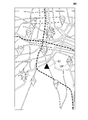
- FIG. 12 is a diagram showing still another example of the image provided by the management server 300.
- the image IM3 shown in FIG. 12 is an image in which a triangular mark LT is superimposed as an icon representing the position of the terminal device 400 and a pin mark LBS is superimposed as an icon representing the position of each charge / discharge station device 200 in the local map.
- a triangular mark LT is superimposed as an icon representing the position of the terminal device 400
- a pin mark LBS is superimposed as an icon representing the position of each charge / discharge station device 200 in the local map.
- the pin mark LB in the image IM1 shown in FIG. 9 is changed to the pin mark LBS.
- the pin mark LBS is an icon indicating the large number of charged batteries in each charge / discharge station device 200 installed in the local map.
- the image IM3 can represent information corresponding to the number of charged batteries, although it is not the number of charged batteries in the charge / discharge station device 200 itself, as in the image IM2 shown in FIG. ..
- the management server 300 recommends that the charge / discharge station device 200 having a large pin mark LBS be replaced with the removable battery 100. It can be presented to the user as a discharge station device 200.
- the size of the pin mark LBS is not limited to the large number of charged batteries in the charge / discharge station device 200, and may represent, for example, a high degree of recommendation.
- FIG. 13 is a diagram showing still another example of the image provided by the management server 300.
- the image IM4 shown in FIG. 13 is an image in which a triangular mark LT is superimposed as an icon representing the position of the terminal device 400 and a pin mark LBF is superimposed as an icon representing the position of each charge / discharge station device 200 in the local map.
- a triangular mark LT is superimposed as an icon representing the position of the terminal device 400
- a pin mark LBF is superimposed as an icon representing the position of each charge / discharge station device 200 in the local map.
- the pin mark LB in the image IM1 shown in FIG. 9 is changed to the pin mark LBF.
- the pin mark LBF is an icon showing the number of charged batteries in each charge / discharge station device 200 installed in the local map in a different shape. Due to this pin mark LBF, in the image IM4, like the image IM2 shown in FIG.
- the number of charged batteries is not the same as the number of charged batteries in the charge / discharge station device 200, but the number of charged batteries is increased. Can represent equivalent information.
- the management server 300 presents to the user the number of charged batteries in the charge / discharge station device 200 due to the difference in the shape of the pin mark LBF. be able to.
- the star-shaped pin mark LBF has the largest number of charged batteries
- the round pin mark LBF and the square pin mark LBF have the smallest number of charged batteries
- the triangular pin mark LBF has the largest number of charged batteries.
- the shape of the pin mark LBF is not limited to the large number of charged batteries in the charge / discharge station device 200, and may represent, for example, a high degree of recommendation.
- the star-shaped pin mark LBF has the highest recommendation level
- the round pin mark LBF has the lowest recommendation level
- the square pin mark LBF has the lowest recommendation level
- the triangular pin mark LBF has the lowest recommendation level.
- the discharge station device 200 may be used.
- the first battery (100) that can be attached to and detached from the moving body is precharged with the second battery.
- Acquisition units (310, 320) that acquire first information (for example, upload information) indicating the degree of operation in a facility (200) that provides a service exchanged with (100), and a terminal device (400) of a user (user).
- a providing unit (330, 340) for providing the second information (for example, IM1) and the second information displays an image (for example, IM1) showing the operating degree of each facility on the terminal device. Since the information is to be displayed on the unit (for example, the display unit 420), it is possible to support the user to smoothly use the facility for replacing the removable battery.
- the image generation unit 340 included in the management server 300 acquires a local map, and a pin mark indicating the class of each charge / discharge station device 200 installed within the range of the acquired local map.
- the configuration of generating an image IM on which the LB and the triangular mark LT are superimposed and transmitting the image IM to the terminal device 400 has been described. That is, in the information providing device of the embodiment, the configuration in which the image generation unit 340 included in the management server 300 generates an image to be presented to the user and transmits it to the terminal device 400 has been described.
- the image presented to the user is not limited to the configuration generated by the image generation unit 340 included in the management server 300.
- the image generation unit (not shown) included in the terminal device 400 generates a local map, and the range of the generated local map is based on the position and class information of the charge / discharge station device 200 transmitted by the management server 300.
- a pin mark LB indicating the position and class of the charge / discharge station device 200 may be superimposed and presented to the user.
- the management server 300 receives information on the position of the terminal device 400 together with a request from the terminal device 400, and is installed within the range of the local map generated by the terminal device 400 based on the received position of the terminal device 400.
- the charge / discharge station device 200 is selected, and only the position and class information of the selected charge / discharge station device 200 is transmitted to the terminal device 400.
- the management server 300 terminals the map information cut out from the map information 366 based on the position of the received terminal device 400. It may be transmitted to the device 400, or may be acquired by the terminal device 400 from another server (for example, a map server, etc .: not shown) different from the management server 300.
- Terminal Communication device 420 ... Display unit 430 ... Input device 440 ... Speaker 450 ... Processor NW ... Network IM1, IM2, IM3, IM4 ... Image LT ... Triangular mark LB, LBR, LBS, LBF ... Pin mark
Landscapes
- Engineering & Computer Science (AREA)
- Power Engineering (AREA)
- Transportation (AREA)
- Mechanical Engineering (AREA)
- Charge And Discharge Circuits For Batteries Or The Like (AREA)
Abstract
第1バッテリを、予め充電された第2バッテリと交換するサービスを提供する施設における稼働度合いを示す第1情報を取得する取得部と、利用者の端末装置に第2情報を提供する提供部と、を備え、第2情報は、施設ごとの稼働度合いを提示する画像を、端末装置の表示部に表示させるための情報である、情報提供装置。
Description
本発明は、情報提供装置、情報提供方法、およびプログラムに関する。
従来、バッテリ車の稼動状態データを連続的に収集し、所定時間毎に稼動状態データに基づいて、バッテリ寿命を管理するためのバッテリ情報データを算出し、この算出したバッテリ情報データを所定形式のグラフ又はデータリストとして表示し、又はプリントアウトして、バッテリ情報を管理する、バッテリ車のバッテリ情報の管理方法および管理システムが開示されている(特許文献1)。従来のバッテリ情報の管理システムでは、管理しているバッテリ情報に基づいて、バッテリ寿命を長期化できるようにユーザにリコメンド可能としている。
ところで、EV(Electric Vehicle:電気自動車)やHEV(Hybrid Electric Vehicle:ハイブリッド電気自動車)など、バッテリ(電池)から供給される電力によって駆動される電動機によって走行する電動車両では、駆動源であるバッテリの電力が消耗してきた場合、その後の走行を継続するためにバッテリの充電をする必要がある。このため、バッテリの充電の方式として、複数のユーザで着脱式のバッテリを共同利用するバッテリシェアサービスが提唱されている。バッテリシェアサービスにおいては、ユーザが消耗した着脱式バッテリを電動車両から取り外して充放電ステーションに返却し、充放電ステーションから充電済みの着脱式バッテリの貸し出しを受けて、電動車両に装着する。これにより、ユーザは、電動車両による走行を継続することができる。
しかしながら、従来の技術は、ユーザが所有しているバッテリのバッテリ寿命を長期化できるようにリコメンドするものであり、バッテリシェアサービスに対する適用に関しては検討が十分になされていない。
本発明は、このような事情を考慮してなされたものであり、着脱式バッテリを交換する施設を利用者がスムーズに利用できるように支援することができる情報提供装置、情報提供方法、およびプログラムを提供することを目的の一つとする。
この発明に係る情報提供装置、情報提供方法、およびプログラムは、以下の構成を採用した。
(1):この発明の一態様に係る情報提供装置は、第1バッテリを、予め充電された第2バッテリと交換するサービスを提供する施設における稼働度合いを示す第1情報を取得する取得部と、利用者の端末装置に第2情報を提供する提供部と、を備え、前記第2情報は、前記施設ごとの前記稼働度合いを提示する画像を、前記端末装置の表示部に表示させるための情報である、情報提供装置である。
(1):この発明の一態様に係る情報提供装置は、第1バッテリを、予め充電された第2バッテリと交換するサービスを提供する施設における稼働度合いを示す第1情報を取得する取得部と、利用者の端末装置に第2情報を提供する提供部と、を備え、前記第2情報は、前記施設ごとの前記稼働度合いを提示する画像を、前記端末装置の表示部に表示させるための情報である、情報提供装置である。
(2):上記(1)の態様において、前記第2情報は、地図における前記施設の位置に、前記施設の稼働率を示すグラフィックを配置した画像を表示させるための情報であるものである。
(3):上記(2)の態様において、前記第2情報は、前記稼働率の情報に加えて、他の要素を含むものである。
(4):上記(3)の態様において、前記他の要素は、前記施設において交換可能な前記第2バッテリの数であるものである。
(5):上記(3)または(4)の態様において、前記第2情報は、前記施設における前記稼働率の変化の履歴に基づいた画像を表示させるための情報であるものである。
(6):上記(5)の態様において、前記稼働率の変化の履歴は、前記施設において交換可能な前記第2バッテリの数の変動幅を含み、前記第2情報は、前記変動幅が所定値未満の前記施設を推奨する画像を表示させるための情報であるものである。
(7):上記(5)の態様において、前記稼働率の変化の履歴は、前記施設において交換可能な前記第2バッテリの数の変動幅を含み、前記第2情報は、前記変動幅が所定値を下回らない前記施設を推奨する画像を表示させるための情報であるものである。
(8):上記(5)の態様において、前記稼働率の変化の履歴は、前記施設の稼働率、前記施設において交換可能な前記第2バッテリの数、前記施設にある前記第2バッテリの充電状態を表す値、前記利用者による前記施設に対する評価値、前記施設の設置環境に関する情報のうち少なくとも1つ以上の過去の履歴により算出される前記利用者の利便度を含み、前記第2情報は、前記利便度に応じた前記施設を推奨する画像を表示させるための情報であるものである。
(9):上記(3)から(8)のうちいずれか一態様において、前記第2情報は、前記施設を前記利用者に推奨する度合いに基づいて、前記グラフィックの色の濃淡を変えた画像を表示させるための情報であるものである。
(10):上記(3)から(9)のうちいずれか一態様において、前記他の要素は、前記施設にある前記第2バッテリにおける充電状態を表す値を含み、前記第2情報は、前記施設にある前記第2バッテリにおける前記充電状態を表す値の合計値に基づいて、前記グラフィックの色の濃淡を変えた画像を表示させるための情報であるものである。
(11):上記(3)から(10)のうちいずれか一態様において、前記他の要素は、前記利用者による前記施設に対する評価値を含み、前記第2情報は、前記評価値に基づいて前記グラフィックの色の濃淡を変えた画像を表示させるための情報であるものである。
(12):また、本発明の一態様に係る情報提供方法は、コンピュータが、第1バッテリを、予め充電された第2バッテリと交換するサービスを提供する施設における稼働度合いを示す第1情報を取得し、利用者の端末装置に第2情報を提供し、前記第2情報は、前記施設ごとの前記稼働度合いを提示する画像を、前記端末装置の表示部に表示させるための情報である、情報提供方法である。
(13):また、本発明の一態様に係るプログラムは、コンピュータに、第1バッテリを、予め充電された第2バッテリと交換するサービスを提供する施設における稼働度合いを示す第1情報を取得させ、利用者の端末装置に第2情報を提供させ、前記第2情報は、前記施設ごとの前記稼働度合いを提示する画像を、前記端末装置の表示部に表示させるための情報である、プログラムである。
上記(1)~(13)の態様によれば、着脱式バッテリを交換する施設を利用者がスムーズに利用できるように支援することができる。
以下、図面を参照し、本発明の情報提供装置、情報提供方法、およびプログラムの実施形態について説明する。
[全体構成]
図1は、情報提供装置を利用した管理サーバ300の使用環境の一例を示す図である。管理サーバ300は、ネットワークNWに接続される。ネットワークNWには、充放電ステーション装置200や端末装置400も接続される。ネットワークNWは、例えば、インターネット、セルラー網、Wi-Fi網、WAN(Wide Area Network)、LAN(Local Area Network)、Bluetooth(登録商標)などを含む。端末装置400は、スマートフォンやタブレット端末等の携帯端末装置であってもよいし、据え置き型のコンピュータであってもよいし、充放電ステーション装置200に含まれるものであってもよい。以下、順を追って各構成要素について説明する。
図1は、情報提供装置を利用した管理サーバ300の使用環境の一例を示す図である。管理サーバ300は、ネットワークNWに接続される。ネットワークNWには、充放電ステーション装置200や端末装置400も接続される。ネットワークNWは、例えば、インターネット、セルラー網、Wi-Fi網、WAN(Wide Area Network)、LAN(Local Area Network)、Bluetooth(登録商標)などを含む。端末装置400は、スマートフォンやタブレット端末等の携帯端末装置であってもよいし、据え置き型のコンピュータであってもよいし、充放電ステーション装置200に含まれるものであってもよい。以下、順を追って各構成要素について説明する。
充放電ステーション装置200は、電動車両10の駆動源である着脱式バッテリ100の充電および交換を行う装置である。着脱式バッテリ100は、「第1バッテリ」および「第2バッテリ」の一例であるが、これに限らず、「第1バッテリ」および「第2バッテリ」は、移動型ポータブル電源などの用途に用いられる電源装置であってもよい。充放電ステーション装置200は、系統連携などを行うために着脱式バッテリ100から放電させることも行ってよい。図1では、1つの充放電ステーション装置200が示されているが、複数の充放電ステーション装置200が存在する。
[電動車両10]
図2は、電動車両10の構成の一例を示す図である。電動車両10は、着脱式バッテリ100を着脱可能な車両である。電動車両10は、例えば、着脱式バッテリ100の蓄電部120(後述)から供給される電力によって駆動される電動機の駆動力で走行する鞍乗り型の車両である。電動車両10は、鞍乗り型の車両に限られず、例えば、四輪自動車などの他の態様の車両であってよい。図2では、電動車両10が2つの着脱式バッテリ100を装着可能であるものとしているが、電動車両10は、任意の数の着脱式バッテリ100を装着可能であってもよい。また、電動車両10は、例えば、着脱式バッテリ100と、ディーゼルエンジンやガソリンエンジンなどの内燃機関とを組み合わせた駆動によって走行するハイブリッド電動車両であってもよい。
図2は、電動車両10の構成の一例を示す図である。電動車両10は、着脱式バッテリ100を着脱可能な車両である。電動車両10は、例えば、着脱式バッテリ100の蓄電部120(後述)から供給される電力によって駆動される電動機の駆動力で走行する鞍乗り型の車両である。電動車両10は、鞍乗り型の車両に限られず、例えば、四輪自動車などの他の態様の車両であってよい。図2では、電動車両10が2つの着脱式バッテリ100を装着可能であるものとしているが、電動車両10は、任意の数の着脱式バッテリ100を装着可能であってもよい。また、電動車両10は、例えば、着脱式バッテリ100と、ディーゼルエンジンやガソリンエンジンなどの内燃機関とを組み合わせた駆動によって走行するハイブリッド電動車両であってもよい。
電動車両10は、例えば、バッテリ接続部12と、車両制御部14と、走行駆動力出力装置16と、車両センサ18と、HMI(Human Machine Interface)20と、GNSS(Global Navigation Satellite System)受信機22とを備える。
バッテリ接続部12は、着脱式バッテリ100が電動車両10に装着された際に、着脱式バッテリ100の接続部150(後述)と電気的に接続される。バッテリ接続部12は、例えば、着脱式バッテリ100から電力供給を受けるための電力線の接続端子(バッテリターミナル)や、着脱式バッテリ100と車両制御部14との間でデータ通信を行うための通信線の接続端子等を含む。
車両制御部14は、車両センサ18から測定結果を取得し、着脱式バッテリ100のBMU(Battery Management Unit)110(後述)から蓄電部120の充電状態を表す値(SOC:State Of Charge)を取得し、GNSS受信機22から電動車両10の位置を取得する。車両制御部14は、取得したデータに基づき、操作子(不図示)に対する操作に応じて、或いは自律走行によって走行駆動力出力装置16を制御する。車両制御部14は、GNSS受信機22から取得した電動車両10の位置情報を、バッテリ接続部12を介して着脱式バッテリ100に送信してもよい。
走行駆動力出力装置16は、例えば、電動機と、インバータと、インバータを制御するECU(Electronic Control Unit)とを備える。ECUは、例えば、インバータを制御することによって、着脱式バッテリ100から電動機に供給される電力を制御する。これにより、ECUは、電動機が駆動輪に出力する駆動力(トルク)を制御する。また、走行駆動力出力装置16は、インバータの出力周波数を、駆動輪の回転数より低くなるように制御することにより、電動機を回生ブレーキとして動作させ、駆動輪の制動エネルギーを電気エネルギーに変換し、着脱式バッテリ100を充電することができる。
車両センサ18は、電動車両10に搭載された速度センサ、加速度センサ、回転速度センサ、オドメータ、その他各種センサを含む。車両センサ18は、測定結果を車両制御部14に出力する。
HMI20は、電動車両10のユーザに対して各種情報を出力するとともに、ユーザによる入力操作を受け付ける。HMI20は、例えば、HUD(Head Up Display)及びメーター表示部等の各種表示装置(タッチパネルであってよい)、スピーカ等を備える。
GNSS受信機22は、例えばGPS衛星などのGNSS衛星から到来する電波に基づいて電動車両10の位置を測位する。
[着脱式バッテリ100]
図3は、着脱式バッテリ100の構成の一例を示すブロック図である。着脱式バッテリ100は、例えば、蓄電部120と、BMU110と、接続部150とを備える。また、BMU110は、測定センサ130と、記憶部140とを備える。
図3は、着脱式バッテリ100の構成の一例を示すブロック図である。着脱式バッテリ100は、例えば、蓄電部120と、BMU110と、接続部150とを備える。また、BMU110は、測定センサ130と、記憶部140とを備える。
蓄電部120は、例えば、複数の単電池を直列に接続した組電池である。蓄電部120を構成する単電池は、例えば、リチウムイオン二次電池(LIB:Lithium-Ion Battery)やニッケル水素電池、全固体電池などである。
BMU110は、蓄電部120の充電や放電の制御、セルバランシング、蓄電部120の異常検出、蓄電部120のセル温度の導出、蓄電部120の充放電電流の導出、蓄電部120のSOCの推定等を行う。BMU110は、測定センサ130の測定結果に基づいて把握した蓄電部120の異常や故障などを、バッテリ状態情報として記憶部140に記憶させる。
測定センサ130は、蓄電部120の充電状態を測定するための電圧センサ、電流センサ、温度センサなどである。測定センサ130は、測定された電圧、電流、温度等の測定結果をBMU110に出力する。
記憶部140は、例えば、フラッシュメモリ等の不揮発性の記憶装置を含む。記憶部140は、バッテリ状態情報を記憶する。また、記憶部140には、着脱式バッテリ100に対して割り当てられたバッテリIDが記憶されてよい。
接続部150は、着脱式バッテリ100が電動車両10に装着された際に、バッテリ接続部12に電気的に接続される。また、接続部150は、着脱式バッテリ100が充放電ステーション装置200のスロット部221(図1参照)に収容された際に、充放電ステーション装置200に電気的に接続され、充放電ステーション装置200から電力の供給を受けて蓄電部120を充電する。接続部150は、バッテリ接続部12と充放電ステーション接続部225(後述)に対応するように、例えば、電力線の接続端子(バッテリターミナル)や、通信線の接続端子等を含む。
[充放電ステーション装置200]
図4は、充放電ステーション装置200の構成の一例を示す図である。充放電ステーション装置200は、例えば、充電モジュール220と、表示部230と、認証部240と、充放電ステーション通信部250と、充放電ステーション制御部260とを備える。
図4は、充放電ステーション装置200の構成の一例を示す図である。充放電ステーション装置200は、例えば、充電モジュール220と、表示部230と、認証部240と、充放電ステーション通信部250と、充放電ステーション制御部260とを備える。
充電モジュール220は、例えば、スロット部221と、充放電ステーション接続部225と、充電器227とを備える。スロット部221は、着脱式バッテリ100を受け入れて充電を行うための機構である。スロット部221は、例えば、上段スロット221U(図1参照)と下段スロット221L(図1参照)を備える。それぞれのスロットは、例えば鉛直軸周りに回転するターンテーブルを備える。ターンテーブル上には、バッテリ収容部が設けられる。バッテリ収容部は、例えば、ターンテーブルを平面視して4等分に仕切った領域にそれぞれ設けられる。
充電モジュール220の正面側には、取出口が設けられている。取出口は、ユーザの接近を検知すると自動的に開放状態になるようにしてもよい。取出口に位置する収容部は、ターンテーブルを回転させることにより入れ替え可能である。
充電モジュール220は、ユーザからの着脱式バッテリ100の返却を受け付ける状態において、空のバッテリ収容部を正面側の取出口に位置させる。着脱式バッテリ100がバッテリ収容部に返却されると、着脱式バッテリ100のバッテリIDが読み取られて管理サーバ300に送信される。これと並行して、ユーザは、認証部240に対して認証を行い、自身のユーザIDを充放電ステーション装置200に伝えてもよい。ユーザIDも管理サーバ300に送信される。管理サーバ300は、バッテリIDとユーザIDとの照合を行い、照合が成功した場合に、着脱式バッテリ100の供給を許可する信号を充放電ステーション装置200に送信する。これを受けて充電モジュール220は、ターンテーブルを回転させて、充電済みの着脱式バッテリ100を収容するバッテリ収容部を正面側の取出口に位置させる。これにより、ユーザは、充電済みの着脱式バッテリ100を取り出し、電動車両10に装着することができる。この貸し出しのタイミングで、充放電ステーション制御部260は、ユーザのユーザIDと、新しく貸し出された着脱式バッテリ100のバッテリIDを、管理サーバ300に送信する。なお、ここまでで説明したユーザ認証の仕組みはあくまで一例であり、任意の他の手法が採用されてもよい。
スロット部221のそれぞれのバッテリ収容部の底面には、充放電ステーション接続部225が設けられている。充放電ステーション接続部225は、着脱式バッテリ100がバッテリ収容部に収容された際に、着脱式バッテリ100の接続部150と電気的に接続される。充放電ステーション接続部225は、例えば、着脱式バッテリ100に電力を供給するための電力線の接続端子(バッテリターミナル)との間でデータ通信(例えばシリアル通信)を行うための通信線の接続端子等を含む。
充電器227は、充放電ステーション接続部225を介して、着脱式バッテリ100の蓄電部120と接続される。充電器227には、蓄電部120に電力を供給するための電源が接続されている。充電器227は、電源から供給される電力を例えば直流に変換し、蓄電部120に供給する。
表示部230は、例えば、タッチパネルである。認証部240は、例えば、近距離通信(NFC;Near Field Communication)を用いて、ユーザが携行するNFCカード(不図示)の記録情報を読取り、ユーザIDを取得する。ユーザIDを取得する手法はこれに限らず、任意の手法で行われてよい。ユーザIDを用いた認証は、必ずしも交換の度に行われる必要はない。
充放電ステーション通信部250は、ターミナルアダプターやイーサネット(登録商標)通信装置などの有線通信装置や、Wi-Fiアダプターや、3G/LTE、4G、Bluetooth(登録商標)などの無線通信装置を備え、ネットワークNWを介して管理サーバ300、端末装置400等と通信する。
充放電ステーション制御部260は、例えば、充電制御部262と、バッテリ情報アップロード部264とを備える。これらの構成要素は、例えば、CPU(Central Processing Unit)などのハードウェアプロセッサがプログラム(ソフトウェア)を実行することにより実現される。また、その機能うち一部又は全部は、LSI(Large Scale Integration)やASIC(Application Specific Integrated Circuit)、FPGA(Field-Programmable Gate Array)、GPU(Graphics Processing Unit)などのハードウェアによって実現されてもよいし、ソフトウェアとハードウェアの協働によって実現されてもよい。
充電制御部262は、着脱式バッテリ100から信号線を介して取得した蓄電部120のSOC等に基づいて、蓄電部120を充電するように充電器227を制御する。蓄電部120のSOCは、例えば、逐次、充電制御部262に伝えられ、充電制御部262は、着脱式バッテリ100のバッテリIDとSOCとを互いに対応付け、バッテリ情報として充放電ステーション記憶部280に記憶させる。充放電ステーション記憶部280は、RAM(Random Access Memory)やHDD(Hard Disk Drive)、フラッシュメモリなどである。
バッテリ情報アップロード部264は、例えば、任意のタイミングで、充電が完了した(或いは、所望のSOCまで充電された)着脱式バッテリ100の数(充電済バッテリ数)をカウントし、ステーションIDと共に管理サーバ300に送信する。以下、この送信される情報をアップロード情報と称する。任意のタイミングとは、例えば、着脱式バッテリ100の充電が完了した(或いは、所望のSOCまで充電された)タイミングと、着脱式バッテリ100の貸し出しが行われたタイミングとを含む。すなわち、任意のタイミングは、充電済バッテリの数に変動が生じたタイミングであってよい。また、バッテリ情報アップロード部264は、充電途中の着脱式バッテリ100のそれぞれに関して、充電速度と容量などから求めた「充電に必要な残り時間」をアップロード情報に含めてもよい。また、バッテリ情報アップロード部264は、充放電ステーション記憶部280に記憶している「バッテリ情報」をアップロード情報に含めてもよい。また、バッテリ情報アップロード部264は、今回の着脱式バッテリ100の交換サービスに対する評価をユーザから取得している場合、この評価の情報をアップロード情報に含めてもよい。この場合、着脱式バッテリ100の交換サービスのシステムでは、評価を入力するためのコンテンツを、予めユーザに提供している。「ユーザの評価」は、例えば、充放電ステーション装置200または充放電ステーション装置200を設置している環境(設置環境)(例えば、温度やきれいさ)、交換可能な着脱式バッテリ100の数(充電済バッテリ数)の多さ、電動車両10を停車した位置から充放電ステーション装置200までの歩行距離、充放電ステーション装置200を設置している場所の利便性などを含んでもよい。アップロード情報は、「第1バッテリを、予め充電された第2バッテリと交換するサービスを提供する施設における稼働度合いを示す第1情報」の一例である。
[管理サーバ300]
図5は、管理サーバ300の構成の一例を示す図である。管理サーバ300は、例えば、サーバ通信部310と、管理部320と、サイト提供部330と、画像生成部340とを備える。例えば、CPUなどのハードウェアプロセッサがプログラム(ソフトウェア)を実行することにより実現される。また、その機能うち一部又は全部は、LSIやASIC、FPGA、GPUなどのハードウェアによって実現されてもよいし、ソフトウェアとハードウェアの協働によって実現されてもよい。また、管理サーバ300は、サーバ記憶部360を備える。サーバ記憶部360は、RAMやHDD、フラッシュメモリなどである。サーバ通信部310と管理部320を合わせたものが「取得部」の一例であり、サイト提供部330と画像生成部340を合わせたものが「提供部」の一例である。これらが「情報提供装置」を提供する。すなわち、実施形態において、「情報提供装置」は管理サーバ300に包含されるものである。
図5は、管理サーバ300の構成の一例を示す図である。管理サーバ300は、例えば、サーバ通信部310と、管理部320と、サイト提供部330と、画像生成部340とを備える。例えば、CPUなどのハードウェアプロセッサがプログラム(ソフトウェア)を実行することにより実現される。また、その機能うち一部又は全部は、LSIやASIC、FPGA、GPUなどのハードウェアによって実現されてもよいし、ソフトウェアとハードウェアの協働によって実現されてもよい。また、管理サーバ300は、サーバ記憶部360を備える。サーバ記憶部360は、RAMやHDD、フラッシュメモリなどである。サーバ通信部310と管理部320を合わせたものが「取得部」の一例であり、サイト提供部330と画像生成部340を合わせたものが「提供部」の一例である。これらが「情報提供装置」を提供する。すなわち、実施形態において、「情報提供装置」は管理サーバ300に包含されるものである。
サーバ通信部310は、ターミナルアダプターやイーサネット(登録商標)通信装置などの有線通信装置や、Wi-Fiアダプターや、3G/LTE、4G、Bluetooth(登録商標)などの無線通信装置を備え、ネットワークNWを介して充放電ステーション装置200、端末装置400等と通信する。
管理部320は、ユーザ情報管理テーブル362を用いて、前述したように着脱式バッテリ100の交換時におけるユーザ認証を管理する。図6は、ユーザ情報管理テーブル362の内容の一例を示す図である。ユーザ情報管理テーブル362は、ユーザIDに対して、貸出中、認証中などのステータス、貸出中バッテリID(一人のユーザに最大で4個の着脱式バッテリ100を貸し出すことを想定している)、電動車両10の位置、電動車両10の必要バッテリ数などが対応付けられた情報である。
管理部320は、更に、充放電ステーション装置200から取得したアップロード情報に基づいて、充放電ステーション装置状態テーブル364を更新する。図7は、充放電ステーション装置状態テーブル364の内容の一例を示す図である。充放電ステーション装置状態テーブル364は、例えば、ステーションIDに対して、ステーションIDが示す充放電ステーション装置200における充電済バッテリ数と、充電済バッテリ数の変動幅と、クラス(後述)と、充放電ステーション装置200の位置とが対応付けられた情報である。前述のようにアップロード情報に着脱式バッテリ100ごとの充電に必要な残り時間が含まれる場合、充放電ステーション装置状態テーブル364には、充電中の着脱式バッテリ100の数と着脱式バッテリ100ごとの残り時間の情報が追加されてもよい。また、前述のようにアップロード情報に着脱式バッテリ100ごとのバッテリ情報が含まれる場合、充放電ステーション装置状態テーブル364には、それぞれの着脱式バッテリ100ごとのSOCの情報が追加されてもよい。また、前述のようにアップロード情報に交換サービスに対する評価の情報が含まれる場合、充放電ステーション装置状態テーブル364には、評価の情報が追加されてもよい。
なお、充放電ステーション装置状態テーブル364は、それぞれの充放電ステーション装置200から取得したアップロード情報を更新せずに、それぞれのアップロード情報が追加されてもよい。言い換えれば、充放電ステーション装置状態テーブル364は、それぞれの充放電ステーション装置200におけるアップロード情報の変動(例えば、充電済バッテリ数の変動)を履歴として記録しておいてもよい。
サイト提供部330は、例えば、ウェブサーバ機能を有する。サイト提供部330は、端末装置400からのリクエストを受け付けると、対応するコンテンツ(画像)を端末装置400の表示部420(後述)に表示させるための情報(例えばウェブページ)を、サーバ通信部310を用いて端末装置400に送信する。サイト提供部330が端末装置400に送信する、例えばウェブページなどのコンテンツ(画像)は、「第2情報」の一例である。
[端末装置400]
ここで、端末装置400について説明する。図8は、端末装置400の構成の一例を示す図である。端末装置400は、ネットワークNWに接続するための端末通信装置410、表示部420、キーボードやマウス、タッチパネルなどの入力装置430、スピーカ440、CPUなどのプロセッサ450などを備える。端末装置400は、GNSS受信機を備えてもよい。端末装置400では、プロセッサにより、ブラウザやアプリケーションプログラムなどのUA(User Agent)が実行され、動作する。以下では、端末装置400においてブラウザが起動するものとして説明する。
ここで、端末装置400について説明する。図8は、端末装置400の構成の一例を示す図である。端末装置400は、ネットワークNWに接続するための端末通信装置410、表示部420、キーボードやマウス、タッチパネルなどの入力装置430、スピーカ440、CPUなどのプロセッサ450などを備える。端末装置400は、GNSS受信機を備えてもよい。端末装置400では、プロセッサにより、ブラウザやアプリケーションプログラムなどのUA(User Agent)が実行され、動作する。以下では、端末装置400においてブラウザが起動するものとして説明する。
ブラウザは、端末装置400の利用者の操作に応じたURL(Uniform Resource Locator)などの参照情報を含むHTTP(Hyper Text Transfer Protocol)リクエストをDNS(Domain Name System)サーバに送信する。DNSサーバは、ドメイン部分をIP(Internet Protocol)アドレスに置換して、当該IPアドレスを有するサーバ(ここでは管理サーバ300)に送信する。サイト提供部330は、このような形で取得されたリクエストに応じて、ウェブページを送信元の端末装置400に送信する。このようにして、端末装置400によりリクエストされたウェブページを管理サーバ300が提供する。サイト提供部330が提供するウェブページ(サイト)は、例えば、ログインによって詳細情報が提供される会員制のサイトである。この場合、管理部320が管理するユーザIDと、サイトの会員としてのユーザIDとの対応付けがされており、或いは同一のIDが使用されるようにしてもよいし、これらが対応付けられていないものとしてもよい。
図5に戻り、画像生成部340は、サイト提供部330が受け付けたリクエストに応じて、ウェブページに参照先が埋め込まれる画像を生成する。その画像は、例えば、ローカル地図に対して、ローカル地図内の充放電ステーション装置200の位置および充放電ステーション装置200の状態に応じた情報を重畳させた画像である。画像生成部340は、係る画像を端末装置400にレンダリングまたは取得させるための元情報を生成するものであってもよい。ローカル地図とは、地図情報366から切り出した、所定位置を中心とした地図であり、所定位置とは、例えば端末装置400の位置である。端末装置400の位置は、例えば、端末装置400がアクセスするネットワークNW内の中継点の位置から推測されてもよいし、端末装置400がGNSS受信機を備える場合は端末装置400から取得されてもよい。また、所定位置は、端末装置400の位置に限らず、ユーザが指定した位置であってもよい。係る画像は、充放電ステーション装置状態テーブル364から取得される情報に基づいて生成される。
地図情報366には、充放電ステーション装置200の位置の情報の他、コンビニエンスストア、飲食店、宿泊施設、各種アクティビティ施設などの施設情報(POI:Point Of Interest)が含まれてもよい。
画像生成部340は、充放電ステーション装置200が設置されている位置をユーザに提示する画像を生成する。この画像には、充放電ステーション装置200ごとの稼働度合い(稼働率ともいえる)を示す、例えばアイコンなどのグラフィックが、それぞれの充放電ステーション装置200が設置されている位置に配置される。このため、画像生成部340は、充放電ステーション装置200における稼働度合い(稼働率)を所定範囲ごとに分類(例えばクラス分け)し、それぞれの位置に設置されている充放電ステーション装置200のクラスをユーザが認識可能な画像を生成する。「稼働度合い(稼働率)」とは、例えば、充放電ステーション装置200における着脱式バッテリ100の準備状況や、着脱式バッテリ100の交換サービスの実施可否状況を表すものである。「稼働度合い(稼働率)」は、例えば、充放電ステーション装置200により送信されたアップロード情報に含まれる充電済バッテリ数に基づいて求めることができる。また、「稼働度合い(稼働率)」は、例えば、充放電ステーション装置状態テーブル364にそれぞれの充放電ステーション装置200におけるアップロード情報が履歴として記録されている場合、充電済バッテリ数の変動幅に基づいて求めることができる。「変動幅」は、例えば、それぞれの充放電ステーション装置200における所定期間(例えば、1時間、1日、半年、1年など)内の充電済バッテリ数の変化や変化率である。この「変動幅」は、所定期間内の充電済バッテリ数の変化や変化率に基づいて、例えば、1日の内で充電済バッテリ数が少なくなる時間帯や、1週間の内で充電済バッテリ数が少なくなる傾向が表れる曜日、1年の内で充電済バッテリ数が少なくなる傾向が表れる月や季節などを、例えば、機械学習、ディープラーニング、AI(Artificial Intelligence;人工知能)などによって学習するためのデータとして用いてもよい。
なお、画像生成部340は、「変動幅」の学習において、例えば、放電量を表す値(DOD:Depth Of Discharge)、劣化状態を表す値(SOH:State Of Health)、充放電可能な電力を表す値(SOP:State Of Power)、満充電時の容量を表す値(FCC:Full Charge Capacity)など、着脱式バッテリ100が備える蓄電部120の状態を表す複数の要素のデータをSOCに加えて用いた統計的な解析を行ってもよい。
なお、充放電ステーション装置200のクラス分けの処理は、画像生成部340以外の構成要素が行い、画像生成部340は、クラス分けされた充放電ステーション装置200のクラスをユーザが認識できる画像の生成のみを行う構成であってもよい。
[画像の第1例]
図9は、管理サーバ300が提供する画像の一例を示す図である。図9に示した画像IM1は、ローカル地図内に、端末装置400の位置を表すアイコンとして三角マークLTを重畳し、それぞれの充放電ステーション装置200の位置を表すアイコンとしてピンマークLBを重畳した画像の一例である。画像IM1では、充電済バッテリ数に基づいてクラス分けしたそれぞれの充放電ステーション装置200のクラスを、ピンマークLBの色の濃淡によって表している。例えば、画像IM1では、充放電ステーション装置200における充電済バッテリ数を4つのクラスにクラス分けし、充電済バッテリ数が多い充放電ステーション装置200ほど濃い色のピンマークLBとし、充電済バッテリ数が少ない充放電ステーション装置200ほど薄い色のピンマークLBとしている。この画像IM1を端末装置400に送信して表示部420に表示させることによって、管理サーバ300は、濃い色のピンマークLBで示された充放電ステーション装置200を、着脱式バッテリ100の交換を推奨する充放電ステーション装置200としてユーザに提示することができる。なお、それぞれの充放電ステーション装置200のクラスは、画像IM1のようにピンマークLBの色の濃淡で表す代わりに、ピンマークLBの色自体を異ならせることによって表してもよい。
図9は、管理サーバ300が提供する画像の一例を示す図である。図9に示した画像IM1は、ローカル地図内に、端末装置400の位置を表すアイコンとして三角マークLTを重畳し、それぞれの充放電ステーション装置200の位置を表すアイコンとしてピンマークLBを重畳した画像の一例である。画像IM1では、充電済バッテリ数に基づいてクラス分けしたそれぞれの充放電ステーション装置200のクラスを、ピンマークLBの色の濃淡によって表している。例えば、画像IM1では、充放電ステーション装置200における充電済バッテリ数を4つのクラスにクラス分けし、充電済バッテリ数が多い充放電ステーション装置200ほど濃い色のピンマークLBとし、充電済バッテリ数が少ない充放電ステーション装置200ほど薄い色のピンマークLBとしている。この画像IM1を端末装置400に送信して表示部420に表示させることによって、管理サーバ300は、濃い色のピンマークLBで示された充放電ステーション装置200を、着脱式バッテリ100の交換を推奨する充放電ステーション装置200としてユーザに提示することができる。なお、それぞれの充放電ステーション装置200のクラスは、画像IM1のようにピンマークLBの色の濃淡で表す代わりに、ピンマークLBの色自体を異ならせることによって表してもよい。
なお、例えば、複数の充放電ステーション装置200が近くに設置されている場合、画像生成部340が生成する画像では、それぞれの充放電ステーション装置200の位置を表すピンマークLBが重なることになる。この場合、画像生成部340は、充電済バッテリ数が多い充放電ステーション装置200のピンマークLBほど手前に表示され、充電済バッテリ数が少ない充放電ステーション装置200のピンマークLBほど奥に表示される(言い換えれば、手前のピンマークLBに隠れるように表示される)ような画像を生成する。画像IM1では、領域R1内の2つの充放電ステーション装置200のうち、充電済バッテリ数が多いことにより濃い色のピンマークLBで示される充放電ステーション装置200が手前に表され、充電済バッテリ数が少ないことにより薄い色のピンマークLBで示される充放電ステーション装置200が隠れるように表示されている状態を示している。
[クラス分け処理]
ここで、画像生成部340が画像を生成する際に行う充放電ステーション装置200のクラス分け処理について説明する。画像生成部340における充放電ステーション装置200のクラス分けは、例えば、管理サーバ300が着脱式バッテリ100の交換する充放電ステーション装置200をユーザに推奨する度合いに基づいて行う。以下の説明においては、ユーザに充放電ステーション装置200を推奨する度合い(以下、推奨度合い)が、充放電ステーション装置200にある充電済バッテリ数によって定められているものとする。例えば、充電済バッテリ数が多い充放電ステーション装置200の方が、充電済バッテリ数が少ない充放電ステーション装置200よりも、着脱式バッテリ100の交換をする充放電ステーション装置200としての推奨度合いが高いものとする。そして、画像生成部340は、充電済バッテリ数に基づいて、それぞれの充放電ステーション装置200を4つのクラスにクラス分けするものとする。
ここで、画像生成部340が画像を生成する際に行う充放電ステーション装置200のクラス分け処理について説明する。画像生成部340における充放電ステーション装置200のクラス分けは、例えば、管理サーバ300が着脱式バッテリ100の交換する充放電ステーション装置200をユーザに推奨する度合いに基づいて行う。以下の説明においては、ユーザに充放電ステーション装置200を推奨する度合い(以下、推奨度合い)が、充放電ステーション装置200にある充電済バッテリ数によって定められているものとする。例えば、充電済バッテリ数が多い充放電ステーション装置200の方が、充電済バッテリ数が少ない充放電ステーション装置200よりも、着脱式バッテリ100の交換をする充放電ステーション装置200としての推奨度合いが高いものとする。そして、画像生成部340は、充電済バッテリ数に基づいて、それぞれの充放電ステーション装置200を4つのクラスにクラス分けするものとする。
図10は、画像生成部340における充放電ステーション装置200のクラス分けの処理の流れの一例を示すフローチャートである。本フローチャートの処理は、サイト提供部330が端末装置400からのリクエストを受け付け、画像生成部340が画像IMを生成するごとに実行される。なお、本フローチャートの処理は、充電済バッテリ数に基づいて、それぞれの充放電ステーション装置200を4つのクラスにクラス分けするものとする。
端末装置400からのリクエストを受け付けたことを表す情報がサイト提供部330により出力されると、画像生成部340は、地図情報366から、端末装置400の位置を中心としたローカル地図を取得する(ステップS100)。
続いて、画像生成部340は、取得したローカル地図の範囲内に設置されたそれぞれの充放電ステーション装置200の情報を、充放電ステーション装置状態テーブル364から取得する(ステップS110)。
続いて、画像生成部340は、取得した充放電ステーション装置200(最初は、1つ目の充放電ステーション装置200)における充電済バッテリ数が、第1所定値(例えば、「6個」)以上であるか否かを判定する(ステップS120)。ステップS120において、充電済バッテリ数が第1所定値以上であると判定した場合、画像生成部340は、この充放電ステーション装置200のクラスを第1クラスに分類する(ステップS122)。
一方、ステップS120において、充電済バッテリ数が第1所定値以上ではないと判定した場合、画像生成部340は、この充放電ステーション装置200(1つ目の充放電ステーション装置200)における充電済バッテリ数が、第2所定値(例えば、「4個」)以上であるか否かを判定する(ステップS130)。ステップS130において、充電済バッテリ数が第2所定値以上であると判定した場合、画像生成部340は、この充放電ステーション装置200のクラスを第2クラスに分類する(ステップS132)。
一方、ステップS130において、充電済バッテリ数が第2所定値以上ではないと判定した場合、画像生成部340は、この充放電ステーション装置200(1つ目の充放電ステーション装置200)における充電済バッテリ数が、第3所定値(例えば、「2個」)以上であるか否かを判定する(ステップS140)。ステップS140において、充電済バッテリ数が第3所定値以上であると判定した場合、画像生成部340は、この充放電ステーション装置200のクラスを第3クラスに分類する(ステップS142)。
一方、ステップS140において、充電済バッテリ数が第3所定値以上ではないと判定した場合、画像生成部340は、この充放電ステーション装置200のクラスを第4クラスに分類する(ステップS134)。
続いて、画像生成部340は、取得した全ての充放電ステーション装置200のクラス分けが終了したか否かを判定する(ステップS150)。ステップS150において、取得した全ての充放電ステーション装置200のクラス分けが終了していないと判定した場合、画像生成部340は、処理をステップS120に進める。そして、画像生成部340は、取得した次の充放電ステーション装置200(例えば、2つ目の充放電ステーション装置200)に対するクラス分けの処理(ステップS120~ステップS150の処理)を繰り返す。
一方、ステップS150において、取得した全ての充放電ステーション装置200のクラス分けが終了したと判定した場合、画像生成部340は、取得したローカル地図内に、クラス分けしたそれぞれのクラスに応じて濃淡を変えたピンマークLBを、それぞれの充放電ステーション装置200の位置に重畳した画像を生成する(ステップS160)。なお、画像生成部340は、それぞれの充放電ステーション装置200のピンマークLBの重畳とともに、ローカル地図内の端末装置400の位置に、三角マークLTを重畳する。そして、画像生成部340は、本フローチャートの処理を終了する。
このようにして画像生成部340は、図9に示したような画像IM1を生成し、生成したIM1をサイト提供部330に出力する。そして、サイト提供部330は、画像生成部340により出力された画像を、サーバ通信部310を用いて端末装置400に送信する。これにより、端末装置400が備える表示部420に画像生成部340が生成した画像が表示され、それぞれの充放電ステーション装置200における充電済バッテリ数の情報が、ユーザに提示される。そして、ユーザは、提示されたそれぞれの充放電ステーション装置200における充電済バッテリ数の情報に基づいて着脱式バッテリ100を交換する充放電ステーション装置200を選択し、選択した充放電ステーション装置200に出向くことができる。
なお、画像生成部340は、端末装置400の表示部420に表示された画像内のいずれかのピンマークLBがユーザによって選択された場合に、選択されたピンマークLBの位置に設置されている充放電ステーション装置200における充電済バッテリ数の情報を、例えばポップアップ画面によって提示する画像を生成してもよい。この場合、ユーザは、それぞれの充放電ステーション装置200にある着脱式バッテリ100の数を確認し、選択した充放電ステーション装置200に出向くことができる。
なお、図10に示したクラス分けの処理のフローチャートでは、充電済バッテリ数に基づいてそれぞれの充放電ステーション装置200をクラス分けした。しかし、例えば、充放電ステーション装置状態テーブル364にそれぞれの充放電ステーション装置200における充電済バッテリ数の変動が履歴として記録されている場合、画像生成部340は、充電済バッテリ数の変動幅に基づいて、それぞれの充放電ステーション装置200をクラス分けしてもよい。このとき、画像生成部340は、例えば、充電済バッテリ数の変動幅が所定値未満である充放電ステーション装置200を、推奨度合いがより高いクラスに分類するようにしてもよい。また、画像生成部340は、例えば、充電済バッテリ数の変動幅が所定値を下回らない充放電ステーション装置200を、推奨度合いがより高いクラスに分類するようにしてもよい。例えば、画像生成部340は、充電が完了した(或いは、所望のSOCまで充電された)着脱式バッテリ100をより安定して提供することができる充放電ステーション装置200を、推奨度合いがより高いクラスに分類するようにしてもよい。ここで、充放電ステーション装置200における推奨度合いは、充電済バッテリ数の変動幅に基づいて、例えば、1日の内の時間帯や、1週間の内の曜日、1年の内の月や季節など、充電済バッテリ数が少なくなる傾向を統計的に解析した結果に応じて異なるものであってもよい。これにより、画像生成部340が生成する画像は、充放電ステーション装置200ごとの稼働度合いと、現状(稼働率等)と過去の利用状態とより決定されるユーザの利便性(利便度)に応じた推奨度合いを表す画像となる。なお、この場合において変動幅に基づいて得られる結果に応じて画像生成部340がクラス分けの処理する場合の流れは、図10に示したフローチャートにおける処理の流れと同様に考えることによって容易に理解することができる。従って、この場合に画像生成部340が行うクラス分けの処理に関する詳細な説明は省略する。
また、例えば、充放電ステーション装置状態テーブル364にそれぞれの充放電ステーション装置200にある着脱式バッテリ100ごとのSOCの情報が記録されている場合、画像生成部340は、充放電ステーション装置200ごとに着脱式バッテリ100のSOCの合計を算出し、算出したSOCの合計値に基づいて、それぞれの充放電ステーション装置200をクラス分けしてもよい。このとき、画像生成部340は、例えば、SOCの合計値が高い充放電ステーション装置200を、推奨度合いがより高いクラスに分類するようにしてもよい。例えば、画像生成部340は、充電済バッテリ数の代わりに、充放電ステーション装置200にある着脱式バッテリ100のSOCの合計値に基づいて、充電が完了した(或いは、所望のSOCまで充電された)着脱式バッテリ100がより多くある充放電ステーション装置200を判定し、この判定結果に基づいて、推奨度合いがより高い充放電ステーション装置200を決定するようにしてもよい。また、画像生成部340は、SOCの合計値を充放電ステーション装置200にある着脱式バッテリ100の数で除算した値を算出し、算出した値に基づいて、それぞれの充放電ステーション装置200をクラス分けしてもよい。なお、この場合の画像生成部340におけるクラス分けの処理の流れも、図10に示したフローチャートにおける処理の流れと同様に考えることによって容易に理解することができる。従って、この場合に画像生成部340が行うクラス分けの処理に関する詳細な説明は省略する。
また、例えば、充放電ステーション装置状態テーブル364にそれぞれの充放電ステーション装置200における着脱式バッテリ100の交換サービスに対するユーザの評価の情報が記録されている場合、画像生成部340は、ユーザの評価に基づいて、それぞれの充放電ステーション装置200をクラス分けしてもよい。このとき、画像生成部340は、例えば、ユーザの評価値の合計や平均値が高い充放電ステーション装置200を、推奨度合いがより高いクラスに分類するようにしてもよい。なお、この場合の画像生成部340におけるクラス分けの処理の流れも、図10に示したフローチャートにおける処理の流れと同様に考えることによって容易に理解することができる。従って、この場合に画像生成部340が行うクラス分けの処理に関する詳細な説明は省略する。
また、図10に示したクラス分けの処理のフローチャートでは、端末装置400からのリクエストを受け付けたことにより、それぞれの充放電ステーション装置200のクラス分けを行っていた。しかし、充放電ステーション装置200のクラス分けは、端末装置400からのリクエストを受け付けた後のタイミングに限定されるものではない。例えば、充放電ステーション装置200のクラス分けは、管理部320が充放電ステーション装置状態テーブル364を更新する処理の最後のタイミングや、充放電ステーション装置状態テーブル364の更新が終了した後のタイミングで行ってもよい。これにより、画像生成部340は、図10に示したステップS120~ステップS150の処理はすでに終了しているものとして、ステップS160の処理を行うことができる。なお、この場合における画像生成部340の処理の流れも、図10に示したフローチャートにおける処理の流れに基づいて容易に考えることができるため、詳細な説明は省略する。
なお、上述した充電済バッテリ数などの充放電ステーション装置200をクラス分けするための条件は、それぞれ単独の条件ではなく、複数の条件を組み合わせてもよい。例えば、充電済バッテリ数と、SOCの合計値と、ユーザの評価値の合計とのそれぞれの条件を合わせて、それぞれの充放電ステーション装置200をクラス分けしてもよい。
なお、図9に示した画像IM1では、ピンマークLBの濃淡によって、それぞれの充放電ステーション装置200における推奨度合いを表していた。しかし、それぞれの充放電ステーション装置200における推奨度合いを表す方法は、ピンマークLBの濃淡以外の方法であってもよい。以下に、ピンマークLBの濃淡以外によってそれぞれの充放電ステーション装置200における推奨度合いを表すいくつかの画像IMの例を示す。
[画像の第2例]
図11は、管理サーバ300が提供する画像の別の一例を示す図である。図11に示した画像IM2は、ローカル地図内に、端末装置400の位置を表すアイコンとして三角マークLTを重畳し、それぞれの充放電ステーション装置200の位置を表すアイコンとしてピンマークLBRを重畳した画像の一例である。画像IM2では、図9に示した画像IM1におけるピンマークLBが、ピンマークLBRに変わっている。ピンマークLBRは、ローカル地図内に設置されたそれぞれの充放電ステーション装置200において充電済バッテリ数が多い順に順位付けし、その順位を表す数字が示されたアイコンである。このピンマークLBRによって、画像IM2では、充放電ステーション装置200にある充電済バッテリ数そのものではないが、充電済バッテリ数に相当する情報を表すことができる。この画像IM2を端末装置400に送信して表示部420に表示させることによって、管理サーバ300は、ピンマークLBR内に示された数字が小さい(順位が高い)充放電ステーション装置200を、着脱式バッテリ100の交換を推奨する充放電ステーション装置200としてユーザに提示することができる。なお、ピンマークLBRに示す数字は、充放電ステーション装置200において充電済バッテリ数が多い順位に限定されるものではなく、例えば、充放電ステーション装置200の位置が端末装置400の位置から近い順や、推奨度合いの高い順、ユーザの評価が高い順を表してもよい。
図11は、管理サーバ300が提供する画像の別の一例を示す図である。図11に示した画像IM2は、ローカル地図内に、端末装置400の位置を表すアイコンとして三角マークLTを重畳し、それぞれの充放電ステーション装置200の位置を表すアイコンとしてピンマークLBRを重畳した画像の一例である。画像IM2では、図9に示した画像IM1におけるピンマークLBが、ピンマークLBRに変わっている。ピンマークLBRは、ローカル地図内に設置されたそれぞれの充放電ステーション装置200において充電済バッテリ数が多い順に順位付けし、その順位を表す数字が示されたアイコンである。このピンマークLBRによって、画像IM2では、充放電ステーション装置200にある充電済バッテリ数そのものではないが、充電済バッテリ数に相当する情報を表すことができる。この画像IM2を端末装置400に送信して表示部420に表示させることによって、管理サーバ300は、ピンマークLBR内に示された数字が小さい(順位が高い)充放電ステーション装置200を、着脱式バッテリ100の交換を推奨する充放電ステーション装置200としてユーザに提示することができる。なお、ピンマークLBRに示す数字は、充放電ステーション装置200において充電済バッテリ数が多い順位に限定されるものではなく、例えば、充放電ステーション装置200の位置が端末装置400の位置から近い順や、推奨度合いの高い順、ユーザの評価が高い順を表してもよい。
[画像の第3例]
図12は、管理サーバ300が提供する画像のさらに別の一例を示す図である。図12に示した画像IM3は、ローカル地図内に、端末装置400の位置を表すアイコンとして三角マークLTを重畳し、それぞれの充放電ステーション装置200の位置を表すアイコンとしてピンマークLBSを重畳した画像の一例である。画像IM3では、図9に示した画像IM1におけるピンマークLBが、ピンマークLBSに変わっている。ピンマークLBSは、ローカル地図内に設置されたそれぞれの充放電ステーション装置200にある充電済バッテリ数の多さを大きさで示すアイコンである。このピンマークLBSによって、画像IM3では、図11に示した画像IM2と同様に、充放電ステーション装置200にある充電済バッテリ数そのものではないが、充電済バッテリ数に相当する情報を表すことができる。この画像IM3を端末装置400に送信して表示部420に表示させることによって、管理サーバ300は、ピンマークLBSの大きさが大きい充放電ステーション装置200を、着脱式バッテリ100の交換を推奨する充放電ステーション装置200としてユーザに提示することができる。なお、ピンマークLBSの大きさは、充放電ステーション装置200にある充電済バッテリ数の多さに限定されるものではなく、例えば、推奨度合いの高さを表してもよい。
図12は、管理サーバ300が提供する画像のさらに別の一例を示す図である。図12に示した画像IM3は、ローカル地図内に、端末装置400の位置を表すアイコンとして三角マークLTを重畳し、それぞれの充放電ステーション装置200の位置を表すアイコンとしてピンマークLBSを重畳した画像の一例である。画像IM3では、図9に示した画像IM1におけるピンマークLBが、ピンマークLBSに変わっている。ピンマークLBSは、ローカル地図内に設置されたそれぞれの充放電ステーション装置200にある充電済バッテリ数の多さを大きさで示すアイコンである。このピンマークLBSによって、画像IM3では、図11に示した画像IM2と同様に、充放電ステーション装置200にある充電済バッテリ数そのものではないが、充電済バッテリ数に相当する情報を表すことができる。この画像IM3を端末装置400に送信して表示部420に表示させることによって、管理サーバ300は、ピンマークLBSの大きさが大きい充放電ステーション装置200を、着脱式バッテリ100の交換を推奨する充放電ステーション装置200としてユーザに提示することができる。なお、ピンマークLBSの大きさは、充放電ステーション装置200にある充電済バッテリ数の多さに限定されるものではなく、例えば、推奨度合いの高さを表してもよい。
[画像の第4例]
図13は、管理サーバ300が提供する画像のさらに別の一例を示す図である。図13に示した画像IM4は、ローカル地図内に、端末装置400の位置を表すアイコンとして三角マークLTを重畳し、それぞれの充放電ステーション装置200の位置を表すアイコンとしてピンマークLBFを重畳した画像の一例である。画像IM4では、図9に示した画像IM1におけるピンマークLBが、ピンマークLBFに変わっている。ピンマークLBFは、ローカル地図内に設置されたそれぞれの充放電ステーション装置200にある充電済バッテリ数を形の違いで示すアイコンである。このピンマークLBFによって、画像IM4では、図11に示した画像IM2および図12に示した画像IM3と同様に、充放電ステーション装置200にある充電済バッテリ数そのものではないが、充電済バッテリ数に相当する情報を表すことができる。この画像IM4を端末装置400に送信して表示部420に表示させることによって、管理サーバ300は、ピンマークLBFの形の違いにより、充放電ステーション装置200にある充電済バッテリ数をユーザに提示することができる。例えば、画像IM4では、星形のピンマークLBFが最も充電済バッテリ数が多く、丸形のピンマークLBF、四角形のピンマークLBFの順に充電済バッテリ数が少なくなり、三角形のピンマークLBFが最も充電済バッテリ数が少ない充放電ステーション装置200として、ユーザに提示している。なお、ピンマークLBFの形は、充放電ステーション装置200にある充電済バッテリ数の多さに限定されるものではなく、例えば、推奨度合いの高さを表してもよい。この場合、例えば、星形のピンマークLBFが最も推奨度合いが高く、丸形のピンマークLBF、四角形のピンマークLBFの順に推奨度合いが低くなり、三角形のピンマークLBFが最も推奨度合いが低い充放電ステーション装置200としてもよい。
図13は、管理サーバ300が提供する画像のさらに別の一例を示す図である。図13に示した画像IM4は、ローカル地図内に、端末装置400の位置を表すアイコンとして三角マークLTを重畳し、それぞれの充放電ステーション装置200の位置を表すアイコンとしてピンマークLBFを重畳した画像の一例である。画像IM4では、図9に示した画像IM1におけるピンマークLBが、ピンマークLBFに変わっている。ピンマークLBFは、ローカル地図内に設置されたそれぞれの充放電ステーション装置200にある充電済バッテリ数を形の違いで示すアイコンである。このピンマークLBFによって、画像IM4では、図11に示した画像IM2および図12に示した画像IM3と同様に、充放電ステーション装置200にある充電済バッテリ数そのものではないが、充電済バッテリ数に相当する情報を表すことができる。この画像IM4を端末装置400に送信して表示部420に表示させることによって、管理サーバ300は、ピンマークLBFの形の違いにより、充放電ステーション装置200にある充電済バッテリ数をユーザに提示することができる。例えば、画像IM4では、星形のピンマークLBFが最も充電済バッテリ数が多く、丸形のピンマークLBF、四角形のピンマークLBFの順に充電済バッテリ数が少なくなり、三角形のピンマークLBFが最も充電済バッテリ数が少ない充放電ステーション装置200として、ユーザに提示している。なお、ピンマークLBFの形は、充放電ステーション装置200にある充電済バッテリ数の多さに限定されるものではなく、例えば、推奨度合いの高さを表してもよい。この場合、例えば、星形のピンマークLBFが最も推奨度合いが高く、丸形のピンマークLBF、四角形のピンマークLBFの順に推奨度合いが低くなり、三角形のピンマークLBFが最も推奨度合いが低い充放電ステーション装置200としてもよい。
上記に述べたとおり、実施形態の情報提供装置を利用した管理サーバ300によれば、移動体(例えば、電動車両10)に着脱可能な第1バッテリ(100)を、予め充電された第2バッテリ(100)と交換するサービスを提供する施設(200)における稼働度合いを示す第1情報(例えば、アップロード情報)を取得する取得部(310、320)と、利用者(ユーザ)の端末装置(400)に第2情報(例えば、IM1)を提供する提供部(330、340)と、を備え、第2情報は、施設ごとの稼働度合いを提示する画像(例えば、IM1)を、端末装置の表示部(例えば、表示部420)に表示させるための情報であるため、着脱式バッテリを交換する施設を利用者がスムーズに利用できるように支援することができる。
なお、実施形態の情報提供装置では、管理サーバ300が備える画像生成部340がローカル地図を取得し、取得したローカル地図の範囲内に設置されたそれぞれの充放電ステーション装置200のクラスを示すピンマークLBおよび三角マークLTを重畳した画像IMを生成して端末装置400に送信する構成を説明した。つまり、実施形態の情報提供装置では、管理サーバ300が備える画像生成部340が、ユーザに提示する画像を生成して端末装置400に送信する構成を説明した。情報提供装置において、ユーザに提示する画像は、管理サーバ300が備える画像生成部340が生成する構成に限定されるものではない。例えば、端末装置400が備える画像生成部(不図示)がローカル地図を生成し、管理サーバ300により送信されてきた充放電ステーション装置200の位置とクラスの情報に基づいて、生成したローカル地図の範囲内に充放電ステーション装置200の位置とクラスを示すピンマークLBを重畳してユーザに提示する構成であってもよい。この場合、管理サーバ300は、端末装置400からリクエストとともに端末装置400の位置の情報を受信し、受信した端末装置400の位置に基づいて、端末装置400が生成するローカル地図の範囲内に設置された充放電ステーション装置200を選択し、選択した充放電ステーション装置200の位置およびクラスの情報のみを端末装置400に送信する。なお、端末装置400が備える画像生成部(不図示)がローカル地図を生成する場合の地図情報は、受信した端末装置400の位置に基づいて地図情報366から切り出した地図情報を管理サーバ300が端末装置400に送信したものであってもよいし、管理サーバ300とは異なる他のサーバ(例えば、地図サーバなど:不図示)から端末装置400が取得したものであってもよい。
以上、本発明を実施するための形態について実施形態を用いて説明したが、本発明はこうした実施形態に何ら限定されるものではなく、本発明の要旨を逸脱しない範囲内において種々の変形および置換を加えることができる。
10・・・電動車両
12・・・バッテリ接続部
14・・・車両制御部
16・・・走行駆動力出力装置
18・・・車両センサ
20・・・HMI
22・・・GNSS受信機
100・・・着脱式バッテリ
110・・・BMU
120・・・蓄電部
130・・・測定センサ
140・・・記憶部
150・・・接続部
200・・・充放電ステーション装置
220・・・充電モジュール
221・・・スロット部
221U・・・上段スロット
221L・・・下段スロット
225・・・充放電ステーション接続部
227・・・充電器
230・・・表示部
240・・・認証部
250・・・充放電ステーション通信部
260・・・充放電ステーション制御部
262・・・充電制御部
264・・・バッテリ情報アップロード部
280・・・充放電ステーション記憶部
300・・・管理サーバ
310・・・サーバ通信部
320・・・管理部
330・・・サイト提供部
340・・・画像生成部
360・・・サーバ記憶部
362・・・ユーザ情報管理テーブル
364・・・充放電ステーション装置状態テーブル
366・・・地図情報
400・・・端末装置
410・・・端末通信装置
420・・・表示部
430・・・入力装置
440・・・スピーカ
450・・・プロセッサ
NW・・・ネットワーク
IM1,IM2,IM3,IM4・・・画像
LT・・・三角マーク
LB,LBR,LBS,LBF・・・ピンマーク
12・・・バッテリ接続部
14・・・車両制御部
16・・・走行駆動力出力装置
18・・・車両センサ
20・・・HMI
22・・・GNSS受信機
100・・・着脱式バッテリ
110・・・BMU
120・・・蓄電部
130・・・測定センサ
140・・・記憶部
150・・・接続部
200・・・充放電ステーション装置
220・・・充電モジュール
221・・・スロット部
221U・・・上段スロット
221L・・・下段スロット
225・・・充放電ステーション接続部
227・・・充電器
230・・・表示部
240・・・認証部
250・・・充放電ステーション通信部
260・・・充放電ステーション制御部
262・・・充電制御部
264・・・バッテリ情報アップロード部
280・・・充放電ステーション記憶部
300・・・管理サーバ
310・・・サーバ通信部
320・・・管理部
330・・・サイト提供部
340・・・画像生成部
360・・・サーバ記憶部
362・・・ユーザ情報管理テーブル
364・・・充放電ステーション装置状態テーブル
366・・・地図情報
400・・・端末装置
410・・・端末通信装置
420・・・表示部
430・・・入力装置
440・・・スピーカ
450・・・プロセッサ
NW・・・ネットワーク
IM1,IM2,IM3,IM4・・・画像
LT・・・三角マーク
LB,LBR,LBS,LBF・・・ピンマーク
Claims (13)
- 第1バッテリを、予め充電された第2バッテリと交換するサービスを提供する施設における稼働度合いを示す第1情報を取得する取得部と、
利用者の端末装置に第2情報を提供する提供部と、を備え、
前記第2情報は、前記施設ごとの前記稼働度合いを提示する画像を、前記端末装置の表示部に表示させるための情報である、
情報提供装置。 - 前記第2情報は、地図における前記施設の位置に、前記施設の稼働率を示すグラフィックを配置した画像を表示させるための情報である、
請求項1に記載の情報提供装置。 - 前記第2情報は、前記稼働率の情報に加えて、他の要素を含む、
請求項2に記載の情報提供装置。 - 前記他の要素は、前記施設において交換可能な前記第2バッテリの数である、
請求項3に記載の情報提供装置。 - 前記第2情報は、前記施設における前記稼働率の変化の履歴に基づいた画像を表示させるための情報である、
請求項3または請求項4に記載の情報提供装置。 - 前記稼働率の変化の履歴は、前記施設において交換可能な前記第2バッテリの数の変動幅を含み、
前記第2情報は、前記変動幅が所定値未満の前記施設を推奨する画像を表示させるための情報である、
請求項5に記載の情報提供装置。 - 前記稼働率の変化の履歴は、前記施設において交換可能な前記第2バッテリの数の変動幅を含み、
前記第2情報は、前記変動幅が所定値を下回らない前記施設を推奨する画像を表示させるための情報である、
請求項5に記載の情報提供装置。 - 前記稼働率の変化の履歴は、前記施設の稼働率、前記施設において交換可能な前記第2バッテリの数、前記施設にある前記第2バッテリの充電状態を表す値、前記利用者による前記施設に対する評価値、前記施設の設置環境に関する情報のうち少なくとも1つ以上の過去の履歴により算出される前記利用者の利便度を含み、
前記第2情報は、前記利便度に応じた前記施設を推奨する画像を表示させるための情報である、
請求項5に記載の情報提供装置。 - 前記第2情報は、前記施設を前記利用者に推奨する度合いに基づいて、前記グラフィックの色の濃淡を変えた画像を表示させるための情報である、
請求項3から請求項8のうちいずれか1項に記載の情報提供装置。 - 前記他の要素は、前記施設にある前記第2バッテリにおける充電状態を表す値を含み、
前記第2情報は、前記施設にある前記第2バッテリにおける前記充電状態を表す値の合計値に基づいて、前記グラフィックの色の濃淡を変えた画像を表示させるための情報である、
請求項3から請求項9のうちいずれか1項に記載の情報提供装置。 - 前記他の要素は、前記利用者による前記施設に対する評価値を含み、
前記第2情報は、前記評価値に基づいて前記グラフィックの色の濃淡を変えた画像を表示させるための情報である、
請求項3から請求項10のうちいずれか1項に記載の情報提供装置。 - コンピュータが、
第1バッテリを、予め充電された第2バッテリと交換するサービスを提供する施設における稼働度合いを示す第1情報を取得し、
利用者の端末装置に第2情報を提供し、
前記第2情報は、前記施設ごとの前記稼働度合いを提示する画像を、前記端末装置の表示部に表示させるための情報である、
情報提供方法。 - コンピュータに、
第1バッテリを、予め充電された第2バッテリと交換するサービスを提供する施設における稼働度合いを示す第1情報を取得させ、
利用者の端末装置に第2情報を提供させ、
前記第2情報は、前記施設ごとの前記稼働度合いを提示する画像を、前記端末装置の表示部に表示させるための情報である、
プログラム。
Priority Applications (2)
| Application Number | Priority Date | Filing Date | Title |
|---|---|---|---|
| JP2021530394A JPWO2021005707A1 (ja) | 2019-07-09 | 2019-07-09 | |
| PCT/JP2019/027118 WO2021005707A1 (ja) | 2019-07-09 | 2019-07-09 | 情報提供装置、情報提供方法、およびプログラム |
Applications Claiming Priority (1)
| Application Number | Priority Date | Filing Date | Title |
|---|---|---|---|
| PCT/JP2019/027118 WO2021005707A1 (ja) | 2019-07-09 | 2019-07-09 | 情報提供装置、情報提供方法、およびプログラム |
Publications (1)
| Publication Number | Publication Date |
|---|---|
| WO2021005707A1 true WO2021005707A1 (ja) | 2021-01-14 |
Family
ID=74114507
Family Applications (1)
| Application Number | Title | Priority Date | Filing Date |
|---|---|---|---|
| PCT/JP2019/027118 Ceased WO2021005707A1 (ja) | 2019-07-09 | 2019-07-09 | 情報提供装置、情報提供方法、およびプログラム |
Country Status (2)
| Country | Link |
|---|---|
| JP (1) | JPWO2021005707A1 (ja) |
| WO (1) | WO2021005707A1 (ja) |
Citations (6)
| Publication number | Priority date | Publication date | Assignee | Title |
|---|---|---|---|---|
| JP2012503468A (ja) * | 2008-09-19 | 2012-02-02 | ベター プレイス ,ゲーエムベーハー | 電気自動車の操作システム及び方法 |
| JP2014211315A (ja) * | 2013-04-17 | 2014-11-13 | 日産自動車株式会社 | ハイブリッド車両の案内装置及び案内システム |
| JP2016054641A (ja) * | 2011-12-14 | 2016-04-14 | 京セラ株式会社 | 表示端末、電力制御システム、および表示方法 |
| JP2016191860A (ja) * | 2015-03-31 | 2016-11-10 | ブラザー工業株式会社 | 周辺情報提供プログラム、周辺情報提供方法及び周辺情報提供装置 |
| JP2017091427A (ja) * | 2015-11-17 | 2017-05-25 | オムロン株式会社 | バッテリ予約装置 |
| JP2018160534A (ja) * | 2017-03-22 | 2018-10-11 | キヤノン株式会社 | リソグラフィ装置、および物品の製造方法 |
-
2019
- 2019-07-09 JP JP2021530394A patent/JPWO2021005707A1/ja active Pending
- 2019-07-09 WO PCT/JP2019/027118 patent/WO2021005707A1/ja not_active Ceased
Patent Citations (6)
| Publication number | Priority date | Publication date | Assignee | Title |
|---|---|---|---|---|
| JP2012503468A (ja) * | 2008-09-19 | 2012-02-02 | ベター プレイス ,ゲーエムベーハー | 電気自動車の操作システム及び方法 |
| JP2016054641A (ja) * | 2011-12-14 | 2016-04-14 | 京セラ株式会社 | 表示端末、電力制御システム、および表示方法 |
| JP2014211315A (ja) * | 2013-04-17 | 2014-11-13 | 日産自動車株式会社 | ハイブリッド車両の案内装置及び案内システム |
| JP2016191860A (ja) * | 2015-03-31 | 2016-11-10 | ブラザー工業株式会社 | 周辺情報提供プログラム、周辺情報提供方法及び周辺情報提供装置 |
| JP2017091427A (ja) * | 2015-11-17 | 2017-05-25 | オムロン株式会社 | バッテリ予約装置 |
| JP2018160534A (ja) * | 2017-03-22 | 2018-10-11 | キヤノン株式会社 | リソグラフィ装置、および物品の製造方法 |
Also Published As
| Publication number | Publication date |
|---|---|
| JPWO2021005707A1 (ja) | 2021-01-14 |
Similar Documents
| Publication | Publication Date | Title |
|---|---|---|
| JP7112599B2 (ja) | 情報提供装置、情報提供方法、およびプログラム | |
| US20230242009A1 (en) | Power cell tracking and optimization system | |
| JP7179990B2 (ja) | 情報提供装置、情報提供方法、およびプログラム | |
| US11740098B2 (en) | System and method for providing charging options based on electric vehicle operator activities | |
| JP7156373B2 (ja) | 電池管理装置、電池情報処理システム、及び電池情報処理方法 | |
| EP3832330A1 (en) | Estimation system, estimation device, estimation method, and storage medium | |
| WO2020027202A1 (ja) | 電力予測システム、電力予測装置、電力予測方法、プログラム、及び記憶媒体 | |
| US11511646B2 (en) | Management apparatus, management method, and program | |
| CN109816874A (zh) | 租赁费用设定装置、租赁费用设定方法及租赁费用设定系统 | |
| JP2021078175A (ja) | バッテリ交換システム、管理装置、管理方法、およびプログラム | |
| WO2020203544A1 (ja) | 情報生成装置、情報生成方法、プログラム、及び記憶媒体 | |
| KR20250145124A (ko) | 컴퓨팅 작업부하들에 대한 분산되고 신뢰할 수 없는 전기차 노드들을 위한 스케줄링 시스템 및 방법 | |
| EP3930073B1 (en) | Information processing device, information processing method, service system, program, and storage medium | |
| WO2020250435A1 (ja) | 情報処理装置、情報処理方法、およびプログラム | |
| KR20210057262A (ko) | 스마트폰 연계 전기자동차 진단 시스템 | |
| CN108810816B (zh) | 蓄电装置的信息收集系统 | |
| CN108229708B (zh) | 基于无人机的预约充电方法和装置 | |
| WO2021005707A1 (ja) | 情報提供装置、情報提供方法、およびプログラム | |
| EP4592937A1 (en) | Electronic device, server, and operating method for providing user guide for battery evaluation | |
| JP7100131B2 (ja) | バッテリシェアリングサービスの管理装置、管理方法及びプログラム | |
| US20230012850A1 (en) | Control device, disaster support system, and storage medium | |
| CN108216623B (zh) | 基于无人机的信息显示方法和装置 | |
| JP7254927B2 (ja) | 情報提供装置、情報提供方法、およびプログラム | |
| Sangeetha et al. | Remote electric vehicle battery monitoring & life cycle management system | |
| JP7717263B2 (ja) | 情報提供装置、情報提供方法、およびプログラム |
Legal Events
| Date | Code | Title | Description |
|---|---|---|---|
| 121 | Ep: the epo has been informed by wipo that ep was designated in this application |
Ref document number: 19937219 Country of ref document: EP Kind code of ref document: A1 |
|
| ENP | Entry into the national phase |
Ref document number: 2021530394 Country of ref document: JP Kind code of ref document: A |
|
| NENP | Non-entry into the national phase |
Ref country code: DE |
|
| 122 | Ep: pct application non-entry in european phase |
Ref document number: 19937219 Country of ref document: EP Kind code of ref document: A1 |