WO2021005646A1 - 遮蔽率算出装置、遮蔽率算出方法及びプログラム - Google Patents
遮蔽率算出装置、遮蔽率算出方法及びプログラム Download PDFInfo
- Publication number
- WO2021005646A1 WO2021005646A1 PCT/JP2019/026828 JP2019026828W WO2021005646A1 WO 2021005646 A1 WO2021005646 A1 WO 2021005646A1 JP 2019026828 W JP2019026828 W JP 2019026828W WO 2021005646 A1 WO2021005646 A1 WO 2021005646A1
- Authority
- WO
- WIPO (PCT)
- Prior art keywords
- nth
- voxel
- shielding rate
- point cloud
- cloud data
- Prior art date
- Legal status (The legal status is an assumption and is not a legal conclusion. Google has not performed a legal analysis and makes no representation as to the accuracy of the status listed.)
- Ceased
Links
Images





Classifications
-
- H—ELECTRICITY
- H04—ELECTRIC COMMUNICATION TECHNIQUE
- H04W—WIRELESS COMMUNICATION NETWORKS
- H04W24/00—Supervisory, monitoring or testing arrangements
- H04W24/08—Testing, supervising or monitoring using real traffic
-
- H—ELECTRICITY
- H04—ELECTRIC COMMUNICATION TECHNIQUE
- H04B—TRANSMISSION
- H04B1/00—Details of transmission systems, not covered by a single one of groups H04B3/00 - H04B13/00; Details of transmission systems not characterised by the medium used for transmission
- H04B1/38—Transceivers, i.e. devices in which transmitter and receiver form a structural unit and in which at least one part is used for functions of transmitting and receiving
- H04B1/3827—Portable transceivers
- H04B1/3833—Hand-held transceivers
- H04B1/3838—Arrangements for reducing RF exposure to the user, e.g. by changing the shape of the transceiver while in use
-
- H—ELECTRICITY
- H04—ELECTRIC COMMUNICATION TECHNIQUE
- H04B—TRANSMISSION
- H04B17/00—Monitoring; Testing
- H04B17/30—Monitoring; Testing of propagation channels
- H04B17/391—Modelling the propagation channel
Definitions
- Non-Patent Document 1 a method of utilizing millimeter waves for the infrastructure of a communication network has been proposed in IEEE802.11ay (Non-Patent Document 1).
- Non-Patent Document 2 a technique for utilizing 3D point cloud data for monitoring infrastructure is being studied (Non-Patent Document 2).
- Non-Patent Document 3 as a method of determining the outlook using point cloud data. This sets a grid-like voxel of a certain size when executing the line-of-sight determination based on the point cloud data, and makes the determination.
- the point cloud data acquired by the mobile mapping system may be used.
- the point cloud density may differ depending on the distance between the moving body such as a vehicle and the shield, or the movement of the moving body such as the moving speed of the moving body. For this reason, when making a line-of-sight judgment for the Fresnel zone between radio stations, it may not be possible to correctly evaluate the proportion of shields if the judgment is made based on a uniform voxel size without considering the difference in point cloud density. is there.
- an object of the present invention is to provide a technique for improving the accuracy of evaluation in a technique for evaluating a radio wave shielding rate using point cloud data.
- One aspect of the present invention divides the Fresnel zone into a plurality of voxels having a size according to the acquisition conditions when the point cloud data indicating the obstruction of the space between the transmitting station and the receiving station is acquired. Based on the position, shape, and size of the voxel dividing portion and the shielded voxel, which is the voxel at the position indicated by the point cloud data among the plurality of voxels, the shielding rate of the radio wave from the transmitting station to the receiving station is determined. It is a shielding rate calculation device including a calculation unit for calculation.
- the Fresnel zone is divided into a plurality of voxels having a size according to the acquisition conditions when the point cloud data indicating the shielding of the space between the radio stations between the transmitting station and the receiving station is acquired.
- One aspect of the present invention is a program for operating a computer as the above-mentioned shielding rate calculation device.
- the figure which shows an example of the functional structure of the shielding rate calculation device of embodiment The first explanatory diagram explaining the method of acquiring the point cloud data in an embodiment.
- An explanatory diagram illustrating that the space between radio stations in the embodiment is divided into N subspaces by (N + 1) division planes.
- FIG. 1 is a diagram showing an example of the functional configuration of the shielding rate calculation device 1 of the embodiment.
- the shielding rate calculation device 1 is a wireless communication system including two wireless stations, and calculates the radio wave shielding rate in the wireless communication system to be analyzed by using point group data indicating a shield between the wireless stations.
- the radio wave shielding rate is the rate at which radio waves radiated from a transmitting radio station (hereinafter referred to as "transmitting station”) are shielded before reaching the receiving radio station (hereinafter referred to as "receiving station"). ..
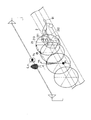
- FIG. 2 is a first explanatory diagram illustrating a method of acquiring point cloud data in the embodiment.
- FIG. 2 shows the moving body 2 and the three-dimensional laser scanner 21.
- the mobile body 2 may be, for example, a car or a drone.
- the moving body 2 moves in the direction of the arrow 91.
- the moving body 2 includes a three-dimensional laser scanner 21.
- the three-dimensional laser scanner 21 moves together with the moving body 2.
- the three-dimensional laser scanner 21 includes an emission unit 211, a reception unit 212, and a point cloud data calculation unit 213.
- the emitting unit 211 intermittently emits a laser at a constant cycle.
- the three-dimensional laser scanner 21 emits a laser into a plane (hereinafter referred to as "laser emitting surface") located at a fixed position when viewed from its own device.
- the three-dimensional laser scanner 21 changes the emission direction at a constant angular velocity so that the emission direction rotates 2 ⁇ K rad per unit time on the laser emission surface (K is a positive real number).
- K is a positive real number
- the three-dimensional laser scanner 21 changes the direction of laser emission in the direction of arrow 92. Since the three-dimensional laser scanner 21 emits the laser intermittently at a constant cycle, the laser emitted by the three-dimensional laser scanner 21 is an electromagnetic wave packet (Wave packet) P emitted intermittently at a constant cycle. is there.
- FIG. 2 shows the position of the wave packet P at a certain time t. Since the wave packet P is radiated by the three-dimensional laser scanner 21 so as to rotate 360 ° at a constant cycle, it forms a circle E. The wave packet P is reflected by the shield. Point cloud data is a set of information (hereinafter referred to as "point information") indicating the reflected position of the wave packet P and the reflected time of the wave packet P. Note that FIG. 2 shows the positions of the plurality of wave packets P emitted by the three-dimensional laser scanner 21 by the plurality of circles E for the sake of simplicity. However, in reality, the plurality of wave packets P form a spiral.
- the circle E in FIG. 2 is a shape schematically representing one winding of a spiral.
- the three-dimensional laser scanner 21 receives the reflected wave of the emitted wave packet P, and calculates the position and time when the received wave packet P is reflected based on the received time and position.
- the point cloud data is a set of information indicating the position and time when the wave packet P is reflected, which is calculated by the three-dimensional laser scanner 21.
- the moving speed of the moving body 2 affects the scan line interval sb.
- the scan line interval sb is the distance between two adjacent circles E.
- One circle E is a figure formed by the wave packet P emitted while the emission direction of the laser is rotated by 360 °. Therefore, the scan line interval sb changes according to the moving speed of the moving body 2.
- the distance between the moving body 2 and the shield affects the adjacent point spacing sa in the scan line.
- the adjacent point interval sa in the scan line is the distance between the position where the wave packet P1 is reflected and the position where the wave packet P2 is reflected.
- the wave packet P1 is one of the wave packets P
- the wave packet P2 is the wave packet P emitted next to the wave packet P1. Since the distance propagated before the wave packet P is reflected changes depending on the distance between the moving body 2 and the shield, the distance between the moving body 2 and the shield affects the adjacent point spacing sa in the scan line.
- the density of point group data is the plotted points included in the unit cell in the virtual 3D model when the position indicated by the point information is plotted in the virtual 3D space (hereinafter, "point group data points"). It is the number of.).
- FIG. 3 shows that the distance between the first shield 904 or the second shield 905 and the moving body 2 also changes with the movement of the moving body 2.
- the moving speed of the moving body 2 for acquiring the point cloud data does not have to be constant, and the moving direction does not have to be constant.
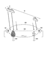
- FIG. 3 also shows a Fresnel zone 906 between the transmitting station 901 and the receiving station 902.
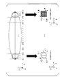
- FIG. 4 is an explanatory diagram illustrating the Fresnel zone 906.
- the Fresnel zone 906 is until the radio wave radiated from the transmitting station 901 reaches the receiving station 902 when there is no object between the transmitting station 901 and the receiving station 902 to shield the radio wave radiated from the transmitting station 901. It is a set of propagation paths. As shown in FIG. 4, the radio wave is radiated from the transmitting station 901, then spreads, then converges and reaches the receiving station 902.
- the Fresnel zone 906 is a spheroid with the local connection 903 as the axis.
- the shielding rate calculation device 1 includes a communication unit 11, a storage unit 12, and a control unit 13.
- the communication unit 11 includes a communication interface for connecting the own device to an external device.
- the communication unit 11 communicates with an external device via wireless or wired.
- the communication unit 11 acquires various information output by the external device.
- the external device may be, for example, an input terminal such as a keyboard or a touch panel that can be operated by the user, or may be a computer connected to the input terminal.
- the communication unit 11 acquires, for example, information (hereinafter referred to as “radio station information”) output by an external device indicating the positions of the transmitting station and the receiving station in the wireless communication system to be analyzed.
- the communication unit 11 outputs the acquired radio station information to the control unit 13.
- the storage unit 12 is configured by using a non-temporary computer-readable storage medium such as a magnetic hard disk device or a semiconductor storage device.
- the storage unit 12 stores, for example, point cloud data acquired in advance by the three-dimensional laser scanner 21 included in the moving body 2.
- the storage unit 12 stores information (hereinafter referred to as “acquisition condition information”) indicating acquisition conditions when the moving body 2 and the three-dimensional laser scanner 21 acquire the point cloud data.
- acquisition condition information includes information regarding the movement of the moving body 2 at the time of acquiring the point cloud data (hereinafter referred to as “moving body information”). Since the three-dimensional laser scanner 21 is fixed to the moving body 2, the information regarding the movement of the moving body 2 is the information regarding the movement of the three-dimensional laser scanner 21.
- the moving body information is, for example, information indicating a time change between the speed of the moving body 2 and the direction of movement when the point cloud data is acquired.
- the acquisition condition information includes information indicating the emission direction of the wave bundle of the laser emitted by the three-dimensional laser scanner 21 at the time of acquiring the point cloud data (hereinafter referred to as “emission direction information”).
- the acquisition condition information includes information regarding the emission timing of the laser wave packet emitted by the three-dimensional laser scanner 21 when the point cloud data is acquired (hereinafter referred to as “emission timing information”).
- the emission direction information may be, for example, information indicating a time change of the direction in which the wave packet is emitted.
- the emission direction information may be, for example, information indicating an angular velocity at which the emission direction of the wave packet rotates.
- the emission timing information may be, for example, information indicating the time when the wave packet is emitted.
- the emission timing information may be information indicating an emission interval.
- the control unit 13 is configured by using a processor such as a CPU (Central Processing Unit) and a memory.
- the control unit 13 operates by executing a program stored in the storage unit 12. More specifically, the processor included in the control unit 13 reads the program stored in the storage unit 12, and stores the read program in the memory.
- the processor included in the control unit 13 operates by executing a program stored in the memory.
- the control unit 13 controls the operation of each functional unit included in the shielding rate calculation device 1 by executing a program. By executing the program, the control unit 13 calculates the radio wave shielding rate in the wireless communication system to be analyzed, for example, based on the point cloud data.
- FIG. 5 is a diagram showing an example of the functional configuration of the control unit 13 in the embodiment.
- the control unit 13 includes an acquisition unit 131, a voxel division unit 132, and a calculation unit 133.
- the acquisition unit 131 acquires various information necessary for calculating the radio wave shielding rate acquired by the communication unit 11 and various information necessary for calculating the radio wave shielding rate stored in the storage unit 12.
- the acquisition unit 131 acquires, for example, point cloud data and acquisition condition information.
- the voxel dividing unit 132 executes a process of dividing the Fresnel zone into a plurality of voxels having a size corresponding to the acquisition condition information on the computer.
- the calculation unit 133 executes a process of calculating the radio wave shielding rate based on the position, shape, and size of the voxels at the positions indicated by the point cloud data among the plurality of voxels divided by the voxel division unit 132 on the computer.
- voxels may be pillars with a regular polygonal bottom surface.
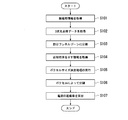
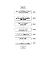
- FIG. 6 is a flowchart showing an example of a specific processing flow in which the control unit 13 of the embodiment calculates the radio wave shielding rate.
- the transmitting station 901 and the receiving station 902 in each process shown in the flowchart of FIG. 6 are the transmitting station 901 and the receiving station 902 in the virtual space representing the transmitting station 901 and the receiving station 902 in the real space.
- the acquisition unit 131 acquires radio station information (step S101). Next, the acquisition unit 131 acquires the point cloud data (step S102). Next, the voxel dividing unit 132 divides the inter-radio station space into N equal spaces (hereinafter referred to as "subspaces") in the direction from the transmitting station 901 toward the receiving station 902 (N is an integer of 1 or more). (Step S103).
- the inter-radio station space is the space between the transmitting station 901 and the receiving station 902. More specifically, the control unit 13 divides the space between radio stations into N subspaces by (N + 1) division planes.
- the dividing surface is a plane located at equal intervals in the direction along the local connection portion 903 and perpendicular to the local connection portion 903.
- the subspace closest to the transmitting station at the nth (n is an integer of 1 or more and N or less) among the N subspaces is referred to as the nth subspace.
- the number N that divides the space between radio stations may be received from an external device via the communication unit 11 or may be stored in the storage unit 12 in advance.
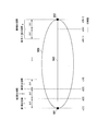
- FIG. 7 is an explanatory diagram illustrating that the space between radio stations in the embodiment is divided into N subspaces by (N + 1) division planes.
- the voxel division unit 132 generates information indicating the position, shape, and size of the approximate Fresnel zone for each partial Fresnel zone (hereinafter referred to as “approximate column information”) (step S104).
- approximately column information There are N divided Fresnel zones 906.
- the partial Fresnel zone closest to the transmitting station among the N partial Fresnel zones is referred to as the nth partial Fresnel zone. That is, the nth partial Fresnel zone is a space in which the nth subspace and the Fresnel zone 906 overlap.
- the approximate pillar is a pillar whose bottom surface is perpendicular to the local connection portion 903, and which approximates the partial Fresnel zone.
- Approximating a partial Fresnel zone means that the pillar satisfies a predetermined condition (hereinafter referred to as "partial Fresnel zone approximation condition") regarding the shape and size of the partial Fresnel zone with respect to the shape and size.
- the partial Fresnel zone approximation condition is, for example, a condition that the nth approximate column is inscribed in the nth partial Fresnel zone.
- the n-th approximate pillar is a pillar whose n-th approximate pillar is included in the n-th subspace.
- the partial Fresnel zone approximation condition may be, for example, a condition that the nth approximate column body circumscribes the nth partial Fresnel zone.
- the partial Fresnel zone approximation condition may be, for example, a condition that the cross section of the nth approximation column parallel to the bottom surface of the nth approximation column is inscribed in the central cross section of the nth partial Fresnel zone (hereinafter, "" Mid-point cross-sectional condition ").
- the central cross section is a cross section of the nth partial Fresnel zone on a plane passing through the midpoint on the local connection 903 in the nth partial Fresnel zone and perpendicular to the local connection 903.
- the bottom surface of the approximate column may be, for example, circular or a regular polygon.
- the radius of the bottom surface of the nth approximate column satisfying the midpoint cross-sectional condition is equal to the radius at the center position of the nth partial Fresnel zone.
- the shielding ratio calculation device 1 will be described by taking the case where the nth approximate column is a cylinder satisfying the midpoint cross-section condition.
- the approximate column information may indicate the position, shape, and size of the approximate column depending on, for example, the position of the apex of the approximate column.
- the approximate column information may indicate, for example, the position, shape, and size of the approximate column depending on the position, shape, and size of the center of gravity of the approximate column.
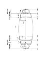
- FIG. 8 is an explanatory diagram illustrating an approximate column body in the embodiment.
- the space where the nth subspace and the Fresnel zone overlap is the nth partial Fresnel zone.
- the nth approximate column body that approximates the nth partial Fresnel zone is a cylinder C_n.
- the radius of the cylinder C_n is the radius r_n.
- the radius r_n is a radius r in which d 1 in the equation (1) satisfies the following equation (2).
- the voxel dividing unit 132 determines the voxel size for each subspace based on the acquisition condition information and the position, shape, and size of the partial Fresnel zone (step S105). More specifically, the size of the bottom surface of the voxel is determined for each subspace.
- the voxel is a pillar body whose bottom surface is perpendicular to the local connection portion 903.
- the height of the voxels in the nth subspace is equal to the length of the local connection 903 in the nth subspace.
- the process of determining the voxel size is referred to as the voxel size determination process.
- FIG. 9 is a flowchart showing an example of a specific processing flow of the voxel size determination processing in the embodiment.
- the voxel dividing unit 132 executes the process shown in FIG. 9 for each nth approximate column.
- FIG. 9 will be described by taking the case of executing the nth approximate column as an example for the sake of simplicity.
- the voxel dividing unit 132 determines which point cloud data point is the point cloud data point closest to the center of gravity of the nth approximate column (step S201).
- the point cloud data point determined to be closest to the center of gravity of the nth approximate column by the process of step S201 is referred to as a point cloud data point Pc.
- the voxel dividing unit 132 acquires the position Pr of the three-dimensional laser scanner 21 at the time Pt closest to the time indicated by the point information corresponding to the point cloud data point Pc based on the moving body information (step S202). ..
- FIG. 10 is an explanatory diagram illustrating the point cloud data point Pc and the position Pr in the embodiment.
- FIG. 10 shows that the point cloud data point Pc is located at the center of gravity of the cylinder C_n.
- FIG. 10 shows that the position Pr is on the movement path to which the moving body 2 has moved.
- the voxel dividing unit 132 calculates the velocity qr of the three-dimensional laser scanner 21 at the time Pt based on the moving body information (step S203).
- the voxel dividing unit 132 calculates the adjacent point interval sa in the scan line based on the position of the point cloud data point Pc, the position Pr, the emission direction information, and the emission timing information (step S204).
- the distance between adjacent points sa in the scan line is calculated by the following equation (3).
- ⁇ represents the measurement angle pitch.
- the measurement angle pitch ⁇ is the angular velocity at which the direction of emission of the wave packet rotates.
- R represents the distance between the point cloud data point Pc and the position Pr.
- the voxel dividing unit 132 calculates the scan line interval sb based on the emission direction information and the emission timing information (step S205).
- the scan line interval sb is calculated by the following equation (4).
- H represents the laser rotation speed.
- the laser rotation speed is the number of times that the laser scanner 21 rotates the direction of emission of the laser wave packet by 360 ° in a unit time. For example, when the dimension of the measurement angle pitch ⁇ is rad / sec, the laser rotation speed H is ⁇ / 2 ⁇ Hz.
- the voxel dividing unit 132 calculates the point cloud density pd represented by the following equation (5) (step S206).
- the point cloud density pd is the density of the point cloud data points in the nth partial Fresnel zone when the nth partial Fresnel zone is filled with a shield.
- the voxel dividing unit 132 calculates the size of the bottom surface of the voxel in the nth subspace based on the area of the bottom surface of the nth approximate column and the point cloud density pd (step S207). Specifically, the voxel dividing unit 132 acquires a value obtained by dividing the area of the bottom surface of the nth approximate column by the point cloud density pd as the size of the bottom surface of the voxel in the nth subspace.
- the area of the bottom surface of the voxel in the nth subspace is the reciprocal of the point cloud density pd, which is the density of the point cloud data points in the nth partial Fresnel zone when the nth partial Fresnel zone is filled with a shield.
- the cross section of the voxel that overlaps the nth partial Fresnel zone and is perpendicular to the local connection portion 903 includes at most one point cloud data point in the plane.
- the voxel dividing unit 132 divides the partial Fresnel zone according to the voxels having the size determined by executing the voxel sizing process (step S106).
- the calculation unit 133 calculates the radio wave shielding rate based on the position, shape, and size of the voxel (hereinafter referred to as “shielding voxel”) at the position indicated by the point cloud data among the voxels (step S107).
- shielding voxel the radio wave shielding rate based on the position, shape, and size of the voxel
- the process executed by the calculation unit 133 in step S107 is referred to as a radio wave shielding rate calculation process.
- the calculation unit 133 first determines whether or not all voxels are approximate voxels.
- An approximate column voxel is a voxel whose degree of overlap with the approximate column is greater than or equal to a predetermined degree.
- the predetermined degree is greater than 0.
- a degree of 0 means that there is no overlap.
- the predetermined degree may be different or the same for each approximate column.
- a set of approximate column voxels in which the overlap with the nth approximate column is equal to or greater than a predetermined degree is referred to as an nth approximate column voxel set.
- FIG. 11 is an explanatory diagram illustrating the relationship between the n-th approximate column voxel set and the approximate column voxel in the embodiment.
- FIG. 11 describes the relationship between the first approximate column voxel set, the Nth approximate column voxel set, and the approximate column voxel.
- the first approximate column voxel set G_1 is a set of 2 ⁇ 2 approximate column voxels having a square with one side V_1 as the bottom surface and a height of ⁇ d.
- FIG. 11 shows that the Nth approximate column voxel set G_N is a set of 16 ⁇ 16 approximate column voxels having a square with one side V_N as the bottom surface and a height of ⁇ d.
- the calculation unit 133 determines whether or not each of the approximate columnar voxels includes a point cloud data point.
- voxels determined to include point cloud data points are referred to as occlusion voxels.
- the calculation unit 133 transforms the two bottom surfaces of all the approximate pillars into a figure having the same size and shape (hereinafter referred to as a "reference figure") regardless of the nth approximate column.
- the deformation that transforms the bottom surface of the nth approximate column into a reference figure is called the nth standardized deformation.
- the calculation unit 133 also executes the nth standardized deformation on the nth approximate column voxel set.
- a set of a plurality of approximate columns after deformation (hereinafter referred to as "standard columns”) is a column.
- the shielding voxel is also deformed by the nth standardized deformation.
- the bottom surface of the shielded voxel after deformation is referred to as a shielded surface.
- the calculation unit 133 acquires the area of one bottom surface (hereinafter referred to as "shielding area") of the standard pillar in which the deformed shielding voxels do not exist in the height direction of the standard pillar. That is, the calculation unit 133 projects the bottom surfaces of all the shielded voxels from the first shielded voxel to the Nth shielded voxel onto the reference figure, and calculates the area of the figure (hereinafter referred to as “shielded figure”) projected on the reference figure. get.
- the calculation unit 133 calculates the ratio of the shielded area (that is, the area of the shielded figure) to the area of one bottom surface of the standard pillar (that is, the area of the reference figure). The calculated ratio is the radio wave shielding rate.
- FIG. 12 is an explanatory diagram illustrating a shielding voxel, a standardized deformation, and a shielding surface in the embodiment.
- FIG. 12 shows a radio wave shielding rate calculation process using the first approximate column voxel set G_1, the m approximate column voxel set (m is an integer of 2 or more and less than N) G_m, and the Nth approximate column voxel set G_N.
- the first approximate column voxel set G_1 is the same set of 2 ⁇ 2 approximate column voxels as in FIG.
- the Nth approximate column voxel set G_N is a set of 16 ⁇ 16 approximate column voxels, which is the same as in FIG.
- the m-th approximate column voxel set G_m is a set of 8 ⁇ 8 approximate column voxels.
- the sizes of the bottom surface of the first approximate columnar voxel set G_1 and the bottom surface of the mth approximate columnar voxel set G_m are different.
- the dots in the approximate column voxel are point group data points.
- FIG. 12 shows, for example, that the point cloud data point is located in the approximate column voxel at the lower right in the first approximate column voxel set G_1. Therefore, the approximate columnar voxel at the lower right of the first approximate columnar voxel set G_1 is a shielded voxel (first shielded voxel).
- FIG. 12 shows the first approximate pillar voxel set G_1 (hereinafter referred to as “first approximate pillar voxel set G′_1”) after the first standardization deformation.
- FIG. 12 shows the mth approximate columnar voxel set G_m (hereinafter referred to as “mth approximate columnar voxel set G ⁇ _m”) after the mth standardization deformation.
- FIG. 12 shows the Nth approximate column voxel set G_N (hereinafter referred to as “Nth approximate column voxel set G ′ _N”) after the Nth standardization transformation.
- the bottom surface of the first approximate columnar voxel set G'_1, the bottom surface of the m approximate columnar voxel set G'_m, and the bottom surface of the Nth approximate columnar voxel set G'_N have the same shape and are the same.
- the area The area.
- FIG. 12 shows the shielding surface A_1 of the first approximate columnar voxel set G'_1, the shielding surface A_m of the mth approximate columnar voxel set G'_m, and the shielding surface A_N of the Nth approximate columnar voxel set G'_N.
- the shielded area is the area of the area in the plane of the reference figure K excluding the non-shielded area A_0 from the reference figure K.
- the non-shielding area A_0 is an area in the plane of the reference figure K that is not the shielding surface A_1, the shielding surface A_m, or the shielding surface A_N.
- the shielding rate calculation device 1 of the embodiment configured in this way divides the Fresnel zone into a plurality of voxels having a size corresponding to the acquisition condition information indicating the conditions at the time of acquiring the point cloud data in the inter-radio station space. Then, the shielding rate calculation device 1 calculates the shielding rate of radio waves in the space between radio stations based on the position, shape, and size of the shielding voxels, which are the voxels at the positions indicated by the point cloud data among the plurality of voxels. Therefore, the shielding rate calculation device 1 configured in this way determines the shielding rate of radio waves between radio stations even when the distance between the moving body 2 and the shielding object changes when the point cloud data is acquired. It can be calculated accurately.
- the point cloud data does not necessarily have to be acquired by the three-dimensional laser scanner 21 fixed to the moving body 2.
- the point cloud data may be acquired by, for example, a camera fixed to the moving body 2.
- the emission direction information may be the direction of the camera
- the emission timing information may be the shooting timing of the camera.
- the mobile body 2 provided with the three-dimensional laser scanner 21 is an example of a point cloud data acquisition system.
- the shielded voxel deformed by the nth standardized deformation is an example of the nth shielded voxel.
- the shielded voxels in the first approximate columnar voxel set G'_1 in FIG. 12 are an example of the first shielded voxels.
- the shielded voxels in the Nth approximate columnar voxel set G'_N in FIG. 12 are an example of the Nth shielded voxels.
- the shielding rate calculation device 1 may be implemented by using a plurality of information processing devices connected so as to be able to communicate via a network.
- each functional unit included in the shielding rate calculation device 1 may be distributed and mounted in a plurality of information processing devices.
- the voxel division unit 132 and the calculation unit 133 may be mounted on different information processing devices.
- the program may be recorded on a computer-readable recording medium.
- 1 shielding rate calculation device, 11 ... communication unit, 12 ... storage unit, 13 ... control unit, 2 ... mobile body, 21 ... 3D laser scanner, 211 ... emission unit, 212 ... receiver unit, 213 ... point cloud data calculation Department, 901 ... Transmitting station, 902 ... Receiving station
Landscapes
- Engineering & Computer Science (AREA)
- Computer Networks & Wireless Communication (AREA)
- Signal Processing (AREA)
- Physics & Mathematics (AREA)
- Electromagnetism (AREA)
- Mobile Radio Communication Systems (AREA)
- Length Measuring Devices By Optical Means (AREA)
Abstract
本発明の一態様は、送信局と受信局との間の無線局間空間の遮蔽物を示す点群データを取得したときの取得条件、に応じた大きさの複数のボクセルにフレネルゾーンを分割するボクセル分割部と、前記複数のボクセルのうち前記点群データが示す位置のボクセルである遮蔽ボクセルの位置、形状及び大きさに基づいて、前記送信局から前記受信局に向かう電波の遮蔽率を算出する算出部と、を備える遮蔽率算出装置である。
Description
本発明は、遮蔽率算出装置、遮蔽率算出方法及びプログラムに関する。
従来、通信網のインフラにミリ波を活用する方法の提案がIEEE802.11ayで行われている(非特許文献1)。一方で、3次元点群データをインフラの監視に活用する技術の検討が進められている(非特許文献2)。例えば、点群データを用いた見通し判定の方法として非特許文献3がある。これは点群データに基づいた見通し判定の実行時に一定のサイズの格子状のボクセル(Voxel)を設定し判定を行う。
D. Tujkovic et al., "Changes to IEEE 802.11ay in support of mmW Distribution Network Use Cases", IEEE 802.11-17/1022r0 (July 2017), [online]、[令和1年7月1日検索]、インターネット〈URL:https://mentor.ieee.org/802.11/dcn/17/11-17-1022-00-00ay-changes-to-ieee-802-11ay-in-support-of-mmw-mesh-network-use-cases.pptx>
NTT,"設備保守作業を推進する空間状態推定技術",R&Dフォーラム2017,B-10、[online]、[令和1年7月1日検索]、インターネット〈URL:http://www.ntt.co.jp/RD/active/201702/jp/pdf_jpn/02/B-10_j.pdf>
このような見通し判定等の点群データを用いて電波の遮蔽率を評価する技術においては、モービルマッピングシステム(Mobile Mapping System:MMS)によって取得した点群データを用いる場合がある。しかしながら、このような場合、車両等の移動体と遮蔽物の間の距離、あるいは移動体の移動速度等の移動体の移動に応じて点群密度が異なる場合がある。このため、無線局間のフレネルゾーンに対して見通し判定を行う場合、点群密度の違いを考慮せずに一律のボクセルサイズの元で判定を行うと遮蔽物の割合を正しく評価できないという場合がある。
上記事情に鑑み、本発明は、点群データを用いて電波の遮蔽率を評価する技術における評価の精度を向上させる技術を提供することを目的としている。
本発明の一態様は、送信局と受信局との間の無線局間空間の遮蔽物を示す点群データを取得したときの取得条件、に応じた大きさの複数のボクセルにフレネルゾーンを分割するボクセル分割部と、前記複数のボクセルのうち前記点群データが示す位置のボクセルである遮蔽ボクセルの位置、形状及び大きさに基づいて、前記送信局から前記受信局に向かう電波の遮蔽率を算出する算出部と、を備える遮蔽率算出装置である。
本発明の一態様は、送信局と受信局との間の無線局間空間の遮蔽物を示す点群データを取得したときの取得条件、に応じた大きさの複数のボクセルにフレネルゾーンを分割するボクセル分割ステップと、
前記複数のボクセルのうち前記点群データが示す位置のボクセルである遮蔽ボクセルの位置、形状及び大きさに基づいて、前記送信局から前記受信局に向かう電波の遮蔽率を算出する算出ステップと、を有する遮蔽率算出方法である。
前記複数のボクセルのうち前記点群データが示す位置のボクセルである遮蔽ボクセルの位置、形状及び大きさに基づいて、前記送信局から前記受信局に向かう電波の遮蔽率を算出する算出ステップと、を有する遮蔽率算出方法である。
本発明の一態様は、上記の遮蔽率算出装置としてコンピュータを機能させるためのプログラムである。
本発明により、点群データを用いて電波の遮蔽率を評価する技術における評価の精度を向上させる技術を提供することが可能となる。
図1は、実施形態の遮蔽率算出装置1の機能構成の一例を示す図である。遮蔽率算出装置1は、2つの無線局を備える無線通信システムであって解析対象の無線通信システムにおける電波遮蔽率を、無線局間の遮蔽物を示す点群データを用いて算出する。電波遮蔽率は、送信側の無線局(以下「送信局」という。)から放射された電波が受信側の無線局(以下「受信局」という。)に到達する前に遮蔽される割合である。
(点群データの取得方法)
ここで、遮蔽率算出装置1が用いる点群データの取得方法について説明する。
図2は、実施形態における点群データの取得方法を説明する第1の説明図である。図2は、移動体2と3次元レーザースキャナ21とを示す。移動体2は、例えば、自動車であってもよいし、ドローンであってもよい。図2において移動体2は、矢印91の方向に移動する。移動体2は、3次元レーザースキャナ21を備える。3次元レーザースキャナ21は、移動体2とともに移動する。3次元レーザースキャナ21は、出射部211、受信部212及び点群データ算出部213を備える。出射部211は断続的に一定の周期でレーザーを出射する。出射部211は、レーザーの出射の向きを一定の角速度で回転させながらレーザーを出射する。受信部212は、出射部211が出射したレーザーの反射波を受信する。点群データ算出部213は、受信部212が受信した反射波に関する情報に基づいてレーザーが反射された位置及び時刻を算出する。
ここで、遮蔽率算出装置1が用いる点群データの取得方法について説明する。
図2は、実施形態における点群データの取得方法を説明する第1の説明図である。図2は、移動体2と3次元レーザースキャナ21とを示す。移動体2は、例えば、自動車であってもよいし、ドローンであってもよい。図2において移動体2は、矢印91の方向に移動する。移動体2は、3次元レーザースキャナ21を備える。3次元レーザースキャナ21は、移動体2とともに移動する。3次元レーザースキャナ21は、出射部211、受信部212及び点群データ算出部213を備える。出射部211は断続的に一定の周期でレーザーを出射する。出射部211は、レーザーの出射の向きを一定の角速度で回転させながらレーザーを出射する。受信部212は、出射部211が出射したレーザーの反射波を受信する。点群データ算出部213は、受信部212が受信した反射波に関する情報に基づいてレーザーが反射された位置及び時刻を算出する。
より具体的には、3次元レーザースキャナ21は、自装置から見て一定の位置に位置する平面(以下「レーザー出射面」という。)内にレーザーを出射する。3次元レーザースキャナ21は、レーザー出射面で出射の向きが単位時間当たり2πK rad回転するように(Kは正の実数)一定の角速度で出射の向きを変更する。例えば、3次元レーザースキャナ21は矢印92の方向にレーザーの出射の向きを変更する。3次元レーザースキャナ21は、レーザーを断続的に一定の周期で出射するため、3次元レーザースキャナ21が出射するレーザーは、断続的に一定の周期で出射される電磁波の波束(Wave packet)Pである。図2は、ある時刻tにおける波束Pの位置を示す。波束Pは、3次元レーザースキャナ21によって一定の周期で360°回転するように放射されるため、円Eを形成する。波束Pは、遮蔽物によって反射される。波束Pの反射された位置と波束Pの反射された時刻とを示す情報(以下「点情報」という。)の集合が点群データである。なお、図2では、説明の簡単のため複数の円Eによって3次元レーザースキャナ21が出射する複数の波束Pの位置を示している。しかしながら、実際には、複数の波束Pは螺旋を形成する。図2における円Eは、螺旋の1巻きを模式的に表した形状である。
3次元レーザースキャナ21は、出射した波束Pの反射波を受信し、受信した時刻及び位置に基づいて受信した波束Pが反射された位置及び時刻を算出する。3次元レーザースキャナ21が算出した、波束Pが反射された位置及び時刻を示す情報の集合が点群データである。
移動体2の移動速度はスキャンライン間隔sbに影響する。スキャンライン間隔sbとは、隣接する2つの円E間の距離である。レーザーの出射方向が360°回転する間に出射された波束Pによって形成された図形が1つの円Eである。そのため、移動体2の移動速度に応じて、スキャンライン間隔sbは変化する。
また、移動体2と遮蔽物の距離は、スキャンライン内の隣接点間隔saに影響する。スキャンライン内の隣接点間隔saとは、波束P1が反射された位置と波束P2が反射された位置との間の距離である。波束P1は波束Pの1つであり、波束P2は波束P1の次に出射された波束Pである。移動体2と遮蔽物の距離とに応じて、波束Pが反射されるまでに伝搬する距離が変わるため、移動体2と遮蔽物の距離は、スキャンライン内の隣接点間隔saに影響する。
このように、移動体2の移動の速さに応じてスキャンライン間隔sbが変化し、移動体2から遮蔽物までの距離に応じてスキャンライン内の隣接点間隔saが変化する。そのため、移動体2の移動の速さと移動体2から遮蔽物までの距離とに応じて、点群データの密度は異なる。点群データの密度とは、点情報が示す位置が仮想的な3次元空間内にプロットされた場合に、仮想的な3次元モデルにおける単位胞が含むプロットされた点(以下「点群データ点」という。)の数である。
図3は、実施形態における点群データの取得方法を説明する第2の説明図である。図3は、解析対象の無線通信システムにおける送信局901と受信局902とを示す。図3は、3次元レーザースキャナ21を備える移動体2が矢印91の方向に移動していることを示す。図3において矢印91の方向を向く直線は、送信局901と受信局902とを結ぶ線分(以下「局結線分903」という。)に非平行である。図3において、3次元レーザースキャナ21は移動しながらレーザーを出射している。図3は、矢印91の方向を向く直線と局結線分903とは非平行であるため、移動体2の移動によって、レーザーが出射されてから局結線分903に到達するまでの時間が変化することを示す。図3は、第1の遮蔽物904又は第2の遮蔽物905と移動体2との距離も、移動体2の移動によって変化することを示す。なお、点群データを取得する移動体2の移動の速さは一定でなくてもよいし、移動の方向も一定でなくてもよい。
また、図3は、送信局901と受信局902との間のフレネルゾーン906を示す。
図4は、フレネルゾーン906を説明する説明図である。フレネルゾーン906は、送信局901と受信局902との間に送信局901から放射された電波を遮蔽する物が無い場合に、送信局901から放射された電波が受信局902に到達するまでの伝搬経路の集合である。図4に示すように、電波は、送信局901から放射された後、広がり、その後、収束して受信局902に到達する。フレネルゾーン906は、局結線分903を軸とした回転楕円体である。局結線分903に垂直なフレネルゾーン906の断面であって送信局901から距離d1、受信局から距離d2(=D-d1)の位置に位置する断面の半径rは、以下の式(1)で表される。なお、Dは局結線分903の長さである。式(1)において、λは電波の波長である。
図4は、フレネルゾーン906を説明する説明図である。フレネルゾーン906は、送信局901と受信局902との間に送信局901から放射された電波を遮蔽する物が無い場合に、送信局901から放射された電波が受信局902に到達するまでの伝搬経路の集合である。図4に示すように、電波は、送信局901から放射された後、広がり、その後、収束して受信局902に到達する。フレネルゾーン906は、局結線分903を軸とした回転楕円体である。局結線分903に垂直なフレネルゾーン906の断面であって送信局901から距離d1、受信局から距離d2(=D-d1)の位置に位置する断面の半径rは、以下の式(1)で表される。なお、Dは局結線分903の長さである。式(1)において、λは電波の波長である。

遮蔽率算出装置1は、通信部11、記憶部12及び制御部13を備える。
通信部11は、自装置を外部装置に接続するための通信インタフェースを含んで構成される。通信部11は、無線又は有線を介して、外部装置と通信する。通信部11は、外部装置が出力した各種情報を取得する。外部装置は、例えば、ユーザが操作可能なキーボード、タッチパネル等の入力端末であってもよいし、入力端末に接続されたコンピュータであってもよい。通信部11は、例えば、外部装置が出力した、解析対象の無線通信システムにおける送信局と受信局との位置を示す情報(以下「無線局情報」という。)を取得する。通信部11は、取得した無線局情報を制御部13に出力する。
通信部11は、自装置を外部装置に接続するための通信インタフェースを含んで構成される。通信部11は、無線又は有線を介して、外部装置と通信する。通信部11は、外部装置が出力した各種情報を取得する。外部装置は、例えば、ユーザが操作可能なキーボード、タッチパネル等の入力端末であってもよいし、入力端末に接続されたコンピュータであってもよい。通信部11は、例えば、外部装置が出力した、解析対象の無線通信システムにおける送信局と受信局との位置を示す情報(以下「無線局情報」という。)を取得する。通信部11は、取得した無線局情報を制御部13に出力する。
記憶部12は、磁気ハードディスク装置や半導体記憶装置などの非一時的コンピュータ読み出し可能な記憶媒体を用いて構成される。記憶部12は、例えば、移動体2が備える3次元レーザースキャナ21によって予め取得された点群データを記憶する。記憶部12は、移動体2及び3次元レーザースキャナ21が点群データを取得したときの取得条件を示す情報(以下「取得条件情報」という。)を記憶する。取得条件情報は、点群データの取得時の移動体2の移動に関する情報(以下「移動体情報」という。)を含む。3次元レーザースキャナ21は移動体2に固定されているため、移動体2の移動に関する情報は、3次元レーザースキャナ21の移動に関する情報である。移動体情報は、例えば、点群データの取得時の移動体2の速さと移動の向きとの時間変化を示す情報である。取得条件情報は、点群データの取得時に3次元レーザースキャナ21が出射したレーザーの波束の出射の向きを示す情報(以下「出射向き情報」という。)を含む。取得条件情報は、点群データの取得時に3次元レーザースキャナ21が出射したレーザーの波束の出射のタイミングに関する情報(以下「出射タイミング情報」という。)を含む。出射向き情報は、例えば、波束が出射された向きの時間変化を示す情報であってもよい。出射向き情報は、例えば、波束の出射の向きが回転する角速度を示す情報であってもよい。出射タイミング情報は、例えば、波束が出射された時刻を示す情報であってもよい。出射タイミング情報は、出射の間隔を示す情報であってもよい。
制御部13は、CPU(Central Processing Unit)等のプロセッサやメモリを用いて構成される。制御部13は、記憶部12に記憶されているプログラムを実行することによって動作する。より具体的には、制御部13が備えるプロセッサが記憶部12に記憶されているプログラムを読み出し、読み出したプログラムをメモリに記憶させる。制御部13が備えるプロセッサは、メモリに記憶させたプログラムを実行することによって動作する。制御部13は、プログラムを実行することによって遮蔽率算出装置1が備える各機能部の動作を制御する。制御部13は、プログラムを実行することによって、例えば、点群データに基づいて、解析対象の無線通信システムにおける電波遮蔽率を算出する。
図5は、実施形態における制御部13の機能構成の一例を示す図である。制御部13は、取得部131、ボクセル分割部132及び算出部133を備える。取得部131は、通信部11が取得した電波遮蔽率の算出に必要な各種情報と、記憶部12に記憶されている電波遮蔽率の算出に必要な各種情報とを取得する。取得部131は、例えば、点群データ及び取得条件情報を取得する。ボクセル分割部132は、コンピュータ上で、取得条件情報に応じた大きさの複数のボクセルにフレネルゾーンを分割する処理を実行する。算出部133は、ボクセル分割部132が分割した複数のボクセルのうち点群データが示す位置のボクセルの位置、形状及び大きさに基づいて電波遮蔽率を算出する処理をコンピュータ上で実行する。以下、説明の簡単のため、ボクセルの形状が立方体を含む直方体である場合を例に説明する。しかし、ボクセルは底面が正多角形の柱体であってもよい。
図6は、実施形態の制御部13が電波遮蔽率を算出する具体的な処理の流れの一例を示すフローチャートである。なお、図6のフローチャートに示す各処理における送信局901及び受信局902は、実空間における送信局901及び受信局902を表す仮想空間内の送信局901及び受信局902である。
取得部131は、無線局情報を取得する(ステップS101)。次に、取得部131は、点群データを取得する(ステップS102)。次に、ボクセル分割部132は、無線局間空間を送信局901から受信局902に向かう向きにN個(Nは1以上の整数)の均等な空間(以下「部分空間」という。)に分割する(ステップS103)。無線局間空間は、送信局901と受信局902との間の空間である。より具体的には、制御部13は、無線局間の空間を(N+1)個の分割面によってN個の部分空間に分割する。分割面は、局結線分903に沿う方向に等間隔に位置し局結線分903に垂直な平面である。以下、N個の部分空間のうちn番目(nは1以上N以下の整数)に送信局に近い部分空間を第n部分空間という。なお、無線局間空間を分割する数Nは、通信部11を介して外部装置から受信してもよいし、予め記憶部12に記憶されていてもよい。
図7は、実施形態における無線局間の空間を(N+1)個の分割面によってN個の部分空間に分割することを説明する説明図である。
図7は、送信局からの距離d[1]~d[N+1]の位置に位置する(N+1)個の分割面によってフレネルゾーン906を含む無線局間の空間をN個の空間に分割することを示す。d[1]=0であり、d[N+1]=Dである。d[n+1]とd[n]との差がΔdである。d[n]の位置の分割面とd[n+1]の位置の分割面との間の空間が第n部分空間である。
図7は、送信局からの距離d[1]~d[N+1]の位置に位置する(N+1)個の分割面によってフレネルゾーン906を含む無線局間の空間をN個の空間に分割することを示す。d[1]=0であり、d[N+1]=Dである。d[n+1]とd[n]との差がΔdである。d[n]の位置の分割面とd[n+1]の位置の分割面との間の空間が第n部分空間である。
図6の説明に戻る。ボクセル分割部132は、部分フレネルゾーンごとに近似柱体の位置、形状及び大きさを示す情報(以下「近似柱体情報」という。)を生成する(ステップS104)部分フレネルゾーンは、分割面によって分割されたN個のフレネルゾーン906である。以下、N個の部分フレネルゾーンのうちn番目に送信局に近い部分フレネルゾーンを第n部分フレネルゾーンという。すなわち、第n部分フレネルゾーンは、第n部分空間とフレネルゾーン906とが重なる空間である。
近似柱体は、底面が局結線分903に垂直な柱体であって、部分フレネルゾーンを近似する柱体である。部分フレネルゾーンを近似するとは、部分フレネルゾーンの形状及び大きさに対する形状及び大きさの近さに関する所定の条件(以下「部分フレネルゾーン近似条件」という。)を柱体が満たすことを意味する。部分フレネルゾーン近似条件は、例えば、第n近似柱体が第n部分フレネルゾーンに内接する、という条件である。第n近似柱体は、第n近似柱体は第n部分空間に含まれる柱体である。部分フレネルゾーン近似条件は、例えば、第n近似柱体が第n部分フレネルゾーンに外接する、という条件であってもよい。部分フレネルゾーン近似条件は、例えば、第n近似柱体の底面に平行な第n近似柱体の断面が、第n部分フレネルゾーンの中央断面に内接する、という条件であってもよい(以下「中点断面条件」という。)。中央断面は、第n部分フレネルゾーンにおける局結線分903上の中点を通り局結線分903に垂直な面上の第n部分フレネルゾーンの断面である。近似柱体の底面は、例えば、円形であってもよいし、正多角形であってもよい。例えば、第n近似柱体の底面が円である場合には、中点断面条件を満たす第n近似柱体の底面の半径は第n部分フレネルゾーンの中央の位置における半径に等しい。以下、説明の簡単のため、第n近似柱体が中点断面条件を満たす円柱である場合を例に遮蔽率算出装置1を説明する。
近似柱体情報は、例えば、近似柱体の頂点の位置によって、近似柱体の位置、形状及び大きさを示してもよい。近似柱体情報は、例えば、近似柱体の重心の位置と、形状と、大きさとによって近似柱体の位置、形状及び大きさを示してもよい。
図8は、実施形態における近似柱体を説明する説明図である。
図8において、第n部分空間とフレネルゾーンとが重なる空間が、第n部分フレネルゾーンである。図8において、第n部分フレネルゾーンを近似する第n近似柱体が、円柱C_nである。円柱C_nの半径は半径r_nである。半径r_nは、式(1)におけるd1が以下の式(2)を満たす半径rである。
図8において、第n部分空間とフレネルゾーンとが重なる空間が、第n部分フレネルゾーンである。図8において、第n部分フレネルゾーンを近似する第n近似柱体が、円柱C_nである。円柱C_nの半径は半径r_nである。半径r_nは、式(1)におけるd1が以下の式(2)を満たす半径rである。

図6の説明に戻る。ボクセル分割部132は、取得条件情報と部分フレネルゾーンの位置、形状及び大きさとに基づいて、各部分空間ごとにボクセルの大きさを決定する(ステップS105)。より具体的には、各部分空間ごとにボクセルの底面の大きさを決定する。ボクセルは、柱体であって、底面が局結線分903に垂直である。第n部分空間のボクセルの高さは、第n部分空間における局結線分903の長さに等しい。以下、ボクセルの大きさを決定する処理をボクセルサイズ決定処理という。
図9及び図10を用いて、ステップS105におけるボクセルサイズ決定処理を説明する。
図9は、実施形態におけるボクセルサイズ決定処理の具体的な処理の流れの一例を示すフローチャートである。ボクセル分割部132は、図9に示す処理を第n近似柱体ごとに実行する。図9は、説明の簡単のため、第n近似柱体について実行する場合を例に説明する。
図9は、実施形態におけるボクセルサイズ決定処理の具体的な処理の流れの一例を示すフローチャートである。ボクセル分割部132は、図9に示す処理を第n近似柱体ごとに実行する。図9は、説明の簡単のため、第n近似柱体について実行する場合を例に説明する。
ボクセル分割部132は、第n近似柱体の重心に最も近い点群データ点がいずれの点群データ点であるかを判定する(ステップS201)。以下、ステップS201の処理によって第n近似柱体の重心に最も近いと判定された点群データ点を点群データ点Pcという。次に、ボクセル分割部132は、移動体情報に基づいて、点群データ点Pcに対応する点情報が示す時刻に最も近い時刻Ptにおける3次元レーザースキャナ21の位置Prを取得する(ステップS202)。
図10は、実施形態における点群データ点Pcと位置Prとを説明する説明図である。図10は、点群データ点Pcは、円柱C_nの重心に位置することを示す。図10は、位置Prが移動体2が移動した移動経路上にあることを示す。
図9の説明に戻る。次にボクセル分割部132は、移動体情報に基づいて、時刻Ptにおける3次元レーザースキャナ21の速度qrを算出する(ステップS203)。
次にボクセル分割部132は、点群データ点Pcの位置と、位置Prと、出射向き情報及び出射タイミング情報とに基づいて、スキャンライン内の隣接点間隔saを算出する(ステップS204)。スキャンライン内の隣接点間隔saは、以下の式(3)によって算出される。
次にボクセル分割部132は、点群データ点Pcの位置と、位置Prと、出射向き情報及び出射タイミング情報とに基づいて、スキャンライン内の隣接点間隔saを算出する(ステップS204)。スキャンライン内の隣接点間隔saは、以下の式(3)によって算出される。

式(3)において、ωは、計測角度ピッチを表す。計測角度ピッチωは、波束の出射の向きが回転する角速度である。式(3)において、Rは、点群データ点Pcと位置Prとの間の距離を表す。
次にボクセル分割部132は、出射向き情報及び出射タイミング情報に基づいてスキャンライン間隔sbを算出する(ステップS205)。スキャンライン間隔sbは、以下の式(4)によって算出される。

式(4)において、Hはレーザー回転数を表す。レーザー回転数は、単位時間にレーザースキャナ21がレーザーの波束の出射の向きを360°回転させる回数である。例えば、計測角度ピッチωの次元がrad/秒である場合、レーザー回転数Hは、ω/2π Hzである。
次に、ボクセル分割部132は、以下の式(5)で表される点群密度pdを算出する(ステップS206)。点群密度pdは、第n部分フレネルゾーンが遮蔽物で埋まっている場合の、第n部分フレネルゾーンにおける点群データ点の密度である。

次に、ボクセル分割部132は、第n近似柱体の底面の面積と点群密度pdとに基づいて、第n部分空間におけるボクセルの底面の大きさを算出する(ステップS207)。具体的には、ボクセル分割部132は、第n近似柱体の底面の面積を点群密度pdで割り算した値を、第n部分空間におけるボクセルの底面の大きさとして取得する。ボクセルの底面の形状が正方形の場合、第n部分空間におけるボクセルの底面の一辺の長さは、第n近似柱体の底面の面積を点群密度pdで割り算した値の平方根である。
このように、第n部分空間におけるボクセルの底面の面積は、第n部分フレネルゾーンが遮蔽物で埋まっている場合の第n部分フレネルゾーンにおける点群データ点の密度である点群密度pdの逆数である。そのため、第n部分フレネルゾーンと重なるボクセルの断面であって局結線分903に垂直な断面は面内に高々1つの点群データ点を含む。
図6の説明に戻る。ステップS105の次に、ボクセル分割部132は、ボクセルサイズ決定処理の実行によって決定したサイズのボクセルによって、部分フレネルゾーンを分割する(ステップS106)。次に、算出部133は、ボクセルのうち点群データが示す位置のボクセル(以下「遮蔽ボクセル」という。)の位置、形状及び大きさに基づいて、電波遮蔽率を算出する(ステップS107)。以下、ステップS107において算出部133が実行する処理を、電波遮蔽率算出処理という。
算出部133は、電波遮蔽率算出処理において、まず、全てのボクセルについて近似柱体ボクセルであるか否かを判定する。近似柱体ボクセルは、近似柱体との重なりの度合が所定の度合以上のボクセルである。所定の度合は、0より大きい。度合が0とは、重なりが無いことを意味する。所定の度合は、近似柱体ごとに異なってもよいし同じでもよい。以下、第n近似柱体との重なりが所定の度合以上である近似柱体ボクセルの集合を、第n近似柱体ボクセル集合という。
図11は、実施形態における第n近似柱体ボクセル集合と近似柱体ボクセルとの関係を説明する説明図である。図11は、具体例として、第1近似柱体ボクセル集合と第N近似柱体ボクセル集合と近似柱体ボクセルとの関係を説明する。具体的には、図11は、第1近似柱体ボクセル集合G_1が、1辺V_1の正方形を底面とし高さがΔdの近似柱体ボクセルの2×2個の集合であることを示す。図11は、第N近似柱体ボクセル集合G_Nが、1辺V_Nの正方形を底面とし高さがΔdの近似柱体ボクセルの16×16個の集合であることを示す。
次に、算出部133は、全ての近似柱体ボクセルについて、それぞれ、点群データ点を含むか否かを判定する。以下、点群データ点を含むと判定されたボクセルを遮蔽ボクセルという。
算出部133は、全ての近似柱体の2つの底面を、第n近似柱体に依らず同一の大きさ及び形状の図形(以下「基準図形」という。)に変形する。第n近似柱体の底面を基準図形に変形する変形を第n規格化変形という。以下、第1規格化変形から第N規格化変形をそれぞれ区別しない場合規格化変形という。算出部133は、第n規格化変形を第n近似柱体ボクセル集合に対しても実行する。変形後の複数の近似柱体の集合(以下「規格柱」という。)は、柱体である。第n規格化変形によって遮蔽ボクセルも変形する。以下、変形後の遮蔽ボクセルの底面を遮蔽面という。
算出部133は、規格柱の高さ方向に変形後の遮蔽ボクセルが存在しない規格柱における一方の底面の面積(以下「遮蔽面積」という。)を取得する。すなわち、算出部133は、第1遮蔽ボクセルから第N遮蔽ボクセルまで全ての遮蔽ボクセルの底面を基準図形に射影し、基準図形上に射影された図形(以下「遮蔽図形」という。)の面積を取得する。算出部133は、規格柱の一方の底面の面積(すなわち基準図形の面積)に対する遮蔽面積(すなわち遮蔽図形の面積)の割合を算出する。算出した割合が電波遮蔽率である。
図12は、実施形態における遮蔽ボクセル、規格化変形及び遮蔽面を説明する説明図である。
図12は、第1近似柱体ボクセル集合G_1、第m近似柱体ボクセル集合(mは2以上N未満の整数)G_m及び第N近似柱体ボクセル集合G_Nを用いて、電波遮蔽率算出処理を説明する。
図12において、第1近似柱体ボクセル集合G_1は、図11と同じの2×2個の近似柱体ボクセルの集合である。図12において、第N近似柱体ボクセル集合G_Nは、図11と同じの16×16個の近似柱体ボクセルの集合である。図12において、第m近似柱体ボクセル集合G_mは、8×8個の近似柱体ボクセルの集合である。第1近似柱体ボクセル集合G_1の底面と第m近似柱体ボクセル集合G_mの底面との大きさは異なる。第1近似柱体ボクセル集合G_1、第m近似柱体ボクセル集合G_m及び第N近似柱体ボクセル集合G_Nにおいて、近似柱体ボクセル中のドットは、点群データ点である。図12は、例えば、第1近似柱体ボクセル集合G_1において、右下の近似柱体ボクセルに点群データ点が位置することを示す。そのため、第1近似柱体ボクセル集合G_1の右下の近似柱体ボクセルは、遮蔽ボクセル(第1遮蔽ボクセル)である。
図12は、第1近似柱体ボクセル集合G_1、第m近似柱体ボクセル集合(mは2以上N未満の整数)G_m及び第N近似柱体ボクセル集合G_Nを用いて、電波遮蔽率算出処理を説明する。
図12において、第1近似柱体ボクセル集合G_1は、図11と同じの2×2個の近似柱体ボクセルの集合である。図12において、第N近似柱体ボクセル集合G_Nは、図11と同じの16×16個の近似柱体ボクセルの集合である。図12において、第m近似柱体ボクセル集合G_mは、8×8個の近似柱体ボクセルの集合である。第1近似柱体ボクセル集合G_1の底面と第m近似柱体ボクセル集合G_mの底面との大きさは異なる。第1近似柱体ボクセル集合G_1、第m近似柱体ボクセル集合G_m及び第N近似柱体ボクセル集合G_Nにおいて、近似柱体ボクセル中のドットは、点群データ点である。図12は、例えば、第1近似柱体ボクセル集合G_1において、右下の近似柱体ボクセルに点群データ点が位置することを示す。そのため、第1近似柱体ボクセル集合G_1の右下の近似柱体ボクセルは、遮蔽ボクセル(第1遮蔽ボクセル)である。
図12は、第1規格化変形後の第1近似柱体ボクセル集合G_1(以下「第1近似柱体ボクセル集合G´_1」という。)を示す。図12は、第m規格化変形後の第m近似柱体ボクセル集合G_m(以下「第m近似柱体ボクセル集合G´_m」という。)を示す。図12は、第N規格化変形後の第N近似柱体ボクセル集合G_N(以下「第N近似柱体ボクセル集合G´_N」という。)を示す。第1近似柱体ボクセル集合G´_1の底面と、第m近似柱体ボクセル集合G´_mの底面と、第N近似柱体ボクセル集合G´_Nの底面とは同一の形状であって同一の面積である。
図12は、第1近似柱体ボクセル集合G´_1の遮蔽面A_1と、第m近似柱体ボクセル集合G´_mの遮蔽面A_mと、第N近似柱体ボクセル集合G´_Nの遮蔽面A_Nとの基準図形K上の位置を示す。遮蔽面積は、基準図形Kの面内の領域のうち非遮蔽領域A_0を基準図形Kから除いた領域の面積である。非遮蔽領域A_0は、基準図形Kの面内の領域のうち遮蔽面A_1、遮蔽面A_m又は遮蔽面A_Nではない領域である。
このように構成された実施形態の遮蔽率算出装置1は、無線局間空間の点群データの取得時の条件を示す取得条件情報に応じた大きさの複数のボクセルにフレネルゾーンを分割する。そして、遮蔽率算出装置1は、複数のボクセルのうち点群データが示す位置のボクセルである遮蔽ボクセルの位置、形状及び大きさに基づいて無線局間空間における電波の遮蔽率を算出する。そのため、このように構成された遮蔽率算出装置1は、点群データの取得時に、移動体2と遮蔽物との間の距離が変化する場合であっても無線局間の電波の遮蔽率を精度よく算出することができる。
(変形例)
なお、点群データは必ずしも移動体2に固定された3次元レーザースキャナ21によって取得される必要は無い。点群データは、例えば、移動体2に固定されたカメラによって取得されてもよい。この場合、出射向き情報は、カメラの向きであって、出射タイミング情報はカメラの撮影のタイミングであってもよい。
なお、点群データは必ずしも移動体2に固定された3次元レーザースキャナ21によって取得される必要は無い。点群データは、例えば、移動体2に固定されたカメラによって取得されてもよい。この場合、出射向き情報は、カメラの向きであって、出射タイミング情報はカメラの撮影のタイミングであってもよい。
なお、3次元レーザースキャナ21を備える移動体2は、点群データ取得システムの一例である。なお、第n規格化変形によって変形した遮蔽ボクセルは、第n遮蔽ボクセルの一例である。図12の第1近似柱体ボクセル集合G´_1における遮蔽ボクセルは、第1遮蔽ボクセルの一例である。図12の第N近似柱体ボクセル集合G´_Nにおける遮蔽ボクセルは、第N遮蔽ボクセルの一例である。
なお、遮蔽率算出装置1は、ネットワークを介して通信可能に接続された複数台の情報処理装置を用いて実装されてもよい。この場合、遮蔽率算出装置1が備える各機能部は、複数の情報処理装置に分散して実装されてもよい。例えば、ボクセル分割部132と算出部133とはそれぞれ異なる情報処理装置に実装されてもよい。
なお、遮蔽率算出装置1の各機能の全て又は一部は、ASIC(Application Specific Integrated Circuit)やPLD(Programmable Logic Device)やFPGA(Field Programmable Gate Array)等のハードウェアを用いて実現されてもよい。プログラムは、コンピュータ読み取り可能な記録媒体に記録されてもよい。コンピュータ読み取り可能な記録媒体とは、例えばフレキシブルディスク、光磁気ディスク、ROM、CD-ROM等の可搬媒体、コンピュータシステムに内蔵されるハードディスク等の記憶装置である。プログラムは、電気通信回線を介して送信されてもよい。
なお、遮蔽率算出装置1の各機能の全て又は一部は、ASIC(Application Specific Integrated Circuit)やPLD(Programmable Logic Device)やFPGA(Field Programmable Gate Array)等のハードウェアを用いて実現されてもよい。プログラムは、コンピュータ読み取り可能な記録媒体に記録されてもよい。コンピュータ読み取り可能な記録媒体とは、例えばフレキシブルディスク、光磁気ディスク、ROM、CD-ROM等の可搬媒体、コンピュータシステムに内蔵されるハードディスク等の記憶装置である。プログラムは、電気通信回線を介して送信されてもよい。
以上、この発明の実施形態について図面を参照して詳述してきたが、具体的な構成はこの実施形態に限られるものではなく、この発明の要旨を逸脱しない範囲の設計等も含まれる。
1…遮蔽率算出装置、 11…通信部、 12…記憶部、 13…制御部、 2…移動体、 21…3次元レーザースキャナ、 211…出射部、 212…受信部、 213…点群データ算出部、 901…送信局、 902…受信局
Claims (8)
- 送信局と受信局との間の無線局間空間の遮蔽物を示す点群データを取得したときの取得条件、に応じた大きさの複数のボクセルにフレネルゾーンを分割するボクセル分割部と、
前記複数のボクセルのうち前記点群データが示す位置のボクセルである遮蔽ボクセルの位置、形状及び大きさに基づいて、前記送信局から前記受信局に向かう電波の遮蔽率を算出する算出部と、
を備える遮蔽率算出装置。 - 前記無線局間空間が前記送信局から前記受信局に向かう向きに均等に分割されたN個(Nは1以上の整数)の空間である部分空間のうちn番目(nは1以上N以下の整数)に前記送信局に近い前記部分空間を第n部分空間とし、前記第n部分空間に含まれる前記フレネルゾーンを第n部分フレネルゾーンとして、前記ボクセル分割部は、前記取得条件と前記第n部分フレネルゾーンの位置、形状及び大きさに基づいて前記第n部分空間における前記ボクセルの大きさを決定する、
請求項1に記載の遮蔽率算出装置。 - 底面が前記送信局と前記受信局とを結ぶ線分に垂直な柱体であって前記第n部分フレネルゾーンを近似する柱体を第n近似柱体として、前記ボクセル分割部は、前記第n近似柱体の底面の面積と前記取得条件とに基づいて、前記第n部分空間におけるボクセルの底面の大きさを決定する、
請求項2に記載の遮蔽率算出装置。 - 前記第n近似柱体を近似する前記ボクセルの集合を第n近似柱体ボクセル集合として、前記算出部は、前記第n近似柱体ボクセル集合の底面の形状及び大きさを形状及び大きさが第n近似柱体ボクセル集合に依らず同一である基準図形に変形する第n規格化変形を実行し、前記第n規格化変形後の前記遮蔽ボクセルを第n遮蔽ボクセルとして、第1遮蔽ボクセルから第N遮蔽ボクセルまで全ての遮蔽ボクセルの底面を前記基準図形に射影した前記基準図形上の図形である遮蔽図形の面積に基づいて、前記遮蔽率を算出する、
請求項3に記載の遮蔽率算出装置。 - 前記点群データを取得する点群データ取得システムは、断続的に一定の周期で出射の向きを一定の角速度で回転させながらレーザーを出射する出射部を備える移動体を備え、
前記取得条件は、前記移動体の移動に関する情報と、前記出射部が出射した前記レーザーの波束の出射の向きを示す情報である出射向き情報と、前記出射部が出射した前記レーザーの波束の出射のタイミングに関する情報である出射タイミング情報とを含む、
請求項1から4のいずれか一項に記載の遮蔽率算出装置。 - 前記ボクセルは、底面が前記送信局と前記受信局とを結ぶ線分に垂直である、
請求項1から5のいずれか一項に記載の遮蔽率算出装置。 - 送信局と受信局との間の無線局間空間の遮蔽物を示す点群データを取得したときの取得条件、に応じた大きさの複数のボクセルにフレネルゾーンを分割するボクセル分割ステップと、
前記複数のボクセルのうち前記点群データが示す位置のボクセルである遮蔽ボクセルの位置、形状及び大きさに基づいて、前記送信局から前記受信局に向かう電波の遮蔽率を算出する算出ステップと、
を有する遮蔽率算出方法。 - 請求項1から6のいずれか一項に記載の遮蔽率算出装置としてコンピュータを機能させるためのプログラム。
Priority Applications (3)
| Application Number | Priority Date | Filing Date | Title |
|---|---|---|---|
| US17/624,556 US12022310B2 (en) | 2019-07-05 | 2019-07-05 | Shielding rate calculating apparatus, shielding rate calculating method and program |
| JP2021530345A JP7244785B2 (ja) | 2019-07-05 | 2019-07-05 | 遮蔽率算出装置、遮蔽率算出方法及びプログラム |
| PCT/JP2019/026828 WO2021005646A1 (ja) | 2019-07-05 | 2019-07-05 | 遮蔽率算出装置、遮蔽率算出方法及びプログラム |
Applications Claiming Priority (1)
| Application Number | Priority Date | Filing Date | Title |
|---|---|---|---|
| PCT/JP2019/026828 WO2021005646A1 (ja) | 2019-07-05 | 2019-07-05 | 遮蔽率算出装置、遮蔽率算出方法及びプログラム |
Publications (1)
| Publication Number | Publication Date |
|---|---|
| WO2021005646A1 true WO2021005646A1 (ja) | 2021-01-14 |
Family
ID=74113891
Family Applications (1)
| Application Number | Title | Priority Date | Filing Date |
|---|---|---|---|
| PCT/JP2019/026828 Ceased WO2021005646A1 (ja) | 2019-07-05 | 2019-07-05 | 遮蔽率算出装置、遮蔽率算出方法及びプログラム |
Country Status (3)
| Country | Link |
|---|---|
| US (1) | US12022310B2 (ja) |
| JP (1) | JP7244785B2 (ja) |
| WO (1) | WO2021005646A1 (ja) |
Cited By (4)
| Publication number | Priority date | Publication date | Assignee | Title |
|---|---|---|---|---|
| WO2022176192A1 (ja) * | 2021-02-22 | 2022-08-25 | 日本電信電話株式会社 | 置局設計方法及び置局設計装置 |
| JPWO2022176191A1 (ja) * | 2021-02-22 | 2022-08-25 | ||
| JP2023005589A (ja) * | 2021-06-29 | 2023-01-18 | 株式会社Kddi総合研究所 | 電波減衰モデル生成装置、電波減衰モデル生成方法及びコンピュータプログラム |
| JPWO2023132030A1 (ja) * | 2022-01-06 | 2023-07-13 |
Citations (1)
| Publication number | Priority date | Publication date | Assignee | Title |
|---|---|---|---|---|
| JP2007312021A (ja) * | 2006-05-17 | 2007-11-29 | Nippon Telegr & Teleph Corp <Ntt> | 回線品質判別装置および回線品質判別プログラム |
Family Cites Families (1)
| Publication number | Priority date | Publication date | Assignee | Title |
|---|---|---|---|---|
| US9363690B1 (en) * | 2015-07-10 | 2016-06-07 | Cisco Technology, Inc. | Closed-loop optimization of a wireless network using an autonomous vehicle |
-
2019
- 2019-07-05 WO PCT/JP2019/026828 patent/WO2021005646A1/ja not_active Ceased
- 2019-07-05 JP JP2021530345A patent/JP7244785B2/ja active Active
- 2019-07-05 US US17/624,556 patent/US12022310B2/en active Active
Patent Citations (1)
| Publication number | Priority date | Publication date | Assignee | Title |
|---|---|---|---|---|
| JP2007312021A (ja) * | 2006-05-17 | 2007-11-29 | Nippon Telegr & Teleph Corp <Ntt> | 回線品質判別装置および回線品質判別プログラム |
Non-Patent Citations (1)
| Title |
|---|
| KAWANO, KOUHEI: "Research concerning technologies for generating 3D model of river space using laser profiler data", INFORMATION PROCESSING SOCIETY OF JAPAN, vol. 8, no. 1, 30 March 2015 (2015-03-30), pages 55 - 72 * |
Cited By (11)
| Publication number | Priority date | Publication date | Assignee | Title |
|---|---|---|---|---|
| WO2022176192A1 (ja) * | 2021-02-22 | 2022-08-25 | 日本電信電話株式会社 | 置局設計方法及び置局設計装置 |
| JPWO2022176192A1 (ja) * | 2021-02-22 | 2022-08-25 | ||
| JPWO2022176191A1 (ja) * | 2021-02-22 | 2022-08-25 | ||
| WO2022176191A1 (ja) * | 2021-02-22 | 2022-08-25 | 日本電信電話株式会社 | 置局設計方法及び置局設計装置 |
| JP7506349B2 (ja) | 2021-02-22 | 2024-06-26 | 日本電信電話株式会社 | 置局設計方法及び置局設計装置 |
| JP7510099B2 (ja) | 2021-02-22 | 2024-07-03 | 日本電信電話株式会社 | 置局設計方法及び置局設計装置 |
| JP2023005589A (ja) * | 2021-06-29 | 2023-01-18 | 株式会社Kddi総合研究所 | 電波減衰モデル生成装置、電波減衰モデル生成方法及びコンピュータプログラム |
| JP7504062B2 (ja) | 2021-06-29 | 2024-06-21 | 株式会社Kddi総合研究所 | 電波減衰モデル生成装置、電波減衰モデル生成方法及びコンピュータプログラム |
| JPWO2023132030A1 (ja) * | 2022-01-06 | 2023-07-13 | ||
| WO2023132030A1 (ja) * | 2022-01-06 | 2023-07-13 | 日本電信電話株式会社 | 通信可否判定方法、通信可否判定装置、及び通信エリア設計支援システム |
| JP7688298B2 (ja) | 2022-01-06 | 2025-06-04 | 日本電信電話株式会社 | 通信可否判定方法、通信可否判定装置、及び通信エリア設計支援システム |
Also Published As
| Publication number | Publication date |
|---|---|
| US20220256374A1 (en) | 2022-08-11 |
| US12022310B2 (en) | 2024-06-25 |
| JPWO2021005646A1 (ja) | 2021-01-14 |
| JP7244785B2 (ja) | 2023-03-23 |
Similar Documents
| Publication | Publication Date | Title |
|---|---|---|
| WO2021005646A1 (ja) | 遮蔽率算出装置、遮蔽率算出方法及びプログラム | |
| KR102604113B1 (ko) | 버퍼들을 사용한 모션 탐지 신호들 타임-정렬 | |
| US20230333242A1 (en) | Collaborative environment sensing in wireless networks | |
| Geok et al. | A comprehensive review of efficient ray-tracing techniques for wireless communication | |
| JP6645346B2 (ja) | 電磁波伝搬経路の追跡方法、装置及びシステム | |
| CN105954722B (zh) | 室内定位优化方法、装置及室内超声测距系统 | |
| EP3693759A1 (en) | System and method for tracking motion of target in indoor environment | |
| CN110914699A (zh) | 基于信标的位置感知系统 | |
| JP7244787B2 (ja) | 遮蔽率算出装置、遮蔽率算出方法及びプログラム | |
| KR100948186B1 (ko) | 3차원 광선 추적법을 이용한 전파 모델 생성 장치, 방법 및이를 구현한 컴퓨터로 실행 가능한 기록매체 | |
| CN111801707A (zh) | 一种点云重采样的方法、装置和系统 | |
| RU2767770C2 (ru) | Способ и устройство поиска траектории распространения | |
| JP4530898B2 (ja) | 電波伝搬の推定プログラム、電波伝搬の推定方法、この方法を実行する装置 | |
| WO2022255153A1 (ja) | 無線通信特性予測システム及びIoT無線モニタリングシステム | |
| JP7510099B2 (ja) | 置局設計方法及び置局設計装置 | |
| JPH0933584A (ja) | 電界強度計算装置 | |
| JPWO2019031372A1 (ja) | センサ制御装置 | |
| KR100329518B1 (ko) | 무선망 설계시스템에서의 전파해석방법 | |
| JP7740503B2 (ja) | 受信電力予測方法、及び受信電力予測システム | |
| VenkataLakshmi et al. | UWB localization procedures with range control methods—a review | |
| JP7280536B2 (ja) | 見通し判定方法、見通し判定装置、及びプログラム | |
| HU231576B1 (hu) | Eljárás és rendszer távolságmérésre hullámjelek segítségével | |
| KR20170048947A (ko) | 위치 추정 정확도 향상을 위한 이동형 기준 노드 위치 결정 방법 | |
| CN109061562A (zh) | 基于定位芯片内部参数的对象定位方法、装置和电子设备 | |
| JP7506349B2 (ja) | 置局設計方法及び置局設計装置 |
Legal Events
| Date | Code | Title | Description |
|---|---|---|---|
| 121 | Ep: the epo has been informed by wipo that ep was designated in this application |
Ref document number: 19936903 Country of ref document: EP Kind code of ref document: A1 |
|
| ENP | Entry into the national phase |
Ref document number: 2021530345 Country of ref document: JP Kind code of ref document: A |
|
| NENP | Non-entry into the national phase |
Ref country code: DE |
|
| 122 | Ep: pct application non-entry in european phase |
Ref document number: 19936903 Country of ref document: EP Kind code of ref document: A1 |