WO2021001669A1 - 内燃エンジンの制御方法および制御装置 - Google Patents
内燃エンジンの制御方法および制御装置 Download PDFInfo
- Publication number
- WO2021001669A1 WO2021001669A1 PCT/IB2019/000645 IB2019000645W WO2021001669A1 WO 2021001669 A1 WO2021001669 A1 WO 2021001669A1 IB 2019000645 W IB2019000645 W IB 2019000645W WO 2021001669 A1 WO2021001669 A1 WO 2021001669A1
- Authority
- WO
- WIPO (PCT)
- Prior art keywords
- internal combustion
- combustion engine
- egr
- intake
- passage
- Prior art date
- Legal status (The legal status is an assumption and is not a legal conclusion. Google has not performed a legal analysis and makes no representation as to the accuracy of the status listed.)
- Ceased
Links
Images



Classifications
-
- F—MECHANICAL ENGINEERING; LIGHTING; HEATING; WEAPONS; BLASTING
- F02—COMBUSTION ENGINES; HOT-GAS OR COMBUSTION-PRODUCT ENGINE PLANTS
- F02D—CONTROLLING COMBUSTION ENGINES
- F02D21/00—Controlling engines characterised by their being supplied with non-airborne oxygen or other non-fuel gas
- F02D21/06—Controlling engines characterised by their being supplied with non-airborne oxygen or other non-fuel gas peculiar to engines having other non-fuel gas added to combustion air
- F02D21/08—Controlling engines characterised by their being supplied with non-airborne oxygen or other non-fuel gas peculiar to engines having other non-fuel gas added to combustion air the other gas being the exhaust gas of engine
-
- F—MECHANICAL ENGINEERING; LIGHTING; HEATING; WEAPONS; BLASTING
- F02—COMBUSTION ENGINES; HOT-GAS OR COMBUSTION-PRODUCT ENGINE PLANTS
- F02D—CONTROLLING COMBUSTION ENGINES
- F02D29/00—Controlling engines, such controlling being peculiar to the devices driven thereby, the devices being other than parts or accessories essential to engine operation, e.g. controlling of engines by signals external thereto
- F02D29/02—Controlling engines, such controlling being peculiar to the devices driven thereby, the devices being other than parts or accessories essential to engine operation, e.g. controlling of engines by signals external thereto peculiar to engines driving vehicles; peculiar to engines driving variable pitch propellers
-
- Y—GENERAL TAGGING OF NEW TECHNOLOGICAL DEVELOPMENTS; GENERAL TAGGING OF CROSS-SECTIONAL TECHNOLOGIES SPANNING OVER SEVERAL SECTIONS OF THE IPC; TECHNICAL SUBJECTS COVERED BY FORMER USPC CROSS-REFERENCE ART COLLECTIONS [XRACs] AND DIGESTS
- Y02—TECHNOLOGIES OR APPLICATIONS FOR MITIGATION OR ADAPTATION AGAINST CLIMATE CHANGE
- Y02T—CLIMATE CHANGE MITIGATION TECHNOLOGIES RELATED TO TRANSPORTATION
- Y02T10/00—Road transport of goods or passengers
- Y02T10/60—Other road transportation technologies with climate change mitigation effect
- Y02T10/62—Hybrid vehicles
Definitions
- the present invention relates to an internal combustion engine control method and a control device including an EGR system and filling an intake passage with EGR gas when the internal combustion engine is temporarily stopped.
- JP2005-330886A The technology of JP2005-330886A is that after the fuel supply is stopped by idle stop, the gas sent from the cylinder while the rotation due to coasting continues, and the gas flowing into the catalyst contains excess oxygen, so that the oxidizing atmosphere in the catalyst It suppresses the formation of.
- the above technology focuses on the period after the fuel supply is stopped, and does not specifically assume the restart after the idle stop, and the cylinder from the start of the restart to the ignition.
- air (oxygen) via the cylinder flows into the catalyst unreacted during ranking or motoring. This is because when oxygen flows into the catalyst, the oxygen adsorbed on the catalyst is sufficiently processed, and the purification rate of NOx (nitrogen oxide) by the catalyst decreases until the oxygen storage state is cleared.
- An object of the present invention is to provide a control method and a control device for an internal combustion engine in consideration of the above problems.
- an internal combustion engine control method comprises an EGR system and fills an intake passage with EGR gas when the internal combustion engine is temporarily stopped.
- the intake shutter valve provided on the upstream side of the connection point of the EGR passage is closed, and the intake passage is opened.
- the effective cross-sectional area is reduced and the cranking of the internal combustion engine is started.
- the cranking is continued and the intake shutter valve is kept closed. ..
- the intake shutter valve is opened to allow the introduction of substantial air into the cylinder, and the combustion is restarted.
- a control device for an internal combustion engine is provided.
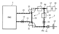
- FIG. 1 is a schematic view showing an overall configuration of an internal combustion engine according to an embodiment of the present invention.
- FIG. 2 is an explanatory diagram showing a state of the internal combustion engine according to the same embodiment when the engine is stopped after the fuel is cut.
- FIG. 3 is an explanatory diagram showing the operation of the internal combustion engine according to the same embodiment at the time of fuel cut recovery (during cranking).
- FIG. 4 is an explanatory diagram showing the operation of the internal combustion engine according to the same embodiment at the time of fuel cut recovery (after the engine speed has increased).
- FIG. 5 is an explanatory diagram showing the operation of the internal combustion engine according to the same embodiment at the time of fuel cut recovery (after the lapse of the intake delay period).
- FIG. 6 is a flowchart showing the content of control of the internal combustion engine according to the same embodiment at the time of fuel cut.
- FIG. 7 is a flowchart showing the content of control of the internal combustion engine according to the same embodiment at the time of fuel cut recovery.
- FIG. 8 is an explanatory diagram showing the content of the intake delay time lapse determination process of the control at the time of fuel cut recovery.
- FIG. 9 is an explanatory diagram of the operation of the internal combustion engine from the time when the engine is stopped due to the fuel cut to the time when the engine is restarted by the fuel cut recoverer by a time chart.
- FIG. 1 shows the overall configuration of an internal combustion engine 1 according to an embodiment of the present invention.
- the internal combustion engine 1 (hereinafter referred to as “internal combustion engine”, sometimes simply referred to as “engine”) 1 constitutes a drive source that is mounted on a vehicle and forms a driving force of the vehicle.
- the internal combustion engine 1 can be configured as a single drive source for a vehicle, or can be configured in cooperation with an electric motor or a motor generator.
- the drive source in the latter case may be of either a series type or a parallel type.
- the internal combustion engine 1 includes a turbocharger 2.
- the supercharger 2 includes an intake compressor 21 and an exhaust turbine 22, and the intake compressor 21 is interposed in the intake passage 11 of the internal combustion engine 1, and the exhaust turbine 22 is interposed in the exhaust passage 15.
- the intake compressor 21 and the exhaust turbine 22 are coupled by a shaft 23, and the rotation of the exhaust turbine 22 is transmitted to the intake compressor 21 via the shaft 23 to rotate the intake compressor 21.
- an air cleaner 12 is installed on the upstream side of the intake compressor 21 with respect to the flow of intake air, a throttle valve 13 is installed on the downstream side, and a fuel injection valve 14 is installed on the downstream side thereof. ..
- the air cleaner 12 removes foreign matter contained in the air sucked into the intake passage 11 from the atmosphere, and the throttle valve 13 expands the substantial cross-sectional area of the intake passage 11 (hereinafter, may be referred to as "effective cross-sectional area"). Or reduce it to adjust the amount of air sucked into the cylinder.
- the fuel injection valve 14 is arranged in the cylinder so as to be able to supply fuel. In the present embodiment, the fuel injection valve 14 is embedded in the cylinder head and injects fuel toward the intake port.
- the catalytic converters 16 and 17 are installed on the downstream side of the exhaust turbine 22 with respect to the flow of exhaust gas, and the muffler 18 is installed further on the downstream side thereof.
- the catalysts contained in the catalytic converters 16 and 17 may be of different types or have the same capacity. It may be.
- a three-way catalyst can be exemplified as the type of catalyst, but other catalysts having oxygen storage capacity can also be adopted.
- the number of catalytic converters may be only one (for example, the catalytic converter 16), or may be three or more.
- the internal combustion engine 1 further includes an EGR system 3 that recirculates the exhaust gas after combustion as EGR gas into the cylinder.
- the EGR system 3 includes an EGR passage 31 connected between the intake passage 11 and the exhaust passage 15, and the intake passage 11 and the exhaust passage 15 are connected to each other by the EGR passage 31 so that fluid can communicate with each other.
- the EGR passage 31 is the portion of the exhaust passage 15 downstream of the exhaust turbine 22, specifically, the portion between the two catalytic converters 16 and 17, (branch point Pd), and the intake passage 11. Of these, it is connected between the portion on the upstream side (connection point Pm) of the intake compressor 21.
- an EGR cooler 32 and an EGR valve 33 are installed as elements other than the EGR passage 31 constituting the EGR system.
- the EGR cooler 32 cools the exhaust gas branched from the exhaust passage 15, and the EGR valve 33 expands or contracts the substantial cross-sectional area (effective cross-sectional area) of the EGR passage 31 and returns the exhaust gas (effective cross-sectional area) to the inside of the cylinder. Adjust the amount of EGR gas).
- the internal combustion engine 1 includes an intake shutter valve 41 installed in the intake passage 11 on the upstream side of the connection point Pm of the EGR passage 31 with respect to the intake flow.
- the intake shutter valve 41 is configured so that the effective cross-sectional area of the intake passage 11 can be adjusted.
- the pressure on the downstream side of the intake passage 11 is reduced by reducing the effective cross-sectional area of the intake passage 11, and the EGR passage is reduced.
- It is configured as an admission valve (hereinafter unified by the name of "admission valve") that increases the differential pressure between the inlet side (branch point Pd) and the outlet side (connection point Pm) of 31.
- the "intake shutter valve” is configured as an admission valve 41 so that the opening degree can be adjusted stepwise or continuously, but it is adjusted only to two positions, the maximum opening degree and the minimum opening degree. It may be possible. As such a case, a case where the expansion of the differential pressure is not required for the operation of the EGR system can be exemplified. Then, for example, the maximum opening degree is the opening degree when fully opened (fully opened opening degree), and the minimum opening degree is the opening degree when fully closed (fully closed opening degree).
- the EGR valve 33 is not only configured so that the opening degree can be adjusted stepwise or continuously, but is also configured so that the opening degree can be switched only between the maximum opening degree and the minimum opening degree. Is possible.
- the engine controller 101 is configured as an electronic control unit, and includes a central processing unit (CPU), various storage devices such as RAM and ROM, and a microcomputer provided with an input / output interface and the like.
- CPU central processing unit
- RAM random access memory
- ROM read-only memory
- microcomputer provided with an input / output interface and the like.
- the engine controller 101 inputs detection signals of various operating state sensors that detect the operating state of the internal combustion engine 1, executes a predetermined calculation based on the detected operating state, and determines the fuel injection amount of the internal combustion engine 1. Set the fuel injection timing, ignition timing, etc.
- the accelerator sensor 111 that detects the amount of operation of the accelerator pedal by the driver (hereinafter referred to as “accelerator opening”) APO, the rotation speed sensor 112 that detects the rotation speed NE of the internal combustion engine 1,
- a cooling water temperature sensor 113 or the like for detecting the temperature TW of the engine cooling water is provided, and an air flow meter, a throttle sensor, an air fuel ratio sensor and the like (not shown) are provided.
- the elimination of the oxygen storage state is generally performed by, for example, operating the fuel injection valve 14 (rich spike operation) that temporarily increases the air-fuel ratio of the exhaust gas from the theoretical value.
- the EGR gas is circulated between the inside of the cylinder and the EGR passage 31 while the admission valve 41 is kept closed after the start of cranking, and the cylinder is used. Suppress the introduction of air into the interior. Then, when the engine speed has risen sufficiently and the predetermined speed at which combustion can be restarted is reached, the admission valve 41 is opened and the introduction of air is started. Further, after the start of air introduction, the execution of the fuel cut recovery is suspended until the introduced air reaches the intake port and the EGR gas in the intake passage 11 downstream of the admission valve 41 is replaced with air, and the EGR is held. After the replacement of gas with air is completed, this is executed to restart the supply of fuel to the internal combustion engine 1 and restart combustion.
- FIGS. 2 to 5 show in chronological order the operation of the internal combustion engine 1 according to the present embodiment from the time of stopping due to the fuel cut to the time of restarting by the fuel cut recovery cover.
- the thick dotted line conceptually shows the behavior of the exhaust gas or the EGR gas
- the direction of the arrow indicates the presence or absence of the flow and its direction.
- FIG. 9 shows the operation of the internal combustion engine 1 from before the fuel cut to after the fuel cut recovery by a time chart.
- the time Toff indicates the time when the accelerator is off
- the time Treq indicates the time when the fuel cut condition is satisfied
- the time Tcut indicates the time when the fuel cut is executed.
- time Trcv indicates the time when the fuel cut recovery condition is satisfied
- time Trst indicates the time when the fuel cut recovery is executed.
- the case of so-called deceleration fuel cut in which the fuel is cut when the vehicle is decelerated, is described on the premise that the internal combustion engine 1 alone constitutes the drive source of the vehicle.
- the fuel cut (and the subsequent fuel cut recovery cover) will be described. ) Is not limited to this, and the vehicle may be temporarily stopped, for example, while waiting for a traffic light.
- the deceleration fuel cut may be performed during so-called coastal operation from deceleration to stopping.
- the "fuel cut” means a general operation of temporarily stopping the supply of fuel to the internal combustion engine 1 (in other words, during the operation of the engine controller 101), and the vehicle is stopped. It shall also include the case of so-called idle stop.
- the internal combustion engine 1 forms a drive source in cooperation with an electric motor, it may include a case of switching to a mode in which the internal combustion engine 1 travels only by the electric motor.
- FIG. 2 shows the state when the engine is stopped after the fuel is cut (time Tstp in FIG. 9). Due to the gas replacement performed when the fuel is cut, in addition to the exhaust passage 15 and the EGR passage 31, the intake passage 11 downstream of the admission valve 41 is also filled with EGR gas.
- the admission valve 41 is continuously closed from the time of fuel cut, and the EGR valve 33 is in the opened state. In the present embodiment, the admission valve 41 is fully closed and the EGR valve 33 is fully opened. By closing the admission valve 41, the introduction of air downstream thereof is suppressed.
- FIG. 3 shows the state during cranking after the fuel cut recovery condition is satisfied (time Trcv to Trev).
- the admission valve 41 is in the fully closed position, while the EGR valve 33 is in the fully open position, which promotes the introduction of EGR gas from the exhaust passage 15 to the intake passage 11 via the EGR passage 31, and promotes the introduction of EGR gas into the cylinder and in the EGR.
- EGR gas circulates with the passage 31.
- the throttle valve 13 is adjusted to maintain a fully closed state when the power of the engine controller 101 is turned off. However, in the present embodiment, the throttle valve 13 is controlled to a fully open position by turning on the power, and remains in the fully open position while cranking is continued. Be retained.
- the EGR valve 33 By closing the EGR gas, the EGR gas may not be circulated.
- FIG. 4 shows the state after the engine speed has sufficiently increased due to cranking (time Trev to Trst).
- the admission valve 41 is opened in order to replace the EGR gas filled in the intake passage 11 with air in preparation for the resumption of combustion.
- the EGR valve 33 is closed to prevent the introduction of new EGR gas into the intake passage 11.
- the admission valve 41 is fully opened while the EGR valve 33 is fully closed.
- the EGR gas that was in the intake passage 11 when the fuel cut recovery condition is satisfied is sent out to the exhaust passage 15 by air, and air is introduced into the cylinder.
- the air reaches the intake port, it can be considered that the replacement with air is completed.
- a thick dotted line with an arrow indicates the behavior of EGR gas
- a two-dot chain line with an arrow indicates the behavior of air.
- FIG. 5 shows the state at the time of execution of the fuel cut recovery (time Trst). After the admission valve 41 is opened, the fuel supply to the internal combustion engine 1 is restarted when the air passes through the admission valve 41 and reaches the intake port, in other words, when the intake delay period ⁇ Tdry elapses. And restart the combustion.
- FIG. 6 and 7 show the operation of the engine controller 101 by a flowchart
- FIG. 6 shows the operation related to the fuel cut control
- FIG. 7 shows the operation related to the fuel cut recovery control, respectively.
- the engine controller 101 is programmed to execute the fuel cut control when the predetermined fuel cut condition is satisfied, and to execute the fuel cut recovery control when the predetermined fuel cut recovery condition is satisfied after the execution of the fuel cut. ing.
- the fuel cut condition is that the rotation speed of the internal combustion engine 1 at the time when the accelerator off state continues for a predetermined time or longer is equal to or higher than the predetermined rotation speed, and the brake is applied by the driver. In addition, it is judged that it has been established. If the fuel cut condition is satisfied, the process proceeds to S103, and if not, the processes of S101 and 102 are repeated.
- the fuel may be cut and the internal combustion engine 1 may be automatically stopped.
- the success or failure of the automatic stop condition of the internal combustion engine 1 is determined as the fuel cut condition based on the battery charge state and the accelerator opening. It is possible.
- the admission valve 41 is closed (specifically, fully closed).
- the EGR valve 33 is opened (specifically, fully opened). This promotes the circulation of EGR gas between the inside of the cylinder and the EGR passage 31.
- the transportation delay time refers to the time corresponding to the transportation delay of the EGR gas from the connection point Pm of the EGR passage 31 to the intake port after the admission valve 41 is closed, and whether or not this has elapsed is the internal combustion engine. It is possible to estimate based on the operating state of the engine 1. Similar to the estimation of the intake delay period ⁇ Tdry described later, the flow rate of EGR gas passing through the intake valve (intake valve passing flow rate) is integrated per unit time to calculate the volume passing through the intake valve (intake valve passing volume). Then, when this reaches a predetermined volume corresponding to the volume of the intake passage 11, it is estimated that the transport delay time has elapsed. If the transportation delay time has elapsed, the process proceeds to S107, and if not, the process proceeds to S106.
- S106 it is determined whether or not the fuel cut cancellation condition is satisfied.
- the fuel cut cancellation condition is satisfied, for example, when the accelerator pedal is depressed while waiting for the elapse of the transportation delay time to continue the fuel supply. If the fuel cut cancellation condition is satisfied, the process proceeds to S108, and if the fuel cut cancellation condition is not satisfied, the process returns to S105 and continues to wait for the elapse of the transportation delay time.
- fuel cut is executed. Specifically, the operation of the fuel injection valve 14 is stopped, and the supply of fuel to the internal combustion engine 1 is stopped. Along with this, the operation of the spark plug (not shown) is also stopped.
- S201 it is determined whether or not the fuel cut recovery condition is satisfied. In the present embodiment, it is determined that the fuel cut recovery condition is satisfied when the brake operated by the driver is released by the brake pedal being completely returned or returned to a state close to this. To. If the fuel cut recovery condition is satisfied, the process proceeds to S202, and if not, the process of S201 is repeated.
- the fuel cut recovery condition (that is, the internal combustion engine 1) It is possible to determine that the restart condition) has been met.
- the admission valve 41 is closed (specifically, fully closed). In the present embodiment, since the admission valve 41 is already closed at the time of fuel cut, the closed state is continued.
- the EGR valve 33 is opened (specifically, fully opened). Similar to the admission valve 41, the state at the time of fuel cut (valve open state) is continued.
- cranking of the internal combustion engine 1 is started. Cranking (sometimes called “motoring") is done by an electric motor such as an ISG (Integrated Starter Generator).
- ISG Integrated Starter Generator
- the internal combustion engine 1 cooperates with an electric motor or a motor generator to form a drive source, it is possible to perform cranking by these rotating electric machines.
- the admission valve 41 is in the closed state and the EGR valve 33 is in the open state, the exhaust gas in the exhaust passage 15 during cranking is directed toward the branch point Pd downstream of the exhaust passage 15. Is guided to the intake passage 11 via the EGR passage 31 without passing through.
- the admission valve 41 is opened (for example, fully opened). As a result, air is allowed to pass through the admission valve 41 and the connection point Pm and be introduced into the cylinder.
- the EGR valve 33 is closed (for example, fully closed). As a result, the introduction of the EGR gas into the intake passage 11 is prevented, and as the introduction of air through the admission valve 41 progresses, the gas occupying the intake passage 11 is replaced with air from the EGR gas.
- the intake delay time ⁇ Tdry is the time corresponding to the delay in transporting the air that has passed through the admission valve 41 to the intake port via the connection point Pm after the admission valve 41 is opened. It is possible to determine whether or not this has been done by estimation based on the operating state of the internal combustion engine 1. If the intake delay time ⁇ Tdry has elapsed, the process proceeds to S209, and if not, the determination of S208 is repeated and the elapse is awaited.
- FIG. 8 shows the principle of determining the progress in the case of estimation.
- the flow rate of air passing through the intake valve (flow rate passing through the intake valve) is given for each opening of the throttle valve 13 (hereinafter referred to as “throttle opening”) THO, and each throttle is opened. It is possible to predetermine the degree THO as a function with respect to the engine speed NE, for example, a monotonically increasing function. Then, the intake valve passing volume of air is calculated by integrating the intake valve passing flow rate, and when the intake valve passing volume reaches a predetermined volume Vthr corresponding to the volume of the intake passage 11 after the start of integration (time T0). It is determined that the intake delay time ⁇ Tdry has elapsed at (time T1).
- Whether or not the transportation delay time ⁇ Tdry has elapsed can be determined not only by such an estimation but also by actual measurement using a sensor.
- a gas state sensor for example, an oxygen concentration sensor
- the admission valve 41 is opened, and then the gas detected by the gas state sensor is used.
- the behavior indicating the arrival of air occurs in the state, it is determined that the intake delay time ⁇ Tdry has elapsed.
- the oxygen concentration rises above a predetermined concentration when the oxygen concentration sensor is used.
- the air transport delay is "the delay required to replace the EGR gas with air in the intake passage downstream of the intake shutter valve” or "the air occupied in the cylinder after opening the intake shutter valve ( It can be rephrased as "the delay until the ratio of oxygen) rises and reaches a predetermined value.”
- the engine controller 101 constitutes an "internal combustion engine control device".
- the internal combustion engine 1 and its control device according to the present embodiment have the above configurations, and the effects obtained by the present embodiment will be described below.
- the air oxygen
- the admission valve 41 closed while continuing the cranking of the internal combustion engine 1. It is possible to prevent the air from flowing into the intake passage 11 downstream of the valve 41, passing through the cylinder unreacted, and flowing into the catalyst. As a result, it is possible to prevent the catalyst from forming an excessive oxidizing atmosphere and deteriorating the purification rate of NOx (nitrogen oxide).
- the EGR valve 33 is opened to expand the effective cross-sectional area of the EGR passage 31, so that the EGR gas is circulated between the cylinder and the EGR passage 31 while the cranking is continued. This makes it possible to reduce the load on the cranking motor and more reliably suppress the inflow of air into the catalyst.
- the admission valve 41 After opening the admission valve 41, by waiting for the elapse of the intake delay period ⁇ Tdry indicating the arrival of air to the intake port and restarting combustion, it is possible to set the intake delay period ⁇ Tdry without excess or deficiency. It is possible to prevent the exhaust from being deteriorated due to the delay in the resumption of combustion and the inflow of air into the catalyst, or the supply of fuel in a state where the resumption of combustion is early and the ignition is unstable.
- the catalyst converter 16 in the exhaust passage 15 on the upstream side of the branch point Pd of the EGR passage 31, the gas discharged from the cylinder passes through the catalyst before reaching the branch point Pd. It will be. According to the present embodiment, in such a situation, it is possible to suppress the inflow of air into the catalyst and surely suppress the deterioration of the exhaust gas.
- the EGR system 3 recirculates the exhaust gas flowing through the exhaust passage 15 downstream of the exhaust turbine 22 to the intake passage 11 upstream of the intake compressor 21 as EGR gas, so that the existing low-pressure EGR system 3 is provided.
- the valve device that is, the admission valve 41
- the control according to this embodiment is not limited to the so-called low pressure type EGR system, but can also be applied to the high pressure type EGR system.
- a catalyst is provided on the upstream side of the exhaust passage from the exhaust turbine, the exhaust passage on the downstream side of the catalyst and the intake passage on the downstream side of the throttle valve are connected by an EGR passage for combustion. By closing the throttle valve when restarting after cutting, the introduction of air into the intake passage is suppressed.
- the exhaust passage on the downstream side of the catalyst and the intake passage on the downstream side of the throttle valve are connected by an EGR passage, and the throttle valve functions as an "intake shutter valve".
- the throttle valve functions as an "intake shutter valve”.
Landscapes
- Engineering & Computer Science (AREA)
- Chemical & Material Sciences (AREA)
- Combustion & Propulsion (AREA)
- Mechanical Engineering (AREA)
- General Engineering & Computer Science (AREA)
- Exhaust-Gas Circulating Devices (AREA)
- Output Control And Ontrol Of Special Type Engine (AREA)
- Control Of Vehicle Engines Or Engines For Specific Uses (AREA)
Priority Applications (2)
| Application Number | Priority Date | Filing Date | Title |
|---|---|---|---|
| PCT/IB2019/000645 WO2021001669A1 (ja) | 2019-07-04 | 2019-07-04 | 内燃エンジンの制御方法および制御装置 |
| JP2021529535A JP7287464B2 (ja) | 2019-07-04 | 2019-07-04 | 内燃エンジンの制御方法および制御装置 |
Applications Claiming Priority (1)
| Application Number | Priority Date | Filing Date | Title |
|---|---|---|---|
| PCT/IB2019/000645 WO2021001669A1 (ja) | 2019-07-04 | 2019-07-04 | 内燃エンジンの制御方法および制御装置 |
Publications (1)
| Publication Number | Publication Date |
|---|---|
| WO2021001669A1 true WO2021001669A1 (ja) | 2021-01-07 |
Family
ID=74101158
Family Applications (1)
| Application Number | Title | Priority Date | Filing Date |
|---|---|---|---|
| PCT/IB2019/000645 Ceased WO2021001669A1 (ja) | 2019-07-04 | 2019-07-04 | 内燃エンジンの制御方法および制御装置 |
Country Status (2)
| Country | Link |
|---|---|
| JP (1) | JP7287464B2 (https=) |
| WO (1) | WO2021001669A1 (https=) |
Cited By (3)
| Publication number | Priority date | Publication date | Assignee | Title |
|---|---|---|---|---|
| WO2022176173A1 (ja) * | 2021-02-19 | 2022-08-25 | 日産自動車株式会社 | シリーズハイブリッド車両の制御方法及びシリーズハイブリッド車両の制御装置 |
| JP7613237B2 (ja) | 2021-04-23 | 2025-01-15 | マツダ株式会社 | エンジンの制御装置 |
| WO2025154203A1 (ja) * | 2024-01-17 | 2025-07-24 | 日産自動車株式会社 | 内燃機関の負圧生成バルブ制御方法および装置 |
Citations (5)
| Publication number | Priority date | Publication date | Assignee | Title |
|---|---|---|---|---|
| JP2008215257A (ja) * | 2007-03-06 | 2008-09-18 | Toyota Motor Corp | 内燃機関の始動装置 |
| JP2010281286A (ja) * | 2009-06-05 | 2010-12-16 | Toyota Motor Corp | 内燃機関の始動制御装置 |
| JP2011247166A (ja) * | 2010-05-26 | 2011-12-08 | Denso Corp | エンジン制御装置 |
| JP2016089784A (ja) * | 2014-11-10 | 2016-05-23 | 日産自動車株式会社 | エンジンのegr制御装置 |
| JP2019027296A (ja) * | 2017-07-26 | 2019-02-21 | 愛三工業株式会社 | エンジンシステム |
-
2019
- 2019-07-04 JP JP2021529535A patent/JP7287464B2/ja active Active
- 2019-07-04 WO PCT/IB2019/000645 patent/WO2021001669A1/ja not_active Ceased
Patent Citations (5)
| Publication number | Priority date | Publication date | Assignee | Title |
|---|---|---|---|---|
| JP2008215257A (ja) * | 2007-03-06 | 2008-09-18 | Toyota Motor Corp | 内燃機関の始動装置 |
| JP2010281286A (ja) * | 2009-06-05 | 2010-12-16 | Toyota Motor Corp | 内燃機関の始動制御装置 |
| JP2011247166A (ja) * | 2010-05-26 | 2011-12-08 | Denso Corp | エンジン制御装置 |
| JP2016089784A (ja) * | 2014-11-10 | 2016-05-23 | 日産自動車株式会社 | エンジンのegr制御装置 |
| JP2019027296A (ja) * | 2017-07-26 | 2019-02-21 | 愛三工業株式会社 | エンジンシステム |
Cited By (7)
| Publication number | Priority date | Publication date | Assignee | Title |
|---|---|---|---|---|
| WO2022176173A1 (ja) * | 2021-02-19 | 2022-08-25 | 日産自動車株式会社 | シリーズハイブリッド車両の制御方法及びシリーズハイブリッド車両の制御装置 |
| JPWO2022176173A1 (https=) * | 2021-02-19 | 2022-08-25 | ||
| CN116888024A (zh) * | 2021-02-19 | 2023-10-13 | 日产自动车株式会社 | 串联式混合动力车辆的控制方法及控制装置 |
| JP7521678B2 (ja) | 2021-02-19 | 2024-07-24 | 日産自動車株式会社 | シリーズハイブリッド車両の制御方法及びシリーズハイブリッド車両の制御装置 |
| US12077149B2 (en) | 2021-02-19 | 2024-09-03 | Nissan Motor Co., Ltd. | Control method for series hybrid vehicle and control device for series hybrid vehicle |
| JP7613237B2 (ja) | 2021-04-23 | 2025-01-15 | マツダ株式会社 | エンジンの制御装置 |
| WO2025154203A1 (ja) * | 2024-01-17 | 2025-07-24 | 日産自動車株式会社 | 内燃機関の負圧生成バルブ制御方法および装置 |
Also Published As
| Publication number | Publication date |
|---|---|
| JPWO2021001669A1 (https=) | 2021-01-07 |
| JP7287464B2 (ja) | 2023-06-06 |
Similar Documents
| Publication | Publication Date | Title |
|---|---|---|
| US8914172B2 (en) | Control method and device for hybrid motor | |
| US8438841B2 (en) | Particulate filter regeneration in an engine | |
| US8424295B2 (en) | Particulate filter regeneration during engine shutdown | |
| US8402751B2 (en) | Particulate filter regeneration in an engine | |
| US8516797B2 (en) | Control of exhaust flow in an engine including a particulate filter | |
| JP4453602B2 (ja) | 内燃機関の排気浄化システム | |
| US8438840B2 (en) | Particulate filter regeneration in an engine | |
| JP4858278B2 (ja) | 内燃機関の排気再循環装置 | |
| US20100126142A1 (en) | Internal combustion engine exhaust gas control system and control method of internal combustion engine exhaust gas control system | |
| US20130118154A1 (en) | Controlling operation of exhaust of an engine including a particulate filter | |
| JP2010038147A (ja) | エンジンの排気浄化システム | |
| JP2002213231A (ja) | 内燃機関の排気浄化装置 | |
| JP2014114754A (ja) | 内燃機関の制御装置 | |
| JP7287464B2 (ja) | 内燃エンジンの制御方法および制御装置 | |
| US8402753B2 (en) | Exhaust gas purification system for an internal combustion engine | |
| US8843259B2 (en) | Control apparatus for hybrid vehicle | |
| JP2008151064A (ja) | 内燃機関の制御装置 | |
| JP6946871B2 (ja) | 内燃機関の制御システム | |
| JP3558019B2 (ja) | 還元剤供給装置の異常検出装置 | |
| JP7287465B2 (ja) | 内燃エンジンの制御方法および制御装置 | |
| JP2008106725A (ja) | 内燃機関の排気システム | |
| JP2013160156A (ja) | 内燃機関の故障判定装置および車両 | |
| JP4123707B2 (ja) | エンジンの制御装置 | |
| JP2005330886A (ja) | エンジンのアイドル停止制御装置 | |
| JP6154315B2 (ja) | エンジンの排気還流装置 |
Legal Events
| Date | Code | Title | Description |
|---|---|---|---|
| 121 | Ep: the epo has been informed by wipo that ep was designated in this application |
Ref document number: 19934373 Country of ref document: EP Kind code of ref document: A1 |
|
| ENP | Entry into the national phase |
Ref document number: 2021529535 Country of ref document: JP Kind code of ref document: A |
|
| NENP | Non-entry into the national phase |
Ref country code: DE |
|
| 122 | Ep: pct application non-entry in european phase |
Ref document number: 19934373 Country of ref document: EP Kind code of ref document: A1 |