WO2020262308A1 - 流路構造、これを備えた逆止弁、及び逆止弁の製造方法 - Google Patents
流路構造、これを備えた逆止弁、及び逆止弁の製造方法 Download PDFInfo
- Publication number
- WO2020262308A1 WO2020262308A1 PCT/JP2020/024428 JP2020024428W WO2020262308A1 WO 2020262308 A1 WO2020262308 A1 WO 2020262308A1 JP 2020024428 W JP2020024428 W JP 2020024428W WO 2020262308 A1 WO2020262308 A1 WO 2020262308A1
- Authority
- WO
- WIPO (PCT)
- Prior art keywords
- retaining ring
- check valve
- flow path
- path structure
- diameter
- Prior art date
- Legal status (The legal status is an assumption and is not a legal conclusion. Google has not performed a legal analysis and makes no representation as to the accuracy of the status listed.)
- Ceased
Links
Images








Classifications
-
- B—PERFORMING OPERATIONS; TRANSPORTING
- B23—MACHINE TOOLS; METAL-WORKING NOT OTHERWISE PROVIDED FOR
- B23P—METAL-WORKING NOT OTHERWISE PROVIDED FOR; COMBINED OPERATIONS; UNIVERSAL MACHINE TOOLS
- B23P15/00—Making specific metal objects by operations not covered by a single other subclass or a group in this subclass
- B23P15/001—Making specific metal objects by operations not covered by a single other subclass or a group in this subclass valves or valve housings
-
- F—MECHANICAL ENGINEERING; LIGHTING; HEATING; WEAPONS; BLASTING
- F16—ENGINEERING ELEMENTS AND UNITS; GENERAL MEASURES FOR PRODUCING AND MAINTAINING EFFECTIVE FUNCTIONING OF MACHINES OR INSTALLATIONS; THERMAL INSULATION IN GENERAL
- F16K—VALVES; TAPS; COCKS; ACTUATING-FLOATS; DEVICES FOR VENTING OR AERATING
- F16K15/00—Check valves
- F16K15/02—Check valves with guided rigid valve members
-
- B—PERFORMING OPERATIONS; TRANSPORTING
- B21—MECHANICAL METAL-WORKING WITHOUT ESSENTIALLY REMOVING MATERIAL; PUNCHING METAL
- B21F—WORKING OR PROCESSING OF METAL WIRE
- B21F11/00—Cutting wire
-
- B—PERFORMING OPERATIONS; TRANSPORTING
- B21—MECHANICAL METAL-WORKING WITHOUT ESSENTIALLY REMOVING MATERIAL; PUNCHING METAL
- B21F—WORKING OR PROCESSING OF METAL WIRE
- B21F3/00—Coiling wire into particular forms
- B21F3/02—Coiling wire into particular forms helically
- B21F3/06—Coiling wire into particular forms helically internally on a hollow form
-
- B—PERFORMING OPERATIONS; TRANSPORTING
- B21—MECHANICAL METAL-WORKING WITHOUT ESSENTIALLY REMOVING MATERIAL; PUNCHING METAL
- B21F—WORKING OR PROCESSING OF METAL WIRE
- B21F37/00—Manufacture of rings from wire
- B21F37/02—Manufacture of rings from wire of resilient rings, e.g. key-rings
-
- B—PERFORMING OPERATIONS; TRANSPORTING
- B23—MACHINE TOOLS; METAL-WORKING NOT OTHERWISE PROVIDED FOR
- B23P—METAL-WORKING NOT OTHERWISE PROVIDED FOR; COMBINED OPERATIONS; UNIVERSAL MACHINE TOOLS
- B23P19/00—Machines for simply fitting together or separating metal parts or objects, or metal and non-metal parts, whether or not involving some deformation; Tools or devices therefor so far as not provided for in other classes
- B23P19/02—Machines for simply fitting together or separating metal parts or objects, or metal and non-metal parts, whether or not involving some deformation; Tools or devices therefor so far as not provided for in other classes for connecting objects by press fit or for detaching same
-
- F—MECHANICAL ENGINEERING; LIGHTING; HEATING; WEAPONS; BLASTING
- F16—ENGINEERING ELEMENTS AND UNITS; GENERAL MEASURES FOR PRODUCING AND MAINTAINING EFFECTIVE FUNCTIONING OF MACHINES OR INSTALLATIONS; THERMAL INSULATION IN GENERAL
- F16K—VALVES; TAPS; COCKS; ACTUATING-FLOATS; DEVICES FOR VENTING OR AERATING
- F16K1/00—Lift valves or globe valves, i.e. cut-off apparatus with closure members having at least a component of their opening and closing motion perpendicular to the closing faces
- F16K1/32—Details
-
- F—MECHANICAL ENGINEERING; LIGHTING; HEATING; WEAPONS; BLASTING
- F16—ENGINEERING ELEMENTS AND UNITS; GENERAL MEASURES FOR PRODUCING AND MAINTAINING EFFECTIVE FUNCTIONING OF MACHINES OR INSTALLATIONS; THERMAL INSULATION IN GENERAL
- F16K—VALVES; TAPS; COCKS; ACTUATING-FLOATS; DEVICES FOR VENTING OR AERATING
- F16K15/00—Check valves
- F16K15/02—Check valves with guided rigid valve members
- F16K15/025—Check valves with guided rigid valve members the valve being loaded by a spring
- F16K15/026—Check valves with guided rigid valve members the valve being loaded by a spring the valve member being a movable body around which the medium flows when the valve is open
-
- F—MECHANICAL ENGINEERING; LIGHTING; HEATING; WEAPONS; BLASTING
- F16—ENGINEERING ELEMENTS AND UNITS; GENERAL MEASURES FOR PRODUCING AND MAINTAINING EFFECTIVE FUNCTIONING OF MACHINES OR INSTALLATIONS; THERMAL INSULATION IN GENERAL
- F16K—VALVES; TAPS; COCKS; ACTUATING-FLOATS; DEVICES FOR VENTING OR AERATING
- F16K15/00—Check valves
- F16K15/02—Check valves with guided rigid valve members
- F16K15/06—Check valves with guided rigid valve members with guided stems
- F16K15/063—Check valves with guided rigid valve members with guided stems the valve being loaded by a spring
-
- F—MECHANICAL ENGINEERING; LIGHTING; HEATING; WEAPONS; BLASTING
- F16—ENGINEERING ELEMENTS AND UNITS; GENERAL MEASURES FOR PRODUCING AND MAINTAINING EFFECTIVE FUNCTIONING OF MACHINES OR INSTALLATIONS; THERMAL INSULATION IN GENERAL
- F16K—VALVES; TAPS; COCKS; ACTUATING-FLOATS; DEVICES FOR VENTING OR AERATING
- F16K15/00—Check valves
- F16K15/02—Check valves with guided rigid valve members
- F16K15/06—Check valves with guided rigid valve members with guided stems
- F16K15/067—Check valves with guided rigid valve members with guided stems stem guided at two or more points
-
- F—MECHANICAL ENGINEERING; LIGHTING; HEATING; WEAPONS; BLASTING
- F16—ENGINEERING ELEMENTS AND UNITS; GENERAL MEASURES FOR PRODUCING AND MAINTAINING EFFECTIVE FUNCTIONING OF MACHINES OR INSTALLATIONS; THERMAL INSULATION IN GENERAL
- F16K—VALVES; TAPS; COCKS; ACTUATING-FLOATS; DEVICES FOR VENTING OR AERATING
- F16K27/00—Construction of housing; Use of materials therefor
- F16K27/02—Construction of housing; Use of materials therefor of lift valves
- F16K27/0209—Check valves or pivoted valves
-
- F—MECHANICAL ENGINEERING; LIGHTING; HEATING; WEAPONS; BLASTING
- F16—ENGINEERING ELEMENTS AND UNITS; GENERAL MEASURES FOR PRODUCING AND MAINTAINING EFFECTIVE FUNCTIONING OF MACHINES OR INSTALLATIONS; THERMAL INSULATION IN GENERAL
- F16B—DEVICES FOR FASTENING OR SECURING CONSTRUCTIONAL ELEMENTS OR MACHINE PARTS TOGETHER, e.g. NAILS, BOLTS, CIRCLIPS, CLAMPS, CLIPS OR WEDGES; JOINTS OR JOINTING
- F16B21/00—Means for preventing relative axial movement of a pin, spigot, shaft or the like and a member surrounding it; Stud-and-socket releasable fastenings
- F16B21/10—Means for preventing relative axial movement of a pin, spigot, shaft or the like and a member surrounding it; Stud-and-socket releasable fastenings by separate parts
- F16B21/16—Means for preventing relative axial movement of a pin, spigot, shaft or the like and a member surrounding it; Stud-and-socket releasable fastenings by separate parts with grooves or notches in the pin or shaft
- F16B21/18—Means for preventing relative axial movement of a pin, spigot, shaft or the like and a member surrounding it; Stud-and-socket releasable fastenings by separate parts with grooves or notches in the pin or shaft with circlips or like resilient retaining devices, i.e. resilient in the plane of the ring or the like; Details
- F16B21/183—Means for preventing relative axial movement of a pin, spigot, shaft or the like and a member surrounding it; Stud-and-socket releasable fastenings by separate parts with grooves or notches in the pin or shaft with circlips or like resilient retaining devices, i.e. resilient in the plane of the ring or the like; Details internal, i.e. with spreading action
Definitions
- the present invention relates to a flow path structure, a check valve provided with the flow path structure, and a method for manufacturing the check valve.
- a check valve has been used to control the flow direction of the refrigerant (fluid) in the refrigeration cycle used for air conditioning equipment such as car air conditioners.
- Patent Document 1 is a three-way opening including a valve body including a first inlet and a second inlet arranged on a common axis, a cylinder portion connecting them, and an outlet orthogonal to the cylinder portion.
- the check valve is disclosed.
- the three-way check valve of Patent Document 1 includes a valve body slidable in the cylinder and a stopper provided near the second inlet and having an orifice. Therefore, when the supply of the fluid from the second inlet side is cut off and the supply is switched to the supply from the first inlet side, the valve body slides in the cylinder portion and hits the stopper due to the inflowing pressure, and tapers. The part functions to seal the orifice.
- the stopper of Patent Document 1 is attached to the valve body by a snap ring fitted in a fitting groove formed near the second inlet.
- a general snap ring is provided with holes at both ends of a C-shaped plate material into which a tool such as snap ring pliers can be inserted for easy mounting. Therefore, both ends of the snap ring have a shape protruding toward the inner diameter side, but when the snap ring is attached to the fitting groove, both ends often protrude into the flow path.
- the present invention has been made in view of the above problems, and provides a flow path structure capable of ensuring a smooth fluid flow while reducing costs, a check valve provided with the flow path structure, and a method for manufacturing the check valve.
- the purpose is to do.
- the flow path structure according to the present invention is a flow path structure having a hollow main body and a retaining ring obtained by processing a linear steel material into a C shape, and the retaining ring is fitted inside the main body.
- An annular fitting groove is provided, and a fluid flows inside the retaining ring fitted in the fitting groove. Since the flow path structure in the present invention cannot be directly specified by its structure or characteristics or is almost impractical, the manufacturing method is described in a part of the claims.
- a flow path structure capable of ensuring a smooth fluid flow
- a check valve provided with the flow path structure
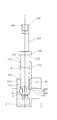
- FIG. 1 is an axial sectional view of the check valve of the present embodiment.
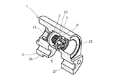
- FIG. 2 is an assembly perspective view of the check valve 1 shown in a state where the valve body is split in half along the axis.
- FIG. 3 is an exploded perspective view of the check valve 1 shown in a state where the valve body is divided in half along the axis.
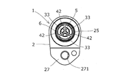
- FIG. 4 is a side view of the check valve from the direction of arrow A in FIG.
- FIG. 5 is a diagram showing a state in which the retaining ring is placed on a flat surface.
- FIG. 6 is a perspective view showing an example of a retaining ring manufacturing apparatus.
- FIG. 7 is a diagram showing an assembly process of the check valve.
- FIG. 8 is a diagram showing an assembly process of the check valve.
- FIG. 1 is an axial sectional view of the check valve of the present embodiment.
- FIG. 2 is an assembly perspective view of the check valve 1 shown in a state where the valve body is split in half along the axis.
- FIG. 9 is a diagram showing an assembly process of the check valve.
- FIG. 10 is a diagram showing an assembly process of the check valve.
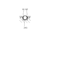
- FIG. 11 is a cross-sectional view passing through the axis of the check valve, in which the retaining ring and the retaining ring mounting groove are cut.
- FIG. 12 is an exploded view similar to FIG. 3 showing a check valve according to a comparative example.
- FIG. 13 is a view similar to FIG. 4 in which the check valve according to the comparative example is viewed from the side.
- the "C-shape” means that the number of turns of the spiral shape is more than 0.5 and less than 1, or the angle formed by two straight lines connecting the center and both ends of the shape is more than 180 degrees and less than 360 degrees.
- the shape that is. When a C-shaped member is placed on a flat surface and both ends are offset in the height direction, it is regarded as a part of the spiral shape.
- the “linear steel material” include, but are not limited to, hard steel wire, piano wire, and stainless steel wire.
- FIG. 1 is an axial sectional view of the check valve 1 of the present embodiment.
- FIG. 2 is an assembly perspective view of the check valve 1 shown in a state where the valve body 2 is split in half along the axis.
- FIG. 3 is an exploded perspective view of the check valve 1 shown in a state where the valve body 2 is divided in half along the axis.
- FIG. 4 is a side view of the check valve 1 from the direction of arrow A in FIG.
- L be the axis of the fluid passage of the check valve 1.
- the check valve 1 includes a hollow valve body (also referred to as a main body) 2 having a refrigerant flow path (also referred to as a fluid passage) through which a refrigerant passes, and a valve body 3 arranged in the fluid passage of the valve main body 2. It has a washer 4 attached to the valve body 2, a coil spring 5 that urges the valve body 3 against the washer 4, and a retaining ring 6 that fixes the washer 4 to the valve body 2.
- the check valve 1 is connected to a joint to which, for example, a refrigerant pipe connected to an evaporator and a compressor (not shown) is connected, whereby a closed refrigeration cycle is formed.
- a refrigerant pipe connected to an evaporator and a compressor (not shown) is connected, whereby a closed refrigeration cycle is formed.
- the left side of the check valve 1 is the inlet side of the refrigerant and the right side is the outlet side of the refrigerant.
- the valve body 2 provided with the flow path structure has a substantially cylindrical first connecting portion 21, a first intermediate passage 22, a central passage 23, and a substantially cylindrical shape from the inlet side of FIG. 1 along the axis L. It has a second intermediate passage 24 having a shape and a second connecting portion (large diameter cylindrical portion) 25 having a substantially cylindrical shape. Piping (not shown) can be connected to the first connecting portion 21 and the second connecting portion 25, respectively.
- the first intermediate passage 22 connecting the first connecting portion 21 and the central passage 23 has a tapered tubular portion 221 and a guide tubular portion 222 having a diameter smaller than that of the first connecting portion 21 toward the central passage 23 side.
- a valve seat 223 whose diameter is expanded in a tapered shape is connected in series.
- the second intermediate passage 24 connecting the central passage 23 and the second connecting portion 25 includes the first connecting cylinder portion 241 and the annular washer mounting portion 242, and the annular retaining ring mounting groove (fitting).
- the groove) 243 and the second connecting cylinder portion 244 are connected in series.
- the inner diameter of the washer mounting portion 242 is larger than the inner diameter of the first connecting cylinder portion 241, and the inner diameter of the retaining ring mounting groove 243 is larger than the inner diameter of the washer mounting portion 242.
- the inner diameter of the second connecting cylinder portion 244 is smaller than the inner diameter of the retaining ring mounting groove 243 and larger than the inner diameter of the washer mounting portion 242.
- the inner diameter of the second connecting portion 25 is larger than the inner diameter of the retaining ring mounting groove 243 and the inner diameter of the second connecting cylinder portion 244.
- the magnitude relationship of the inner diameter of each part is not limited to the above-mentioned example.
- the second connecting portion 25 may be equal to or less than the inner diameter of the retaining ring mounting groove 243, and the inner diameter of the second connecting portion 25 may be the same as the inner diameter of the washer mounting portion 242.
- valve body 2 has a first arm portion 26 extending radially outside the first connecting portion 21 and a second arm extending radially outside the second connecting portion 25. It has a part 27.
- a screw hole 261 for screwing a bolt (not shown) for fixing a pipe connected to the first connecting portion 21 is formed in the first arm portion 26, and the second arm portion 27 is formed with a screw hole 261. Is formed with a screw hole 271 for screwing a bolt (not shown) for fixing a pipe connected to the second connecting portion 25.
- the valve body 3 includes a disk portion 31, three leg portions 32 extending from the disk portion 31 to the first connecting portion 21 side along the axis L (FIG. 1), and a disk.
- Three leg portions 33 extending along the axis L are continuously provided from the portion 31 to the second connecting portion 25 side.
- the distance between the adjacent legs 32 is wider than the distance between the adjacent legs 33, and the length of the legs 32 is shorter than the length of the legs 33. Between the adjacent legs 32, there is a flow path through which the refrigerant passes.
- each leg portion 32 is a part of the same cylindrical surface, and the outer diameter of the same cylindrical surface substantially coincides with the inner diameter of the guide cylinder portion 222. Therefore, when the valve body 3 is installed on the valve body 2 as shown in FIGS. 1 and 2, the leg portion 32 slides in the guide cylinder portion 222, so that the valve body 3 is guided in the axis L direction. To.
- a seal groove 311 is formed between the disk portion 31 and the leg portion 32 as shown by a dotted line in FIG.
- An O-ring OR is arranged in the seal groove 311.
- the washer 4 has an annular portion 41 and a plurality of (three in this case) pillar portions 42 extending from the annular portion 41 toward the center of the washer 4 at an equal angle.
- the inner ends of the pillars 42 are joined to each other.
- the outer diameter of the washer 4 substantially matches the inner diameter of the washer mounting portion 242.
- one end of the coil spring 5 arranged around the leg portion 33 of the valve body 3 abuts on the end surface of the disk portion 31, and the other end of the coil spring 5 is a column of the washer 4. It is supported by the part 42.
- the coil spring 5 urges the valve body 3 toward the first connecting portion 21 side.
- the valve body 3 moves along the axis L in the valve body 2 according to the refrigerant pressure, and has a function of allowing or blocking the passage of the refrigerant flowing in from the first connecting portion 21 side.
- FIG. 5 is a diagram showing a state in which the retaining ring 6 is placed on the flat surface PL.
- the retaining ring 6 is a part of a linear steel material (or plate material) wound in a spiral shape, and has, for example, a uniform circular cross-sectional shape. Therefore, as shown in FIG. 5, when the retaining ring 6 is placed on the flat surface PL, one end 61 is placed on the flat surface PL and the other end 62 is floated from the flat surface PL.
- the one end 61 and the other end 62 are separated by a distance ⁇ along the height direction from the plane PL, and are also separated in the circumferential direction.
- FIG. 6 is a perspective view showing an example of an apparatus for manufacturing a retaining ring 6.
- a guide 101 In front of the metal linear steel material W fed through a feed roller (not shown), a guide 101, a bending die 102 for forming the linear steel material W into a coil having a predetermined curvature, and a substantially semi-conical shape.
- a rotating shaft 104 provided with a cutting blade 105 is rotatably arranged adjacent to the core metal 103.
- the linear steel material W fed by the feed roller is formed into a coil shape (spiral shape) by passing through the guide 101, the core metal 103, the bending die 102, and the pitch tool.
- the rotating shaft 104 rotates so that the cutting blade 105 is formed from the outer diameter direction of the linear steel material. It comes into contact with W and cooperates with the core metal 103 to cut it.
- the retaining ring 6 shown in FIG. 5 is formed.
- the cutting blade 105 is intermittently rotationally moved while continuously supplying the linear steel material W, the retaining ring 6 is formed one after another.
- the manufacturing method of the retaining ring 6 is not limited to the above form.
- the retaining ring 6 can be formed by forming a spirally-shaped multi-winding coil using the manufacturing apparatus of FIG. 6 and then cutting the coil at predetermined angles. According to the molding method as described above, the retaining ring 6 can be manufactured at low cost.
- the valve body 3 moves in the valve opening direction (to the right in FIG. 1).
- the O-ring OR moves away from the valve seat 223, allowing the refrigerant to pass from the first connecting portion 21 side, through the inside of the retaining ring 6 to the second connecting portion 25 side.
- the assembly process of the check valve 1 will be described with reference to FIGS. 7 to 10.
- a first assembly jig (hollow cylindrical member) 110 and a second assembly jig 120 are prepared.
- the first assembly jig 110 has a substantially hollow cylindrical shape.
- the first assembly jig 110 is formed by connecting a thin-walled cylindrical portion 111 and a thick-walled cylindrical portion 112 in succession, and a step 113 is formed at the boundary of the cylindrical portion.
- the length of the thin-walled cylindrical portion 111 is B, the inner diameter thereof is C, and the outer diameter thereof is D.
- the inner circumference of the thick-walled cylindrical portion 112 has a tapered cylindrical shape in which the diameter gradually increases as the distance from the thin-walled cylindrical portion 111 increases, the minimum inner diameter thereof is C, and the maximum inner diameter is E.
- the cylindrical shaft-shaped second assembly jig 120 includes a flange portion 121, a large cylindrical portion (assembly jig) 122 projecting from one surface of the flange portion 121, and a small projecting from the other surface of the flange portion 121. It has a cylindrical portion (small diameter assembly jig) 123.
- the outer diameter F of the large cylindrical portion 122 is larger than the outer diameter G of the small cylindrical portion 123.
- the length of the large cylindrical portion 122 is shorter than the length of the small cylindrical portion 123.
- a recess 124 is formed in the center of the end face of the small cylindrical portion 123.
- the distance from the end surface 251 on the second connecting portion 25 side of the valve body 2 to the boundary between the second connecting cylinder portion 244 and the retaining ring mounting groove 243 is H, and the second connecting cylinder portion 244.
- the inner diameter of the washer 4 is I, and the outer diameter of the washer 4 is J.
- the inner diameter of the retaining ring 6 in the free state is K, and the outer diameter thereof is M.
- each part can be assembled using gravity. become.
- the valve body 3 equipped with the O-ring OR and the coil spring 5 are inserted into the valve body 2.
- the pillar portion 42 of the washer 4 is inserted between the leg portions 33 of the valve body 3, and the washer 4 is arranged at the upper end of the coil spring 5.
- the washer 4 is urged upward by the coil spring 5 and does not reach the washer mounting portion 242.
- the washer 4 can pass through the second connecting cylinder portion 244.
- the thin-walled cylindrical portion 111 of the first assembly jig 110 is inserted into the second connecting cylinder portion 244 through the second connecting portion 25. Since the inner diameter I of the second connecting cylinder portion 244 is larger than the outer diameter D of the thin-walled cylindrical portion 111 of the first assembly jig 110, the thin-walled cylindrical portion 111 can be inserted.
- the first assembly jig 110 is inserted into the valve body 2 until the step 113 of the first assembly jig 110 comes into contact with the end surface 251 of the valve body 2.
- the distance H from the end surface 251 on the side of the second connecting portion 25 to the boundary between the second connecting cylinder portion 244 and the retaining ring mounting groove 243 and the length B of the thin-walled cylindrical portion 111 are substantially equal to each other.
- the tip of the thin-walled cylindrical portion 111 is located at the boundary between the second connecting cylinder portion 244 and the retaining ring mounting groove 243 (see FIG. 8).
- the retaining ring 6 is inserted from the inner peripheral large-diameter end side of the thick-walled cylindrical portion 112 of the first assembly jig 110, and further, the large cylindrical portion 122 of the second assembly jig 120. Drive the retaining ring 6 to the back using.
- the maximum inner diameter E of the thick-walled cylindrical portion 112 is larger than the outer diameter M of the retaining ring 6 in the free state, it is inserted into the thick-walled cylindrical portion 112 without applying an external force to the retaining ring 6. Can be done. Further, since the outer diameter F of the large cylindrical portion 122 of the second assembly jig 120 is smaller than the maximum inner diameter E of the thick-walled cylindrical portion 112, the large cylindrical portion 122 can be smoothly inserted into the thick-walled cylindrical portion 112.
- the retaining ring 6 in the free state is smaller than the outer diameter F of the large cylindrical portion 122, the retaining ring 6 can be pushed in without the large cylindrical portion 122 passing through the retaining ring 6. Become. The diameter of the retaining ring 6 gradually decreases as it is pushed along the tapered inner peripheral surface of the thick cylindrical portion 112.
- the retaining ring 6 When the flange portion 121 of the second assembly jig 120 comes into contact with the end surface 114 of the thick-walled cylindrical portion 112, the retaining ring 6 enters to about 1/3 of the length of the thick-walled cylindrical portion 112. There is. At this time, the inner diameter of the retaining ring 6 is reduced while being elastically deformed by being pressed from the tapered inner peripheral surface of the thick-walled cylindrical portion 112, so that the outer diameter of the small cylindrical portion 123 of the second assembly jig 120 is reduced. It is smaller than G.
- the second assembly jig 120 is pulled out once and inverted, and then, as shown in FIG. 9, the small cylindrical portion 123 is inserted into the tapered inner peripheral surface of the thick cylindrical portion 112, and is inserted into the retaining ring 6. It is pressed and pushed further to pass through the inner peripheral surface of the thin-walled cylindrical portion 111. At this time, the leg portion 33 of the valve body 3 projects into the second connecting portion 25, but since the recess 124 is formed at the tip of the small cylindrical portion 123, the small cylindrical portion 123 and the leg portion 33 Interference can be avoided.
- the reason why the second assembly jig 120 is inverted and the retaining ring 6 is pressed in two steps is that the amount of diameter reduction of the retaining ring 6 when the retaining ring 6 is displaced along the tapered inner peripheral surface is relatively large. That is, the small cylindrical portion 123 cannot be pressed because it slips through the inside of the retaining ring 6 before the diameter reduction on the inner peripheral large-diameter end side, and the large cylindrical portion 122 cannot be pressed. This is because the retaining ring 6 cannot be pressed.
- the retaining ring 6 may be pressed by using another jig without inverting it.
- the retaining ring 6 is manufactured by a simple process of cutting the linear steel material (or plate material), the cut surfaces of one end 61 and the other end 62 are rough, and burrs and the like may remain. Highly sexual. Therefore, if the retaining ring 6 is assembled to the valve body 2 as it is, the inner peripheral surface of the valve body 2 may be damaged by the cut end of the retaining ring 6.
- the thin-walled cylindrical portion 111 of the first assembly jig 110 by inserting the thin-walled cylindrical portion 111 of the first assembly jig 110 into the valve body 2, the thin-walled cylindrical portion 111 protects the second connecting portion 25 and the like, and the retaining ring. It is possible to prevent the inner peripheral surface of the valve body 2 from being damaged by the cut end of 6.
- the retaining ring 6 that has passed through the thin-walled cylindrical portion 111 by the small cylindrical portion 123 of the second assembly jig 120 is from the end portion (inner peripheral small diameter end) of the first assembly jig 110. It is pushed out. At that time, the retaining ring 6 is released from the compressed state, recovers from elastic deformation, expands in diameter, and fits into the retaining ring mounting groove 243 adjacent to the thin-walled cylindrical portion 111.
- both ends 61 which are separated by a distance ⁇ (FIG. 6) in the free state when fitted in the retaining ring mounting groove 243, 62 exerts a retaining effect by pressing the walls on both sides of the retaining ring mounting groove 243 in the axial direction by elastic deformation.
- the retaining ring 6 pushed out by the second assembly jig 120 comes into contact with the washer 4 below it, and pushes the washer 4 to the washer mounting portion 242. Since the washer 4 is urged toward the retaining ring 6 by the urging force of the coil spring 5, the washer 4 is maintained in a state of being fixed to the valve body 2. After that, the check valve 1 is assembled by pulling out the second assembly jig 120 and the first assembly jig 110 from the valve body 2.
- FIG. 12 is an exploded view similar to FIG. 3 showing the check valve 1A according to the comparative example.
- FIG. 13 is a view similar to FIG. 4 in which the check valve 1A according to the comparative example is viewed from the side.
- the check valve 1A according to the comparative example is different from the present embodiment in that a snap ring 6A is used instead of the retaining ring as shown in FIG.
- the snap ring 6A formed in a C shape from a plate material has ends 65 and 66 protruding inward in the radial direction in a triangular shape in order to form holes 63 and 64 for inserting tools.
- the snap ring 6A When the snap ring 6A is mounted in the retaining ring mounting groove 243, it does not apply pressing force (see FIG. 11) to both axial walls. Since the configurations other than the snap ring 6A have the same configurations as those of the present embodiment described above, the same reference numerals are given and duplicate description will be omitted.
- the triangular ends 65 and 66 are in a state of greatly protruding into the flow path of the refrigerant, and the refrigerant It can be a factor that obstructs the flow and causes turbulence.
- the more general snap ring 6A since it is formed by processing a plate material by press molding or the like, the cost is relatively high. Further, in the cross section of the snap ring 6A, the corners are edges, which further hinders the flow of the refrigerant passing through the inside of the snap ring 6A.
- the present invention is not limited to the above-described embodiment.
- any component of the above-described embodiment can be modified.
- any component can be added or omitted in the above-described embodiment.
Landscapes
- Engineering & Computer Science (AREA)
- General Engineering & Computer Science (AREA)
- Mechanical Engineering (AREA)
- Check Valves (AREA)
- Valve Housings (AREA)
Priority Applications (3)
| Application Number | Priority Date | Filing Date | Title |
|---|---|---|---|
| CN202080047194.4A CN114051570A (zh) | 2019-06-28 | 2020-06-22 | 流路构造、具备该流路构造的止回阀及止回阀的制造方法 |
| EP20831089.6A EP3991873A4 (en) | 2019-06-28 | 2020-06-22 | FLOW PATH STRUCTURE, CHECK VALVE INCLUDING THE SAME, AND METHOD OF PRODUCING THE CHECK VALVE |
| JP2021526975A JP7158785B2 (ja) | 2019-06-28 | 2020-06-22 | 流路構造、これを備えた逆止弁、及び逆止弁の製造方法 |
Applications Claiming Priority (4)
| Application Number | Priority Date | Filing Date | Title |
|---|---|---|---|
| JP2019-122046 | 2019-06-28 | ||
| JP2019122046 | 2019-06-28 | ||
| JP2019-122055 | 2019-06-28 | ||
| JP2019122055 | 2019-06-28 |
Publications (1)
| Publication Number | Publication Date |
|---|---|
| WO2020262308A1 true WO2020262308A1 (ja) | 2020-12-30 |
Family
ID=74059976
Family Applications (1)
| Application Number | Title | Priority Date | Filing Date |
|---|---|---|---|
| PCT/JP2020/024428 Ceased WO2020262308A1 (ja) | 2019-06-28 | 2020-06-22 | 流路構造、これを備えた逆止弁、及び逆止弁の製造方法 |
Country Status (4)
| Country | Link |
|---|---|
| EP (1) | EP3991873A4 (https=) |
| JP (1) | JP7158785B2 (https=) |
| CN (1) | CN114051570A (https=) |
| WO (1) | WO2020262308A1 (https=) |
Cited By (1)
| Publication number | Priority date | Publication date | Assignee | Title |
|---|---|---|---|---|
| CN117245335A (zh) * | 2023-07-28 | 2023-12-19 | 江西昌河航空工业有限公司 | 高温气密封单向活门的加工方法 |
Families Citing this family (2)
| Publication number | Priority date | Publication date | Assignee | Title |
|---|---|---|---|---|
| EP4368310A1 (en) * | 2022-11-08 | 2024-05-15 | BeijingWest Industries Co. Ltd. | Method and system for on-demand retaining ring forming and installation |
| US12059721B2 (en) | 2022-11-08 | 2024-08-13 | Beijingwest Industries Co., Ltd. | Method and system for on-demand retaining ring forming and installation |
Citations (3)
| Publication number | Priority date | Publication date | Assignee | Title |
|---|---|---|---|---|
| JPS59181377U (ja) * | 1983-05-20 | 1984-12-04 | 株式会社 田「淵」製作所 | 逆止弁の弁体 |
| JPH09133235A (ja) | 1995-11-06 | 1997-05-20 | Fuji Koki:Kk | 三方口逆止弁 |
| US6206032B1 (en) * | 2000-07-11 | 2001-03-27 | James H. Hill | High pressure check valve fittings |
Family Cites Families (5)
| Publication number | Priority date | Publication date | Assignee | Title |
|---|---|---|---|---|
| JPS5697617A (en) * | 1980-01-07 | 1981-08-06 | Mitsubishi Motors Corp | Ccshaped coaxial stop ring and its manufacture |
| US20110036423A1 (en) * | 2009-08-12 | 2011-02-17 | Chen-Hsing Yi | Relief Valve Device |
| JP5914031B2 (ja) * | 2012-02-17 | 2016-05-11 | Ntn株式会社 | 電動リニアアクチュエータ |
| JP6113688B2 (ja) * | 2014-07-11 | 2017-04-12 | 日東工器株式会社 | 弁装置及び弁装置を備えた管継手 |
| EP3260712B1 (en) * | 2016-06-24 | 2021-04-07 | Kubota Corporation | Device with adjustment bolt |
-
2020
- 2020-06-22 CN CN202080047194.4A patent/CN114051570A/zh not_active Withdrawn
- 2020-06-22 EP EP20831089.6A patent/EP3991873A4/en not_active Withdrawn
- 2020-06-22 JP JP2021526975A patent/JP7158785B2/ja active Active
- 2020-06-22 WO PCT/JP2020/024428 patent/WO2020262308A1/ja not_active Ceased
Patent Citations (3)
| Publication number | Priority date | Publication date | Assignee | Title |
|---|---|---|---|---|
| JPS59181377U (ja) * | 1983-05-20 | 1984-12-04 | 株式会社 田「淵」製作所 | 逆止弁の弁体 |
| JPH09133235A (ja) | 1995-11-06 | 1997-05-20 | Fuji Koki:Kk | 三方口逆止弁 |
| US6206032B1 (en) * | 2000-07-11 | 2001-03-27 | James H. Hill | High pressure check valve fittings |
Non-Patent Citations (1)
| Title |
|---|
| See also references of EP3991873A4 |
Cited By (1)
| Publication number | Priority date | Publication date | Assignee | Title |
|---|---|---|---|---|
| CN117245335A (zh) * | 2023-07-28 | 2023-12-19 | 江西昌河航空工业有限公司 | 高温气密封单向活门的加工方法 |
Also Published As
| Publication number | Publication date |
|---|---|
| EP3991873A4 (en) | 2023-07-26 |
| EP3991873A1 (en) | 2022-05-04 |
| JP7158785B2 (ja) | 2022-10-24 |
| JPWO2020262308A1 (https=) | 2020-12-30 |
| CN114051570A (zh) | 2022-02-15 |
Similar Documents
| Publication | Publication Date | Title |
|---|---|---|
| JP7158785B2 (ja) | 流路構造、これを備えた逆止弁、及び逆止弁の製造方法 | |
| JP5511673B2 (ja) | 流量制御装置および流量制御装置を組み立てるための方法 | |
| EP3111123B1 (en) | Actuator apparatus with internal tubing and anti-rotation mechanism | |
| JP7471489B2 (ja) | 逆止弁ユニットの製造方法 | |
| EP3828450B1 (en) | Electric valve | |
| US9964241B2 (en) | Connection assembly | |
| CN110617333B (zh) | 用于气体介质的高压截止阀 | |
| WO2020194646A1 (ja) | 逆止弁および空気調和装置、ならびに逆止弁の製造方法 | |
| EP3011208B1 (en) | Spring gasket for a valve housing | |
| US7533689B2 (en) | Excess flow control valve | |
| EP3508808B1 (en) | Method for producing pipe having built-in fin, and method for producing double-walled pipe | |
| CN212273124U (zh) | 流量调节管及管路系统 | |
| JP7366401B2 (ja) | パワーエレメント及びこれを用いた膨張弁 | |
| US20200056847A1 (en) | Fin-Assembled Tube | |
| JP6503021B2 (ja) | フィン内蔵管及びその製造方法 | |
| CN204226783U (zh) | 热力膨胀阀 | |
| CN105705848A (zh) | 具有轴导的阀壳体及其制造方法 | |
| CN116928405A (zh) | 单向阀的制造方法及其单向阀 | |
| CN221278543U (zh) | 一种浮子式单向阀及空调系统 | |
| CN105626922A (zh) | 热力膨胀阀 | |
| JP6502914B2 (ja) | 二重管の製造方法及び製造装置 | |
| CN221743249U (zh) | 一种控制阀 | |
| JPH06337076A (ja) | ボール弁の組付方法 |
Legal Events
| Date | Code | Title | Description |
|---|---|---|---|
| 121 | Ep: the epo has been informed by wipo that ep was designated in this application |
Ref document number: 20831089 Country of ref document: EP Kind code of ref document: A1 |
|
| ENP | Entry into the national phase |
Ref document number: 2021526975 Country of ref document: JP Kind code of ref document: A |
|
| NENP | Non-entry into the national phase |
Ref country code: DE |
|
| WWE | Wipo information: entry into national phase |
Ref document number: 2020831089 Country of ref document: EP |