WO2020258202A1 - 马达参数追踪方法及系统 - Google Patents
马达参数追踪方法及系统 Download PDFInfo
- Publication number
- WO2020258202A1 WO2020258202A1 PCT/CN2019/093505 CN2019093505W WO2020258202A1 WO 2020258202 A1 WO2020258202 A1 WO 2020258202A1 CN 2019093505 W CN2019093505 W CN 2019093505W WO 2020258202 A1 WO2020258202 A1 WO 2020258202A1
- Authority
- WO
- WIPO (PCT)
- Prior art keywords
- motor
- voltage
- parameters
- error function
- voltage error
- Prior art date
- Legal status (The legal status is an assumption and is not a legal conclusion. Google has not performed a legal analysis and makes no representation as to the accuracy of the status listed.)
- Ceased
Links
Images

Classifications
-
- H—ELECTRICITY
- H02—GENERATION; CONVERSION OR DISTRIBUTION OF ELECTRIC POWER
- H02P—CONTROL OR REGULATION OF ELECTRIC MOTORS, ELECTRIC GENERATORS OR DYNAMO-ELECTRIC CONVERTERS; CONTROLLING TRANSFORMERS, REACTORS OR CHOKE COILS
- H02P23/00—Arrangements or methods for the control of AC motors characterised by a control method other than vector control
- H02P23/14—Estimation or adaptation of motor parameters, e.g. rotor time constant, flux, speed, current or voltage
-
- H—ELECTRICITY
- H02—GENERATION; CONVERSION OR DISTRIBUTION OF ELECTRIC POWER
- H02P—CONTROL OR REGULATION OF ELECTRIC MOTORS, ELECTRIC GENERATORS OR DYNAMO-ELECTRIC CONVERTERS; CONTROLLING TRANSFORMERS, REACTORS OR CHOKE COILS
- H02P23/00—Arrangements or methods for the control of AC motors characterised by a control method other than vector control
- H02P23/0004—Control strategies in general, e.g. linear type, e.g. P, PI, PID, using robust control
- H02P23/0022—Model reference adaptation, e.g. MRAS or MRAC, useful for control or parameter estimation
-
- H—ELECTRICITY
- H02—GENERATION; CONVERSION OR DISTRIBUTION OF ELECTRIC POWER
- H02P—CONTROL OR REGULATION OF ELECTRIC MOTORS, ELECTRIC GENERATORS OR DYNAMO-ELECTRIC CONVERTERS; CONTROLLING TRANSFORMERS, REACTORS OR CHOKE COILS
- H02P25/00—Arrangements or methods for the control of AC motors characterised by the kind of AC motor or by structural details
- H02P25/02—Arrangements or methods for the control of AC motors characterised by the kind of AC motor or by structural details characterised by the kind of motor
- H02P25/032—Reciprocating, oscillating or vibrating motors
-
- H—ELECTRICITY
- H02—GENERATION; CONVERSION OR DISTRIBUTION OF ELECTRIC POWER
- H02P—CONTROL OR REGULATION OF ELECTRIC MOTORS, ELECTRIC GENERATORS OR DYNAMO-ELECTRIC CONVERTERS; CONTROLLING TRANSFORMERS, REACTORS OR CHOKE COILS
- H02P6/00—Arrangements for controlling synchronous motors or other dynamo-electric motors using electronic commutation dependent on the rotor position; Electronic commutators therefor
- H02P6/12—Monitoring commutation; Providing indication of commutation failure
-
- H—ELECTRICITY
- H02—GENERATION; CONVERSION OR DISTRIBUTION OF ELECTRIC POWER
- H02P—CONTROL OR REGULATION OF ELECTRIC MOTORS, ELECTRIC GENERATORS OR DYNAMO-ELECTRIC CONVERTERS; CONTROLLING TRANSFORMERS, REACTORS OR CHOKE COILS
- H02P7/00—Arrangements for regulating or controlling the speed or torque of electric DC motors
- H02P7/02—Arrangements for regulating or controlling the speed or torque of electric DC motors the DC motors being of the linear type
-
- H—ELECTRICITY
- H02—GENERATION; CONVERSION OR DISTRIBUTION OF ELECTRIC POWER
- H02P—CONTROL OR REGULATION OF ELECTRIC MOTORS, ELECTRIC GENERATORS OR DYNAMO-ELECTRIC CONVERTERS; CONTROLLING TRANSFORMERS, REACTORS OR CHOKE COILS
- H02P2205/00—Indexing scheme relating to controlling arrangements characterised by the control loops
- H02P2205/01—Current loop, i.e. comparison of the motor current with a current reference
Definitions
- the present invention relates to the field of micro-electromechanics, in particular to a method and system for tracking motor parameters.
- LRA linear motor
- the linear motor (LRA) can provide a rich vibration experience, and the vibration performance of the motor has a direct and greater impact on the tactile experience.
- the status and parameters of the motor monomer will be affected by its different production batches, different application scenarios, and different changing attitudes, resulting in unexpected variations. Therefore, in order to eliminate the adverse effects of changes in the state and parameters of the motor unit on the tactile experience, it is particularly important to realize parameter tracking and feedback control of the motor unit.
- the conventional motor parameter tracking method uses preset motor parameters to control the motor excitation signal, which is usually called open-loop control technology.
- This technology is simple to implement and does not require complex control theory, but it cannot adaptively adjust the differences between motor batches and individuals, and it cannot effectively track parameter changes caused by changes in motor temperature and attitude.
- the purpose of the present invention is to provide a motor parameter tracking method and system capable of adaptively adjusting the differences between batches and individuals of motors.
- a method for tracking motor parameters includes:
- the voltage excitation signal is a digital signal
- the excitation of the motor by the voltage excitation signal includes:
- the voltage excitation signal is converted into an analog signal through a digital-to-analog converter, and then the analog signal is amplified by a power amplifier, and the amplified analog signal is used to excite the motor to work.
- the modeling the voltage error of the motor based on the actual voltage and the actual current to obtain the voltage error function of the motor includes:
- the voltage error function is obtained according to the difference between the actual voltage at different sampling points and the predicted voltage at different sampling points, wherein the predicted voltage is calculated according to the motor parameters and the motor model.
- the obtaining the voltage error function according to the difference between actual voltages at different sampling points and predicted voltages at different sampling points includes:
- the voltage error function is calculated; where n is the sampling point index, v cm is the actual voltage, and v cp is the predicted voltage.
- the predicted voltage is calculated according to the motor parameters and the motor model, including:
- the predicted voltage is calculated; where n is the sampling point index, Reb is the resistance of the motor, i cm is the actual current, Leb is the inductance of the motor, ⁇ 0 is the electromagnetic force coefficient, and u d is the vibrator speed of the motor.
- the vibrator speed of the motor is according to the formula
- u d [n] ⁇ u [n]f c ⁇ p [n]- ⁇ u [n]f c ⁇ p [n-2]-a 1 [n]u d [n-1]-a 2 [ n]u d [n-2]
- n is the sampling point index
- ⁇ u , a 1 and a 2 are the coefficients of the second-order motor model
- f c ⁇ p is the electromagnetic force
- the electromagnetic force is based on the formula
- n is the sampling point index
- ⁇ 0 is the electromagnetic force coefficient
- i cm is the actual current
- the same preset iteration step size is set for the motor parameters; the iterative calculation of the motor parameters is performed according to the voltage error function and the preset iteration step size to achieve the
- the dynamic tracking of motor parameters includes:
- the motor parameters include resistance, inductance, filter feedback coefficient and electromagnetic force coefficient
- the tracking result of the resistance is:
- Reb is the resistance
- n is the sampling point index
- ⁇ is the iteration step size
- frame_sanple is the total number of samples per frame
- m is the sample index per frame
- ⁇ oev is the voltage error function
- the tracking result of the inductance is:
- L eb is the inductance
- n is the sampling point index
- ⁇ is the iteration step size
- frame_sanple is the total number of samples per frame
- m is the sample index per frame
- ⁇ oev is the voltage error function
- i cm is the actual current
- the tracking result of the filter feedback coefficient is:
- the tracking result of the electromagnetic force coefficient is:
- ⁇ 0 is the electromagnetic force coefficient
- n is the sampling point index
- ⁇ is the iteration step size
- frame_sanple is the total number of samples per frame
- m is the sample index per frame
- ⁇ oev is the voltage error function
- u d is the vibrator speed of the motor ,among them
- a motor parameter tracking system including:
- the system control module is used to excite the motor to work through a voltage excitation signal to obtain the actual voltage and actual current at both ends of the motor in the working state;
- the system identification module is used to model the voltage error of the motor based on the actual voltage and actual current to obtain the voltage error function of the motor;
- the parameter tracking module is used to perform iterative calculation on the motor parameters according to the voltage error function and the preset iteration step length, so as to realize the dynamic tracking of the motor parameters.
- a terminal includes a motor and a motor parameter tracking system that controls the motor, and further includes a memory and a processor.
- the memory stores a computer program. When the computer program is executed by the processor, the processor Perform the steps of the method described above.
- a computer-readable storage medium having a computer program stored thereon, wherein the computer program is characterized in that, when the computer program is executed by a processor, the steps of the above method are realized.
- the beneficial effect of the present invention is that the motor is excited to work by a voltage excitation signal, the actual voltage and actual current at both ends of the motor in the working state are obtained, and the voltage error of the motor is modeled based on the actual voltage and actual current to obtain the voltage error of the motor Function, according to the voltage error function and the preset iterative step length to perform iterative operation on the motor parameters to realize the dynamic tracking of the motor parameters.
- the motor parameter tracking method it is possible to adaptively adjust the differences between batches and individual motors, and dynamically track parameter changes caused by changes in motor temperature, attitude, etc., and only need to set all motor parameters
- the same step value not only reduces the difficulty of tuning parameters, but also reduces the sensitivity of the algorithm to parameters.
- Fig. 1 is a flowchart of a motor parameter tracking method in an embodiment of the present invention
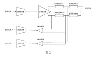
- FIG. 2 is a schematic diagram of the structure of a system control module in an embodiment of the present invention.
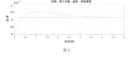
- FIG. 3 is a schematic diagram of the parameter tracking result of the inductor in an embodiment of the present invention.
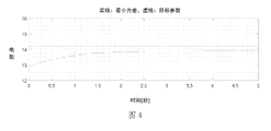
- FIG. 4 is a schematic diagram of the tracking results of resistance parameters in an embodiment of the present invention.
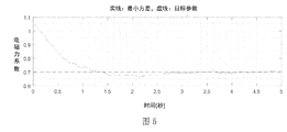
- Fig. 5 is a schematic diagram of the parameter tracking result of the electromagnetic force coefficient in an embodiment of the present invention.
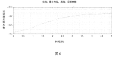
- Fig. 6 is a schematic diagram of parameter tracking results of filter feedback coefficients in an embodiment of the present invention.
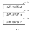
- Fig. 7 is a structural block diagram of a motor parameter tracking system in an embodiment of the present invention.
- Fig. 1 is a flowchart of a motor parameter tracking method in an embodiment.
- the motor parameter tracking method can be applied to a motor parameter tracking system.
- the motor can be a linear motor, that is, a linear resonant actuator, which refers to A vibration motor that generates an oscillating force on a single axis.
- the motor can be a linear motor used in electronic devices such as smart phones, tablet computers, and smart wearable devices.
- the motor parameter tracking method includes the following steps 102 to 106:
- Step 102 Excite the motor to work through the voltage excitation signal, and obtain the actual voltage and actual current at both ends of the motor in the working state.
- the voltage excitation signal refers to the electrical signal input to the working circuit of the motor in order to observe the characteristics of the motor.
- the voltage excitation signal is a digital signal, for example, the voltage excitation signal may be white noise.
- the motor parameter tracking system includes a system control module.
- the system control module Through the system control module, the voltage excitation signal is converted into an analog signal by a digital-to-analog converter, and then the analog signal is amplified by a power amplifier.
- the analog signal excites the motor to work, and while the motor is excited to work, the actual voltage and actual current at both ends of the motor in the working state are collected.
- the system control module is mainly composed of hardware equipment related to signal acquisition. The purpose is to measure and obtain the actual voltage v across the motor under working conditions. cm and the actual current i cm .
- the system control module includes a DAC digital-to-analog converter, ADC analog-to-digital converter, and a power amplifier. First, the voltage excitation signal signal is converted into an analog signal through the DAC digital-to-analog converter, and then the analog signal is processed by the power amplifier. Amplify, stimulate the motor to work through the amplified analog signal.
- the current signal is collected through the sampling resistor R shunt , the voltage signal is collected through the sampling resistor R lead , and the voltage signal and current are respectively converted through the ADC analog-to-digital converter.
- the signal is converted from an analog signal to a digital signal to obtain the actual voltage v cm and the actual current i cm at both ends of the motor in the working state.
- Step 104 Model the voltage error of the motor based on the actual voltage and actual current to obtain a voltage error function of the motor.
- the voltage error function is obtained according to the difference between the actual voltage at different sampling points and the predicted voltage at different sampling points, that is, the voltage error function is defined as the time error between the predicted voltage and the actual voltage.
- the voltage error function is calculated; where n is the sampling point index, v cm is the actual voltage, and v cp is the predicted voltage.
- predicted voltage in formula (1) can be calculated according to the motor parameters and the motor model, specifically according to the formula
- n is the sampling point index
- Reb is the resistance of the motor
- i cm is the actual current
- Leb is the inductance of the motor
- ⁇ 0 is the electromagnetic force coefficient
- u d is the vibrator speed of the motor.
- n is the sampling point index
- i cm is the actual current
- T s is the digital signal sampling period.
- u d [n] ⁇ u [n]f c ⁇ p [n]- ⁇ u [n]f c ⁇ p [n-2]-a 1 [n]u d [n-1]-a 2 [ n]u d [n-2] (4);
- n is the sampling point index
- ⁇ u , a 1 and a 2 are the coefficients of the second-order motor model
- f c ⁇ p is the electromagnetic force
- n is the sampling point index
- ⁇ 0 is the electromagnetic force coefficient
- i cm is the actual current.
- Step 106 Perform an iterative operation on the motor parameters according to the voltage error function and the preset iteration step length, so as to realize dynamic tracking of the motor parameters.
- this embodiment dynamically tracks motor parameters based on a voltage error function and an NLMS (Normalized Least Mean Square, normalized least mean square adaptive filtering) algorithm. That is, the normalized minimum mean square adaptive filtering is performed based on the error signal of the actual voltage v cm at both ends of the motor and the predicted voltage v cp .
- NLMS Normalized Least Mean Square, normalized least mean square adaptive filtering
- the same preset iteration step is set for the motor parameters, and the NLMS algorithm is used to iteratively calculate the motor parameters according to the iteration step of the motor parameters and the gradient of the voltage error function, so as to obtain the tracking result of the motor parameters.
- the NLMS algorithm does not need to set the iterative step length for each motor parameter separately, just set the same step length value for all the motor parameters, which not only reduces the difficulty of tuning parameters, but also reduces the sensitivity of the algorithm to the parameters. Sex.
- the motor parameters include resistance, inductance, filter feedback coefficient and electromagnetic force coefficient.
- the meaning and calculation formula of each motor parameter are as follows:
- the resistance calculation formula and tracking result are:
- Reb is the resistance
- n is the sampling point index
- ⁇ is the iteration step size
- frame_sanple is the total number of samples in each frame
- m is the sample index in each frame
- ⁇ oev is the voltage error function
- i cm is the actual current
- L eb is the inductance
- n is the sampling point index
- ⁇ is the iteration step size
- frame_sanple is the total number of samples in each frame
- m is the sample index in each frame
- ⁇ oev is the voltage error function
- i cm is the actual current
- ⁇ 0 is the electromagnetic force coefficient
- n is the sampling point index
- ⁇ is the iteration step size
- frame_sanple is the total number of samples per frame
- m is the sample index per frame
- ⁇ oev is the voltage error function
- u d is the vibrator speed of the motor
- the motor parameter tracking method uses a voltage excitation signal to excite the motor to work, obtain the actual voltage and actual current at both ends of the motor in the working state, and model the voltage error of the motor based on the actual voltage and actual current to obtain the motor According to the voltage error function and the preset iterative step length, the motor parameters are iteratively calculated to achieve dynamic tracking of the motor parameters.
- the motor parameter tracking method it is possible to adaptively adjust the differences between batches and individual motors, and dynamically track parameter changes caused by changes in motor temperature, attitude, etc., and only need to set all motor parameters
- the same step value not only reduces the difficulty of tuning parameters, but also reduces the sensitivity of the algorithm to parameters.
- parameters of the linear motor are tracked on an experimental device that includes the linear motor. Specifically, white noise is used as the voltage excitation signal, and the motor parameter tracking system is run. The frame is the unit and the NLMS algorithm is used to The motor parameters of the linear motor are tracked.
- Figures 3 to 6 show the motor parameter tracking results of inductance, resistance, electromagnetic force coefficient, and filter feedback coefficient.
- the solid lines in each figure represent the algorithm tracking parameters.
- the initial values of the algorithm tracking parameters can be set arbitrarily according to the system, and the dotted lines indicate Motor rated design parameters. Comparing the algorithm tracking results in Figures 3 to 6 with the design parameters, it can be concluded that the algorithm tracking parameters of each motor parameter gradually approach the rated design parameters of the motor over time, that is, the motor parameter tracking method in this embodiment Effectively realize the dynamic tracking of motor parameters.
- FIG. 7 it is a structural block diagram of the motor parameter tracking system in an embodiment.
- the system includes a system control module 710, a system identification module 720, and a parameter tracking module. 730.
- the system control module 710 is configured to excite the motor to work through a voltage excitation signal, and obtain the actual voltage and actual current at both ends of the motor in the working state.
- the system identification module 720 is configured to model the voltage error of the motor based on the actual voltage and actual current to obtain the voltage error function of the motor.
- the parameter tracking module 730 is configured to perform an iterative operation on the motor parameters according to the voltage error function and the preset iteration step length, so as to implement dynamic tracking of the motor parameters.
- the motor parameter tracking system provided by this embodiment can adaptively adjust the differences between batches and individuals of motors, and can dynamically track parameter changes caused by changes in motor temperature, attitude, etc., and only needs to be used for all motors. Setting the same step value for the parameters not only reduces the difficulty of tuning parameters, but also reduces the sensitivity of the algorithm to the parameters.
- the embodiment of the present invention also provides a terminal.
- the terminal includes a motor and a motor parameter tracking system that controls the motor, and also includes a memory and a processor.
- the memory stores a computer program that is processed by the computer program.
- the processor is caused to execute the motor parameter tracking method described in the foregoing embodiments.
- the embodiment of the present invention also provides a computer-readable storage medium.
- One or more non-volatile computer-readable storage media containing computer-executable instructions when the computer-executable instructions are executed by one or more processors, cause the processors to execute as described in the foregoing embodiments Describe the motor parameter tracking method.
- the embodiment of the present invention also provides a computer program product.
- a computer program product containing instructions, when it runs on a computer, causes the computer to execute the motor parameter tracking method described in the foregoing embodiments.
Landscapes
- Engineering & Computer Science (AREA)
- Power Engineering (AREA)
- Control Of Electric Motors In General (AREA)
Abstract
一种马达参数追踪方法及系统,该方法通过电压激励信号激励马达工作,获取处于工作状态下的所述马达两端的实际电压和实际电流;基于所述实际电压和实际电流对所述马达的电压误差进行建模,得到所述马达的电压误差函数;根据所述电压误差函数和预设迭代步长对马达参数进行迭代运算,以实现对所述马达参数的动态追踪。通过上述马达参数追踪方法,能够对于马达的批次和个体之间的差异进行自适应调整,能够动态跟踪由于马达温度、姿态等方面变化而引起的参数变化,并且只需为所有马达参数设定同一步长值,不仅降低了调参的难度,而且降低了算法对参数的敏感性。
Description
本发明涉及微机电领域,特别是涉及一种马达参数追踪方法及系统。
随着智能手机、智能穿戴等各类消费电子设备的发展普及,人们对触觉体验的要求也与日俱增。通过线性马达(LRA)可以提供丰富的振感体验,且马达的振动性能对触觉体验有着直接且较大的影响。在实际应用中,马达单体的状态和参数会受其不同生产批次、不同应用场境、不同变换姿态的影响而产生意想不到的差异变化。因此,为了消除马达单体状态和参数的变化对触觉体验的不利影响,实现对马达单体进行参数追踪和反馈控制就显得尤为重要。
常规的马达参数追踪方法通过预设的马达参数来进行马达激励信号控制,通常称为开环控制技术。该技术实现简单且不需要复杂的控制理论,但是对于马达批次和个体之间的差异无法进行自适应调整,同时也无法有效跟踪由于马达温度、姿态等方面变化而引起的参数变化。
因此,有必要提供一种能够对于马达的批次和个体之间的差异进行自适应调整的马达参数追踪方法及系统。
【发明内容】
本发明的目的在于提供一种能够对于马达的批次和个体之间的差异进行自适应调整的马达参数追踪方法及系统。
本发明的技术方案如下:一种马达参数追踪方法,包括:
通过电压激励信号激励马达工作,获取处于工作状态下的所述马达两端的实际电压和实际电流;
基于所述实际电压和实际电流对所述马达的电压误差进行建模,得到所述马达的电压误差函数;
根据所述电压误差函数和预设迭代步长对马达参数进行迭代运算,以实现对所述马达参数的动态追踪。
可选的,在其中一个实施例中,所述电压激励信号为数字信号,所述通过电压激励信号激励马达工作,包括:
将所述电压激励信号经过数模转换器将数字信号转为模拟信号,然后经过功率放大器对所述模拟信号进行放大,通过放大后的所述模拟信号激励所述马达工作。
可选的,在其中一个实施例中,所述基于所述实际电压和实际电流对所述马达的电压误差进行建模,得到所述马达的电压误差函数,包括:
根据不同采样点的实际电压与不同采样点的预测电压之间的差得到所述电压误差函数,其中所述预测电压根据所述马达参数和马达模型计算得出。
可选的,在其中一个实施例中,所述根据不同采样点的实际电压与不同采样点的预测电压之间的差得到所述电压误差函数包括:
根据公式
ε
oev[n]=v
cm[n]-v
cp[n]
计算出所述电压误差函数;其中,n为采样点索引,v
cm为实际电压,v
cp为预测电压。
可选的,在其中一个实施例中,所述预测电压根据所述马达参数和马达模型计算得出,包括:
根据公式

计算出所述预测电压;其中,n为采样点索引,R
eb为马达的电阻,i
cm为实际电流,L
eb为马达的电感,φ
0为电磁力系数,u
d为马达的振子速度。
可选的,在其中一个实施例中,所述马达的振子速度根据公式
u
d[n]=σ
u[n]f
c·p[n]-σ
u[n]f
c·p[n-2]-a
1[n]u
d[n-1]-a
2[n]u
d[n-2]
计算得出,其中,n为采样点索引,σ
u、a
1和a
2为马达二阶模型的系数,f
c·p为电磁力。
可选的,在其中一个实施例中,所述电磁力根据公式
f
c·p[n]=φ
0[n]i
c·m[n]
计算得出,其中,n为采样点索引,φ
0为电磁力系数,i
cm为实际电流。
可选的,在其中一个实施例中,为所述马达参数设置同一个预设迭代步长;所述根据所述电压误差函数和预设迭代步长对马达参数进行迭代运算,以实现对所述马达参数的动态追踪,包括:
基于所述电压误差函数和所述预设迭代步长对所述马达参数进行归一化最小均方自适应滤波,得到所述马达参数的追踪结果。
可选的,在其中一个实施例中,所述马达参数包括电阻、电感、滤波器反馈系数和电磁力系数;
所述电阻的追踪结果为:

其中,R
eb为电阻,n为采样点索引,μ为迭代步长,frame_sanple为每帧的样本总数,m为每帧样本索引,ε
oev为电压误差函数,i
cm为实际电流,其中u[m]=-i
cm[m];
所述电感的追踪结果为:

其中,L
eb为电感,n为采样点索引,μ为迭代步长,frame_sanple为每帧的样本总数,m为每帧样本索引,ε
oev为电压误差函数,i
cm为实际电流,其中

所述滤波器反馈系数的追踪结果为:

其中,a
k为滤波器反馈系数,包括a
1和a
2,n为采样点索引,μ为迭代步长,frame_sanple为每帧的样本总数,m为每帧样本索引,ε
oev为电压误差函数,φ
0为电磁力系数,其中u[m]=-φ
0[m]α
k[m];
所述电磁力系数的追踪结果为:

其中,φ
0为电磁力系数,n为采样点索引,μ为迭代步长,frame_sanple为每帧的样本总数,m为每帧样本索引,ε
oev为电压误差函数,u
d为马达的振子速度,其中

一种马达参数追踪系统,包括:
系统控制模块,用于通过电压激励信号激励马达工作,获取处于工作状态下的所述马达两端的实际电压和实际电流;
系统辨识模块,用于基于所述实际电压和实际电流对所述马达的电压误差进行建模,得到所述马达的电压误差函数;
参数追踪模块,用于根据所述电压误差函数和预设迭代步长对马达参数进行迭代运算,以实现对所述马达参数的动态追踪。
一种终端,包括马达及控制所述马达的马达参数追踪系统,还包括存储器及处理器,所述存储器中储存有计算机程序,所述计算机程序被所述处理器执行时,使得所述处理器执行上述的方法的步骤。
一种计算机可读存储介质,其上存储有计算机程序,其特征在于,所述计算机程序被处理器执行时实现上述的方法的步骤。
本发明的有益效果在于:通过电压激励信号激励马达工作,获取处于工作状态下的马达两端的实际电压和实际电流,基于实际电压和实际电流对马达的电压误差进行建模,得到马达的电压误差函数,据电压误差函数和预设迭代步长对马达参数进行迭代运算,以实现对马达参数的动态追踪。通过上述马达参数追踪方法,能够对于马达的批次和个体之间的差异进行自适应调整,能够动态跟踪由于马达温度、姿态等方面变化而引起的参数变化,并且只需为所有马达参数设定同一步长值,不仅降低了调参的难度,而且降低了算法对参数的敏感性。
图1为本发明一个实施例中马达参数追踪方法的流程图;
图2为本发明一个实施例中系统控制模块的结构示意图;
图3为本发明一个实施例中电感的参数追踪结果示意图;
图4为本发明一个实施例中电阻的参数追踪结果示意图;
图5为本发明一个实施例中电磁力系数的参数追踪结果示意图;
图6为本发明一个实施例中滤波器反馈系数的参数追踪结果示意图;
图7为本发明一个实施例中马达参数追踪系统的结构框图。
下面结合附图和实施方式对本发明作进一步说明。
图1为一个实施例中马达参数追踪方法的流程图,该马达参数追踪方法可以应用于马达参数追踪系统中,具体的,该马达可以是线性马达,也即是线性谐振传动器,指的是在单个轴上产生振荡力的振动电机,更为具体的,该马达可以是应用于智能手机、平板电脑、智能穿戴式设备等电子设备中的线性马达。通过该马达参数追踪方法,能够对于马达的批次和个体之间的差异进行自适应调整,实现对马达参数的动态追踪。如图1所示,该马达参数追踪方法包括以下步骤102至步骤106:
步骤102:通过电压激励信号激励马达工作,获取处于工作状态下的所述马达两端的实际电压和实际电流。
电压激励信号指的是为了观测马达的特性而输入到马达的工作电路中的电信号,本实施例中电压激励信号为数字信号,例如该电压激励信号可以是白噪声。
具体的,马达参数追踪系统包括系统控制模块,通过系统控制模块将所述电压激励信号经过数模转换器将数字信号转为模拟信号,然后经过功率放大器对所述模拟信号进行放大,通过放大后的所述模拟信号激励所述马达工作,激励马达工作的同时,采集处于工作状态下的马达两端的实际电压和实际电流。
举例说明,如图2所示,为一个实施例中系统控制模块的结构示意图,该系统控制模块主要由信号采集相关的硬件设备组成,目的是测量并获取工作状态下的马达两端的实际电压v
cm和实际电流i
cm。具体的,该系统控制模块包括DAC数模转换器、ADC模数转换器和功率放大器,首先将电压激励信号signal经过DAC数模转换器将数字信号转为模拟信号,然后经过功率放大器对模拟信号进行放大,通过放大后的模拟信号激励马达工作,激励马达工作的同时,通过采样电阻R
shunt采集电流信号,通过采样电阻R
lead 采集电压信号,并分别通过ADC模数转换器将电压信号和电流信号由模拟信号转换为数字信号,以获取处于工作状态下的马达两端的实际电压实际电压v
cm和实际电流i
cm。
步骤104:基于所述实际电压和实际电流对所述马达的电压误差进行建模,得到所述马达的电压误差函数。
其中,根据不同采样点的实际电压与不同采样点的预测电压之间的差得到所述电压误差函数,也即电压误差函数定义为预测电压与实际电压时间的误差。
具体的,根据公式
ε
oev[n]=v
cm[n]-v
cp[n] (1)
计算出所述电压误差函数;其中,n为采样点索引,v
cm为实际电压,v
cp为预测电压。
进一步的,式(1)中的预测电压可以根据马达参数和马达模型计算得出,具体根据公式

计算出预测电压;其中,n为采样点索引,R
eb为马达的电阻,i
cm为实际电流,L
eb为马达的电感,φ
0为电磁力系数,u
d为马达的振子速度。
式(2)中电流对时间的导数
 采用如下公式计算:

其中,n为采样点索引,i
cm为实际电流,T
s为数字信号采样周期。
式(2)中马达的振子速度u
d采用如下公式计算:
u
d[n]=σ
u[n]f
c·p[n]-σ
u[n]f
c·p[n-2]-a
1[n]u
d[n-1]-a
2[n]u
d[n-2] (4);
其中,n为采样点索引,σ
u、a
1和a
2为马达二阶模型的系数,f
c·p为电磁力。
式(4)中电磁力f
c·p按如下公式计算:
f
c·p[n]=φ
0[n]i
c·m[n](5);
其中,n为采样点索引,φ
0为电磁力系数,i
cm为实际电流。
步骤106:根据所述电压误差函数和预设迭代步长对马达参数进行迭代运算,以实现对所述马达参数的动态追踪。
其中,本实施例基于电压误差函数和NLMS(Normalized Least Mean Square,归一化最小均方自适应滤波)算法对马达参数进行动态追踪。也即基于马达两端实际电压v
cm和预测电压v
cp的误差信号进行归一化最小均方自适应滤波。
具体的,为马达参数设置同一个预设迭代步长,利用NLMS算法根据马达参数的迭代步长及电压误差函数的梯度对马达参数进行迭代运算,从而得到马达参数的追踪结果。需要说明的是,NLMS算法不需要为各个马达参数分别设置迭代步长,只需为所有马达参数设定同一步长值即可,不仅降低了调参的难度,而且降低了算法对参数的敏感性。
以下作为具体举例说明,马达参数包括电阻、电感、滤波器反馈系数和电磁力系数,NLMS算法在逐帧迭代运算过程中,各个马达参数含义及计算公式如下所述:
电阻的计算公式及追踪结果为:


其中,R
eb为电阻,n为采样点索引,μ为迭代步长,frame_sanple为每帧的样本总数,m为每帧样本索引,ε
oev为电压误差函数,i
cm为实际电流,式(7)中u[m]=-i
cm[m]。
电感的计算公式及追踪结果为:


其中,L
eb为电感,n为采样点索引,μ为迭代步长,frame_sanple为每帧的样本总数,m为每帧样本索引,ε
oev为电压误差函数,i
cm为实际电流,式(9)中

滤波器反馈系数的计算公式及追踪结果为:


其中,a
k为滤波器反馈系数,包括a
1和a
2,n为采样点索引,μ为迭代步长,frame_sanple为每帧的样本总数,m为每帧样本索引,ε
oev为电压误差函数,φ
0为电磁力系数,式(12)中u[m]=-φ
0[m]α
k[m]。
电磁力系数的计算公式及追踪结果为:


其中,φ
0为电磁力系数,n为采样点索引,μ为迭代步长,frame_sanple为每帧的样本总数,m为每帧样本索引,ε
oev为电压误差函数,u
d为马达的振子速度,式(15)中

本实施例提供的马达参数追踪方法,通过电压激励信号激励马达工作,获取处于工作状态下的马达两端的实际电压和实际电流,基于实际电压和实际电流对马达的电压误差进行建模,得到马达的电压误差函数,据电压误差函数和预设迭代步长对马达参数进行迭代运算,以实现对马达参数的动态追踪。通过上述马达参数追踪方法,能够对于马达的批次和个体之间的差异进行自适应调整,能够动态跟踪由于马达温度、姿态等方面变化而引起的参数变化,并且只需为所有马达参数设定同一步长值,不仅降低了调参的难度,而且降低了算法对参数的敏感性。
在一个实施例中,在包含有线性马达的实验设备上对该线性马达进行参数追踪,具体的,采用白噪声作为电压激励信号,运行马达参数追踪系 统,以帧为单位,通过NLMS算法对该线性马达的马达参数进行追踪。
NLMS算法中部分参数设置如下表1所示,其中原始信号采样率可以理解为激励信号的采样频率,NLMS信号采样率可以理解为NLMS算法的采样频率。
表1 NLMS算法参数
| 参数 | 单位 | 设置值 |
| 原始信号采样率 | Hz | 48000 |
| NLMS信号采样率 | Hz | 4000 |
| 帧长 | ms | 44 |
| 参数步长 | / | 0.07 |
图3至图6分别为电感、电阻、电磁力系数和滤波器反馈系数的马达参数追踪结果,其中各图中实线表示算法追踪参数,算法追踪参数的初始值可以根据系统任意设置,虚线表示马达额定设计参数。将图3至图6中的算法追踪结果与设计参数对比可以得出,各个马达参数的算法追踪参数随时间的变化逐渐趋近于马达额定设计参数,也即本实施例中的马达参数追踪方法有效实现了对马达参数的动态追踪。
基于相同的发明构思,以下提供一种马达参数追踪系统,如图7所示,为一个实施例中马达参数追踪系统的结构框图,该系统包括系统控制模块710、系统辨识模块720和参数追踪模块730。
系统控制模块710用于通过电压激励信号激励马达工作,获取处于工作状态下的所述马达两端的实际电压和实际电流。
系统辨识模块720用于基于所述实际电压和实际电流对所述马达的电压误差进行建模,得到所述马达的电压误差函数。
参数追踪模块730用于根据所述电压误差函数和预设迭代步长对马达参数进行迭代运算,以实现对所述马达参数的动态追踪。
本实施例提供的马达参数追踪系统,能够对于马达的批次和个体之间的差异进行自适应调整,能够动态跟踪由于马达温度、姿态等方面变化而引起的参数变化,并且只需为所有马达参数设定同一步长值,不仅降低了 调参的难度,而且降低了算法对参数的敏感性。
本发明实施例还提供了一种终端,该终端包括马达及控制所述马达的马达参数追踪系统,还包括存储器及处理器,所述存储器中储存有计算机程序,所述计算机程序被所述处理器执行时,使得所述处理器执行如上述各实施例中所描述的马达参数追踪方法。
本发明实施例还提供了一种计算机可读存储介质。一个或多个包含计算机可执行指令的非易失性计算机可读存储介质,当所述计算机可执行指令被一个或多个处理器执行时,使得所述处理器执行如上述各实施例中所描述的马达参数追踪方法。
本发明实施例还提供了一种计算机程序产品。一种包含指令的计算机程序产品,当其在计算机上运行时,使得计算机执行上述各实施例中所描述的马达参数追踪方法。
以上所述的仅是本发明的实施方式,在此应当指出,对于本领域的普通技术人员来说,在不脱离本发明创造构思的前提下,还可以做出改进,但这些均属于本发明的保护范围。
Claims (12)
- 一种马达参数追踪方法,其特征在于,包括:通过电压激励信号激励马达工作,获取处于工作状态下的所述马达两端的实际电压和实际电流;基于所述实际电压和实际电流对所述马达的电压误差进行建模,得到所述马达的电压误差函数;根据所述电压误差函数和预设迭代步长对马达参数进行迭代运算,以实现对所述马达参数的动态追踪。
- 根据权利要求1所述的方法,其特征在于,所述电压激励信号为数字信号,所述通过电压激励信号激励马达工作,包括:将所述电压激励信号经过数模转换器将数字信号转为模拟信号,然后经过功率放大器对所述模拟信号进行放大,通过放大后的所述模拟信号激励所述马达工作。
- 根据权利要求1所述的方法,其特征在于,所述基于所述实际电压和实际电流对所述马达的电压误差进行建模,得到所述马达的电压误差函数,包括:根据不同采样点的实际电压与不同采样点的预测电压之间的差得到所述电压误差函数,其中所述预测电压根据所述马达参数和马达模型计算得出。
- 根据权利要求3所述的方法,其特征在于,所述根据不同采样点的实际电压与不同采样点的预测电压之间的差得到所述电压误差函数包括:根据公式ε oev[n]=v cm[n]-v cp[n]计算出所述电压误差函数;其中,n为采样点索引,v cm为实际电压,v cp 为预测电压。
- 根据权利要求4所述的方法,其特征在于,所述预测电压根据所述马达参数和马达模型计算得出,包括:根据公式
 计算出所述预测电压;其中,n为采样点索引,R eb为马达的电阻,i cm为实际电流,L eb为马达的电感,φ 0为电磁力系数,u d为马达的振子速度。
 - 根据权利要求5所述的方法,其特征在于,所述马达的振子速度根据公式u d[n]=σ u[n]f c·p[n]-σ u[n]f c·p[n-2]-a 1[n]u d[n-1]-a 2[n]u d[n-2]计算得出,其中,n为采样点索引,σ u、a 1和a 2为马达二阶模型的系数,f c·p为电磁力。
- 根据权利要求6所述的方法,其特征在于,所述电磁力根据公式f c·p[n]=φ 0[n]i c·m[n]计算得出,其中,n为采样点索引,φ 0为电磁力系数,i cm为实际电流。
- 根据权利要求1所述的方法,其特征在于,为所述马达参数设置同一个预设迭代步长;所述根据所述电压误差函数和预设迭代步长对马达参数进行迭代运算,以实现对所述马达参数的动态追踪,包括:基于所述电压误差函数和所述预设迭代步长对所述马达参数进行归一化最小均方自适应滤波,得到所述马达参数的追踪结果。
- 根据权利要求8所述的方法,其特征在于,所述马达参数包括电阻、电感、滤波器反馈系数和电磁力系数;所述电阻的追踪结果为:
 其中,R eb为电阻,n为采样点索引,μ为迭代步长,frame_sanple为每帧的样本总数,m为每帧样本索引,ε oev为电压误差函数,i cm为实际电流,其中u[m]=-i cm[m];所述电感的追踪结果为:
 其中,L eb为电感,n为采样点索引,μ为迭代步长,frame_sanple为每帧的样本总数,m为每帧样本索引,ε oev为电压误差函数,i cm为实际电流,其中
 所述滤波器反馈系数的追踪结果为:
 其中,a k为滤波器反馈系数,包括a 1和a 2,n为采样点索引,μ为迭代 步长,frame_sanple为每帧的样本总数,m为每帧样本索引,ε oev为电压误差函数,φ 0为电磁力系数,其中u[m]=-φ 0[m]α k[m];所述电磁力系数的追踪结果为:
 其中,φ 0为电磁力系数,n为采样点索引,μ为迭代步长,frame_sanple为每帧的样本总数,m为每帧样本索引,ε oev为电压误差函数,u d为马达的振子速度,其中
- 一种马达参数追踪系统,其特征在于,包括:系统控制模块,用于通过电压激励信号激励马达工作,获取处于工作状态下的所述马达两端的实际电压和实际电流;系统辨识模块,用于基于所述实际电压和实际电流对所述马达的电压误差进行建模,得到所述马达的电压误差函数;参数追踪模块,用于根据所述电压误差函数和预设迭代步长对马达参数进行迭代运算,以实现对所述马达参数的动态追踪。
- 一种终端,其特征在于,包括马达及控制所述马达的马达参数追踪系统,还包括存储器及处理器,所述存储器中储存有计算机程序,所述计算机程序被所述处理器执行时,使得所述处理器执行如权利要求1至9中任一项所述的方法的步骤。
- 一种计算机可读存储介质,其上存储有计算机程序,其特征在于, 所述计算机程序被处理器执行时实现如权利要求1至9中任一项所述的方法的步骤。
Priority Applications (3)
| Application Number | Priority Date | Filing Date | Title |
|---|---|---|---|
| PCT/CN2019/093505 WO2020258202A1 (zh) | 2019-06-28 | 2019-06-28 | 马达参数追踪方法及系统 |
| CN201910590926.3A CN110350828B (zh) | 2019-06-28 | 2019-07-02 | 马达参数追踪方法及系统 |
| US16/993,304 US11211888B2 (en) | 2019-06-28 | 2020-08-14 | Motor parameter tracking method and motor parameter tracking system |
Applications Claiming Priority (1)
| Application Number | Priority Date | Filing Date | Title |
|---|---|---|---|
| PCT/CN2019/093505 WO2020258202A1 (zh) | 2019-06-28 | 2019-06-28 | 马达参数追踪方法及系统 |
Related Child Applications (1)
| Application Number | Title | Priority Date | Filing Date |
|---|---|---|---|
| US16/993,304 Continuation US11211888B2 (en) | 2019-06-28 | 2020-08-14 | Motor parameter tracking method and motor parameter tracking system |
Publications (1)
| Publication Number | Publication Date |
|---|---|
| WO2020258202A1 true WO2020258202A1 (zh) | 2020-12-30 |
Family
ID=68177362
Family Applications (1)
| Application Number | Title | Priority Date | Filing Date |
|---|---|---|---|
| PCT/CN2019/093505 Ceased WO2020258202A1 (zh) | 2019-06-28 | 2019-06-28 | 马达参数追踪方法及系统 |
Country Status (3)
| Country | Link |
|---|---|
| US (1) | US11211888B2 (zh) |
| CN (1) | CN110350828B (zh) |
| WO (1) | WO2020258202A1 (zh) |
Families Citing this family (6)
| Publication number | Priority date | Publication date | Assignee | Title |
|---|---|---|---|---|
| CN111965537B (zh) * | 2020-06-30 | 2021-10-08 | 瑞声新能源发展(常州)有限公司科教城分公司 | 马达参数测试方法 |
| CN112769367B (zh) * | 2021-01-07 | 2022-08-26 | 山东交通学院 | 永磁直线电机数据驱动离散迭代积分滑模控制方法及系统 |
| CN115708113A (zh) * | 2021-08-05 | 2023-02-21 | 上海宝信软件股份有限公司 | 适用于热镀锌机组带钢延展的数据对齐方法和系统、设备 |
| CN115483865B (zh) * | 2022-08-31 | 2024-11-05 | 歌尔股份有限公司 | 马达振子的碰撞保护方法、装置、终端设备及存储介质 |
| CN116953510A (zh) * | 2023-07-12 | 2023-10-27 | 瑞声开泰声学科技(上海)有限公司 | 一种马达个体参数确定方法、装置、设备及存储介质 |
| CN119154740B (zh) * | 2024-09-27 | 2025-05-09 | 哈尔滨工业大学 | 一种永磁同步电机过调制弱磁区电感参数在线辨识与自适应滤波方法和系统 |
Citations (5)
| Publication number | Priority date | Publication date | Assignee | Title |
|---|---|---|---|---|
| US7230403B2 (en) * | 2003-04-29 | 2007-06-12 | International Rectifier Corporation | System and method for elimination of DC offset feedback in AC drives |
| CN103036498A (zh) * | 2012-10-18 | 2013-04-10 | 中国电力科学研究院 | 一种基于pmu的同步发电机实用模型参数校核与辨识方法 |
| CN106068007A (zh) * | 2016-06-07 | 2016-11-02 | 瑞声科技(新加坡)有限公司 | 扬声器非线性系统辨识方法 |
| CN109274308A (zh) * | 2018-08-13 | 2019-01-25 | 瑞声科技(新加坡)有限公司 | 马达参数控制系统及马达参数控制方法 |
| CN109672383A (zh) * | 2018-12-25 | 2019-04-23 | 北京理工大学 | 一种凸极式永磁同步电机在线参数辨识方法 |
Family Cites Families (9)
| Publication number | Priority date | Publication date | Assignee | Title |
|---|---|---|---|---|
| US20130307441A1 (en) * | 2012-05-21 | 2013-11-21 | Motorola Mobility, Inc. | System and Method for Control of Linear and Rotary Vibrators in an Electronic Device |
| US8800302B2 (en) * | 2012-07-16 | 2014-08-12 | Sunpower, Inc. | Driving an active vibration balancer to minimize vibrations at the fundamental and harmonic frequencies |
| US9966891B2 (en) * | 2016-03-16 | 2018-05-08 | Mitsubishi Electric Research Laboratories, Inc. | System and method for controlling speed of electric motor |
| CN205754098U (zh) * | 2016-06-28 | 2016-11-30 | 浙江理工大学 | 基于改进adrc自抗扰算法的永磁直线电机控制系统 |
| US10193505B2 (en) * | 2016-08-05 | 2019-01-29 | Cirrus Logic, Inc. | Configurable control loop topology for a pulse width modulation amplifier |
| CN108696199B (zh) * | 2018-05-29 | 2020-12-04 | 合肥工业大学 | 一种提高永磁同步直线电机位置精度的控制方法 |
| US10348282B1 (en) * | 2018-07-31 | 2019-07-09 | Cirrus Logic, Inc. | Modulators |
| US10564728B1 (en) * | 2018-09-10 | 2020-02-18 | Apple Inc. | Gravity-induced position offset tracking for dynamic management of haptic module mechanical offset |
| US11533011B2 (en) * | 2020-03-04 | 2022-12-20 | Qualcomm Incorporated | Actuator driver circuit with self-resonance tracking |
-
2019
- 2019-06-28 WO PCT/CN2019/093505 patent/WO2020258202A1/zh not_active Ceased
- 2019-07-02 CN CN201910590926.3A patent/CN110350828B/zh active Active
-
2020
- 2020-08-14 US US16/993,304 patent/US11211888B2/en not_active Expired - Fee Related
Patent Citations (5)
| Publication number | Priority date | Publication date | Assignee | Title |
|---|---|---|---|---|
| US7230403B2 (en) * | 2003-04-29 | 2007-06-12 | International Rectifier Corporation | System and method for elimination of DC offset feedback in AC drives |
| CN103036498A (zh) * | 2012-10-18 | 2013-04-10 | 中国电力科学研究院 | 一种基于pmu的同步发电机实用模型参数校核与辨识方法 |
| CN106068007A (zh) * | 2016-06-07 | 2016-11-02 | 瑞声科技(新加坡)有限公司 | 扬声器非线性系统辨识方法 |
| CN109274308A (zh) * | 2018-08-13 | 2019-01-25 | 瑞声科技(新加坡)有限公司 | 马达参数控制系统及马达参数控制方法 |
| CN109672383A (zh) * | 2018-12-25 | 2019-04-23 | 北京理工大学 | 一种凸极式永磁同步电机在线参数辨识方法 |
Also Published As
| Publication number | Publication date |
|---|---|
| CN110350828B (zh) | 2023-05-02 |
| CN110350828A (zh) | 2019-10-18 |
| US20200412288A1 (en) | 2020-12-31 |
| US11211888B2 (en) | 2021-12-28 |
Similar Documents
| Publication | Publication Date | Title |
|---|---|---|
| WO2020258202A1 (zh) | 马达参数追踪方法及系统 | |
| CN110266223B (zh) | 马达的振动控制系统、方法以及电子设备 | |
| CN105916079B (zh) | 一种扬声器非线性补偿方法及装置 | |
| CN109274308B (zh) | 马达参数控制系统及马达参数控制方法 | |
| CN111478630B (zh) | 一种马达稳态单频失真补偿方法及装置 | |
| CN108668197A (zh) | 扬声器系统的控制方法及装置 | |
| CN112491323A (zh) | 线性马达超行程控制方法、装置、计算机设备及存储介质 | |
| CN110995079A (zh) | 电机振动信号的生成方法、装置、终端及存储介质 | |
| WO2020211105A1 (zh) | 一种马达驱动信号设置方法、电子设备及存储介质 | |
| CN105120414A (zh) | 智能音频管理系统 | |
| CN115242157A (zh) | 马达振子的位移限制方法、装置、终端设备及存储介质 | |
| CN114006565A (zh) | 马达控制方法、装置、设备及计算机可读存储介质 | |
| CN105491726B (zh) | 一种自适应电流控制电路 | |
| CN113179044A (zh) | 一种压电陶瓷驱动器的迟滞补偿方法、系统及定位设备 | |
| WO2021097888A1 (zh) | 一种马达瞬态失真测量方法及系统 | |
| CN111030503B (zh) | 一种压电陶瓷的抗迟滞方法、装置、设备和介质 | |
| CN115844497B (zh) | 超声换能器的控制方法、装置、设备及存储介质 | |
| CN119853131B (zh) | 电动汽车v2g充电桩稳定控制方法、系统及电子设备 | |
| CN111243631A (zh) | 一种自动增益控制方法及电子设备 | |
| CN108170032B (zh) | 一种提高压电叠堆式驱动器定位精度的方法 | |
| US11799453B2 (en) | Adaptive control of capacitive load | |
| CN111222248B (zh) | 压电陶瓷致动器的迟滞现象确定方法和装置 | |
| US11183165B2 (en) | Electronic device, active noise reduction system, and active noise reduction method | |
| CN115021564A (zh) | 提高变换器动态响应的方法、装置、电子设备及存储介质 | |
| CN111007721A (zh) | 一种线性定常系统中采样周期动态选择方法 |
Legal Events
| Date | Code | Title | Description |
|---|---|---|---|
| 121 | Ep: the epo has been informed by wipo that ep was designated in this application |
Ref document number: 19935175 Country of ref document: EP Kind code of ref document: A1 |
|
| NENP | Non-entry into the national phase |
Ref country code: DE |
|
| 122 | Ep: pct application non-entry in european phase |
Ref document number: 19935175 Country of ref document: EP Kind code of ref document: A1 |