WO2020255955A1 - Electronic-component-accommodating container, electronic component series, method for manufacturing electronic-component-accommodating container, and method for manufacturing electronic component series - Google Patents
Electronic-component-accommodating container, electronic component series, method for manufacturing electronic-component-accommodating container, and method for manufacturing electronic component series Download PDFInfo
- Publication number
- WO2020255955A1 WO2020255955A1 PCT/JP2020/023580 JP2020023580W WO2020255955A1 WO 2020255955 A1 WO2020255955 A1 WO 2020255955A1 JP 2020023580 W JP2020023580 W JP 2020023580W WO 2020255955 A1 WO2020255955 A1 WO 2020255955A1
- Authority
- WO
- WIPO (PCT)
- Prior art keywords
- main body
- cover sheet
- electronic component
- storage
- storage recess
- Prior art date
Links
Images


Classifications
-
- B—PERFORMING OPERATIONS; TRANSPORTING
- B65—CONVEYING; PACKING; STORING; HANDLING THIN OR FILAMENTARY MATERIAL
- B65D—CONTAINERS FOR STORAGE OR TRANSPORT OF ARTICLES OR MATERIALS, e.g. BAGS, BARRELS, BOTTLES, BOXES, CANS, CARTONS, CRATES, DRUMS, JARS, TANKS, HOPPERS, FORWARDING CONTAINERS; ACCESSORIES, CLOSURES, OR FITTINGS THEREFOR; PACKAGING ELEMENTS; PACKAGES
- B65D73/00—Packages comprising articles attached to cards, sheets or webs
- B65D73/02—Articles, e.g. small electrical components, attached to webs
-
- B—PERFORMING OPERATIONS; TRANSPORTING
- B65—CONVEYING; PACKING; STORING; HANDLING THIN OR FILAMENTARY MATERIAL
- B65D—CONTAINERS FOR STORAGE OR TRANSPORT OF ARTICLES OR MATERIALS, e.g. BAGS, BARRELS, BOTTLES, BOXES, CANS, CARTONS, CRATES, DRUMS, JARS, TANKS, HOPPERS, FORWARDING CONTAINERS; ACCESSORIES, CLOSURES, OR FITTINGS THEREFOR; PACKAGING ELEMENTS; PACKAGES
- B65D85/00—Containers, packaging elements or packages, specially adapted for particular articles or materials
- B65D85/30—Containers, packaging elements or packages, specially adapted for particular articles or materials for articles particularly sensitive to damage by shock or pressure
- B65D85/38—Containers, packaging elements or packages, specially adapted for particular articles or materials for articles particularly sensitive to damage by shock or pressure for delicate optical, measuring, calculating or control apparatus
Definitions
- the present invention relates to an electronic component storage container.
- the present invention also relates to an electronic component chain in which electronic components are stored in the electronic component storage container, a method for manufacturing the electronic component storage container, and a method for manufacturing the electronic component chain.
- the packaging form of electronic parts represented by a multilayer ceramic capacitor there is a packaging form in which a plurality of electronic parts are filled in a storage container.
- a method has been proposed in which a cover film is sealed on the upper surface of a portion where electronic components are housed by heat welding or the like.
- Patent Document 1 discloses a magazine (packaging body) for storing individualized electronic parts.
- the package described in Patent Document 1 includes a receiving structure (main body portion) having a plurality of cavities (storage recesses) along the longitudinal direction, and a cover structure (lid portion) arranged above the main body portion.
- the cover sheet is provided with a sealing foil (cover sheet) sandwiched between the main body and the lid, and the cover sheet is detachably connected to the main body.
- the circumference of the storage recess is supported by a support member such as a trowel holder, and the trowel or the like is pressed around the opening of the storage recess.
- a method of pressing the cover sheet with a tool is known.
- the height of the main body is uneven due to the variation in molding, the pressing jig is tilted with respect to the adhesive surface, or the main body is supported by being displaced from the fixed position of the support member.
- the air remaining inside the storage recess expands due to changes in the external environment such as temperature or atmospheric pressure, a part of the heat-welded cover sheet peels off, causing problems such as the sealed state cannot be maintained. There is a risk.
- the present invention has been made to solve the above problems, and an object of the present invention is to provide an electronic component storage container in which the adhesive strength of the cover sheet to the main body is uniform around the opening. Another object of the present invention is to provide an electronic component chain in which electronic components are stored in the electronic component storage container, a method for manufacturing the electronic component storage container, and a method for manufacturing the electronic component chain.
- a plurality of storage recesses for storing electronic components are arranged along the longitudinal direction, and each of the storage recesses has an opening on one side in the height direction, and a main body portion.
- a cover sheet that is detachably joined to the main body so as to cover the opening of the storage recess, and a lid that is arranged so as to sandwich the cover sheet between the main body.
- the main body portion has a raised portion that rises in a direction opposite to the depth direction of the storage recess around the opening, and the cover sheet has the shape of the raised portion. It is in contact with each other along the line and is detachably joined to the raised portion.
- the electronic component chain of the present invention includes the electronic component storage container of the present invention and the electronic component stored in the storage recess of the electronic component storage container.
- a main body in which a plurality of storage recesses for storing electronic components are arranged along the longitudinal direction, and each of the storage recesses has an opening on one side in the height direction.
- the step of detachably joining the cover sheet to the main body so as to cover the opening of each of the storage recesses of the portion, and the lid portion is arranged so as to sandwich the cover sheet between the main body and the main body. It is provided with a process of performing.
- the main body portion has a raised portion that rises in a direction opposite to the depth direction of the storage recess around the opening, and the cover sheet is peeled off from the main body portion.
- the steps of joining as possible are a step of supporting the periphery of the storage recess of the main body by a support member from the direction of having the storage recess, and a step of supporting the main body by the support member and raising the main body.
- the portion includes a step of pressing the cover sheet in the depth direction of the storage recess using a pressing jig.
- the periphery of the storage recess of the main body portion is supported by a support member having an elastic portion from the direction of having the storage recess.
- a plurality of storage recesses are arranged along the longitudinal direction, and each of the storage recesses has an opening on one side in the height direction. It is provided with a step of storing the electronic component and a step of manufacturing the electronic component storage container by the method of manufacturing the electronic component storage container of the present invention by using the main body portion in which the electronic component is stored in the storage recess.
- an electronic component storage container in which the adhesive strength of the cover sheet to the main body is uniform around the opening.
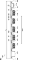
- FIG. 1 is a perspective view schematically showing an example of the electronic component series of the present invention.
- FIG. 2 is a sectional view taken along line II-II of the electronic component chain shown in FIG.
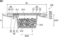
- FIG. 3 is a sectional view taken along line III-III of the electronic component chain shown in FIG.
- FIG. 4 is an enlarged cross-sectional view of the portion shown by IV in FIG.
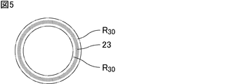
- FIG. 5 is a plan view of a part of the electronic component series shown in FIG. 3 as viewed from the height direction.
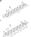
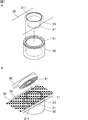
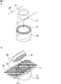
- 6A and 6B are perspective views schematically showing the main body of the electronic component storage container constituting the electronic component chain shown in FIG. 1.
- 7A and 7B are perspective views schematically showing an example of a step of detachably joining the cover sheet to the main body portion.
- FIG. 8A and 8B are plan views schematically showing an example of a step of detachably joining the cover sheet to the main body portion.
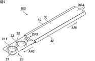
- FIG. 9 is a perspective view schematically showing how the lid portion of the electronic component series shown in FIG. 1 is slid and moved relative to the main body portion.
- FIG. 10 is a cross-sectional view schematically showing a state in which an electronic component is taken out from the electronic component series shown in FIG. 11A and 11B are perspective views schematically showing another example of a step of detachably joining the cover sheet to the main body portion.
- 12A and 12B are plan views schematically showing another example of a step of detachably joining the cover sheet to the main body portion.
- the present invention is not limited to the following embodiments, and can be appropriately modified and applied without changing the gist of the present invention. It should be noted that a combination of two or more of the individual preferable configurations described below is also the present invention.
- the electronic component chain of the present invention includes an electronic component storage container and electronic components stored in the electronic component storage container.
- the electronic component storage container constituting the electronic component chain of the present invention is also one of the present inventions.
- FIG. 1 is a perspective view schematically showing an example of the electronic component series of the present invention.
- FIG. 2 is a sectional view taken along line II-II of the electronic component chain shown in FIG.
- FIG. 3 is a sectional view taken along line III-III of the electronic component chain shown in FIG.
- the electronic component series 100 shown in FIGS. 1, 2 and 3 includes an electronic component storage container 10 and a plurality of electronic components 1 (see FIGS. 2 and 3) housed in the electronic component storage container 10.
- the electronic component storage container 10 includes a main body portion 20, a cover sheet 30, and a lid portion 40.
- the electronic component storage container 10 has, for example, a longitudinal direction (DR1 direction) and a width direction (DR2 direction), and is formed in a long shape.
- the longitudinal direction is a direction parallel to the slide direction (AR1 direction in FIG. 9) described later, and the width direction is a direction orthogonal to the longitudinal direction.
- the main body portion 20, the cover sheet 30, and the lid portion 40 When viewed in a plan view from the height direction (DR3 direction), have, for example, a rectangular shape.
- the height direction is a direction orthogonal to the longitudinal direction and the width direction.
- the main body 20 is provided so as to extend in the longitudinal direction.
- the main body 20 has a plurality of storage recesses 21 for storing the electronic component 1.
- the main body 20 has seven storage recesses 21.
- the storage recess 21 is arranged along the longitudinal direction.
- the seven storage recesses 21 are arranged side by side in a row along the longitudinal direction.
- the seven storage recesses 21A, 21B, 21C, 21D, 21E, 21F and 21G are arranged at the first end 20a of the main body 20 in the longitudinal direction.
- the area and depth of the opening of the storage recess 21A are smaller than those of the other storage recesses 21B, 21C, 21D, 21E, 21F and 21G.
- the storage recesses 21G arranged at the second end 20b of the main body 20 in the longitudinal direction have storage recesses 21B, 21C, 21D, 21E and 21F whose opening areas and depth dimensions are other than the storage recesses 21A. Is the same as.
- each storage recess 21 has an opening 211 on one side in the height direction.
- the opening 211 has, for example, a substantially circular shape.
- the main body 20 is formed, for example, by processing a sheet member.
- the material constituting the main body 20 include polystyrene and polyethylene terephthalate in which a conductive material such as carbon or a conductive paint is kneaded.
- the thickness of the main body 20 is, for example, about 0.5 mm.
- the cover sheet 30 is arranged so as to cover the opening 211 of the storage recess 21.
- the cover sheet 30 is detachably joined to at least a part of the main body 20.
- the cover sheet 30 has a strip shape. In the longitudinal direction, the cover sheet 30 is longer than the lid 40. Preferably, the length of the cover sheet 30 is at least twice the length of the main body 20.
- cover sheet 30 examples include polyethylene terephthalate, polycarbonate, acrylic and vinyl chloride. Further, the cover sheet 30 may be coated with a metal. The total thickness of the cover sheet 30 is, for example, about 50 ⁇ m.
- the cover sheet 30 is preferably composed of a plurality of layers.
- the cover sheet 30 includes, for example, a base material layer and an adhesive layer, and the adhesive layer is detachably bonded to the main body portion 20.
- the cover sheet 30 may include an intermediate layer or the like between the base material layer and the adhesive layer.
- a commercially available cover tape having antistatic performance can be used as the cover sheet 30 composed of a plurality of layers.
- the lid portion 40 is arranged so as to sandwich a part of the cover sheet 30 with the main body portion 20.
- the lid portion 40 is slidably fitted to the main body portion 20 in the longitudinal direction.
- the lid portion 40 is longer than the main body portion 20.
- the length of the lid 40 is less than half the length of the cover sheet 30.
- a plurality of electronic components 1 are stored in the storage recess 21 of the electronic component storage container 10.
- the electronic component series 100 is configured so that the electronic component 1 stored in the storage recess 21 can be taken out by sliding the lid portion 40 with respect to the main body portion 20 in the longitudinal direction.
- the electronic component 1 is, for example, a monolithic ceramic capacitor.
- the size of the electronic component 1 is not limited, and examples thereof include 1005 size, 0603 size, and 0402 size.
- the dimension in the longitudinal direction (L dimension) is 1.0 mm
- the dimension in the width direction (W dimension) is 0.5 mm
- the dimension in the thickness direction (T dimension) is not defined by the JIS standard, but is, for example, 0.5 mm.
- the L dimension, the W dimension, and the T dimension are all design target values, and are not necessarily exactly 1.0 mm, 0.5 mm, and 0.5 mm. That is, the L dimension, the W dimension, and the T dimension all have tolerances.
- the electronic component 1 which is a regular product is housed in the five storage recesses 21B, 21C, 21D, 21E and 21F excluding the storage recesses 21A and 21G at both ends.
- a small amount of electronic components 1 are stored in the storage recess 21A arranged at the first end 20a of the main body 20 for inspection.
- the electronic component 1 is not stored in the storage recess 21G arranged at the second end 20b of the main body 20.
- the electronic component 1 which is a regular product may be stored in the storage recess 21G.
- the storage recess 21A is not used for inspection, the electronic component 1 may not be stored in the storage recess 21A.
- the "storage recess 21" is a storage recess in which a genuine electronic component 1 is stored (in FIG. 2, the storage recesses 21B, 21C, 21D, 21E and 21F). Shall mean.
- the main body portion 20 is arranged around the opening 211 in the direction opposite to the depth direction (downward in FIG. 3) of the storage recess 21 (upper in FIG. 3). It has a raised portion 23 that rises toward it, and the cover sheet 30 is in contact with the raised portion 23 so as to follow the shape of the raised portion 23, and is detachably joined to the raised portion 23.
- the cover sheet 30 By providing a raised portion 23 around the opening 211 of the main body 20 and bringing the cover sheet 30 into contact with the shape of the raised portion 23, the cover sheet 30 can be uniformly adhered to the periphery of the opening 211. it can. As a result, the adhesive strength of the cover sheet 30 to the main body 20 can be made uniform around the opening 211.
- FIG. 4 is an enlarged cross-sectional view of the portion shown by IV in FIG.
- the raised portion 23 is preferably recessed into the cover sheet 30.
- the thickness T 1 of the cover sheet 30 in the portion where the raised portion 23 is recessed is smaller than the thickness T 2 of the cover sheet 30 in the portion not joined to the main body portion 20.
- the cover sheet 30 preferably has a region R 30 that protrudes in the depth direction of the storage recess 21 around the raised portion 23.
- the adhesive strength of the cover sheet 30 to the main body portion 20 can be increased.
- FIG. 5 is a plan view of a part of the electronic component series shown in FIG. 3 as viewed from the height direction. Note that FIG. 5 is a plan view of a portion on the main body side of the joint surface between the raised portion of the main body and the cover sheet as viewed from the height direction. As shown in FIG. 5, it is preferable that the entire inner circumference and outer circumference of the raised portion 23 have a region R 30 projecting in the depth direction of the storage recess 21.
- the cover sheet 30 is separated from the main body portion 20 of the portion not joined to the cover sheet 30 by 0.5 mm or more in the depth direction of the storage recess 21. That is, when the distance (the length indicated by X in FIG. 4) between the main body 20 and the cover sheet 30 of the portion not joined to the cover sheet 30 in the depth direction of the storage recess 21 is 0.5 mm or more. It is preferable to have. In this case, the cover sheet 30 can be stably peeled off from the main body 20.
- the distance X between the main body 20 and the cover sheet 30 in the portion not joined to the cover sheet 30 in the depth direction of the storage recess 21 is preferably 2 mm or less.
- the radius of curvature of the raised portion 23 is preferably 1.05 mm or more and 1.50 mm or less.
- the cover sheet 30 can be easily adhered uniformly to the raised portion 23. Further, the state in which the extremely small electronic component 1 having a size of 0603 or less is sandwiched between the adhesive portions is reduced, and it is possible to prevent the electronic component 1 from popping out when the cover sheet 30 is opened.
- the radius of curvature of the raised portion 23 is measured by the following method. First, the surface of the main body 20 is scanned by using a surface height measuring device using a laser, and mapping information in the height direction is acquired. For one storage recess 21, the radius of curvature of the two raised portions 23 in the cross section passing through the center of the opening 211 is measured. The radius of curvature of the raised portion 23 is measured at two locations for all the storage recesses 21 in which the electronic component 1 which is a regular product is stored, and the average value thereof is taken as the radius of curvature of the raised portion 23.
- the cross section passing through the center of the opening 211 may be any cross section as long as the cross section excluding the cross section along the line II-II of FIG. 1 in which the openings 211 are adjacent to each other. For example, a cross section along lines III-III of FIG. 1 can be mentioned. Further, the position of the cross section passing through the center of the opening 211 may be different for each storage recess 21.
- the main body portion 20 includes a storage recess 21, a strip portion 22, and a raised portion 23.
- the plurality of storage recesses 21 are arranged along the longitudinal direction, they may be arranged side by side in one row, may be arranged side by side in two rows, or may be arranged side by side in three or more rows. You may be. Further, the plurality of storage recesses 21 may be arranged in a matrix, in a staggered manner, or may be randomly arranged.
- the storage recess 21A arranged at the first end 20a of the main body 20 in the longitudinal direction has at least one of the opening area and depth dimension as compared with the other storage recesses. It is preferably a small directional identification storage recess.
- the storage recess 21A arranged at the first end 20a of the main body 20 in the longitudinal direction is for inspection in which the number of stored electronic components is smaller than that of other storage recesses. It is preferably a storage recess. In this case, it is possible to inspect before use by individually taking out only the electronic parts for inspection while maintaining the sealed state of the storage recess in which the genuine product is stored. Examples of the inspection before use include quality inspection such as electrical characteristics, inspection regarding the difference between the product label description information and the actual product of the packaged product.
- the storage recess 21A may also serve as a direction identification storage recess and an inspection storage recess.
- the storage recess 21 includes a bottom portion 212 and a peripheral wall portion 213, and an opening 211 is formed at a position facing the bottom portion 212.
- the bottom portion 212 is provided so as to be substantially parallel to the strip portion 22.
- the peripheral wall portion 213 is erected from the peripheral edge of the bottom portion 212.
- An opening 211 is provided on the end side of the peripheral wall portion 213 connected to the strip portion 22.
- the opening 211 of the storage recess 21 When viewed in a plan view from the height direction, the opening 211 of the storage recess 21 preferably has a shape that does not include a side portion extending in a direction orthogonal to the relative sliding direction of the lid portion 40 described later.
- the opening 211 preferably has a substantially circular shape or an elliptical shape when viewed in a plan view.
- the opening 211 may have a polygonal shape such as a rhombus in which a pair of vertices are arranged in the longitudinal direction and another pair of vertices are arranged in the width direction when viewed in a plan view.
- the opening 211 has such a shape, when the lid 40 is slid with respect to the main body 20, the cover sheet 30 and the main body 20 of the portion located around the opening 211 are joined. The area changes gently along the peeling direction. As a result, when the cover sheet 30 is peeled off, a large force momentarily acts on the joint portion 33 (see FIG. 3) of the cover sheet 30 to tear the cover sheet 30 or make the cover sheet 30 inseparable. It is possible to prevent the cover.
- the storage recess 21 is made of resin.
- the surface resistivity of the inner surface of the storage recess 21 is preferably, for example, 0 ⁇ / ⁇ or more and 1 ⁇ 10 9 ⁇ / ⁇ or less. As a result, it is possible to prevent the electronic component 1 from adhering to the inner surface of the storage recess 21 due to static electricity.
- the strip portion 22 is configured to fit into the guide portion 42 of the lid portion 40, which will be described later. By fitting the strip portion 22 of the main body portion 20 to the guide portion 42 of the lid portion 40, the main body portion 20 is held by the lid portion 40 in the height direction.
- the strip portion 22 has a front surface 22a and a back surface 22b.
- the strip portion 22 is provided so as to be substantially parallel to the opening surface 214 of the storage recess 21.
- the raised portion 23 is provided at the opening end of the opening portion 211.
- the raised portion 23 may be provided on the main body portion 20 of a portion located around the storage recess 21.
- the raised portion 23 is raised toward the direction opposite to the depth direction (downward in FIG. 3) of the storage recess 21 (upward in FIG. 3).
- the raised portion 23 is provided so as to surround the opening 211.
- the raised portion 23 has substantially the same shape as the peripheral portion defining the opening 211 when viewed in a plan view from the height direction.
- the opening edge of the storage recess 21 adjacent to the opening 211 preferably has a curved portion.
- the raised portion 23 preferably has a curved portion on the opening 211 side that curves along the depth direction of the storage recess 21 toward the bottom 212 of the storage recess 21.
- the height of the raised portion 23 is, for example, 0.5 mm or more and 1.2 mm or less. By setting the raised portion 23 to the above height, it is possible to prevent the electronic component 1 and the like from being sandwiched between the lid portion 40 and the strip portion 22.
- the width of the raised portion 23 is, for example, about 1 mm or more and 2 mm or less. By setting the raised portion 23 to the above width, the force required for peeling the cover sheet 30 from the raised portion 23 can be reduced. As a result, deformation of the lid portion 40 and the main body portion 20 can be suppressed, and the cover sheet 30 can be stably peeled off from the raised portion 23.
- FIG. 6A and 6B are perspective views schematically showing the main body of the electronic component storage container constituting the electronic component chain shown in FIG. 1.
- Longitudinal dimension of the main body 20 (in FIG. 6A, the length indicated by L 2) is, for example, 168 mm ⁇ 1 mm.
- the width dimension of the main body portion 20 (in FIG. 6A, the length indicated by W 2) is, for example, 32 mm ⁇ 0.3 mm.
- the outer diameter of the housing recess 21 except for the housing recess 21A is, for example, 19 mm ⁇ 0.2 mm.
- Depth of the receiving recess 21 except for the housing recess 21A is, for example, 12.5 mm ⁇ 0.5 mm.
- the outer diameter of the housing recess 21A (in FIG. 6B, the length indicated by D 2) is, for example, 15 mm ⁇ 0.2 mm. Depth of the receiving recess 21A (in FIG. 6B, the length indicated by d 2) is, for example, 5.5 mm ⁇ 0.5 mm.
- the storage recess 21A preferably has an outer diameter of 80% or less, a depth dimension of 50% or less, and a volume of 30% or less, as compared with other storage recesses 21.
- the pitch of the housing recess 21 includes a receiving recess 21A (in FIG. 6B, the length indicated by P 1) is, for example, 24.0 mm ⁇ 0.1 mm.
- the pitch of the storage recesses means the distance between the center points of the adjacent storage recesses.
- the cover sheet 30 is wound and held around the lid 40. Specifically, it is preferable that the cover sheet 30 is wound around the lid 40 around an axis whose winding axis is in the width direction. As a result, the cover sheet 30 includes a portion 31 located on the front surface 40a side of the lid portion 40 and a portion 32 located on the back surface 40b side of the lid portion 40 (see FIG. 3).
- the first end portion 30a and the second end portion 30b of the cover sheet 30 are connected by, for example, an adhesive tape 35. Specifically, the first end portion 30a side and the second end portion 30b side of the cover sheet 30 are connected in an overlapping state.
- the cover sheet 30 is wound around the lid portion 40 after being joined to each of the plurality of raised portions 23. After that, both ends of the cover sheet 30 are connected. As long as both ends of the cover sheet 30 are connected, the connection method is not limited to the connection by the adhesive tape as described above.
- the cover sheet 30 is wound around the lid 40 so as to orbit around the lid 40 in conjunction with the relative sliding movement of the lid 40.
- the cover sheet 30 rotates around the lid 40 as shown in the DR4 direction in FIG. ..
- the cover sheet 30 is detachably joined to at least a part of the main body portion 20.
- the cover sheet 30 has a joint portion 33 joined to at least a part of the main body portion 20 of a portion located around each of the plurality of openings 211 (see FIG. 3).
- the adhesive strength of the cover sheet is measured by, for example, a measuring method defined in JIS C0806-3 (P21) according to the peel strength test of the cover tape of the taping packaging part.
- the cover sheet 30 is made of, for example, a heat-weldable material.
- the cover sheet 30 is joined to the main body portion 20, more specifically, to each of the plurality of raised portions 23 by heat welding.
- the adhesiveness of the cover sheet 30 and the raised portion 23 at the joint portion 33 is small in order to prevent the electronic component 1 from adhering to the peeled portion of the cover sheet 30. Is preferable.
- the cover sheet 30 may be joined to the main body portion 20, more specifically, the raised portion 23 by an adhesive.
- the cover sheet 30 is preferably transparent, but may not be transparent.
- the surface resistivity of the cover sheet 30 is preferably 1 ⁇ 10 11 ⁇ / ⁇ or less. As a result, it is possible to prevent the electronic component 1 from adhering to the surface of the cover sheet 30 due to static electricity.
- the lid 40 is arranged so as to sandwich a part of the cover sheet 30 between the main body 20 and, more specifically, the raised portion 23. Has been done. It is preferable that the surface of the lid portion 40 facing the main body portion 20 is neither fixed nor joined to the cover sheet 30.
- the lid portion 40 includes the plate-shaped portion 41 and the guide portion 42, and is slidably fitted to the main body portion 20 in the longitudinal direction.
- the plate-shaped portion 41 extends along the longitudinal direction.
- the plate-shaped portion 41 is provided so as to be substantially parallel to the strip portion 22.
- the cover sheet 30 is wound around the plate-shaped portion 41.
- the guide portions 42 are provided at both ends of the plate-shaped portion 41 in the width direction.
- the guide portion 42 guides the sliding movement of the lid portion 40 with respect to the main body portion 20 while preventing the lid portion 40 from falling off from the main body portion 20.
- the guide portion 42 has a strip portion so that the strip portion 22 is located between a portion of the strip portion 22 facing the front surface 22a and a portion of the strip portion 22 facing the back surface 22b. It is arranged at the end of 22 with a gap.
- the shape of the guide portion 42 can be appropriately changed as long as the lid portion 40 can slide and move relative to the main body portion 20.
- the lid portion 40 is formed by, for example, a molding process such as vacuum forming or injection molding. Examples of the material constituting the lid portion 40 include resin and the like.
- the lid 40 may or may not be transparent. When the lid portion 40 and the cover sheet 30 are made transparent, it can be visually confirmed that a plurality of electronic components 1 are housed in the storage recess 21.
- the lid portion 40 is preferably longer than the main body portion 20. In the longitudinal direction, the length of the lid 40 is preferably less than half the length of the cover sheet 30.
- Electronic longitudinal dimension of the component storage container 10 is, for example, 169 mm ⁇ 1 mm.
- the length indicated by W 1 Electronic widthwise dimension of the component storage container 10 is, for example, 35.8mm ⁇ 1mm.
- the length indicated by H 1 Electronic height dimension of the component container 10 is, for example, 13.7 mm.
- the height of the fitting portion of the main body portion 20 and the lid 40 (in FIG. 3, the length indicated by H 2) is, for example, 2 mm ⁇ 0.2 mm.
- the required number of electronic components 1 are stored in the predetermined storage recess 21 of the main body 20.
- the cover sheet 30 is detachably joined to the main body 20 so as to cover the opening 211 of each storage recess 21.
- the cover sheet 30 is heat-welded to the raised portion 23 and joined.
- the cover sheet 30 is arranged on the main body 20 along the longitudinal direction so that the cover sheet 30 protrudes from both ends in the longitudinal direction.
- FIGS. 8A and 8B are perspective views schematically showing an example of a process of detachably joining the cover sheet to the main body portion.
- 8A and 8B are plan views schematically showing an example of a step of detachably joining the cover sheet to the main body portion.
- the main body 20 and the support member 50 are shown in cross-sectional view.
- the periphery of the storage recess 21 of the main body 20 is supported by a support member 50 such as a trowel receiver from the direction in which the storage recess 21 is held. At this time, it is preferable to move the main body 20 along the longitudinal direction so that the target storage recess 21 is set at a predetermined position. As described above, the main body 20 has a raised portion 23 around the opening 211.
- the support member 50 has, for example, a cup shape as a whole and a ring shape on the upper surface serving as a contact surface with the main body portion 20.
- the opening of the support member 50 is preferably larger than the opening 211 of the storage recess 21.
- the support member 50 preferably has an elastic portion 51.
- the material constituting the elastic portion 51 include rubber materials such as urethane rubber and silicone rubber.
- the material constituting the support member 50 other than the elastic portion 51 is preferably a material having a Young's modulus (E / GPa) of 60 or more and 220 or less, and examples thereof include stainless steel (SUS), aluminum, and steel.
- the elastic portion 51 of the support member 50 is brought into contact with the main body portion 20 as shown in FIGS. 7A and 8A.
- a pressing jig 60 such as a trowel is used on the raised portion 23 in the depth direction of the storage recess 21.
- the cover sheet 30 is pressed toward it. As a result, the cover sheet 30 can be heat-welded to the raised portion 23.
- the pressing jig 60 preferably has a ring-shaped contact portion 61 in a plan view seen from the adhesive surface side.
- the width of the contact portion 61 is preferably larger than the width of the raised portion 23.
- the raised portion 23 is provided around the opening 211 of the main body portion 20, the area where the cover sheet 30 is adhered to the main body portion 20 is physically restricted. Therefore, the height of the main body 20 varies due to the variation in molding, the pressing jig 60 is tilted with respect to the adhesive surface, or the main body 20 is displaced with respect to the fixed position of the support member 50. Even in the case of being supported, the adhesive strength of the cover sheet 30 to the main body 20 can be made uniform around the opening 211.
- the support member 50 has the elastic portion 51, the pressure distribution when the pressing jig 60 descends can be made uniform. Therefore, it is possible to reduce the influence when the height of the main body portion 20 varies due to the variation in molding or the pressing jig 60 is tilted with respect to the adhesive surface.
- the main body 20 After joining the cover sheet 30 to one storage recess 21, the main body 20 is moved along the longitudinal direction so that the support member 50 is lowered and the next storage recess 21 is set. These are repeated to join the cover sheet 30 to all the storage recesses 21.
- the predetermined length is, for example, a length at which the lid portion 40 can be wound around the cover sheet 30.
- the lid portion 40 is arranged so as to sandwich the cover sheet 30 located on the main body portion 20 with the main body portion 20.
- the cover sheet 30 of the portion protruding from both ends of the main body 20 is wound around the lid 40, and both ends of the cover sheet 30 are joined to each other.
- the electronic component series 100 in which the plurality of electronic components 1 are sealed in the plurality of storage recesses 21 is manufactured.
- FIG. 9 is a perspective view schematically showing how the lid portion of the electronic component series shown in FIG. 1 is slid and moved relative to the main body portion.
- FIG. 10 is a cross-sectional view schematically showing a state in which an electronic component is taken out from the electronic component series shown in FIG.
- FIG. 9 shows a state in which the electronic component series 100 is arranged so that the opening 211 of the storage recess 21 faces upward for convenience.
- the electronic component 1 it is shown in FIG.
- a state in which the electronic component 1 is taken out from the electronic component series 100 according to the present embodiment will be described with reference to FIGS. 9 and 10.
- the lid 40 in order to take out the plurality of electronic components 1 stored in the storage recess 21, the lid 40 is relatively along the sliding direction (AR1 direction) with respect to the main body 20. Move the slide. Specifically, the lid portion 40 is fixed by a fixing device (not shown), and the main body portion 20 is slid and moved in the direction opposite to the AR1 direction (AR2 direction). The main body 20 is moved by a predetermined amount by a transport device (not shown).
- the transport device may be of a conveyor type in which the main body 20 is placed and moved, or may be configured to grip and move the main body 20.
- the directionality can be identified by the appearance, so that the risk of erroneous attachment to equipment such as a fixing device is reduced. As a result, the risk of erroneous peeling direction of the cover sheet 30 is also reduced.
- the cover sheet 30 rotates around the lid 40 as shown in the DR4 direction in conjunction with the relative sliding movement of the lid 40.
- the portion 32 located on the back surface 40b side of the lid portion 40 moves to the front surface 40a side of the lid portion 40
- the lid portion 40 On the front side in the relative sliding direction of the lid portion 40, the portion 31 located on the front surface 40a side of the lid portion 40 is rotated around the winding axis so as to move to the back surface 40b side of the lid portion 40.
- the cover sheet 30 When focusing on one storage recess 21, the cover sheet 30 is peeled off from the periphery (raised portion 23) of the opening 211 from one end side to the other end side in the relative sliding direction of the lid portion 40.
- the storage recess 21 is opened.
- the plurality of electronic components 1 fall downward from the opening 211 and are supplied to the supplied portion.
- the inner peripheral surface of the storage recess 21 is formed smoothly without having a groove or the like. As a result, it is possible to prevent the plurality of electronic components 1 from being caught on the inner peripheral surface of the storage recess 21, and the plurality of electronic components 1 can be smoothly taken out from the electronic component storage container 10.
- the cover portion 40 slides relatively in the AR1 direction from the second end portion 20b side of the main body portion 20 toward the first end portion 20a side, so that the lid portion 40 slides toward the second end portion 20b side of the main body portion 20.
- the cover sheet 30 is peeled off from the raised portion 23 toward the first end portion 20a side, and the storage recess 21 is opened in order. As a result, the plurality of electronic components 1 are sequentially taken out from the opened storage recess 21.
- the relative sliding movement of the lid portion 40 may be performed continuously or intermittently.
- a plurality of electronic components 1 can be smoothly taken out from the electronic component storage container 10.
- the surface of the lid 40 facing the main body 20 is not joined to the cover sheet 30, so that the lid 40 is slid relative to the main body 20.
- the lid 40 can be moved smoothly.
- the cover sheet 30 can be moved with respect to the lid portion 40, and the cover sheet 30 can be easily peeled off from the main body portion 20.
- the storage recess 21 is opened by using the fixing device and the transport device. Can be done automatically. This makes it possible to automatically supply a plurality of electronic components 1 to the supplied unit.
- the cover sheet 30 is held by the lid portion 40, and the lid portion 40 is configured to be slidable relative to the main body portion 20 along the direction parallel to the opening surface of the storage recess 21. It is possible to prevent the lid portion 40 and the main body portion 20 from being deformed when the sheet 30 is peeled off.
- the electronic component storage container and the electronic component chain of the present invention are not limited to the above-described embodiment, and various applications and modifications are added within the scope of the present invention regarding the configuration, manufacturing conditions, etc. of the electronic component storage container. It is possible.
- identification labels may be affixed to the upper surface and the lower surface of the electronic component storage container 10, respectively.
- the first identification label may be attached to the lid 40 of the electronic component storage container 10, and the second identification label may be attached to the main body 20 of the electronic component storage container 10.
- the first identification label may be affixed between the cover sheet 30 and the lid portion 40, or may be affixed to the upper surface of the cover sheet 30.
- the first identification label includes, for example, the same bar code information as the two-dimensional code information described in the second identification label.
- the first identification label includes, for example, a product identification code, a part identification code, a quantity code, a traceability code, and the like as barcode information.
- the first identification label may further include readable information written in characters. For more information, see IEC 62090: 2017 (Product package labels for electronic components using bar code and two-dimensional systems).
- the second identification label is, for example, the back surface of the storage recess 21 arranged at the position closest to the second end 20b of the main body 20 among the storage recesses 21 in which the electronic component 1 which is a genuine product is stored. It is affixed to.
- the second identification label includes, for example, only the same two-dimensional code as the bar code information of the first identification label.
- the lid 40 is fixed and the main body 20 is slidably moved has been described, but the main body 20 may be fixed and the lid 40 may be slid.
- the lid portion 40 is fixed and the main body portion 20 is slidably moved, a plurality of electronic components 1 can be stably supplied to the supplied portion without moving the installation position of the supplied portion.
- the guide portion 42 is provided on the lid portion 40
- the guide portion may be provided on the main body portion 20.
- the lid portion 40 is formed in a flat plate shape, and guide portions are formed on both ends of the strip portion 22 in the main body portion 20 in the width direction.
- the guide portion is configured to straddle the end surface of the lid portion 40 and be bent from the back surface 40b of the lid portion 40 to the front surface 40a of the lid portion 40.
- the periphery of the storage recess of the main body portion may be supported by a support member having an elastic portion.
- 11A and 11B are perspective views schematically showing another example of a step of detachably joining the cover sheet to the main body portion.
- 12A and 12B are plan views schematically showing another example of a step of detachably joining the cover sheet to the main body portion.
- the main body 20'and the support member 50 are shown in cross-sectional view.
- the periphery of the storage recess 21 of the main body 20' is supported by the support member 50 having the elastic portion 51 from the direction of having the storage recess 21.
- the main body 20'does not have a raised portion 23 around the opening 211.
- the elastic portion 51 of the support member 50 is brought into contact with the main body portion 20'.
- a pressing jig 60 is used around the opening 211 in the depth direction of the storage recess 21.
- the cover sheet 30 is pressed toward it. As a result, the cover sheet 30 can be heat-welded around the opening 211.
- the support member 50 has the elastic portion 51, so that the pressure distribution when the pressing jig 60 descends can be made uniform. .. Therefore, it is possible to reduce the influence when the height of the main body portion 20 varies due to the variation in molding or the pressing jig 60 is tilted with respect to the adhesive surface.
- the inner peripheral surface of the storage recess that defines the opening is curved at the opening edge along the depth direction of the storage recess towards the bottom of the storage recess. It is preferable to have a curved portion.
Abstract
Description
しかしながら、本発明は、以下の実施形態に限定されるものではなく、本発明の要旨を変更しない範囲において適宜変更して適用することができる。なお、以下において記載する個々の好ましい構成を2つ以上組み合わせたものもまた本発明である。 Hereinafter, the electronic component storage container and the electronic component chain of the present invention will be described.
However, the present invention is not limited to the following embodiments, and can be appropriately modified and applied without changing the gist of the present invention. It should be noted that a combination of two or more of the individual preferable configurations described below is also the present invention.
図1は、本発明の電子部品連の一例を模式的に示す斜視図である。図2は、図1に示す電子部品連のII-II線断面図である。図3は、図1に示す電子部品連のIII-III線断面図である。 [Electronic components]
FIG. 1 is a perspective view schematically showing an example of the electronic component series of the present invention. FIG. 2 is a sectional view taken along line II-II of the electronic component chain shown in FIG. FIG. 3 is a sectional view taken along line III-III of the electronic component chain shown in FIG.
図4に示すように、隆起部23は、カバーシート30にめり込んでいることが好ましい。この場合、隆起部23がめり込んでいる部分のカバーシート30の厚さT1は、本体部20と接合されていない部分のカバーシート30の厚さT2よりも小さいことが好ましい。 FIG. 4 is an enlarged cross-sectional view of the portion shown by IV in FIG.
As shown in FIG. 4, the raised
図5に示すように、隆起部23の内周および外周の全体に、収納凹部21の深さ方向に向けて突出する領域R30を有することが好ましい。 FIG. 5 is a plan view of a part of the electronic component series shown in FIG. 3 as viewed from the height direction. Note that FIG. 5 is a plan view of a portion on the main body side of the joint surface between the raised portion of the main body and the cover sheet as viewed from the height direction.
As shown in FIG. 5, it is preferable that the entire inner circumference and outer circumference of the raised
本実施形態では、図3に示すように、本体部20は、収納凹部21、ストリップ部22および隆起部23を備える。 (Main body)
In the present embodiment, as shown in FIG. 3, the
長手方向における本体部の一方の端部にのみサイズの異なる収納凹部を設けることにより、外観上、方向性を識別可能な状態にすることができる。これにより、後述する固定装置などの設備へ取り付ける方向またはカバーシートを剥離する方向などを誤るリスクを低減することができる。 Of the plurality of storage recesses 21, the
By providing storage recesses having different sizes only at one end of the main body in the longitudinal direction, it is possible to make the directionality identifiable in appearance. As a result, it is possible to reduce the risk of erroneous attachment to equipment such as a fixing device described later or the direction of peeling the cover sheet.
この場合、正規製品が収納されている収納凹部の密閉状態を維持した状態で、検品用の電子部品のみを個別に取り出すことにより、使用前の検査が可能となる。使用前の検査としては、例えば、電気的特性などの品質検査、製品ラベル記載情報と包装製品の現品相違に関する検査などが挙げられる。 Of the plurality of storage recesses 21, the
In this case, it is possible to inspect before use by individually taking out only the electronic parts for inspection while maintaining the sealed state of the storage recess in which the genuine product is stored. Examples of the inspection before use include quality inspection such as electrical characteristics, inspection regarding the difference between the product label description information and the actual product of the packaged product.
本体部20の長手方向の寸法(図6A中、L2で示す長さ)は、例えば、168mm±1mmである。本体部20の幅方向の寸法(図6A中、W2で示す長さ)は、例えば、32mm±0.3mmである。 6A and 6B are perspective views schematically showing the main body of the electronic component storage container constituting the electronic component chain shown in FIG. 1.
Longitudinal dimension of the main body 20 (in FIG. 6A, the length indicated by L 2) is, for example, 168 mm ± 1 mm. The width dimension of the main body portion 20 (in FIG. 6A, the length indicated by W 2) is, for example, 32 mm ± 0.3 mm.
なお、収納凹部のピッチとは、隣り合う収納凹部の中心点間の距離を意味する。 The pitch of the
The pitch of the storage recesses means the distance between the center points of the adjacent storage recesses.
本実施形態では、図1、図2および図3に示すように、カバーシート30は、蓋部40に巻回されて保持されている。具体的には、カバーシート30は、幅方向を巻回軸とする軸回りに蓋部40に巻回されていることが好ましい。これにより、カバーシート30は、蓋部40のおもて面40a側に位置する部分31と、蓋部40のうら面40b側に位置する部分32とを含む(図3参照)。 (Cover sheet)
In the present embodiment, as shown in FIGS. 1, 2 and 3, the
なお、カバーシートの接着強度は、例えば、JIS C0806-3(P21)で定義する、テーピング包装部品のカバーテープの剥離強度試験に準じた測定方法により測定される。 The adhesive strength of the
The adhesive strength of the cover sheet is measured by, for example, a measuring method defined in JIS C0806-3 (P21) according to the peel strength test of the cover tape of the taping packaging part.
本実施形態では、図1、図2および図3に示すように、蓋部40は、本体部20、より特定的には隆起部23との間にカバーシート30の一部を挟み込むように配置されている。蓋部40における本体部20と対向する面は、カバーシート30と固定も接合もされていないことが好ましい。 (Cover)
In the present embodiment, as shown in FIGS. 1, 2 and 3, the
ガイド部42は、本体部20から蓋部40が脱落することを防止しつつ、本体部20に対する蓋部40のスライド移動を案内する。具体的には、ガイド部42は、ストリップ部22のおもて面22aに対向する部分とストリップ部22のうら面22bに対向する部分との間にストリップ部22が位置するように、ストリップ部22の端部に隙間を隔てて配置されている。 The
The
本発明の電子部品連の製造方法の一例として、図1に示す電子部品連100の製造方法について説明する。 [Manufacturing method of electronic component series]
As an example of the manufacturing method of the electronic component series of the present invention, the manufacturing method of the
図9は、図1に示す電子部品連の蓋部を本体部に対して相対的にスライド移動させる様子を模式的に示す斜視図である。図10は、図1に示す電子部品連から電子部品を取り出す様子を模式的に示す断面図である。なお、図9においては、便宜上、収納凹部21の開口部211が上方に向くように電子部品連100が配置された状態を示しているが、電子部品1を取り出す際には、図10に示すように、収納凹部21の開口部211が下方に向くように電子部品連100が配置された状態で、蓋部40を本体部20に対して相対的にスライド移動させることが好ましい。図9および図10を参照して、本実施形態に係る電子部品連100から電子部品1を取り出す様子を説明する。 [How to use the electronic component chain]
FIG. 9 is a perspective view schematically showing how the lid portion of the electronic component series shown in FIG. 1 is slid and moved relative to the main body portion. FIG. 10 is a cross-sectional view schematically showing a state in which an electronic component is taken out from the electronic component series shown in FIG. Note that FIG. 9 shows a state in which the
本発明の電子部品収納容器および電子部品連は、上記実施形態に限定されるものではなく、電子部品収納容器の構成、製造条件等に関し、本発明の範囲内において、種々の応用、変形を加えることが可能である。 [Other Embodiments]
The electronic component storage container and the electronic component chain of the present invention are not limited to the above-described embodiment, and various applications and modifications are added within the scope of the present invention regarding the configuration, manufacturing conditions, etc. of the electronic component storage container. It is possible.
詳細については、IEC 62090:2017(Product package labels for electronic components using bar code and two-dimensional symbologies)を参照されたい。 The first identification label includes, for example, the same bar code information as the two-dimensional code information described in the second identification label. The first identification label includes, for example, a product identification code, a part identification code, a quantity code, a traceability code, and the like as barcode information. The first identification label may further include readable information written in characters.
For more information, see IEC 62090: 2017 (Product package labels for electronic components using bar code and two-dimensional systems).
10 電子部品収納容器
20,20´ 本体部
20a 本体部の第1の端部
20b 本体部の第2の端部
21,21A,21B,21C,21D,21E,21F,21G 収納凹部
211 開口部
212 底部
213 周壁部
214 開口面
22 ストリップ部
22a ストリップ部のおもて面
22b ストリップ部のうら面
23 隆起部
30 カバーシート
30a カバーシートの第1の端部
30b カバーシートの第2の端部
31 蓋部のおもて面側に位置するカバーシート
32 蓋部のうら面側に位置するカバーシート
33 カバーシートの接合部
35 接着テープ
40 蓋部
40a 蓋部のおもて面
40b 蓋部のうら面
41 板状部
42 ガイド部
50 支持部材
51 弾性部
60 押圧治具
61 接触部
100 電子部品連
L1 電子部品収納容器の長手方向の寸法
L2 本体部の長手方向の寸法
W1 電子部品収納容器の幅方向の寸法
W2 本体部の幅方向の寸法
H1 電子部品収納容器の高さ方向の寸法
H2 本体部と蓋部との嵌合部の高さ
P1 収納凹部のピッチ
D1 収納凹部21Aを除く収納凹部21の外径
D2 収納凹部21Aの外径
d1 収納凹部21Aを除く収納凹部21の深さ寸法
d2 収納凹部21Aの深さ寸法
R30 収納凹部の深さ方向に向けて突出する領域
T1 隆起部がめり込んでいる部分のカバーシートの厚さ
T2 本体部と接合されていない部分のカバーシートの厚さ
X カバーシートと接合されていない部分の本体部とカバーシートとの間の距離 1 Electronic parts 10 Electronic parts storage container 20, 20'Main body 20a First end of main body 20b Second end of main body 21,21A, 21B, 21C, 21D, 21E, 21F, 21G Storage recess 211 Opening 212 Bottom 213 Peripheral wall 214 Opening surface 22 Strip part 22a Front surface of strip part 22b Back surface of strip part 23 Raised part 30 Cover sheet 30a First end of cover sheet 30b Second end of cover sheet Part 31 Cover sheet located on the front side of the lid 32 Cover sheet located on the back side of the lid 33 Joint of the cover sheet 35 Adhesive tape 40 Lid 40a Front surface of the lid 40b Lid Lid surface 41 Plate-shaped part 42 Guide part 50 Support member 51 Elastic part 60 Pressing jig 61 Contact part 100 Electronic parts connection L 1 Longitudinal dimensions of electronic parts storage container L 2 Longitudinal dimensions of main body W 1 Electronics Width direction of the parts storage container W 2 Width direction of the main body H 1 Height direction of the electronic parts storage container H 2 Height of the fitting part between the main body and the lid P 1 Pitch of the storage recess D 1 Outer diameter of the storage recess 21 excluding the storage recess 21A D 2 Outer diameter of the storage recess 21A d 1 Depth dimension of the storage recess 21 excluding the storage recess 21A d 2 Depth dimension of the storage recess 21A R 30 Depth of the storage recess 21A Area protruding in the longitudinal direction T 1 Thickness of the cover sheet where the raised part is recessed T 2 Thickness of the cover sheet where it is not joined to the main body X The main body of the part which is not joined to the cover sheet Distance between the part and the cover sheet
Claims (13)
- 電子部品を収納するための複数の収納凹部が長手方向に沿って配置され、それぞれの前記収納凹部が高さ方向の一方側に開口部を有する本体部と、
前記収納凹部の前記開口部を覆うように、前記本体部にカバーシートを剥離可能に接合されているカバーシートと、
前記本体部との間に前記カバーシートを挟み込むように配置される蓋部と、を備え、
前記本体部は、前記開口部の周囲に、前記収納凹部の深さ方向と反対側の方向に向けて隆起する隆起部を有し、
前記カバーシートは、前記隆起部の形状に沿うように接触し、かつ、前記隆起部に剥離可能に接合されている、電子部品収納容器。 A main body portion in which a plurality of storage recesses for storing electronic components are arranged along the longitudinal direction, and each of the storage recesses has an opening on one side in the height direction.
A cover sheet to which the cover sheet is detachably joined to the main body so as to cover the opening of the storage recess.
A lid portion arranged so as to sandwich the cover sheet with the main body portion is provided.
The main body portion has a raised portion that rises around the opening in a direction opposite to the depth direction of the storage recess.
An electronic component storage container in which the cover sheet is in contact with the raised portion so as to follow the shape of the raised portion and is detachably joined to the raised portion. - 前記隆起部の曲率半径は、1.05mm以上1.50mm以下である、請求項1に記載の電子部品収納容器。 The electronic component storage container according to claim 1, wherein the radius of curvature of the raised portion is 1.05 mm or more and 1.50 mm or less.
- 前記隆起部は、前記カバーシートにめり込んでいる、請求項1または2に記載の電子部品収納容器。 The electronic component storage container according to claim 1 or 2, wherein the raised portion is recessed in the cover sheet.
- 前記隆起部がめり込んでいる部分の前記カバーシートの厚さは、前記本体部と接合されていない部分の前記カバーシートの厚さよりも小さい、請求項3に記載の電子部品収納容器。 The electronic component storage container according to claim 3, wherein the thickness of the cover sheet in the portion where the raised portion is recessed is smaller than the thickness of the cover sheet in the portion not joined to the main body portion.
- 前記カバーシートは、前記隆起部の周囲に、前記収納凹部の深さ方向に向けて突出する領域を有する、請求項3または4に記載の電子部品収納容器。 The electronic component storage container according to claim 3 or 4, wherein the cover sheet has a region that protrudes in the depth direction of the storage recess around the raised portion.
- 前記カバーシートは、複数層から構成されている、請求項1~5のいずれか1項に記載の電子部品収納容器。 The electronic component storage container according to any one of claims 1 to 5, wherein the cover sheet is composed of a plurality of layers.
- 前記カバーシートは、前記収納凹部の深さ方向において、前記カバーシートと接合されていない部分の前記本体部と0.5mm以上離れている、請求項1~6のいずれか1項に記載の電子部品収納容器。 The electron according to any one of claims 1 to 6, wherein the cover sheet is separated from the main body portion of a portion not joined to the cover sheet by 0.5 mm or more in the depth direction of the storage recess. Parts storage container.
- 請求項1~7のいずれか1項に記載の電子部品収納容器と、
前記電子部品収納容器の収納凹部に収納された電子部品と、を備える、電子部品連。 The electronic component storage container according to any one of claims 1 to 7.
An electronic component chain including electronic components stored in a storage recess of the electronic component storage container. - 電子部品を収納するための複数の収納凹部が長手方向に沿って配置され、それぞれの前記収納凹部が高さ方向の一方側に開口部を有する本体部の、それぞれの前記収納凹部の前記開口部を覆うように、前記本体部にカバーシートを剥離可能に接合させる工程と、
前記本体部との間に前記カバーシートを挟み込むように蓋部を配置する工程と、を備える、電子部品収納容器の製造方法であって、
前記本体部は、前記開口部の周囲に、前記収納凹部の深さ方向と反対側の方向に向けて隆起する隆起部を有し、
前記本体部に前記カバーシートを剥離可能に接合させる工程は、
前記本体部の前記収納凹部の周囲を、前記収納凹部を有する方向から、支持部材によって支持する工程と、
前記支持部材によって前記本体部が支持された状態で、前記隆起部に、押圧治具を用いて、前記収納凹部の深さ方向に向かって、前記カバーシートを押圧する工程と、を備える、電子部品収納容器の製造方法。 A plurality of storage recesses for storing electronic components are arranged along the longitudinal direction, and the openings of the respective storage recesses of the main body portion in which each of the storage recesses has an opening on one side in the height direction. The process of joining the cover sheet to the main body so that it can be peeled off,
A method for manufacturing an electronic component storage container, comprising a step of arranging a lid portion so as to sandwich the cover sheet with the main body portion.
The main body portion has a raised portion that rises around the opening in a direction opposite to the depth direction of the storage recess.
The step of detachably joining the cover sheet to the main body is
A step of supporting the periphery of the storage recess of the main body by a support member from the direction of having the storage recess.
An electron including a step of pressing the cover sheet toward the depth direction of the storage recess by using a pressing jig on the raised portion in a state where the main body portion is supported by the supporting member. Manufacturing method of parts storage container. - 前記支持部材は、弾性部を有する、請求項9に記載の電子部品収納容器の製造方法。 The method for manufacturing an electronic component storage container according to claim 9, wherein the support member has an elastic portion.
- 電子部品を収納するための複数の収納凹部が長手方向に沿って配置され、それぞれの前記収納凹部が高さ方向の一方側に開口部を有する本体部の、それぞれの前記収納凹部の前記開口部を覆うように、前記本体部にカバーシートを剥離可能に接合させる工程と、
前記本体部との間に前記カバーシートを挟み込むように蓋部を配置する工程と、を備える、電子部品収納容器の製造方法であって、
前記本体部に前記カバーシートを剥離可能に接合させる工程は、
前記本体部の前記収納凹部の周囲を、前記収納凹部を有する方向から、弾性部を有する支持部材によって支持する工程と、
前記支持部材によって前記本体部が支持された状態で、前記開口部の周囲に、押圧治具を用いて、前記収納凹部の深さ方向に向かって、前記カバーシートを押圧する工程と、を備える、電子部品収納容器の製造方法。 A plurality of storage recesses for storing electronic components are arranged along the longitudinal direction, and the openings of the respective storage recesses of the main body portion in which each of the storage recesses has an opening on one side in the height direction. A step of detachably joining the cover sheet to the main body so as to cover the
A method for manufacturing an electronic component storage container, comprising a step of arranging a lid portion so as to sandwich the cover sheet with the main body portion.
The step of detachably joining the cover sheet to the main body is
A step of supporting the periphery of the storage recess of the main body portion by a support member having an elastic portion from the direction of having the storage recess.
A step of pressing the cover sheet in the depth direction of the storage recess by using a pressing jig is provided around the opening while the main body is supported by the support member. , Manufacturing method of electronic parts storage container. - 前記支持部材の前記弾性部を前記本体部に接触させる、請求項10または11に記載の電子部品収納容器の製造方法。 The method for manufacturing an electronic component storage container according to claim 10 or 11, wherein the elastic portion of the support member is brought into contact with the main body portion.
- 複数の収納凹部が長手方向に沿って配置され、それぞれの前記収納凹部が高さ方向の一方側に開口部を有する本体部の前記収納凹部に電子部品を収納する工程と、
前記収納凹部に前記電子部品が収納された前記本体部を用いて、請求項9~12のいずれか1項に記載の製造方法により電子部品収納容器を作製する工程と、を備える、電子部品連の製造方法。 A step of storing electronic components in the storage recesses of a main body in which a plurality of storage recesses are arranged along the longitudinal direction and each storage recess has an opening on one side in the height direction.
An electronic component chain comprising a step of manufacturing an electronic component storage container by the manufacturing method according to any one of claims 9 to 12, using the main body portion in which the electronic component is stored in the storage recess. Manufacturing method.
Priority Applications (3)
| Application Number | Priority Date | Filing Date | Title |
|---|---|---|---|
| CN202080042157.4A CN114007954A (en) | 2019-06-21 | 2020-06-16 | Electronic component housing container, electronic component string, method for manufacturing electronic component housing container, and method for manufacturing electronic component string |
| JP2021528259A JP7384203B2 (en) | 2019-06-21 | 2020-06-16 | Electronic component storage container, electronic component chain, manufacturing method of electronic component storage container, and manufacturing method of electronic component chain |
| KR1020217036086A KR102658533B1 (en) | 2019-06-21 | 2020-06-16 | Electronic component storage container, electronic component series, manufacturing method of electronic component storage container, and manufacturing method of electronic component series |
Applications Claiming Priority (2)
| Application Number | Priority Date | Filing Date | Title |
|---|---|---|---|
| JP2019-115878 | 2019-06-21 | ||
| JP2019115878 | 2019-06-21 |
Publications (1)
| Publication Number | Publication Date |
|---|---|
| WO2020255955A1 true WO2020255955A1 (en) | 2020-12-24 |
Family
ID=74037135
Family Applications (1)
| Application Number | Title | Priority Date | Filing Date |
|---|---|---|---|
| PCT/JP2020/023580 WO2020255955A1 (en) | 2019-06-21 | 2020-06-16 | Electronic-component-accommodating container, electronic component series, method for manufacturing electronic-component-accommodating container, and method for manufacturing electronic component series |
Country Status (4)
| Country | Link |
|---|---|
| JP (1) | JP7384203B2 (en) |
| KR (1) | KR102658533B1 (en) |
| CN (1) | CN114007954A (en) |
| WO (1) | WO2020255955A1 (en) |
Citations (3)
| Publication number | Priority date | Publication date | Assignee | Title |
|---|---|---|---|---|
| JPS63317402A (en) * | 1987-06-15 | 1988-12-26 | Idemitsu Petrochem Co Ltd | Lid sealing apparatus for container |
| JP2004106865A (en) * | 2002-09-17 | 2004-04-08 | Toppan Printing Co Ltd | Plastic tray container |
| WO2019065734A1 (en) * | 2017-09-27 | 2019-04-04 | 株式会社村田製作所 | Electronic component storage container and serial electronic components |
Family Cites Families (7)
| Publication number | Priority date | Publication date | Assignee | Title |
|---|---|---|---|---|
| JP3071850B2 (en) * | 1991-04-16 | 2000-07-31 | 株式会社東芝 | Container device |
| JP2000264304A (en) * | 1999-03-18 | 2000-09-26 | Nec Corp | Electronic parts taping method, and connection member for fraction |
| JP2001348007A (en) * | 2000-06-06 | 2001-12-18 | Matsushita Electric Ind Co Ltd | Band material for packaging small component |
| JP5626311B2 (en) * | 2012-10-23 | 2014-11-19 | 株式会社村田製作所 | Manufacturing method of carrier tape |
| CN104648816A (en) * | 2013-11-18 | 2015-05-27 | 罗姆股份有限公司 | Electronic component packaging body |
| WO2016166240A1 (en) * | 2015-04-17 | 2016-10-20 | Nestec S.A. | Reclosable pack |
| DE102016125495B4 (en) * | 2016-12-22 | 2018-07-12 | Asm Assembly Systems Gmbh & Co. Kg | Magazine for portion-wise picking up of isolated electronic components present as bulk material, and device and method for portionwise transferring of the components |
-
2020
- 2020-06-16 CN CN202080042157.4A patent/CN114007954A/en active Pending
- 2020-06-16 KR KR1020217036086A patent/KR102658533B1/en active IP Right Grant
- 2020-06-16 JP JP2021528259A patent/JP7384203B2/en active Active
- 2020-06-16 WO PCT/JP2020/023580 patent/WO2020255955A1/en active Application Filing
Patent Citations (3)
| Publication number | Priority date | Publication date | Assignee | Title |
|---|---|---|---|---|
| JPS63317402A (en) * | 1987-06-15 | 1988-12-26 | Idemitsu Petrochem Co Ltd | Lid sealing apparatus for container |
| JP2004106865A (en) * | 2002-09-17 | 2004-04-08 | Toppan Printing Co Ltd | Plastic tray container |
| WO2019065734A1 (en) * | 2017-09-27 | 2019-04-04 | 株式会社村田製作所 | Electronic component storage container and serial electronic components |
Also Published As
| Publication number | Publication date |
|---|---|
| JPWO2020255955A1 (en) | 2020-12-24 |
| KR20210148310A (en) | 2021-12-07 |
| KR102658533B1 (en) | 2024-04-18 |
| JP7384203B2 (en) | 2023-11-21 |
| CN114007954A (en) | 2022-02-01 |
Similar Documents
| Publication | Publication Date | Title |
|---|---|---|
| KR102318248B1 (en) | Method of measuring adhesive strength of cover sheet, and carrier plate | |
| EP3386716B1 (en) | Method for thermally bonding together a cover film of an ophthalmic lens package and a base part of the ophthalmic lens package | |
| JP7238900B2 (en) | electronic parts | |
| US20040093721A1 (en) | Electronic package carrier tape | |
| TWI681913B (en) | Electronic parts storage container and electronic parts group | |
| WO2020255955A1 (en) | Electronic-component-accommodating container, electronic component series, method for manufacturing electronic-component-accommodating container, and method for manufacturing electronic component series | |
| JP4555032B2 (en) | tray | |
| JP7136230B2 (en) | Electronic component storage container and electronic component series | |
| JP6521961B2 (en) | Pressure sensitive adhesive sheet and method for producing pressure sensitive adhesive sheet | |
| JP2017030851A (en) | Carrier tape, tape-like package, and manufacturing method of carrier tape | |
| JPH10139089A (en) | Transporting container for square chip part | |
| JP2000264333A (en) | Article storing and packaging case | |
| JPH08241915A (en) | Holding containr for carrier tape | |
| JP2001348007A (en) | Band material for packaging small component | |
| WO2016002317A1 (en) | Adhesive sheet and production method for adhesive sheet | |
| JPH0710704B2 (en) | Chain type container for transporting precision parts |
Legal Events
| Date | Code | Title | Description |
|---|---|---|---|
| 121 | Ep: the epo has been informed by wipo that ep was designated in this application |
Ref document number: 20827848 Country of ref document: EP Kind code of ref document: A1 |
|
| ENP | Entry into the national phase |
Ref document number: 20217036086 Country of ref document: KR Kind code of ref document: A |
|
| ENP | Entry into the national phase |
Ref document number: 2021528259 Country of ref document: JP Kind code of ref document: A |
|
| NENP | Non-entry into the national phase |
Ref country code: DE |
|
| 122 | Ep: pct application non-entry in european phase |
Ref document number: 20827848 Country of ref document: EP Kind code of ref document: A1 |