WO2020255692A1 - Power generation plant and method for storing excess energy in power generation plant - Google Patents
Power generation plant and method for storing excess energy in power generation plant Download PDFInfo
- Publication number
- WO2020255692A1 WO2020255692A1 PCT/JP2020/021638 JP2020021638W WO2020255692A1 WO 2020255692 A1 WO2020255692 A1 WO 2020255692A1 JP 2020021638 W JP2020021638 W JP 2020021638W WO 2020255692 A1 WO2020255692 A1 WO 2020255692A1
- Authority
- WO
- WIPO (PCT)
- Prior art keywords
- heat storage
- heat
- boiler
- steam
- temperature
- Prior art date
Links
Images


Classifications
-
- F—MECHANICAL ENGINEERING; LIGHTING; HEATING; WEAPONS; BLASTING
- F01—MACHINES OR ENGINES IN GENERAL; ENGINE PLANTS IN GENERAL; STEAM ENGINES
- F01D—NON-POSITIVE DISPLACEMENT MACHINES OR ENGINES, e.g. STEAM TURBINES
- F01D17/00—Regulating or controlling by varying flow
- F01D17/20—Devices dealing with sensing elements or final actuators or transmitting means between them, e.g. power-assisted
-
- F—MECHANICAL ENGINEERING; LIGHTING; HEATING; WEAPONS; BLASTING
- F01—MACHINES OR ENGINES IN GENERAL; ENGINE PLANTS IN GENERAL; STEAM ENGINES
- F01K—STEAM ENGINE PLANTS; STEAM ACCUMULATORS; ENGINE PLANTS NOT OTHERWISE PROVIDED FOR; ENGINES USING SPECIAL WORKING FLUIDS OR CYCLES
- F01K13/00—General layout or general methods of operation of complete plants
- F01K13/02—Controlling, e.g. stopping or starting
-
- F—MECHANICAL ENGINEERING; LIGHTING; HEATING; WEAPONS; BLASTING
- F01—MACHINES OR ENGINES IN GENERAL; ENGINE PLANTS IN GENERAL; STEAM ENGINES
- F01K—STEAM ENGINE PLANTS; STEAM ACCUMULATORS; ENGINE PLANTS NOT OTHERWISE PROVIDED FOR; ENGINES USING SPECIAL WORKING FLUIDS OR CYCLES
- F01K3/00—Plants characterised by the use of steam or heat accumulators, or intermediate steam heaters, therein
- F01K3/02—Use of accumulators and specific engine types; Control thereof
Definitions
- the present invention relates to a steam power plant that utilizes the heat of combustion of various fuels, and in particular, stores (heat storage) a part of the heat of steam and a part of surplus power as heat energy, and stores (heat storage) as needed.
- the present invention relates to a technology for supplying thermal energy to a power plant.
- Patent Document 1 states, "A boiler for generating steam, a steam turbine, a condenser, a water supply pump, a steam control valve, a turbine bypass pipe, a turbine bypass valve, and a turbine bypass temperature reduction.
- a thermal power plant including a device, a heat storage device installed in a turbine bypass pipe, a supplementary water tank, a pipe connecting the supplementary water tank and the heat storage device, and an auxiliary boiler is disclosed.
- surplus heat energy which is the heat energy discarded when the power plant is started and stopped, can be stored in the heat storage material and used as a heat source at the time of starting. Further, a heat storage device provided with heat storage materials having different melting points is provided, and steam is passed in order from the one having the highest melting point to store excess heat energy. Therefore, the surplus heat energy can be recovered separately as the high temperature heat energy and the low temperature heat energy, and the heat can be effectively used.
- the present invention has been made in view of the above circumstances, and an object of the present invention is to provide a technique for efficiently storing and utilizing surplus energy generated in a power plant.
- the power plant of the present invention has a boiler that heats supplied water to generate superheated steam, a steam turbine that is rotationally driven by the superheated steam heated by the boiler to drive a generator, and surplus energy that passes through the inside. It is characterized by including a heat storage device for recovering and storing heat, and a control device for controlling the excess energy generated during operation including the start and stop so that the surplus energy is stored in the heat storage device.
- the power plant of the present invention stores heat in a boiler that heats the supplied water to generate superheated steam, a steam turbine that is rotationally driven by the superheated steam heated by the boiler to drive a generator, and surplus energy.
- the boiler includes a first boiler heat exchange unit that generates a fluid having a temperature in the first temperature range by heat exchange, and the heat storage device stores heat energy in the first temperature range.
- the first heat storage unit that stores heat and a part of the fluid generated by the first boiler heat exchange unit are guided to the first heat storage unit, and after the heat energy is recovered by the first heat storage unit, the first boiler It is characterized by including a first heat recovery tube that leads to the outlet side of the heat exchange unit.
- surplus energy generated in a power plant can be efficiently stored and used. Issues, configurations and effects other than those described above will be clarified by the description of the following embodiments.
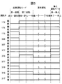
- (A) is an explanatory diagram for explaining the relationship between the turbo generator load, boiler heat generation and steam temperature at each time change when the power plant is started and (b) is when the power plant is stopped. .. It is explanatory drawing for demonstrating the relationship between a turbine generator load, boiler heat output and steam temperature with time change at the time of pumping operation of a power plant.
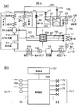
- (A) is a system configuration diagram of the power plant of the first embodiment
- (b) is a configuration diagram of the control device of the first embodiment. It is explanatory drawing for demonstrating the structure of the heat storage apparatus of 1st Embodiment.
- (A) is an explanatory diagram for explaining the open / closed state of the on-off valve of the power plant of the first embodiment, respectively, in the third start operation mode and (b) in the first stop operation mode. .. It is explanatory drawing for demonstrating the open / closed state of the on-off valve of the power plant of 1st Embodiment in the pumping operation mode.
- (A) is an explanatory diagram for explaining the open / closed state of each on-off valve of the heat storage device of the first embodiment, respectively, in the first start-up operation mode (b) in the second start-up operation mode. ..
- (A) is an explanatory diagram for explaining the open / closed state of each on-off valve of the heat storage device of the first embodiment, respectively, in the first stop operation mode and (b) in the pumping operation mode. It is explanatory drawing for demonstrating the open / closed state of each on-off valve of the heat storage apparatus of 1st Embodiment in an emergency operation mode.
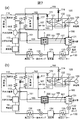
- (A) is a system configuration diagram of the power plant of the second embodiment, and (b) is an explanatory diagram for explaining the configuration of the heat storage device of the second embodiment. It is explanatory drawing for demonstrating the control of the open / closed state of each on-off valve by the control device at the time of starting and stopping of the power plant of 2nd Embodiment.
- (A) and (b) are explanatory views for demonstrating the structure of the heat storage apparatus of the modification of this invention. It is explanatory drawing for demonstrating an example of the relationship between a turbine generator load, a boiler heat output and a steam temperature with time change when a power plant of a modification of this invention is stopped.
- (A) describes the design temperature of each heat exchanger of the boiler of the power plant of the third embodiment
- (b) describes an example of connection at the time of heat recovery from the heat storage device of the third embodiment. It is explanatory drawing for this.
- (A) and (b) are explanatory views for explaining the recovery opportunity of the heat energy stored in the heat storage device of the third embodiment, respectively.
- (A) is an explanatory diagram for explaining a connection example at the time of heat recovery, respectively, of the fourth embodiment and (b) of the modified example. It is explanatory drawing for demonstrating the structural example of the heat storage apparatus of the modification of 4th Embodiment. It is a system block diagram of the power plant of the fifth embodiment. It is explanatory drawing for demonstrating the structural example of the heat storage apparatus of 5th Embodiment. It is explanatory drawing for demonstrating the connection example at the time of heat recovery of 5th Embodiment. It is explanatory drawing for demonstrating the structural example of the heat storage apparatus of the modification of 5th Embodiment. It is explanatory drawing for demonstrating the connection example at the time of heat recovery of the modification of the 5th Embodiment. It is explanatory drawing for demonstrating connection to the heat storage apparatus including the system block diagram of the power generation plant of the modification of 5th Embodiment.
- a power plant includes a boiler that generates steam by heat obtained by burning fuel and a steam turbine that generates power by rotating a turbine using the steam generated by the boiler.
- the surplus heat energy of the embodiment is generated by the difference between the amount of heat generated by the steam generated by the boiler (referred to as boiler output heat or boiler load) and the amount of heat required by the steam turbine (referred to as turbine generator load). To do.
- the entire amount of boiler heat output is not used in the steam turbine after the boiler is ignited and before the boiler starts the once-through operation. This is to warm up the equipment that composes the steam cycle and to stabilize each equipment from the start to the cruise operation. During this time, excess thermal energy is generated.
- the power plant may operate with the turbine generator load smaller than the minimum load of the boiler by a predetermined amount ⁇ .
- Such an operating state occurs, for example, when the system side absorbs fluctuations in the amount of power generation due to natural energy.
- pumped storage operation such an operating state of the power plant is referred to as pumped storage operation.
- surplus thermal energy is generated due to the difference between the boiler heat output and the steam turbine generator load even during this pumping operation.
- excess heat energy that is output from the boiler in the state of steam and is not used in the steam turbine is stored in a heat storage layer according to the steam temperature at the time of generation. Also, when using it, collect it from the optimum temperature range and use it. As a result, excess heat energy is efficiently stored and used.
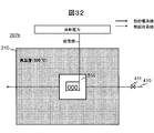
- FIG. 3A is a fluid system diagram of the power plant 100 of the present embodiment.
- the boiler 110 that burns fuel and generates steam (superheated steam) by the heat of the combustion, and the generator 109 by rotating a turbine using the steam generated by the boiler 110.
- the steam turbine 120 that drives and generates power
- the water supply line 130 that returns the exhaust steam from the steam turbine 120 to water and supplies it to the boiler 110, and the thermal energy of the steam that is overheated by the boiler 110, the excess thermal energy is used.
- It includes a heat storage device 200 for storing heat and a control device 150 (see FIG. 3B).
- the boiler 110 includes an economizer (ECO) 111, a fireplace water cooling wall 112, a brackish water separator 113, a superheater 114, and a reheater 115.
- ECO economizer
- the superheater 114 and the reheater 115 are provided in a plurality of stages from the downstream to the upstream.
- the number of superheaters 114 and reheaters 115 may be one.
- the steam turbine 120 includes a high-pressure steam turbine (HPT) 121, a medium-pressure steam turbine (IPT) 122, and a low-pressure steam turbine (LPT) 123, which perform predetermined tasks for rotationally driving the generator 109, respectively.
- HPT high-pressure steam turbine
- IPT medium-pressure steam turbine
- LPT low-pressure steam turbine
- the medium-pressure steam turbine 122 and the low-pressure steam turbine 123 are also collectively referred to as a medium-low pressure steam turbine.
- a condenser 131 On the water supply line 130, a condenser 131, a condenser pump 132, a low-pressure feed water heater (low-pressure heater) 133, a deaerator 134, a water supply pump 135, and a high-pressure feed water heater (high-pressure heater) 136. And are provided.
- the economizer 111 preheats the supplied water by heat exchange with the combustion gas.
- the water preheated by the economizer 111 produces a water-steam two-phase fluid in the furnace water cooling wall 112 by passing through a furnace wall pipe (not shown) formed on the wall.
- the water-steam two-phase fluid generated in the furnace water cooling wall 112 is sent to the brackish water separator 113 and separated into saturated steam and saturated water.
- the saturated steam is guided to the superheater 114, and the saturated water is guided to the condenser 131 through the saturated water pipe 161.
- the saturated steam separated by the steam water separator 113 is superheated by the superheater 114 by heat exchange with the combustion gas, and the generated superheated steam is introduced into the high-pressure steam turbine 121 via the main steam pipe 162.
- the superheater 114 is provided in a plurality of stages. From the front of the superheater 114 in the final stage, some steam is guided to the condenser 131 through the boiler bleeding pipe 165.
- the boiler extraction pipe 165 is provided with a boiler activation extraction air adjustment valve (heater bypass valve; EC) 175.
- the steam that has performed the predetermined work in the high-pressure steam turbine 121 is guided to the reheater 115 via the low-temperature reheat steam pipe 163.
- the reheater 115 reheats the steam that has performed the predetermined work in the high pressure steam turbine 121.
- the steam superheated by the reheater 115 is supplied to the medium-pressure steam turbine 122 and the low-pressure steam turbine 123 via the high-temperature reheat steam pipe 164, where they perform work and drive the generator 109.
- the main steam pipe 162 is provided with a main steam on-off valve 172.
- the high temperature reheat steam pipe 164 is provided with a reheat steam on-off valve 174.
- the steam that has finished its work in the low-pressure steam turbine 123 is introduced into the condenser 131 by the turbine exhaust pipe 166.
- the condensate condensed by the condenser 131 is sent to the deaerator 134 after passing through the low pressure heater 133 by the condensate pump 132 together with the saturated water sent from the brackish water separator 113, and the gas component in the condensate is removed. Will be done.
- the condensate that has passed through the deaerator 134 is further boosted by the water supply pump 135, then fed to the high-pressure heater 136 to be heated, and finally returned to the boiler 110.
- the power plant 100 includes a main steam bypass pipe 167 that branches from the main steam pipe 162 and guides the steam to the condenser 131 by bypassing the high-pressure steam turbine 121.
- the main steam bypass pipe 167 is provided with a main steam bypass on-off valve 177.
- the heat storage device 200 of the present embodiment is arranged on the saturated water pipe 161, the boiler bleeding pipe 165, and the main steam bypass pipe 167.
- the heat storage device 200 stores the thermal energy of steam or saturated water flowing in the saturated water pipe 161 and the boiler extraction pipe 165 and the main steam bypass pipe 167 by heat exchange.
- the steam or saturated water after heat exchange in the heat storage device 200 is introduced into the condenser 131 via the respective pipes.
- temperature sensors 181, 185, and 187 for detecting the temperature of steam passing through the inside of the saturated water pipe 161 and the boiler extraction pipe 165 and the main steam bypass pipe 167 are appropriately provided.
- the control device 150 is instructed from the outside (control table 151 or the like placed in the power plant), or the temperature sensors 181, 185, and the temperature sensors 181 and 185 installed in the power plant 100.
- the opening and closing of each on-off valve in the power plant 100 is controlled according to signals from various sensors including 187.
- the main steam on-off valve 172, the reheated steam on-off valve 174, the boiler start bleed air adjusting valve 175, and the main steam bypass on-off valve 177 of the present embodiment are opened and closed according to the operation mode. The details of the opening / closing timing of each on-off valve will be described later.
- the on-off valve whose opening / closing is controlled by the control device 150 also includes an on-off valve included in the heat storage device 200, which will be described later.
- the control device 150 includes, for example, a CPU, a memory, and a storage device, and the CPU loads a program stored in the storage device in advance into the memory and executes the control to realize the above control.
- Heat storage device 200 of the present embodiment will be described with reference to FIG.
- the steam, water, etc. that return in the power plant 100 will be referred to as a fluid when it is not necessary to distinguish them.
- the heat storage device 200 of the present embodiment stores excess heat energy of the fluid in the power plant 100 according to the instruction from the control device 150.
- the heat storage device 200 of the present embodiment includes a plurality of heat storage layers composed of heat storage materials having temperature characteristics (melting points) in different temperature ranges, a heat exchange unit provided in each heat storage layer, and the heat storage device 200. It regulates the inflow of fluid into each flow path and the flow path that connects and guides the fluid in the pipe to the heat exchange section or bypasses the heat storage device 200 and guides the fluid in the pipe to the water condensing device 131. It is equipped with an on-off valve (valve).
- valve on-off valve
- the path through which the fluid passes is changed according to the temperature of the fluid flowing into the heat storage device 200.
- the route change is realized by a command from the control device 150 to the on-off valve (valve) provided in each flow path described later.
- the heat storage device 200 has a high temperature heat storage layer 210 (hereinafter, also simply referred to as a high temperature layer 210), a medium temperature heat storage layer 220 (medium temperature layer 220), and a low temperature heat storage layer 230 (low temperature) as heat storage layers.
- a high temperature heat storage layer 210 hereinafter, also simply referred to as a high temperature layer 210
- medium temperature heat storage layer 220 medium temperature layer 220
- a low temperature heat storage layer 230 low temperature
- the high temperature layer 210 is a heat storage layer composed of a heat storage material having a temperature characteristic (melting point) in a temperature range (first temperature range) centered on 500 ° C.
- the medium temperature layer 220 is a heat storage layer composed of a heat storage material having a temperature characteristic in a temperature range (second temperature range) centered on 400 ° C.
- the low temperature layer 230 is a heat storage layer composed of a heat storage material having a temperature characteristic in a temperature range (third temperature range) centered on 300 ° C.
- a high temperature heat exchange unit 211 arranged in the high temperature layer 210 and a first medium heat exchange unit arranged in the medium temperature layer 220. It includes an exchange unit 221 and a second medium temperature heat exchange unit 222, and a first low temperature heat exchange unit 231, a second low temperature heat exchange unit 232, and a third low temperature heat exchange unit 233 arranged in the low temperature layer 230.
- Each heat exchange unit (high temperature heat exchange unit 211, first medium temperature heat exchange unit 221, second medium temperature heat exchange unit 222, first low temperature heat exchange unit 231, second low temperature heat exchange unit 232, third The low temperature heat exchange unit 233) exchanges heat with the inflowing fluid.
- a fluid having a temperature equal to or higher than the melting point of the arranged heat storage layer flows in it functions as a heat storage unit that stores heat energy in the heat storage layer.
- the heat energy stored in the heat storage layer is dissipated.
- the heat storage device 200 has a main steam first flow path 371, a main steam bypass flow path 372, a main steam third flow path 373, a boiler exhaust flow path 351 and a boiler exhaust bypass flow as flow paths used during heat storage.
- a path 352, a saturated water flow path 311 and a saturated water bypass flow path 312 are provided.
- the main steam first flow path 371 is connected to the main steam bypass pipe 167.
- the main steam bypass pipe 167 is branched at the branch point 301, and the high temperature heat exchange section 211, the first medium temperature heat exchange section 221 and the first low temperature heat exchange section 231 are connected in this order, and at the confluence point 302. Connect to the main steam bypass pipe 167.
- the main steam first flow path 371 passes the fluid flowing from the main steam bypass pipe 167 into the heat storage device 200 in the order of the high temperature heat exchange unit 211, the first medium heat exchange unit 221 and the first low temperature heat exchange unit 231. And discharge from the heat storage device 200.
- the fluid passing through the main steam first flow path 371 exchanges heat in each heat storage layer and stores heat in each heat storage layer.
- the thermal energy of the fluid is stored in the order of the high temperature layer 210, the medium temperature layer 220, and the low temperature layer 230.
- the fluid discharged from the heat storage device 200 returns to the condenser 131 via the main steam bypass pipe 167.
- the main steam bypass flow path 372 bypasses the heat storage device 200 with the fluid in the main steam bypass pipe 167.
- the fluid bypassing the heat storage device 200 returns to the condenser 131 via the main steam bypass pipe 167.
- the main steam bypass flow path 372 branches at the branch point 301, bypasses the high temperature heat exchange section 211, the first medium temperature heat exchange section 221 and the first low temperature heat exchange section 231, and becomes the main steam bypass pipe 167 at the confluence point 302. Meet.
- the main steam third flow path 373 branches from the main steam bypass flow path 372, bypasses the high temperature heat exchange section 211, and joins the main steam first flow path 371.
- the main steam third flow path 373 allows the fluid flowing into the heat storage device 200 from the main steam bypass pipe 167 to pass through the first medium temperature heat exchange section 221 and the first low temperature heat exchange section 231 in this order, and the heat storage device 200. Discharge from.
- the temperature of the supplied fluid is higher than the melting point of the medium temperature layer 220, the heat energy of the fluid is stored in the order of the medium temperature layer 220 and the low temperature layer 230.
- the fluid discharged from the heat storage device 200 returns to the condenser 131 via the main steam bypass pipe 167.
- the boiler exhaust flow path 351 is connected to the boiler bleeding pipe 165.
- the boiler exhaust flow path 351 branches from the boiler bleeding pipe 165 at a branch point 303, connects the second medium temperature heat exchange section 222 and the second low temperature heat exchange section 232 in this order, and connects to the boiler bleeding pipe 165 at the confluence point 304. To do.
- the boiler exhaust flow path 351 passes the fluid flowing into the heat storage device 200 from the boiler extraction pipe 165 in the order of the second medium temperature heat exchange unit 222 and the second low temperature heat exchange unit 232, and discharges the fluid from the heat storage device 200. ..
- the fluid passing through the boiler exhaust flow path 351 exchanges heat in each heat storage layer and stores heat in each heat storage layer.
- the fluid discharged from the heat storage device 200 returns to the condenser 131 via the boiler extraction pipe 165.
- the boiler exhaust bypass flow path 352 bypasses the heat storage device 200 for the fluid in the boiler extraction pipe 165.
- the fluid bypassing the heat storage device 200 returns to the condenser 131 via the boiler extraction pipe 165.
- the boiler exhaust bypass flow path 352 branches at a branch point 303, bypasses the second medium temperature heat exchange section 222 and the second low temperature heat exchange section 232, and joins the boiler exhaust flow path 351 at the confluence point 304.
- the saturated water flow path 311 is connected to the saturated water pipe 161. It branches from the saturated water pipe 161 at the branch point 305 and is connected to the saturated water pipe 161 at the confluence point 306 via the third low temperature heat exchange unit 233. As a result, the saturated water flow path 311 allows the fluid flowing into the heat storage device 200 from the saturated water pipe 161 to pass through the third low-temperature heat exchange unit 233 and is discharged from the heat storage device 200. The fluid passing through the saturated water flow path 311 exchanges heat in the low temperature layer 230 and stores heat in the low temperature layer 230. The fluid discharged from the heat storage device 200 returns to the condenser 131 via the saturated water pipe 161.
- the saturated water bypass flow path 312 bypasses the heat storage device 200 and returns the fluid in the saturated water pipe 161 to the condenser 131.
- the saturated water bypass flow path 312 branches at the branch point 305, bypasses the third low temperature heat exchange section 233, and joins the saturated water flow path 311 at the confluence point 306.
- the thermal energy of the fluid is stored in the low temperature layer 230.
- each flow path is equipped with an on-off valve (valve).
- the on-off valves the main steam first on-off valve 376, the main steam second on-off valve 377, the main steam third on-off valve 378, the exhaust first on-off valve 356, and the exhaust second on-off valve 357
- a saturated water first on-off valve 316 and a saturated water third on-off valve 317 are provided.
- the main steam first on-off valve 376 is provided downstream of the branch point 301 of the main steam first flow path 371 and controls the inflow of fluid into the high temperature heat exchange unit 211.
- the main steam third on-off valve 378 is provided downstream of the branch point of the main steam third flow path 373 with the main steam bypass flow path 372, and controls the inflow of fluid into the main steam third flow path 373.
- the main steam second on-off valve 377 is provided downstream of the branch point of the main steam bypass flow path 372 with the main steam third flow path 373, and controls the inflow of fluid into the main steam bypass flow path 372.
- the exhaust first on-off valve 356 is provided downstream of the branch point 303 of the boiler exhaust flow path 351 and controls the inflow of fluid into the second medium heat exchange unit 222.
- the second exhaust on-off valve 357 is provided in the boiler exhaust bypass flow path 352 and controls the inflow of fluid into the boiler exhaust bypass flow path 352.
- the saturated water first on-off valve 316 is provided downstream of the branch point 305 of the saturated water flow path 311 and controls the inflow of fluid into the third low temperature heat exchange unit 233.
- the saturated water third on-off valve 317 is provided in the saturated water bypass flow path 312 and controls the inflow of fluid into the saturated water bypass flow path 312.
- Each on-off valve is opened and closed according to a command from the control device 150.
- the control device 150 detects the temperature of the fluid flowing into the heat storage device 200 according to the instruction input via the control console 151, and opens and closes each on-off valve according to the temperature, so that the fluid inflow path To control.
- the opening and closing of the on-off valve is controlled so that the heat is stored in the heat storage layer of the heat storage material which is lower than the temperature and has the closest melting point according to the temperature of the inflowing fluid.
- on-off valve control will be described later.
- the heat storage material used for each heat storage layer for example, a latent heat storage material utilizing the phase transformation latent heat of the substance can be used.
- the temperature characteristic of the heat storage layer is a characteristic determined based on the melting temperature (melting point) of the latent heat storage material.
- an alloy-based material having a heat storage temperature (melting point) exceeding 500 ° C. may be used.
- the structure may include the alloy-based material in ceramics or metal.
- the latent heat storage microcapsules disclosed in International Publication No. 2017/200021 can be used.
- the heat storage material having a structure in which the latent heat storage material is included in each heat storage layer by ceramics or the like, it is possible to obtain a heat storage unit that operates only by inputting and receiving heat using the phase transformation of the latent heat storage material. Since the melting temperature can be controlled by the composition of the latent heat storage material at the time of manufacture, the temperature range of the fluid can be set more finely.
- each heat storage layer As the heat storage material used for each heat storage layer, a material having a melting point in the temperature range is selected according to the temperature range of the heat energy stored in the heat storage device 200. Further, the heat storage capacity of each heat storage layer is determined based on the assumed amount of surplus heat energy. As a result, heat can be efficiently stored without wasting the generated excess heat energy. This also leads to optimization of capital investment.
- the heat storage device 200 includes a first heat recovery tube 410 that passes through the high temperature heat exchange section 211 of the high temperature layer 210, and a first medium temperature exchange section 221 and a second medium heat exchange of the medium temperature layer 220.
- a first heat recovery tube 410 that passes through the high temperature heat exchange section 211 of the high temperature layer 210
- a second heat recovery tube 420 that passes through section 222
- a third heat recovery tube 430 that passes through the first low temperature heat exchange section 231 of the low temperature layer 230, the second low temperature heat exchange section 232, and the third low temperature heat exchange section 233.
- the first heat recovery tube 410 recovers heat only from the high temperature layer 210 by passing the fluid through only the high temperature layer 210 at the time of heat recovery.
- the second heat recovery tube 420 recovers heat only from the middle temperature layer 220 by passing the fluid through only the middle temperature layer 220.
- the third heat recovery tube 430 recovers heat only from the low temperature layer 230 by passing the fluid through only the low temperature layer 230.
- the first heat recovery tube 410, the second heat recovery tube 420, and the third heat recovery tube 430 have a first heat recovery on-off valve 411 and a second heat recovery on-off valve 421 on the inlet side of each heat storage layer, respectively.
- a third heat recovery on-off valve 431 is provided.
- the opening and closing of these heat recovery on-off valves 411, 421 and 431 is controlled by the control device 150.
- the control device 150 controls the opening and closing of these heat recovery on-off valves 411, 421 and 431 so that heat can be recovered from the heat storage layer in the optimum temperature range during heat recovery.
- the control device 150 of the present embodiment stores the surplus heat energy in the steam state generated when the power plant 100 is started, stopped, or during pumping operation, etc., in the heat storage device 200 for each temperature range. Controls the opening and closing of each on-off valve.
- the power generation plant 100 of the present embodiment has a start operation mode which is an operation mode at the time of start, a normal operation mode which is an operation mode at the normal time, a pumping operation mode which is an operation mode at the time of pumping operation, and a stop. It has a stop operation mode, which is an operation mode at the time, and an emergency operation mode, which is an operation mode when a system fails.
- a start operation mode which is an operation mode at the time of start
- a normal operation mode which is an operation mode at the normal time
- a pumping operation mode which is an operation mode at the time of pumping operation
- a stop which is an operation mode at the time
- an emergency operation mode which is an operation mode when a system fails.
- the control device 150 controls the on-off valve so as to store heat in different heat storage layers depending on the temperature of the surplus heat energy.
- start-up operation mode as shown in FIG. 1A, there are events such as ignition of the boiler 110, start of ventilation to the steam turbine 120, incorporation of the generator 109 into the system, and equilibrium, from the boiler 110.
- the temperature of the output steam rises monotonically over time.
- stop operation mode as shown in FIG. 1B, there are events such as equilibrium end and stop, and the temperature of steam output from the boiler 110 decreases monotonically.
- the pumping operation mode as shown in FIG. 2
- the steam temperature output from the boiler 110 is substantially constant.
- the equilibrium refers to a state in which the amount of heat generated by the boiler per unit time and the load on the turbine generator are in equilibrium.
- the end of equilibrium refers to the time when the amount of heat output from the boiler becomes dominant and a difference occurs between the amount of heat output from the boiler and the load on the turbine generator, which have been balanced after receiving the instruction to stop.
- the control device 150 divides the start operation mode and the stop operation mode into a plurality of operation modes according to the steam temperature, and opens / close control different for each operation mode. I do.
- opening / closing control is performed as one operation mode.
- the first start-up operation mode is from the ignition of the boiler 110 to the start of ventilation to the steam turbine 120, and the second is from the start of ventilation to the equilibrium.
- the start operation mode from equilibrium to normal operation, is set as the third start operation mode.
- the stop operation mode as shown in FIG. 1B, the first stop operation mode is set from the end of equilibrium to the stop.
- each operation mode shifts to each operation mode by receiving an instruction from the operator via the control console 151.
- the control device 150 may make a determination based on the temperature detected by the temperature sensors arranged in each pipe. For example, in the start-up operation mode, from the first start-up operation mode to the second start-up operation mode, the temperature detected by the temperature sensor 187 arranged on the main steam bypass pipe 167 or the like is set to a predetermined threshold value (for example, 500 ° C.). ) It may be configured to shift when the above is reached.
- a predetermined threshold value for example, 500 ° C.
- the opening and closing of the on-off valve provided in each pipe of the power plant 100 is controlled according to the operation mode. Further, the opening / closing of the on-off valve provided in each flow path of the heat storage device 200 is controlled according to the temperature of the fluid on the inlet side of each flow path detected by the temperature sensors 181, 185, and 187.
- the open / closed state of each on-off valve for each operation mode is stored in advance in the storage device of the control device 150 as an open / close state table.
- each on-off valve is in the closed state in the initial state unless otherwise specified.
- FIGS. 5 and 6 The time chart of opening and closing of each on-off valve by the control device 150 for each operation mode and event is shown in FIGS. 5 and 6. 7 (a) to 9 are views for explaining the open / closed state of the on-off valve in the power plant 100 for each operation mode.
- the control device 150 issues a close command to the boiler start bleed air adjusting valve 175 as shown in FIGS. 5 and 7 (b), while the main An open command is issued to the steam on-off valve 172 and the reheat steam on-off valve 174.
- the steam generated in the boiler 110 is supplied to the steam turbine 120.
- a part of the surplus steam is guided to the heat storage device 200 via the main steam bypass pipe 167.
- the control device 150 outputs a close command to the main steam bypass on-off valve 177 as shown in FIGS. 5 and 8A, and the state is closed. To do. As a result, the steam generated in the boiler 110 is supplied to the steam turbine 120. After that, when the mode shifts to the normal operation mode, steam and water circulate between the boiler 110, the steam turbine 120, and the water supply line 130, and the generator 109 is driven.
- the control device 150 upon receiving the operation command in the first stop operation mode, the control device 150 outputs an open command to the main steam bypass on-off valve 177 as shown in FIGS. 5 and 8 (b), and the open state is set. To do. As a result, the steam generated by the boiler 110 is supplied to the steam turbine 120 as in the second start operation mode. At this time, a part of the surplus steam is guided to the heat storage device 200 via the main steam bypass pipe 167.
- the control device 150 causes the main steam on-off valve 172 and the reheated steam on-off valve 174 to move as shown in FIGS. 6 and 9. Leave it open.
- an open command is output to the main steam bypass on-off valve 177 to open the valve.
- the boiler start bleeding adjustment valve 175 is closed as it is.
- the steam generated in the boiler 110 is supplied to the steam turbine 120. Further, the surplus steam is guided to the heat storage device 200 via the main steam bypass pipe 167.
- control device 150 controls the opening and closing of each on-off valve according to the temperature of the surplus heat energy generated in each operation mode.
- the opening and closing of each on-off valve is controlled so that the generated excess thermal energy flows into the flow path that first passes through the heat storage unit having the temperature characteristic in the temperature range to which the temperature belongs in the form of a fluid.
- the emergency operation mode is an emergency operation mode such as a system failure.
- the heat recovery on-off valves 411, 421, and 431 are omitted. At the time of heat storage, these heat recovery on-off valves 411, 421 and 431 are basically kept in a closed state.
- the steam temperature is 400 ° C. or higher and less than 500 ° C. Therefore, the control device 150 controls the opening and closing of the on-off valve so that it flows into the flow path that first passes through the heat storage unit having the temperature characteristic in this temperature range.
- the control device 150 opens the main steam third on-off valve 378, the exhaust first on-off valve 356, and the saturated water first on-off valve 316, and other main steam.
- the first on-off valve 376, the main steam second on-off valve 377, the exhaust second on-off valve 357, and the saturated water third on-off valve 317 are closed.
- the fluid below 500 ° C. flowing into the heat storage device 200 is guided to the heat exchange section in the medium temperature layer 220 and the low temperature layer 230.
- the fluid flowing in from the main steam bypass pipe 167 enters the first medium heat exchange section 221 via the main steam bypass flow path 372 and the main steam third flow path 373. After heat exchange in the first medium heat exchange unit 221, the fluid whose temperature has dropped flows into the first low temperature heat exchange unit 231. After heat exchange in the first low temperature heat exchange unit 231, the fluid whose temperature has dropped further is discharged from the heat storage device 200 to the condenser 131 via the main steam bypass pipe 167.
- the fluid flowing from the boiler bleeding pipe 165 into the boiler exhaust flow path 351 enters the second medium heat exchange section 222. After heat exchange in the second medium heat exchange unit 222, the fluid whose temperature has dropped flows into the second low temperature heat exchange unit 232. After heat exchange in the second low temperature heat exchange unit 232, the fluid whose temperature has dropped further is discharged from the heat storage device 200 to the condenser 131 via the boiler extraction pipe 165.
- the steam temperature is 500 ° C. or higher.
- the boiler start bleeding adjustment valve 175 is closed. Therefore, as shown in FIGS. 5 and 10B, the control device 150 opens the main steam first on-off valve 376 and the saturated water first on-off valve 316, and opens the main steam second on-off valve 377 and the main steam first on-off valve.
- the on-off valve 378, the exhaust first on-off valve 356, the exhaust second on-off valve 357, and the saturated water third on-off valve 317 are closed. As a result, as shown by the thick line in this figure, the fluid having a temperature of 500 ° C.
- the heat storage device 200 or higher flowing into the heat storage device 200 is guided to the heat exchange section in the high temperature layer 210, the medium temperature layer 220, and the low temperature layer 230. Further, the water below 100 ° C. flowing from the brackish water separator is guided to the low temperature layer 230 as in the first start operation mode.
- the fluid flowing from the main steam bypass pipe 167 into the main steam first flow path 371 enters the high temperature heat exchange section 211. After heat exchange in the high temperature heat exchange unit 211, the fluid whose temperature has dropped enters the first medium heat exchange unit 221. After heat exchange in the first medium heat exchange unit 221, the fluid whose temperature has dropped flows into the first low temperature heat exchange unit 231. After heat exchange in the first low temperature heat exchange unit 231, the fluid whose temperature has dropped further is discharged from the heat storage device 200 to the condenser 131 via the main steam bypass pipe 167.
- the fluid flowing into the saturated water flow path 311 from the saturated water pipe 161 that guides water from the steam separator 113 to the condenser 131 enters the third low-temperature heat exchange unit 233 and enters the third low-temperature heat exchange unit 233 as in the first start-up operation mode. After heat exchange in the low temperature heat exchange unit 233, the heat is discharged to the condenser 131 via the saturated water pipe 161.
- FIG. 11A shows the state of the on-off valve in the first stop operation mode.
- the steam temperature is 500 ° C. or higher in the first stop operation mode. Therefore, as shown in FIGS. 5 and 11A, the control device 150 controls the opening and closing of each on-off valve as in the second start-up operation mode.
- FIG. 11 (b) The state of the on-off valve in the pumping operation mode is shown in FIG. 11 (b). As shown in FIG. 2, the steam temperature is 500 ° C. or higher in the pumping operation mode. Therefore, as shown in FIGS. 6 and 11B, the control device 150 basically controls the opening and closing of each on-off valve in the same manner as in the second start-up operation mode. However, the saturated water first on-off valve 316 is closed.
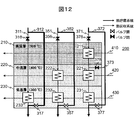
- FIG. 12 shows the state of the on-off valve in the emergency operation mode.
- the control device 150 controls to bypass the heat storage device 200 and guide the fluid to the condenser 131 without guiding the fluid to the heat storage device 200.
- the main steam second on-off valve 377, the exhaust second on-off valve 357, and the saturated water third on-off valve 317 are opened, and the other on-off valves, the main steam first on-off valve 376, and the main The steam third on-off valve 378, the exhaust first on-off valve 356, and the saturated water first on-off valve 316 are closed.
- the fluid does not flow into the heat exchange section in the heat storage device 200, but is discharged to the condenser 131.
- the temperature range of each heat storage layer is determined according to the steam temperature at the time of events such as ignition, ventilation start, merge, equilibrium, equilibrium end, and stop in each operation mode. Further, the heat storage capacity of each heat storage layer is such that the amount of surplus heat energy generated in each heat storage period can be stored.
- the power plant 100 of the present embodiment is provided with a pipe for guiding the fluid having thermal energy to the heat storage device 200 and a pipe for guiding the fluid to the heat storage device 200 only when excess heat energy is generated.
- a control device 150 for controlling an on-off valve is provided.
- the heat storage device 200 includes a plurality of heat storage layers each having temperature characteristics in a plurality of different temperature ranges, a flow path for passing a fluid through each heat storage layer, and an on-off valve provided in the flow path.
- the control device 150 controls to guide the fluid to the heat storage device 200
- the control device 150 controls the heat energy of the fluid flowing into the heat storage device 200 to be stored in the heat storage layer according to the temperature range of the fluid.
- the surplus heat energy generated in the power plant 100 can be stored in a mode in which it can be used efficiently.
- the surplus heat energy generated during the period when the boiler heat output at the start and stop of the power plant 100 exceeds the turbine generator load is appropriate according to the steam temperature and the temperature of the saturated water. Heat can be stored in the heat storage layer in the temperature range.
- the temperature of the surplus steam was low, the total amount of heat was large during the period until the start-up.
- all the surplus steam generated is returned to the condenser 131. Therefore, not only is there a lot of waste, but also a large receiving capacity is required on the condenser 131 side.
- most of the heat of the fluid returned to the condenser 131 is stored in the heat storage device 200, so that the capacity of the condenser 131 can be suppressed. Therefore, the equipment cost can be suppressed.
- each heat storage layer a latent heat storage material that utilizes the phase transformation latent heat of the substance and has a different melting point is used.
- the generated surplus heat energy can be stored in each heat storage layer according to the melting point of the latent heat storage material forming the heat storage layer.
- a latent heat storage material is used, it is possible to realize a heat storage unit capable of high-density heat storage that operates only by input / output of heat.
- a high heat storage temperature can be realized by using an alloy-based material having a high melting point as the latent heat storage material.
- a high-temperature fluid such as main steam can be stored at the same high temperature.
- a flow path is provided so as to flow into the heat storage layer of the heat storage material having a melting point lower than the temperature and having the closest melting point according to the temperature of the fluid flowing into the heat storage device 200. Controls the opening and closing of the on-off valve. Therefore, it is possible to realize heat storage for each of a plurality of temperature ranges with a simple configuration.
- each flow path in the heat storage device 200 is provided so that the fluid that has passed through the heat storage layer also passes through the heat storage layer if there is a heat storage layer composed of the heat storage material having the next highest melting point after the heat storage material. Be done. That is, by arranging the heat storage layers in the order of high temperature, medium temperature, and low temperature in one flow path, the heat of the fluid can be completely recovered. According to the power generation plant 100 having the heat storage device 200 of the present embodiment, the efficient operation of the power generation plant 100 can be realized, including the utilization of the fully recovered thermal energy for startup and the like.
- a heat storage layer having a performance that is not excessive or insufficient with respect to the temperature range of the fluid is arranged for each temperature range of the fluid.
- the temperature range of each heat storage layer is determined according to the steam temperature after a predetermined time has elapsed after ignition of the boiler 110. Further, the heat storage capacity of each heat storage layer is determined according to the amount of surplus heat energy after the lapse of each time.
- the fluid discharged from the heat storage device 200 to the condenser 131 The temperature goes down. Therefore, the amount of heat returned to the condenser 131 can be suppressed.
- the present embodiment further includes a reheat steam bypass pipe branching from the high temperature reheat steam pipe 164. Then, the heat storage device 200 also stores heat of the fluid passing through the reheat steam bypass pipe.
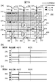
- FIG. 13A is a fluid system diagram of the power plant 101 of the present embodiment.
- the power generation plant 101 of the present embodiment has the configuration of the power generation plant 100 of the first embodiment, and further branches from the reheat steam bypass pipe 168 branching from the high temperature reheat steam pipe 164 and the main steam pipe 162, and high-pressure steam.
- a high-pressure steam turbine bypass pipe 169 that bypasses the turbine 121 and connects to the low-temperature reheat steam pipe 163 is provided. That is, in the present embodiment, the main steam pipe 162 and the low temperature reheat steam pipe 163 are connected to each other via the high pressure steam turbine bypass pipe 169.
- the reheat steam bypass pipe 168 is provided with a reheat steam bypass on-off valve 178.
- the high-pressure steam turbine bypass pipe 169 is provided with a high-pressure steam turbine bypass on-off valve 179.
- the reheated steam bypass pipe 168 is provided with a temperature sensor 188 that detects the temperature of steam passing through the inside.
- the heat storage device 201 of the present embodiment is arranged on the saturated water pipe 161, the boiler bleeding pipe 165, the main steam bypass pipe 167, and the reheat steam bypass pipe 168.
- the steam after heat exchange in the heat storage device 201 is introduced into the condenser 131.
- control device 150 is instructed from the outside (control table 151 or the like placed in the power plant) or is installed in the power generation plant 101 at the above temperature. It controls the opening and closing of each on-off valve according to signals from various sensors including sensors 181, 185, 187, and 188.
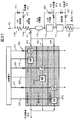
- Heat storage device Next, the heat storage device 201 of this embodiment will be described with reference to FIG. 13 (b).
- the heat storage device 201 of the present embodiment is also provided with a plurality of heat storage layers composed of heat storage materials having temperature characteristics (melting points) in different temperature ranges, and in each heat storage layer.
- valve on-off valve
- the path through which the fluid passes is changed by opening and closing the on-off valve according to the command from the control device 150 according to the temperature of the fluid flowing into the heat storage device 201. And store heat in an appropriate temperature range.
- the high temperature layer 210, the medium temperature layer 220, and the low temperature layer 230 are provided as the heat storage layer will be described as an example.
- the heat exchange unit as in the first embodiment, the high temperature heat exchange unit 211 arranged in the high temperature layer 210, the first medium heat exchange unit 221 arranged in the medium temperature layer 220, and the second medium heat exchange unit
- the exchange unit 222 includes a first low-temperature heat exchange unit 231, a second low-temperature heat exchange unit 232, and a third low-temperature heat exchange unit 233 arranged in the low-temperature layer 230.
- the high temperature layer 210 is provided with the reheat high temperature heat exchange unit 214
- the medium temperature layer 220 is provided with the reheat medium heat exchange unit 224
- the low temperature layer 230 is provided with the reheat low temperature heat exchange unit 234.
- the heat storage device 201 of the present embodiment further includes a reheated steam first flow path 381, a reheated steam bypass flow path 382, and a reheated steam third flow path 383.
- the reheated steam first flow path 381 is connected to the reheated steam bypass pipe 168.
- the reheat steam bypass pipe 168 is branched at the branch point 307, and the reheat high temperature heat exchange unit 214, the reheat medium heat exchange unit 224, and the reheat low temperature heat exchange unit 234 are connected in this order, and the confluence point is reached.
- the reheated steam first flow path 381 allows the fluid flowing into the heat storage device 201 from the reheated steam bypass pipe 168 to be reheated to the high temperature heat exchange unit 214, the reheated medium heat exchange unit 224, and the reheated low temperature heat exchange unit 234.
- the fluid passing through the reheated steam first flow path 381 exchanges heat in each heat storage layer and stores heat in each heat storage layer.
- the thermal energy of the fluid is stored in the order of the high temperature layer 210, the medium temperature layer 220, and the low temperature layer 230.
- the reheat steam bypass flow path 382 bypasses the heat storage device 201 and returns the fluid flowing through the reheat steam bypass pipe 168 to the condenser 131.
- the reheat steam bypass flow path 382 branches at the branch point 307, bypasses the reheat high temperature heat exchange unit 214, the reheat medium heat exchange unit 224, and the reheat low temperature heat exchange unit 234, and reheat steam bypass at the confluence point 308. It joins tube 168.
- the reheated steam third flow path 383 branches from the reheated steam bypass flow path 382, bypasses the reheated high temperature heat exchange section 214, and joins the reheated steam first flow path 381.
- the reheated steam third flow path 383 allows the fluid flowing into the heat storage device 201 from the reheated steam bypass pipe 168 to pass through the reheated medium-temperature heat exchange section 224 and the reheated low-temperature heat exchange section 234 in this order, and the reheated steam storage device It is discharged from 201 and returned to the condenser 131 via the reheat steam bypass pipe 168.
- the temperature of the supplied fluid is higher than the melting point of the medium temperature layer 220, the heat energy of the fluid is stored in the order of the medium temperature layer 220 and the low temperature layer 230.
- the heat storage device 201 includes a main steam first on-off valve 376, a main steam second on-off valve 377, a main steam third on-off valve 378, and an exhaust first on-off valve 356, as in the first embodiment.
- the exhaust second on-off valve 357, the saturated water first on-off valve 316, and the saturated water third on-off valve 317 are provided.
- a third heat recovery on-off valve 431 is provided.
- the reheat steam first on-off valve 386 is provided downstream of the branch point 307 of the reheat steam first flow path 381, and controls the inflow of fluid into the reheat high temperature heat exchange unit 214.
- the reheated steam third on-off valve 388 is provided downstream of the branch point of the reheated steam third flow path 383 with the reheated steam bypass flow path 382, and the fluid flows into the reheated steam third flow path 383. To control.
- the reheat steam second on-off valve 387 is provided downstream of the branch point of the reheat steam bypass flow path 382 with the reheat steam third flow path 383, and allows fluid to flow into the reheat steam bypass flow path 382. Control.
- each on-off valve is opened and closed in response to a command from the control device 150 issued according to the temperature of the fluid flowing through the installed flow path. Since the heat storage material and the like used for each heat storage layer are the same as those in the first embodiment, the description thereof will be omitted here.
- each flow path used at the time of heat recovery, the first heat recovery tube 410, the second heat recovery tube 420 and the third heat recovery tube 430 are further described as a reheat high temperature heat exchange unit 214 and a reheat medium heat exchange unit, respectively.
- 224 and the reheat low temperature heat exchange unit 234 also pass through.
- the opening and closing of the on-off valve provided in each pipe of the power plant 101 is controlled according to the operation mode. Further, the opening and closing of the on-off valve provided in each flow path of the heat storage device 201 is controlled according to the temperature of the fluid on the inlet side of each flow path. Further, the open / closed state of each on-off valve for each operation mode is stored in advance in the storage device of the control device 150 as an open / close state table. In the initial state, each on-off valve is in a closed state unless otherwise specified.
- the opening / closing timing of the on-off valve included in the power plant 100 of the first embodiment is the same as that of the first embodiment.
- the reheated steam bypass on-off valve 178, the reheated steam first on-off valve 386, the reheated steam second on-off valve 387, and the reheated steam third on-off valve 388 of the present embodiment are of the first embodiment. It is the same as 177, 376, 377, 378.
- the high-pressure steam turbine bypass on-off valve 179 is opened when heat is stored in the heat storage device 201. That is, it is opened and closed at the same timing as the reheat steam bypass on-off valve 178.
- control device 150 controls the opening and closing of each on-off valve according to the instruction from the control table 151 and the like.
- the control device 150 may control the opening and closing according to the detection result of each temperature sensor.
- the open / closed state of each on-off valve for each operation mode is stored in advance in the storage device of the control device 150 as an open / close state table.
- the heat recovery on-off valves 411, 421 and 431 are omitted. At the time of heat storage, these heat recovery on-off valves 411, 421 and 431 are basically kept in a closed state.
- the control device 150 includes a main steam third on-off valve 378, a reheated steam third on-off valve 388, an exhaust first on-off valve 356 and saturation, as shown in FIGS. 14 and 16 (a).
- the water first on-off valve 316 is opened, and the other main steam first on-off valve 376, main steam second on-off valve 377, reheated steam first on-off valve 386, reheated steam second on-off valve 387, exhaust second on-off valve 387.
- the valve 357 and the saturated water third on-off valve 317 are closed.
- the fluid below 500 ° C. flowing into the heat storage device 200 is guided to the heat exchange section in the medium temperature layer 220 and the low temperature layer 230.
- the fluid flowing in from the reheated steam bypass pipe 168 enters the reheated medium heat exchange section 224 via the reheated steam bypass flow path 382 and the reheated steam third flow path 383.
- the fluid whose temperature has dropped flows into the reheat low temperature heat exchange unit 234.
- the fluid whose temperature has dropped further is discharged from the heat storage device 201 to the condenser 131 via the reheat steam bypass pipe 168.
- the control device 150 sets the main steam first on-off valve 376, the reheated steam first on-off valve 386, and the saturated water first on-off valve 316, as shown in FIGS. 14 and 16 (b). Opened, main steam second on-off valve 377, main steam third on-off valve 378, reheated steam second on-off valve 387, reheated steam third on-off valve 388, exhaust first on-off valve 356, exhaust second on-off valve 357. , And the saturated water third on-off valve 317 is closed. As a result, as shown by the thick line in this figure, the fluid having a temperature of 500 ° C.
- the heat storage device 201 or higher flowing into the heat storage device 201 is guided to the heat exchange portions in the high temperature layer 210, the medium temperature layer 220, and the low temperature layer 230. Further, the water below 100 ° C. flowing from the brackish water separator is guided to the low temperature layer 230 as in the first start operation mode.
- the fluid whose temperature has dropped enters the reheat medium heat exchange unit 224.
- the fluid whose temperature has dropped flows into the reheat low temperature heat exchange unit 234.
- the fluid whose temperature has dropped further is discharged from the heat storage device 201 to the condenser 131 via the reheat steam bypass pipe 168.
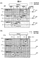
- FIG. 17 (a) shows the state of the on-off valve in the first stop operation mode.
- the control device 150 controls the opening and closing of each on-off valve as in the second start-up operation mode.
- FIG. 17 (b) The state of the on-off valve in the pumping operation mode is shown in FIG. 17 (b).
- the control device 150 basically controls the opening and closing of each on-off valve in the same manner as in the second start-up operation mode. However, the saturated water first on-off valve 316 is closed.
- FIG. 18 shows the state of the on-off valve in the emergency operation mode.
- the control device 150 controls to bypass the heat storage device 201 and guide the fluid to the condenser 131 without guiding the fluid to the heat storage device 201 regardless of the steam temperature.
- the main steam second on-off valve 377, the reheated steam second on-off valve 387, the exhaust second on-off valve 357, and the saturated water third on-off valve 317 are opened, and other on-off valves. Close the main steam first on-off valve 376, main steam third on-off valve 378, reheated steam first on-off valve 386, reheated steam third on-off valve 388, exhaust first on-off valve 356 and saturated water first on-off valve 316. And. As a result, as shown by the thick line in this figure, the fluid does not flow into the heat exchange section in the heat storage device 201, but is discharged to the condenser 131.
- the flow of the fluid flowing into the heat storage device 201 from the main steam bypass pipe 167, the boiler extraction pipe 165, and the saturated water pipe 161 is the same as in the first embodiment.
- the power plant 101 of the present embodiment acquires surplus heat energy from the high temperature reheat steam pipe 164 in addition to the power plant 100 of the first embodiment, and stores the heat in the heat storage device 201.
- excess steam can be efficiently stored even during FCB (Fast Cut Back) operation.
- the heat storage devices 200 and 201 control the opening and closing of the on-off valve according to a predetermined event.
- a temperature threshold value may be set according to the temperature range of the heat storage layer, and the control device 150 may control the opening and closing of the on-off valve according to the temperature threshold value.
- the heat storage device 202 of this modification has the configuration of the heat storage device 200 of the first embodiment, and further includes a main steam fourth flow path 374 and a main steam fourth on-off valve 379.
- the boiler exhaust fourth flow path 354 and the exhaust fourth on-off valve 359 are provided.
- the heat recovery on-off valves 411, 421, and 431 are omitted.
- the main steam fourth flow path 374 branches from the main steam bypass flow path 372, bypasses the high temperature heat exchange section 211 and the first medium temperature heat exchange section 221 and joins the main steam first flow path 371.
- the main steam fourth flow path 374 allows the fluid flowing from the main steam bypass pipe 167 into the heat storage device 202 to pass through the first low temperature heat exchange unit 231 and is discharged from the heat storage device 202, and the main steam bypass pipe 167. After that, it is returned to the condenser 131.
- the main steam fourth on-off valve 379 is provided downstream of the branch point of the main steam fourth flow path 374 with the main steam bypass flow path 372, and controls the inflow of fluid into the main steam fourth flow path 374.
- the fourth boiler exhaust flow path 354 branches from the boiler exhaust bypass flow path 352, bypasses the second medium heat exchange section 222, and joins the boiler exhaust flow path 351.
- the fourth flow path 354 for exhausting the boiler allows the fluid flowing from the boiler extraction pipe 165 into the heat storage device 202 to pass through the second low temperature heat exchange unit 232 and is discharged from the heat storage device 202, and passes through the boiler extraction pipe 165. , Return to the condenser 131.
- the exhaust fourth on-off valve 359 is provided downstream of the branch point of the boiler exhaust fourth flow path 354 with the boiler exhaust bypass flow path 352, and controls the inflow of fluid into the boiler exhaust fourth flow path 354.
- the control device 150 controls the opening and closing of each on-off valve according to the detection results of the temperature sensor 187 provided in the main steam bypass pipe 167 and the temperature sensor 185 provided in the boiler extraction pipe 165.
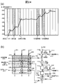
- the timing of opening / closing control when the steam temperature increases monotonically is shown in FIGS. 19 (b) and 19 (c). Since the explanation is for heat storage, the main steam second on-off valve 377 and the exhaust second on-off valve 357 are omitted in these figures.
- the main steam fourth on-off valve 379 is opened in each flow path connected to the main steam bypass pipe 167.
- the other on-off valves, the main steam first on-off valve 376, the main steam second on-off valve 377, and the main steam third on-off valve 378 are closed.
- the fluid is guided to the first low temperature heat exchange unit 231 and heat exchanges in the first low temperature heat exchange unit 231 to bypass the main steam from the main steam first flow path 371. It is discharged to the condenser 131 via the pipe 167.
- the main steam third on-off valve 378 is opened in each flow path connected to the main steam bypass pipe 167, and other on-off valves are used.
- the main steam first on-off valve 376, the main steam second on-off valve 377, and the main steam fourth on-off valve 379 are closed.
- the steam temperature is 400 ° C. or higher and lower than 500 ° C.
- the fluid is guided to the first medium heat exchange unit 221 and the fluid whose temperature has dropped after heat exchange at the first medium heat exchange unit 221 is released. It flows into the first low temperature heat exchange unit 231. After heat exchange in the first low temperature heat exchange unit 231, the fluid whose temperature has dropped further is discharged from the heat storage device 200 to the condenser 131 via the main steam bypass pipe 167.
- the main steam first on-off valve 376 is opened in each flow path connected to the main steam bypass pipe 167, and the other on-off valve, the main steam second, is opened.
- the on-off valve 377, the main steam third on-off valve 378, and the main steam fourth on-off valve 379 are closed.
- the fluid whose temperature has dropped flows into the first low temperature heat exchange unit 231.
- the fluid whose temperature has dropped further is discharged from the heat storage device 200 to the condenser 131 via the main steam bypass pipe 167.
- the exhaust fourth on-off valve 359 is opened in each flow path connected to the boiler bleeding pipe 165.
- the other on-off valves, the first exhaust on-off valve 356 and the second exhaust on-off valve 357, are closed.
- the steam temperature is less than 400 ° C.
- the fluid is guided to the second low temperature heat exchange unit 232, heat exchange is performed by the second low temperature heat exchange unit 232, and the boiler exhaust pipe 165 from the boiler exhaust flow path 351. Is discharged to the condenser 131.
- the exhaust first on-off valve 356 is opened in each flow path connected to the boiler extraction pipe 165, and the other on-off valve, the exhaust first on-off valve, is opened. (Ii) The on-off valve 357 and the exhaust fourth on-off valve 359 are closed.
- the steam temperature is 400 ° C or higher and lower than 500 ° C
- the fluid is guided to the second medium heat exchange unit 222, and after heat exchange at the second medium heat exchange unit 222, the fluid whose temperature has dropped is released. It flows into the second low temperature heat exchange unit 232. After heat exchange in the second low temperature heat exchange unit 232, the fluid whose temperature has dropped further is discharged from the heat storage device 200 to the condenser 131 via the boiler extraction pipe 165.
- the initial steam temperature output from the boiler 110 drops significantly from 500 ° C.
- the heat storage device 202 of the present modification can efficiently store heat in the heat storage layer in the optimum temperature range even in such a case.
- each on-off valve is controlled according to the detection result of the temperature sensor 188 installed in the reheat steam bypass pipe 168, and the fluid is first guided to the heat exchange part of the heat storage layer in the temperature zone corresponding to the detection result. ..
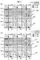
- each heat exchange portion in each heat storage layer may be provided with a flow path so as to be connected in series and in parallel.
- each bypass flow path of the main steam bypass flow path 372, the boiler exhaust bypass flow path 352, and the saturated water bypass flow path 312 is omitted.
- the main steam third flow path 373 allows the fluid flowing into the heat storage device 203 to pass through the first parallel medium heat exchange section 221b and the first parallel low temperature heat exchange section 231b in this order, and is transmitted from the heat storage device 203. Discharge.
- main steam fourth flow path 374 allows the fluid flowing into the heat storage device 203 to pass through the second parallel low temperature heat exchange unit 231c and is discharged from the heat storage device 203.
- the boiler exhaust third flow path 353 allows the fluid flowing into the heat storage device 203 to pass through the third parallel low temperature heat exchange unit 232b and is discharged from the heat storage device 203.
- the opening / closing control of each on-off valve according to the detected values of the temperature sensors 187 and 185 by the control device 150 is the same as that of the first modification.
- each heat exchange portion in each heat storage layer may be provided with a flow path so as to be connected in parallel.
- each bypass flow path of the main steam bypass flow path 372, the boiler exhaust bypass flow path 352, and the saturated water bypass flow path 312 is omitted.
- the main steam third flow path 373 allows the fluid flowing into the heat storage device 204 to pass through the first parallel medium heat exchange unit 221b and is discharged from the heat storage device 203.
- main steam fourth flow path 374 allows the fluid flowing into the heat storage device 203 to pass through the second parallel low temperature heat exchange unit 231c and is discharged from the heat storage device 203.
- the boiler exhaust third flow path 353 allows the fluid flowing into the heat storage device 203 to pass through the third parallel low temperature heat exchange unit 232b and is discharged from the heat storage device 203.
- the opening / closing control of each on-off valve according to the detected values of the temperature sensors 187 and 185 by the control device 150 is the same as that of the first modification.
- one heat exchange unit of the heat storage device 205 may be provided in each heat storage layer for each inflow path.
- An example of the heat storage device 205 in this case is shown in FIG. 22 (a).
- one heat exchange unit is provided in each heat storage layer for each of the main steam bypass pipe 167, the boiler extraction pipe 165, and the saturated water pipe 161 and are connected in series and in parallel.
- the opening / closing control of each on-off valve according to the detected values of the temperature sensors 187 and 185 by the control device 150 is the same as that of the first modification.
- one heat exchange unit of the heat storage device 205 may be provided in each heat storage layer.
- the opening / closing control of each on-off valve according to the detected values of the temperature sensors 187 and 185 in this case is the same as that of the first modification.
- the fluid discharged from the heat storage device 205 is returned to the condenser 131 via any of the main steam bypass pipe 167, the boiler bleeding pipe 165, and the saturated water pipe 161 regardless of the inflow path. ..
- the heat storage device 200 includes three heat storage layers of a high temperature heat storage layer 210, a medium temperature heat storage layer 220, and a low temperature heat storage layer 230 will be described as an example.
- the number of heat storage layers is not limited to this. As long as there are two or more layers, the number does not matter. Further, with respect to each flow path, it is not always necessary to provide a heat exchange unit (heat storage unit) in each heat storage layer.
- the heat storage device 200 has a two-layer structure of a high temperature layer 210 and a medium temperature layer 220
- the heat exchange unit provided in the high temperature layer 210 is the first heat storage unit
- the heat exchange unit provided in the medium temperature layer 220 is.
- the heat exchange unit provided in the medium temperature layer 220 is.
- the heat exchange unit provided in the medium temperature layer 220 is.
- the heat exchange unit provided in the low temperature layer 230 corresponds to the third heat storage unit.
- the heat storage device 200 has a two-layer structure consisting of a medium temperature layer 220 and a low temperature layer 230
- the heat exchange unit provided in the medium temperature layer 220 is the first heat storage unit
- the heat exchange unit provided in the low temperature layer 230 is the first.
- the reduction rate of the generator load of the steam turbine 120 may be increased to be higher than the output reduction of the boiler 110.
- the equilibrium state ends before the boiler 110 reaches the minimum load. Then, the surplus heat energy generated after the end of this equilibrium may be stored.
- the reduction rate of the generator load of the steam turbine 120 can be controlled independently of the output reduction rate of the boiler 110. That is, the reduction rate of the generator load can be increased as compared with the case where the generator load of the steam turbine 120 is reduced in accordance with the decrease in the output of the boiler 110. Therefore, the period until the power plant 100 is stopped can be shortened, and the power plant 100 can be operated efficiently.
- the surplus heat energy generated after the end of equilibrium can be stored in the heat storage device of any of the above-described embodiments and modifications in a manner that can be efficiently used.
- This embodiment is an embodiment of recovering heat energy from a heat storage device having a plurality of heat storage layers in different temperature ranges.
- the heat storage device any of the above-described embodiments and modifications (hereinafter, represented by the heat storage device 200) can be used.
- the heat storage device used is not limited to this.
- the present embodiment will be described by taking the case of using the heat storage device 200 as an example.
- the heat storage device 200 stores heat energy in a plurality of temperature ranges. Therefore, even when the heat is recovered from the heat storage device 200, it can be recovered for each temperature range and can be provided to the user.
- the heat energy recovered from each heat storage layer is supplied to each heat exchanger (boiler heat exchange unit) in the boiler 110 and the high-pressure heater 136 in the front stage of the boiler 110 according to the design temperature. An example is shown.
- FIG. 24 (a) An example of the design temperature of each heat exchanger of the boiler 110 is shown in FIG. 24 (a).
- the boiler 110 includes a primary superheater 114a and a secondary superheater 114b.
- the design temperature on the outlet side of each of the high pressure heater 136 and the economizer 111 is 290 ° C. and 340 ° C.
- the design temperatures of the inlet side and the outlet side of the primary superheater 114a are 430 ° C. and 470 ° C., respectively.
- a part of the fluid supplied to the high-pressure heater 136 is heated by passing through the low-temperature layer 230 and supplied to the outlet side of the high-pressure heater 136 or the outlet side of the economizer 111. Further, a part of the fluid supplied to the economizer 111 is heated by passing through the medium temperature layer 220, and is supplied to the outlet side of the economizer 111 or the outlet side of the furnace water cooling wall 112. Further, a part of the fluid supplied to the primary superheater 114a is heated by passing through the high temperature layer 210, and is supplied to the outlet side of the primary superheater 114a or the outlet side of the secondary superheater 114b.
- the inlet side of the third heat recovery pipe 430 that recovers heat energy from the low temperature layer 230 of the heat storage device 200 is connected to the pipe on the inlet side of the high pressure heater 136.
- the outlet side of the third heat recovery pipe 430 is branched into two, and is connected to the pipe on the outlet side of the high-pressure heater 136 and the outlet side of the economizer 111, respectively.
- the third heat recovery pipe 430 after branching is provided with heat recovery on-off valves 433 and 434, respectively. After recovering heat from the low temperature layer 230, these heat recovery on-off valves 433 and 434 are controlled to open and close by the control device 150 according to the operating state (fluid temperature and the like).
- the third heat recovery pipe 430 is provided with a temperature sensor that detects the temperature of the fluid on the outlet side thereof.
- the control device 150 obtains the fluid temperature after heat recovery from the low temperature layer 230 based on the detected value of the temperature sensor. Then, the opening and closing is controlled so as to return to the boiler heat exchange section having a design temperature higher than the obtained fluid temperature.
- the inlet side of the second heat recovery pipe 420 that recovers heat energy from the medium temperature layer 220 of the heat storage device 200 is connected to the pipe on the inlet side of the economizer 111. Further, the outlet side of the second heat recovery pipe 420 is branched into two, and is connected to the outlet side pipe of the economizer 111 and the outlet side pipe of the furnace water cooling wall 112, respectively.
- the second heat recovery pipe 420 after branching is provided with heat recovery on-off valves 423 and 424, respectively. After recovering heat from the medium temperature layer 220, these heat recovery on-off valves 423 and 424 are controlled to open and close by the control device 150 according to the operating state (fluid temperature and the like).
- the second heat recovery pipe 420 is provided with a temperature sensor that detects the temperature of the fluid on the outlet side thereof.
- the control device 150 obtains the fluid temperature after heat recovery from the medium temperature layer 220 based on the detected value of the temperature sensor. Then, the obtained control device 150 controls opening and closing so as to return to the boiler heat exchange unit having a design temperature higher than the fluid temperature.
- the inlet side of the first heat recovery pipe 410 that recovers heat energy from the high temperature layer 210 of the heat storage device 200 is connected to the pipe on the inlet side of the primary superheater 114a.
- the outlet side of the first heat recovery pipe 410 is branched into two and is connected to the outlet side pipe of the primary superheater 114a and the outlet side pipe of the secondary superheater 114b, respectively.
- the first heat recovery pipe 410 after branching is provided with heat recovery on-off valves 413 and 414, respectively. After recovering heat from the high temperature layer 210, these heat recovery on-off valves 413 and 414 are controlled to open and close by the control device 150 according to the operating state (fluid temperature and the like).
- the first heat recovery pipe 410 is provided with a temperature sensor that detects the temperature of the fluid on the outlet side thereof.
- the control device 150 obtains the fluid temperature after heat recovery from the high temperature layer 210 based on the detected value of the temperature sensor. Then, the obtained control device 150 controls opening and closing so as to return to the boiler heat exchange unit having a design temperature higher than the fluid temperature.
- the fluid passing through the third heat recovery tube 430 passes through the first low temperature heat exchange section 231 and the second low temperature heat exchange section 232 and the third low temperature heat exchange section 233 of the low temperature layer 230, and heat is generated in these heat exchange sections. To collect. As a result, a fluid having a temperature in the temperature range of the low temperature layer 230 is generated. Further, the fluid passing through the second heat recovery pipe 420 passes through the first medium heat exchange section 221 and the second medium heat exchange section 222 of the medium temperature layer 220, and recovers heat in these heat exchange sections. As a result, a fluid having a temperature in the temperature range of the medium temperature layer 220 is generated. The fluid passing through the first heat recovery pipe 410 passes through the high temperature heat exchange unit 211 to recover heat. As a result, a fluid having a temperature in the temperature range of the high temperature layer 210 is generated.
- the control device 150 controls the first heat recovery on-off valve 411, the second heat recovery on-off valve 421, and the third heat recovery on-off valve 431 in an open state.
- the power plants 100 and 101 include temperature sensors that detect the temperature of each heat storage layer.
- the control device 150 monitors the temperature of each heat storage layer detected by these temperature sensors, and determines that the heat recovery is completed when the temperature becomes lower than the predetermined set temperature of each heat storage layer. Then, when it is determined that the heat recovery is completed, the control device 150 controls to close these heat recovery on-off valves 411, 421, and 431, respectively.
- the control device 150 opens the main steam on-off valve 172 and the reheat steam on-off valve 174 in the power plant 100 of the first embodiment. Further, the boiler start air extraction adjustment valve 175 and the main steam bypass on-off valve 177 are closed. Further, in the power plant 101 of the second embodiment, the reheat steam bypass on-off valve 178 and the high-pressure steam turbine bypass on-off valve 179 are further closed.
- the heat storage device 200 of the present embodiment it is possible to independently and independently recover a plurality of heat energies having different temperatures according to the melting point in each heat storage layer at the time of heat recovery. Then, the recovered thermal energy of different temperatures can be provided to the usage destination according to the required temperature. That is, according to the heat storage device 200 of the present embodiment, it is possible to realize proper use of heat according to the application.
- the surplus heat energy is independently stored in the heat storage device 200 for each temperature zone. Therefore, when the heat is recovered from the heat storage device 200, the surplus heat energy can be efficiently used by recovering the heat from the heat storage layer in which the heat energy corresponding to the temperature required by the boiler heat exchange unit to be used is stored.
- the power generation plant 100 may be operated while recovering the surplus heat energy stored in the heat storage device 200 not only at the time of startup but also during normal operation, for example.
- the load on the boiler 110 is reduced while keeping the output of the steam turbine 120 constant (suppression of boiler heat generation). Further, as shown in the figure, the load of the steam turbine 120 is increased while keeping the load of the boiler 110 constant (steam turbine drive promotion).
- the reduction rate of the generator load of the steam turbine 120 is set to be equal to or higher than the output reduction rate of the boiler 110, and occurs during that period.
- the surplus heat energy to be generated is stored in the heat storage device 200.
- the surplus heat energy from the boiler 110 is stored in the heat storage device 200. Then, at startup, these excess heat energies stored in the heat storage device 200 may be recovered. As a result, the startup efficiency is increased.
- the heat storage device 200 of the present embodiment for starting and stopping a steam power plant in DSS (Daily Start & Stop), it is possible to shorten the start and stop time. Further, by using the heat storage device 200 of the present embodiment, the fluctuation of the electric power supply amount derived from the regenerated energy can be leveled in total even when the steam power generation plant and the regenerated energy power generation plant are used in combination. As a result, the number of occurrences of a state in which the overall power supply exceeds the system requirement is reduced.
- the heat storage energy stored in the heat storage device 200 can be utilized not only at the time of normal startup but also at the time of system return after FCB or at the time of rapid load increase of the power plant 100. As a result, the system return time and the load increase time can be shortened.
- the rapid load increase is, for example, a case where a load change that is faster than that at the start / load change / stop during normal operation is required.
- a load increase higher than that of normal startup such as when returning after the system becomes unstable.
- the rate of increase is 5% / min or more
- the rate of increase is 10 to 20% / min or more.
- each heat recovery pipe (first heat recovery pipe 410, second heat recovery pipe 420, and third heat recovery pipe 430) is not limited to the above-mentioned pipes depending on the temperature range of each heat storage layer.
- a heat recovery pipe passing through a heat storage layer in a temperature range higher than and closest to the inlet side temperature of the boiler heat exchange section branches from the inlet side pipe and exits.
- the heat recovery pipe that has passed through the heat storage layer in the temperature range lower than and closest to the side temperature may be connected to the outlet side pipe.
- the boiler 110 has a first boiler heat exchange unit that generates a fluid having a temperature in the first temperature range by heat exchange, and a second temperature range that is lower than the first temperature range by heat exchange.
- a second boiler heat exchange section (or a high-pressure heater 136 of the water supply line 130) for generating fluid, and a first heat storage section (high temperature layer) in which the heat storage device 200 stores heat energy in the first temperature range.
- the second heat recovery tube 420 is provided with a second boiler.
- the first boiler heat exchange section or the first boiler heat exchange section or higher in the boiler 110 Lead to the boiler heat exchange section with the design temperature.
- the first heat recovery tube 410 is a boiler having a design temperature higher than that of the boiler heat exchange section (for example, the first boiler heat exchange section or the first boiler heat exchange section) into which the fluid guided by the second heat recovery tube 420 flows. A part of the fluid generated in the heat exchange section) is guided to the first heat storage section, and after the heat energy is recovered in the first heat storage section, it is guided to the outlet side of the boiler heat exchange section.
- the heat recovery method from the heat storage device 200 is not limited to this.
- the fluid may be passed through each layer in order from the low temperature layer 230, the entire heat energy stored in the heat storage device 200 may be recovered, and then returned to the system of the power plant 100.
- the return destination of the fluid after the thermal energy is recovered is, for example, the main steam pipe 162. Further, the fluid to the heat storage device 200 is supplied from, for example, the water supply line 130. In this case, for example, a fourth heat recovery pipe 440 that connects the water supply line 130 and the main steam pipe 162 is provided, and the heat storage device 200 is arranged on the fourth heat recovery pipe 440.
- the water charged into the heat storage device 200 is heated in the order of the low temperature layer 230, the medium temperature layer 220, and the high temperature layer 210.
- high-temperature, high-pressure steam is generated only in the heat storage device 200, and it can be directly input to the high-pressure steam turbine 121.
- the return destination of the fluid after the heat energy is recovered by the heat storage device 200 may be the low temperature reheat steam pipe 163 during high load operation.
- renewable energy such as wind power or solar power
- regenerative energy power generations depend on natural phenomena such as the weather, and the amount of power generation fluctuates rapidly.
- fluctuations in the amount of power generation due to regenerative energy power generation are absorbed by adjusting the power generation amount of the thermal power generation plant in order to maintain the stability of the power system. Therefore, when the amount of power supplied by the regenerated energy power generation increases, a power supply command for suppressing the amount of power generation is issued to the thermal power plant.
- thermal power plants have a minimum operational load (eg, 30%). In a thermal power plant, even if the amount of power generation below the minimum load is instructed, the thermal power plant side cannot respond, and the amount of power generation may be surplus. In the present embodiment, this surplus electric power is stored.
- an electric energy storage and release system for storing electric energy as heat energy includes a heat pump cycle including a first working fluid and a second working fluid.
- a steam cycle including, a first heat storage system including a first thermal fluid, a second heat storage system including a second thermal fluid, an electric heater, and a power regulator, which are fluidly connected to each other.
- the first heat storage system includes a first low-temperature heat storage tank and a high-temperature heat storage tank that are fluidly connected
- the second heat storage system includes a second low-temperature heat storage tank and a high-temperature heat storage tank that are fluidly connected.
- the electric heaters are operatively connected between the heat storage tanks.
- the power regulator adjusts to supply some of the excess electrical energy of the power supply to the electric heaters and heat pump cycle (summary excerpt). ) ”Technology is disclosed.
- the boiler 110 can store surplus power in the power grid or use the stored heat energy when starting a power plant. There is no mention of using it when the load rises.
- the surplus electric power generated when the amount of electric power generated by the power supply command falls below the minimum load of the power plant 100 is stored in the heat storage device. Then, as in the other embodiments described above, the stored heat is recovered from the optimum temperature range at an appropriate timing during operation of the power plant and used.
- the fluid system of the power plant 100 of the present embodiment basically has the same configuration as that of the first embodiment.
- the heat storage device 207 of the present embodiment stores surplus electric power of the electric power generated by the regenerative energy power generation device 600 or the generator 109. Therefore, a feeder line is provided to supply the surplus electric power generated by the generator 109 or the regenerative energy power generation device 600 to the heat storage device 207.
- the saturated water pipe 161, the boiler extraction pipe 165, the main steam bypass pipe 167, the boiler start extraction air adjustment valve 175, and the main steam bypass on-off valve 177 may not be provided.
- FIG. 29A shows an example of the heat storage device 207 of this embodiment.
- the heat storage device 207 of the present embodiment stores the surplus electric power from the power plant 100 and the regenerative energy power generation device 600 as surplus heat energy according to the instruction from the control device 150.
- the heat storage device 207 includes a plurality of heat storage layers composed of heat storage materials having temperature characteristics (melting points) in different temperature ranges, and a heat exchange unit provided in each heat storage layer.
- the heat storage device 207 uses the high temperature heat storage layer 210 (high temperature layer 210), the medium temperature heat storage layer 220 (medium temperature layer 220), and the low temperature heat storage layer 230 as heat storage layers. (Low temperature layer 230) and the case where the three heat storage layers are provided will be described as an example.
- the high temperature layer 210 is a heat storage layer composed of a heat storage material having a temperature characteristic (melting point) in a temperature range (first temperature range) centered at 500 ° C.
- the medium temperature layer 220 is a heat storage layer composed of a heat storage material having a temperature characteristic in a temperature range (second temperature range) centered on 400 ° C.
- the low temperature layer 230 is a heat storage layer composed of a heat storage material having a temperature characteristic in a temperature range (third temperature range) centered on 300 ° C.
- the heat storage device 207 of the present embodiment uses an electric heater 510 that heats an object by passing an electric current through a resistor to generate heat, as shown in FIG. 29 (a).
- the electric heater 510 includes a high temperature layer electric heater 511 arranged in the high temperature layer 210, a medium temperature layer electric heater 521 arranged in the medium temperature layer 220, and a low temperature layer electric heater arranged in the low temperature layer 230. 531 and. It may be a device that heats an object by induction heating by passing an electric current through the coil.
- the electric heater 510 may be any device as long as it can heat an object using electric power.
- the electric heater 511 for the high temperature layer, the electric heater 521 for the medium temperature layer, and the electric heater 531 for the low temperature layer use the surplus power supplied by the feeder lines 512, 522, and 532, respectively, to provide each heat storage layer (high temperature layer 210, The medium temperature layer 220 and the low temperature layer 230) are heated.
- the heat storage material used for each heat storage layer is basically the same as that of the first embodiment.
- a latent heat storage material that utilizes the phase transformation latent heat of a substance can be used.
- the temperature characteristic of the heat storage layer is a characteristic determined based on the melting temperature (melting point) of the latent heat storage material.
- an alloy-based material having a heat storage temperature (melting point) exceeding 500 ° C. may be used.
- the structure may include the alloy-based material in ceramics or metal.
- the latent heat storage microcapsules disclosed in International Publication No. 2017/200021 can be used.
- the heat storage material may be a molten salt in which the salt (solid) is in a molten state (liquid).
- the molten salt can store a very large amount of heat by heating it to a high temperature.
- a mixture of potassium nitrate and sodium nitrate can be used. However, it is not limited to this. It can be appropriately selected according to the required heat storage capacity, temperature, and the like.
- the heat storage device 207 is used as a flow path for heat recovery, and further, a flow path for connecting heat exchange units in the same heat storage layer (first heat recovery tube 410 and second heat recovery).
- a tube 420 and a third heat recovery tube 430) are provided inside the tube 420.
- the first heat recovery tube 410, the second heat recovery tube 420, and the third heat recovery tube 430 have a first heat recovery on-off valve 411 and a second heat recovery on-off valve 421 on the inlet side of each heat storage layer, respectively.
- a third heat recovery on-off valve 431 is provided.
- the opening and closing of these heat recovery on-off valves 411, 421 and 431 is controlled by the control device 150.
- the control device 150 controls the opening and closing of these heat recovery on-off valves 411, 421 and 431 so that heat can be recovered from the heat storage layer in the optimum temperature range during heat recovery.
- a power plant generates power in response to a power supply command received from a power supply command center that monitors the power system under its jurisdiction.
- the power supply command center sends a power supply command to each power plant and controls it so that the total power generation amount of all the power plants under its jurisdiction and the electricity usage amount (demand amount) are equal.
- the time TA is sunrise and the time TD is sunset.
- a power supply command is issued to the thermal power plant so that the amount of power supplied from the power grid matches the amount of demand.
- the temporal change in the amount of power generation due to the power supply command is shown by a dotted line in FIG. 30 (a).
- a power supply command is issued to the power plant 100 to reduce the amount of power generated until the amount of power supplied by photovoltaic power generation is maximized. After that, the amount of power generated by solar power generation begins to decrease, and a power supply command is issued to increase the amount of power generation.
- FIG. 30A shows the turbine generator load of the power plant 100 that changes in response to this power supply command.
- the load of the boiler corresponding to the amount of power generated by the power supply command reaches the minimum load, the load of the turbine generator cannot be reduced any more. Therefore, surplus power is generated at this timing.
- the control device 150 monitors the power supply command and the load of the boiler generator corresponding to the power supply command, and when the power supply command falls below the minimum load of the boiler generator, the electric heater 510 is turned on. Outputs an ON command. Further, when the power supply command exceeds the minimum load of the boiler generator, an OFF command is output to the electric heater 510.
- the suppression of the power supply command of the thermal power begins to receive the regenerated energy. Then, at time TB, the power supply command falls below the minimum load.
- the minimum load is predetermined for each plant. Therefore, even if a power supply command below this minimum load is received, the load cannot be further reduced. That is, since the power plant 100 continues to operate at the minimum load, the amount of power supplied by the operation at the minimum load exceeds the amount of power supplied by the power supply command in the power grid, and surplus power is generated.
- the electric heater 510 is turned on in order to store the surplus electric power in the heat storage device 207. After that, when the power supply amount of the regenerated energy starts to decrease and no surplus power is generated, in other words, when the power supply command to the thermal power generation plant 100 reaches the minimum load (time TC), the electric heater 510 is turned off. Will be done.
- the control device 150 compares the received power supply command with the minimum load of the power plant 100 each time the power supply command is received, and when the power supply amount according to the power supply command falls below the minimum load, the electric heater 510 is turned on. Output the command. On the other hand, when the amount of power supplied by the power supply command exceeds the minimum load, an OFF command is output to the electric heater 510.
- the control device 150 may also monitor the temperature of each heat storage layer and control the heater 510 to be turned off when the melting point of the heat storage layer is reached. For example, when the low temperature layer 230 reaches 300 ° C., the low temperature layer electric heater 531 is turned off, and when the middle temperature layer 220 reaches 400 ° C., the middle temperature layer electric heater 521 is turned off.
- the power plant 100 of the present embodiment is rotationally driven by the boiler 110 that heats the supplied water to generate superheated steam and the superheated steam heated by the boiler 110 to drive the generator 109.
- the surplus energy includes surplus power energy, which is surplus power energy
- the heat storage device 207 is provided inside a plurality of heat storage units (high temperature layer 210, medium temperature layer) each having temperature characteristics in different temperature ranges. 220, the low temperature layer 230) is provided with an electric heater 510 heated by surplus electric energy, and when the control device 150 receives a power supply command below a predetermined load (for example, the minimum load) of the power plant 100, electricity is supplied. Operate the heater 510.
- surplus electric power energy is stored.
- excess heat steam
- the heat storage layer that supplies the surplus heat may be limited because the temperature higher than the steam cannot be stored in the heat storage material.
- the heat is stored by supplying the power to the electric heater 510, and the temperature can be raised without limit as long as the surplus power energy is available. Therefore, the heat storage layer to be installed / stored. Can be selected arbitrarily. Therefore, according to the present embodiment, the surplus electric power energy generated in the power plant 100 can be stored in a mode in which it can be used efficiently.
- the heat storage device 207 of the present embodiment it is possible to independently and independently recover a plurality of heat energies having different temperatures according to the melting point in each heat storage layer at the time of heat recovery. Then, the recovered thermal energy of different temperatures can be provided to the usage destination according to the required temperature. That is, according to the heat storage device 207 of the present embodiment, it is possible to realize the proper use of heat according to the application.
- the surplus heat energy is independently stored in the heat storage device 207 for each temperature zone. Therefore, when the heat is recovered from the heat storage device 200, the surplus heat energy can be efficiently used by recovering the heat from the heat storage layer in which the heat energy corresponding to the temperature required by the boiler heat exchange unit to be used is stored.
- the heat storage device 207 includes a plurality of heat storage layers composed of heat storage materials having temperature characteristics in different temperature ranges, and stores heat only up to the temperature range.
- the heat storage in the heat storage device 207 is not limited to this.
- all of them may be configured to be capable of storing heat up to the same temperature and may be configured to store heat up to that temperature.
- heat is stored in all the heat storage layers to a temperature corresponding to the high temperature layer 210 of the above embodiment.
- FIG. 31 (b) shows the connection at the time of heat recovery when the heat storage device 207a is used.
- the inlet side of each heat recovery pipe (first heat recovery pipe 410, second heat recovery pipe 420, and third heat recovery pipe 430) is connected to the inlet side pipe of the primary superheater 114a. ..
- a heat recovery on-off valve 411 is provided between the primary superheater 114a and each heat recovery pipe.
- the outlet side is branched into two and is connected to the outlet side pipe of the primary superheater 114a and the outlet side pipe of the secondary superheater 114b, respectively.
- the first heat recovery pipe 410 after branching is provided with heat recovery on-off valves 413 and 414, respectively.
- the control of each heat recovery on-off valve is the same as that of the third embodiment.
- surplus power energy can be efficiently stored as heat energy with a simple configuration.
- the number of heat storage layers of the heat storage device 207 does not matter.
- it may be a single layer as in the heat storage device 207b shown in FIG. 32.
- the surplus thermal energy is the steam generated by the boiler 110 generated when the power plant 100 is started or stopped, and is not used in the steam turbine 120, as in the first embodiment. Further, the surplus power energy is the power generated when the power supply command value falls below the minimum load of the power plant 100, as in the fourth embodiment.
- the fluid system diagram of the power plant 100 of this embodiment is shown in FIG. 33.
- the fluid system of the present embodiment basically has the same configuration as that of the first embodiment. Further, in the present embodiment, since the surplus electric power energy is also stored in the heat storage device 208, a power supply line for supplying the surplus electric power energy generated by the power generation by the generator 109 or the regenerative energy power generation device 600 to the heat storage device 208 is provided. ..
- FIG. 34 shows an example of the heat storage device 208 of the present embodiment. An example of the heat storage device 208 of this embodiment is shown. Similar to the first embodiment, the heat storage device 208 of the present embodiment stores the surplus power energy of the power plant 100 and the regenerative energy power generation device 600 as surplus heat energy according to the instruction from the control device 150.
- the heat storage device 208 of the present embodiment has the same configuration as the heat storage device 200 of the first embodiment shown in FIG. Further, the heat storage device 208 of the present embodiment includes the electric heater 510 described in the fourth embodiment as a heat exchange unit. Similar to the fourth embodiment, the electric heater 510 is arranged in the high temperature layer electric heater 511 arranged in the high temperature layer 210, the medium temperature layer electric heater 521 arranged in the medium temperature layer 220, and the low temperature layer 230. It has an electric heater 531 for a low temperature layer. Further, the electric heater 511 for the high temperature layer, the electric heater 521 for the middle temperature layer, and the feeding lines 512, 522, and 532 for supplying surplus power to the electric heater 531 for the low temperature layer are provided.
- the heat storage material used for each heat storage layer is the same as that of the fourth embodiment.
- control of the on-off valve and the ON / OFF control of the electric heater 510 by the control device 150 of the present embodiment are performed independently, respectively, and are the same as those of the first embodiment and the fourth embodiment. Also in the present embodiment, the control device 150 may monitor the temperature of each heat storage layer and control the heater 510 to be turned off when the melting point of the heat storage layer is reached.
- Heat recovery The connection at the time of heat recovery of this embodiment is shown in FIG. Heat recovery depends on the temperature characteristics of the heat storage layer. Therefore, since the connection of each heat recovery tube is the same as that of the first embodiment, the description thereof is omitted here. The same applies to the opening / closing control of the heat recovery on-off valve.
- the power plant 100 of the present embodiment is rotationally driven by the boiler 110 that heats the supplied water to generate superheated steam and the superheated steam heated by the boiler 110 to drive the generator 109.
- the surplus energy includes the surplus heat energy which is the surplus heat energy of the superheated steam generated by the boiler 110, and the heat storage device 208 recovers heat from the fluid passing through the flow path provided inside.
- a plurality of heat storage units (high temperature layer 210, medium temperature layer 220, low temperature layer 230) each having temperature characteristics in different temperature ranges and operating according to instructions from the control device 150, inflow of fluid into the flow path.
- the control device 150 includes an on-off valve for controlling the temperature of the surplus heat energy generated at at least one of the start-up time and the stop-time state, and has a temperature characteristic in a temperature range to which the temperature of the surplus heat energy belongs in a fluid manner.
- the opening and closing of the on-off valve is controlled so that it flows into the flow path that first passes through the heat storage unit.
- the surplus energy further includes surplus power energy, which is surplus power energy
- each heat storage unit includes an electric heater 510 heated by the surplus power energy
- the control device 150 is predetermined for the power plant 100. When a power supply command below the applied load (for example, the minimum load) is received, the electric heater 510 is operated.
- the surplus heat energy and the surplus power energy generated in the power plant 100 can be stored in a mode in which they can be used efficiently. That is, the same effects as those of the first embodiment and the fourth embodiment can be obtained.
- the heat storage device 200 of the first embodiment has been described as an example, but the present invention is not limited to this.
- the heat storage device 201 of the second embodiment or the heat storage devices 200, 201, 202, 203, 204, 205 of other modifications may be used.
- all the heat storage devices may be configured to be capable of storing heat up to the same temperature and may be configured to store heat up to that temperature.
- heat is stored in all the heat storage layers to a temperature corresponding to the high temperature layer 210 of the above embodiment.
- FIG. 37 (a) The connection at the time of heat recovery when the heat storage device 208a is used is shown in FIG. 37 (a).
- the control of the piping and the heat recovery on-off valve during heat recovery depends on the temperature characteristics of the heat storage layer. Therefore, in this case, it is the same as FIG. 31 (b) of the fourth embodiment.
- surplus power energy and surplus heat energy can be efficiently stored as heat energy with a simple configuration.
- heat storage material that matches the temperature of the steam is placed in each layer, and heat is stored / dissipated in the phase change region (latent heat region, constant temperature).
- the heat storage material can be heated up to the upper limit temperature of the electric heater 510, so that the heat can be stored up to a temperature higher than the phase change region. In this case, heat is stored in the sensible heat region.
- heat may be stored in the upper two layers to a temperature corresponding to the high temperature layer 210, and in the lowermost layer to a temperature corresponding to the medium temperature layer 220. Further, heat may be stored in the uppermost layer to a temperature corresponding to the high temperature layer, and in the lower two layers to a temperature corresponding to the medium temperature layer 220.
- heat recovery in heat dissipation (heat recovery), the first heat recovery tube 410 is also connected to the medium temperature layer 220 and the low temperature layer 230, and the second heat recovery tube 420 is also connected to the low temperature layer 230, and each line is connected.
- a valve is provided in. By opening and closing these valves, heat can be dissipated according to the situation during heat storage.
- the heat storage device 200 for storing the surplus heat energy and the heat storage device 207 for storing the surplus electric power energy may be separately provided as shown in FIG. 38.
- the heat storage device 207 that stores the surplus electric power energy can freely set the arrangement position.
- the heat storage device 207 for storing surplus electric power energy may be arranged at an arbitrary position for each heat storage layer.
- the heat storage device 208 for storing the surplus electric power energy and the surplus heat energy can also be arranged in an appropriate combination with at least one of the heat storage devices 200 and 207.
- the heat storage device 200 may be the heat storage device 201 of the second embodiment or the heat storage devices 200, 201, 202, 203, 204, 205 of other modifications as described above.
- the heat storage device 207 may be the heat storage devices 207a and 207b.
- the heat storage device 208 may be the heat storage device 208a. Further, the number of heat storage layers of each heat storage device does not matter.
- the present invention is not limited to the above embodiments and modifications, and various modifications can be made according to the design and the like as long as the technical idea of the present invention is not deviated. For example, it is not always necessary to provide all the flow paths and feed lines used for heat storage in the heat storage devices 200 to 208a and the flow paths used for heat recovery.
Landscapes
- Engineering & Computer Science (AREA)
- Mechanical Engineering (AREA)
- General Engineering & Computer Science (AREA)
- Chemical & Material Sciences (AREA)
- Combustion & Propulsion (AREA)
- Control Of Turbines (AREA)
- Engine Equipment That Uses Special Cycles (AREA)
Abstract
The purpose of the present invention is to efficiently store (preserve) and utilize excess heat energy generated in a power generation plant. A power generation plant (100) is provided with: a boiler (110); a steam turbine (120); a heat storage device (200) for recovering and storing internally passing excess energy; and a control device (150) which effects control so that excess energy generated during an operation including when started and stopped is stored in the heat storage device (200). The excess energy comprises excess heat energy comprising an excess portion of heat energy of superheated steam generated in the boiler (110), and/or excess power energy comprising excessive power energy.
Description
本発明は、各種燃料の燃焼熱を利用する汽力発電プラントに関し、特に、蒸気の熱の一部や余剰電力の一部を熱エネルギとして貯蔵(蓄熱)し、必要に応じて貯蔵(蓄熱)した熱エネルギを発電プラントに供給する技術に関する。
The present invention relates to a steam power plant that utilizes the heat of combustion of various fuels, and in particular, stores (heat storage) a part of the heat of steam and a part of surplus power as heat energy, and stores (heat storage) as needed. The present invention relates to a technology for supplying thermal energy to a power plant.
熱エネルギを有効に利用し、発電プラントの起動から停止までの発電プラント性能を向上させたり、発電プラントの運転状態にかかわらず、必要な熱エネルギを供給したりする火力発電プラントがある。例えば、特許文献1には、「蒸気を発生させるためのボイラと、蒸気タービンと、復水器と、給水ポンプと、蒸気加減弁と、タービンバイパス配管と、タービンバイパス弁と、タービンバイパス減温器と、タービンバイパス配管に設置された蓄熱装置と、補供水タンクと、補供水タンクと蓄熱装置とを結ぶ配管と、補助ボイラとを具備」する火力発電プラントが開示されている。
There are thermal power plants that make effective use of thermal energy, improve the performance of the power plant from start to stop, and supply the necessary thermal energy regardless of the operating status of the power plant. For example, Patent Document 1 states, "A boiler for generating steam, a steam turbine, a condenser, a water supply pump, a steam control valve, a turbine bypass pipe, a turbine bypass valve, and a turbine bypass temperature reduction. A thermal power plant including a device, a heat storage device installed in a turbine bypass pipe, a supplementary water tank, a pipe connecting the supplementary water tank and the heat storage device, and an auxiliary boiler is disclosed.
特許文献1に開示の技術によれば、発電プラントの起動・停止時に捨てられていた熱エネルギである余剰熱エネルギを、蓄熱材に蓄え、起動時の熱源として利用できる。また、異なる融点の蓄熱材を備える蓄熱装置を備え、融点の高い方から順に蒸気を通過させて余剰熱エネルギを蓄熱する。従って、余剰熱エネルギを高温熱エネルギと、低温熱エネルギとに分けて回収することが可能となり、熱を有効に利用できる。
According to the technique disclosed in Patent Document 1, surplus heat energy, which is the heat energy discarded when the power plant is started and stopped, can be stored in the heat storage material and used as a heat source at the time of starting. Further, a heat storage device provided with heat storage materials having different melting points is provided, and steam is passed in order from the one having the highest melting point to store excess heat energy. Therefore, the surplus heat energy can be recovered separately as the high temperature heat energy and the low temperature heat energy, and the heat can be effectively used.
しかしながら、起動時等は、ボイラから出力される蒸気の温度は、徐々に上昇する。従って、常に融点の高い蓄熱材を有する蓄熱装置から蒸気を通過させて余剰熱エネルギを蓄熱する手法は、必ずしも適切ではなく、効率的に熱エネルギを蓄熱できるとは限らない。
However, the temperature of the steam output from the boiler gradually rises at startup. Therefore, a method of passing steam from a heat storage device having a heat storage material having a high melting point to store excess heat energy is not always appropriate, and it is not always possible to efficiently store heat energy.
また、例えば、太陽光、風力等の再生可能エネルギによる発電装置が電力網に組み込まれた場合、電力系統の安定維持のため、発電プラント側の出力を調整する必要がある。しかしながら、急速負荷変動に対応可能とするため、発電プラントは最低負荷を維持することが望まれる。但し、発電プラントが最低負荷を維持する場合、余剰電力が発生することがあり、現状ではこの余剰電力を活用しきれていない。
Also, for example, when a power generation device using renewable energy such as solar power or wind power is incorporated into the power grid, it is necessary to adjust the output on the power plant side in order to maintain the stability of the power system. However, it is desirable for the power plant to maintain the minimum load in order to be able to cope with rapid load fluctuations. However, when the power plant maintains the minimum load, surplus power may be generated, and at present, this surplus power cannot be fully utilized.
本発明は、上記事情に鑑みてなされたもので、発電プラントで発生する余剰エネルギを効率よく蓄熱、利用する技術を提供することを目的とする。
The present invention has been made in view of the above circumstances, and an object of the present invention is to provide a technique for efficiently storing and utilizing surplus energy generated in a power plant.
本発明の発電プラントは、供給された水を加熱して過熱蒸気を生成するボイラと、前記ボイラで過熱した過熱蒸気により回転駆動され、発電機を駆動する蒸気タービンと、内部を通過する余剰エネルギを回収して蓄熱する蓄熱装置と、起動時および停止時を含む運転中に発生した前記余剰エネルギが前記蓄熱装置に蓄熱されるよう制御する制御装置と、を備えることを特徴とする。
The power plant of the present invention has a boiler that heats supplied water to generate superheated steam, a steam turbine that is rotationally driven by the superheated steam heated by the boiler to drive a generator, and surplus energy that passes through the inside. It is characterized by including a heat storage device for recovering and storing heat, and a control device for controlling the excess energy generated during operation including the start and stop so that the surplus energy is stored in the heat storage device.
また、本発明の発電プラントは、供給された水を加熱して過熱蒸気を生成するボイラと、前記ボイラで過熱した過熱蒸気により回転駆動され、発電機を駆動する蒸気タービンと、余剰エネルギを蓄熱する蓄熱装置と、を備え、前記ボイラは、熱交換により第一温度域の温度を有する流体を生成する第一ボイラ熱交換部を備え、前記蓄熱装置は、前記第一温度域の熱エネルギを蓄熱する第一蓄熱部と、前記第一ボイラ熱交換部で生成された前記流体の一部を前記第一蓄熱部へ導き、前記第一蓄熱部で前記熱エネルギを回収後、前記第一ボイラ熱交換部の出口側へ導く第一熱回収管と、を備えることを特徴とする。
Further, the power plant of the present invention stores heat in a boiler that heats the supplied water to generate superheated steam, a steam turbine that is rotationally driven by the superheated steam heated by the boiler to drive a generator, and surplus energy. The boiler includes a first boiler heat exchange unit that generates a fluid having a temperature in the first temperature range by heat exchange, and the heat storage device stores heat energy in the first temperature range. The first heat storage unit that stores heat and a part of the fluid generated by the first boiler heat exchange unit are guided to the first heat storage unit, and after the heat energy is recovered by the first heat storage unit, the first boiler It is characterized by including a first heat recovery tube that leads to the outlet side of the heat exchange unit.
本発明によれば、発電プラントで発生する余剰エネルギを効率よく貯蔵、利用できる。上記した以外の課題、構成および効果は、以下の実施形態の説明により明らかにされる。
According to the present invention, surplus energy generated in a power plant can be efficiently stored and used. Issues, configurations and effects other than those described above will be clarified by the description of the following embodiments.
以下、本発明の実施形態を、図面を用いて説明する。
Hereinafter, embodiments of the present invention will be described with reference to the drawings.
各実施形態の詳細な説明に先立ち、本発明の第一~第三実施形態の概要を説明する。これらの実施形態では、発電プラントにおける余剰熱エネルギを有効に活用するため、余剰熱エネルギの温度帯に応じた蓄熱層に蓄熱する。そして、蓄熱した熱を、発電プラント運用時の適切なタイミングで最適な温度域から回収し、利用する。なお、以下、本明細書に記載の具体的な温度等は、説明のための一例である。
Prior to the detailed description of each embodiment, the outline of the first to third embodiments of the present invention will be described. In these embodiments, in order to effectively utilize the surplus heat energy in the power plant, heat is stored in the heat storage layer corresponding to the temperature zone of the surplus heat energy. Then, the stored heat is recovered from the optimum temperature range at an appropriate timing during operation of the power plant and used. In addition, the specific temperature and the like described in this specification below are examples for explanation.
一般に、発電プラントは、燃料を燃焼させて得られる熱によって蒸気を発生させるボイラと、ボイラが発生させた蒸気を用いてタービンを回転させることにより発電をする蒸気タービンとを備える。実施形態の余剰熱エネルギは、ボイラが発生させた蒸気による熱量(ボイラ出熱またはボイラ負荷と呼ぶ。)と、蒸気タービンが必要とする熱量(タービン発電機負荷と呼ぶ。)との差により発生する。
Generally, a power plant includes a boiler that generates steam by heat obtained by burning fuel and a steam turbine that generates power by rotating a turbine using the steam generated by the boiler. The surplus heat energy of the embodiment is generated by the difference between the amount of heat generated by the steam generated by the boiler (referred to as boiler output heat or boiler load) and the amount of heat required by the steam turbine (referred to as turbine generator load). To do.
例えば、発電プラント起動時は、図1(a)に示すように、ボイラの点火後、ボイラが貫流運転を開始する前は、ボイラ出熱は、蒸気タービンに全量使用されない。これは、蒸気サイクルを構成する機器の暖気や、各機器の始動から巡行運転までの安定化を図るためである。この間、余剰熱エネルギが発生する。
For example, when the power plant is started, as shown in FIG. 1A, the entire amount of boiler heat output is not used in the steam turbine after the boiler is ignited and before the boiler starts the once-through operation. This is to warm up the equipment that composes the steam cycle and to stabilize each equipment from the start to the cruise operation. During this time, excess thermal energy is generated.
また、発電プラント停止時も、図1(b)に示すように、同様に、ボイラ出熱と蒸気タービン発電機負荷とに差が発生し、余剰熱エネルギが発生する。これは、発電プラント停止時であっても、ボイラ負荷は、所定期間20%程度を維持しなければならない一方、タービン発電機負荷は単調に低減する。従って、この間に余剰熱エネルギが発生する。
Further, even when the power plant is stopped, as shown in FIG. 1 (b), similarly, a difference occurs between the boiler heat output and the steam turbine generator load, and surplus thermal energy is generated. This means that the boiler load must be maintained at about 20% for a predetermined period even when the power plant is stopped, while the turbine generator load is monotonically reduced. Therefore, excess thermal energy is generated during this period.
また、図2に示すように、発電プラントは、タービン発電機負荷をボイラの最低負荷より所定量αだけ小さい状態で運転することがある。このような運転状態は、例えば、系統側で自然エネルギによる発電量の変動を吸収する際等に発生する。以下、本明細書では、発電プラントのこのような運転状態を揚水的運転と呼ぶ。この揚水的運転時も、本図に示すように、ボイラ出熱と蒸気タービン発電機負荷との差による余剰熱エネルギが発生する。
Further, as shown in FIG. 2, the power plant may operate with the turbine generator load smaller than the minimum load of the boiler by a predetermined amount α. Such an operating state occurs, for example, when the system side absorbs fluctuations in the amount of power generation due to natural energy. Hereinafter, in the present specification, such an operating state of the power plant is referred to as pumped storage operation. As shown in this figure, surplus thermal energy is generated due to the difference between the boiler heat output and the steam turbine generator load even during this pumping operation.
以下に説明する本発明の第一~第三実施形態では、ボイラから蒸気の状態で出力され、蒸気タービンで未使用の余剰熱エネルギを、発生時の蒸気温度に応じた蓄熱層に蓄熱する。また、使用時は、最適な温度域から回収し、利用する。これにより、効率よく余剰熱エネルギを蓄熱、利用する。
In the first to third embodiments of the present invention described below, excess heat energy that is output from the boiler in the state of steam and is not used in the steam turbine is stored in a heat storage layer according to the steam temperature at the time of generation. Also, when using it, collect it from the optimum temperature range and use it. As a result, excess heat energy is efficiently stored and used.
<<第一実施形態>>
本発明の第一実施形態を説明する。まず、本実施形態の蓄熱装置が適用される発電プラントの一例を説明する。本実施形態の蓄熱装置200は、例えば、図3(a)に示す発電プラント100で用いられる。図3(a)は、本実施形態の発電プラント100の流体系統図である。 << First Embodiment >>
The first embodiment of the present invention will be described. First, an example of a power plant to which the heat storage device of the present embodiment is applied will be described. Theheat storage device 200 of this embodiment is used, for example, in the power plant 100 shown in FIG. 3A. FIG. 3A is a fluid system diagram of the power plant 100 of the present embodiment.
本発明の第一実施形態を説明する。まず、本実施形態の蓄熱装置が適用される発電プラントの一例を説明する。本実施形態の蓄熱装置200は、例えば、図3(a)に示す発電プラント100で用いられる。図3(a)は、本実施形態の発電プラント100の流体系統図である。 << First Embodiment >>
The first embodiment of the present invention will be described. First, an example of a power plant to which the heat storage device of the present embodiment is applied will be described. The
本実施形態の発電プラント100は、燃料を燃焼させ、該燃焼の熱によって蒸気(過熱蒸気)を発生させるボイラ110と、ボイラ110が発生した蒸気を用いてタービンを回転させることにより発電機109を駆動させて発電する蒸気タービン120と、蒸気タービン120からの排気蒸気を水に戻してボイラ110に供給する給水ライン130と、ボイラ110で過熱された蒸気の熱エネルギのうち、余剰な熱エネルギを蓄熱する蓄熱装置200と、制御装置150(図3(b)参照)と、を備える。
In the power generation plant 100 of the present embodiment, the boiler 110 that burns fuel and generates steam (superheated steam) by the heat of the combustion, and the generator 109 by rotating a turbine using the steam generated by the boiler 110. Of the steam turbine 120 that drives and generates power, the water supply line 130 that returns the exhaust steam from the steam turbine 120 to water and supplies it to the boiler 110, and the thermal energy of the steam that is overheated by the boiler 110, the excess thermal energy is used. It includes a heat storage device 200 for storing heat and a control device 150 (see FIG. 3B).
ボイラ110は、節炭器(ECO)111と、火炉水冷壁112と、汽水分離器113と、過熱器114と、再熱器115と、を備える。本実施形態では、過熱器114および再熱器115は、下流から上流に複数段備える。なお、過熱器114および再熱器115は、1つであってもよい。
The boiler 110 includes an economizer (ECO) 111, a fireplace water cooling wall 112, a brackish water separator 113, a superheater 114, and a reheater 115. In the present embodiment, the superheater 114 and the reheater 115 are provided in a plurality of stages from the downstream to the upstream. The number of superheaters 114 and reheaters 115 may be one.
蒸気タービン120は、それぞれ、発電機109を回転駆動させるための所定の仕事を行う、高圧蒸気タービン(HPT)121と、中圧蒸気タービン(IPT)122と、低圧蒸気タービン(LPT)123と、を備える。なお、中圧蒸気タービン122および低圧蒸気タービン123は、両者を合わせて中低圧蒸気タービンとも呼ぶ。
The steam turbine 120 includes a high-pressure steam turbine (HPT) 121, a medium-pressure steam turbine (IPT) 122, and a low-pressure steam turbine (LPT) 123, which perform predetermined tasks for rotationally driving the generator 109, respectively. To be equipped. The medium-pressure steam turbine 122 and the low-pressure steam turbine 123 are also collectively referred to as a medium-low pressure steam turbine.
給水ライン130上には、復水器131と、復水ポンプ132と、低圧給水加熱器(低圧ヒーター)133と、脱気器134と、給水ポンプ135と、高圧給水加熱器(高圧ヒーター)136とが設けられる。
On the water supply line 130, a condenser 131, a condenser pump 132, a low-pressure feed water heater (low-pressure heater) 133, a deaerator 134, a water supply pump 135, and a high-pressure feed water heater (high-pressure heater) 136. And are provided.
上記構成を有する発電プラント100では、節炭器111で、供給された水を燃焼ガスとの熱交換により予熱する。節炭器111で予熱された水は、火炉水冷壁112において、壁に形成された不図示の炉壁管を通すことにより水-蒸気2相流体を生成する。火炉水冷壁112において生成された水-蒸気2相流体は、汽水分離器113に送られて、飽和蒸気と飽和水とに分離される。ここで、飽和蒸気は過熱器114へ、飽和水は飽和水管161を通り復水器131へ、それぞれ、導かれる。
In the power plant 100 having the above configuration, the economizer 111 preheats the supplied water by heat exchange with the combustion gas. The water preheated by the economizer 111 produces a water-steam two-phase fluid in the furnace water cooling wall 112 by passing through a furnace wall pipe (not shown) formed on the wall. The water-steam two-phase fluid generated in the furnace water cooling wall 112 is sent to the brackish water separator 113 and separated into saturated steam and saturated water. Here, the saturated steam is guided to the superheater 114, and the saturated water is guided to the condenser 131 through the saturated water pipe 161.
汽水分離器113で分離された飽和蒸気は、燃焼ガスとの熱交換により過熱器114で過熱され、生成された過熱蒸気は、主蒸気管162を経由して高圧蒸気タービン121に導入される。なお、過熱器114は、上述のように、複数段設けられる。最終段の過熱器114の手前から、一部の蒸気は、ボイラ抽気管165を通り復水器131へ導かれる。なお、ボイラ抽気管165には、ボイラ起動抽気調整弁(加熱器バイパス弁;EC)175が設けられる。
The saturated steam separated by the steam water separator 113 is superheated by the superheater 114 by heat exchange with the combustion gas, and the generated superheated steam is introduced into the high-pressure steam turbine 121 via the main steam pipe 162. As described above, the superheater 114 is provided in a plurality of stages. From the front of the superheater 114 in the final stage, some steam is guided to the condenser 131 through the boiler bleeding pipe 165. The boiler extraction pipe 165 is provided with a boiler activation extraction air adjustment valve (heater bypass valve; EC) 175.
高圧蒸気タービン121で所定の仕事を行った蒸気は、低温再熱蒸気管163を経由して再熱器115に導かれる。再熱器115では、高圧蒸気タービン121で所定の仕事を行った蒸気を再過熱する。再熱器115で過熱された蒸気は、高温再熱蒸気管164を経由して中圧蒸気タービン122および低圧蒸気タービン123に供給され、そこで、それぞれ仕事を行い、発電機109を駆動する。主蒸気管162には、主蒸気開閉弁172が設けられる。また、高温再熱蒸気管164には、再熱蒸気開閉弁174が設けられる。
The steam that has performed the predetermined work in the high-pressure steam turbine 121 is guided to the reheater 115 via the low-temperature reheat steam pipe 163. The reheater 115 reheats the steam that has performed the predetermined work in the high pressure steam turbine 121. The steam superheated by the reheater 115 is supplied to the medium-pressure steam turbine 122 and the low-pressure steam turbine 123 via the high-temperature reheat steam pipe 164, where they perform work and drive the generator 109. The main steam pipe 162 is provided with a main steam on-off valve 172. Further, the high temperature reheat steam pipe 164 is provided with a reheat steam on-off valve 174.
低圧蒸気タービン123で仕事を終えた蒸気は、タービン排気管166によって復水器131に導入される。復水器131で凝縮した復水は、汽水分離器113から送られた飽和水とともに復水ポンプ132によって低圧ヒーター133を通過した後、脱気器134に送られ、復水中のガス成分が除去される。脱気器134を経た復水は、さらに給水ポンプ135によって昇圧された後、高圧ヒーター136に送給されて加熱され、最終的には、ボイラ110へ還流される。
The steam that has finished its work in the low-pressure steam turbine 123 is introduced into the condenser 131 by the turbine exhaust pipe 166. The condensate condensed by the condenser 131 is sent to the deaerator 134 after passing through the low pressure heater 133 by the condensate pump 132 together with the saturated water sent from the brackish water separator 113, and the gas component in the condensate is removed. Will be done. The condensate that has passed through the deaerator 134 is further boosted by the water supply pump 135, then fed to the high-pressure heater 136 to be heated, and finally returned to the boiler 110.
さらに、発電プラント100は、主蒸気管162から分岐し、当該蒸気を、高圧蒸気タービン121をバイパスして復水器131に導く主蒸気バイパス管167を備える。主蒸気バイパス管167には、主蒸気バイパス開閉弁177が設けられる。
Further, the power plant 100 includes a main steam bypass pipe 167 that branches from the main steam pipe 162 and guides the steam to the condenser 131 by bypassing the high-pressure steam turbine 121. The main steam bypass pipe 167 is provided with a main steam bypass on-off valve 177.
本実施形態の蓄熱装置200は、飽和水管161、ボイラ抽気管165および主蒸気バイパス管167上に配置される。蓄熱装置200は、飽和水管161、ボイラ抽気管165および主蒸気バイパス管167内を流れる蒸気または飽和水の熱エネルギを熱交換により蓄熱する。蓄熱装置200で熱交換後の蒸気または飽和水は、それぞれの配管を経て復水器131に導入される。
The heat storage device 200 of the present embodiment is arranged on the saturated water pipe 161, the boiler bleeding pipe 165, and the main steam bypass pipe 167. The heat storage device 200 stores the thermal energy of steam or saturated water flowing in the saturated water pipe 161 and the boiler extraction pipe 165 and the main steam bypass pipe 167 by heat exchange. The steam or saturated water after heat exchange in the heat storage device 200 is introduced into the condenser 131 via the respective pipes.
また、飽和水管161、ボイラ抽気管165および主蒸気バイパス管167の内部を通過する蒸気の温度を検出する温度センサ181、185、および187(図3(b)参照)がそれぞれ適正に設けられる。
Further, temperature sensors 181, 185, and 187 (see FIG. 3B) for detecting the temperature of steam passing through the inside of the saturated water pipe 161 and the boiler extraction pipe 165 and the main steam bypass pipe 167 are appropriately provided.
制御装置150は、図3(b)に示すように、外部(発電所に置かれる制御卓151等)からの指示、あるいは、発電プラント100内に設置される、上記温度センサ181、185、および187を含む各種のセンサからの信号に従って、発電プラント100内の各開閉弁の開閉を制御する。例えば、本実施形態の主蒸気開閉弁172、再熱蒸気開閉弁174、ボイラ起動抽気調整弁175、および主蒸気バイパス開閉弁177は、運転モードに応じて開閉される。各開閉弁の開閉のタイミングの詳細は、後述する。なお、制御装置150が開閉を制御する開閉弁には、後述する蓄熱装置200が備える開閉弁も含む。
As shown in FIG. 3B, the control device 150 is instructed from the outside (control table 151 or the like placed in the power plant), or the temperature sensors 181, 185, and the temperature sensors 181 and 185 installed in the power plant 100. The opening and closing of each on-off valve in the power plant 100 is controlled according to signals from various sensors including 187. For example, the main steam on-off valve 172, the reheated steam on-off valve 174, the boiler start bleed air adjusting valve 175, and the main steam bypass on-off valve 177 of the present embodiment are opened and closed according to the operation mode. The details of the opening / closing timing of each on-off valve will be described later. The on-off valve whose opening / closing is controlled by the control device 150 also includes an on-off valve included in the heat storage device 200, which will be described later.
制御装置150は、例えば、CPUとメモリと記憶装置とを備え、予め記憶装置に格納したプログラムを、CPUがメモリにロードして実行することにより、上記制御を実現する。
The control device 150 includes, for example, a CPU, a memory, and a storage device, and the CPU loads a program stored in the storage device in advance into the memory and executes the control to realize the above control.
[蓄熱装置]
次に、本実施形態の蓄熱装置200を、図4を用いて説明する。以下、本明細書では、発電プラント100内を還流する蒸気、水等に関し、区別する必要がない場合は、流体と称する。 [Heat storage device]
Next, theheat storage device 200 of the present embodiment will be described with reference to FIG. Hereinafter, in the present specification, the steam, water, etc. that return in the power plant 100 will be referred to as a fluid when it is not necessary to distinguish them.
次に、本実施形態の蓄熱装置200を、図4を用いて説明する。以下、本明細書では、発電プラント100内を還流する蒸気、水等に関し、区別する必要がない場合は、流体と称する。 [Heat storage device]
Next, the
本実施形態の蓄熱装置200は、制御装置150からの指示に従って、発電プラント100内の流体の余剰熱エネルギを蓄熱する。本実施形態の蓄熱装置200は、それぞれ異なる温度域に温度特性(融点)を持つ蓄熱材で構成される複数の蓄熱層と、各蓄熱層内に設けられた熱交換部と、蓄熱装置200に接続し、配管内の流体を熱交換部に導いたり、蓄熱装置200をバイパスして配管内の流体を復水器131に導いたりする流路と、各流路への流体の流入を規制する開閉弁(バルブ)と、を備える。
The heat storage device 200 of the present embodiment stores excess heat energy of the fluid in the power plant 100 according to the instruction from the control device 150. The heat storage device 200 of the present embodiment includes a plurality of heat storage layers composed of heat storage materials having temperature characteristics (melting points) in different temperature ranges, a heat exchange unit provided in each heat storage layer, and the heat storage device 200. It regulates the inflow of fluid into each flow path and the flow path that connects and guides the fluid in the pipe to the heat exchange section or bypasses the heat storage device 200 and guides the fluid in the pipe to the water condensing device 131. It is equipped with an on-off valve (valve).
本実施形態では、蓄熱装置200に蓄熱する場合、蓄熱装置200に流入する流体の温度に応じて、流体が通過する経路を変更する。これにより、効率的に蓄熱する。経路変更は、後述する各流路に設けられた開閉弁(バルブ)に対する制御装置150からの指令により実現する。
In the present embodiment, when heat is stored in the heat storage device 200, the path through which the fluid passes is changed according to the temperature of the fluid flowing into the heat storage device 200. As a result, heat is efficiently stored. The route change is realized by a command from the control device 150 to the on-off valve (valve) provided in each flow path described later.
以下、本実施形態では、蓄熱装置200が、蓄熱層として、高温蓄熱層210(以下、単に高温層210とも呼ぶ。)と、中温蓄熱層220(中温層220)と、低温蓄熱層230(低温層230)と、の3つの蓄熱層を備える場合を例にあげて説明する。
Hereinafter, in the present embodiment, the heat storage device 200 has a high temperature heat storage layer 210 (hereinafter, also simply referred to as a high temperature layer 210), a medium temperature heat storage layer 220 (medium temperature layer 220), and a low temperature heat storage layer 230 (low temperature) as heat storage layers. A case where the three heat storage layers of the layer 230) and the three heat storage layers are provided will be described as an example.
なお、高温層210は、500℃を中心とする温度域(第一温度域)に温度特性(融点)を有する蓄熱材で構成される蓄熱層である。中温層220は、400℃を中心とする温度域(第二温度域)に温度特性を有する蓄熱材で構成される蓄熱層である。また、低温層230は、300℃を中心とする温度域(第三温度域)に温度特性を有する蓄熱材で構成される蓄熱層である。
The high temperature layer 210 is a heat storage layer composed of a heat storage material having a temperature characteristic (melting point) in a temperature range (first temperature range) centered on 500 ° C. The medium temperature layer 220 is a heat storage layer composed of a heat storage material having a temperature characteristic in a temperature range (second temperature range) centered on 400 ° C. Further, the low temperature layer 230 is a heat storage layer composed of a heat storage material having a temperature characteristic in a temperature range (third temperature range) centered on 300 ° C.
また、本実施形態の蓄熱装置200は、熱交換部として、図4に示すように、高温層210内に配置される高温熱交換部211と、中温層220内に配置される第一中温熱交換部221および第二中温熱交換部222と、低温層230内に配置される第一低温熱交換部231、第二低温熱交換部232および第三低温熱交換部233と、を備える。
Further, in the heat storage device 200 of the present embodiment, as a heat exchange unit, as shown in FIG. 4, a high temperature heat exchange unit 211 arranged in the high temperature layer 210 and a first medium heat exchange unit arranged in the medium temperature layer 220. It includes an exchange unit 221 and a second medium temperature heat exchange unit 222, and a first low temperature heat exchange unit 231, a second low temperature heat exchange unit 232, and a third low temperature heat exchange unit 233 arranged in the low temperature layer 230.
各熱交換部(高温熱交換部211と、第一中温熱交換部221と、第二中温熱交換部222と、第一低温熱交換部231と、第二低温熱交換部232と、第三低温熱交換部233)は、流入した流体と熱交換を行う。それぞれ、配置された蓄熱層の融点以上の温度の流体が流入した場合、当該蓄熱層に熱エネルギを蓄熱する蓄熱部として機能する。一方、配置された蓄熱層の融点未満の温度の流体が流入した場合、当該蓄熱層に蓄えられている熱エネルギを放熱する。
Each heat exchange unit (high temperature heat exchange unit 211, first medium temperature heat exchange unit 221, second medium temperature heat exchange unit 222, first low temperature heat exchange unit 231, second low temperature heat exchange unit 232, third The low temperature heat exchange unit 233) exchanges heat with the inflowing fluid. When a fluid having a temperature equal to or higher than the melting point of the arranged heat storage layer flows in, it functions as a heat storage unit that stores heat energy in the heat storage layer. On the other hand, when a fluid having a temperature lower than the melting point of the arranged heat storage layer flows in, the heat energy stored in the heat storage layer is dissipated.
蓄熱装置200は、熱貯蔵時に用いられる流路として、主蒸気第一流路371と、主蒸気バイパス流路372と、主蒸気第三流路373と、ボイラ排気流路351と、ボイラ排気バイパス流路352と、飽和水流路311と、飽和水バイパス流路312と、を備える。
The heat storage device 200 has a main steam first flow path 371, a main steam bypass flow path 372, a main steam third flow path 373, a boiler exhaust flow path 351 and a boiler exhaust bypass flow as flow paths used during heat storage. A path 352, a saturated water flow path 311 and a saturated water bypass flow path 312 are provided.
主蒸気第一流路371は、主蒸気バイパス管167に接続される。本実施形態では、主蒸気バイパス管167から分岐点301で分岐し、高温熱交換部211、第一中温熱交換部221および第一低温熱交換部231を、この順に接続し、合流点302で主蒸気バイパス管167に接続する。これにより、主蒸気第一流路371は、主蒸気バイパス管167から蓄熱装置200に流入する流体を、高温熱交換部211、第一中温熱交換部221および第一低温熱交換部231の順に通過させ、蓄熱装置200から排出する。この間、主蒸気第一流路371を通過する流体は、各蓄熱層で熱交換を行い、各蓄熱層に蓄熱する。供給される流体の温度が高温層210の融点より高い場合、当該流体が有する熱エネルギは、高温層210、中温層220、低温層230の順に蓄熱される。なお、蓄熱装置200から排出された流体は、主蒸気バイパス管167を経て、復水器131に戻る。
The main steam first flow path 371 is connected to the main steam bypass pipe 167. In the present embodiment, the main steam bypass pipe 167 is branched at the branch point 301, and the high temperature heat exchange section 211, the first medium temperature heat exchange section 221 and the first low temperature heat exchange section 231 are connected in this order, and at the confluence point 302. Connect to the main steam bypass pipe 167. As a result, the main steam first flow path 371 passes the fluid flowing from the main steam bypass pipe 167 into the heat storage device 200 in the order of the high temperature heat exchange unit 211, the first medium heat exchange unit 221 and the first low temperature heat exchange unit 231. And discharge from the heat storage device 200. During this time, the fluid passing through the main steam first flow path 371 exchanges heat in each heat storage layer and stores heat in each heat storage layer. When the temperature of the supplied fluid is higher than the melting point of the high temperature layer 210, the thermal energy of the fluid is stored in the order of the high temperature layer 210, the medium temperature layer 220, and the low temperature layer 230. The fluid discharged from the heat storage device 200 returns to the condenser 131 via the main steam bypass pipe 167.
主蒸気バイパス流路372は、主蒸気バイパス管167内の流体を、蓄熱装置200をバイパスさせる。なお、蓄熱装置200をバイパスした流体は、主蒸気バイパス管167を経て復水器131に戻る。主蒸気バイパス流路372は、分岐点301で分岐し、高温熱交換部211、第一中温熱交換部221および第一低温熱交換部231をバイパスし、合流点302で主蒸気バイパス管167に合流する。
The main steam bypass flow path 372 bypasses the heat storage device 200 with the fluid in the main steam bypass pipe 167. The fluid bypassing the heat storage device 200 returns to the condenser 131 via the main steam bypass pipe 167. The main steam bypass flow path 372 branches at the branch point 301, bypasses the high temperature heat exchange section 211, the first medium temperature heat exchange section 221 and the first low temperature heat exchange section 231, and becomes the main steam bypass pipe 167 at the confluence point 302. Meet.
主蒸気第三流路373は、主蒸気バイパス流路372から分岐し、高温熱交換部211をバイパスし、主蒸気第一流路371に合流する。これにより、主蒸気第三流路373は、主蒸気バイパス管167から蓄熱装置200に流入する流体を、第一中温熱交換部221および第一低温熱交換部231の順に通過させ、蓄熱装置200から排出する。供給される流体の温度が中温層220の融点より高い場合、当該流体が有する熱エネルギは、中温層220、低温層230の順に蓄熱される。なお、蓄熱装置200から排出された流体は、主蒸気バイパス管167を経て、復水器131に戻る。
The main steam third flow path 373 branches from the main steam bypass flow path 372, bypasses the high temperature heat exchange section 211, and joins the main steam first flow path 371. As a result, the main steam third flow path 373 allows the fluid flowing into the heat storage device 200 from the main steam bypass pipe 167 to pass through the first medium temperature heat exchange section 221 and the first low temperature heat exchange section 231 in this order, and the heat storage device 200. Discharge from. When the temperature of the supplied fluid is higher than the melting point of the medium temperature layer 220, the heat energy of the fluid is stored in the order of the medium temperature layer 220 and the low temperature layer 230. The fluid discharged from the heat storage device 200 returns to the condenser 131 via the main steam bypass pipe 167.
ボイラ排気流路351は、ボイラ抽気管165に接続される。ボイラ排気流路351は、ボイラ抽気管165から分岐点303で分岐し、第二中温熱交換部222および第二低温熱交換部232をこの順に接続し、合流点304でボイラ抽気管165に接続する。これにより、ボイラ排気流路351は、ボイラ抽気管165から蓄熱装置200に流入する流体を、第二中温熱交換部222および第二低温熱交換部232の順に通過させ、蓄熱装置200から排出する。ボイラ排気流路351を通過する流体は、各蓄熱層で熱交換を行い、各蓄熱層に蓄熱する。なお、蓄熱装置200から排出された流体は、ボイラ抽気管165を経て、復水器131に戻る。
The boiler exhaust flow path 351 is connected to the boiler bleeding pipe 165. The boiler exhaust flow path 351 branches from the boiler bleeding pipe 165 at a branch point 303, connects the second medium temperature heat exchange section 222 and the second low temperature heat exchange section 232 in this order, and connects to the boiler bleeding pipe 165 at the confluence point 304. To do. As a result, the boiler exhaust flow path 351 passes the fluid flowing into the heat storage device 200 from the boiler extraction pipe 165 in the order of the second medium temperature heat exchange unit 222 and the second low temperature heat exchange unit 232, and discharges the fluid from the heat storage device 200. .. The fluid passing through the boiler exhaust flow path 351 exchanges heat in each heat storage layer and stores heat in each heat storage layer. The fluid discharged from the heat storage device 200 returns to the condenser 131 via the boiler extraction pipe 165.
ボイラ排気バイパス流路352は、ボイラ抽気管165内の流体を、蓄熱装置200をバイパスさせる。なお、蓄熱装置200をバイパスした流体は、ボイラ抽気管165を経て復水器131に戻る。ボイラ排気バイパス流路352は、分岐点303で分岐し、第二中温熱交換部222および第二低温熱交換部232をバイパスし、合流点304でボイラ排気流路351に合流する。
The boiler exhaust bypass flow path 352 bypasses the heat storage device 200 for the fluid in the boiler extraction pipe 165. The fluid bypassing the heat storage device 200 returns to the condenser 131 via the boiler extraction pipe 165. The boiler exhaust bypass flow path 352 branches at a branch point 303, bypasses the second medium temperature heat exchange section 222 and the second low temperature heat exchange section 232, and joins the boiler exhaust flow path 351 at the confluence point 304.
飽和水流路311は、飽和水管161に接続される。飽和水管161から分岐点305で分岐し、第三低温熱交換部233を介して合流点306で飽和水管161に接続する。これにより、飽和水流路311は、飽和水管161から蓄熱装置200に流入する流体を、第三低温熱交換部233を通過させ、蓄熱装置200から排出する。飽和水流路311を通過する流体は、低温層230で熱交換を行い、低温層230に蓄熱する。なお、蓄熱装置200から排出された流体は、飽和水管161を経て、復水器131に戻る。
The saturated water flow path 311 is connected to the saturated water pipe 161. It branches from the saturated water pipe 161 at the branch point 305 and is connected to the saturated water pipe 161 at the confluence point 306 via the third low temperature heat exchange unit 233. As a result, the saturated water flow path 311 allows the fluid flowing into the heat storage device 200 from the saturated water pipe 161 to pass through the third low-temperature heat exchange unit 233 and is discharged from the heat storage device 200. The fluid passing through the saturated water flow path 311 exchanges heat in the low temperature layer 230 and stores heat in the low temperature layer 230. The fluid discharged from the heat storage device 200 returns to the condenser 131 via the saturated water pipe 161.
飽和水バイパス流路312は、飽和水管161内の流体を、蓄熱装置200をバイパスして復水器131に戻す。飽和水バイパス流路312は、分岐点305で分岐し、第三低温熱交換部233をバイパスし、合流点306で飽和水流路311に合流する。供給される流体の温度が低温層230の融点より高い場合、当該流体が有する熱エネルギは、低温層230に蓄熱される。
The saturated water bypass flow path 312 bypasses the heat storage device 200 and returns the fluid in the saturated water pipe 161 to the condenser 131. The saturated water bypass flow path 312 branches at the branch point 305, bypasses the third low temperature heat exchange section 233, and joins the saturated water flow path 311 at the confluence point 306. When the temperature of the supplied fluid is higher than the melting point of the low temperature layer 230, the thermal energy of the fluid is stored in the low temperature layer 230.
また、各流路は、開閉弁(バルブ)を備える。本実施形態では、開閉弁として、主蒸気第一開閉弁376と、主蒸気第二開閉弁377と、主蒸気第三開閉弁378と、排気第一開閉弁356と、排気第二開閉弁357と、飽和水第一開閉弁316と、飽和水第三開閉弁317と、を備える。
In addition, each flow path is equipped with an on-off valve (valve). In the present embodiment, as the on-off valves, the main steam first on-off valve 376, the main steam second on-off valve 377, the main steam third on-off valve 378, the exhaust first on-off valve 356, and the exhaust second on-off valve 357 A saturated water first on-off valve 316 and a saturated water third on-off valve 317 are provided.
主蒸気第一開閉弁376は、主蒸気第一流路371の、分岐点301の下流に設けられ、高温熱交換部211への流体の流入を制御する。
The main steam first on-off valve 376 is provided downstream of the branch point 301 of the main steam first flow path 371 and controls the inflow of fluid into the high temperature heat exchange unit 211.
主蒸気第三開閉弁378は、主蒸気第三流路373の、主蒸気バイパス流路372との分岐点の下流に設けられ、主蒸気第三流路373への流体の流入を制御する。
The main steam third on-off valve 378 is provided downstream of the branch point of the main steam third flow path 373 with the main steam bypass flow path 372, and controls the inflow of fluid into the main steam third flow path 373.
主蒸気第二開閉弁377は、主蒸気バイパス流路372の、主蒸気第三流路373との分岐点の下流に設けられ、主蒸気バイパス流路372への流体の流入を制御する。
The main steam second on-off valve 377 is provided downstream of the branch point of the main steam bypass flow path 372 with the main steam third flow path 373, and controls the inflow of fluid into the main steam bypass flow path 372.
排気第一開閉弁356は、ボイラ排気流路351の、分岐点303の下流に設けられ、第二中温熱交換部222への流体の流入を制御する。
The exhaust first on-off valve 356 is provided downstream of the branch point 303 of the boiler exhaust flow path 351 and controls the inflow of fluid into the second medium heat exchange unit 222.
排気第二開閉弁357は、ボイラ排気バイパス流路352に設けられ、ボイラ排気バイパス流路352への流体の流入を制御する。
The second exhaust on-off valve 357 is provided in the boiler exhaust bypass flow path 352 and controls the inflow of fluid into the boiler exhaust bypass flow path 352.
飽和水第一開閉弁316は、飽和水流路311の、分岐点305の下流に設けられ、第三低温熱交換部233への流体の流入を制御する。
The saturated water first on-off valve 316 is provided downstream of the branch point 305 of the saturated water flow path 311 and controls the inflow of fluid into the third low temperature heat exchange unit 233.
飽和水第三開閉弁317は、飽和水バイパス流路312に設けられ、飽和水バイパス流路312への流体の流入を制御する。
The saturated water third on-off valve 317 is provided in the saturated water bypass flow path 312 and controls the inflow of fluid into the saturated water bypass flow path 312.
各開閉弁は、それぞれ、制御装置150からの指令に応じて開閉される。制御装置150は、制御卓151を介して入力される指示に従って、または、蓄熱装置200に流入する流体の温度を検出し、その温度に応じて各開閉弁を開閉することにより、流体の流入経路を制御する。例えば、温度に応じて開閉を制御する場合、流入する流体の温度に応じて、当該温度より低く、かつ、最も近い融点を有する蓄熱材の蓄熱層に蓄熱されるよう、開閉弁の開閉を制御する。開閉弁制御の具体例は、後述する。
Each on-off valve is opened and closed according to a command from the control device 150. The control device 150 detects the temperature of the fluid flowing into the heat storage device 200 according to the instruction input via the control console 151, and opens and closes each on-off valve according to the temperature, so that the fluid inflow path To control. For example, when controlling the opening and closing according to the temperature, the opening and closing of the on-off valve is controlled so that the heat is stored in the heat storage layer of the heat storage material which is lower than the temperature and has the closest melting point according to the temperature of the inflowing fluid. To do. Specific examples of on-off valve control will be described later.
各蓄熱層に用いる蓄熱材としては、例えば、物質の相変態潜熱を利用した潜熱蓄熱材を用いることができる。蓄熱層の温度特性は、この潜熱蓄熱材の融解温度(融点)に基づいて決定される特性である。また、各蓄熱層に用いる蓄熱材は、蓄熱温度(融点)が500℃を超える合金系素材を用いてもよい。さらに、この合金系素材を、セラミクスまたは金属で包含した構造であってもよい。例えば、国際公開第2017/200021号公報に開示の、潜熱蓄熱体マイクロカプセルを用いることができる。
As the heat storage material used for each heat storage layer, for example, a latent heat storage material utilizing the phase transformation latent heat of the substance can be used. The temperature characteristic of the heat storage layer is a characteristic determined based on the melting temperature (melting point) of the latent heat storage material. Further, as the heat storage material used for each heat storage layer, an alloy-based material having a heat storage temperature (melting point) exceeding 500 ° C. may be used. Further, the structure may include the alloy-based material in ceramics or metal. For example, the latent heat storage microcapsules disclosed in International Publication No. 2017/200021 can be used.
各蓄熱層に潜熱蓄熱材をセラミクス等で包含した構造の蓄熱材を用いることにより、潜熱蓄熱材の相変態を利用した、熱の入出力のみで作動する蓄熱部を得ることができる。融解温度は潜熱蓄熱材の製造時の組成によりコントロール可能なため、より流体の温度域を細かく設定可能となる。
By using a heat storage material having a structure in which the latent heat storage material is included in each heat storage layer by ceramics or the like, it is possible to obtain a heat storage unit that operates only by inputting and receiving heat using the phase transformation of the latent heat storage material. Since the melting temperature can be controlled by the composition of the latent heat storage material at the time of manufacture, the temperature range of the fluid can be set more finely.
各蓄熱層に用いる蓄熱材は、蓄熱装置200に蓄熱する熱エネルギの温度範囲に応じて、当該温度範囲に融点を持つものが選択される。また、各蓄熱層の蓄熱容量は、想定される余剰熱エネルギ量に基づいて決定される。これにより、発生する余剰熱エネルギを無駄にすることなく、効率よく蓄熱することができる。これは、設備投資の最適化にもつながる。
As the heat storage material used for each heat storage layer, a material having a melting point in the temperature range is selected according to the temperature range of the heat energy stored in the heat storage device 200. Further, the heat storage capacity of each heat storage layer is determined based on the assumed amount of surplus heat energy. As a result, heat can be efficiently stored without wasting the generated excess heat energy. This also leads to optimization of capital investment.
なお、蓄熱装置200内には、後述する熱回収時に用いる流路として、さらに、同じ蓄熱層内の熱交換部を接続する流路が設けられる。熱回収用の流路として、蓄熱装置200は、高温層210の高温熱交換部211を通過する第一熱回収管410と、中温層220の第一中温熱交換部221および第二中温熱交換部222を通過する第二熱回収管420と、低温層230の第一低温熱交換部231、第二低温熱交換部232および第三低温熱交換部233を通過する第三熱回収管430とを備える。
In the heat storage device 200, a flow path for connecting a heat exchange unit in the same heat storage layer is further provided as a flow path used for heat recovery described later. As a flow path for heat recovery, the heat storage device 200 includes a first heat recovery tube 410 that passes through the high temperature heat exchange section 211 of the high temperature layer 210, and a first medium temperature exchange section 221 and a second medium heat exchange of the medium temperature layer 220. A second heat recovery tube 420 that passes through section 222, and a third heat recovery tube 430 that passes through the first low temperature heat exchange section 231 of the low temperature layer 230, the second low temperature heat exchange section 232, and the third low temperature heat exchange section 233. To be equipped with.
第一熱回収管410は、熱回収時に流体を高温層210のみを通過させることにより、高温層210のみから熱を回収する。第二熱回収管420は、流体を中温層220のみを通過させることにより、中温層220のみから熱を回収する。第三熱回収管430は、流体を低温層230のみを通過させることにより、低温層230のみから熱を回収する。
The first heat recovery tube 410 recovers heat only from the high temperature layer 210 by passing the fluid through only the high temperature layer 210 at the time of heat recovery. The second heat recovery tube 420 recovers heat only from the middle temperature layer 220 by passing the fluid through only the middle temperature layer 220. The third heat recovery tube 430 recovers heat only from the low temperature layer 230 by passing the fluid through only the low temperature layer 230.
第一熱回収管410、第二熱回収管420および第三熱回収管430には、それぞれ、各蓄熱層の入口側に、第一熱回収開閉弁411と、第二熱回収開閉弁421と、第三熱回収開閉弁431とが、設けられる。これらの熱回収開閉弁411、421、431の開閉は、制御装置150により制御される。制御装置150は、熱回収時、最適な温度域の蓄熱層から熱を回収できるよう、これらの熱回収開閉弁411、421、431の開閉を制御する。
The first heat recovery tube 410, the second heat recovery tube 420, and the third heat recovery tube 430 have a first heat recovery on-off valve 411 and a second heat recovery on-off valve 421 on the inlet side of each heat storage layer, respectively. , A third heat recovery on-off valve 431 is provided. The opening and closing of these heat recovery on-off valves 411, 421 and 431 is controlled by the control device 150. The control device 150 controls the opening and closing of these heat recovery on-off valves 411, 421 and 431 so that heat can be recovered from the heat storage layer in the optimum temperature range during heat recovery.
[制御装置による開閉弁の制御]
以下、本実施形態の蓄熱装置200を備える発電プラント100における制御装置150による開閉弁の制御を説明する。 [Control of on-off valve by control device]
Hereinafter, control of the on-off valve by thecontrol device 150 in the power plant 100 including the heat storage device 200 of the present embodiment will be described.
以下、本実施形態の蓄熱装置200を備える発電プラント100における制御装置150による開閉弁の制御を説明する。 [Control of on-off valve by control device]
Hereinafter, control of the on-off valve by the
本実施形態の制御装置150は、発電プラント100の起動時、停止時、または、揚水的運転時等に発生する蒸気の状態の余剰熱エネルギを、温度域毎に蓄熱装置200に蓄熱するよう、各開閉弁の開閉を制御する。
The control device 150 of the present embodiment stores the surplus heat energy in the steam state generated when the power plant 100 is started, stopped, or during pumping operation, etc., in the heat storage device 200 for each temperature range. Controls the opening and closing of each on-off valve.
例えば、本実施形態の発電プラント100は、起動時の運転モードである起動運転モードと、通常時の運転モードである通常運転モードと、揚水的運転時の運転モードである揚水運転モードと、停止時の運転モードである停止運転モードと、システム故障時等の運転モードである非常時運転モードとを備える。このうち、蒸気の状態の余剰熱エネルギが発生するのは、起動運転モード、揚水運転モード、停止運転モードおよび非常時運転モードでの運転時である。
For example, the power generation plant 100 of the present embodiment has a start operation mode which is an operation mode at the time of start, a normal operation mode which is an operation mode at the normal time, a pumping operation mode which is an operation mode at the time of pumping operation, and a stop. It has a stop operation mode, which is an operation mode at the time, and an emergency operation mode, which is an operation mode when a system fails. Of these, excess thermal energy in the steam state is generated during operation in the start operation mode, the pumping operation mode, the stop operation mode, and the emergency operation mode.
以下、これらの起動運転モード、揚水運転モード、停止運転モードおよび非常時運転モード時の、制御装置150による、本実施形態の蓄熱装置200への蓄熱のための発電プラント100内の各開閉弁の開閉制御について説明する。
Hereinafter, in each of the on-off valves in the power plant 100 for storing heat in the heat storage device 200 of the present embodiment by the control device 150 in these start operation mode, pumped storage operation mode, stop operation mode and emergency operation mode. Open / close control will be described.
上述のように、本実施形態では、制御装置150は、余剰熱エネルギの温度により、異なる蓄熱層に蓄熱するよう開閉弁を制御する。ここで、起動運転モード時には、図1(a)に示すように、ボイラ110の点火、蒸気タービン120への通気開始、発電機109の系統への併入、均衡といったイベントがあり、ボイラ110から出力される蒸気の温度は、時間の経過とともに単調に上昇する。また、停止運転モード時は、図1(b)に示すように、均衡終了、停止といったイベントがあり、ボイラ110から出力される蒸気の温度は、単調に減少する。一方、揚水運転モード時は、図2に示すように、均衡終了、均衡というイベントがあり、その間、ボイラ110から出力される蒸気温度は、略一定である。
As described above, in the present embodiment, the control device 150 controls the on-off valve so as to store heat in different heat storage layers depending on the temperature of the surplus heat energy. Here, in the start-up operation mode, as shown in FIG. 1A, there are events such as ignition of the boiler 110, start of ventilation to the steam turbine 120, incorporation of the generator 109 into the system, and equilibrium, from the boiler 110. The temperature of the output steam rises monotonically over time. Further, in the stop operation mode, as shown in FIG. 1B, there are events such as equilibrium end and stop, and the temperature of steam output from the boiler 110 decreases monotonically. On the other hand, in the pumping operation mode, as shown in FIG. 2, there are events of equilibrium end and equilibrium, and during that time, the steam temperature output from the boiler 110 is substantially constant.
なお、本明細書において、均衡は、単位時間当たりのボイラ出熱量と、タービン発電機負荷とが均衡した状態をいう。また、均衡終了は、停止の指示を受けてから、均衡していたボイラ出熱量とタービン発電機負荷とにおいて、ボイラ出熱量が優勢になり、差が発生した時点をいう。
In this specification, the equilibrium refers to a state in which the amount of heat generated by the boiler per unit time and the load on the turbine generator are in equilibrium. In addition, the end of equilibrium refers to the time when the amount of heat output from the boiler becomes dominant and a difference occurs between the amount of heat output from the boiler and the load on the turbine generator, which have been balanced after receiving the instruction to stop.
本実施形態では、制御装置150は、温度域に応じた蓄熱を実現するため、起動運転モードおよび停止運転モードを、蒸気温度に応じて複数の運転モードに区分けし、運転モード毎に異なる開閉制御を行う。なお、揚水運転モードは、蒸気温度が略一定であるため、1つの運転モードとして開閉制御を行う。
In the present embodiment, in order to realize heat storage according to the temperature range, the control device 150 divides the start operation mode and the stop operation mode into a plurality of operation modes according to the steam temperature, and opens / close control different for each operation mode. I do. In the pumping operation mode, since the steam temperature is substantially constant, opening / closing control is performed as one operation mode.
例えば、本実施形態では、起動運転モードでは、図1(a)に示すように、ボイラ110の点火から蒸気タービン120への通気開始までを第一起動運転モード、通気開始から均衡までを第二起動運転モード、均衡から通常運転までを第三起動運転モードとする。また、停止時運転モードでは、図1(b)に示すように、均衡終了から停止までを、第一停止運転モードとする。
For example, in the present embodiment, as shown in FIG. 1A, in the start-up operation mode, the first start-up operation mode is from the ignition of the boiler 110 to the start of ventilation to the steam turbine 120, and the second is from the start of ventilation to the equilibrium. The start operation mode, from equilibrium to normal operation, is set as the third start operation mode. Further, in the stop operation mode, as shown in FIG. 1B, the first stop operation mode is set from the end of equilibrium to the stop.
なお、各運転モードには、制御卓151を介して、操作者からの指示を受け付けることにより、移行する。なお、制御装置150が、各配管に配置された温度センサが検出した温度に基づいて、判断してもよい。例えば、起動運転モードにおいて、第一起動運転モードから第二起動運転モードへは、主蒸気バイパス管167等に配置された温度センサ187で検出された温度が、予め定めた閾値(例えば、500℃)以上となった時点で移行するよう構成してもよい。
Note that each operation mode shifts to each operation mode by receiving an instruction from the operator via the control console 151. The control device 150 may make a determination based on the temperature detected by the temperature sensors arranged in each pipe. For example, in the start-up operation mode, from the first start-up operation mode to the second start-up operation mode, the temperature detected by the temperature sensor 187 arranged on the main steam bypass pipe 167 or the like is set to a predetermined threshold value (for example, 500 ° C.). ) It may be configured to shift when the above is reached.
本実施形態では、発電プラント100の各配管に設けられた開閉弁の開閉は、運転モードに応じて制御される。また、蓄熱装置200の各流路に設けられた開閉弁の開閉は、温度センサ181、185、187で検出された各流路の入口側の流体の温度に応じて制御される。
In the present embodiment, the opening and closing of the on-off valve provided in each pipe of the power plant 100 is controlled according to the operation mode. Further, the opening / closing of the on-off valve provided in each flow path of the heat storage device 200 is controlled according to the temperature of the fluid on the inlet side of each flow path detected by the temperature sensors 181, 185, and 187.
運転モード毎の、各開閉弁の開閉状態は、予め、制御装置150の記憶装置に、開閉状態テーブルとして記憶しておく。
The open / closed state of each on-off valve for each operation mode is stored in advance in the storage device of the control device 150 as an open / close state table.
なお、以下の説明では、各開閉弁は、初期状態では、特に断らない限り閉状態であるものとする。
In the following explanation, it is assumed that each on-off valve is in the closed state in the initial state unless otherwise specified.
運転モード、イベント毎の、制御装置150による各開閉弁の開閉のタイムチャートを、図5および図6に示す。また、図7(a)~図9は、運転モード毎の発電プラント100内の開閉弁の開閉状態を説明する図である。
The time chart of opening and closing of each on-off valve by the control device 150 for each operation mode and event is shown in FIGS. 5 and 6. 7 (a) to 9 are views for explaining the open / closed state of the on-off valve in the power plant 100 for each operation mode.
制御卓151等から起動の指令、すなわち、第一起動運転モードでの運転の指令を受け取ると、制御装置150は、図5および図7(a)に示すように、ボイラ起動抽気調整弁175と、主蒸気バイパス開閉弁177とに開指令を出力し、これらの開閉弁を開状態とする。これにより、ボイラ110で生成された蒸気は、ボイラ抽気管165および主蒸気バイパス管167を介して蓄熱装置200に導かれる。
Upon receiving the activation command from the control console 151 or the like, that is, the operation command in the first activation operation mode, the control device 150 and the boiler activation extraction air adjusting valve 175, as shown in FIGS. 5 and 7A. , An open command is output to the main steam bypass on-off valve 177, and these on-off valves are opened. As a result, the steam generated in the boiler 110 is guided to the heat storage device 200 via the boiler extraction pipe 165 and the main steam bypass pipe 167.
次に、第二起動運転モードでの運転の指令を受け取ると、制御装置150は、図5および図7(b)に示すように、ボイラ起動抽気調整弁175に閉指令を出し、一方、主蒸気開閉弁172および再熱蒸気開閉弁174には開指令を出す。これにより、ボイラ110で生成された蒸気は、蒸気タービン120に供給される。このとき、一部の余剰分の蒸気が、主蒸気バイパス管167を介して蓄熱装置200に導かれる。
Next, upon receiving the operation command in the second start operation mode, the control device 150 issues a close command to the boiler start bleed air adjusting valve 175 as shown in FIGS. 5 and 7 (b), while the main An open command is issued to the steam on-off valve 172 and the reheat steam on-off valve 174. As a result, the steam generated in the boiler 110 is supplied to the steam turbine 120. At this time, a part of the surplus steam is guided to the heat storage device 200 via the main steam bypass pipe 167.
その後、第三起動運転モードでの運転の指令を受け取ると、制御装置150は、図5および図8(a)に示すように、主蒸気バイパス開閉弁177に閉指令を出力し、閉状態とする。これにより、ボイラ110で生成された蒸気は、蒸気タービン120に供給される。その後、通常運転モードに移行すると、蒸気、水は、ボイラ110、蒸気タービン120、給水ライン130間で循環し、発電機109が駆動される。
After that, when the operation command in the third start operation mode is received, the control device 150 outputs a close command to the main steam bypass on-off valve 177 as shown in FIGS. 5 and 8A, and the state is closed. To do. As a result, the steam generated in the boiler 110 is supplied to the steam turbine 120. After that, when the mode shifts to the normal operation mode, steam and water circulate between the boiler 110, the steam turbine 120, and the water supply line 130, and the generator 109 is driven.
また、第一停止運転モードでの運転の指令を受け取ると、制御装置150は、図5および図8(b)に示すように、主蒸気バイパス開閉弁177に開指令を出力し、開状態とする。これにより、第二起動運転モード時と同様に、ボイラ110で生成された蒸気は、蒸気タービン120に供給される。このとき、一部の余剰分の蒸気が、主蒸気バイパス管167を介して蓄熱装置200に導かれる。
Further, upon receiving the operation command in the first stop operation mode, the control device 150 outputs an open command to the main steam bypass on-off valve 177 as shown in FIGS. 5 and 8 (b), and the open state is set. To do. As a result, the steam generated by the boiler 110 is supplied to the steam turbine 120 as in the second start operation mode. At this time, a part of the surplus steam is guided to the heat storage device 200 via the main steam bypass pipe 167.
また、通常運転を行っている時に、揚水運転モードでの運転の指令を受け取ると、制御装置150は、図6および図9に示すように、主蒸気開閉弁172、再熱蒸気開閉弁174はそのまま開状態とする。また、主蒸気バイパス開閉弁177に開指令を出力し、開状態とする。そして、ボイラ起動抽気調整弁175は、そのまま閉状態とする。これにより、ボイラ110で生成された蒸気は、蒸気タービン120に供給される。また、余剰分の蒸気は、主蒸気バイパス管167を介して蓄熱装置200に導かれる。
Further, when a command for operation in the pumping operation mode is received during normal operation, the control device 150 causes the main steam on-off valve 172 and the reheated steam on-off valve 174 to move as shown in FIGS. 6 and 9. Leave it open. In addition, an open command is output to the main steam bypass on-off valve 177 to open the valve. Then, the boiler start bleeding adjustment valve 175 is closed as it is. As a result, the steam generated in the boiler 110 is supplied to the steam turbine 120. Further, the surplus steam is guided to the heat storage device 200 via the main steam bypass pipe 167.
次に、蓄熱装置200に流体が導かれる、第一起動運転モード、第二起動運転モード、第一停止運転モードおよび揚水運転モードにおける、制御装置150による蓄熱装置200の開閉弁の制御を説明する。上述のように、制御装置150は、各運転モードにおいて、発生する余剰熱エネルギの温度に応じて各開閉弁の開閉を制御する。各開閉弁の開閉は、発生する余剰熱エネルギが、流体の態様で、その温度が属する温度域に温度特性を有する蓄熱部を最初に通過する流路に流入するよう制御される。
Next, the control of the on-off valve of the heat storage device 200 by the control device 150 in the first start operation mode, the second start operation mode, the first stop operation mode, and the pumping operation mode in which the fluid is guided to the heat storage device 200 will be described. .. As described above, the control device 150 controls the opening and closing of each on-off valve according to the temperature of the surplus heat energy generated in each operation mode. The opening and closing of each on-off valve is controlled so that the generated excess thermal energy flows into the flow path that first passes through the heat storage unit having the temperature characteristic in the temperature range to which the temperature belongs in the form of a fluid.
ここでは、併せて、非常時運転モードにおける蓄熱装置200の開閉弁の制御も説明する。なお、非常時運転モードは、システム故障等の非常時の運転モードである。
Here, the control of the on-off valve of the heat storage device 200 in the emergency operation mode will also be described. The emergency operation mode is an emergency operation mode such as a system failure.
なお、ここでは、蓄熱時の蓄熱装置200の開閉弁の制御を説明するものであるため、熱回収開閉弁411、421、431は省略する。蓄熱時は、これらの熱回収開閉弁411、421、431は、基本的に閉状態に保たれる。
Since the control of the on-off valve of the heat storage device 200 during heat storage is described here, the heat recovery on-off valves 411, 421, and 431 are omitted. At the time of heat storage, these heat recovery on-off valves 411, 421 and 431 are basically kept in a closed state.
第一起動運転モード時、図1(a)に示すように、蒸気温度は、400℃以上かつ500℃未満である。従って、制御装置150は、この温度域に温度特性を有する蓄熱部を最初に通過する流路に流入するよう開閉弁の開閉を制御する。
In the first start-up operation mode, as shown in FIG. 1A, the steam temperature is 400 ° C. or higher and less than 500 ° C. Therefore, the control device 150 controls the opening and closing of the on-off valve so that it flows into the flow path that first passes through the heat storage unit having the temperature characteristic in this temperature range.
すなわち、制御装置150は、図5および図10(a)に示すように、主蒸気第三開閉弁378、排気第一開閉弁356および飽和水第一開閉弁316を開とし、他の主蒸気第一開閉弁376、主蒸気第二開閉弁377、排気第二開閉弁357および、飽和水第三開閉弁317を閉とする。これにより、本図に太線で示すように、蓄熱装置200に流入する500℃未満の流体は、中温層220および低温層230内の熱交換部に導かれる。
That is, as shown in FIGS. 5 and 10A, the control device 150 opens the main steam third on-off valve 378, the exhaust first on-off valve 356, and the saturated water first on-off valve 316, and other main steam. The first on-off valve 376, the main steam second on-off valve 377, the exhaust second on-off valve 357, and the saturated water third on-off valve 317 are closed. As a result, as shown by the thick line in this figure, the fluid below 500 ° C. flowing into the heat storage device 200 is guided to the heat exchange section in the medium temperature layer 220 and the low temperature layer 230.
主蒸気バイパス管167から流入した流体は、主蒸気バイパス流路372および主蒸気第三流路373を経て第一中温熱交換部221に入る。第一中温熱交換部221で熱交換後、温度の下がった流体は、第一低温熱交換部231に流入する。第一低温熱交換部231で熱交換後、さらに温度の下がった流体は、蓄熱装置200から主蒸気バイパス管167を経て、復水器131へ排出される。
The fluid flowing in from the main steam bypass pipe 167 enters the first medium heat exchange section 221 via the main steam bypass flow path 372 and the main steam third flow path 373. After heat exchange in the first medium heat exchange unit 221, the fluid whose temperature has dropped flows into the first low temperature heat exchange unit 231. After heat exchange in the first low temperature heat exchange unit 231, the fluid whose temperature has dropped further is discharged from the heat storage device 200 to the condenser 131 via the main steam bypass pipe 167.
ボイラ抽気管165からボイラ排気流路351に流入した流体は、第二中温熱交換部222に入る。第二中温熱交換部222で熱交換後、温度の下がった流体は、第二低温熱交換部232に流入する。第二低温熱交換部232で熱交換後、さらに温度の下がった流体は、蓄熱装置200からボイラ抽気管165を経て、復水器131へ排出される。
The fluid flowing from the boiler bleeding pipe 165 into the boiler exhaust flow path 351 enters the second medium heat exchange section 222. After heat exchange in the second medium heat exchange unit 222, the fluid whose temperature has dropped flows into the second low temperature heat exchange unit 232. After heat exchange in the second low temperature heat exchange unit 232, the fluid whose temperature has dropped further is discharged from the heat storage device 200 to the condenser 131 via the boiler extraction pipe 165.
なお、汽水分離器113から復水器131に水を導く飽和水管161には、常に、水が流れる。すなわち、100℃以下の流体が流れる。従って、飽和水管161に接続される飽和水流路311に流入した流体は、第三低温熱交換部233に入る。第三低温熱交換部233で熱交換後、温度の下がった流体は、蓄熱装置200から飽和水管161を経て、復水器131へ排出される。
Water always flows through the saturated water pipe 161 that guides water from the brackish water separator 113 to the condenser 131. That is, a fluid of 100 ° C. or lower flows. Therefore, the fluid flowing into the saturated water flow path 311 connected to the saturated water pipe 161 enters the third low temperature heat exchange unit 233. After heat exchange in the third low temperature heat exchange unit 233, the fluid whose temperature has dropped is discharged from the heat storage device 200 to the condenser 131 via the saturated water pipe 161.
第二起動運転モード時、図1(a)に示すように、蒸気温度は、500℃以上である。また、ボイラ起動抽気調整弁175が閉じられる。従って、制御装置150は、図5および図10(b)に示すように、主蒸気第一開閉弁376および飽和水第一開閉弁316を開とし、主蒸気第二開閉弁377、主蒸気第三開閉弁378、排気第一開閉弁356、排気第二開閉弁357、および飽和水第三開閉弁317を閉とする。これにより、本図に太線で示すように、蓄熱装置200に流入する500℃以上の流体は、高温層210、中温層220および低温層230内の熱交換部に導かれる。また、汽水分離器から流入する100℃未満の水は、第一起動運転モード時同様、低温層230に導かれる。
In the second start-up operation mode, as shown in FIG. 1 (a), the steam temperature is 500 ° C. or higher. In addition, the boiler start bleeding adjustment valve 175 is closed. Therefore, as shown in FIGS. 5 and 10B, the control device 150 opens the main steam first on-off valve 376 and the saturated water first on-off valve 316, and opens the main steam second on-off valve 377 and the main steam first on-off valve. (3) The on-off valve 378, the exhaust first on-off valve 356, the exhaust second on-off valve 357, and the saturated water third on-off valve 317 are closed. As a result, as shown by the thick line in this figure, the fluid having a temperature of 500 ° C. or higher flowing into the heat storage device 200 is guided to the heat exchange section in the high temperature layer 210, the medium temperature layer 220, and the low temperature layer 230. Further, the water below 100 ° C. flowing from the brackish water separator is guided to the low temperature layer 230 as in the first start operation mode.
主蒸気バイパス管167から主蒸気第一流路371に流入した流体は、高温熱交換部211に入る。高温熱交換部211にて熱交換後、温度の下がった流体は、第一中温熱交換部221に入る。第一中温熱交換部221で熱交換後、温度の下がった流体は、第一低温熱交換部231に流入する。第一低温熱交換部231で熱交換後、さらに温度の下がった流体は、蓄熱装置200から主蒸気バイパス管167を経て、復水器131へ排出される。
The fluid flowing from the main steam bypass pipe 167 into the main steam first flow path 371 enters the high temperature heat exchange section 211. After heat exchange in the high temperature heat exchange unit 211, the fluid whose temperature has dropped enters the first medium heat exchange unit 221. After heat exchange in the first medium heat exchange unit 221, the fluid whose temperature has dropped flows into the first low temperature heat exchange unit 231. After heat exchange in the first low temperature heat exchange unit 231, the fluid whose temperature has dropped further is discharged from the heat storage device 200 to the condenser 131 via the main steam bypass pipe 167.
なお、汽水分離器113から復水器131に水を導く飽和水管161から飽和水流路311に流入した流体は、第一起動運転モードと同様に、第三低温熱交換部233に入り、第三低温熱交換部233で熱交換後、飽和水管161を経て、復水器131へ排出される。
The fluid flowing into the saturated water flow path 311 from the saturated water pipe 161 that guides water from the steam separator 113 to the condenser 131 enters the third low-temperature heat exchange unit 233 and enters the third low-temperature heat exchange unit 233 as in the first start-up operation mode. After heat exchange in the low temperature heat exchange unit 233, the heat is discharged to the condenser 131 via the saturated water pipe 161.
第一停止運転モード時の開閉弁の様子を図11(a)に示す。図1(b)に示すように、第一停止運転モード時、蒸気温度は、500℃以上である。従って、制御装置150は、図5および図11(a)に示すように、第二起動運転モード時と同様に、各開閉弁の開閉を制御する。
FIG. 11A shows the state of the on-off valve in the first stop operation mode. As shown in FIG. 1 (b), the steam temperature is 500 ° C. or higher in the first stop operation mode. Therefore, as shown in FIGS. 5 and 11A, the control device 150 controls the opening and closing of each on-off valve as in the second start-up operation mode.
揚水運転モード時の開閉弁の様子を、図11(b)に示す。図2に示すように、揚水運転モード時は、蒸気温度は、500℃以上である。従って、制御装置150は、図6および図11(b)に示すように、基本的に第二起動運転モード時と同様に、各開閉弁の開閉を制御する。ただし、飽和水第一開閉弁316は閉状態にする。
The state of the on-off valve in the pumping operation mode is shown in FIG. 11 (b). As shown in FIG. 2, the steam temperature is 500 ° C. or higher in the pumping operation mode. Therefore, as shown in FIGS. 6 and 11B, the control device 150 basically controls the opening and closing of each on-off valve in the same manner as in the second start-up operation mode. However, the saturated water first on-off valve 316 is closed.
非常時運転モード時の開閉弁の様子を図12に示す。非常時運転モードでは、蒸気温度に関わらず、できる限り速やかに復水器131に流体を流し、発電プラント100内全体の温度を低下させる必要がある。従って、この場合、制御装置150は、蓄熱装置200に流体を導くことなく、蓄熱装置200をバイパスさせて復水器131に導くよう制御する。
FIG. 12 shows the state of the on-off valve in the emergency operation mode. In the emergency operation mode, it is necessary to flow the fluid through the condenser 131 as soon as possible regardless of the steam temperature to lower the temperature of the entire power plant 100. Therefore, in this case, the control device 150 controls to bypass the heat storage device 200 and guide the fluid to the condenser 131 without guiding the fluid to the heat storage device 200.
すなわち、図12に示すように、主蒸気第二開閉弁377、排気第二開閉弁357および飽和水第三開閉弁317を開とし、他の開閉弁である主蒸気第一開閉弁376、主蒸気第三開閉弁378、排気第一開閉弁356および飽和水第一開閉弁316を閉とする。これにより、本図に太線で示すように、流体は、蓄熱装置200内の熱交換部に流入せず、復水器131に排出される。
That is, as shown in FIG. 12, the main steam second on-off valve 377, the exhaust second on-off valve 357, and the saturated water third on-off valve 317 are opened, and the other on-off valves, the main steam first on-off valve 376, and the main The steam third on-off valve 378, the exhaust first on-off valve 356, and the saturated water first on-off valve 316 are closed. As a result, as shown by the thick line in this figure, the fluid does not flow into the heat exchange section in the heat storage device 200, but is discharged to the condenser 131.
なお、各蓄熱層の温度域は、それぞれ、各運転モード時の、点火、通気開始、併入、均衡、均衡終了、停止等のイベント時の蒸気温度に従って決定する。また、各蓄熱層の蓄熱容量は、それぞれの蓄熱期間に発生する余剰熱エネルギ量を蓄熱可能な容量とする。
The temperature range of each heat storage layer is determined according to the steam temperature at the time of events such as ignition, ventilation start, merge, equilibrium, equilibrium end, and stop in each operation mode. Further, the heat storage capacity of each heat storage layer is such that the amount of surplus heat energy generated in each heat storage period can be stored.
以上説明したように、本実施形態の発電プラント100は、熱エネルギを有する流体を蓄熱装置200に導く配管と、余剰熱エネルギが発生する場合のみ流体を蓄熱装置200に導くよう配管に設けられた開閉弁を制御する制御装置150とを備える。また、蓄熱装置200は、複数の異なる温度域にそれぞれ温度特性を有する複数の蓄熱層と、各蓄熱層へ流体を通過させる流路と、流路に設けられた開閉弁とを備える。制御装置150は、蓄熱装置200に流体を導くよう制御する際、蓄熱装置200に流入する流体の熱エネルギを当該流体の温度域に応じた蓄熱層に蓄熱するよう制御する。
As described above, the power plant 100 of the present embodiment is provided with a pipe for guiding the fluid having thermal energy to the heat storage device 200 and a pipe for guiding the fluid to the heat storage device 200 only when excess heat energy is generated. A control device 150 for controlling an on-off valve is provided. Further, the heat storage device 200 includes a plurality of heat storage layers each having temperature characteristics in a plurality of different temperature ranges, a flow path for passing a fluid through each heat storage layer, and an on-off valve provided in the flow path. When the control device 150 controls to guide the fluid to the heat storage device 200, the control device 150 controls the heat energy of the fluid flowing into the heat storage device 200 to be stored in the heat storage layer according to the temperature range of the fluid.
従って、本実施形態によれば、発電プラント100で発生する余剰熱エネルギを、効率よく使用可能な態様で蓄熱できる。
Therefore, according to the present embodiment, the surplus heat energy generated in the power plant 100 can be stored in a mode in which it can be used efficiently.
特に、本実施形態によれば、発電プラント100の起動時、停止時のボイラ出熱がタービン発電機負荷を上回る期間に発生する余剰熱エネルギを、蒸気温度および飽和水の温度に応じて適切な温度域の蓄熱層に蓄熱できる。
In particular, according to the present embodiment, the surplus heat energy generated during the period when the boiler heat output at the start and stop of the power plant 100 exceeds the turbine generator load is appropriate according to the steam temperature and the temperature of the saturated water. Heat can be stored in the heat storage layer in the temperature range.
起動時の併入までの期間は、余剰蒸気の温度は低いものの、全体の熱量が大きい。従来の発電プラント100では、発生する余剰蒸気を全て復水器131に戻すことになる。このため、無駄が多いだけでなく、復水器131側にも大きな受け入れ容量が必要となる。しかしながら、本実施形態によれば、復水器131へ戻す流体の熱量の大部分が蓄熱装置200に蓄熱されるため、復水器131の容量を抑えることが可能である。このため、設備費用を抑えることができる。
Although the temperature of the surplus steam was low, the total amount of heat was large during the period until the start-up. In the conventional power plant 100, all the surplus steam generated is returned to the condenser 131. Therefore, not only is there a lot of waste, but also a large receiving capacity is required on the condenser 131 side. However, according to the present embodiment, most of the heat of the fluid returned to the condenser 131 is stored in the heat storage device 200, so that the capacity of the condenser 131 can be suppressed. Therefore, the equipment cost can be suppressed.
また、蒸気タービン120の発電機負荷を、ボイラ110の出熱量以下に抑える揚水的運転時であっても、その間のボイラ110による余剰熱エネルギを、効率よく蓄熱できる。
Further, even during the pumping operation in which the generator load of the steam turbine 120 is suppressed to the amount of heat output of the boiler 110 or less, the excess heat energy generated by the boiler 110 during that period can be efficiently stored.
また、本実施形態の蓄熱装置200では、各蓄熱層の蓄熱材として、物質の相変態潜熱を利用した潜熱蓄熱材であって、異なる融点を持つ潜熱蓄熱材を用いる。これにより、発生した余剰熱エネルギを、各蓄熱層に、当該蓄熱層を形成する潜熱蓄熱材の融点に応じて蓄えることができる。また、このような潜熱蓄熱材を利用するため、熱の入出力のみで作動する、高密度の蓄熱が可能な蓄熱部を実現できる。また、潜熱蓄熱材として、融点の高い合金系素材を用いることにより、高い蓄熱温度を実現できる。これにより、例えば、主蒸気等の高温の流体をそのままの高い温度で蓄熱することができる。また、熱回収時に最も高い温度域の蒸気を作ることが可能となる。
Further, in the heat storage device 200 of the present embodiment, as the heat storage material of each heat storage layer, a latent heat storage material that utilizes the phase transformation latent heat of the substance and has a different melting point is used. As a result, the generated surplus heat energy can be stored in each heat storage layer according to the melting point of the latent heat storage material forming the heat storage layer. Further, since such a latent heat storage material is used, it is possible to realize a heat storage unit capable of high-density heat storage that operates only by input / output of heat. Further, a high heat storage temperature can be realized by using an alloy-based material having a high melting point as the latent heat storage material. As a result, for example, a high-temperature fluid such as main steam can be stored at the same high temperature. In addition, it is possible to produce steam in the highest temperature range during heat recovery.
さらに、本実施形態の蓄熱装置200では、蓄熱装置200に流入する流体の温度に応じて、当該温度より低く、かつ、最も近い融点を有する蓄熱材の蓄熱層に流入するよう流路を設け、開閉弁の開閉を制御する。従って、簡易な構成で、複数の温度域毎の蓄熱を実現できる。
Further, in the heat storage device 200 of the present embodiment, a flow path is provided so as to flow into the heat storage layer of the heat storage material having a melting point lower than the temperature and having the closest melting point according to the temperature of the fluid flowing into the heat storage device 200. Controls the opening and closing of the on-off valve. Therefore, it is possible to realize heat storage for each of a plurality of temperature ranges with a simple configuration.
さらに、蓄熱装置200内の各流路は、蓄熱層を通過した流体を、当該蓄熱材の次に融点の高い蓄熱材で構成される蓄熱層が有る場合は、当該蓄熱層も通過させるよう設けられる。すなわち、1つの流路において、高温、中温、低温という順で蓄熱層を配設することで、流体の熱を余すことなく回収することができる。余すことなく回収した熱エネルギを起動等に利用することも含め、本実施形態の蓄熱装置200を有する発電プラント100によれば、発電プラント100の効率的な運転を実現できる。
Further, each flow path in the heat storage device 200 is provided so that the fluid that has passed through the heat storage layer also passes through the heat storage layer if there is a heat storage layer composed of the heat storage material having the next highest melting point after the heat storage material. Be done. That is, by arranging the heat storage layers in the order of high temperature, medium temperature, and low temperature in one flow path, the heat of the fluid can be completely recovered. According to the power generation plant 100 having the heat storage device 200 of the present embodiment, the efficient operation of the power generation plant 100 can be realized, including the utilization of the fully recovered thermal energy for startup and the like.
さらに、本実施形態の蓄熱装置200によれば、流体の温度域ごとにその温度域に対し過不足ない性能を持つ蓄熱層を配設する。例えば、起動時の余剰熱エネルギの蓄熱に用いる場合、各蓄熱層の温度域は、それぞれ、ボイラ110点火後の所定の時間経過後の蒸気温度に従って決定する。さらに、各蓄熱層の蓄熱容量は、それぞれの時間経過後の余剰熱エネルギ量に応じて決定する。
Further, according to the heat storage device 200 of the present embodiment, a heat storage layer having a performance that is not excessive or insufficient with respect to the temperature range of the fluid is arranged for each temperature range of the fluid. For example, when used for heat storage of excess heat energy at startup, the temperature range of each heat storage layer is determined according to the steam temperature after a predetermined time has elapsed after ignition of the boiler 110. Further, the heat storage capacity of each heat storage layer is determined according to the amount of surplus heat energy after the lapse of each time.
これにより、効率的な熱回収が可能となる。例えば、蓄熱装置200に流入する流体の、想定される最も高い温度に合わせて蓄熱部を用意すると、中温または低温の流体の熱回収においてオーバースペックとなり無駄が多い。しかし、本実施形態によれば、温度域ごとに適切な蓄熱層に蓄熱するため、このような無駄を回避できる。
This enables efficient heat recovery. For example, if the heat storage unit is prepared according to the highest expected temperature of the fluid flowing into the heat storage device 200, the heat recovery of the medium-temperature or low-temperature fluid becomes over-specification and wasteful. However, according to the present embodiment, since heat is stored in an appropriate heat storage layer for each temperature range, such waste can be avoided.
以上説明したように、本実施形態の蓄熱装置200を備える発電プラント100では、蓄熱装置200で、流体の熱を余すことなく回収するため、蓄熱装置200から復水器131に排出される流体の温度は低くなる。従って、復水器131に戻される熱量を抑えることができる。
As described above, in the power plant 100 including the heat storage device 200 of the present embodiment, in order to recover the heat of the fluid completely in the heat storage device 200, the fluid discharged from the heat storage device 200 to the condenser 131 The temperature goes down. Therefore, the amount of heat returned to the condenser 131 can be suppressed.
<<第二実施形態>>
次に、本実発明の第二実施形態を説明する。第一実施形態では、主蒸気管162から分岐する主蒸気バイパス管167を備え、蓄熱装置200は、その主蒸気バイパス管167を通過する流体の熱を蓄熱する。しかしながら、本実施形態では、さらに、高温再熱蒸気管164から分岐する再熱蒸気バイパス管を備える。そして、蓄熱装置200は、この再熱蒸気バイパス管を通過する流体の熱も蓄熱する。 << Second Embodiment >>
Next, a second embodiment of the present invention will be described. In the first embodiment, the mainsteam bypass pipe 167 branching from the main steam pipe 162 is provided, and the heat storage device 200 stores the heat of the fluid passing through the main steam bypass pipe 167. However, the present embodiment further includes a reheat steam bypass pipe branching from the high temperature reheat steam pipe 164. Then, the heat storage device 200 also stores heat of the fluid passing through the reheat steam bypass pipe.
次に、本実発明の第二実施形態を説明する。第一実施形態では、主蒸気管162から分岐する主蒸気バイパス管167を備え、蓄熱装置200は、その主蒸気バイパス管167を通過する流体の熱を蓄熱する。しかしながら、本実施形態では、さらに、高温再熱蒸気管164から分岐する再熱蒸気バイパス管を備える。そして、蓄熱装置200は、この再熱蒸気バイパス管を通過する流体の熱も蓄熱する。 << Second Embodiment >>
Next, a second embodiment of the present invention will be described. In the first embodiment, the main
以下、本実施形態について、第一実施形態と異なる構成に主眼をおいて説明する。
Hereinafter, this embodiment will be described with a focus on a configuration different from that of the first embodiment.
図13(a)は、本実施形態の発電プラント101の流体系統図である。本実施形態の発電プラント101は、第一実施形態の発電プラント100の構成に、さらに、高温再熱蒸気管164から分岐する再熱蒸気バイパス管168と、主蒸気管162から分岐し、高圧蒸気タービン121をバイパスして低温再熱蒸気管163に接続する高圧蒸気タービンバイパス管169と、を備える。すなわち、本実施形態では、主蒸気管162と、低温再熱蒸気管163とは、高圧蒸気タービンバイパス管169を介して互いに連接される。
FIG. 13A is a fluid system diagram of the power plant 101 of the present embodiment. The power generation plant 101 of the present embodiment has the configuration of the power generation plant 100 of the first embodiment, and further branches from the reheat steam bypass pipe 168 branching from the high temperature reheat steam pipe 164 and the main steam pipe 162, and high-pressure steam. A high-pressure steam turbine bypass pipe 169 that bypasses the turbine 121 and connects to the low-temperature reheat steam pipe 163 is provided. That is, in the present embodiment, the main steam pipe 162 and the low temperature reheat steam pipe 163 are connected to each other via the high pressure steam turbine bypass pipe 169.
再熱蒸気バイパス管168には、再熱蒸気バイパス開閉弁178が設けられる。高圧蒸気タービンバイパス管169には、高圧蒸気タービンバイパス開閉弁179が設けられる。また、再熱蒸気バイパス管168には、内部を通過する蒸気の温度を検出する温度センサ188が設けられる。
The reheat steam bypass pipe 168 is provided with a reheat steam bypass on-off valve 178. The high-pressure steam turbine bypass pipe 169 is provided with a high-pressure steam turbine bypass on-off valve 179. Further, the reheated steam bypass pipe 168 is provided with a temperature sensor 188 that detects the temperature of steam passing through the inside.
また、本実施形態の蓄熱装置201は、飽和水管161、ボイラ抽気管165、主蒸気バイパス管167および再熱蒸気バイパス管168上に配置される。蓄熱装置201で熱交換後の蒸気は、復水器131に導入される。
Further, the heat storage device 201 of the present embodiment is arranged on the saturated water pipe 161, the boiler bleeding pipe 165, the main steam bypass pipe 167, and the reheat steam bypass pipe 168. The steam after heat exchange in the heat storage device 201 is introduced into the condenser 131.
本実施形態に置いても、第一実施形態と同様に、制御装置150は、外部(発電所に置かれる制御卓151等)からの指示、あるいは、発電プラント101内に設置される、上記温度センサ181、185、187、および188を含む各種のセンサからの信号に従って、各開閉弁の開閉を制御する。
Even in the present embodiment, as in the first embodiment, the control device 150 is instructed from the outside (control table 151 or the like placed in the power plant) or is installed in the power generation plant 101 at the above temperature. It controls the opening and closing of each on-off valve according to signals from various sensors including sensors 181, 185, 187, and 188.
その他の構成は、第一実施形態の同名の構成と同じであるため、ここでは、説明を省略する。以下、本実施形態において、同様とする。
Since the other configurations are the same as the configurations of the same name in the first embodiment, the description thereof will be omitted here. Hereinafter, the same shall apply in this embodiment.
[蓄熱装置]
次に、本実施形態の蓄熱装置201を、図13(b)を用いて説明する。 [Heat storage device]
Next, theheat storage device 201 of this embodiment will be described with reference to FIG. 13 (b).
次に、本実施形態の蓄熱装置201を、図13(b)を用いて説明する。 [Heat storage device]
Next, the
本実施形態の蓄熱装置201も、第一実施形態の蓄熱装置200同様、それぞれ異なる温度域に温度特性(融点)を持つ蓄熱材で構成される複数の蓄熱層と、各蓄熱層内に設けられた熱交換部と、蓄熱装置201に接続し、配管内の流体を熱交換部に導いたり、蓄熱装置200をバイパスして配管内の流体を復水器131に導いたりする流路と、各流路への流体の流入を規制する開閉弁(バルブ)と、を備える。
Like the heat storage device 200 of the first embodiment, the heat storage device 201 of the present embodiment is also provided with a plurality of heat storage layers composed of heat storage materials having temperature characteristics (melting points) in different temperature ranges, and in each heat storage layer. A flow path that connects to the heat exchange unit and the heat storage device 201 to guide the fluid in the pipe to the heat exchange unit, or bypasses the heat storage device 200 and guides the fluid in the pipe to the condenser 131. It is provided with an on-off valve (valve) that regulates the inflow of fluid into the flow path.
そして、第一実施形態と同様に、蓄熱装置201では、蓄熱装置201に流入する流体の温度に応じて、流体が通過する経路を、制御装置150からの指令により開閉弁を開閉することにより変更し、適切な温度域に蓄熱する。
Then, as in the first embodiment, in the heat storage device 201, the path through which the fluid passes is changed by opening and closing the on-off valve according to the command from the control device 150 according to the temperature of the fluid flowing into the heat storage device 201. And store heat in an appropriate temperature range.
本実施形態においても、第一実施形態と同様に、蓄熱層として、高温層210と、中温層220と、低温層230と、を備える場合を例にあげて説明する。
In the present embodiment as well, as in the first embodiment, a case where the high temperature layer 210, the medium temperature layer 220, and the low temperature layer 230 are provided as the heat storage layer will be described as an example.
また、熱交換部として、第一実施形態と同様に、高温層210内に配置される高温熱交換部211と、中温層220内に配置される第一中温熱交換部221および第二中温熱交換部222と、低温層230内に配置される第一低温熱交換部231、第二低温熱交換部232および第三低温熱交換部233と、を備える。さらに、本実施形態では、高温層210に再熱高温熱交換部214と、中温層220に再熱中温熱交換部224と、低温層230に、再熱低温熱交換部234と、を備える。
Further, as the heat exchange unit, as in the first embodiment, the high temperature heat exchange unit 211 arranged in the high temperature layer 210, the first medium heat exchange unit 221 arranged in the medium temperature layer 220, and the second medium heat exchange unit The exchange unit 222 includes a first low-temperature heat exchange unit 231, a second low-temperature heat exchange unit 232, and a third low-temperature heat exchange unit 233 arranged in the low-temperature layer 230. Further, in the present embodiment, the high temperature layer 210 is provided with the reheat high temperature heat exchange unit 214, the medium temperature layer 220 is provided with the reheat medium heat exchange unit 224, and the low temperature layer 230 is provided with the reheat low temperature heat exchange unit 234.
また、熱貯蔵時に用いられる流路として、第一実施形態と同様に、主蒸気第一流路371と、主蒸気バイパス流路372と、主蒸気第三流路373と、ボイラ排気流路351と、ボイラ排気バイパス流路352と、飽和水流路311と、飽和水バイパス流路312と、を備える。本実施形態の蓄熱装置201は、さらに、再熱蒸気第一流路381と、再熱蒸気バイパス流路382と、再熱蒸気第三流路383と、を備える。
Further, as the flow paths used during heat storage, as in the first embodiment, the main steam first flow path 371, the main steam bypass flow path 372, the main steam third flow path 373, and the boiler exhaust flow path 351 , The boiler exhaust bypass flow path 352, the saturated water flow path 311 and the saturated water bypass flow path 312 are provided. The heat storage device 201 of the present embodiment further includes a reheated steam first flow path 381, a reheated steam bypass flow path 382, and a reheated steam third flow path 383.
再熱蒸気第一流路381は、再熱蒸気バイパス管168に接続される。本実施形態では、再熱蒸気バイパス管168から分岐点307で分岐し、再熱高温熱交換部214、再熱中温熱交換部224および再熱低温熱交換部234を、この順に接続し、合流点308で再熱蒸気バイパス管168に接続する。これにより、再熱蒸気第一流路381は、再熱蒸気バイパス管168から蓄熱装置201に流入する流体を、再熱高温熱交換部214、再熱中温熱交換部224および再熱低温熱交換部234の順に通過させ、蓄熱装置201から排出し、再熱蒸気バイパス管168を経て、復水器131に戻す。この間、再熱蒸気第一流路381を通過する流体は、各蓄熱層で熱交換を行い、各蓄熱層に蓄熱する。供給される流体の温度が高温層210の融点より高い場合、当該流体が有する熱エネルギは、高温層210、中温層220、低温層230の順に蓄熱される。
The reheated steam first flow path 381 is connected to the reheated steam bypass pipe 168. In the present embodiment, the reheat steam bypass pipe 168 is branched at the branch point 307, and the reheat high temperature heat exchange unit 214, the reheat medium heat exchange unit 224, and the reheat low temperature heat exchange unit 234 are connected in this order, and the confluence point is reached. Connect to the reheat steam bypass pipe 168 at 308. As a result, the reheated steam first flow path 381 allows the fluid flowing into the heat storage device 201 from the reheated steam bypass pipe 168 to be reheated to the high temperature heat exchange unit 214, the reheated medium heat exchange unit 224, and the reheated low temperature heat exchange unit 234. It is discharged from the heat storage device 201, passed through the reheat steam bypass pipe 168, and returned to the condenser 131. During this time, the fluid passing through the reheated steam first flow path 381 exchanges heat in each heat storage layer and stores heat in each heat storage layer. When the temperature of the supplied fluid is higher than the melting point of the high temperature layer 210, the thermal energy of the fluid is stored in the order of the high temperature layer 210, the medium temperature layer 220, and the low temperature layer 230.
再熱蒸気バイパス流路382は、再熱蒸気バイパス管168を流れてきた流体を、蓄熱装置201をバイパスして復水器131に戻す。再熱蒸気バイパス流路382は、分岐点307で分岐し、再熱高温熱交換部214、再熱中温熱交換部224および再熱低温熱交換部234をバイパスし、合流点308で再熱蒸気バイパス管168に合流する。
The reheat steam bypass flow path 382 bypasses the heat storage device 201 and returns the fluid flowing through the reheat steam bypass pipe 168 to the condenser 131. The reheat steam bypass flow path 382 branches at the branch point 307, bypasses the reheat high temperature heat exchange unit 214, the reheat medium heat exchange unit 224, and the reheat low temperature heat exchange unit 234, and reheat steam bypass at the confluence point 308. It joins tube 168.
再熱蒸気第三流路383は、再熱蒸気バイパス流路382から分岐し、再熱高温熱交換部214をバイパスし、再熱蒸気第一流路381に合流する。これにより、再熱蒸気第三流路383は、再熱蒸気バイパス管168から蓄熱装置201に流入する流体を、再熱中温熱交換部224および再熱低温熱交換部234の順に通過させ、蓄熱装置201から排出し、再熱蒸気バイパス管168を経て、復水器131に戻す。供給される流体の温度が中温層220の融点より高い場合、当該流体が有する熱エネルギは、中温層220、低温層230の順に蓄熱される。
The reheated steam third flow path 383 branches from the reheated steam bypass flow path 382, bypasses the reheated high temperature heat exchange section 214, and joins the reheated steam first flow path 381. As a result, the reheated steam third flow path 383 allows the fluid flowing into the heat storage device 201 from the reheated steam bypass pipe 168 to pass through the reheated medium-temperature heat exchange section 224 and the reheated low-temperature heat exchange section 234 in this order, and the reheated steam storage device It is discharged from 201 and returned to the condenser 131 via the reheat steam bypass pipe 168. When the temperature of the supplied fluid is higher than the melting point of the medium temperature layer 220, the heat energy of the fluid is stored in the order of the medium temperature layer 220 and the low temperature layer 230.
また、蓄熱装置201は、開閉弁として、第一実施形態同様、主蒸気第一開閉弁376と、主蒸気第二開閉弁377と、主蒸気第三開閉弁378と、排気第一開閉弁356と、排気第二開閉弁357と、飽和水第一開閉弁316と、飽和水第三開閉弁317と、を備える。さらに、再熱蒸気第一開閉弁386と、再熱蒸気第二開閉弁387と、再熱蒸気第三開閉弁388と、第一熱回収開閉弁411と、第二熱回収開閉弁421と、第三熱回収開閉弁431と、を備える。
Further, as the on-off valve, the heat storage device 201 includes a main steam first on-off valve 376, a main steam second on-off valve 377, a main steam third on-off valve 378, and an exhaust first on-off valve 356, as in the first embodiment. The exhaust second on-off valve 357, the saturated water first on-off valve 316, and the saturated water third on-off valve 317 are provided. Further, the reheated steam first on-off valve 386, the reheated steam second on-off valve 387, the reheated steam third on-off valve 388, the first heat recovery on-off valve 411, the second heat recovery on-off valve 421, and the like. A third heat recovery on-off valve 431 is provided.
再熱蒸気第一開閉弁386は、再熱蒸気第一流路381の、分岐点307の下流に設けられ、再熱高温熱交換部214への流体の流入を制御する。
The reheat steam first on-off valve 386 is provided downstream of the branch point 307 of the reheat steam first flow path 381, and controls the inflow of fluid into the reheat high temperature heat exchange unit 214.
再熱蒸気第三開閉弁388は、再熱蒸気第三流路383の、再熱蒸気バイパス流路382との分岐点の下流に設けられ、再熱蒸気第三流路383への流体の流入を制御する。
The reheated steam third on-off valve 388 is provided downstream of the branch point of the reheated steam third flow path 383 with the reheated steam bypass flow path 382, and the fluid flows into the reheated steam third flow path 383. To control.
再熱蒸気第二開閉弁387は、再熱蒸気バイパス流路382の、再熱蒸気第三流路383との分岐点の下流に設けられ、再熱蒸気バイパス流路382への流体の流入を制御する。
The reheat steam second on-off valve 387 is provided downstream of the branch point of the reheat steam bypass flow path 382 with the reheat steam third flow path 383, and allows fluid to flow into the reheat steam bypass flow path 382. Control.
本実施形態においても、各開閉弁は、それぞれ、第一実施形態同様、設置された流路を流れる流体の温度に応じて出される制御装置150からの指令に応じて開閉される。なお、各蓄熱層に用いる蓄熱材等は、第一実施形態と同様であるため、ここでは、説明を省略する。
Also in the present embodiment, as in the first embodiment, each on-off valve is opened and closed in response to a command from the control device 150 issued according to the temperature of the fluid flowing through the installed flow path. Since the heat storage material and the like used for each heat storage layer are the same as those in the first embodiment, the description thereof will be omitted here.
また、熱回収時に用いられる各流路、第一熱回収管410、第二熱回収管420および第三熱回収管430は、それぞれ、さらに、再熱高温熱交換部214、再熱中温熱交換部224、および、再熱低温熱交換部234も通過する。
Further, each flow path used at the time of heat recovery, the first heat recovery tube 410, the second heat recovery tube 420 and the third heat recovery tube 430 are further described as a reheat high temperature heat exchange unit 214 and a reheat medium heat exchange unit, respectively. 224 and the reheat low temperature heat exchange unit 234 also pass through.
[制御装置による開閉弁の制御]
以下、本実施形態の蓄熱装置201を備える発電プラント101における制御装置150による開閉弁の制御を説明する。各運転モードは、第一実施形態と同様である。 [Control of on-off valve by control device]
Hereinafter, control of the on-off valve by thecontrol device 150 in the power plant 101 including the heat storage device 201 of the present embodiment will be described. Each operation mode is the same as that of the first embodiment.
以下、本実施形態の蓄熱装置201を備える発電プラント101における制御装置150による開閉弁の制御を説明する。各運転モードは、第一実施形態と同様である。 [Control of on-off valve by control device]
Hereinafter, control of the on-off valve by the
本実施形態においても、発電プラント101の各配管に設けられた開閉弁の開閉は、運転モードに応じて制御される。また、蓄熱装置201の各流路に設けられた開閉弁の開閉は、各流路の入口側の流体の温度に応じて制御される。また、運転モード毎の、各開閉弁の開閉状態は、予め、制御装置150の記憶装置に、開閉状態テーブルとして記憶しておく。各開閉弁は、初期状態において、特に断らない限り閉状態である。
Also in this embodiment, the opening and closing of the on-off valve provided in each pipe of the power plant 101 is controlled according to the operation mode. Further, the opening and closing of the on-off valve provided in each flow path of the heat storage device 201 is controlled according to the temperature of the fluid on the inlet side of each flow path. Further, the open / closed state of each on-off valve for each operation mode is stored in advance in the storage device of the control device 150 as an open / close state table. In the initial state, each on-off valve is in a closed state unless otherwise specified.
各開閉弁の、運転モード、イベント毎の開閉のタイムチャートを、図14および図15に示す。
The operation mode of each on-off valve and the opening / closing time chart for each event are shown in FIGS. 14 and 15.
第一実施形態の発電プラント100が備える開閉弁の開閉タイミングは、第一実施形態と同じである。本実施形態の再熱蒸気バイパス開閉弁178と、再熱蒸気第一開閉弁386と、再熱蒸気第二開閉弁387と、再熱蒸気第三開閉弁388と、は、第一実施形態の177、376、377、378と同じである。また、高圧蒸気タービンバイパス開閉弁179は、蓄熱装置201に蓄熱する際、開状態とされる。すなわち、再熱蒸気バイパス開閉弁178と同様のタイミングで開閉される。
The opening / closing timing of the on-off valve included in the power plant 100 of the first embodiment is the same as that of the first embodiment. The reheated steam bypass on-off valve 178, the reheated steam first on-off valve 386, the reheated steam second on-off valve 387, and the reheated steam third on-off valve 388 of the present embodiment are of the first embodiment. It is the same as 177, 376, 377, 378. Further, the high-pressure steam turbine bypass on-off valve 179 is opened when heat is stored in the heat storage device 201. That is, it is opened and closed at the same timing as the reheat steam bypass on-off valve 178.
本実施形態においても、制御卓151等からの指示に従って、制御装置150は、各開閉弁の開閉を制御する。本実施形態においても、第一実施形態同様、制御装置150は、各温度センサの検出結果に応じて開閉を制御してもよい。運転モード毎の、各開閉弁の開閉状態は、予め、制御装置150の記憶装置に、開閉状態テーブルとして記憶しておく。
Also in the present embodiment, the control device 150 controls the opening and closing of each on-off valve according to the instruction from the control table 151 and the like. In the present embodiment as well, as in the first embodiment, the control device 150 may control the opening and closing according to the detection result of each temperature sensor. The open / closed state of each on-off valve for each operation mode is stored in advance in the storage device of the control device 150 as an open / close state table.
次に、蓄熱装置201に流体が導かれる、第一起動運転モード、第二起動運転モード、第一停止運転モードおよび揚水運転モードにおける蓄熱装置201の開閉弁の制御を説明する。ここでは、併せて、非常時運転モードにおける蓄熱装置201の開閉弁の制御も説明する。
Next, the control of the on-off valve of the heat storage device 201 in the first start operation mode, the second start operation mode, the first stop operation mode, and the pumping operation mode in which the fluid is guided to the heat storage device 201 will be described. Here, the control of the on-off valve of the heat storage device 201 in the emergency operation mode will also be described.
なお、本実施形態においても、蓄熱時の蓄熱装置201の開閉弁の制御を説明するものであるため、熱回収開閉弁411、421、431は省略する。蓄熱時は、これらの熱回収開閉弁411、421、431は、基本的に閉状態に保たれる。
Also in this embodiment, since the control of the on-off valve of the heat storage device 201 at the time of heat storage is explained, the heat recovery on-off valves 411, 421 and 431 are omitted. At the time of heat storage, these heat recovery on-off valves 411, 421 and 431 are basically kept in a closed state.
第一起動運転モード時、制御装置150は、図14および図16(a)に示すように、主蒸気第三開閉弁378、再熱蒸気第三開閉弁388、排気第一開閉弁356および飽和水第一開閉弁316を開とし、他の主蒸気第一開閉弁376、主蒸気第二開閉弁377、再熱蒸気第一開閉弁386、再熱蒸気第二開閉弁387、排気第二開閉弁357および、飽和水第三開閉弁317を閉とする。これにより、本図に太線で示すように、蓄熱装置200に流入する500℃未満の流体は、中温層220および低温層230内の熱交換部に導かれる。
In the first start operation mode, the control device 150 includes a main steam third on-off valve 378, a reheated steam third on-off valve 388, an exhaust first on-off valve 356 and saturation, as shown in FIGS. 14 and 16 (a). The water first on-off valve 316 is opened, and the other main steam first on-off valve 376, main steam second on-off valve 377, reheated steam first on-off valve 386, reheated steam second on-off valve 387, exhaust second on-off valve 387. The valve 357 and the saturated water third on-off valve 317 are closed. As a result, as shown by the thick line in this figure, the fluid below 500 ° C. flowing into the heat storage device 200 is guided to the heat exchange section in the medium temperature layer 220 and the low temperature layer 230.
再熱蒸気バイパス管168から流入した流体は、再熱蒸気バイパス流路382および再熱蒸気第三流路383を経て再熱中温熱交換部224に入る。再熱中温熱交換部224で熱交換後、温度の下がった流体は、再熱低温熱交換部234に流入する。再熱低温熱交換部234で熱交換後、さらに温度の下がった流体は、蓄熱装置201から再熱蒸気バイパス管168を経て、復水器131へ排出される。
The fluid flowing in from the reheated steam bypass pipe 168 enters the reheated medium heat exchange section 224 via the reheated steam bypass flow path 382 and the reheated steam third flow path 383. After heat exchange in the reheat medium heat exchange unit 224, the fluid whose temperature has dropped flows into the reheat low temperature heat exchange unit 234. After heat exchange in the reheat low temperature heat exchange unit 234, the fluid whose temperature has dropped further is discharged from the heat storage device 201 to the condenser 131 via the reheat steam bypass pipe 168.
第二起動運転モード時、制御装置150は、図14および図16(b)に示すように、主蒸気第一開閉弁376、再熱蒸気第一開閉弁386および飽和水第一開閉弁316を開とし、主蒸気第二開閉弁377、主蒸気第三開閉弁378、再熱蒸気第二開閉弁387、再熱蒸気第三開閉弁388、排気第一開閉弁356、排気第二開閉弁357、および飽和水第三開閉弁317を閉とする。これにより、本図に太線で示すように、蓄熱装置201に流入する500℃以上の流体は、高温層210、中温層220および低温層230内の熱交換部に導かれる。また、汽水分離器から流入する100℃未満の水は、第一起動運転モード時同様、低温層230に導かれる。
In the second start-up operation mode, the control device 150 sets the main steam first on-off valve 376, the reheated steam first on-off valve 386, and the saturated water first on-off valve 316, as shown in FIGS. 14 and 16 (b). Opened, main steam second on-off valve 377, main steam third on-off valve 378, reheated steam second on-off valve 387, reheated steam third on-off valve 388, exhaust first on-off valve 356, exhaust second on-off valve 357. , And the saturated water third on-off valve 317 is closed. As a result, as shown by the thick line in this figure, the fluid having a temperature of 500 ° C. or higher flowing into the heat storage device 201 is guided to the heat exchange portions in the high temperature layer 210, the medium temperature layer 220, and the low temperature layer 230. Further, the water below 100 ° C. flowing from the brackish water separator is guided to the low temperature layer 230 as in the first start operation mode.
再熱蒸気バイパス管168から再熱蒸気第一流路381に流入した流体は、再熱高温熱交換部214に入る。再熱高温熱交換部214にて熱交換後、温度の下がった流体は、再熱中温熱交換部224に入る。再熱中温熱交換部224で熱交換後、温度の下がった流体は、再熱低温熱交換部234に流入する。再熱低温熱交換部234で熱交換後、さらに温度の下がった流体は、蓄熱装置201から再熱蒸気バイパス管168を経て、復水器131へ排出される。
The fluid flowing from the reheat steam bypass pipe 168 into the reheat steam first flow path 381 enters the reheat high temperature heat exchange unit 214. After heat exchange in the reheat high temperature heat exchange unit 214, the fluid whose temperature has dropped enters the reheat medium heat exchange unit 224. After heat exchange in the reheat medium heat exchange unit 224, the fluid whose temperature has dropped flows into the reheat low temperature heat exchange unit 234. After heat exchange in the reheat low temperature heat exchange unit 234, the fluid whose temperature has dropped further is discharged from the heat storage device 201 to the condenser 131 via the reheat steam bypass pipe 168.
第一停止運転モード時の開閉弁の様子を図17(a)に示す。制御装置150は、図14および図17(a)に示すように、第二起動運転モード時と同様に、各開閉弁の開閉を制御する。
FIG. 17 (a) shows the state of the on-off valve in the first stop operation mode. As shown in FIGS. 14 and 17 (a), the control device 150 controls the opening and closing of each on-off valve as in the second start-up operation mode.
揚水運転モード時の開閉弁の様子を、図17(b)に示す。制御装置150は、図15および図17(b)に示すように、基本的に第二起動運転モード時と同様に、各開閉弁の開閉を制御する。ただし、飽和水第一開閉弁316は閉状態にする。
The state of the on-off valve in the pumping operation mode is shown in FIG. 17 (b). As shown in FIGS. 15 and 17B, the control device 150 basically controls the opening and closing of each on-off valve in the same manner as in the second start-up operation mode. However, the saturated water first on-off valve 316 is closed.
非常時運転モードの開閉弁の様子を図18に示す。非常時運転モードでは、制御装置150は、蒸気温度に関わらず、蓄熱装置201に流体を導くことなく、蓄熱装置201をバイパスさせて復水器131に導くよう制御する。
FIG. 18 shows the state of the on-off valve in the emergency operation mode. In the emergency operation mode, the control device 150 controls to bypass the heat storage device 201 and guide the fluid to the condenser 131 without guiding the fluid to the heat storage device 201 regardless of the steam temperature.
すなわち、図18に示すように、主蒸気第二開閉弁377、再熱蒸気第二開閉弁387、排気第二開閉弁357および飽和水第三開閉弁317を開とし、他の開閉弁である主蒸気第一開閉弁376、主蒸気第三開閉弁378、再熱蒸気第一開閉弁386、再熱蒸気第三開閉弁388、排気第一開閉弁356および飽和水第一開閉弁316を閉とする。これにより、本図に太線で示すように、流体は、蓄熱装置201内の熱交換部に流入せず、復水器131に排出される。
That is, as shown in FIG. 18, the main steam second on-off valve 377, the reheated steam second on-off valve 387, the exhaust second on-off valve 357, and the saturated water third on-off valve 317 are opened, and other on-off valves. Close the main steam first on-off valve 376, main steam third on-off valve 378, reheated steam first on-off valve 386, reheated steam third on-off valve 388, exhaust first on-off valve 356 and saturated water first on-off valve 316. And. As a result, as shown by the thick line in this figure, the fluid does not flow into the heat exchange section in the heat storage device 201, but is discharged to the condenser 131.
各運転モードにおいて、主蒸気バイパス管167、ボイラ抽気管165、飽和水管161から蓄熱装置201へ流入した流体の流れは、第一実施形態と同様である。
In each operation mode, the flow of the fluid flowing into the heat storage device 201 from the main steam bypass pipe 167, the boiler extraction pipe 165, and the saturated water pipe 161 is the same as in the first embodiment.
以上説明したように、本実施形態の発電プラント101は、第一実施形態の発電プラント100に加え、高温再熱蒸気管164からも余剰熱エネルギを取得し、蓄熱装置201に蓄熱する。
As described above, the power plant 101 of the present embodiment acquires surplus heat energy from the high temperature reheat steam pipe 164 in addition to the power plant 100 of the first embodiment, and stores the heat in the heat storage device 201.
従って、第一実施形態による効果に加え、本実施形態によれば、例えば、FCB(Fast Cut Back)運転時も効率よく余剰蒸気を蓄熱できる。
Therefore, in addition to the effect of the first embodiment, according to the present embodiment, for example, excess steam can be efficiently stored even during FCB (Fast Cut Back) operation.
一般に、FCB運転時は、通常の停止時よりも速い負荷変化が必要とされ、余剰蒸気の熱量が大きい。従来の発電プラント100では、FCB機能を備えると、発生する余剰蒸気を全て復水器131に戻すことになる。このため、無駄が多いだけでなく、復水器131側にも大きな受け入れ容量が必要となる。復水器131の大きな受け入れ容量を実現するためには、大掛かりな工事が必要である。しかしながら、本実施形態によれば、復水器131へ戻す流体の熱量の大部分が蓄熱装置201に蓄熱されるため、復水器131の性能は、FCB機能なしの場合に用いる復水器131と略同等でよい。このため、本実施形態によれば、さらに設備費用を抑えることができる。
Generally, during FCB operation, a faster load change is required than during normal stop, and the amount of heat of excess steam is large. In the conventional power plant 100, if the FCB function is provided, all the surplus steam generated will be returned to the condenser 131. For this reason, not only is there a lot of waste, but also a large receiving capacity is required on the condenser 131 side. Large-scale construction is required to realize the large receiving capacity of the condenser 131. However, according to the present embodiment, most of the heat of the fluid returned to the condenser 131 is stored in the heat storage device 201, so that the performance of the condenser 131 is the condenser 131 used when there is no FCB function. It may be almost equivalent to. Therefore, according to the present embodiment, the equipment cost can be further suppressed.
<変形例1>
[蓄熱装置の変形例]
上記各実施形態では、蓄熱装置200、201は、予め定めたイベントに応じて開閉弁の開閉を制御している。しかしながら、これに限定されない。例えば、逆に、蓄熱層の温度域に応じて温度閾値を設定し、制御装置150は、その温度閾値に従って開閉弁の開閉を制御してもよい。 <Modification example 1>
[Modification example of heat storage device]
In each of the above embodiments, the heat storage devices 200 and 201 control the opening and closing of the on-off valve according to a predetermined event. However, it is not limited to this. For example, conversely, a temperature threshold value may be set according to the temperature range of the heat storage layer, and the control device 150 may control the opening and closing of the on-off valve according to the temperature threshold value.
[蓄熱装置の変形例]
上記各実施形態では、蓄熱装置200、201は、予め定めたイベントに応じて開閉弁の開閉を制御している。しかしながら、これに限定されない。例えば、逆に、蓄熱層の温度域に応じて温度閾値を設定し、制御装置150は、その温度閾値に従って開閉弁の開閉を制御してもよい。 <Modification example 1>
[Modification example of heat storage device]
In each of the above embodiments, the
第一実施形態の発電プラント100および蓄熱装置200を例に、本変形例を説明する。
This modification will be described by taking the power plant 100 and the heat storage device 200 of the first embodiment as an example.
本変形例の蓄熱装置202は、図19(a)に示すように、第一実施形態の蓄熱装置200の構成に、さらに、主蒸気第四流路374と、主蒸気第四開閉弁379と、ボイラ排気第四流路354と、排気第四開閉弁359と、を備える。なお、ここでは、熱回収開閉弁411、421、431は省略する。以下、蓄熱装置200の各変形例において、同様とする。
As shown in FIG. 19A, the heat storage device 202 of this modification has the configuration of the heat storage device 200 of the first embodiment, and further includes a main steam fourth flow path 374 and a main steam fourth on-off valve 379. The boiler exhaust fourth flow path 354 and the exhaust fourth on-off valve 359 are provided. Here, the heat recovery on-off valves 411, 421, and 431 are omitted. Hereinafter, the same applies to each modification of the heat storage device 200.
主蒸気第四流路374は、主蒸気バイパス流路372から分岐し、高温熱交換部211および第一中温熱交換部221をバイパスし、主蒸気第一流路371に合流する。これにより、主蒸気第四流路374は、主蒸気バイパス管167から蓄熱装置202に流入する流体を、第一低温熱交換部231を通過させ、蓄熱装置202から排出し、主蒸気バイパス管167を経て、復水器131に戻す。
The main steam fourth flow path 374 branches from the main steam bypass flow path 372, bypasses the high temperature heat exchange section 211 and the first medium temperature heat exchange section 221 and joins the main steam first flow path 371. As a result, the main steam fourth flow path 374 allows the fluid flowing from the main steam bypass pipe 167 into the heat storage device 202 to pass through the first low temperature heat exchange unit 231 and is discharged from the heat storage device 202, and the main steam bypass pipe 167. After that, it is returned to the condenser 131.
主蒸気第四開閉弁379は、主蒸気第四流路374の、主蒸気バイパス流路372との分岐点の下流に設けられ、主蒸気第四流路374への流体の流入を制御する。
The main steam fourth on-off valve 379 is provided downstream of the branch point of the main steam fourth flow path 374 with the main steam bypass flow path 372, and controls the inflow of fluid into the main steam fourth flow path 374.
ボイラ排気第四流路354は、ボイラ排気バイパス流路352から分岐し、第二中温熱交換部222をバイパスし、ボイラ排気流路351に合流する。これにより、ボイラ排気第四流路354は、ボイラ抽気管165から蓄熱装置202に流入する流体を、第二低温熱交換部232を通過させ、蓄熱装置202から排出し、ボイラ抽気管165を経て、復水器131に戻す。
The fourth boiler exhaust flow path 354 branches from the boiler exhaust bypass flow path 352, bypasses the second medium heat exchange section 222, and joins the boiler exhaust flow path 351. As a result, the fourth flow path 354 for exhausting the boiler allows the fluid flowing from the boiler extraction pipe 165 into the heat storage device 202 to pass through the second low temperature heat exchange unit 232 and is discharged from the heat storage device 202, and passes through the boiler extraction pipe 165. , Return to the condenser 131.
排気第四開閉弁359は、ボイラ排気第四流路354の、ボイラ排気バイパス流路352との分岐点の下流に設けられ、ボイラ排気第四流路354への流体の流入を制御する。
The exhaust fourth on-off valve 359 is provided downstream of the branch point of the boiler exhaust fourth flow path 354 with the boiler exhaust bypass flow path 352, and controls the inflow of fluid into the boiler exhaust fourth flow path 354.
制御装置150は、主蒸気バイパス管167に備えられた温度センサ187およびボイラ抽気管165に備えられた温度センサ185の検出結果に応じて、各開閉弁の開閉を制御する。例えば、蒸気温度が単調増加時の開閉制御のタイミングを、図19(b)および図19(c)に示す。なお、蓄熱時の説明であるため、これらの図では、主蒸気第二開閉弁377および排気第二開閉弁357は省略する。
The control device 150 controls the opening and closing of each on-off valve according to the detection results of the temperature sensor 187 provided in the main steam bypass pipe 167 and the temperature sensor 185 provided in the boiler extraction pipe 165. For example, the timing of opening / closing control when the steam temperature increases monotonically is shown in FIGS. 19 (b) and 19 (c). Since the explanation is for heat storage, the main steam second on-off valve 377 and the exhaust second on-off valve 357 are omitted in these figures.
図19(b)に示すように、温度センサ187で検出された温度が400℃未満の場合、主蒸気バイパス管167に接続された各流路において、主蒸気第四開閉弁379を開とし、他の開閉弁である主蒸気第一開閉弁376と、主蒸気第二開閉弁377と、主蒸気第三開閉弁378を閉とする。これにより、蒸気温度が400℃未満の場合、当該流体は、第一低温熱交換部231に導かれ、第一低温熱交換部231で熱交換を行い、主蒸気第一流路371から主蒸気バイパス管167を経て復水器131に排出される。
As shown in FIG. 19B, when the temperature detected by the temperature sensor 187 is less than 400 ° C., the main steam fourth on-off valve 379 is opened in each flow path connected to the main steam bypass pipe 167. The other on-off valves, the main steam first on-off valve 376, the main steam second on-off valve 377, and the main steam third on-off valve 378 are closed. As a result, when the steam temperature is less than 400 ° C., the fluid is guided to the first low temperature heat exchange unit 231 and heat exchanges in the first low temperature heat exchange unit 231 to bypass the main steam from the main steam first flow path 371. It is discharged to the condenser 131 via the pipe 167.
温度センサ187で検出された温度が400℃以上かつ500℃未満の場合、主蒸気バイパス管167に接続された各流路において、主蒸気第三開閉弁378を開とし、他の開閉弁である主蒸気第一開閉弁376と、主蒸気第二開閉弁377と、主蒸気第四開閉弁379を閉とする。これにより、蒸気温度が400℃以上かつ500℃未満の場合、当該流体は、第一中温熱交換部221に導かれ、第一中温熱交換部221で熱交換後、温度の下がった流体は、第一低温熱交換部231に流入する。第一低温熱交換部231で熱交換後、さらに温度の下がった流体は、蓄熱装置200から主蒸気バイパス管167を経て、復水器131へ排出される。
When the temperature detected by the temperature sensor 187 is 400 ° C. or higher and lower than 500 ° C., the main steam third on-off valve 378 is opened in each flow path connected to the main steam bypass pipe 167, and other on-off valves are used. The main steam first on-off valve 376, the main steam second on-off valve 377, and the main steam fourth on-off valve 379 are closed. As a result, when the steam temperature is 400 ° C. or higher and lower than 500 ° C., the fluid is guided to the first medium heat exchange unit 221 and the fluid whose temperature has dropped after heat exchange at the first medium heat exchange unit 221 is released. It flows into the first low temperature heat exchange unit 231. After heat exchange in the first low temperature heat exchange unit 231, the fluid whose temperature has dropped further is discharged from the heat storage device 200 to the condenser 131 via the main steam bypass pipe 167.
温度センサ187で検出された温度が500℃以上の場合、主蒸気バイパス管167に接続された各流路において、主蒸気第一開閉弁376を開とし、他の開閉弁である主蒸気第二開閉弁377と、主蒸気第三開閉弁378と、主蒸気第四開閉弁379と、を閉とする。これにより、蒸気温度が500℃以上の場合、当該流体は、高温熱交換部211に導かれ、高温熱交換部211で熱交換後、温度の下がった流体は、第一中温熱交換部221に導かれ、第一中温熱交換部221で熱交換後、温度の下がった流体は、第一低温熱交換部231に流入する。第一低温熱交換部231で熱交換後、さらに温度の下がった流体は、蓄熱装置200から主蒸気バイパス管167を経て、復水器131へ排出される。
When the temperature detected by the temperature sensor 187 is 500 ° C. or higher, the main steam first on-off valve 376 is opened in each flow path connected to the main steam bypass pipe 167, and the other on-off valve, the main steam second, is opened. The on-off valve 377, the main steam third on-off valve 378, and the main steam fourth on-off valve 379 are closed. As a result, when the steam temperature is 500 ° C. or higher, the fluid is guided to the high-temperature heat exchange unit 211, and after heat exchange at the high-temperature heat exchange unit 211, the fluid whose temperature has dropped is transferred to the first medium-temperature heat exchange unit 221. After being guided and exchanging heat in the first medium temperature heat exchange unit 221, the fluid whose temperature has dropped flows into the first low temperature heat exchange unit 231. After heat exchange in the first low temperature heat exchange unit 231, the fluid whose temperature has dropped further is discharged from the heat storage device 200 to the condenser 131 via the main steam bypass pipe 167.
また、図19(c)に示すように、温度センサ185で検出された温度が400℃未満の場合、ボイラ抽気管165に接続された各流路において、排気第四開閉弁359を開とし、他の開閉弁である排気第一開閉弁356と、排気第二開閉弁357と、を閉とする。これにより、蒸気温度が400℃未満の場合、当該流体は、第二低温熱交換部232に導かれ、第二低温熱交換部232で熱交換を行い、ボイラ排気流路351からボイラ抽気管165を経て復水器131に排出される。
Further, as shown in FIG. 19C, when the temperature detected by the temperature sensor 185 is less than 400 ° C., the exhaust fourth on-off valve 359 is opened in each flow path connected to the boiler bleeding pipe 165. The other on-off valves, the first exhaust on-off valve 356 and the second exhaust on-off valve 357, are closed. As a result, when the steam temperature is less than 400 ° C., the fluid is guided to the second low temperature heat exchange unit 232, heat exchange is performed by the second low temperature heat exchange unit 232, and the boiler exhaust pipe 165 from the boiler exhaust flow path 351. Is discharged to the condenser 131.
温度センサ185で検出された温度が400℃以上かつ500℃未満の場合、ボイラ抽気管165に接続された各流路において、排気第一開閉弁356を開とし、他の開閉弁である排気第二開閉弁357および排気第四開閉弁359を閉とする。これにより、蒸気温度が400℃以上かつ500℃未満の場合、当該流体は、第二中温熱交換部222に導かれ、第二中温熱交換部222で熱交換後、温度の下がった流体は、第二低温熱交換部232に流入する。第二低温熱交換部232で熱交換後、さらに温度の下がった流体は、蓄熱装置200からボイラ抽気管165を経て、復水器131へ排出される。
When the temperature detected by the temperature sensor 185 is 400 ° C. or higher and lower than 500 ° C., the exhaust first on-off valve 356 is opened in each flow path connected to the boiler extraction pipe 165, and the other on-off valve, the exhaust first on-off valve, is opened. (Ii) The on-off valve 357 and the exhaust fourth on-off valve 359 are closed. As a result, when the steam temperature is 400 ° C or higher and lower than 500 ° C, the fluid is guided to the second medium heat exchange unit 222, and after heat exchange at the second medium heat exchange unit 222, the fluid whose temperature has dropped is released. It flows into the second low temperature heat exchange unit 232. After heat exchange in the second low temperature heat exchange unit 232, the fluid whose temperature has dropped further is discharged from the heat storage device 200 to the condenser 131 via the boiler extraction pipe 165.
例えば、発電プラント100の停止から、起動までの期間が空くと、図20に示すように、ボイラ110から出力される初期の蒸気温度は、500℃から大幅に低下する。本変形例の蓄熱装置202は、このような場合にも効率よく最適な温度域の蓄熱層に蓄熱できる。
For example, when the period from the shutdown of the power plant 100 to the start is vacant, as shown in FIG. 20, the initial steam temperature output from the boiler 110 drops significantly from 500 ° C. The heat storage device 202 of the present modification can efficiently store heat in the heat storage layer in the optimum temperature range even in such a case.
なお、ここでは、第一実施形態の発電プラント100および蓄熱装置200を例に説明したが、第二実施形態の発電プラント101および蓄熱装置201でも同様である。再熱蒸気バイパス管168に設置された温度センサ188の検出結果に応じて、各開閉弁の開閉を制御し、検出結果に対応する温度帯の蓄熱層の熱交換部に、流体を最初に導く。
Although the power plant 100 and the heat storage device 200 of the first embodiment have been described here as an example, the same applies to the power plant 101 and the heat storage device 201 of the second embodiment. The opening and closing of each on-off valve is controlled according to the detection result of the temperature sensor 188 installed in the reheat steam bypass pipe 168, and the fluid is first guided to the heat exchange part of the heat storage layer in the temperature zone corresponding to the detection result. ..
<変形例2>
[蓄熱装置の変形例]
なお、図21(a)に示すように、各蓄熱層内の熱交換部は、直列かつ並列に接続されるよう流路が設けられていてもよい。なお、図21(a)では、主蒸気バイパス流路372、ボイラ排気バイパス流路352および飽和水バイパス流路312の各バイパス流路は省略する。 <Modification 2>
[Modification example of heat storage device]
As shown in FIG. 21A, the heat exchange portions in each heat storage layer may be provided with a flow path so as to be connected in series and in parallel. In FIG. 21A, each bypass flow path of the main steambypass flow path 372, the boiler exhaust bypass flow path 352, and the saturated water bypass flow path 312 is omitted.
[蓄熱装置の変形例]
なお、図21(a)に示すように、各蓄熱層内の熱交換部は、直列かつ並列に接続されるよう流路が設けられていてもよい。なお、図21(a)では、主蒸気バイパス流路372、ボイラ排気バイパス流路352および飽和水バイパス流路312の各バイパス流路は省略する。 <Modification 2>
[Modification example of heat storage device]
As shown in FIG. 21A, the heat exchange portions in each heat storage layer may be provided with a flow path so as to be connected in series and in parallel. In FIG. 21A, each bypass flow path of the main steam
本変形例では、主蒸気第三流路373は、蓄熱装置203に流入する流体を、第一並列中温熱交換部221bおよび第一並列低温熱交換部231bにこの順に通過させ、蓄熱装置203から排出する。
In this modification, the main steam third flow path 373 allows the fluid flowing into the heat storage device 203 to pass through the first parallel medium heat exchange section 221b and the first parallel low temperature heat exchange section 231b in this order, and is transmitted from the heat storage device 203. Discharge.
また、主蒸気第四流路374は、蓄熱装置203に流入する流体を、第二並列低温熱交換部231cを通過させ、蓄熱装置203から排出する。
Further, the main steam fourth flow path 374 allows the fluid flowing into the heat storage device 203 to pass through the second parallel low temperature heat exchange unit 231c and is discharged from the heat storage device 203.
また、ボイラ排気第三流路353は、蓄熱装置203に流入する流体を、第三並列低温熱交換部232bを通過させ、蓄熱装置203から排出する。
Further, the boiler exhaust third flow path 353 allows the fluid flowing into the heat storage device 203 to pass through the third parallel low temperature heat exchange unit 232b and is discharged from the heat storage device 203.
制御装置150による、温度センサ187、185の検出値に応じた各開閉弁の開閉制御は、変形例1と同じである。
The opening / closing control of each on-off valve according to the detected values of the temperature sensors 187 and 185 by the control device 150 is the same as that of the first modification.
<変形例3>
[蓄熱装置の変形例]
また、図21(b)に示すように、各蓄熱層内の熱交換部は、並列に接続されるよう流路が設けられていてもよい。なお、図21(b)では、主蒸気バイパス流路372、ボイラ排気バイパス流路352および飽和水バイパス流路312の各バイパス流路は省略する。 <Modification example 3>
[Modification example of heat storage device]
Further, as shown in FIG. 21B, the heat exchange portions in each heat storage layer may be provided with a flow path so as to be connected in parallel. In FIG. 21B, each bypass flow path of the main steambypass flow path 372, the boiler exhaust bypass flow path 352, and the saturated water bypass flow path 312 is omitted.
[蓄熱装置の変形例]
また、図21(b)に示すように、各蓄熱層内の熱交換部は、並列に接続されるよう流路が設けられていてもよい。なお、図21(b)では、主蒸気バイパス流路372、ボイラ排気バイパス流路352および飽和水バイパス流路312の各バイパス流路は省略する。 <Modification example 3>
[Modification example of heat storage device]
Further, as shown in FIG. 21B, the heat exchange portions in each heat storage layer may be provided with a flow path so as to be connected in parallel. In FIG. 21B, each bypass flow path of the main steam
本変形例では、主蒸気第三流路373は、蓄熱装置204に流入する流体を、第一並列中温熱交換部221bを通過させ、蓄熱装置203から排出する。
In this modification, the main steam third flow path 373 allows the fluid flowing into the heat storage device 204 to pass through the first parallel medium heat exchange unit 221b and is discharged from the heat storage device 203.
また、主蒸気第四流路374は、蓄熱装置203に流入する流体を、第二並列低温熱交換部231cを通過させ、蓄熱装置203から排出する。
Further, the main steam fourth flow path 374 allows the fluid flowing into the heat storage device 203 to pass through the second parallel low temperature heat exchange unit 231c and is discharged from the heat storage device 203.
また、ボイラ排気第三流路353は、蓄熱装置203に流入する流体を、第三並列低温熱交換部232bを通過させ、蓄熱装置203から排出する。
Further, the boiler exhaust third flow path 353 allows the fluid flowing into the heat storage device 203 to pass through the third parallel low temperature heat exchange unit 232b and is discharged from the heat storage device 203.
制御装置150による、温度センサ187、185の検出値に応じた各開閉弁の開閉制御は、変形例1と同じである。
The opening / closing control of each on-off valve according to the detected values of the temperature sensors 187 and 185 by the control device 150 is the same as that of the first modification.
<変形例4>
[蓄熱装置の変形例]
また、蓄熱装置205の各熱交換部は、各流入経路につき、各蓄熱層に1つ設けられていてもよい。この場合の蓄熱装置205の例を、図22(a)に示す。 <Modification example 4>
[Modification example of heat storage device]
Further, one heat exchange unit of theheat storage device 205 may be provided in each heat storage layer for each inflow path. An example of the heat storage device 205 in this case is shown in FIG. 22 (a).
[蓄熱装置の変形例]
また、蓄熱装置205の各熱交換部は、各流入経路につき、各蓄熱層に1つ設けられていてもよい。この場合の蓄熱装置205の例を、図22(a)に示す。 <Modification example 4>
[Modification example of heat storage device]
Further, one heat exchange unit of the
本図に示すように、主蒸気バイパス管167、ボイラ抽気管165および飽和水管161毎に、各蓄熱層に熱交換部が1つ設けられ、直列かつ並列に接続される。
As shown in this figure, one heat exchange unit is provided in each heat storage layer for each of the main steam bypass pipe 167, the boiler extraction pipe 165, and the saturated water pipe 161 and are connected in series and in parallel.
制御装置150による、温度センサ187、185の検出値に応じた各開閉弁の開閉制御は、変形例1と同じである。
The opening / closing control of each on-off valve according to the detected values of the temperature sensors 187 and 185 by the control device 150 is the same as that of the first modification.
<変形例5>
[蓄熱装置の変形例]
さらに、蓄熱装置205の各熱交換部は、図22(b)に示すように、各蓄熱層に1つ設けられていてもよい。この場合の温度センサ187、185の検出値に応じた各開閉弁の開閉制御は、変形例1と同じである。ただし、この場合は、蓄熱装置205から排出される流体は、流入経路によらず、主蒸気バイパス管167、ボイラ抽気管165および飽和水管161のいずれかを経由して復水器131にもどされる。 <Modification 5>
[Modification example of heat storage device]
Further, as shown in FIG. 22B, one heat exchange unit of theheat storage device 205 may be provided in each heat storage layer. The opening / closing control of each on-off valve according to the detected values of the temperature sensors 187 and 185 in this case is the same as that of the first modification. However, in this case, the fluid discharged from the heat storage device 205 is returned to the condenser 131 via any of the main steam bypass pipe 167, the boiler bleeding pipe 165, and the saturated water pipe 161 regardless of the inflow path. ..
[蓄熱装置の変形例]
さらに、蓄熱装置205の各熱交換部は、図22(b)に示すように、各蓄熱層に1つ設けられていてもよい。この場合の温度センサ187、185の検出値に応じた各開閉弁の開閉制御は、変形例1と同じである。ただし、この場合は、蓄熱装置205から排出される流体は、流入経路によらず、主蒸気バイパス管167、ボイラ抽気管165および飽和水管161のいずれかを経由して復水器131にもどされる。 <
[Modification example of heat storage device]
Further, as shown in FIG. 22B, one heat exchange unit of the
変形例4および変形例5に示すように、蓄熱部を共有化することにより、より簡易な構成で、他の蓄熱装置200と同様の効果を得ることができる。
As shown in the modified example 4 and the modified example 5, by sharing the heat storage unit, it is possible to obtain the same effect as the other heat storage device 200 with a simpler configuration.
なお、上述の各実施形態および各変形例では、蓄熱装置200として、高温蓄熱層210と、中温蓄熱層220と、低温蓄熱層230の3つの蓄熱層を備える場合を例にあげて説明しているが、蓄熱層の数はこれに限定されない。2層以上であれば、その数は問わない。また、各流路に関し、必ずしも、各蓄熱層に熱交換部(蓄熱部)を備えなくてもよい。
In each of the above-described embodiments and modifications, the case where the heat storage device 200 includes three heat storage layers of a high temperature heat storage layer 210, a medium temperature heat storage layer 220, and a low temperature heat storage layer 230 will be described as an example. However, the number of heat storage layers is not limited to this. As long as there are two or more layers, the number does not matter. Further, with respect to each flow path, it is not always necessary to provide a heat exchange unit (heat storage unit) in each heat storage layer.
例えば、蓄熱装置200が、高温層210と中温層220との2層構成の場合、高温層210内に設けられる熱交換部が第一蓄熱部に、中温層220内に設けられる熱交換部が第二蓄熱部に、それぞれ対応する。また、蓄熱装置200がさらに低温層230を有する3層構成の場合、低温層230内に設けられる熱交換部が第三蓄熱部に対応する。また、蓄熱装置200が中温層220と低温層230との2層構成の場合、中温層220内に設けられる熱交換部が第一蓄熱部に、低温層230内に設けられる熱交換部が第二蓄熱部に対応する。
For example, when the heat storage device 200 has a two-layer structure of a high temperature layer 210 and a medium temperature layer 220, the heat exchange unit provided in the high temperature layer 210 is the first heat storage unit, and the heat exchange unit provided in the medium temperature layer 220 is. Corresponds to the second heat storage unit. Further, when the heat storage device 200 has a three-layer structure further including the low temperature layer 230, the heat exchange unit provided in the low temperature layer 230 corresponds to the third heat storage unit. When the heat storage device 200 has a two-layer structure consisting of a medium temperature layer 220 and a low temperature layer 230, the heat exchange unit provided in the medium temperature layer 220 is the first heat storage unit, and the heat exchange unit provided in the low temperature layer 230 is the first. (Ii) Corresponds to the heat storage section.
<変形例6>
また、上記各実施形態では、プラント停止時は、図1(b)に示すように、蒸気タービン120の発電機負荷を、ボイラ110の出力の低下に合わせて減少させている。そして、ボイラ110が最低負荷に到達した時点を均衡終了時とし、以降に発生する余剰熱エネルギを蓄熱している。しかしながら、プラント停止時の各構成の運転態様および蓄熱はこれに限定されない。 <Modification 6>
Further, in each of the above embodiments, when the plant is stopped, as shown in FIG. 1B, the generator load of thesteam turbine 120 is reduced in accordance with the decrease in the output of the boiler 110. Then, the time when the boiler 110 reaches the minimum load is set as the end of equilibrium, and the surplus heat energy generated thereafter is stored. However, the operation mode and heat storage of each configuration when the plant is stopped are not limited to this.
また、上記各実施形態では、プラント停止時は、図1(b)に示すように、蒸気タービン120の発電機負荷を、ボイラ110の出力の低下に合わせて減少させている。そして、ボイラ110が最低負荷に到達した時点を均衡終了時とし、以降に発生する余剰熱エネルギを蓄熱している。しかしながら、プラント停止時の各構成の運転態様および蓄熱はこれに限定されない。 <Modification 6>
Further, in each of the above embodiments, when the plant is stopped, as shown in FIG. 1B, the generator load of the
例えば、蒸気タービン120の発電機負荷の減少率をボイラ110の出力低下以上に高めてもよい。この場合、図23に示すように、ボイラ110が最低負荷に到達する前に均衡状態が終了する。そして、この均衡終了時以降に発生する余剰熱エネルギを蓄熱してもよい。
For example, the reduction rate of the generator load of the steam turbine 120 may be increased to be higher than the output reduction of the boiler 110. In this case, as shown in FIG. 23, the equilibrium state ends before the boiler 110 reaches the minimum load. Then, the surplus heat energy generated after the end of this equilibrium may be stored.
これにより、ボイラ110の出力低下率とは独立して、蒸気タービン120の発電機負荷の減少率を制御できる。すなわち、ボイラ110の出力低下に合わせて蒸気タービン120の発電機負荷を減少させる場合に比べ、その発電機負荷の減少率を高めることができる。従って、発電プラント100の停止までの期間を短縮でき、効率よく運用できる。また、均衡終了以降に発生する余剰熱エネルギは、効率よく利用可能な態様で、上記各実施形態および各変形例のいずれかの蓄熱装置に蓄熱できる。
As a result, the reduction rate of the generator load of the steam turbine 120 can be controlled independently of the output reduction rate of the boiler 110. That is, the reduction rate of the generator load can be increased as compared with the case where the generator load of the steam turbine 120 is reduced in accordance with the decrease in the output of the boiler 110. Therefore, the period until the power plant 100 is stopped can be shortened, and the power plant 100 can be operated efficiently. In addition, the surplus heat energy generated after the end of equilibrium can be stored in the heat storage device of any of the above-described embodiments and modifications in a manner that can be efficiently used.
<<第三実施形態>>
次に、本発明の第三実施形態を説明する。本実施形態は、複数の異なる温度域の蓄熱層を有する蓄熱装置からの熱エネルギの回収の実施形態である。なお、蓄熱装置としては、上記各実施形態および各変形例いずれかの蓄熱装置(以下、蓄熱装置200で代表する。)を用いることができる。しかしながら、用いる蓄熱装置は、これに限定されない。以下、蓄熱装置200を用いる場合を例にあげて本実施形態を説明する。 << Third Embodiment >>
Next, a third embodiment of the present invention will be described. This embodiment is an embodiment of recovering heat energy from a heat storage device having a plurality of heat storage layers in different temperature ranges. As the heat storage device, any of the above-described embodiments and modifications (hereinafter, represented by the heat storage device 200) can be used. However, the heat storage device used is not limited to this. Hereinafter, the present embodiment will be described by taking the case of using theheat storage device 200 as an example.
次に、本発明の第三実施形態を説明する。本実施形態は、複数の異なる温度域の蓄熱層を有する蓄熱装置からの熱エネルギの回収の実施形態である。なお、蓄熱装置としては、上記各実施形態および各変形例いずれかの蓄熱装置(以下、蓄熱装置200で代表する。)を用いることができる。しかしながら、用いる蓄熱装置は、これに限定されない。以下、蓄熱装置200を用いる場合を例にあげて本実施形態を説明する。 << Third Embodiment >>
Next, a third embodiment of the present invention will be described. This embodiment is an embodiment of recovering heat energy from a heat storage device having a plurality of heat storage layers in different temperature ranges. As the heat storage device, any of the above-described embodiments and modifications (hereinafter, represented by the heat storage device 200) can be used. However, the heat storage device used is not limited to this. Hereinafter, the present embodiment will be described by taking the case of using the
上述のように、蓄熱装置200では、熱エネルギを、複数の温度域で蓄熱する。従って、蓄熱装置200からの熱回収時も、温度域毎に回収でき、利用先に提供できる。ここでは、一例として、ボイラ110内の各熱交換器(ボイラ熱交換部)およびボイラ110の前段の高圧ヒーター136に、その設計温度に応じて各蓄熱層から回収した熱エネルギを供給する場合の例を示す。
As described above, the heat storage device 200 stores heat energy in a plurality of temperature ranges. Therefore, even when the heat is recovered from the heat storage device 200, it can be recovered for each temperature range and can be provided to the user. Here, as an example, when the heat energy recovered from each heat storage layer is supplied to each heat exchanger (boiler heat exchange unit) in the boiler 110 and the high-pressure heater 136 in the front stage of the boiler 110 according to the design temperature. An example is shown.
ボイラ110の各熱交換器の設計温度の一例を図24(a)に示す。ここでは、ボイラ110は、1次過熱器114aおよび2次過熱器114bを備えるものとする。
An example of the design temperature of each heat exchanger of the boiler 110 is shown in FIG. 24 (a). Here, it is assumed that the boiler 110 includes a primary superheater 114a and a secondary superheater 114b.
本図に示すように高圧ヒーター136および節炭器111それぞれの、出口側の設計温度は、290℃、340℃である。また、1次過熱器114aの入口側および出口側の設計温度を、それぞれ、430℃および470℃である。
As shown in this figure, the design temperature on the outlet side of each of the high pressure heater 136 and the economizer 111 is 290 ° C. and 340 ° C. The design temperatures of the inlet side and the outlet side of the primary superheater 114a are 430 ° C. and 470 ° C., respectively.
本実施形態では、高圧ヒーター136に供給される流体の一部を、低温層230を通すことにより加温し、高圧ヒーター136の出口側もしくは節炭器111の出口側に供給する。また、節炭器111に供給される流体の一部を、中温層220を通すことにより加温し、節炭器111の出口側もしくは火炉水冷壁112の出口側に供給する。さらに、1次過熱器114aに供給される流体の一部を、高温層210を通すことにより加温し、1次過熱器114aの出口側もしくは2次過熱器114bの出口側に供給する。
In the present embodiment, a part of the fluid supplied to the high-pressure heater 136 is heated by passing through the low-temperature layer 230 and supplied to the outlet side of the high-pressure heater 136 or the outlet side of the economizer 111. Further, a part of the fluid supplied to the economizer 111 is heated by passing through the medium temperature layer 220, and is supplied to the outlet side of the economizer 111 or the outlet side of the furnace water cooling wall 112. Further, a part of the fluid supplied to the primary superheater 114a is heated by passing through the high temperature layer 210, and is supplied to the outlet side of the primary superheater 114a or the outlet side of the secondary superheater 114b.
この場合、図24(b)に示すように、蓄熱装置200の低温層230から熱エネルギを回収する第三熱回収管430の入口側は、高圧ヒーター136の入口側の配管に接続される。また、第三熱回収管430の出口側は、2つに分岐し、高圧ヒーター136の出口側の配管および節炭器111の出口側にそれぞれ接続される。分岐後の第三熱回収管430には、それぞれ、熱回収開閉弁433、434が設けられる。これらの熱回収開閉弁433、434は、低温層230から熱回収後、運転状態(流体温度等)に応じて、制御装置150により開閉制御される。具体的には、第三熱回収管430には、その出口側の流体の温度を検出する温度センサが設けられる。制御装置150は、その温度センサの検出値により、低温層230から熱回収後の流体温度を得る。そして、得られた流体温度よりも高い設計温度を有するボイラ熱交換部に戻すよう、開閉を制御する。
In this case, as shown in FIG. 24B, the inlet side of the third heat recovery pipe 430 that recovers heat energy from the low temperature layer 230 of the heat storage device 200 is connected to the pipe on the inlet side of the high pressure heater 136. Further, the outlet side of the third heat recovery pipe 430 is branched into two, and is connected to the pipe on the outlet side of the high-pressure heater 136 and the outlet side of the economizer 111, respectively. The third heat recovery pipe 430 after branching is provided with heat recovery on-off valves 433 and 434, respectively. After recovering heat from the low temperature layer 230, these heat recovery on-off valves 433 and 434 are controlled to open and close by the control device 150 according to the operating state (fluid temperature and the like). Specifically, the third heat recovery pipe 430 is provided with a temperature sensor that detects the temperature of the fluid on the outlet side thereof. The control device 150 obtains the fluid temperature after heat recovery from the low temperature layer 230 based on the detected value of the temperature sensor. Then, the opening and closing is controlled so as to return to the boiler heat exchange section having a design temperature higher than the obtained fluid temperature.
蓄熱装置200の中温層220から熱エネルギを回収する第二熱回収管420の入口側は、節炭器111の入口側の配管に接続される。また、第二熱回収管420の出口側は、2つに分岐し、節炭器111の出口側の配管および火炉水冷壁112の出口側配管にそれぞれ接続される。分岐後の第二熱回収管420には、それぞれ、熱回収開閉弁423、424が設けられる。これらの熱回収開閉弁423、424は、中温層220から熱回収後、運転状態(流体温度等)に応じて、制御装置150により開閉制御される。具体的には、第二熱回収管420には、その出口側の流体の温度を検出する温度センサが設けられる。制御装置150は、その温度センサの検出値により、中温層220から熱回収後の流体温度を得る。そして、得られた制御装置150は、その流体温度よりも高い設計温度を有するボイラ熱交換部に戻すよう、開閉を制御する。
The inlet side of the second heat recovery pipe 420 that recovers heat energy from the medium temperature layer 220 of the heat storage device 200 is connected to the pipe on the inlet side of the economizer 111. Further, the outlet side of the second heat recovery pipe 420 is branched into two, and is connected to the outlet side pipe of the economizer 111 and the outlet side pipe of the furnace water cooling wall 112, respectively. The second heat recovery pipe 420 after branching is provided with heat recovery on-off valves 423 and 424, respectively. After recovering heat from the medium temperature layer 220, these heat recovery on-off valves 423 and 424 are controlled to open and close by the control device 150 according to the operating state (fluid temperature and the like). Specifically, the second heat recovery pipe 420 is provided with a temperature sensor that detects the temperature of the fluid on the outlet side thereof. The control device 150 obtains the fluid temperature after heat recovery from the medium temperature layer 220 based on the detected value of the temperature sensor. Then, the obtained control device 150 controls opening and closing so as to return to the boiler heat exchange unit having a design temperature higher than the fluid temperature.
蓄熱装置200の高温層210から熱エネルギを回収する第一熱回収管410の入口側は、1次過熱器114aの入口側の配管に接続される。第一熱回収管410の出口側は、2つに分岐し、1次過熱器114aの出口側の配管および2次過熱器114bの出口側配管にそれぞれ接続される。分岐後の第一熱回収管410には、それぞれ、熱回収開閉弁413、414が設けられる。これらの熱回収開閉弁413、414は、高温層210から熱回収後、運転状態(流体温度等)に応じて、制御装置150により開閉制御される。具体的には、第一熱回収管410には、その出口側の流体の温度を検出する温度センサが設けられる。制御装置150は、その温度センサの検出値により、高温層210から熱回収後の流体温度を得る。そして、得られた制御装置150は、その流体温度よりも高い設計温度を有するボイラ熱交換部に戻すよう、開閉を制御する。
The inlet side of the first heat recovery pipe 410 that recovers heat energy from the high temperature layer 210 of the heat storage device 200 is connected to the pipe on the inlet side of the primary superheater 114a. The outlet side of the first heat recovery pipe 410 is branched into two and is connected to the outlet side pipe of the primary superheater 114a and the outlet side pipe of the secondary superheater 114b, respectively. The first heat recovery pipe 410 after branching is provided with heat recovery on-off valves 413 and 414, respectively. After recovering heat from the high temperature layer 210, these heat recovery on-off valves 413 and 414 are controlled to open and close by the control device 150 according to the operating state (fluid temperature and the like). Specifically, the first heat recovery pipe 410 is provided with a temperature sensor that detects the temperature of the fluid on the outlet side thereof. The control device 150 obtains the fluid temperature after heat recovery from the high temperature layer 210 based on the detected value of the temperature sensor. Then, the obtained control device 150 controls opening and closing so as to return to the boiler heat exchange unit having a design temperature higher than the fluid temperature.
第三熱回収管430を通過する流体は、低温層230の第一低温熱交換部231、第二低温熱交換部232および第三低温熱交換部233を通過し、これらの熱交換部で熱を回収する。これにより、低温層230の温度域の温度を有する流体が生成される。また、第二熱回収管420を通過する流体は、中温層220の第一中温熱交換部221および第二中温熱交換部222を通過し、これらの熱交換部で熱を回収する。これにより、中温層220の温度域の温度を有する流体が生成される。第一熱回収管410を通過する流体は、高温熱交換部211を通過し、熱を回収する。これにより、高温層210の温度域の温度を有する流体が生成される。
The fluid passing through the third heat recovery tube 430 passes through the first low temperature heat exchange section 231 and the second low temperature heat exchange section 232 and the third low temperature heat exchange section 233 of the low temperature layer 230, and heat is generated in these heat exchange sections. To collect. As a result, a fluid having a temperature in the temperature range of the low temperature layer 230 is generated. Further, the fluid passing through the second heat recovery pipe 420 passes through the first medium heat exchange section 221 and the second medium heat exchange section 222 of the medium temperature layer 220, and recovers heat in these heat exchange sections. As a result, a fluid having a temperature in the temperature range of the medium temperature layer 220 is generated. The fluid passing through the first heat recovery pipe 410 passes through the high temperature heat exchange unit 211 to recover heat. As a result, a fluid having a temperature in the temperature range of the high temperature layer 210 is generated.
なお、前述したように、熱回収時、制御装置150は、第一熱回収開閉弁411と、第二熱回収開閉弁421と、第三熱回収開閉弁431とを開状態に制御する。発電プラント100、101は、各蓄熱層の温度を検出する温度センサを備える。制御装置150は、これらの温度センサが検出する各蓄熱層の温度を監視し、それらが、予め定めた各蓄熱層の設定温度未満となった時点で熱回収完了と判別する。そして、熱回収完了と判別した際、制御装置150は、これらの熱回収開閉弁411、421、431を、それぞれ閉じるよう制御する。
As described above, at the time of heat recovery, the control device 150 controls the first heat recovery on-off valve 411, the second heat recovery on-off valve 421, and the third heat recovery on-off valve 431 in an open state. The power plants 100 and 101 include temperature sensors that detect the temperature of each heat storage layer. The control device 150 monitors the temperature of each heat storage layer detected by these temperature sensors, and determines that the heat recovery is completed when the temperature becomes lower than the predetermined set temperature of each heat storage layer. Then, when it is determined that the heat recovery is completed, the control device 150 controls to close these heat recovery on-off valves 411, 421, and 431, respectively.
また、熱回収時、制御装置150は、第一実施形態の発電プラント100においては、主蒸気開閉弁172と、再熱蒸気開閉弁174とを、開状態とする。また、ボイラ起動抽気調整弁175および主蒸気バイパス開閉弁177を、閉状態とする。また、第二実施形態の発電プラント101においては、さらに、再熱蒸気バイパス開閉弁178と高圧蒸気タービンバイパス開閉弁179とを閉状態とする。
Further, at the time of heat recovery, the control device 150 opens the main steam on-off valve 172 and the reheat steam on-off valve 174 in the power plant 100 of the first embodiment. Further, the boiler start air extraction adjustment valve 175 and the main steam bypass on-off valve 177 are closed. Further, in the power plant 101 of the second embodiment, the reheat steam bypass on-off valve 178 and the high-pressure steam turbine bypass on-off valve 179 are further closed.
以上説明したように、本実施形態の蓄熱装置200によれば、熱回収時に各蓄熱層に融点に応じた複数の異なる温度の熱エネルギをそれぞれ別個独立して回収することができる。そして、回収した異なる温度の熱エネルギを、それぞれ、要求される温度に応じた利用先に提供できる。すなわち、本実施形態の蓄熱装置200によれば、用途に応じた熱の使い分けを実現できる。
As described above, according to the heat storage device 200 of the present embodiment, it is possible to independently and independently recover a plurality of heat energies having different temperatures according to the melting point in each heat storage layer at the time of heat recovery. Then, the recovered thermal energy of different temperatures can be provided to the usage destination according to the required temperature. That is, according to the heat storage device 200 of the present embodiment, it is possible to realize proper use of heat according to the application.
また、本実施形態の蓄熱装置200を備える発電プラント100では、余剰熱エネルギが温度帯毎に独立して蓄熱装置200に蓄熱される。従って、蓄熱装置200から熱回収する場合、利用先のボイラ熱交換部が要求する温度に応じた熱エネルギが蓄熱される蓄熱層から熱を回収することにより、効率よく余剰熱エネルギを利用できる。
Further, in the power plant 100 provided with the heat storage device 200 of the present embodiment, the surplus heat energy is independently stored in the heat storage device 200 for each temperature zone. Therefore, when the heat is recovered from the heat storage device 200, the surplus heat energy can be efficiently used by recovering the heat from the heat storage layer in which the heat energy corresponding to the temperature required by the boiler heat exchange unit to be used is stored.
例えば、図25(a)に、「蓄熱エネルギの放出」として示すように、起動時にこの余剰熱エネルギを利用することにより、ボイラ110の各熱交換器に最適な熱エネルギを提供することができ、素早く立ち上げることができる。
For example, as shown in FIG. 25A as “release of heat storage energy”, by utilizing this surplus heat energy at startup, optimum heat energy can be provided to each heat exchanger of the boiler 110. , Can be launched quickly.
また、起動時だけでなく、例えば、通常稼働時に蓄熱装置200に蓄熱した余剰熱エネルギを回収しつつ発電プラント100を稼働させてもよい。
Further, the power generation plant 100 may be operated while recovering the surplus heat energy stored in the heat storage device 200 not only at the time of startup but also during normal operation, for example.
例えば、図25(b)に示すように、蒸気タービン120の出力を一定に保ちつつボイラ110の負荷を低下させる(ボイラ出熱抑制)。また、同図に示すように、ボイラ110の負荷を一定に保ちつつ蒸気タービン120の負荷を上昇させる(蒸気タービン駆動促進)。蓄熱装置200に蓄熱した余剰熱エネルギをこのように利用することにより、ボイラ110の燃焼に用いる燃料を節約することができる。
For example, as shown in FIG. 25B, the load on the boiler 110 is reduced while keeping the output of the steam turbine 120 constant (suppression of boiler heat generation). Further, as shown in the figure, the load of the steam turbine 120 is increased while keeping the load of the boiler 110 constant (steam turbine drive promotion). By utilizing the surplus heat energy stored in the heat storage device 200 in this way, the fuel used for combustion of the boiler 110 can be saved.
また、図26に示すように、揚水運転モードにおいて、発電プラント100の停止時に、上述のように、蒸気タービン120の発電機負荷の減少率を、ボイラ110の出力低下率以上とし、その間に発生する余剰熱エネルギを蓄熱装置200に蓄熱する。また、蒸気タービン120停止期間中、ボイラ110による余剰熱エネルギを蓄熱装置200に蓄熱する。そして、起動時に、蓄熱装置200に蓄熱したこれらの余剰熱エネルギを回収してもよい。これにより、起動効率が高まる。
Further, as shown in FIG. 26, in the pumping operation mode, when the power plant 100 is stopped, the reduction rate of the generator load of the steam turbine 120 is set to be equal to or higher than the output reduction rate of the boiler 110, and occurs during that period. The surplus heat energy to be generated is stored in the heat storage device 200. Further, during the shutdown period of the steam turbine 120, the surplus heat energy from the boiler 110 is stored in the heat storage device 200. Then, at startup, these excess heat energies stored in the heat storage device 200 may be recovered. As a result, the startup efficiency is increased.
揚水運転モードにおいて、このように蓄熱装置200を活用することにより、熱エネルギを効率よく利用できるだけでなく、停止に要する期間、起動に要する期間を、それぞれ短縮することができる。これにより、通常運転モードから揚水運転モードへのスムーズな移行および揚水運転モードから通常運転モードへのスムーズな復帰を実現できる。
By utilizing the heat storage device 200 in this way in the pumping operation mode, not only the heat energy can be efficiently used, but also the period required for stopping and the period required for starting can be shortened. As a result, it is possible to realize a smooth transition from the normal operation mode to the pumping operation mode and a smooth return from the pumping operation mode to the normal operation mode.
例えば、本実施形態の蓄熱装置200を、DSS(Daily Start & Stop)での汽力発電プラントの起動停止に利用することにより、起動停止時間の短縮が可能となる。また、本実施形態の蓄熱装置200を用いることにより、当該汽力発電プラントと再生エネルギ発電プラントの併用時においても、再生エネルギに由来する電力供給量の変動をトータルで平準化できる。これにより、全体的な電力供給量が系統の要求を超える状態の発生回数が低減する。
For example, by using the heat storage device 200 of the present embodiment for starting and stopping a steam power plant in DSS (Daily Start & Stop), it is possible to shorten the start and stop time. Further, by using the heat storage device 200 of the present embodiment, the fluctuation of the electric power supply amount derived from the regenerated energy can be leveled in total even when the steam power generation plant and the regenerated energy power generation plant are used in combination. As a result, the number of occurrences of a state in which the overall power supply exceeds the system requirement is reduced.
さらに、本実施形態によれば、通常の起動時のみならず、FCB後の系統復帰時や急速な発電プラント100の負荷上昇時に蓄熱装置200に蓄えられた蓄熱エネルギを活用することができる。これにより、系統復帰時間や負荷上昇時間を短縮することができる。
Further, according to the present embodiment, the heat storage energy stored in the heat storage device 200 can be utilized not only at the time of normal startup but also at the time of system return after FCB or at the time of rapid load increase of the power plant 100. As a result, the system return time and the load increase time can be shortened.
なお、急速な負荷上昇時とは、例えば、通常運転時の起動/負荷変化/停止時よりも速い負荷変化が必要とされる場合である。例えば、系統が不安定になった後の復帰時等、通常起動よりも高い負荷上昇を系統側が要求する場合などである。例えば、ボイラ110であれば、5%/分以上、ガスタービンであれば、10~20%/分以上の上昇率である。
Note that the rapid load increase is, for example, a case where a load change that is faster than that at the start / load change / stop during normal operation is required. For example, when the system side requires a load increase higher than that of normal startup, such as when returning after the system becomes unstable. For example, in the case of a boiler 110, the rate of increase is 5% / min or more, and in the case of a gas turbine, the rate of increase is 10 to 20% / min or more.
また、発電プラント100を構成する機器であって、蒸気タービン120以外の機器の熱量変化に対応する限界によって規定される負荷変化率を超える場合や、ボイラ110が系統の要求に対応できない負荷変化が要求される場合等も含まれる。
Further, in the equipment constituting the power plant 100, when the load change rate exceeds the load change rate defined by the limit corresponding to the calorific value change of the equipment other than the steam turbine 120, or the load change in which the boiler 110 cannot meet the system requirements. It also includes cases where it is required.
なお、各蓄熱層の温度域によっては、各熱回収管(第一熱回収管410、第二熱回収管420および第三熱回収管430)の接続は、上述の配管に限定されない。例えば、給水ライン130およびボイラ110が備える各ボイラ熱交換部に関し、当該ボイラ熱交換部の入口側温度より高くかつ最も近い温度域の蓄熱層を通る熱回収管が入口側配管から分岐し、出口側温度より低くかつ最も近い温度域の蓄熱層を通過した熱回収管が出口側配管に接続されればよい。
Note that the connection of each heat recovery pipe (first heat recovery pipe 410, second heat recovery pipe 420, and third heat recovery pipe 430) is not limited to the above-mentioned pipes depending on the temperature range of each heat storage layer. For example, with respect to each boiler heat exchange section provided in the water supply line 130 and the boiler 110, a heat recovery pipe passing through a heat storage layer in a temperature range higher than and closest to the inlet side temperature of the boiler heat exchange section branches from the inlet side pipe and exits. The heat recovery pipe that has passed through the heat storage layer in the temperature range lower than and closest to the side temperature may be connected to the outlet side pipe.
例えば、ボイラ110が、熱交換により第一温度域の温度を有する流体を生成する第一ボイラ熱交換部と、熱交換により第一温度域より低い温度域である第二温度域の温度を有する流体を生成する第二ボイラ熱交換部(または、給水ライン130の高圧ヒーター136)と、を備え、また、蓄熱装置200が、第一温度域の熱エネルギを蓄熱する第一蓄熱部(高温層210内の熱交換部)と、第二温度域の熱エネルギを蓄熱する第二蓄熱部(中温層220内の熱交換部)と、を備える場合、第二熱回収管420は、第二ボイラ熱交換部で生成された流体の一部を第二蓄熱部へ導き、第二蓄熱部で熱エネルギを回収後、第一ボイラ熱交換部または、ボイラ110内の第一ボイラ熱交換部以上の設計温度を有するボイラ熱交換部へ導く。また、第一熱回収管410は、第二熱回収管420が導いた流体が流入するボイラ熱交換部(例えば、第一ボイラ熱交換部または第一ボイラ熱交換部以上の設計温度を有するボイラ熱交換部)で生成された流体の一部を第一蓄熱部へ導き、第一蓄熱部で熱エネルギを回収後、そのボイラ熱交換部の出口側へ導く。
For example, the boiler 110 has a first boiler heat exchange unit that generates a fluid having a temperature in the first temperature range by heat exchange, and a second temperature range that is lower than the first temperature range by heat exchange. A second boiler heat exchange section (or a high-pressure heater 136 of the water supply line 130) for generating fluid, and a first heat storage section (high temperature layer) in which the heat storage device 200 stores heat energy in the first temperature range. When a second heat storage section (heat exchange section in the middle temperature layer 220) for storing heat energy in the second temperature range is provided, the second heat recovery tube 420 is provided with a second boiler. After guiding a part of the fluid generated in the heat exchange section to the second heat storage section and recovering the heat energy in the second heat storage section, the first boiler heat exchange section or the first boiler heat exchange section or higher in the boiler 110 Lead to the boiler heat exchange section with the design temperature. Further, the first heat recovery tube 410 is a boiler having a design temperature higher than that of the boiler heat exchange section (for example, the first boiler heat exchange section or the first boiler heat exchange section) into which the fluid guided by the second heat recovery tube 420 flows. A part of the fluid generated in the heat exchange section) is guided to the first heat storage section, and after the heat energy is recovered in the first heat storage section, it is guided to the outlet side of the boiler heat exchange section.
<変形例7>
[熱回収時の変形例]
上記実施形態の発電プラント100、101(以下、発電プラント100で代表する。)では、蓄熱装置200~206(以下、蓄熱装置200で代表する。)に蓄熱された熱エネルギを、蓄熱層ごとに、当該蓄熱層の温度域に対応するボイラ110の熱交換器に供給することで、ボイラ110の負荷上昇時のエネルギ供給を効率的に支援している。 <Modification 7>
[Modification example during heat recovery]
In thepower plants 100 and 101 (hereinafter, represented by the power plant 100) of the above embodiment, the heat energy stored in the heat storage devices 200 to 206 (hereinafter, represented by the heat storage device 200) is stored in each heat storage layer. By supplying the heat exchanger of the boiler 110 corresponding to the temperature range of the heat storage layer, the energy supply when the load of the boiler 110 rises is efficiently supported.
[熱回収時の変形例]
上記実施形態の発電プラント100、101(以下、発電プラント100で代表する。)では、蓄熱装置200~206(以下、蓄熱装置200で代表する。)に蓄熱された熱エネルギを、蓄熱層ごとに、当該蓄熱層の温度域に対応するボイラ110の熱交換器に供給することで、ボイラ110の負荷上昇時のエネルギ供給を効率的に支援している。 <Modification 7>
[Modification example during heat recovery]
In the
しかしながら、蓄熱装置200からの熱回収手法は、これに限定されない。例えば、図27に示すように、低温層230より順に流体を層毎に通過させ、蓄熱装置200に蓄熱された熱エネルギ全体を回収後、発電プラント100の系統に戻すよう構成してもよい。
However, the heat recovery method from the heat storage device 200 is not limited to this. For example, as shown in FIG. 27, the fluid may be passed through each layer in order from the low temperature layer 230, the entire heat energy stored in the heat storage device 200 may be recovered, and then returned to the system of the power plant 100.
熱エネルギ回収後の流体の戻し先は、例えば、主蒸気管162とする。また、蓄熱装置200への流体は、例えば、給水ライン130から供給する。この場合、例えば、給水ライン130と主蒸気管162とを接続する第四熱回収管440を設け、蓄熱装置200を、第四熱回収管440上に配置する。
The return destination of the fluid after the thermal energy is recovered is, for example, the main steam pipe 162. Further, the fluid to the heat storage device 200 is supplied from, for example, the water supply line 130. In this case, for example, a fourth heat recovery pipe 440 that connects the water supply line 130 and the main steam pipe 162 is provided, and the heat storage device 200 is arranged on the fourth heat recovery pipe 440.
このように配管することにより、蓄熱装置200に投入された水は、低温層230、中温層220、高温層210の順に加温される。これにより、蓄熱装置200内のみで高温、高圧の蒸気が生成され、それを、高圧蒸気タービン121に直接投入できる。
By piping in this way, the water charged into the heat storage device 200 is heated in the order of the low temperature layer 230, the medium temperature layer 220, and the high temperature layer 210. As a result, high-temperature, high-pressure steam is generated only in the heat storage device 200, and it can be directly input to the high-pressure steam turbine 121.
なお、本変形例では、高負荷運転時は、蓄熱装置200での熱エネルギ回収後の流体の戻し先は、低温再熱蒸気管163であってもよい。
In this modification, the return destination of the fluid after the heat energy is recovered by the heat storage device 200 may be the low temperature reheat steam pipe 163 during high load operation.
<<第四実施形態>>
次に、本発明の第四実施形態を説明する。本実施形態では、上記第一~第三実施形態とは異なり、余剰電力を蓄熱装置に蓄熱する。余剰電力は、風力や太陽光など再生可能エネルギ(以下、再生エネルギと呼ぶ。)による発電装置が電力網に組み込まれることにより発生する。 << Fourth Embodiment >>
Next, a fourth embodiment of the present invention will be described. In the present embodiment, unlike the first to third embodiments, surplus electric power is stored in the heat storage device. Surplus electric power is generated when a power generation device using renewable energy (hereinafter referred to as renewable energy) such as wind power or solar power is incorporated into the power grid.
これらの再生エネルギ発電は、天候等の自然現象に依存し、その発電量が急激に変動する。火力発電の電力網に再生エネルギ発電を組み入れる場合、電力系統の安定維持のため、火力発電プラントの発電量を調整することにより、再生エネルギ発電による発電量の変動を吸収する。このため、再生エネルギ発電による給電量が増加すると、火力発電プラントへ発電量を抑制する給電指令が出される。しかしながら、火力発電プラントには、運用上の最低負荷(例えば、30%等)が定められている。火力発電プラントでは、この、最低負荷を下回る発電量を指示されても火力発電プラント側では、応じられず、発電量に余剰が生じる場合がある。本実施形態では、この余剰電力を蓄熱する。
These regenerative energy power generations depend on natural phenomena such as the weather, and the amount of power generation fluctuates rapidly. When regenerative energy power generation is incorporated into the power grid of thermal power generation, fluctuations in the amount of power generation due to regenerative energy power generation are absorbed by adjusting the power generation amount of the thermal power generation plant in order to maintain the stability of the power system. Therefore, when the amount of power supplied by the regenerated energy power generation increases, a power supply command for suppressing the amount of power generation is issued to the thermal power plant. However, thermal power plants have a minimum operational load (eg, 30%). In a thermal power plant, even if the amount of power generation below the minimum load is instructed, the thermal power plant side cannot respond, and the amount of power generation may be surplus. In the present embodiment, this surplus electric power is stored.
電気エネルギを熱エネルギとして蓄積し、必要に応じて放出するシステムがある。例えば、特開2016-142272号公報(引用文献2)には、「電気エネルギを熱エネルギとして蓄積するための電気エネルギ蓄積および放出システムは、第1作動流体を含むヒートポンプサイクルと、第2作動流体を含む水蒸気サイクルと、第1熱流体を含む第1蓄熱システムと、第2熱流体を含む第2蓄熱システムと、電気ヒーターと、電力調整装置とを含み、これらは互いに流体的に接続されている。第1蓄熱システムは、流体的に接続された第1の低温蓄熱タンクと高温蓄熱タンクとを含み、第2蓄熱システムは、流体的に接続された第2の低温蓄熱タンクと高温蓄熱タンクとを含む。電気ヒーターは、蓄熱タンク間で作動的に接続されている。電力調整装置は、電源の過剰電気エネルギの一部を、電気ヒーターおよびヒートポンプサイクルへ供給するように調整する(要約抜粋)」技術が開示されている。
There is a system that stores electrical energy as heat energy and releases it as needed. For example, Japanese Patent Application Laid-Open No. 2016-142272 (Reference 2) states that "an electric energy storage and release system for storing electric energy as heat energy includes a heat pump cycle including a first working fluid and a second working fluid. A steam cycle including, a first heat storage system including a first thermal fluid, a second heat storage system including a second thermal fluid, an electric heater, and a power regulator, which are fluidly connected to each other. The first heat storage system includes a first low-temperature heat storage tank and a high-temperature heat storage tank that are fluidly connected, and the second heat storage system includes a second low-temperature heat storage tank and a high-temperature heat storage tank that are fluidly connected. The electric heaters are operatively connected between the heat storage tanks. The power regulator adjusts to supply some of the excess electrical energy of the power supply to the electric heaters and heat pump cycle (summary excerpt). ) ”Technology is disclosed.
しかしながら、引用文献2に開示の技術は、電力網に組み込まれた再生エネルギ発電を想定していないため、電力網内での余剰電力の蓄熱や、蓄熱した熱エネルギを発電プラントの起動時等のボイラ110の負荷上昇時に利用することについては言及がない。
However, since the technology disclosed in Reference 2 does not assume regenerative energy power generation incorporated in the power grid, the boiler 110 can store surplus power in the power grid or use the stored heat energy when starting a power plant. There is no mention of using it when the load rises.
本発明の第四実施形態では、給電指令による発電量が、発電プラント100の最低負荷を下回った際に発生する余剰電力を、蓄熱装置に蓄熱する。そして、上記の他の実施形態同様、蓄熱した熱を、発電プラント運用時の適切なタイミングで最適な温度域から回収し、利用する。
In the fourth embodiment of the present invention, the surplus electric power generated when the amount of electric power generated by the power supply command falls below the minimum load of the power plant 100 is stored in the heat storage device. Then, as in the other embodiments described above, the stored heat is recovered from the optimum temperature range at an appropriate timing during operation of the power plant and used.
本実施形態の発電プラント100の流体系統は、基本的に第一実施形態と同様の構成を有する。ただし、本実施形態の蓄熱装置207は、図28に示すように、再生エネルギ発電装置600または発電機109による電力の、余剰電力を蓄熱する。したがって、発電機109または再生エネルギ発電装置600による発電で発生する余剰電力を蓄熱装置207に給電する給電線が設けられる。なお、本実施形態では、飽和水管161、ボイラ抽気管165、主蒸気バイパス管167、ボイラ起動抽気調整弁175、主蒸気バイパス開閉弁177を備えなくてもよい。
The fluid system of the power plant 100 of the present embodiment basically has the same configuration as that of the first embodiment. However, as shown in FIG. 28, the heat storage device 207 of the present embodiment stores surplus electric power of the electric power generated by the regenerative energy power generation device 600 or the generator 109. Therefore, a feeder line is provided to supply the surplus electric power generated by the generator 109 or the regenerative energy power generation device 600 to the heat storage device 207. In this embodiment, the saturated water pipe 161, the boiler extraction pipe 165, the main steam bypass pipe 167, the boiler start extraction air adjustment valve 175, and the main steam bypass on-off valve 177 may not be provided.
[蓄熱装置]
図29(a)に、本実施形態の蓄熱装置207の一例を示す。本実施形態の蓄熱装置207は、制御装置150からの指示に従って、発電プラント100および再生エネルギ発電装置600による余剰電力を余剰熱エネルギとして蓄熱する。 [Heat storage device]
FIG. 29A shows an example of theheat storage device 207 of this embodiment. The heat storage device 207 of the present embodiment stores the surplus electric power from the power plant 100 and the regenerative energy power generation device 600 as surplus heat energy according to the instruction from the control device 150.
図29(a)に、本実施形態の蓄熱装置207の一例を示す。本実施形態の蓄熱装置207は、制御装置150からの指示に従って、発電プラント100および再生エネルギ発電装置600による余剰電力を余剰熱エネルギとして蓄熱する。 [Heat storage device]
FIG. 29A shows an example of the
蓄熱装置207は、それぞれ異なる温度域に温度特性(融点)を持つ蓄熱材で構成される複数の蓄熱層と、各蓄熱層内に設けられた熱交換部と、を備える。
The heat storage device 207 includes a plurality of heat storage layers composed of heat storage materials having temperature characteristics (melting points) in different temperature ranges, and a heat exchange unit provided in each heat storage layer.
以下、本実施形態では、第一実施形態と同様に、蓄熱装置207が、蓄熱層として、高温蓄熱層210(高温層210)と、中温蓄熱層220(中温層220)と、低温蓄熱層230(低温層230)と、の3つの蓄熱層を備える場合を例にあげて説明する。
Hereinafter, in the present embodiment, as in the first embodiment, the heat storage device 207 uses the high temperature heat storage layer 210 (high temperature layer 210), the medium temperature heat storage layer 220 (medium temperature layer 220), and the low temperature heat storage layer 230 as heat storage layers. (Low temperature layer 230) and the case where the three heat storage layers are provided will be described as an example.
なお、第一実施形態と同様に、高温層210は、500℃を中心とする温度域(第一温度域)に温度特性(融点)を有する蓄熱材で構成される蓄熱層である。中温層220は、400℃を中心とする温度域(第二温度域)に温度特性を有する蓄熱材で構成される蓄熱層である。また、低温層230は、300℃を中心とする温度域(第三温度域)に温度特性を有する蓄熱材で構成される蓄熱層である。
Similar to the first embodiment, the high temperature layer 210 is a heat storage layer composed of a heat storage material having a temperature characteristic (melting point) in a temperature range (first temperature range) centered at 500 ° C. The medium temperature layer 220 is a heat storage layer composed of a heat storage material having a temperature characteristic in a temperature range (second temperature range) centered on 400 ° C. Further, the low temperature layer 230 is a heat storage layer composed of a heat storage material having a temperature characteristic in a temperature range (third temperature range) centered on 300 ° C.
また、本実施形態の蓄熱装置207は、熱交換部として、図29(a)に示すように、抵抗に電流を流して発熱させて、対象物を加熱する電気ヒーター510を用いる。電気ヒーター510は、高温層210内に配置される高温層用電気ヒーター511と、中温層220内に配置される中温層用電気ヒーター521と、低温層230内に配置される低温層用電気ヒーター531と、を備える。なお、コイルに電流を流して誘導加熱により対象物を加熱する機器であってもよい。電気ヒーター510は、電力を用いて対象物を加熱することができれば、どのような機器であってもよい。
Further, as the heat exchange unit, the heat storage device 207 of the present embodiment uses an electric heater 510 that heats an object by passing an electric current through a resistor to generate heat, as shown in FIG. 29 (a). The electric heater 510 includes a high temperature layer electric heater 511 arranged in the high temperature layer 210, a medium temperature layer electric heater 521 arranged in the medium temperature layer 220, and a low temperature layer electric heater arranged in the low temperature layer 230. 531 and. It may be a device that heats an object by induction heating by passing an electric current through the coil. The electric heater 510 may be any device as long as it can heat an object using electric power.
高温層用電気ヒーター511と、中温層用電気ヒーター521と、低温層用電気ヒーター531は、それぞれ、給電線512、522、532により供給される余剰電力を用いて各蓄熱層(高温層210、中温層220、低温層230)を加熱する。
The electric heater 511 for the high temperature layer, the electric heater 521 for the medium temperature layer, and the electric heater 531 for the low temperature layer use the surplus power supplied by the feeder lines 512, 522, and 532, respectively, to provide each heat storage layer (high temperature layer 210, The medium temperature layer 220 and the low temperature layer 230) are heated.
各蓄熱層に用いる蓄熱材は、基本的に第一実施形態と同様である。例えば、物質の相変態潜熱を利用した潜熱蓄熱材を用いることができる。蓄熱層の温度特性は、この潜熱蓄熱材の融解温度(融点)に基づいて決定される特性である。また、各蓄熱層に用いる蓄熱材は、蓄熱温度(融点)が500℃を超える合金系素材を用いてもよい。さらに、この合金系素材を、セラミクスまたは金属で包含した構造であってもよい。例えば、国際公開第2017/200021号公報に開示の、潜熱蓄熱体マイクロカプセルを用いることができる。
The heat storage material used for each heat storage layer is basically the same as that of the first embodiment. For example, a latent heat storage material that utilizes the phase transformation latent heat of a substance can be used. The temperature characteristic of the heat storage layer is a characteristic determined based on the melting temperature (melting point) of the latent heat storage material. Further, as the heat storage material used for each heat storage layer, an alloy-based material having a heat storage temperature (melting point) exceeding 500 ° C. may be used. Further, the structure may include the alloy-based material in ceramics or metal. For example, the latent heat storage microcapsules disclosed in International Publication No. 2017/200021 can be used.
また、蓄熱材は、塩(固体)が溶融状態(液体)になった、溶融塩であってもよい。溶融塩は、高温に加熱することで、非常に大きな容量の熱を蓄熱することができる。溶融塩としては、例えば、硝酸カリウムと硝酸ナトリウムとの混合物を用いることができる。ただし、これに限定されない。必要な蓄熱容量、温度等に応じて適宜選択できる。
Further, the heat storage material may be a molten salt in which the salt (solid) is in a molten state (liquid). The molten salt can store a very large amount of heat by heating it to a high temperature. As the molten salt, for example, a mixture of potassium nitrate and sodium nitrate can be used. However, it is not limited to this. It can be appropriately selected according to the required heat storage capacity, temperature, and the like.
なお、蓄熱装置207内は、第一実施形態同様、熱回収時に用いる流路として、さらに、同じ蓄熱層内の熱交換部を接続する流路(第一熱回収管410と、第二熱回収管420と、第三熱回収管430)をその内部に備える。
As in the first embodiment, the heat storage device 207 is used as a flow path for heat recovery, and further, a flow path for connecting heat exchange units in the same heat storage layer (first heat recovery tube 410 and second heat recovery). A tube 420 and a third heat recovery tube 430) are provided inside the tube 420.
第一熱回収管410、第二熱回収管420および第三熱回収管430には、それぞれ、各蓄熱層の入口側に、第一熱回収開閉弁411と、第二熱回収開閉弁421と、第三熱回収開閉弁431とが、設けられる。これらの熱回収開閉弁411、421、431の開閉は、制御装置150により制御される。制御装置150は、熱回収時、最適な温度域の蓄熱層から熱を回収できるよう、これらの熱回収開閉弁411、421、431の開閉を制御する。
The first heat recovery tube 410, the second heat recovery tube 420, and the third heat recovery tube 430 have a first heat recovery on-off valve 411 and a second heat recovery on-off valve 421 on the inlet side of each heat storage layer, respectively. , A third heat recovery on-off valve 431 is provided. The opening and closing of these heat recovery on-off valves 411, 421 and 431 is controlled by the control device 150. The control device 150 controls the opening and closing of these heat recovery on-off valves 411, 421 and 431 so that heat can be recovered from the heat storage layer in the optimum temperature range during heat recovery.
[制御装置による電気ヒーターのON/OFF制御]
一般に発電プラントは、管轄の電力系統を監視する給電指令所などから受け取る給電指令に応じて発電を行う。なお、給電指令所は、管轄の全発電所の総発電量と電気の使用量(需要量)とが等しくなるよう各発電プラントに給電指令を送信し、コントロールする。 [ON / OFF control of electric heater by control device]
In general, a power plant generates power in response to a power supply command received from a power supply command center that monitors the power system under its jurisdiction. The power supply command center sends a power supply command to each power plant and controls it so that the total power generation amount of all the power plants under its jurisdiction and the electricity usage amount (demand amount) are equal.
以下、再生エネルギ発電として太陽光発電が用いられ、電気の需要量を一定と仮定し、電気ヒーター510のON/OFF制御を、図30(a)~図30(c)を用いて説明する。
Hereinafter, it is assumed that photovoltaic power generation is used as the regenerative energy power generation and the demand for electricity is constant, and ON / OFF control of the electric heater 510 will be described with reference to FIGS. 30 (a) to 30 (c).
太陽光発電では、日の出、日没等のイベントにより、図30(b)に示すように、給電量が大きく変化する。ここでは、時刻TAが日の出、時刻TDが日没である。太陽光発電による給電量は、当初0であったものが、時刻TAから増加に転じ、最大値に至る。そして、所定期間、最大値を維持した後、減少に転じ、時刻TDにおいて、最小(0)となる。
In photovoltaic power generation, as shown in FIG. 30 (b), the amount of power supplied greatly changes due to events such as sunrise and sunset. Here, the time TA is sunrise and the time TD is sunset. The amount of power supplied by photovoltaic power generation, which was initially 0, starts to increase from time TA and reaches the maximum value. Then, after maintaining the maximum value for a predetermined period, it starts to decrease and becomes the minimum (0) at the time TD.
このような太陽光発電による給電量の変化に応じて、電力網からの供給電力量が需要量に一致するよう、火力発電プラントに対し給電指令が出される。給電指令による発電量の時間的変化を図30(a)に点線で示す。発電プラント100には、太陽光発電による給電量が最大になるまで、発電量を低下させるよう給電指令が出される。その後、太陽光発電による発電量が減少に転じるとともに、発電量を増加させるよう給電指令がだされる。
In response to such changes in the amount of power supplied by photovoltaic power generation, a power supply command is issued to the thermal power plant so that the amount of power supplied from the power grid matches the amount of demand. The temporal change in the amount of power generation due to the power supply command is shown by a dotted line in FIG. 30 (a). A power supply command is issued to the power plant 100 to reduce the amount of power generated until the amount of power supplied by photovoltaic power generation is maximized. After that, the amount of power generated by solar power generation begins to decrease, and a power supply command is issued to increase the amount of power generation.
この給電指令に応じて変化する発電プラント100のタービン発電機負荷を図30(a)に示す。発電プラント100では、給電指令による発電量に応じたボイラの負荷が、最低負荷に到達すると、それ以上は、タービン発電機の負荷を低下させることができない。よって、このタイミングで、余剰電力が発生する。
FIG. 30A shows the turbine generator load of the power plant 100 that changes in response to this power supply command. In the power plant 100, when the load of the boiler corresponding to the amount of power generated by the power supply command reaches the minimum load, the load of the turbine generator cannot be reduced any more. Therefore, surplus power is generated at this timing.
制御装置150は、図30(c)に示すように、給電指令とそれに応じたボイラ発電機の負荷とをモニタし、給電指令がボイラ発電機の最低負荷を下回った時点で、電気ヒーター510にON指令を出力する。また、給電指令がボイラ発電機の最低負荷以上となった時点で、電気ヒーター510にOFF指令を出力する。
As shown in FIG. 30C, the control device 150 monitors the power supply command and the load of the boiler generator corresponding to the power supply command, and when the power supply command falls below the minimum load of the boiler generator, the electric heater 510 is turned on. Outputs an ON command. Further, when the power supply command exceeds the minimum load of the boiler generator, an OFF command is output to the electric heater 510.
すなわち、時刻TA(例えば、日の出)において、再生エネルギ発電からの給電量の増加とともに、再生エネルギ受入のため火力の給電指令の抑制がはじまる。そして、時刻TBにおいて、給電指令が、最低負荷を下回る。ところが、火力の発電プラント100は、プラント毎に最低負荷が予め定められる。このため、この最低負荷を下回る給電指令を受けても、それ以上、負荷を下げることはできない。すなわち、発電プラント100は、最低負荷で稼働を続けるため、電力網内で、最低負荷での稼働による給電量が給電指令による給電量を上回り、余剰電力が生じる。
That is, at time TA (for example, sunrise), as the amount of power supplied from the regenerated energy power generation increases, the suppression of the power supply command of the thermal power begins to receive the regenerated energy. Then, at time TB, the power supply command falls below the minimum load. However, in the thermal power generation plant 100, the minimum load is predetermined for each plant. Therefore, even if a power supply command below this minimum load is received, the load cannot be further reduced. That is, since the power plant 100 continues to operate at the minimum load, the amount of power supplied by the operation at the minimum load exceeds the amount of power supplied by the power supply command in the power grid, and surplus power is generated.
この時点(時刻TB)で、余剰電力を蓄熱装置207に蓄熱するため、電気ヒーター510は、ONされる。その後、再生エネルギの給電量が減少に転じ、余剰電力が生じなくなる時点、言い換えると、火力の発電プラント100への給電指令が最低負荷に達した時点(時刻TC)で、電気ヒーター510は、OFFされる。
At this point (time TB), the electric heater 510 is turned on in order to store the surplus electric power in the heat storage device 207. After that, when the power supply amount of the regenerated energy starts to decrease and no surplus power is generated, in other words, when the power supply command to the thermal power generation plant 100 reaches the minimum load (time TC), the electric heater 510 is turned off. Will be done.
なお、制御装置150は、給電指令を受信するごとに、受信した給電指令と発電プラント100の最低負荷とを比較し、給電指令による給電量が、最低負荷を下回った場合、電気ヒーター510にON指令を出力する。一方、給電指令による給電量が、最低負荷以上となった場合、電気ヒーター510にOFF指令を出力する。
The control device 150 compares the received power supply command with the minimum load of the power plant 100 each time the power supply command is received, and when the power supply amount according to the power supply command falls below the minimum load, the electric heater 510 is turned on. Output the command. On the other hand, when the amount of power supplied by the power supply command exceeds the minimum load, an OFF command is output to the electric heater 510.
ON指令を受け取ると、電気ヒーター510による蓄熱が開始され、OFF指令を受け取ると、電気ヒーター510による蓄熱が停止する。
When the ON command is received, the heat storage by the electric heater 510 is started, and when the OFF command is received, the heat storage by the electric heater 510 is stopped.
なお、本実施形態では、高温層用電気ヒーター511と、中温層用電気ヒーター521と、低温層用電気ヒーター531は、それぞれ、高温層210、中温層220、低温層230を加熱する。このため、制御装置150は、各蓄熱層の温度もモニタし、当該蓄熱層の融点に達した時点で、当該ヒーター510をOFFするよう制御してもよい。例えば、低温層230が、300℃に達した場合、低温層用電気ヒーター531をOFFし、中温層220が、400℃に達した場合、中温層用電気ヒーター521をOFFするよう制御を行う。
In the present embodiment, the high temperature layer electric heater 511, the medium temperature layer electric heater 521, and the low temperature layer electric heater 531 heat the high temperature layer 210, the medium temperature layer 220, and the low temperature layer 230, respectively. Therefore, the control device 150 may also monitor the temperature of each heat storage layer and control the heater 510 to be turned off when the melting point of the heat storage layer is reached. For example, when the low temperature layer 230 reaches 300 ° C., the low temperature layer electric heater 531 is turned off, and when the middle temperature layer 220 reaches 400 ° C., the middle temperature layer electric heater 521 is turned off.
[熱回収]
熱回収時の接続を、図31(a)に示す。各熱回収菅の接続は、第一実施形態と同じであるため、ここでは、説明を省略する。また、熱回収開閉弁の開閉制御も同様である。 [Heat recovery]
The connection at the time of heat recovery is shown in FIG. 31 (a). Since the connection of each heat recovery tube is the same as that of the first embodiment, the description thereof is omitted here. The same applies to the opening / closing control of the heat recovery on-off valve.
以上説明したように、本実施形態の発電プラント100は、供給された水を加熱して過熱蒸気を生成するボイラ110と、ボイラ110で過熱した過熱蒸気により回転駆動され、発電機109を駆動する蒸気タービン120と、内部を通過する余剰エネルギを回収して蓄熱する蓄熱装置207と、起動時および停止時を含む運転中に発生した余剰エネルギが蓄熱装置207に蓄熱されるよう制御する制御装置150と、を備える。
As described above, the power plant 100 of the present embodiment is rotationally driven by the boiler 110 that heats the supplied water to generate superheated steam and the superheated steam heated by the boiler 110 to drive the generator 109. The steam turbine 120, the heat storage device 207 that recovers and stores the surplus energy that passes through the inside, and the control device 150 that controls the surplus energy generated during operation including the start and stop to be stored in the heat storage device 207. And.
そして、余剰エネルギは、余剰の電力エネルギである余剰電力エネルギを含み、蓄熱装置207は、内部に設けられた、それぞれ、異なる温度域に温度特性を持つ複数の蓄熱部(高温層210、中温層220、低温層230)に、余剰電力エネルギにより加熱される電気ヒーター510を備え、制御装置150は、発電プラント100の予め定めた負荷(例えば、最低負荷)を下回る給電指令を受信した場合、電気ヒーター510を作動させる。
The surplus energy includes surplus power energy, which is surplus power energy, and the heat storage device 207 is provided inside a plurality of heat storage units (high temperature layer 210, medium temperature layer) each having temperature characteristics in different temperature ranges. 220, the low temperature layer 230) is provided with an electric heater 510 heated by surplus electric energy, and when the control device 150 receives a power supply command below a predetermined load (for example, the minimum load) of the power plant 100, electricity is supplied. Operate the heater 510.
このように、本実施形態では、余剰電力エネルギを蓄熱する。余剰熱(蒸気)を余剰エネルギとして蓄熱する場合は、蒸気以上の温度を蓄熱材へ蓄熱できないため、余剰熱を供給する蓄熱層が限定される場合がある。しかしながら、余剰電力を余剰エネルギとして蓄熱する場合は、電気ヒーター510にその電力を供給することにより蓄熱するため、余剰電力エネルギがある限り制限なく温度上昇が可能なため、設置する/蓄熱する蓄熱層を任意に選択できる。したがって、本実施形態によれば、発電プラント100で発生する余剰電力エネルギを、効率よく使用可能な態様で蓄熱できる。
As described above, in the present embodiment, surplus electric power energy is stored. When excess heat (steam) is stored as surplus energy, the heat storage layer that supplies the surplus heat may be limited because the temperature higher than the steam cannot be stored in the heat storage material. However, when the surplus power is stored as surplus energy, the heat is stored by supplying the power to the electric heater 510, and the temperature can be raised without limit as long as the surplus power energy is available. Therefore, the heat storage layer to be installed / stored. Can be selected arbitrarily. Therefore, according to the present embodiment, the surplus electric power energy generated in the power plant 100 can be stored in a mode in which it can be used efficiently.
また、本実施形態の蓄熱装置207によれば、熱回収時に各蓄熱層に融点に応じた複数の異なる温度の熱エネルギをそれぞれ別個独立して回収することができる。そして、回収した異なる温度の熱エネルギを、それぞれ、要求される温度に応じた利用先に提供できる。すなわち、本実施形態の蓄熱装置207によれば、用途に応じた熱の使い分けを実現できる。
Further, according to the heat storage device 207 of the present embodiment, it is possible to independently and independently recover a plurality of heat energies having different temperatures according to the melting point in each heat storage layer at the time of heat recovery. Then, the recovered thermal energy of different temperatures can be provided to the usage destination according to the required temperature. That is, according to the heat storage device 207 of the present embodiment, it is possible to realize the proper use of heat according to the application.
また、本実施形態の蓄熱装置207を備える発電プラント100では、余剰熱エネルギが温度帯毎に独立して蓄熱装置207に蓄熱される。従って、蓄熱装置200から熱回収する場合、利用先のボイラ熱交換部が要求する温度に応じた熱エネルギが蓄熱される蓄熱層から熱を回収することにより、効率よく余剰熱エネルギを利用できる。
Further, in the power plant 100 provided with the heat storage device 207 of the present embodiment, the surplus heat energy is independently stored in the heat storage device 207 for each temperature zone. Therefore, when the heat is recovered from the heat storage device 200, the surplus heat energy can be efficiently used by recovering the heat from the heat storage layer in which the heat energy corresponding to the temperature required by the boiler heat exchange unit to be used is stored.
<変形例8>
なお、上記実施形態では、蓄熱装置207は、それぞれ異なる温度域に温度特性を有する蓄熱材で構成される複数の蓄熱層を備え、当該温度域までしか蓄熱しない。しかしながら、蓄熱装置207への蓄熱はこれに限定されない。 <Modification 8>
In the above embodiment, theheat storage device 207 includes a plurality of heat storage layers composed of heat storage materials having temperature characteristics in different temperature ranges, and stores heat only up to the temperature range. However, the heat storage in the heat storage device 207 is not limited to this.
なお、上記実施形態では、蓄熱装置207は、それぞれ異なる温度域に温度特性を有する蓄熱材で構成される複数の蓄熱層を備え、当該温度域までしか蓄熱しない。しかしながら、蓄熱装置207への蓄熱はこれに限定されない。 <
In the above embodiment, the
例えば、図29(b)に示す蓄熱装置207aように、全て同じ温度まで蓄熱可能に構成し、当該温度まで蓄熱するよう構成してもよい。ここでは、一例として、全ての蓄熱層に、上記実施形態の高温層210に相当する温度まで蓄熱する場合を例示する。
For example, as in the heat storage device 207a shown in FIG. 29B, all of them may be configured to be capable of storing heat up to the same temperature and may be configured to store heat up to that temperature. Here, as an example, a case where heat is stored in all the heat storage layers to a temperature corresponding to the high temperature layer 210 of the above embodiment will be illustrated.
蓄熱装置207aを用いる場合の、熱回収時の接続を、図31(b)に示す。本変形例では、各熱回収菅(第一熱回収管410、第二熱回収管420および第三熱回収管430)の入り口側は、1次過熱器114aの入口側の配管に接続される。1次過熱器114aと各熱回収管との間には、熱回収開閉弁411が設けられる。また、出口側は、2つに分岐し、1次過熱器114aの出口側の配管および2次過熱器114bの出口側配管にそれぞれ接続される。分岐後の第一熱回収管410には、それぞれ、熱回収開閉弁413、414が設けられる。各熱回収開閉弁の制御は、第三実施形態と同様である。
FIG. 31 (b) shows the connection at the time of heat recovery when the heat storage device 207a is used. In this modification, the inlet side of each heat recovery pipe (first heat recovery pipe 410, second heat recovery pipe 420, and third heat recovery pipe 430) is connected to the inlet side pipe of the primary superheater 114a. .. A heat recovery on-off valve 411 is provided between the primary superheater 114a and each heat recovery pipe. Further, the outlet side is branched into two and is connected to the outlet side pipe of the primary superheater 114a and the outlet side pipe of the secondary superheater 114b, respectively. The first heat recovery pipe 410 after branching is provided with heat recovery on-off valves 413 and 414, respectively. The control of each heat recovery on-off valve is the same as that of the third embodiment.
本変形例の場合、全ての蓄熱層に高温層210に相当する温度まで蓄熱するため、上記実施形態のように、各蓄熱層の温度をモニタし、各蓄熱層の電気ヒーターのOFF制御を行う必要はない。
In the case of this modification, since heat is stored in all the heat storage layers up to the temperature corresponding to the high temperature layer 210, the temperature of each heat storage layer is monitored and the electric heater of each heat storage layer is turned off as in the above embodiment. There is no need.
本変形例によれば、簡易な構成で、効率よく余剰電力エネルギを、熱エネルギとして蓄熱できる。
According to this modification, surplus power energy can be efficiently stored as heat energy with a simple configuration.
なお、本変形例では、蓄熱装置207の蓄熱層の数は問わない。例えば、図32に示す蓄熱装置207bのように、単層であってもよい。
In this modified example, the number of heat storage layers of the heat storage device 207 does not matter. For example, it may be a single layer as in the heat storage device 207b shown in FIG. 32.
<<第五実施形態>>
次に、本発明の第五実施形態を説明する。本実施形態では、余剰電力エネルギと余剰熱エネルギとを余剰エネルギとして蓄熱装置に蓄熱する。 << Fifth Embodiment >>
Next, a fifth embodiment of the present invention will be described. In the present embodiment, the surplus electric power energy and the surplus heat energy are stored in the heat storage device as surplus energy.
余剰熱エネルギは、第一実施形態同様、発電プラント100の起動時や停止時に発生する、ボイラ110が発生した蒸気であって、蒸気タービン120で使用されない熱エネルギである。また、余剰電力エネルギは、第四実施形態同様、給電指令値が、発電プラント100の最低負荷を下回った際に発生する電力である。
The surplus thermal energy is the steam generated by the boiler 110 generated when the power plant 100 is started or stopped, and is not used in the steam turbine 120, as in the first embodiment. Further, the surplus power energy is the power generated when the power supply command value falls below the minimum load of the power plant 100, as in the fourth embodiment.
本実施形態の発電プラント100の流体系統図を、図33に示す。本実施形態の流体系統は、基本的に第一実施形態と同様の構成を有する。そして、本実施形態では、余剰電力エネルギも蓄熱装置208に蓄熱するため、さらに、発電機109または再生エネルギ発電装置600による発電で発生する余剰電力エネルギを蓄熱装置208に給電する給電線が設けられる。
The fluid system diagram of the power plant 100 of this embodiment is shown in FIG. 33. The fluid system of the present embodiment basically has the same configuration as that of the first embodiment. Further, in the present embodiment, since the surplus electric power energy is also stored in the heat storage device 208, a power supply line for supplying the surplus electric power energy generated by the power generation by the generator 109 or the regenerative energy power generation device 600 to the heat storage device 208 is provided. ..
[蓄熱装置]
図34に、本実施形態の蓄熱装置208の一例を示す。本実施形態の蓄熱装置208の一例を示す。本実施形態の蓄熱装置208は、第一実施形態同様、制御装置150からの指示に従って、発電プラント100および再生エネルギ発電装置600による余剰電力エネルギを余剰熱エネルギとして蓄熱する。 [Heat storage device]
FIG. 34 shows an example of theheat storage device 208 of the present embodiment. An example of the heat storage device 208 of this embodiment is shown. Similar to the first embodiment, the heat storage device 208 of the present embodiment stores the surplus power energy of the power plant 100 and the regenerative energy power generation device 600 as surplus heat energy according to the instruction from the control device 150.
図34に、本実施形態の蓄熱装置208の一例を示す。本実施形態の蓄熱装置208の一例を示す。本実施形態の蓄熱装置208は、第一実施形態同様、制御装置150からの指示に従って、発電プラント100および再生エネルギ発電装置600による余剰電力エネルギを余剰熱エネルギとして蓄熱する。 [Heat storage device]
FIG. 34 shows an example of the
本実施形態の蓄熱装置208は、図4に示す、第一実施形態の蓄熱装置200と同じ構成を有する。さらに、本実施形態の蓄熱装置208は、熱交換部として第四実施形態で説明した電気ヒーター510を備える。電気ヒーター510は、第四実施形態同様、高温層210内に配置される高温層用電気ヒーター511と、中温層220内に配置される中温層用電気ヒーター521と、低温層230内に配置される低温層用電気ヒーター531と、を有する。また、高温層用電気ヒーター511と、中温層用電気ヒーター521と、低温層用電気ヒーター531にそれぞれ余剰電力を供給する給電線512、522、532を備える。
The heat storage device 208 of the present embodiment has the same configuration as the heat storage device 200 of the first embodiment shown in FIG. Further, the heat storage device 208 of the present embodiment includes the electric heater 510 described in the fourth embodiment as a heat exchange unit. Similar to the fourth embodiment, the electric heater 510 is arranged in the high temperature layer electric heater 511 arranged in the high temperature layer 210, the medium temperature layer electric heater 521 arranged in the medium temperature layer 220, and the low temperature layer 230. It has an electric heater 531 for a low temperature layer. Further, the electric heater 511 for the high temperature layer, the electric heater 521 for the middle temperature layer, and the feeding lines 512, 522, and 532 for supplying surplus power to the electric heater 531 for the low temperature layer are provided.
各蓄熱層に用いる蓄熱材は、第四実施形態と同じである。
The heat storage material used for each heat storage layer is the same as that of the fourth embodiment.
また、本実施形態の制御装置150による開閉弁の制御および電気ヒーター510のON/OFF制御は、それぞれ、独立して行われ、第一実施形態および第四実施形態と同じである。本実施形態においても、制御装置150は、各蓄熱層の温度もモニタし、当該蓄熱層の融点に達した時点で、当該ヒーター510をOFFするよう制御してもよい。
Further, the control of the on-off valve and the ON / OFF control of the electric heater 510 by the control device 150 of the present embodiment are performed independently, respectively, and are the same as those of the first embodiment and the fourth embodiment. Also in the present embodiment, the control device 150 may monitor the temperature of each heat storage layer and control the heater 510 to be turned off when the melting point of the heat storage layer is reached.
[熱回収]
本実施形態の熱回収時の接続を、図35に示す。熱回収は、蓄熱層の温度特性に依存する。よって、各熱回収菅の接続は、第一実施形態と同じであるため、ここでは、説明を省略する。また、熱回収開閉弁の開閉制御も同様である。 [Heat recovery]
The connection at the time of heat recovery of this embodiment is shown in FIG. Heat recovery depends on the temperature characteristics of the heat storage layer. Therefore, since the connection of each heat recovery tube is the same as that of the first embodiment, the description thereof is omitted here. The same applies to the opening / closing control of the heat recovery on-off valve.
以上説明したように、本実施形態の発電プラント100は、供給された水を加熱して過熱蒸気を生成するボイラ110と、ボイラ110で過熱した過熱蒸気により回転駆動され、発電機109を駆動する蒸気タービン120と、内部を通過する余剰エネルギを回収して蓄熱する蓄熱装置208と、起動時および停止時を含む運転中に発生した余剰エネルギが蓄熱装置208に蓄熱されるよう制御する制御装置150と、を備える。
As described above, the power plant 100 of the present embodiment is rotationally driven by the boiler 110 that heats the supplied water to generate superheated steam and the superheated steam heated by the boiler 110 to drive the generator 109. The steam turbine 120, the heat storage device 208 that recovers and stores the surplus energy that passes through the inside, and the control device 150 that controls the surplus energy generated during operation including the start and stop to be stored in the heat storage device 208. And.
そして、余剰エネルギは、ボイラ110で生成した過熱蒸気のうち、余剰分の熱エネルギである余剰熱エネルギを含み、蓄熱装置208は、内部に設けられた流路を通過する流体から熱を回収して蓄熱する、それぞれ、異なる温度域に温度特性を持つ複数の蓄熱部(高温層210、中温層220、低温層230)と、制御装置150からの指示に従って動作し、流路への流体の流入を制御する開閉弁と、を備え、制御装置150は、起動時および停止時の少なくとも一方において発生する余剰熱エネルギが、流体の態様で、余剰熱エネルギの温度が属する温度域に温度特性を有する蓄熱部を最初に通過する流路に流入するよう、開閉弁の開閉を制御する。また、余剰エネルギは、余剰の電力エネルギである余剰電力エネルギをさらに含み、各蓄熱部は、それぞれ、余剰電力エネルギにより加熱される電気ヒーター510を備え、制御装置150は、発電プラント100の予め定めた負荷(例えば、最低負荷)を下回る給電指令を受信した場合、電気ヒーター510を作動させる。
Then, the surplus energy includes the surplus heat energy which is the surplus heat energy of the superheated steam generated by the boiler 110, and the heat storage device 208 recovers heat from the fluid passing through the flow path provided inside. A plurality of heat storage units (high temperature layer 210, medium temperature layer 220, low temperature layer 230) each having temperature characteristics in different temperature ranges and operating according to instructions from the control device 150, inflow of fluid into the flow path. The control device 150 includes an on-off valve for controlling the temperature of the surplus heat energy generated at at least one of the start-up time and the stop-time state, and has a temperature characteristic in a temperature range to which the temperature of the surplus heat energy belongs in a fluid manner. The opening and closing of the on-off valve is controlled so that it flows into the flow path that first passes through the heat storage unit. Further, the surplus energy further includes surplus power energy, which is surplus power energy, each heat storage unit includes an electric heater 510 heated by the surplus power energy, and the control device 150 is predetermined for the power plant 100. When a power supply command below the applied load (for example, the minimum load) is received, the electric heater 510 is operated.
したがって、本実施形態によれば、発電プラント100で発生する余剰熱エネルギおよび余剰電力エネルギを、効率よく使用可能な態様で蓄熱できる。すなわち、第一実施形態と第四実施形態と同様の効果が得られる。
Therefore, according to the present embodiment, the surplus heat energy and the surplus power energy generated in the power plant 100 can be stored in a mode in which they can be used efficiently. That is, the same effects as those of the first embodiment and the fourth embodiment can be obtained.
なお、ここでは、余剰熱エネルギを蓄熱する構成として、第一実施形態の蓄熱装置200を例に挙げて説明したが、これに限定されない。例えば、第二実施形態の蓄熱装置201や、他の変形例の蓄熱装置200、201、202、203、204、205であってもよい。
Here, as a configuration for storing excess heat energy, the heat storage device 200 of the first embodiment has been described as an example, but the present invention is not limited to this. For example, the heat storage device 201 of the second embodiment or the heat storage devices 200, 201, 202, 203, 204, 205 of other modifications may be used.
<変形例9>
また、第四実施形態同様、図36に示す蓄熱装置208aのように、全て同じ温度まで蓄熱可能に構成し、当該温度まで蓄熱するよう構成してもよい。ここでは、一例として、全ての蓄熱層に、上記実施形態の高温層210に相当する温度まで蓄熱する場合を例示する。 <Modification 9>
Further, as in the fourth embodiment, as in theheat storage device 208a shown in FIG. 36, all the heat storage devices may be configured to be capable of storing heat up to the same temperature and may be configured to store heat up to that temperature. Here, as an example, a case where heat is stored in all the heat storage layers to a temperature corresponding to the high temperature layer 210 of the above embodiment will be illustrated.
また、第四実施形態同様、図36に示す蓄熱装置208aのように、全て同じ温度まで蓄熱可能に構成し、当該温度まで蓄熱するよう構成してもよい。ここでは、一例として、全ての蓄熱層に、上記実施形態の高温層210に相当する温度まで蓄熱する場合を例示する。 <Modification 9>
Further, as in the fourth embodiment, as in the
一方、全ての蓄熱層に高温層210に相当する温度まで蓄熱するため、本変形例においては、制御装置150は、各蓄熱層の温度をモニタし、電気ヒーター510のOFF制御を行う必要はない。
On the other hand, since heat is stored in all the heat storage layers up to the temperature corresponding to the high temperature layer 210, it is not necessary for the control device 150 to monitor the temperature of each heat storage layer and perform OFF control of the electric heater 510 in this modification. ..
[熱回収]
蓄熱装置208aを用いる場合の、熱回収時の接続を、図37(a)に示す。上述のように、熱回収時の配管、熱回収開閉弁の制御は、蓄熱層の温度特性に依存する。よって、この場合は、第四実施形態の図31(b)と同様である。 [Heat recovery]
The connection at the time of heat recovery when theheat storage device 208a is used is shown in FIG. 37 (a). As described above, the control of the piping and the heat recovery on-off valve during heat recovery depends on the temperature characteristics of the heat storage layer. Therefore, in this case, it is the same as FIG. 31 (b) of the fourth embodiment.
蓄熱装置208aを用いる場合の、熱回収時の接続を、図37(a)に示す。上述のように、熱回収時の配管、熱回収開閉弁の制御は、蓄熱層の温度特性に依存する。よって、この場合は、第四実施形態の図31(b)と同様である。 [Heat recovery]
The connection at the time of heat recovery when the
本変形例によれば、簡易な構成で、効率よく余剰電力エネルギおよび余剰熱エネルギを、熱エネルギとして蓄熱できる。
According to this modification, surplus power energy and surplus heat energy can be efficiently stored as heat energy with a simple configuration.
なお、余剰熱エネルギを蓄熱する場合は、その蒸気の温度にあった蓄熱材を各層に配置し、相変化域(潜熱領域、一定温度)で蓄熱/放熱する。余剰電力エネルギを電気ヒーター510で蓄熱する場合は、電気ヒーター510の上限温度まで蓄熱材を加熱可能であるため、相変化域より高い温度まで蓄熱可能である。この場合は、顕熱領域での蓄熱が行われる。
When storing excess heat energy, heat storage material that matches the temperature of the steam is placed in each layer, and heat is stored / dissipated in the phase change region (latent heat region, constant temperature). When the surplus electric energy is stored in the electric heater 510, the heat storage material can be heated up to the upper limit temperature of the electric heater 510, so that the heat can be stored up to a temperature higher than the phase change region. In this case, heat is stored in the sensible heat region.
<変形例10>
なお、上記変形例では、全ての蓄熱層に高温層210に相当する温度まで蓄熱する場合を例示したが、各蓄熱層への蓄熱温度は、これに限定されない。蓄熱温度の組み合わせは任意である。さらに、蓄熱層の数も問わない。 <Modification example 10>
In the above modification, the case where heat is stored in all the heat storage layers up to the temperature corresponding to thehigh temperature layer 210 is illustrated, but the heat storage temperature in each heat storage layer is not limited to this. The combination of heat storage temperatures is arbitrary. Furthermore, the number of heat storage layers does not matter.
なお、上記変形例では、全ての蓄熱層に高温層210に相当する温度まで蓄熱する場合を例示したが、各蓄熱層への蓄熱温度は、これに限定されない。蓄熱温度の組み合わせは任意である。さらに、蓄熱層の数も問わない。 <Modification example 10>
In the above modification, the case where heat is stored in all the heat storage layers up to the temperature corresponding to the
例えば、上2層に高温層210に相当する温度まで蓄熱し、最下層に中温層220に相当する温度まで蓄熱してもよい。また、最上層に高温層に相当する温度まで蓄熱し、下2層に中温層220に相当する温度まで蓄熱してもよい。この場合、放熱(熱回収)においては、第一熱回収管410を中温層220および低温層230にも接続し、また、第二熱回収管420を低温層230にも接続し、それぞれのラインにバルブを設けておく。これらのバルブを開閉することにより、蓄熱時の状況に応じた放熱が可能になる。
For example, heat may be stored in the upper two layers to a temperature corresponding to the high temperature layer 210, and in the lowermost layer to a temperature corresponding to the medium temperature layer 220. Further, heat may be stored in the uppermost layer to a temperature corresponding to the high temperature layer, and in the lower two layers to a temperature corresponding to the medium temperature layer 220. In this case, in heat dissipation (heat recovery), the first heat recovery tube 410 is also connected to the medium temperature layer 220 and the low temperature layer 230, and the second heat recovery tube 420 is also connected to the low temperature layer 230, and each line is connected. A valve is provided in. By opening and closing these valves, heat can be dissipated according to the situation during heat storage.
また、余剰熱エネルギを蓄熱する蓄熱装置200と余剰電力エネルギとを蓄熱する蓄熱装置207とは、図38に示すように、それぞれ、別個に設けられてもよい。この場合、余剰電力エネルギを蓄熱する蓄熱装置207は、配置位置を自由に設定できる。特に、余剰電力エネルギを蓄熱する蓄熱装置207は、蓄熱層毎に、任意の位置に配置してもよい。さらに、余剰電力エネルギと余剰熱エネルギとを蓄熱する蓄熱装置208も、これらの蓄熱装置200、207の少なくとも一方と、適宜、組み合わせて配置可能である。なお、蓄熱装置200には、上記同様、第二実施形態の蓄熱装置201や、他の変形例の蓄熱装置200、201、202、203、204、205であってもよい。また、蓄熱装置207は、蓄熱装置207a、207bであってもよい。さらに、蓄熱装置208は、蓄熱装置208aであってもよい。また、各蓄熱装置の蓄熱層の数も問わない。
Further, the heat storage device 200 for storing the surplus heat energy and the heat storage device 207 for storing the surplus electric power energy may be separately provided as shown in FIG. 38. In this case, the heat storage device 207 that stores the surplus electric power energy can freely set the arrangement position. In particular, the heat storage device 207 for storing surplus electric power energy may be arranged at an arbitrary position for each heat storage layer. Further, the heat storage device 208 for storing the surplus electric power energy and the surplus heat energy can also be arranged in an appropriate combination with at least one of the heat storage devices 200 and 207. The heat storage device 200 may be the heat storage device 201 of the second embodiment or the heat storage devices 200, 201, 202, 203, 204, 205 of other modifications as described above. Further, the heat storage device 207 may be the heat storage devices 207a and 207b. Further, the heat storage device 208 may be the heat storage device 208a. Further, the number of heat storage layers of each heat storage device does not matter.
なお、本発明は、上記実施形態および変形例に限定されず、本発明に係る技術的思想を逸脱しない範囲であれば、設計等に応じて種々の変更が可能である。例えば、蓄熱装置200~208a内の熱貯蔵時に用いられる流路および給電線、ならびに、熱回収時に用いられる流路は、必ずしも全て備えなくてもよい。
The present invention is not limited to the above embodiments and modifications, and various modifications can be made according to the design and the like as long as the technical idea of the present invention is not deviated. For example, it is not always necessary to provide all the flow paths and feed lines used for heat storage in the heat storage devices 200 to 208a and the flow paths used for heat recovery.
100:発電プラント、101:発電プラント、109:発電機、
110:ボイラ、111:節炭器、112:火炉水冷壁、113:汽水分離器、114:過熱器、114a:1次過熱器、114b:2次過熱器、115:再熱器、
120:蒸気タービン、121:高圧蒸気タービン、122:中圧蒸気タービン、123:低圧蒸気タービン、
130:給水ライン、131:復水器、132:復水ポンプ、133:低圧ヒーター、134:脱気器、135:給水ポンプ、136:高圧ヒーター、
150:制御装置、151:制御卓、
161:飽和水管、162:主蒸気管、163:低温再熱蒸気管、164:高温再熱蒸気管、165:ボイラ抽気管、166:タービン排気管、167:主蒸気バイパス管、168:再熱蒸気バイパス管、169:高圧蒸気タービンバイパス管、
172:主蒸気開閉弁、174:再熱蒸気開閉弁、175:ボイラ起動抽気調整弁、177:主蒸気バイパス開閉弁、178:再熱蒸気バイパス開閉弁、179:高圧蒸気タービンバイパス開閉弁、
181:温度センサ、185:温度センサ、187:温度センサ、188:温度センサ、
200:蓄熱装置、201:蓄熱装置、202:蓄熱装置、203:蓄熱装置、204:蓄熱装置、205:蓄熱装置、206:蓄熱装置、
207:蓄熱装置、207a:蓄熱装置、207b:蓄熱装置、208:蓄熱装置、208a:蓄熱装置、
210:高温蓄熱層(高温層)、211:高温熱交換部、214:再熱高温熱交換部、
220:中温蓄熱層(中温層)、221:第一中温熱交換部、221b:第一並列中温熱交換部、222:第二中温熱交換部、224:再熱中温熱交換部、
230:低温蓄熱層(低温層)、231:第一低温熱交換部、231b:第一並列低温熱交換部、231c:第二並列低温熱交換部、232:第二低温熱交換部、232b:第三並列低温熱交換部、233:第三低温熱交換部、234:再熱低温熱交換部、
301:分岐点、302:合流点、303:分岐点、304:合流点、305:分岐点、306:合流点、307:分岐点、308:合流点、
311:飽和水流路、312:飽和水バイパス流路、316:飽和水第一開閉弁、317:飽和水第三開閉弁、
351:ボイラ排気流路、352:ボイラ排気バイパス流路、353:ボイラ排気第三流路、354:ボイラ排気第四流路、356:排気第一開閉弁、357:排気第二開閉弁、359:排気第四開閉弁、
371:主蒸気第一流路、372:主蒸気バイパス流路、373:主蒸気第三流路、374:主蒸気第四流路、376:主蒸気第一開閉弁、377:主蒸気第二開閉弁、378:主蒸気第三開閉弁、379:主蒸気第四開閉弁、
381:再熱蒸気第一流路、382:再熱蒸気バイパス流路、383:再熱蒸気第三流路、386:再熱蒸気第一開閉弁、387:再熱蒸気第二開閉弁、388:再熱蒸気第三開閉弁、
410:第一熱回収管、411:第一熱回収開閉弁、413:熱回収開閉弁、414:熱回収開閉弁、420:第二熱回収管、421:第二熱回収開閉弁、423:熱回収開閉弁、424:熱回収開閉弁、430:第三熱回収管、431:第三熱回収開閉弁、433:熱回収開閉弁、434:熱回収開閉弁、440:第四熱回収管
510:電気ヒーター、511:高温層用電気ヒーター、512:給電線、521:中温層用電気ヒーター、522:給電線、531:低温層用電気ヒーター、532:給電線、600:再生エネルギ発電装置
100: Power plant, 101: Power plant, 109: Generator,
110: Boiler, 111: Economizer, 112: Fireplace water cooling wall, 113: Brackish water separator, 114: Superheater, 114a: Primary superheater, 114b: Secondary superheater, 115: Reheater,
120: Steam turbine, 121: High pressure steam turbine, 122: Medium pressure steam turbine, 123: Low pressure steam turbine,
130: Water supply line, 131: Condensate, 132: Condensate pump, 133: Low pressure heater, 134: Deaerator, 135: Water supply pump, 136: High pressure heater,
150: Control device, 151: Control console,
161: Saturated water pipe, 162: Main steam pipe, 163: Low temperature reheat steam pipe, 164: High temperature reheat steam pipe, 165: Boiler bleed pipe, 166: Turbine exhaust pipe, 167: Main steam bypass pipe, 168: Reheat Steam bypass pipe 169: High pressure steam turbine bypass pipe,
172: Main steam on-off valve, 174: Reheat steam on-off valve, 175: Boiler start bleeding adjustment valve, 177: Main steam bypass on-off valve, 178: Reheat steam bypass on-off valve, 179: High-pressure steam turbine bypass on-off valve,
181: Temperature sensor, 185: Temperature sensor, 187: Temperature sensor, 188: Temperature sensor,
200: Heat storage device, 201: Heat storage device, 202: Heat storage device, 203: Heat storage device, 204: Heat storage device, 205: Heat storage device, 206: Heat storage device,
207: Heat storage device, 207a: Heat storage device, 207b: Heat storage device, 208: Heat storage device, 208a: Heat storage device,
210: High-temperature heat storage layer (high-temperature layer), 211: High-temperature heat exchange unit, 214: Reheat high-temperature heat exchange unit,
220: Medium heat storage layer (medium temperature layer), 221: 1st medium heat exchange unit, 221b: 1st parallel medium heat exchange unit 222: 2nd medium heat exchange unit, 224: Reheat medium heat exchange unit,
230: Low temperature heat storage layer (low temperature layer), 231: First low temperature heat exchange unit, 231b: First parallel low temperature heat exchange unit, 231c: Second parallel low temperature heat exchange unit, 232: Second low temperature heat exchange unit, 232b: Third parallel low temperature heat exchange unit, 233: Third low temperature heat exchange unit, 234: Reheat low temperature heat exchange unit,
301: branch point, 302: confluence, 303: branch point, 304: confluence, 305: branch point, 306: confluence, 307: branch point, 308: confluence,
311: Saturated water flow path, 312: Saturated water bypass flow path, 316: Saturated water first on-off valve, 317: Saturated water third on-off valve,
351: Boiler exhaust flow path, 352: Boiler exhaust bypass flow path, 353: Boiler exhaust third flow path, 354: Boiler exhaust fourth flow path, 356: Exhaust first on-off valve, 357: Exhaust second on-off valve, 359 : Exhaust fourth on-off valve,
371: Main steam first flow path, 372: Main steam bypass flow path, 373: Main steam third flow path, 374: Main steam fourth flow path, 376: Main steam first on-off valve, 377: Main steam second on-off valve Valve, 378: Main steam third on-off valve, 379: Main steam fourth on-off valve,
381: Reheat steam first flow path, 382: Reheat steam bypass flow path, 383: Reheat steam third flow path, 386: Reheat steam first on-off valve, 387: Reheat steam second on-off valve, 388: Reheat steam third on-off valve,
410: First heat recovery tube, 411: First heat recovery on-off valve, 413: Heat recovery on-off valve, 414: Heat recovery on-off valve, 420: Second heat recovery tube, 421: Second heat recovery on-off valve, 423: Heat recovery switch valve, 424: Heat recovery switch valve, 430: Third heat recovery tube, 431: Third heat recovery switch valve, 433: Heat recovery switch valve, 434: Heat recovery switch valve, 440: Fourth heat recovery tube 510: Electric heater, 511: Electric heater for high temperature layer, 512: Power supply line, 521: Electric heater for medium temperature layer, 522: Power supply line, 531: Electric heater for low temperature layer, 532: Power supply line, 600: Regenerated energy power generation device
Claims (22)
- 供給された水を加熱して過熱蒸気を生成するボイラと、
前記ボイラで過熱した過熱蒸気により回転駆動され、発電機を駆動する蒸気タービンと、
内部を通過する余剰エネルギを回収して蓄熱する蓄熱装置と、
起動時および停止時を含む運転中に発生した前記余剰エネルギが前記蓄熱装置に蓄熱されるよう制御する制御装置と、
を備えることを特徴とする発電プラント。 A boiler that heats the supplied water to generate superheated steam,
A steam turbine that is rotationally driven by superheated steam overheated in the boiler to drive a generator, and
A heat storage device that recovers and stores excess energy that passes through the interior,
A control device that controls the excess energy generated during operation including start-up and stop so that the heat storage device stores heat.
A power plant characterized by being equipped with. - 請求項1記載の発電プラントであって、
前記余剰エネルギは、前記ボイラで生成した過熱蒸気のうち、余剰分の熱エネルギである余剰熱エネルギであり、
前記蓄熱装置は、
内部に設けられた流路を通過する流体から熱を回収して蓄熱する、それぞれ、異なる温度域に温度特性を持つ複数の蓄熱部と、
前記制御装置からの指示に従って動作し、前記流路への前記流体の流入を制御する開閉弁と、を備え、
前記制御装置は、前記起動時および前記停止時の少なくとも一方において発生する前記余剰熱エネルギが、流体の態様で、前記余剰熱エネルギの温度が属する温度域に温度特性を有する前記蓄熱部を最初に通過する前記流路に流入するよう、前記開閉弁の開閉を制御すること
を特徴とする発電プラント。 The power plant according to claim 1.
The surplus energy is surplus heat energy, which is the surplus heat energy of the superheated steam generated by the boiler.
The heat storage device is
A plurality of heat storage units, each of which has temperature characteristics in different temperature ranges, recovers heat from a fluid passing through an internal flow path and stores heat.
It is provided with an on-off valve that operates according to an instruction from the control device and controls the inflow of the fluid into the flow path.
The control device first uses the heat storage unit in which the excess heat energy generated at at least one of the start-up time and the stop time has a temperature characteristic in the temperature range to which the temperature of the surplus heat energy belongs in the form of a fluid. A power plant characterized in that the opening and closing of the on-off valve is controlled so as to flow into the passing flow path. - 請求項2記載の発電プラントであって、
前記蒸気タービンからの排気蒸気を水にもどして前記ボイラに供給する給水ラインと、
前記ボイラから前記蒸気タービンへ前記過熱蒸気を供給する主蒸気管から分岐し、前記過熱蒸気を前記給水ラインに排出する主蒸気バイパス管と、をさらに備え、
前記蓄熱部は、
第一温度域に温度特性を持つ第一蓄熱部と、
前記第一温度域より低い温度域である第二温度域に温度特性を持つ第二蓄熱部と、を備え、
前記流路は、
前記主蒸気バイパス管に接続され、当該蓄熱装置に流入する前記流体を、前記第一蓄熱部および前記第二蓄熱部の順に通過させて当該蓄熱装置から当該主蒸気バイパス管に排出する主蒸気第一流路を備え、
前記制御装置は、通気開始から前記ボイラの負荷が前記蒸気タービンの発電機負荷に一致するまでの間、および、前記蒸気タービンの発電機負荷が前記ボイラの最低負荷より所定量小さい状態で運転される間の少なくとも一方において、前記主蒸気第一流路に前記流体が流入するよう前記開閉弁の開閉を制御すること
を特徴とする発電プラント。 The power plant according to claim 2.
A water supply line that returns the exhaust steam from the steam turbine to water and supplies it to the boiler.
A main steam bypass pipe that branches from the main steam pipe that supplies the superheated steam from the boiler to the steam turbine and discharges the superheated steam to the water supply line is further provided.
The heat storage unit
The first heat storage unit, which has temperature characteristics in the first temperature range,
A second heat storage unit having temperature characteristics in a second temperature range, which is a temperature range lower than the first temperature range, is provided.
The flow path is
The main steam first, which is connected to the main steam bypass pipe and allows the fluid flowing into the heat storage device to pass through the first heat storage section and the second heat storage section in this order and is discharged from the heat storage device to the main steam bypass pipe. With one flow path,
The control device is operated from the start of ventilation until the load of the boiler matches the generator load of the steam turbine, and in a state where the generator load of the steam turbine is a predetermined amount smaller than the minimum load of the boiler. A power generation plant characterized in that the opening and closing of the on-off valve is controlled so that the fluid flows into the main steam first flow path in at least one of them. - 請求項3記載の発電プラントであって、
前記ボイラが備える過熱器内の配管から分岐し、当該ボイラ内の過熱蒸気を前記給水ラインに排出するボイラ抽気管をさらに備え、
前記流路は、
前記主蒸気バイパス管に接続され、当該蓄熱装置に流入する前記流体を、前記第一蓄熱部をバイパスして前記第二蓄熱部を通過させて当該蓄熱装置から前記主蒸気バイパス管に排出する主蒸気第三流路と、
前記ボイラ抽気管に接続され、当該蓄熱装置に流入する前記流体を、前記第二蓄熱部を通過させて前記ボイラ抽気管に排出するボイラ排気流路と、をさらに備え、
前記制御装置は、前記ボイラへの点火から通気開始までの間、前記主蒸気第三流路および前記ボイラ排気流路に前記流体が流入し、前記主蒸気第一流路には前記流体が流入しないよう前記開閉弁の開閉を制御すること
を特徴とする発電プラント。 The power plant according to claim 3.
Further provided with a boiler bleeding pipe that branches from the piping in the boiler provided in the boiler and discharges the superheated steam in the boiler to the water supply line.
The flow path is
The main fluid connected to the main steam bypass pipe and flowing into the heat storage device bypasses the first heat storage unit, passes through the second heat storage unit, and is discharged from the heat storage device to the main steam bypass pipe. Steam third flow path and
Further provided is a boiler exhaust flow path which is connected to the boiler bleeding pipe and allows the fluid flowing into the heat storage device to pass through the second heat storage unit and be discharged to the boiler bleeding pipe.
In the control device, the fluid flows into the main steam third flow path and the boiler exhaust flow path from the ignition of the boiler to the start of ventilation, and the fluid does not flow into the main steam first flow path. A power plant characterized by controlling the opening and closing of the on-off valve. - 請求項3または4記載の発電プラントであって、
前記制御装置は、当該発電プラントの停止時に、前記蒸気タービンの発電機負荷が前記ボイラの負荷未満の場合、前記主蒸気第一流路に前記流体が流入するよう前記開閉弁の開閉を制御すること
を特徴とする発電プラント。 The power plant according to claim 3 or 4.
The control device controls the opening and closing of the on-off valve so that the fluid flows into the main steam first flow path when the generator load of the steam turbine is less than the load of the boiler when the power plant is stopped. A power plant featuring. - 請求項3記載の発電プラントであって、
前記蒸気タービンは、高圧蒸気タービンと、中低圧蒸気タービンとを備え、
前記ボイラは、前記高圧蒸気タービンを回転駆動後の蒸気を再過熱する再熱器を備え、
前記主蒸気管は、前記過熱蒸気を前記高圧蒸気タービンに供給し、
前記発電プラントは、
前記回転駆動後の蒸気を前記再熱器に供給する低温再熱蒸気管と、
前記再熱器で再過熱後の蒸気を前記中低圧蒸気タービンに供給する高温再熱蒸気管と、
前記主蒸気管から分岐し、前記過熱蒸気を、前記高圧蒸気タービンをバイパスして、前記低温再熱蒸気管に供給する高圧蒸気タービンバイパス管と、
前記高温再熱蒸気管から分岐し、当該高温再熱蒸気管内の蒸気を前記給水ラインに排出する再熱蒸気バイパス管と、をさらに備え、
前記流路は、
前記再熱蒸気バイパス管に接続され、当該蓄熱装置に流入する前記流体を、前記第一蓄熱部および前記第二蓄熱部の順に通過させて当該蓄熱装置から当該再熱蒸気バイパス管に排出する再熱蒸気第一流路と、
前記再熱蒸気バイパス管に接続され、当該蓄熱装置に流入する前記流体を、前記第一蓄熱部をバイパスして前記第二蓄熱部を通過させて当該蓄熱装置から前記再熱蒸気バイパス管に排出する再熱蒸気第三流路と、をさらに備え、
前記制御装置は、通気開始から前記ボイラの負荷が前記蒸気タービンの発電機負荷に一致するまでの間、および、前記蒸気タービンの発電機負荷が前記ボイラの最低負荷より所定量小さい状態で運転される間の少なくとも一方において、前記再熱蒸気第一流路に前記流体が流入するよう前記開閉弁の開閉を制御すること
を特徴とする発電プラント。 The power plant according to claim 3.
The steam turbine includes a high-pressure steam turbine and a medium-low pressure steam turbine.
The boiler includes a reheater that reheats the steam after rotationally driving the high-pressure steam turbine.
The main steam pipe supplies the superheated steam to the high-pressure steam turbine.
The power plant
A low-temperature reheat steam pipe that supplies steam after rotational drive to the reheater,
A high-temperature reheat steam pipe that supplies steam after reheating with the reheater to the medium-low pressure steam turbine, and
A high-pressure steam turbine bypass pipe that branches from the main steam pipe and supplies the superheated steam to the low-temperature reheated steam pipe by bypassing the high-pressure steam turbine.
A reheat steam bypass pipe that branches from the high temperature reheat steam pipe and discharges the steam in the high temperature reheat steam pipe to the water supply line is further provided.
The flow path is
The fluid connected to the reheat steam bypass pipe and flowing into the heat storage device is passed through the first heat storage unit and the second heat storage unit in this order, and is discharged from the heat storage device to the reheat steam bypass pipe. Hot steam first flow path and
The fluid connected to the reheat steam bypass pipe and flowing into the heat storage device bypasses the first heat storage unit, passes through the second heat storage unit, and is discharged from the heat storage device to the reheat steam bypass pipe. Further equipped with a third flow path of reheated steam
The control device is operated from the start of ventilation until the load of the boiler matches the generator load of the steam turbine, and in a state where the generator load of the steam turbine is a predetermined amount smaller than the minimum load of the boiler. A power generation plant characterized in that the opening and closing of the on-off valve is controlled so that the fluid flows into the first flow path of the reheated steam in at least one of them. - 請求項6記載の発電プラントであって、
前記制御装置は、前記ボイラへの点火から通気開始までの間、前記再熱蒸気第三流路に前記流体が流入し、前記再熱蒸気第一流路には前記流体が流入しないよう前記開閉弁の開閉を制御すること
を特徴とする発電プラント。 The power plant according to claim 6.
In the control device, the on-off valve prevents the fluid from flowing into the reheated steam third flow path and the fluid from flowing into the reheated steam first flow path from the ignition of the boiler to the start of ventilation. A power plant characterized by controlling the opening and closing of. - 請求項6または7記載の発電プラントであって、
前記制御装置は、当該発電プラントの停止時に、前記蒸気タービンの発電機負荷が前記ボイラの負荷未満の場合、前記主蒸気第一流路および前記再熱蒸気第一流路に前記流体が流入するよう前記開閉弁の開閉を制御すること
を特徴とする発電プラント。 The power plant according to claim 6 or 7.
When the generator load of the steam turbine is less than the load of the boiler when the power generation plant is stopped, the control device causes the fluid to flow into the main steam first flow path and the reheat steam first flow path. A power plant characterized by controlling the opening and closing of on-off valves. - 請求項3記載の発電プラントであって、
前記蓄熱部は、前記第二温度域より低い温度域である第三温度域に温度特性を持つ第三蓄熱部をさらに備え、
前記制御装置は、前記第二蓄熱部を通過させた流体を、前記第三蓄熱部を通過させて前記蓄熱装置から排出するよう前記開閉弁の開閉を制御すること
を特徴とする発電プラント。 The power plant according to claim 3.
The heat storage unit further includes a third heat storage unit having temperature characteristics in a third temperature range, which is a temperature range lower than the second temperature range.
The control device is a power plant that controls the opening and closing of the on-off valve so that the fluid that has passed through the second heat storage unit is discharged from the heat storage device by passing through the third heat storage unit. - 請求項9記載の発電プラントであって、
前記ボイラが備える汽水分離器で生成された飽和水を、前記給水ラインに排出する飽和水管をさらに備え、
前記流路は、
前記飽和水管に接続され、当該蓄熱装置に流入する前記飽和水を、前記第三蓄熱部を通過させて前記飽和水管に排出する飽和水流路をさらに備えること
を特徴とする発電プラント。 The power plant according to claim 9.
A saturated water pipe for discharging the saturated water generated by the brackish water separator provided in the boiler to the water supply line is further provided.
The flow path is
A power generation plant further provided with a saturated water flow path which is connected to the saturated water pipe and allows the saturated water flowing into the heat storage device to pass through the third heat storage unit and be discharged to the saturated water pipe. - 請求項3記載の発電プラントであって、
前記主蒸気管内の前記過熱蒸気の温度を検出する温度センサをさらに備え、
前記制御装置は、前記温度センサの出力により、前記開閉弁の開閉を制御するイベントを特定すること
を特徴とする発電プラント。 The power plant according to claim 3.
Further provided with a temperature sensor for detecting the temperature of the superheated steam in the main steam pipe,
The control device is a power plant characterized in that an event for controlling the opening and closing of the on-off valve is specified by the output of the temperature sensor. - 請求項11記載の発電プラントであって、
前記第一温度域および前記第二温度域は、それぞれ、特定される前記イベント時の温度に対応づけて決定されること
を特徴とする発電プラント。 The power plant according to claim 11.
A power plant characterized in that the first temperature range and the second temperature range are each determined in association with the temperature at the time of the event to be specified. - 請求項11記載の発電プラントであって、
前記第一蓄熱部および前記第二蓄熱部それぞれの容量は、前記イベント間に発生する前記熱エネルギに応じて決定されること
を特徴とする発電プラント。 The power plant according to claim 11.
A power plant characterized in that the capacities of each of the first heat storage unit and the second heat storage unit are determined according to the thermal energy generated during the event. - 供給された水を加熱して過熱蒸気を生成するボイラと、
前記ボイラで過熱した過熱蒸気により回転駆動され、発電機を駆動する蒸気タービンと、
熱エネルギを蓄熱する蓄熱装置と、を備え、
前記ボイラは、
熱交換により第一温度域の温度を有する流体を生成する第一ボイラ熱交換部と、
熱交換により前記第一温度域より低い温度域である第二温度域の温度を有する流体を生成する第二ボイラ熱交換部と、を備え、
前記蓄熱装置は、
前記第一温度域の熱エネルギを蓄熱する第一蓄熱部と、
前記第二温度域の熱エネルギを蓄熱する第二蓄熱部と、
前記第二ボイラ熱交換部で生成された前記流体の一部を前記第二蓄熱部へ導き、前記第二蓄熱部で前記熱エネルギを回収後、前記第一ボイラ熱交換部へ導く第二熱回収管と、
前記第一ボイラ熱交換部で生成された前記流体の一部を前記第一蓄熱部へ導き、前記第一蓄熱部で前記熱エネルギを回収後、前記第一ボイラ熱交換部の出口側へ導く第一熱回収管と、を備えること
を特徴とする発電プラント。 A boiler that heats the supplied water to generate superheated steam,
A steam turbine that is rotationally driven by superheated steam overheated in the boiler to drive a generator, and
Equipped with a heat storage device that stores heat energy
The boiler
The first boiler heat exchange section that generates a fluid with a temperature in the first temperature range by heat exchange,
A second boiler heat exchange unit that generates a fluid having a temperature in a second temperature range, which is a temperature range lower than the first temperature range, by heat exchange is provided.
The heat storage device is
The first heat storage unit that stores heat energy in the first temperature range,
A second heat storage unit that stores heat energy in the second temperature range,
A part of the fluid generated in the second boiler heat exchange section is guided to the second heat storage section, the heat energy is recovered by the second heat storage section, and then the second heat is led to the first boiler heat exchange section. With the recovery pipe
A part of the fluid generated in the first boiler heat exchange section is guided to the first heat storage section, the heat energy is recovered by the first heat storage section, and then guided to the outlet side of the first boiler heat exchange section. A power plant characterized by having a first heat recovery pipe. - 請求項14記載の発電プラントであって、
制御装置をさらに備え、
前記蓄熱装置は、
前記制御装置からの指示に従って動作し、前記第一熱回収管および前記第二熱回収管それぞれへの前記流体の流入を制御する熱回収開閉弁をさらに備え、
前記制御装置は、
当該発電プラントの起動時、前記ボイラの出熱抑制時、および、前記蒸気タービンの駆動促進時の少なくとも1のイベント時に、前記第一熱回収管および前記第二熱回収管に前記流体が流入するよう前記熱回収開閉弁の開閉を制御すること
を特徴とする発電プラント。 The power plant according to claim 14.
With more control devices
The heat storage device is
Further provided with a heat recovery on-off valve that operates according to an instruction from the control device and controls the inflow of the fluid into each of the first heat recovery pipe and the second heat recovery pipe.
The control device is
The fluid flows into the first heat recovery pipe and the second heat recovery pipe at the time of starting the power plant, suppressing the heat output of the boiler, and at least one event at the time of promoting the drive of the steam turbine. A power plant characterized by controlling the opening and closing of the heat recovery on-off valve. - 請求項1または2記載の発電プラントであって、
前記余剰エネルギは、余剰の電力エネルギである余剰電力エネルギを含み、
前記蓄熱装置は、内部に設けられた蓄熱部に、前記余剰電力エネルギにより加熱されるヒーターを備え、
前記制御装置は、前記発電プラントの予め定めた負荷を下回る給電指令を受信した場合、前記ヒーターを作動させること
を特徴とする発電プラント。 The power plant according to claim 1 or 2.
The surplus energy includes surplus power energy which is surplus power energy.
The heat storage device includes a heater provided in the heat storage unit, which is heated by the surplus electric power energy.
The control device is a power plant, characterized in that the heater is operated when a power supply command lower than a predetermined load of the power plant is received. - 請求項16記載の発電プラントであって、
前記蓄熱装置は、前記蓄熱部を複数備え、
各蓄熱部は、それぞれ、異なる温度域に温度特性を有すること
を特徴とする発電プラント。 The power plant according to claim 16.
The heat storage device includes a plurality of the heat storage units.
Each heat storage unit is a power plant characterized by having temperature characteristics in different temperature ranges. - 供給された水を加熱して過熱蒸気を生成するボイラと、
前記ボイラで過熱した過熱蒸気により回転駆動され、発電機を駆動する蒸気タービンと、
余剰エネルギを蓄熱する蓄熱装置と、を備え、
前記ボイラは、熱交換により第一温度域の温度を有する流体を生成する第一ボイラ熱交換部を備え、
前記蓄熱装置は、前記第一温度域の熱エネルギを蓄熱する第一蓄熱部と、
前記第一ボイラ熱交換部で生成された前記流体の一部を前記第一蓄熱部へ導き、前記第一蓄熱部で前記熱エネルギを回収後、前記第一ボイラ熱交換部の出口側へ導く第一熱回収管と、を備えること
を特徴とする発電プラント。 A boiler that heats the supplied water to generate superheated steam,
A steam turbine that is rotationally driven by superheated steam overheated in the boiler to drive a generator, and
Equipped with a heat storage device that stores excess energy
The boiler includes a first boiler heat exchange unit that generates a fluid having a temperature in the first temperature range by heat exchange.
The heat storage device includes a first heat storage unit that stores heat energy in the first temperature range.
A part of the fluid generated in the first boiler heat exchange section is guided to the first heat storage section, the heat energy is recovered by the first heat storage section, and then guided to the outlet side of the first boiler heat exchange section. A power plant characterized by having a first heat recovery pipe. - 請求項18記載の発電プラントであって、
前記ボイラは、熱交換により前記第一温度域より低い温度域である第二温度域の温度を有する流体を生成する第二ボイラ熱交換部をさらに備え、
前記蓄熱装置は、
前記第二温度域の熱エネルギを蓄熱する第二蓄熱部と、
前記第二ボイラ熱交換部で生成された前記流体の一部を前記第二蓄熱部へ導き、前記第二蓄熱部で前記熱エネルギを回収後、前記第一ボイラ熱交換部へ導く第二熱回収管と、をさらに備えること
を特徴とする発電プラント。 The power plant according to claim 18.
The boiler further includes a second boiler heat exchange unit that generates a fluid having a temperature in a second temperature range, which is a temperature range lower than the first temperature range, by heat exchange.
The heat storage device is
A second heat storage unit that stores heat energy in the second temperature range,
A part of the fluid generated in the second boiler heat exchange section is guided to the second heat storage section, the heat energy is recovered by the second heat storage section, and then the second heat is led to the first boiler heat exchange section. A power plant characterized by further equipped with a recovery pipe. - 供給された水を加熱して過熱蒸気を生成するボイラと、
前記ボイラで過熱した過熱蒸気により回転駆動され、発電機を駆動する蒸気タービンと、
内部を通過する余剰エネルギを回収して蓄熱する蓄熱装置と、を備える発電プラントにおける余剰エネルギ蓄熱方法であって、
起動時および停止時を含む運転中に前記余剰エネルギが発生すると、当該余剰エネルギを前記蓄熱装置に蓄熱するよう制御すること
を特徴とする発電プラントにおける余剰エネルギ蓄熱方法。 A boiler that heats the supplied water to generate superheated steam,
A steam turbine that is rotationally driven by superheated steam overheated in the boiler to drive a generator, and
A method for storing excess energy in a power plant equipped with a heat storage device that recovers and stores excess energy that passes through the inside.
A method for storing surplus energy in a power plant, characterized in that when the surplus energy is generated during operation including start-up and stop, the surplus energy is controlled to be stored in the heat storage device. - 請求項20記載の発電プラントにおける余剰エネルギ蓄熱方法であって、
前記余剰エネルギは、前記ボイラで生成した過熱蒸気のうち、余剰分の熱エネルギである余剰熱エネルギであり、
前記蓄熱装置は、
内部に設けられた流路を通過する流体から熱を回収して蓄熱する、それぞれ、異なる温度域に温度特性を持つ複数の蓄熱部と、
制御装置からの指示に従って動作し、前記流路への前記流体の流入を制御する開閉弁と、を備え、
前記発電プラントの前記起動時および前記停止時の少なくとも一方において発生する前記余剰熱エネルギが、流体の態様で、前記余剰熱エネルギの温度が属する温度域に温度特性を有する前記蓄熱部を最初に通過する前記流路に流入するよう、前記開閉弁の開閉を制御すること
を特徴とする発電プラントにおける余剰エネルギ蓄熱方法。 The method for storing excess energy in the power plant according to claim 20.
The surplus energy is surplus heat energy, which is the surplus heat energy of the superheated steam generated by the boiler.
The heat storage device is
A plurality of heat storage units, each of which has temperature characteristics in different temperature ranges, recovers heat from a fluid passing through an internal flow path and stores heat.
It is provided with an on-off valve that operates according to an instruction from the control device and controls the inflow of the fluid into the flow path.
The surplus thermal energy generated at at least one of the start and stop of the power plant first passes through the heat storage unit having a temperature characteristic in the temperature range to which the temperature of the surplus thermal energy belongs in the form of a fluid. A method for storing excess energy in a power plant, which controls the opening and closing of the on-off valve so as to flow into the flow path. - 請求項20または21記載の発電プラントにおける余剰エネルギ蓄熱方法であって、
前記余剰エネルギは、余剰の電力エネルギである余剰電力エネルギを含み、
前記蓄熱装置は、内部に設けられた蓄熱部に、前記余剰電力エネルギにより加熱されるヒーターを備え、
前記発電プラントの予め定めた負荷を下回る給電指令を受信した場合、前記ヒーターを作動させるよう当該ヒーターを制御すること
を特徴とする発電プラントにおける余剰エネルギ蓄熱方法。
A method for storing excess energy in a power plant according to claim 20 or 21.
The surplus energy includes surplus power energy which is surplus power energy.
The heat storage device includes a heater provided in the heat storage unit, which is heated by the surplus electric power energy.
A method for storing excess energy in a power plant, which comprises controlling the heater so as to operate the heater when a power supply command lower than a predetermined load of the power plant is received.
Applications Claiming Priority (4)
| Application Number | Priority Date | Filing Date | Title |
|---|---|---|---|
| JP2019-114080 | 2019-06-19 | ||
| JP2019114080 | 2019-06-19 | ||
| JP2020010388A JP7403330B2 (en) | 2019-06-19 | 2020-01-24 | Power generation plants and surplus energy thermal storage methods in power generation plants |
| JP2020-010388 | 2020-01-24 |
Publications (1)
| Publication Number | Publication Date |
|---|---|
| WO2020255692A1 true WO2020255692A1 (en) | 2020-12-24 |
Family
ID=73995427
Family Applications (1)
| Application Number | Title | Priority Date | Filing Date |
|---|---|---|---|
| PCT/JP2020/021638 WO2020255692A1 (en) | 2019-06-19 | 2020-06-01 | Power generation plant and method for storing excess energy in power generation plant |
Country Status (3)
| Country | Link |
|---|---|
| JP (1) | JP7403330B2 (en) |
| TW (1) | TW202113285A (en) |
| WO (1) | WO2020255692A1 (en) |
Cited By (2)
| Publication number | Priority date | Publication date | Assignee | Title |
|---|---|---|---|---|
| WO2022153883A1 (en) * | 2020-12-30 | 2022-07-21 | 直彌 吉川 | Pyrolysis system |
| CN115247580A (en) * | 2021-04-28 | 2022-10-28 | 赫普能源环境科技股份有限公司 | Multistage heat storage peak regulation system and method for thermal power generating unit |
Citations (2)
| Publication number | Priority date | Publication date | Assignee | Title |
|---|---|---|---|---|
| JPH08260912A (en) * | 1995-03-20 | 1996-10-08 | Toshiba Corp | Combined cycle power plant |
| JP2020041449A (en) * | 2018-09-07 | 2020-03-19 | 三菱日立パワーシステムズ株式会社 | Solar heat power generation facility |
-
2020
- 2020-01-24 JP JP2020010388A patent/JP7403330B2/en active Active
- 2020-06-01 WO PCT/JP2020/021638 patent/WO2020255692A1/en active Application Filing
- 2020-06-11 TW TW109119608A patent/TW202113285A/en unknown
Patent Citations (2)
| Publication number | Priority date | Publication date | Assignee | Title |
|---|---|---|---|---|
| JPH08260912A (en) * | 1995-03-20 | 1996-10-08 | Toshiba Corp | Combined cycle power plant |
| JP2020041449A (en) * | 2018-09-07 | 2020-03-19 | 三菱日立パワーシステムズ株式会社 | Solar heat power generation facility |
Cited By (2)
| Publication number | Priority date | Publication date | Assignee | Title |
|---|---|---|---|---|
| WO2022153883A1 (en) * | 2020-12-30 | 2022-07-21 | 直彌 吉川 | Pyrolysis system |
| CN115247580A (en) * | 2021-04-28 | 2022-10-28 | 赫普能源环境科技股份有限公司 | Multistage heat storage peak regulation system and method for thermal power generating unit |
Also Published As
| Publication number | Publication date |
|---|---|
| JP2021001597A (en) | 2021-01-07 |
| JP7403330B2 (en) | 2023-12-22 |
| TW202113285A (en) | 2021-04-01 |
Similar Documents
| Publication | Publication Date | Title |
|---|---|---|
| WO2020158941A1 (en) | Heat storage device, power generation plant, and operation control method during fast cut back | |
| JP6038448B2 (en) | Solar thermal combined power generation system and solar thermal combined power generation method | |
| JP5596715B2 (en) | Solar thermal combined power generation system and solar thermal combined power generation method | |
| US8959917B2 (en) | Method for operating a forced-flow steam generator operating at a steam temperature above 650°C and forced-flow steam generator | |
| WO2007073008A2 (en) | Heat medium supply facility, composite solar heat electricity generation facility, and method of controlling the facilities | |
| CN109184812B (en) | Nuclear energy coupling chemical energy power generation system and method based on two-loop boiler | |
| JP2010090894A (en) | Apparatus for steam attemperation using fuel gas heater water discharge to reduce feedwater pump size | |
| JP2005534883A (en) | Waste heat steam generator | |
| WO2020255692A1 (en) | Power generation plant and method for storing excess energy in power generation plant | |
| JP2016211551A (en) | Method for enhanced cold steam turbine start in supplementary fired multi gas turbine combined cycle plant | |
| CN113623032B (en) | Coal-fired boiler flue gas heat storage and power generation integrated system and operation method | |
| WO2019042019A1 (en) | Combined regeneration device | |
| CN114659087B (en) | High-temperature reheating heat storage thermoelectric synergistic deep peak regulation system and method for coal-fired unit | |
| JP7330690B2 (en) | Boiler system, power plant, and method of operating boiler system | |
| JP5638562B2 (en) | Solar thermal power plant and operation method thereof | |
| US20150007567A1 (en) | Plant and method for increasing the efficiency of electric energy production | |
| JP2021001597A5 (en) | ||
| KR20170084997A (en) | Method for operating a steam power plant and steam power plant for conducting said method | |
| JP4718333B2 (en) | Once-through exhaust heat recovery boiler | |
| JP2022124996A (en) | Thermal power generation plant and control method for thermal power generation plant | |
| JP2019173696A (en) | Combined cycle power generation plant, and operation method of the same | |
| JP2000303803A (en) | Power generation system | |
| JPH09303113A (en) | Combined cycle generating plant | |
| CN116877967B (en) | Unit starting system and method for coupling heat storage | |
| EP3306044A1 (en) | Fast frequency response systems with thermal storage for combined cycle power plants |
Legal Events
| Date | Code | Title | Description |
|---|---|---|---|
| 121 | Ep: the epo has been informed by wipo that ep was designated in this application |
Ref document number: 20827336 Country of ref document: EP Kind code of ref document: A1 |
|
| NENP | Non-entry into the national phase |
Ref country code: DE |
|
| 122 | Ep: pct application non-entry in european phase |
Ref document number: 20827336 Country of ref document: EP Kind code of ref document: A1 |