WO2020158941A1 - Heat storage device, power generation plant, and operation control method during fast cut back - Google Patents
Heat storage device, power generation plant, and operation control method during fast cut back Download PDFInfo
- Publication number
- WO2020158941A1 WO2020158941A1 PCT/JP2020/003779 JP2020003779W WO2020158941A1 WO 2020158941 A1 WO2020158941 A1 WO 2020158941A1 JP 2020003779 W JP2020003779 W JP 2020003779W WO 2020158941 A1 WO2020158941 A1 WO 2020158941A1
- Authority
- WO
- WIPO (PCT)
- Prior art keywords
- heat storage
- temperature
- storage device
- fluid
- heat
- Prior art date
Links
Images


Classifications
-
- F—MECHANICAL ENGINEERING; LIGHTING; HEATING; WEAPONS; BLASTING
- F01—MACHINES OR ENGINES IN GENERAL; ENGINE PLANTS IN GENERAL; STEAM ENGINES
- F01K—STEAM ENGINE PLANTS; STEAM ACCUMULATORS; ENGINE PLANTS NOT OTHERWISE PROVIDED FOR; ENGINES USING SPECIAL WORKING FLUIDS OR CYCLES
- F01K27/00—Plants for converting heat or fluid energy into mechanical energy, not otherwise provided for
- F01K27/02—Plants modified to use their waste heat, other than that of exhaust, e.g. engine-friction heat
-
- F—MECHANICAL ENGINEERING; LIGHTING; HEATING; WEAPONS; BLASTING
- F01—MACHINES OR ENGINES IN GENERAL; ENGINE PLANTS IN GENERAL; STEAM ENGINES
- F01K—STEAM ENGINE PLANTS; STEAM ACCUMULATORS; ENGINE PLANTS NOT OTHERWISE PROVIDED FOR; ENGINES USING SPECIAL WORKING FLUIDS OR CYCLES
- F01K3/00—Plants characterised by the use of steam or heat accumulators, or intermediate steam heaters, therein
- F01K3/02—Use of accumulators and specific engine types; Control thereof
-
- F—MECHANICAL ENGINEERING; LIGHTING; HEATING; WEAPONS; BLASTING
- F24—HEATING; RANGES; VENTILATING
- F24H—FLUID HEATERS, e.g. WATER OR AIR HEATERS, HAVING HEAT-GENERATING MEANS, e.g. HEAT PUMPS, IN GENERAL
- F24H7/00—Storage heaters, i.e. heaters in which the energy is stored as heat in masses for subsequent release
- F24H7/02—Storage heaters, i.e. heaters in which the energy is stored as heat in masses for subsequent release the released heat being conveyed to a transfer fluid
-
- F—MECHANICAL ENGINEERING; LIGHTING; HEATING; WEAPONS; BLASTING
- F28—HEAT EXCHANGE IN GENERAL
- F28D—HEAT-EXCHANGE APPARATUS, NOT PROVIDED FOR IN ANOTHER SUBCLASS, IN WHICH THE HEAT-EXCHANGE MEDIA DO NOT COME INTO DIRECT CONTACT
- F28D20/00—Heat storage plants or apparatus in general; Regenerative heat-exchange apparatus not covered by groups F28D17/00 or F28D19/00
- F28D20/02—Heat storage plants or apparatus in general; Regenerative heat-exchange apparatus not covered by groups F28D17/00 or F28D19/00 using latent heat
-
- Y—GENERAL TAGGING OF NEW TECHNOLOGICAL DEVELOPMENTS; GENERAL TAGGING OF CROSS-SECTIONAL TECHNOLOGIES SPANNING OVER SEVERAL SECTIONS OF THE IPC; TECHNICAL SUBJECTS COVERED BY FORMER USPC CROSS-REFERENCE ART COLLECTIONS [XRACs] AND DIGESTS
- Y02—TECHNOLOGIES OR APPLICATIONS FOR MITIGATION OR ADAPTATION AGAINST CLIMATE CHANGE
- Y02E—REDUCTION OF GREENHOUSE GAS [GHG] EMISSIONS, RELATED TO ENERGY GENERATION, TRANSMISSION OR DISTRIBUTION
- Y02E60/00—Enabling technologies; Technologies with a potential or indirect contribution to GHG emissions mitigation
- Y02E60/14—Thermal energy storage
Definitions
- the present invention relates to a steam power generation plant that uses combustion heat of various fuels, and in particular, a part of heat of steam is stored (heat storage) as heat energy, and the stored heat energy (heat storage) is stored in a power generation plant as needed. Regarding supply technology.
- Patent Document 1 discloses a solar power generation system in which a plurality of heat storage tanks are connected in parallel to store and radiate heat.
- Patent Literature 2 discloses a solar thermal power generation plant having a heat storage unit in which a high-temperature heat storage device and a low-temperature heat storage device each having a different heat storage medium are connected in series.
- part of the superheated steam is stored in the high temperature heat storage device and the low temperature heat storage device in this order in the heat storage operation mode.
- the water supplied from the water supply pump flows in the order of the low-temperature heat storage device and the high-temperature heat storage device to recover the heat stored in each heat storage device, and superheated steam is generated to the steam turbine. Supplied.
- Patent Document 2 Although two types of heat storage devices of high temperature and low temperature are provided, since the high temperature heat storage device is sensible heat storage by molten salt, the stored heat is stored as in Patent Document 1. When used, the output temperature of the steam also decreases with the temperature decrease due to the radiation of the molten salt. In addition, since two types of heat storage devices, high temperature and low temperature, are connected in series, when the temperature of the inflowing steam decreases, the steam conversely absorbs heat from the high temperature heat storage device and cannot efficiently store heat.
- Latent heat storage uses latent heat of phase transformation of a substance, and is characterized in that it can store and supply heat at a constant temperature according to the melting point of the heat storage material.
- the technique disclosed in Patent Document 2 uses only a heat storage material having temperature characteristics in one temperature range. Therefore, water and steam in different temperature ranges cannot be supplied to each device of the power plant. Further, since only one type of latent heat storage material is used, the amount of heat storage is determined by the temperature characteristics of the latent heat storage material, and heat cannot be stored efficiently.
- the present invention has been made in view of the above circumstances, and an object thereof is to provide a technique for efficiently storing and using surplus energy generated in a power plant in a plurality of different temperature ranges.
- the present invention is a heat storage device having a plurality of heat storage units for recovering and accumulating heat from a fluid passing through a channel provided inside, wherein the heat storage unit has a temperature characteristic in a first temperature range.
- a valve, the opening/closing valve is provided on the first flow path, and is provided on the second flow path, and a first opening/closing valve that controls the inflow of the fluid to the first heat storage unit,
- the second opening/closing valve is opened when the temperature of the fluid is lower than the first temperature threshold.
- the present invention is a heat storage device having a plurality of heat storage units for recovering and accumulating heat from a fluid passing through a flow path provided inside, wherein the heat storage unit has a temperature characteristic in a first temperature range.
- a first heat storage unit having, and a second heat storage unit having a temperature characteristic in a second temperature range that is a temperature range lower than the first temperature range, the flow path, the fluid flowing into the heat storage device.
- a first opening/closing valve provided on the road for controlling the inflow of the fluid to the first heat storage unit, and a second on the second flow passage for controlling the inflow of the fluid to the second heat storage unit.
- An opening/closing valve wherein the first opening/closing valve is in an open state when the temperature of the fluid is equal to or higher than a first temperature threshold value determined by the first temperature range, and the second opening/closing valve is the fluid When the temperature is less than the first temperature threshold value, the open state is established.
- a boiler that heats the supplied water to generate superheated steam
- a steam turbine that is rotationally driven by the superheated steam that has been overheated in the boiler, drives a generator, and exhaust steam from the steam turbine is returned to water.
- a superheated steam generated in the boiler is provided with a heat storage device that stores excess heat energy, and the heat storage device is the heat storage device described above. The heat energy stored in the heat storage device is used when the power generation plant is operating.
- a heat storage having a steam turbine that drives a generator, a boiler that generates a fluid to be supplied to the steam turbine, and a plurality of heat storage units that recover and store heat from a fluid that passes through a flow path provided inside.
- An apparatus a turbine bypass pipe that guides a fluid generated by the boiler to the heat storage device by bypassing the steam turbine, and a turbine bypass opening/closing valve that controls a flow rate of the fluid flowing into the turbine bypass pipe.
- a method for controlling operation during fast cutback in a power plant wherein the plurality of heat storage units have temperature characteristics in different temperature ranges, and the flow path includes the fluid flowing into the heat storage device in each heat storage unit.
- each branch flow path is provided with an on-off valve for controlling the inflow of the fluid into the heat storage section in which the flow path guides the fluid, and when a system cutoff instruction is received, While narrowing down the load of the boiler, the turbine bypass opening/closing valve is opened, the temperature of the fluid passing through the turbine bypass pipe is measured, and the heat storage unit having the temperature characteristic in a temperature range to which the temperature of the fluid belongs. It is characterized in that the on-off valve provided in the branch flow path for guiding the fluid to is opened and the other on-off valves are closed.
- surplus energy generated in a power plant can be efficiently stored and used in a plurality of different temperature ranges.
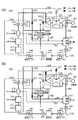
- (A) is a system block diagram of the power generation plant of embodiment of this invention
- (b) is a block diagram of the control apparatus of embodiment of this invention.
- (A) And (b) is explanatory drawing for demonstrating the open/close state of the on-off valve at the time of the operation of the power generation plant of embodiment of this invention.
- It is a block diagram of the heat storage apparatus of embodiment of this invention.
- (A) is an explanatory view for explaining changes in boiler load and generation of excess steam during FCB operation, and (b) is a table showing correspondence between boiler load and steam temperature.
- (A) is a graph showing the relationship between the manner in which the steam temperature changes and the operating mode
- (b) is a table showing the transition conditions depending on the operating mode and temperature.
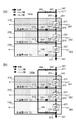
- (A) And (b) is explanatory drawing for demonstrating the open/close state of each on-off valve for every operation mode of the heat storage apparatus of embodiment of this invention.
- (A) And (b) is explanatory drawing for demonstrating the open/close state of each on-off valve for every operation mode of the heat storage apparatus of embodiment of this invention. It is explanatory drawing for demonstrating the design temperature of each heat exchanger of the boiler of a power generation plant. It is explanatory drawing for demonstrating an example of the connection at the time of heat recovery from the heat storage apparatus of embodiment of this invention. It is a block diagram of the heat storage apparatus of the modification of this invention.
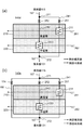
- (A) And (b) is explanatory drawing for demonstrating the open/close state of each on-off valve for every operation mode of the heat storage apparatus of the modified example of this invention.
- (A) And (b) is explanatory drawing for demonstrating the open/close state of each on-off valve for every operation mode of the heat storage apparatus of the modified example of this invention.
- (A) And (b) is a block diagram of the heat storage apparatus of the other modified example of this invention.
- (A) And (b) is a block diagram of the heat storage apparatus of the other modified example of this invention.
- (A) And (b) is a system block diagram of the modification of this invention. It is explanatory drawing for demonstrating the other connection example at the time of heat recovery from the heat storage apparatus of embodiment of this invention.
- the heat storage device of the present embodiment is used, for example, in the power generation plant 100 shown in FIG.
- FIG. 1A is a fluid system diagram of the power generation plant 100 of this embodiment.
- the power generation plant 100 of the present embodiment combusts a fuel and generates steam by the heat of the combustion, and a steam generator 110 drives the generator 101 by rotating a turbine using the steam generated by the boiler 110.
- the boiler 110 includes a economizer (ECO) 111, a furnace water cooling wall 112, a brackish water separator 113, a superheater 114, and a reheater 115.
- the superheater 114 may be provided in a plurality of stages from downstream to upstream.
- the steam turbine 120 includes a high pressure steam turbine (HPT) 121, an intermediate pressure steam turbine (IPT) 122, and a low pressure steam turbine (LPT) 123, each of which performs a predetermined work for driving the generator 101.
- HPT high pressure steam turbine
- IPT intermediate pressure steam turbine
- LPT low pressure steam turbine
- a condenser 131 On the water supply line 130, a condenser 131, a condensate pump 132, a low pressure water superheater (low pressure heater) 133, a deaerator 134, a water supply pump 135, and a high pressure water superheater (high pressure heater) 136. And are provided.
- the economizer 111 preheats the supplied water by heat exchange with the combustion gas.
- the water preheated in the economizer 111 passes through a furnace wall pipe (not shown) formed in the wall of the furnace water cooling wall 112 to generate a water-steam two-phase fluid.
- the water-steam two-phase fluid generated in the furnace water cooling wall 112 is sent to the brackish water separator 113 and separated into saturated steam and saturated water.
- the saturated steam is led to the superheater 114, and the saturated water is led to the condenser 131 through the first pipe 161.
- the saturated steam separated by the brackish water separator 113 is superheated by the superheater 114 by heat exchange with the combustion gas, and is introduced into the high-pressure steam turbine 121 via the main steam pipe 162.
- the steam that has performed a predetermined work in the high-pressure steam turbine 121 is guided to the reheater 115 via the low-temperature reheat steam pipe 163.
- the reheater 115 heats the steam that has performed a predetermined work in the high-pressure steam turbine 121.
- the steam superheated in the reheater 115 is supplied to the medium-pressure steam turbine 122 and the low-pressure steam turbine 123 via the high-temperature reheat steam pipe 164, where they perform their work and drive the generator 101.
- the main steam pipe 162 is provided with a first stop valve 176. Further, the high temperature reheat steam pipe 164 is provided with a second stop valve 177.
- the main steam pipe 162 and the low temperature reheat steam pipe 163 are connected to each other via a high pressure bypass steam pipe 165 having a first opening/closing valve 171.
- the steam that has finished its work in the low-pressure steam turbine 123 is introduced into the condenser 131 by the first exhaust steam pipe 166.
- the condensed water condensed in the condenser 131 passes through the low-pressure heater 133 by the condensate pump 132 together with the saturated water sent from the brackish water separator 113, and then is sent to the deaerator 134 to remove the gas component in the condensed water. To be done.
- the condensed water that has passed through the deaerator 134 is further pressurized by the water supply pump 135, then sent to the high-pressure heater 136 to be heated, and finally returned to the boiler 110.
- the power generation plant 100 includes a turbine bypass steam pipe 167 that branches from the high temperature reheat steam pipe 164 and guides the steam to the condenser 131 by bypassing the intermediate pressure steam turbine 122.
- the turbine bypass steam pipe 167 is provided with a turbine bypass opening/closing valve 172.
- the heat storage device 140 of this embodiment is arranged on the turbine bypass steam pipe 167.
- the thermal energy of the steam guided to the heat storage device 140 via the turbine bypass steam pipe 167 is stored in the heat storage device 140.
- the steam after heat exchange in the heat storage device 140 is introduced into the condenser 131.
- the turbine bypass steam pipe 167 may further include a second bypass steam pipe 168 that bypasses the heat storage device 140 and guides steam to the condenser 131.
- a third opening/closing valve 173 and a fourth opening/closing valve 174 are provided downstream of the branch point between the turbine bypass steam pipe 167 and the second bypass steam pipe 168, respectively.
- the turbine bypass steam pipe 167 is provided with a temperature sensor 181 for detecting the temperature of steam passing through the inside.
- the control device 150 receives an instruction from the outside (a control console 151 or the like placed in a power plant) or various types of devices including the temperature sensor 181 installed in the power plant 100.
- the opening and closing of each on-off valve is controlled according to the signal from the sensor.
- the power plant 100 of the present embodiment is generated in the boiler 110 without supplying the steam to the steam turbine 120 and the normal operation mode in which the normal operation mode in which the generator 101 is driven is performed. It has two kinds of operation modes: a heat storage operation mode in which the heat energy of the vapor is stored in the heat storage device 140.
- the control device 150 Upon receiving an operation command in the normal operation mode from the control console 151 or the like, the control device 150 outputs a close command to the turbine bypass on-off valve 172 and the first on-off valve 171 as shown in FIG. To do. As a result, the turbine bypass opening/closing valve 172 and the first opening/closing valve 171 are closed, steam and water circulate between the boiler 110, the steam turbine 120, and the water supply line 130, and the generator 101 is driven.
- the control device 150 when receiving the operation command in the heat storage operation mode, causes the turbine bypass opening/closing valve 172, the third opening/closing valve 173, and the first opening/closing valve 171 to open as shown in FIG. 2B. Is output. Further, it outputs a close command to the fourth on-off valve 174, the first stop valve 176 and the second stop valve 177. As a result, the turbine bypass opening/closing valve 172 and the third opening/closing valve 173 are opened, and the steam in the high temperature reheat steam pipe 164 is guided to the heat storage device 140.
- control device 150 of the present embodiment also controls the opening/closing of the opening/closing valve provided in each flow path of the heat storage device 140 described later. Details of the control will be described later.
- Heat storage device 140 of this embodiment will be described with reference to FIG.
- steam, water, and the like that recirculate in the power generation plant 100 are referred to as fluids when there is no need to distinguish them.
- the heat storage device 140 of the present embodiment includes a plurality of heat storage layers each made of a heat storage material having temperature characteristics (melting points) in different temperature ranges.
- a heat exchange unit is provided in each heat storage layer.
- a channel is provided in the heat storage device 140 so that the heat exchange units in each heat storage layer are connected in series and in parallel.
- the path through which the fluid passes is changed according to the temperature of the fluid supplied to the heat storage device 140. This efficiently accumulates heat.
- the path change is realized by a command from the control device 150 to an on-off valve provided for each fluid described later.
- the high temperature heat storage layer 210 (hereinafter, simply referred to as the high temperature layer 210) formed of a heat storage material having a temperature characteristic (melting point) in a temperature range (first temperature range) centered at 580°C. (Also referred to as ".”), a medium temperature heat storage layer 220 (medium temperature layer 220) composed of a heat storage material having a temperature characteristic in a temperature range (second temperature range) centered at 500°C, and a temperature range centered at 400°C.
- a low temperature heat storage layer 230 low temperature layer 230 formed of a heat storage material having a temperature characteristic in the (third temperature range) are provided.
- the heat storage device 140 includes a first flow path 241, a second flow path 242, and a third flow path 243 as flow paths used during heat storage.
- the first flow path 241 allows the fluid to pass through the high temperature layer 210, the intermediate temperature layer 220, and the low temperature layer 230 in this order.
- the fluid passing through the first flow path 241 exchanges heat in each heat storage layer and accumulates heat in each heat storage layer.
- the second flow path 242 allows the fluid to pass through the intermediate temperature layer 220 and the low temperature layer 230 in this order.
- the fluid passing through the second flow path 242 exchanges heat with each heat storage layer and accumulates heat in each heat storage layer.
- the third flow path 243 allows the fluid to pass only through the low temperature layer 230.
- the fluid passing through the third flow path 243 exchanges heat with the low temperature layer 230 and accumulates heat in the low temperature layer 230.
- Heat exchange is performed in the heat exchange section provided in each heat storage layer.
- the high temperature layer 210 has a high temperature heat exchange section 211
- the intermediate temperature layer 220 has a first intermediate temperature heat exchange section 221 and a second intermediate temperature heat exchange section 222
- the low temperature layer 230 The first low-temperature heat exchange section 231, the second low-temperature heat exchange section 232, and the third low-temperature heat exchange section 233 are provided in each.
- Each heat exchange section (high temperature heat exchange section 211, first medium temperature heat exchange section 221, second medium temperature heat exchange section 222, first low temperature heat exchange section 231, second low temperature heat exchange section 232, third The low temperature heat exchange section 233) exchanges heat with the inflowing fluid.
- each functions as a heat storage unit that stores heat energy in the heat storage layer.
- the heat energy stored in the heat storage layer is radiated.
- the first flow path 241 is branched from the turbine bypass steam pipe 167 at a branch point 271, and the high temperature heat exchange section 211, the first intermediate temperature heat exchange section 221 and the first low temperature heat exchange section 231 are connected in this order, and a confluence point 272 is obtained.
- the first flow path 241 allows the fluid flowing into the heat storage device 140 to pass through the high temperature heat exchange unit 211, the first intermediate temperature heat exchange unit 221, and the first low temperature heat exchange unit 231 in this order, and discharges the fluid from the heat storage device 140.
- the temperature of the supplied fluid is higher than the melting point of the high temperature layer 210, the heat energy of the fluid is stored in the high temperature layer 210, the intermediate temperature layer 220, and the low temperature layer 230 in this order.
- the second flow path 242 is branched from the turbine bypass steam pipe 167 at a branch point 271, the second intermediate temperature heat exchange section 222 and the second low temperature heat exchange section 232 are connected in this order, and the turbine bypass steam pipe is joined at a confluence point 272. 167.
- the second flow path 242 allows the fluid flowing into the heat storage device 140 to pass through the second intermediate-temperature heat exchange unit 222 and the second low-temperature heat exchange unit 232 in this order, and discharges from the heat storage device 140.
- the temperature of the supplied fluid is higher than the melting point of the intermediate temperature layer 220, the heat energy of the fluid is stored in the intermediate temperature layer 220 and the low temperature layer 230 in this order.
- the third flow path 243 is branched from the turbine bypass steam pipe 167 at a branch point 271 and is connected to the turbine bypass steam pipe 167 at a confluence point 272 via the third low temperature heat exchange section 233.
- the third flow path 243 allows the fluid flowing into the heat storage device 140 to pass through only the third low-temperature heat exchange section 233 and discharge from the heat storage device 140.
- the temperature of the supplied fluid is higher than the melting point of the low temperature layer 230, the heat energy of the fluid is stored in the low temperature layer 230.
- a high temperature on-off valve 251, an intermediate temperature on-off valve 252, and a low-temperature on-off valve 253 are provided on the inlet side of the heat storage device 140 of the first flow path 241, the second flow path 242, and the third flow path 243, respectively. These on-off valves are opened/closed in response to a command from the control device 150 issued according to the temperature of the fluid flowing in the turbine bypass steam pipe 167 upstream of the heat storage device 140.
- the control device 150 detects the temperature of the fluid flowing into the heat storage device 140 and opens/closes each on-off valve according to the temperature to control the inflow path of the fluid. For example, the opening and closing of the on-off valve is controlled according to the temperature of the inflowing fluid so that heat is stored in the heat storage layer of the heat storage material having a melting point that is lower than the temperature and has the closest melting point.
- the on-off valve control will be described later.
- the heat storage material used for each heat storage layer for example, a latent heat storage material that utilizes the latent heat of phase transformation of a substance can be used.
- the temperature characteristic of the heat storage layer is a characteristic determined based on the melting temperature (melting point) of this latent heat storage material.
- the heat storage material used for each heat storage layer may be an alloy-based material having a heat storage temperature (melting point) of more than 500°C. Further, the alloy-based material may have a structure containing ceramics or a metal.
- the latent heat storage microcapsules disclosed in WO 2017/200021 can be used.
- a heat storage material having a structure in which a latent heat storage material is included in each heat storage layer by means of ceramics, etc. it is possible to obtain a heat storage section that operates only by heat input/output, utilizing the phase transformation of the latent heat storage material. Since the melting temperature can be controlled by the composition at the time of manufacturing the latent heat storage material, the temperature range of the fluid can be set more finely.
- the heat storage material used for each heat storage layer is selected according to the temperature range of the heat energy stored in the heat storage device 140 and having a melting point within the temperature range. Further, the heat storage capacity of each heat storage layer is determined based on the estimated amount of surplus heat energy. As a result, the excess energy generated can be efficiently stored without wasting it. This also leads to optimization of capital investment.
- the heat storage device 140 As a flow path used at the time of heat recovery, a flow path that connects the heat exchange parts in the same heat storage layer is further provided.
- the heat storage device 140 includes a first heat recovery pipe 261 that passes through the high temperature heat exchange section 211 of the high temperature layer 210, a first intermediate temperature heat exchange section 221 and a second intermediate temperature heat exchange of the intermediate temperature layer 220.
- the first heat recovery pipe 261 recovers heat from only the high temperature layer 210 by allowing the fluid to pass through only the high temperature layer 210 during heat recovery.
- the second heat recovery pipe 262 recovers heat from only the intermediate temperature layer 220 by passing the fluid through only the intermediate temperature layer 220.
- the third heat recovery pipe 263 recovers heat from only the low temperature layer 230 by allowing the fluid to pass through only the low temperature layer 230.
- the heat storage device 140 of the present embodiment at the time of heat recovery, it is possible to individually and independently recover the heat energy of a plurality of different temperatures according to the melting points in each heat storage layer. Then, the recovered thermal energy of different temperatures can be provided to the users according to the required temperatures. That is, according to the heat storage device 140 of the present embodiment, it is possible to properly use heat according to the application.
- FCB Full Cut Back
- the load on the boiler 110 is, for example, 5%. It is narrowed down to the extent. Even if the operation of the mill is stopped in this way, the steam generated by the boiler 110 continues to be generated as excess energy, as indicated by the shaded area.
- FIG. 4B shows changes in the temperature of the steam passing through the turbine bypass steam pipe 167 when the load of the boiler 110 is gradually reduced.
- the heat quantity of the surplus energy that continues to be generated after the system is cut off is stored in the heat storage device 140.
- each on-off valve is controlled to open/close according to the temperature of the steam flowing through the turbine bypass steam pipe 167, and heat is stored in the heat storage layer of the heat storage material having a melting point which is lower than the temperature and has the closest melting point.
- the heat energy stored in the heat storage device 140 is recovered and used to operate the boiler 110.
- the design temperature of each heat exchanger furnace water cooling wall 112, brackish water separator 113, superheater 114 included in the boiler 110, a part of the fluid supplied to the heat exchanger is branched and designed. Heat energy is recovered from the heat storage layer of the heat storage material having a melting point corresponding to the temperature and returned to the inside of the boiler 110.
- control device 150 When the control device 150 receives the system cutoff instruction, it narrows down the load on the boiler 110 and outputs an open command to the turbine bypass on-off valve 172 to open the turbine bypass on-off valve 172. As a result, the fluid generated in the boiler 110 is guided to the heat storage device 140 via the turbine bypass steam pipe 167.
- control device 150 detects the temperature of the fluid flowing through the turbine bypass steam pipe 167, and controls the opening/closing of the high temperature opening/closing valve 251, the intermediate temperature opening/closing valve 252, and the low temperature opening/closing valve 253 according to the detected temperature.
- the temperature range of each heat storage layer is determined according to the bypass steam temperature after a lapse of a predetermined time after the system is shut off. Furthermore, regarding the heat storage capacity of each heat storage layer, the amount of surplus energy after the passage of each time is set to a capacity capable of storing heat.
- the latent heat storage material having a melting point of 580° C. when used for the high temperature layer 210, the latent heat storage material having a melting point of 500° C. is used for the intermediate temperature layer 220, and the latent heat storage material having a melting point of 400° C. is used for the low temperature layer 230.
- the opening/closing instruction of each on-off valve by the control device 150 will be described.
- the second bypass steam pipe 168 will also be described.
- the temperature thresholds T1 and T2 are set to values that allow a margin of about 10° C. for the melting point of each latent heat storage material.
- T1 is 590°C and T2 is 510°C.
- the control device 150 of the present embodiment controls the opening and closing of each on-off valve of the heat storage device 140 each time the turbine bypass steam temperature reaches the temperature threshold value.
- the operation of each on-off valve in different opening/closing modes is called an operation mode. Therefore, the controller 150 shifts the operation mode every time the turbine bypass steam temperature reaches the temperature threshold value.
- the operation mode 1 is an operation mode when the bypass steam temperature T is equal to or higher than the first temperature threshold value T1.
- the operation mode 2 is an operation mode when the bypass steam temperature T is lower than the first temperature threshold T1 and higher than or equal to the second temperature threshold T2.
- Operation mode 3 is an operation mode when the bypass steam temperature T is lower than the second temperature threshold value T2 and higher than or equal to the third temperature threshold value T3.
- the operation mode 4 is an operation mode when the bypass steam temperature T is lower than the third temperature threshold value T3.
- the operation mode 4 includes, for example, an emergency such as a failure of the power generation plant 100.
- the control device 150 opens only the high temperature on-off valve 251 and opens the other on-off valves 252, 253, as shown in FIG. 174 is closed.
- the fluid flowing into the heat storage device 140 flows in the order of the high temperature heat exchange section 211, the first intermediate temperature heat exchange section 221, and the first low temperature heat exchange section 231, as indicated by the thick line in the figure.
- the fluid whose temperature has dropped due to heat exchange in the high temperature heat exchange section 211 flows into the first intermediate temperature heat exchange section 221.
- the fluid that has undergone heat exchange in the first medium-temperature heat exchange section 221 and has its temperature further lowered flows into the first low-temperature heat exchange section 231.
- the fluid whose temperature is further lowered by the heat exchange in the first low temperature heat exchange section 231 is discharged from the heat storage device 140 to the condenser 131 via the turbine bypass steam pipe 167.
- the control device 150 opens only the medium temperature on-off valve 252 and the other on-off valves 251 as shown in FIG. 6(b). 253 and 174 are closed. As a result, the fluid flowing into the heat storage device 140 flows in the order of the second intermediate temperature heat exchange section 222 and the second low temperature heat exchange section 232, as indicated by the thick line in this figure.
- the fluid whose temperature has dropped due to heat exchange in the second medium temperature heat exchange section 222 flows into the second low temperature heat exchange section 232. Then, the fluid whose temperature has been further lowered by the heat exchange in the second low temperature heat exchange section 232 is discharged from the heat storage device 140 to the condenser 131 via the turbine bypass steam pipe 167.
- the control device 150 opens only the low temperature on-off valve 253 and opens the other on-off valves 251 as shown in FIG. , 252, 174 are closed.
- the fluid flowing into the heat storage device 140 flows into the third low temperature heat exchange section 233, as indicated by the thick line in this figure.
- the fluid whose temperature has dropped due to heat exchange in the third low temperature heat exchange section 233 is discharged from the heat storage device 140 to the condenser 131 via the turbine bypass steam pipe 167.
- the control device 150 opens only the fourth opening/closing valve 174 and opens the other opening/closing valves 251, 252, as shown in FIG. 7B. 253 is closed.
- the fluid in the turbine bypass steam pipe 167 is discharged to the condenser 131 via the second bypass steam pipe 168, and the fluid does not flow into the heat storage device 140, as indicated by the thick line in this figure.
- the heat storage device 140 of this embodiment can store heat energy in a plurality of temperature ranges. Therefore, even when heat is recovered from the heat storage device 140, it can be recovered for each temperature range and provided to the user.
- the heat energy recovered from each heat storage layer is supplied to each heat exchanger of the boiler 110 according to the design temperature thereof.
- Fig. 8 shows an example of the design temperature of each heat exchanger of the boiler 110.
- the boiler 110 shall be provided with the primary superheater 114a and the secondary superheater 114b.
- the inlet side and the outlet side design temperatures of the furnace water cooling wall 112, the primary superheater 114a, and the secondary superheater 114b are 330° C., 430° C., 430° C., 470° C., 460° C., 560° C., respectively. °C.
- a part of the fluid supplied to the furnace water cooling wall 112 is heated by passing through the low temperature layer 230 and supplied to the outlet side of the furnace water cooling wall 112. Further, a part of the fluid supplied to the primary superheater 114a is heated by passing through the intermediate temperature layer 220, and is supplied to the outlet side thereof. Further, a part of the fluid supplied to the secondary superheater 114b is heated by passing through the high temperature layer 210 and supplied to the outlet side thereof.
- the inlet side of the third heat recovery pipe 263 for recovering heat energy from the low temperature layer 230 of the heat storage device 140 is connected to the inlet side pipe of the furnace water cooling wall 112. Further, the outlet side of the third heat recovery pipe 263 is connected to the outlet side pipe of the furnace water cooling wall 112.
- the inlet side of the second heat recovery pipe 262 for recovering heat energy from the intermediate temperature layer 220 is connected to the inlet side pipe of the primary superheater 114a.
- the outlet side of the second heat recovery pipe 262 is connected to the outlet side pipe of the primary superheater 114a.
- the inlet side of the first heat recovery pipe 261 for recovering heat energy from the high temperature layer 210 is connected to the piping on the inlet side of the secondary superheater 114b.
- the outlet side of the first heat recovery pipe 261 is connected to the outlet side pipe of the secondary superheater 114b.
- the power plant 100 includes the heat storage device 140 having a plurality of heat storage layers each formed of a latent heat storage material having a different melting point. Then, when the surplus energy is generated, the heat energy corresponding to the melting point of the latent heat storage material forming the heat storage layer is stored in each heat storage layer of the heat storage device 140.
- surplus energy can be stored independently for each temperature zone. Therefore, when recovering the heat from the heat storage device 140, the heat can be recovered from the heat storage layer that stores the heat energy according to the temperature required by the heat exchanger of the use destination, and the surplus energy can be efficiently used. For example, by utilizing this surplus energy at the time of system restoration after FCB, it is possible to provide optimum heat energy to each heat exchanger of the boiler 110, and it is possible to quickly start up.
- a latent heat storage material that uses the latent heat of phase transformation of a substance is used as the heat storage material of each heat storage layer.
- a heat storage unit capable of high-density heat storage which operates only by heat input/output.
- a high heat storage temperature can be realized by using an alloy-based material having a high melting point as the latent heat storage material.
- high temperature fluid such as turbine bypass steam can be stored at the high temperature as it is.
- a flow path is provided so as to flow into the heat storage layer of the heat storage material having a melting point closest to and lower than the temperature. Therefore, it is possible to realize heat storage for each of a plurality of temperature ranges with a simple configuration.
- each flow path in the heat storage device 140 is provided so that the fluid that has passed through the heat storage layer also passes through the heat storage layer, if there is a heat storage layer composed of a heat storage material having the next highest melting point.
- a heat storage layer composed of a heat storage material having the next highest melting point.
- a heat storage layer having sufficient performance for each temperature range of the fluid is arranged for each temperature range of the fluid.
- the temperature range of each heat storage layer is determined according to the bypass steam temperature after a lapse of a predetermined time after the system interruption. Further, the heat storage capacity of each heat storage layer is determined according to the amount of surplus energy after the passage of time.
- the heat storage device 140 recovers the heat of the fluid without exhaustion, so the temperature of the fluid discharged from the heat storage device 140 to the condenser 131 becomes low. .. Therefore, the amount of heat returned to the condenser 131 can be suppressed.
- the heat quantity of excess steam is large.
- the conventional power plant 100 when the FCB function is provided, all the generated excess steam is returned to the condenser 131. Therefore, not only is there a large amount of waste, but also a large receiving capacity is required on the condenser 131 side. Large-scale construction is required to achieve a large capacity of the condenser 131.
- most of the heat quantity of the fluid returned to the condenser 131 is stored in the heat storage device 140, so the performance of the condenser 131 is the condenser 131 used when the FCB function is not provided. Can be approximately the same as. Therefore, the equipment cost can be suppressed.
- the power generation plant 100 including the heat storage device 140 of the present embodiment can efficiently store heat during FCB, and can also efficiently recover the stored heat energy when returning to the system. Further, the heat storage energy stored in the heat storage device 140 can be utilized not only when the system is restored after the FCB but also when the power is normally started or when the load of the power generation plant 100 is rapidly increased. As a result, the start-up time and the load rise time can be shortened.
- a rapid load increase is, for example, a case where a load change that is faster than the start/load change/stop during normal operation is required.
- the system side requests a load increase that is higher than the normal startup, such as when the system is restored after it becomes unstable.
- the rate of increase is 5%/min or more for the boiler 110, and 10 to 20%/min or more for the gas turbine.
- the load change rate is a device that constitutes the power generation plant 100 and exceeds a load change rate defined by a limit corresponding to a change in heat quantity of a device other than the steam turbine 120, or a load change that the boiler 110 cannot meet the system requirements. Includes cases where required.
- the heat storage device 140 is arranged on the turbine bypass steam pipe 167 having the turbine bypass opening/closing valve 172.
- the switching to the heat storage operation mode can be immediately performed only by instructing the turbine bypass on-off valve 172 to open and close.
- the switching process when the system is forced to be shut off such as FCB can be easily performed, and the generated surplus energy can be easily recovered.
- the heat storage device 140 of the present embodiment for starting and stopping a steam power generation plant in DSS (Daily Start & Stop), it is possible to shorten the starting and stopping time. Further, by using the heat storage device 140 of the present embodiment, even when the steam power generation plant and the renewable energy power generation plant are used together, it is possible to level the fluctuation of the power supply amount derived from the renewable energy in total. As a result, the number of occurrences of a state in which the overall power supply amount exceeds the demand of the system is reduced.
- the heat storage device 140 is configured such that the heat storage units that are the heat exchange units of the heat storage layers are connected in series and in parallel by the internal flow paths, but the configuration is not limited to this. It suffices that the heat can be stored in the optimum heat storage layer according to the temperature of the fluid flowing into the heat storage device 140, and the heat can be stored in a mode that can be used for each temperature during heat dissipation. A modified example of the heat storage device 140 will be described below.
- FIG. 10 shows another example of the heat storage device 140 of the present embodiment (hereinafter, referred to as heat storage device 140a).
- heat storage device 140a a case where three heat storage layers of a high temperature layer 210, an intermediate temperature layer 220, and a low temperature layer 230 are provided will be described as an example.
- the heat exchangers of each heat storage layer are connected in series.
- the heat storage device 140a includes a high temperature heat exchange section 211, a first intermediate temperature heat exchange section 221, a first low temperature heat exchange section 231, a first flow path 241, a second flow path 342, and a third flow path 343, High temperature open/close valve 251, first medium temperature open/close valve 352, low temperature open/close valve 353, second intermediate temperature open/close valve 354, first heat recovery pipe 261, second heat recovery pipe 262, and third heat recovery pipe 263.
- the high temperature heat exchange section 211, the first medium temperature heat exchange section 221, and the first low temperature heat exchange section 231 are the same as the heat storage device 140, respectively. Further, the first flow path 241 and the high temperature on-off valve 251 are also similar to the heat storage device 140. Hereinafter, the configuration different from that of the heat storage device 140 will be mainly described.
- the second flow path 342 branches from the turbine bypass steam pipe 167 at a branch point 271, bypasses the high temperature heat exchange section 211, and merges with the first flow path 241 at a downstream junction point 375 of the high temperature heat exchange section 211.
- the second flow path 342 allows the fluid flowing into the heat storage device 140a to pass through the first intermediate temperature heat exchange unit 221 and the first low temperature heat exchange unit 231 in that order, and discharges the fluid from the heat storage device 140a.
- the third flow path 343 branches from the second flow path 342 at a branch point 372 downstream of the first middle temperature heat on-off valve 352, bypasses the first middle temperature heat exchange section 221, and passes through the first middle temperature heat exchange section 221. It joins the first flow path 241 at the downstream joining point 376.
- the third flow path 343 allows the fluid flowing into the heat storage device 140a to pass only through the first low-temperature heat exchange section 231, and discharges the fluid from the heat storage device 140a.
- a low temperature on-off valve 353 is provided.
- the control device 150 outputs an opening/closing command to each on-off valve according to the temperature of the fluid flowing in the turbine bypass steam pipe 167 on the upstream side of the heat storage device 140a.
- the control device 150 determines that the temperature of the fluid flowing upstream of the heat storage device 140 in the turbine bypass steam pipe 167 is equal to or higher than the first temperature threshold T1.
- the high temperature on-off valve 251 is opened and the first medium temperature on-off valve 352 is closed.
- the high temperature on-off valve 251 is closed and the first medium temperature on-off valve 352 is opened.
- the second medium temperature on-off valve 354 is opened and the low temperature on-off valve 353 is closed.
- the second medium temperature on-off valve 354 is closed and the low temperature on-off valve 353 is opened.
- the control of the on-off valve by the control device 150 in each of the operation modes 1 to 4 in this case will be described with reference to FIGS. 11(a) to 12(b).
- the operation including the second bypass steam pipe 168 and the fourth on-off valve 174 will be described.
- the second bypass steam pipe 168 branches at the branch point 373 on the third flow path 343, bypasses the first low temperature heat exchange section 231, and at the confluence point 272, the first flow. It joins the path 241 (turbine bypass steam pipe 167).
- the control device 150 controls the opening/closing of each on-off valve so that the fluid passes through the first flow path 241 in the operation mode 1, that is, when the bypass steam temperature T is T1 or more. That is, as shown in FIG. 11A, the control device 150 outputs a command signal to open only the high temperature opening/closing valve 251 and close the other opening/closing valves 174, 352, 353, 354. As a result, the fluid flowing into the heat storage device 140a flows in the order of the high temperature heat exchange part 211, the first medium temperature heat exchange part 221, and the first low temperature heat exchange part 231 as shown by the thick line, and is discharged from the heat storage device 140a. ..
- the control device 150 controls opening/closing of each on-off valve so that the fluid passes through the second flow path 342. That is, as shown in FIG. 11B, the control device 150 opens the first medium temperature on-off valve 352 and the second medium temperature on-off valve 354, and closes the other on-off valves 251, 353, 174. Output a signal. As a result, the fluid flowing into the heat storage device 140a flows in the order of the first medium temperature heat exchange unit 221 and the first low temperature heat exchange unit 231 as shown by the thick line, and is discharged from the heat storage device 140a.
- the control device 150 controls opening/closing of each on-off valve so that the fluid passes through the third flow path 243. That is, as shown in FIG. 12A, the controller 150 outputs a command signal to open the first medium temperature on-off valve 352 and the low temperature on-off valve 353 and close the other on-off valves 251, 354, 174. To do. As a result, the fluid flowing into the heat storage device 140a passes through only the first low temperature heat exchange section 231 and is discharged from the heat storage device 140, as indicated by the thick line.
- the bypass steam is controlled so as to bypass each heat storage layer of the heat storage device 140a and pass through the second bypass steam pipe 168. That is, as shown in FIG. 12B, the control device 150 sends a command signal to open the first medium temperature on-off valve 352 and the fourth on-off valve 174 and close the other on-off valves 251, 354, 353. Output. As a result, the fluid flowing into the heat storage device 140a is guided to the condenser 131 without releasing heat to the heat storage device 140a, as indicated by the thick line.
- FIG. 13A shows a configuration example of the heat storage device 140b in this case.
- the first flow path 241 passes through only the high temperature heat exchange section 211 and discharges the fluid after heat exchange from the heat storage device 140.
- the second flow path 242 passes only through the second intermediate temperature heat exchange section 222, and discharges the fluid after heat exchange from the heat storage device 140.
- the third flow path 243 passes only through the third low temperature heat exchange section 233 and discharges the fluid after heat exchange from the heat storage device 140.
- the same effect as the heat storage device 140 can be realized with a simple configuration.
- each heat exchange section of the heat storage device 140 may be provided in each heat storage layer, and may be connected in series and in parallel as in the above embodiment. That is, in each flow path, each heat storage layer may share the heat exchange unit.
- FIG. 13B shows a configuration example of the heat storage device 140c in this case.
- the first flow path 241 passes through the high temperature heat exchange section 211, the first medium temperature heat exchange section 221, and the first low temperature heat exchange section 231. Further, the second flow path 242 passes through the first intermediate temperature heat exchange section 221 and the first low temperature heat exchange section 231.
- the third flow path 243 passes through the first low temperature heat exchange section 231. That is, the fluid flows into the first intermediate temperature heat exchange section 221 through the first flow channel 241 and the second flow channel 242. Further, the fluid flows into the first low temperature heat exchange section 231 through the first flow channel 241, the second flow channel 242 and the third flow channel 243.
- FIG. 14A shows an example of the heat storage device in the case where the heat storage layers are two layers and the heat exchange units in each heat storage layer are connected in parallel.
- the heat storage device 140d shown in FIG. 14A is provided in the high temperature layer 210 and performs high temperature heat exchange part 211 for heat exchange, and the second intermediate temperature heat exchange part 222 provided in the intermediate temperature layer 220 for heat exchange. And in addition, the fluid flowing into the heat storage device 140d is branched at a branch point 271 upstream of the high temperature heat exchange portion 211 of the first flow path 241 that passes through the high temperature heat exchange portion 211 and is discharged from the heat storage device 140d.
- the second flow path 242 is configured to allow the fluid flowing into the heat storage device 140d to pass through the second intermediate temperature heat exchange unit 222 and be discharged from the heat storage device 140d.
- a high-temperature on-off valve 251 that is provided on the first flow path 241 and controls the inflow of the fluid to the high-temperature heat exchange section 211, and a fluid that is provided on the second flow path 242 and that flows to the second intermediate-temperature heat exchange section 222.
- a medium temperature on-off valve 252 for controlling the inflow of the gas.
- the high temperature on-off valve 251 is in the open state when the temperature of the fluid is equal to or higher than the predetermined first temperature threshold T1 according to the instruction from the control device 150, and the medium-temperature on-off valve 252 changes the temperature of the fluid. When it is less than the first temperature threshold value T1, the open state is established.
- control of the on-off valve by the control device 150 when the power plant 100 includes the second bypass steam pipe 168 and the fourth on-off valve 174 will be described using the heat storage device 140e of FIG. 14(b).
- the configuration of the heat storage device 140e shown in FIG. 14B is the same as that of the heat storage device 140d.
- the second bypass steam pipe 168 branches from the branch point 271 and joins with the turbine bypass steam pipe 167 at the joining point 272. Further, the second bypass steam pipe 168 is provided with a fourth on-off valve 174.
- the high temperature on-off valve 251 is in the open state when the temperature of the fluid is equal to or higher than the predetermined first temperature threshold T1 according to a command from the control device 150, and the medium temperature on-off valve is opened. 252 is in the open state when the temperature of the fluid is lower than the first temperature threshold value T1.
- the medium-temperature on-off valve 252 is in the closed state according to the command from the control device 150 even if the temperature of the fluid is less than the first temperature threshold T1 but less than the second temperature threshold T2. .
- the control device 150 opens the fourth opening/closing valve 174 and causes the fluid flowing through the turbine bypass steam pipe 167 to store the fluid in the heat storage device 140e (the high temperature heat exchange unit 211 and the first heat exchange unit 211). (2) Bypasses the intermediate temperature heat exchange section 222).
- Fig. 15(a) shows an example of the heat storage device in the case where the heat storage layers are two layers and the heat exchange units in each heat storage layer are connected in series.
- the heat storage device 140f shown in FIG. 15(a) is provided in the high temperature layer 210 and performs high temperature heat exchange section 211 for heat exchange, and the first intermediate temperature heat exchange section 221 provided in the intermediate temperature layer 220 for heat exchange. And Further, the fluid flowing into the heat storage device 140f passes through the high temperature heat exchange part 211 and the first medium temperature heat exchange part 221 in this order and is discharged from the heat storage device 140f, and the high temperature heat exchange of the first flow channel 241.
- a path 342 Further, a high temperature on-off valve 251 which is provided on the first flow path 241 and controls the inflow of the fluid to the high temperature heat exchange section 211, and a fluid which is provided on the second flow path 242 and which flows to the first intermediate temperature heat exchange section 221.
- a first medium temperature on-off valve 352 for controlling the inflow of the gas.
- the high temperature on-off valve 251 is in the open state, and the first medium temperature on-off valve 352 controls the fluid temperature.
- the open state is established.
- control of the on-off valve by the control device 150 when the power plant 100 includes the second bypass steam pipe 168 and the fourth on-off valve 174 will be described using the heat storage device 140g of FIG. 15B.
- the configuration of the heat storage device 140g illustrated in FIG. 15B is substantially the same as that of the heat storage device 140f.
- the second bypass steam pipe 168 branches from the branch point 372 downstream of the first medium temperature on-off valve 352 of the second flow path 342, and is connected to the turbine bypass steam pipe 167 at the confluence point 272.
- the second bypass steam pipe 168 is provided with a fourth on-off valve 174.
- a second intermediate temperature switching valve 354 is provided downstream of the branch point 372 of the second flow path 342.
- the high temperature on-off valve 251 is in the open state and the first medium temperature.
- the on-off valve 352 is in the open state when the temperature of the fluid is lower than the first temperature threshold value T1.
- the second medium temperature on-off valve 354 In response to a command from the control device 150, the second medium temperature on-off valve 354 is in an open state when the fluid temperature is equal to or higher than the second temperature threshold T2, and the fourth on-off valve 174 causes the fluid temperature to be the second temperature threshold T2. If it is less than, it is in the open state.
- the heat storage device 140 can optimize the number (size) of heat storage layers and the route according to the required temperature and the amount of steam. Heat can be stored for each temperature level with a simple configuration in which a heat exchange unit is installed in each heat storage layer and the steam path is controlled by opening and closing the on-off valve.
- the heat storage device 140 acquires heat energy from the fluid passing through the turbine bypass steam pipe 167 and stores the heat energy.
- the heat storage target is not limited to the heat energy of this fluid.
- the heat energy of saturated water returned from the brackish water separator 113 to the condenser 131 may be stored.
- a system diagram of the power generation plant 100 in this case is shown in FIG.
- a heat storage pipe 161a is provided in the first pipe 161 for returning saturated water from the brackish water separator 113 to the condenser 131.
- the heat storage pipe 161 a branches from the first pipe 161 and passes through the heat storage device 140 to join the first pipe 161.
- the heat storage pipe 161a is provided with a fifth opening/closing valve 175 on the upstream side of the heat storage device 140.
- the fifth on-off valve 175 is an on-off valve for controlling whether saturated water supplied from the brackish water separator 113 is returned to the condenser 131 via the heat storage device 140 or directly returned.
- the control device 150 issues a command to open the saturated water when it flows into the heat storage device 140.
- the heat storage device that stores the heat energy of the saturated water returned from the brackish water separator 113 to the condenser 131 is independent of the heat storage device 140 provided on the turbine bypass steam pipe 167. May be An example of piping in this case is shown in FIG.
- the heat storage device 141 is provided, for example, on the first pipe 161 as shown in this figure.
- a bypass flow path for returning the saturated water to the condenser 131 by bypassing the heat storage device 141 may be further provided.
- the saturated water returned from the brackish water separator 113 to the condenser 131 is also configured to store heat, whereby excess heat energy generated in the system can be stored without exhaustion. it can. Then, the stored heat energy can be used when the system is restored.
- the thermal energy stored in the heat storage device 140 is supplied to the heat exchanger of the boiler 110 corresponding to the temperature range of the heat storage layer for each heat storage layer, so that the boiler 110 rapidly increases. It efficiently supports energy supply when the load rises.
- the method of recovering heat from the heat storage device 140 is not limited to this.
- the fluid may be passed layer by layer from the low temperature layer 230, and the entire heat energy stored in the heat storage device 140 may be recovered and then returned to the system of the power generation plant 100.
- the recovery destination of the fluid after recovering the heat energy is, for example, the main steam pipe 162.
- the fluid to the heat storage device 140 is supplied from, for example, the water supply line 130.
- the fourth heat recovery pipe 264 that connects the water supply line 130 and the main steam pipe 162 is provided, and the heat storage device 140 is disposed on the fourth heat recovery pipe 264.
- the water introduced into the heat storage device 140 is heated in the order of the low temperature layer 230, the intermediate temperature layer 220, and the high temperature layer 210.
- high-temperature, high-pressure steam is generated only in the heat storage device 140 and can be directly fed to the high-pressure steam turbine 121.
- the low temperature reheat steam pipe 163 may be used as the return destination of the fluid after heat energy recovery in the heat storage device 140 during high load operation.
Landscapes
- Engineering & Computer Science (AREA)
- Mechanical Engineering (AREA)
- General Engineering & Computer Science (AREA)
- Physics & Mathematics (AREA)
- Thermal Sciences (AREA)
- Chemical & Material Sciences (AREA)
- Combustion & Propulsion (AREA)
- Engine Equipment That Uses Special Cycles (AREA)
- Control Of Eletrric Generators (AREA)
Abstract
Provided is technology to efficiently store and use, in a plurality of different temperature ranges, excess energy generated at a power generation plant. A heat storage device 140 that has a plurality of heat storage units to recover and accumulate heat from a fluid passing through a channel provided therein is characterized by comprising a first heat storage unit that has temperature characteristics in a first temperature range, a second heat storage unit that has temperature characteristics in a second temperature range, which is a lower temperature range than the first temperature range, a first channel 241 that causes inflowing fluid to pass through the first heat storage unit and the second heat storage unit in order, a second channel 242 that causes the inflowing fluid to bypass the first heat storage unit and pass through the second heat storage unit, a first on-off valve 251 that is provided on the first channel 241, and a second on-off valve 252 that is provided on the second channel 242, wherein the first on-off valve 251 is in an open state if the fluid temperature is at a first temperature threshold or higher and the second on-off valve 252 is in an open state if the fluid temperature is less than the first temperature threshold.
Description
本発明は、各種燃料の燃焼熱を利用する汽力発電プラントに関し、特に、蒸気の熱の一部を熱エネルギとして貯蔵(蓄熱)し、必要に応じて貯蔵(蓄熱)した熱エネルギを発電プラントに供給する技術に関する。
The present invention relates to a steam power generation plant that uses combustion heat of various fuels, and in particular, a part of heat of steam is stored (heat storage) as heat energy, and the stored heat energy (heat storage) is stored in a power generation plant as needed. Regarding supply technology.
特許文献1には、複数の蓄熱槽を並列に接続し、蓄熱、放熱を行う太陽光発電システムが開示されている。
Patent Document 1 discloses a solar power generation system in which a plurality of heat storage tanks are connected in parallel to store and radiate heat.
また、温度特性の温度域が異なる2つの蓄熱部を有する蓄熱装置に熱エネルギを蓄熱し、発電プラントの運転時に用いる技術がある。例えば、特許文献2には、それぞれ蓄熱媒体が異なる高温蓄熱装置と低温蓄熱装置とを、直列に接続した蓄熱部を有する太陽熱発電プラントが開示されている。特許文献2に開示のシステムでは、蓄熱運転モード時は、過熱蒸気の一部を、高温蓄熱装置、低温蓄熱装置の順に蓄熱する。一方、放熱運転モード時は、給水ポンプから給水された水が、低温蓄熱装置、高温蓄熱装置の順に流れて各蓄熱装置に蓄熱されている熱を回収し、過熱蒸気が生成され、蒸気タービンに供給される。
There is also a technology that stores heat energy in a heat storage device that has two heat storage units that have different temperature ranges of temperature characteristics and that is used during operation of a power plant. For example, Patent Literature 2 discloses a solar thermal power generation plant having a heat storage unit in which a high-temperature heat storage device and a low-temperature heat storage device each having a different heat storage medium are connected in series. In the system disclosed in Patent Document 2, part of the superheated steam is stored in the high temperature heat storage device and the low temperature heat storage device in this order in the heat storage operation mode. On the other hand, in the heat radiation operation mode, the water supplied from the water supply pump flows in the order of the low-temperature heat storage device and the high-temperature heat storage device to recover the heat stored in each heat storage device, and superheated steam is generated to the steam turbine. Supplied.
特許文献1に開示の技術によれば、蓄熱時、飽和蒸気は、太陽熱発電システムから、各蓄熱槽に1つずつ順に供給される。具体的には、各蓄熱槽の温度をモニタし、熱媒体の飽和温度に達すると、蓄熱槽を切り替える。また、放熱時も同様に、各蓄熱槽に1つずつ順に水を供給し、熱交換により飽和蒸気を含む気液二相流体を生成し、太陽熱発電システムに供給する。しかしながら、蓄熱層ではコンクリート等の固体蓄熱材による顕熱蓄熱が行われるため、放熱に伴い蓄熱材の温度も低下し、気液二相流体の温度制御が困難である。
According to the technique disclosed in Patent Document 1, when storing heat, saturated steam is sequentially supplied from the solar thermal power generation system to each heat storage tank one by one. Specifically, the temperature of each heat storage tank is monitored, and when the saturation temperature of the heat medium is reached, the heat storage tank is switched. Similarly, at the time of heat radiation, water is sequentially supplied to each heat storage tank one by one to generate a gas-liquid two-phase fluid containing saturated steam by heat exchange and supply it to the solar thermal power generation system. However, in the heat storage layer, sensible heat storage is performed by a solid heat storage material such as concrete, so that the temperature of the heat storage material also decreases with heat dissipation, making it difficult to control the temperature of the gas-liquid two-phase fluid.
特許文献2に開示の技術によれば、高温、低温の2種の蓄熱装置を備えているものの、高温蓄熱装置は溶融塩による顕熱蓄熱であるため、特許文献1と同様、蓄熱した熱を利用する際に、溶融塩の放射による温度低下に伴い蒸気の出力温度も低下する。また、高温、低温の2種の蓄熱装置が直列に接続されているため、流入する蒸気の温度が低下する場合、蒸気が逆に高温蓄熱装置から吸熱してしまい効率的に蓄熱できない。
According to the technique disclosed in Patent Document 2, although two types of heat storage devices of high temperature and low temperature are provided, since the high temperature heat storage device is sensible heat storage by molten salt, the stored heat is stored as in Patent Document 1. When used, the output temperature of the steam also decreases with the temperature decrease due to the radiation of the molten salt. In addition, since two types of heat storage devices, high temperature and low temperature, are connected in series, when the temperature of the inflowing steam decreases, the steam conversely absorbs heat from the high temperature heat storage device and cannot efficiently store heat.
潜熱蓄熱は、物質の相変態潜熱を利用したものであり、蓄熱材の融点に応じた一定温度の熱を蓄熱し、かつ、供給できる点に特徴がある。しかしながら、一般に、発電プラントでは、構成機器ごとに異なる温度域の水および蒸気が流れているため、特許文献2に開示の技術では、1つの温度域に温度特性を有する蓄熱材しか用いられておらず、複数の異なる温度域の水および蒸気を発電プラントの各機器に供給できない。また、1種類の潜熱蓄熱材しか使用しないために、蓄熱量は潜熱蓄熱材の温度特性によって決定され、効率的に蓄熱できない。
Latent heat storage uses latent heat of phase transformation of a substance, and is characterized in that it can store and supply heat at a constant temperature according to the melting point of the heat storage material. However, in general, in a power plant, water and steam in different temperature ranges flow for each component device, and thus the technique disclosed in Patent Document 2 uses only a heat storage material having temperature characteristics in one temperature range. Therefore, water and steam in different temperature ranges cannot be supplied to each device of the power plant. Further, since only one type of latent heat storage material is used, the amount of heat storage is determined by the temperature characteristics of the latent heat storage material, and heat cannot be stored efficiently.
本発明は、上記事情に鑑みてなされたもので、発電プラントで発生する余剰エネルギを複数の異なる温度域で効率よく貯蔵、利用する技術を提供することを目的とする。
The present invention has been made in view of the above circumstances, and an object thereof is to provide a technique for efficiently storing and using surplus energy generated in a power plant in a plurality of different temperature ranges.
本発明は、内部に設けられた流路を通過する流体から熱を回収して蓄積する複数の蓄熱部を有する蓄熱装置であって、前記蓄熱部は、第一温度域に温度特性を持つ第一蓄熱部と、前記第一温度域より低い温度域である第二温度域に温度特性を持つ第二蓄熱部と、を備え、前記流路は、当該蓄熱装置に流入する前記流体を、前記第一蓄熱部、前記第二蓄熱部の順に通過させて当該蓄熱装置から排出する第一流路と、前記第一流路の前記第一蓄熱部の上流の第一分岐部で分岐し、当該蓄熱装置に流入する前記流体を、前記第一蓄熱部をバイパスして前記第二蓄熱部を通過させて当該蓄熱装置から排出する第二流路と、前記流路への前記流体の流入を制御する開閉弁と、を備え、前記開閉弁は、前記第一流路上に設けられ、前記第一蓄熱部への前記流体の流入を制御する第一開閉弁と、前記第二流路上に設けられ、前記第二蓄熱部への前記流体の流入を制御する第二開閉弁と、を備え、前記第一開閉弁は、前記流体の温度が前記第一温度域により定められた第一温度閾値以上である場合、開状態となり、前記第二開閉弁は、前記流体の温度が前記第一温度閾値未満である場合開状態となることを特徴とする。
The present invention is a heat storage device having a plurality of heat storage units for recovering and accumulating heat from a fluid passing through a channel provided inside, wherein the heat storage unit has a temperature characteristic in a first temperature range. One heat storage part, and a second heat storage part having a temperature characteristic in a second temperature range that is a lower temperature range than the first temperature range, the flow path, the fluid flowing into the heat storage device, A first heat storage part, a first flow path that passes through the second heat storage part in this order and is discharged from the heat storage device, and a first branch part upstream of the first heat storage part of the first flow path branches to the heat storage device. A second flow path for flowing the fluid into the heat storage device by bypassing the first heat storage section and passing through the second heat storage section, and opening/closing for controlling the inflow of the fluid into the flow path. A valve, the opening/closing valve is provided on the first flow path, and is provided on the second flow path, and a first opening/closing valve that controls the inflow of the fluid to the first heat storage unit, A second on-off valve that controls the inflow of the fluid into the second heat storage unit, wherein the first on-off valve has a temperature of the fluid that is equal to or higher than a first temperature threshold value determined by the first temperature range. The second opening/closing valve is opened when the temperature of the fluid is lower than the first temperature threshold.
また、本発明は、内部に設けられた流路を通過する流体から熱を回収して蓄積する複数の蓄熱部を有する蓄熱装置であって、前記蓄熱部は、第一温度域に温度特性を持つ第一蓄熱部と、前記第一温度域より低い温度域である第二温度域に温度特性を持つ第二蓄熱部と、を備え、前記流路は、当該蓄熱装置に流入する前記流体を、前記第一蓄熱部を通過させて当該蓄熱装置から排出する第一流路と、前記第一流路の前記第一蓄熱部の上流の第一分岐部で分岐し、当該蓄熱装置に流入する前記流体を、前記第二蓄熱部を通過させて当該蓄熱装置から排出する第二流路と、前記流路への前記流体の流入を制御する開閉弁と、を備え、前記開閉弁は、前記第一流路上に設けられ、前記第一蓄熱部への前記流体の流入を制御する第一開閉弁と、前記第二流路上に設けられ、前記第二蓄熱部への前記流体の流入を制御する第二開閉弁と、を備え、前記第一開閉弁は、前記流体の温度が前記第一温度域により定められた第一温度閾値以上である場合、開状態となり、前記第二開閉弁は、前記流体の温度が前記第一温度閾値未満である場合開状態となることを特徴とする。
Further, the present invention is a heat storage device having a plurality of heat storage units for recovering and accumulating heat from a fluid passing through a flow path provided inside, wherein the heat storage unit has a temperature characteristic in a first temperature range. A first heat storage unit having, and a second heat storage unit having a temperature characteristic in a second temperature range that is a temperature range lower than the first temperature range, the flow path, the fluid flowing into the heat storage device. , A first flow path that passes through the first heat storage section and is discharged from the heat storage apparatus, and a fluid that branches at a first branch section upstream of the first heat storage section of the first flow path and flows into the heat storage apparatus A second flow path that passes through the second heat storage section and is discharged from the heat storage device, and an on-off valve that controls the inflow of the fluid into the flow path, wherein the on-off valve is the first flow path. A first opening/closing valve provided on the road for controlling the inflow of the fluid to the first heat storage unit, and a second on the second flow passage for controlling the inflow of the fluid to the second heat storage unit. An opening/closing valve, wherein the first opening/closing valve is in an open state when the temperature of the fluid is equal to or higher than a first temperature threshold value determined by the first temperature range, and the second opening/closing valve is the fluid When the temperature is less than the first temperature threshold value, the open state is established.
さらに、供給された水を加熱して過熱蒸気を生成するボイラと、前記ボイラで過熱した過熱蒸気により回転駆動され、発電機を駆動する蒸気タービンと、前記蒸気タービンからの排気蒸気を水にもどして前記ボイラに供給する給水ラインと、を備える発電プラントにおいて、前記ボイラで生成した過熱蒸気のうち、余剰分の熱エネルギを蓄積する蓄熱装置を備え、前記蓄熱装置は、前述の蓄熱装置であり、前記蓄熱装置に蓄積された熱エネルギは、当該発電プラントの運転時に用いられることを特徴とする。
Furthermore, a boiler that heats the supplied water to generate superheated steam, a steam turbine that is rotationally driven by the superheated steam that has been overheated in the boiler, drives a generator, and exhaust steam from the steam turbine is returned to water. In a power plant including a water supply line for supplying to the boiler, a superheated steam generated in the boiler is provided with a heat storage device that stores excess heat energy, and the heat storage device is the heat storage device described above. The heat energy stored in the heat storage device is used when the power generation plant is operating.
また、発電機を駆動する蒸気タービンと、前記蒸気タービンに供給する流体を生成するボイラと、内部に設けられた流路を通過する流体から熱を回収して蓄積する複数の蓄熱部を有する蓄熱装置と、前記ボイラが生成する流体を、前記蒸気タービンをバイパスさせて前記蓄熱装置に導くタービンバイパス管と、前記タービンバイパス管に流入する前記流体の流量を制御するタービンバイパス開閉弁と、を備える発電プラントにおけるファストカットバック時の運転制御方法であって、前記複数の蓄熱部は、それぞれ異なる温度域に温度特性を有し、前記流路は、当該蓄熱装置に流入する前記流体を各蓄熱部に導く複数の分岐流路を備え、各分岐流路は、それぞれ、当該流路が前記流体を導く前記蓄熱部への当該流体の流入を制御する開閉弁を備え、系統遮断指示を受け付けると、前記ボイラの負荷を絞り込むとともに、前記タービンバイパス開閉弁を開状態にし、前記タービンバイパス管内を通過する前記流体の温度を計測し、当該流体の温度が属する温度域に前記温度特性を有する前記蓄熱部へ前記流体を導く前記分岐流路に設けられた前記開閉弁を開状態とし、他の前記開閉弁を閉状態とすることを特徴とする。
In addition, a heat storage having a steam turbine that drives a generator, a boiler that generates a fluid to be supplied to the steam turbine, and a plurality of heat storage units that recover and store heat from a fluid that passes through a flow path provided inside. An apparatus, a turbine bypass pipe that guides a fluid generated by the boiler to the heat storage device by bypassing the steam turbine, and a turbine bypass opening/closing valve that controls a flow rate of the fluid flowing into the turbine bypass pipe. A method for controlling operation during fast cutback in a power plant, wherein the plurality of heat storage units have temperature characteristics in different temperature ranges, and the flow path includes the fluid flowing into the heat storage device in each heat storage unit. A plurality of branch flow paths, each branch flow path is provided with an on-off valve for controlling the inflow of the fluid into the heat storage section in which the flow path guides the fluid, and when a system cutoff instruction is received, While narrowing down the load of the boiler, the turbine bypass opening/closing valve is opened, the temperature of the fluid passing through the turbine bypass pipe is measured, and the heat storage unit having the temperature characteristic in a temperature range to which the temperature of the fluid belongs. It is characterized in that the on-off valve provided in the branch flow path for guiding the fluid to is opened and the other on-off valves are closed.
本発明によれば、発電プラントで発生する余剰エネルギを複数の異なる温度域で効率よく貯蔵、利用できる。上記した以外の課題、構成および効果は、以下の実施形態の説明により明らかにされる。
According to the present invention, surplus energy generated in a power plant can be efficiently stored and used in a plurality of different temperature ranges. Problems, configurations, and effects other than those described above will be clarified by the following description of the embodiments.
本発明の実施形態の蓄熱装置が適用される発電プラントの一例を説明する。本実施形態の蓄熱装置は、例えば、図1に示す発電プラント100で用いられる。
An example of a power plant to which the heat storage device according to the embodiment of the present invention is applied will be described. The heat storage device of the present embodiment is used, for example, in the power generation plant 100 shown in FIG.
図1(a)は、本実施形態の発電プラント100の流体系統図である。本実施形態の発電プラント100は、燃料を燃焼させ、該燃焼の熱によって蒸気を発生させるボイラ110と、ボイラ110が発生した蒸気を用いてタービンを回転させることにより発電機101を駆動させて発電する蒸気タービン120と、ボイラ110に水を供給する給水ライン130と、ボイラ110で過熱された蒸気の熱エネルギを蓄熱する蓄熱装置140と、制御装置150(図1(b))と、を備える。
FIG. 1A is a fluid system diagram of the power generation plant 100 of this embodiment. The power generation plant 100 of the present embodiment combusts a fuel and generates steam by the heat of the combustion, and a steam generator 110 drives the generator 101 by rotating a turbine using the steam generated by the boiler 110. Steam turbine 120, a water supply line 130 that supplies water to the boiler 110, a heat storage device 140 that stores the heat energy of the steam overheated in the boiler 110, and a control device 150 (FIG. 1B). ..
ボイラ110は、節炭器(ECO)111と、火炉水冷壁112と、汽水分離器113と、過熱器114と、再熱器115と、を備える。なお、過熱器114は、下流から上流に複数段備えてもよい。
The boiler 110 includes a economizer (ECO) 111, a furnace water cooling wall 112, a brackish water separator 113, a superheater 114, and a reheater 115. The superheater 114 may be provided in a plurality of stages from downstream to upstream.
蒸気タービン120は、それぞれ、発電機101を駆動させるための所定の仕事を行う、高圧蒸気タービン(HPT)121と、中圧蒸気タービン(IPT)122と、低圧蒸気タービン(LPT)123と、を備える。
The steam turbine 120 includes a high pressure steam turbine (HPT) 121, an intermediate pressure steam turbine (IPT) 122, and a low pressure steam turbine (LPT) 123, each of which performs a predetermined work for driving the generator 101. Prepare
給水ライン130上には、復水器131と、復水ポンプ132と、低圧給水過熱器(低圧ヒーター)133と、脱気器134と、給水ポンプ135と、高圧給水過熱器(高圧ヒーター)136とが設けられる。
On the water supply line 130, a condenser 131, a condensate pump 132, a low pressure water superheater (low pressure heater) 133, a deaerator 134, a water supply pump 135, and a high pressure water superheater (high pressure heater) 136. And are provided.
上記構成を有する発電プラント100では、節炭器111で、供給された水を燃焼ガスとの熱交換により予熱する。節炭器111で予熱された水は、火炉水冷壁112において、壁に形成された不図示の炉壁管を通すことにより水-蒸気2相流体を生成する。火炉水冷壁112において生成された水-蒸気2相流体は、汽水分離器113に送られて、飽和蒸気と飽和水とに分離される。ここで、飽和蒸気は過熱器114へ、飽和水は第一配管161を通り復水器131へ、それぞれ、導かれる。
In the power plant 100 having the above configuration, the economizer 111 preheats the supplied water by heat exchange with the combustion gas. The water preheated in the economizer 111 passes through a furnace wall pipe (not shown) formed in the wall of the furnace water cooling wall 112 to generate a water-steam two-phase fluid. The water-steam two-phase fluid generated in the furnace water cooling wall 112 is sent to the brackish water separator 113 and separated into saturated steam and saturated water. Here, the saturated steam is led to the superheater 114, and the saturated water is led to the condenser 131 through the first pipe 161.
汽水分離器113で分離された飽和蒸気は、燃焼ガスとの熱交換により過熱器114で過熱され、主蒸気管162を経由して高圧蒸気タービン121に導入される。高圧蒸気タービン121で所定の仕事を行った蒸気は、低温再熱蒸気管163を経由して再熱器115に導かれる。再熱器115では、高圧蒸気タービン121で所定の仕事を行った蒸気を加熱する。再熱器115で過熱された蒸気は、高温再熱蒸気管164を経由して中圧蒸気タービン122および低圧蒸気タービン123に供給され、そこで、それぞれ仕事を行い、発電機101を駆動する。主蒸気管162には、第一塞止弁176が設けられる。また、高温再熱蒸気管164には、第二塞止弁177が設けられる。
The saturated steam separated by the brackish water separator 113 is superheated by the superheater 114 by heat exchange with the combustion gas, and is introduced into the high-pressure steam turbine 121 via the main steam pipe 162. The steam that has performed a predetermined work in the high-pressure steam turbine 121 is guided to the reheater 115 via the low-temperature reheat steam pipe 163. The reheater 115 heats the steam that has performed a predetermined work in the high-pressure steam turbine 121. The steam superheated in the reheater 115 is supplied to the medium-pressure steam turbine 122 and the low-pressure steam turbine 123 via the high-temperature reheat steam pipe 164, where they perform their work and drive the generator 101. The main steam pipe 162 is provided with a first stop valve 176. Further, the high temperature reheat steam pipe 164 is provided with a second stop valve 177.
なお、主蒸気管162と、低温再熱蒸気管163とは、第一開閉弁171を持つ高圧バイパス蒸気管165を介して互いに連接される。
The main steam pipe 162 and the low temperature reheat steam pipe 163 are connected to each other via a high pressure bypass steam pipe 165 having a first opening/closing valve 171.
低圧蒸気タービン123で仕事を終えた蒸気は、第一排気蒸気管166によって復水器131に導入される。復水器131で凝縮した復水は、汽水分離器113から送られた飽和水とともに復水ポンプ132によって低圧ヒーター133を通過した後、脱気器134に送られ、復水中のガス成分が除去される。脱気器134を経た復水は、さらに給水ポンプ135によって昇圧された後、高圧ヒーター136に送給されて加熱され、最終的には、ボイラ110へ還流される。
The steam that has finished its work in the low-pressure steam turbine 123 is introduced into the condenser 131 by the first exhaust steam pipe 166. The condensed water condensed in the condenser 131 passes through the low-pressure heater 133 by the condensate pump 132 together with the saturated water sent from the brackish water separator 113, and then is sent to the deaerator 134 to remove the gas component in the condensed water. To be done. The condensed water that has passed through the deaerator 134 is further pressurized by the water supply pump 135, then sent to the high-pressure heater 136 to be heated, and finally returned to the boiler 110.
さらに、発電プラント100は、高温再熱蒸気管164から分岐し、当該蒸気を、中圧蒸気タービン122をバイパスして復水器131に導くタービンバイパス蒸気管167を備える。タービンバイパス蒸気管167には、タービンバイパス開閉弁172が設けられる。
Further, the power generation plant 100 includes a turbine bypass steam pipe 167 that branches from the high temperature reheat steam pipe 164 and guides the steam to the condenser 131 by bypassing the intermediate pressure steam turbine 122. The turbine bypass steam pipe 167 is provided with a turbine bypass opening/closing valve 172.
本実施形態の蓄熱装置140は、このタービンバイパス蒸気管167上に配置される。タービンバイパス蒸気管167を経由して蓄熱装置140に導かれる蒸気の熱エネルギは、蓄熱装置140に蓄えられる。蓄熱装置140で熱交換後の蒸気は、復水器131に導入される。
The heat storage device 140 of this embodiment is arranged on the turbine bypass steam pipe 167. The thermal energy of the steam guided to the heat storage device 140 via the turbine bypass steam pipe 167 is stored in the heat storage device 140. The steam after heat exchange in the heat storage device 140 is introduced into the condenser 131.
なお、タービンバイパス蒸気管167には、蓄熱装置140をバイパスして蒸気を復水器131に導く第二バイパス蒸気管168をさらに備えてもよい。この場合、タービンバイパス蒸気管167と第二バイパス蒸気管168との分岐点の下流には、それぞれ、第三開閉弁173および第四開閉弁174が設けられる。
Note that the turbine bypass steam pipe 167 may further include a second bypass steam pipe 168 that bypasses the heat storage device 140 and guides steam to the condenser 131. In this case, a third opening/closing valve 173 and a fourth opening/closing valve 174 are provided downstream of the branch point between the turbine bypass steam pipe 167 and the second bypass steam pipe 168, respectively.
また、タービンバイパス蒸気管167には、内部を通過する蒸気の温度を検出する温度センサ181が設けられる。
Further, the turbine bypass steam pipe 167 is provided with a temperature sensor 181 for detecting the temperature of steam passing through the inside.
制御装置150は、図1(b)に示すように、外部(発電所に置かれる制御卓151等)からの指示、あるいは、発電プラント100内に設置される、上記温度センサ181を含む各種のセンサからの信号に従って、各開閉弁の開閉を制御する。
As shown in FIG. 1( b ), the control device 150 receives an instruction from the outside (a control console 151 or the like placed in a power plant) or various types of devices including the temperature sensor 181 installed in the power plant 100. The opening and closing of each on-off valve is controlled according to the signal from the sensor.
例えば、本実施形態の発電プラント100は、蒸気タービン120に蒸気を供給し、発電機101を駆動させる通常運転を行う通常運転モードと、蒸気タービン120に蒸気を供給せず、ボイラ110で生成された蒸気の熱エネルギを蓄熱装置140に蓄熱する蓄熱運転モードとの2種の運転モードを備える。
For example, the power plant 100 of the present embodiment is generated in the boiler 110 without supplying the steam to the steam turbine 120 and the normal operation mode in which the normal operation mode in which the generator 101 is driven is performed. It has two kinds of operation modes: a heat storage operation mode in which the heat energy of the vapor is stored in the heat storage device 140.
制御卓151等から通常運転モードでの運転の指令を受け取ると、制御装置150は、図2(a)に示すように、タービンバイパス開閉弁172および第一開閉弁171に対し、閉指令を出力する。これにより、タービンバイパス開閉弁172および第一開閉弁171は閉じられ、蒸気、水は、ボイラ110、蒸気タービン120、給水ライン130間で循環し、発電機101が駆動される。
Upon receiving an operation command in the normal operation mode from the control console 151 or the like, the control device 150 outputs a close command to the turbine bypass on-off valve 172 and the first on-off valve 171 as shown in FIG. To do. As a result, the turbine bypass opening/closing valve 172 and the first opening/closing valve 171 are closed, steam and water circulate between the boiler 110, the steam turbine 120, and the water supply line 130, and the generator 101 is driven.
一方、蓄熱運転モードでの運転の指令を受け取ると、制御装置150は、図2(b)に示すように、タービンバイパス開閉弁172、第三開閉弁173および第一開閉弁171に対し開指令を出力する。また、第四開閉弁174、第一塞止弁176および第二塞止弁177に対し閉指令を出力する。これにより、タービンバイパス開閉弁172、第三開閉弁173が開かれ、高温再熱蒸気管164の蒸気は、蓄熱装置140に導かれる。
On the other hand, when receiving the operation command in the heat storage operation mode, the control device 150 causes the turbine bypass opening/closing valve 172, the third opening/closing valve 173, and the first opening/closing valve 171 to open as shown in FIG. 2B. Is output. Further, it outputs a close command to the fourth on-off valve 174, the first stop valve 176 and the second stop valve 177. As a result, the turbine bypass opening/closing valve 172 and the third opening/closing valve 173 are opened, and the steam in the high temperature reheat steam pipe 164 is guided to the heat storage device 140.
さらに、本実施形態の制御装置150は、後述する蓄熱装置140が各流路に備える開閉弁の開閉も制御する。制御の詳細は後述する。
Further, the control device 150 of the present embodiment also controls the opening/closing of the opening/closing valve provided in each flow path of the heat storage device 140 described later. Details of the control will be described later.
[蓄熱装置]
次に、本実施形態の蓄熱装置140を、図3を用いて説明する。以下、本明細書では、発電プラント100内を還流する蒸気、水等に関し、区別する必要がない場合は、流体と称する。 [Heat storage device]
Next, theheat storage device 140 of this embodiment will be described with reference to FIG. Hereinafter, in the present specification, steam, water, and the like that recirculate in the power generation plant 100 are referred to as fluids when there is no need to distinguish them.
次に、本実施形態の蓄熱装置140を、図3を用いて説明する。以下、本明細書では、発電プラント100内を還流する蒸気、水等に関し、区別する必要がない場合は、流体と称する。 [Heat storage device]
Next, the
本実施形態の蓄熱装置140は、それぞれ異なる温度域に温度特性(融点)を持つ蓄熱材で構成される複数の蓄熱層を備える。各蓄熱層内には、熱交換部が設けられる。
The heat storage device 140 of the present embodiment includes a plurality of heat storage layers each made of a heat storage material having temperature characteristics (melting points) in different temperature ranges. A heat exchange unit is provided in each heat storage layer.
蓄熱装置140内には、各蓄熱層内の熱交換部が直列かつ並列に接続されるよう流路が設けられる。そして、蓄熱装置140に熱を蓄積する場合、蓄熱装置140に供給される流体の温度に応じて、流体が通過する経路を変更する。これにより、効率的に熱を蓄積する。経路変更は、後述する各流体に設けられた開閉弁に対する制御装置150からの指令により実現する。
A channel is provided in the heat storage device 140 so that the heat exchange units in each heat storage layer are connected in series and in parallel. When heat is stored in the heat storage device 140, the path through which the fluid passes is changed according to the temperature of the fluid supplied to the heat storage device 140. This efficiently accumulates heat. The path change is realized by a command from the control device 150 to an on-off valve provided for each fluid described later.
以下、本実施形態では、蓄熱層として、580℃を中心とする温度域(第一温度域)に温度特性(融点)を有する蓄熱材で構成される高温蓄熱層210(以下、単に高温層210とも呼ぶ。)と、500℃を中心とする温度域(第二温度域)に温度特性を有する蓄熱材で構成される中温蓄熱層220(中温層220)と、400℃を中心とする温度域(第三温度域)に温度特性を有する蓄熱材で構成される低温蓄熱層230(低温層230)と、の3つの蓄熱層を備える場合を例にあげて説明する。
Hereinafter, in the present embodiment, as the heat storage layer, the high temperature heat storage layer 210 (hereinafter, simply referred to as the high temperature layer 210) formed of a heat storage material having a temperature characteristic (melting point) in a temperature range (first temperature range) centered at 580°C. (Also referred to as "."), a medium temperature heat storage layer 220 (medium temperature layer 220) composed of a heat storage material having a temperature characteristic in a temperature range (second temperature range) centered at 500°C, and a temperature range centered at 400°C. An example will be described in which three heat storage layers, a low temperature heat storage layer 230 (low temperature layer 230) formed of a heat storage material having a temperature characteristic in the (third temperature range), are provided.
蓄熱装置140は、熱貯蔵時に用いられる流路として、第一流路241と、第二流路242と、第三流路243とを備える。第一流路241は、高温層210、中温層220および低温層230をこの順で流体を通過させる。第一流路241を通過する流体は、各蓄熱層で熱交換を行い、各蓄熱層に熱を蓄積する。第二流路242は、中温層220および低温層230をこの順で流体を通過させる。第二流路242を通過する流体は、各蓄熱層で熱交換を行い、各蓄熱層に熱を蓄積する。第三流路243は、流体を低温層230のみを通過させる。第三流路243を通過する流体は、低温層230で熱交換を行い、低温層230に熱を蓄積する。
The heat storage device 140 includes a first flow path 241, a second flow path 242, and a third flow path 243 as flow paths used during heat storage. The first flow path 241 allows the fluid to pass through the high temperature layer 210, the intermediate temperature layer 220, and the low temperature layer 230 in this order. The fluid passing through the first flow path 241 exchanges heat in each heat storage layer and accumulates heat in each heat storage layer. The second flow path 242 allows the fluid to pass through the intermediate temperature layer 220 and the low temperature layer 230 in this order. The fluid passing through the second flow path 242 exchanges heat with each heat storage layer and accumulates heat in each heat storage layer. The third flow path 243 allows the fluid to pass only through the low temperature layer 230. The fluid passing through the third flow path 243 exchanges heat with the low temperature layer 230 and accumulates heat in the low temperature layer 230.
熱交換は、各蓄熱層に設けられた熱交換部において行われる。本実施形態では、図3に示すように、高温層210には高温熱交換部211が、中温層220には、第一中温熱交換部221および第二中温熱交換部222が、低温層230には、第一低温熱交換部231、第二低温熱交換部232および第三低温熱交換部233がそれぞれ設けられる。
Heat exchange is performed in the heat exchange section provided in each heat storage layer. In the present embodiment, as shown in FIG. 3, the high temperature layer 210 has a high temperature heat exchange section 211, the intermediate temperature layer 220 has a first intermediate temperature heat exchange section 221 and a second intermediate temperature heat exchange section 222, and the low temperature layer 230. The first low-temperature heat exchange section 231, the second low-temperature heat exchange section 232, and the third low-temperature heat exchange section 233 are provided in each.
各熱交換部(高温熱交換部211と、第一中温熱交換部221と、第二中温熱交換部222と、第一低温熱交換部231と、第二低温熱交換部232と、第三低温熱交換部233)は、流入した流体と熱交換を行う。それぞれ、配置された蓄熱層の融点以上の温度の流体が流入した場合、当該蓄熱層に熱エネルギを蓄熱する蓄熱部として機能する。一方、配置された蓄熱層の融点未満の温度の流体が流入した場合、当該蓄熱層に蓄えられている熱エネルギを放熱する。
Each heat exchange section (high temperature heat exchange section 211, first medium temperature heat exchange section 221, second medium temperature heat exchange section 222, first low temperature heat exchange section 231, second low temperature heat exchange section 232, third The low temperature heat exchange section 233) exchanges heat with the inflowing fluid. When a fluid having a temperature equal to or higher than the melting point of the arranged heat storage layer flows in, each functions as a heat storage unit that stores heat energy in the heat storage layer. On the other hand, when a fluid having a temperature lower than the melting point of the arranged heat storage layer flows in, the heat energy stored in the heat storage layer is radiated.
第一流路241は、タービンバイパス蒸気管167から分岐点271で分岐し、高温熱交換部211、第一中温熱交換部221および第一低温熱交換部231を、この順に接続し、合流点272でタービンバイパス蒸気管167に接続する。第一流路241は、蓄熱装置140に流入する流体を、高温熱交換部211、第一中温熱交換部221および第一低温熱交換部231の順に通過させ、蓄熱装置140から排出する。供給される流体の温度が高温層210の融点より高い場合、当該流体が有する熱エネルギは、高温層210、中温層220、低温層230の順に蓄熱される。
The first flow path 241 is branched from the turbine bypass steam pipe 167 at a branch point 271, and the high temperature heat exchange section 211, the first intermediate temperature heat exchange section 221 and the first low temperature heat exchange section 231 are connected in this order, and a confluence point 272 is obtained. To the turbine bypass steam pipe 167. The first flow path 241 allows the fluid flowing into the heat storage device 140 to pass through the high temperature heat exchange unit 211, the first intermediate temperature heat exchange unit 221, and the first low temperature heat exchange unit 231 in this order, and discharges the fluid from the heat storage device 140. When the temperature of the supplied fluid is higher than the melting point of the high temperature layer 210, the heat energy of the fluid is stored in the high temperature layer 210, the intermediate temperature layer 220, and the low temperature layer 230 in this order.
第二流路242は、タービンバイパス蒸気管167から分岐点271で分岐し、第二中温熱交換部222および第二低温熱交換部232を、この順に接続し、合流点272でタービンバイパス蒸気管167に接続する。第二流路242は、蓄熱装置140に流入する流体を、第二中温熱交換部222および第二低温熱交換部232の順に通過させ、蓄熱装置140から排出する。供給される流体の温度が中温層220の融点より高い場合、当該流体が有する熱エネルギは、中温層220、低温層230の順に蓄熱される。
The second flow path 242 is branched from the turbine bypass steam pipe 167 at a branch point 271, the second intermediate temperature heat exchange section 222 and the second low temperature heat exchange section 232 are connected in this order, and the turbine bypass steam pipe is joined at a confluence point 272. 167. The second flow path 242 allows the fluid flowing into the heat storage device 140 to pass through the second intermediate-temperature heat exchange unit 222 and the second low-temperature heat exchange unit 232 in this order, and discharges from the heat storage device 140. When the temperature of the supplied fluid is higher than the melting point of the intermediate temperature layer 220, the heat energy of the fluid is stored in the intermediate temperature layer 220 and the low temperature layer 230 in this order.
第三流路243は、タービンバイパス蒸気管167から分岐点271で分岐し、第三低温熱交換部233を経て合流点272でタービンバイパス蒸気管167に接続する。第三流路243は、蓄熱装置140に流入する流体を、第三低温熱交換部233のみを通過させ、蓄熱装置140から排出する。供給される流体の温度が低温層230の融点より高い場合、当該流体が有する熱エネルギは、低温層230に蓄熱される。
The third flow path 243 is branched from the turbine bypass steam pipe 167 at a branch point 271 and is connected to the turbine bypass steam pipe 167 at a confluence point 272 via the third low temperature heat exchange section 233. The third flow path 243 allows the fluid flowing into the heat storage device 140 to pass through only the third low-temperature heat exchange section 233 and discharge from the heat storage device 140. When the temperature of the supplied fluid is higher than the melting point of the low temperature layer 230, the heat energy of the fluid is stored in the low temperature layer 230.
第一流路241、第二流路242、および第三流路243の、蓄熱装置140の入口側には、それぞれ、高温開閉弁251、中温開閉弁252、および低温開閉弁253が、設けられる。これらの開閉弁は、タービンバイパス蒸気管167の、蓄熱装置140の上流側を流れる流体の温度に応じて出される制御装置150からの指令に応じて開閉される。
A high temperature on-off valve 251, an intermediate temperature on-off valve 252, and a low-temperature on-off valve 253 are provided on the inlet side of the heat storage device 140 of the first flow path 241, the second flow path 242, and the third flow path 243, respectively. These on-off valves are opened/closed in response to a command from the control device 150 issued according to the temperature of the fluid flowing in the turbine bypass steam pipe 167 upstream of the heat storage device 140.
制御装置150は、蓄熱装置140に流入する流体の温度を検出し、その温度に応じて各開閉弁を開閉することにより、流体の流入経路を制御する。例えば、流入する流体の温度に応じて、当該温度より低く、かつ、最も近い融点を有する蓄熱材の蓄熱層に蓄熱されるよう、開閉弁の開閉を制御する。開閉弁制御の具体例は、後述する。
The control device 150 detects the temperature of the fluid flowing into the heat storage device 140 and opens/closes each on-off valve according to the temperature to control the inflow path of the fluid. For example, the opening and closing of the on-off valve is controlled according to the temperature of the inflowing fluid so that heat is stored in the heat storage layer of the heat storage material having a melting point that is lower than the temperature and has the closest melting point. A specific example of the on-off valve control will be described later.
各蓄熱層に用いる蓄熱材としては、例えば、物質の相変態潜熱を利用した潜熱蓄熱材を用いることができる。蓄熱層の温度特性は、この潜熱蓄熱材の融解温度(融点)に基づいて決定される特性である。また、各蓄熱層に用いる蓄熱材は、蓄熱温度(融点)が500℃を超える合金系素材を用いてもよい。さらに、この合金系素材を、セラミクスまたは金属で包含した構造であってもよい。例えば、国際公開第2017/200021号公報に開示の、潜熱蓄熱体マイクロカプセルを用いることができる。
As the heat storage material used for each heat storage layer, for example, a latent heat storage material that utilizes the latent heat of phase transformation of a substance can be used. The temperature characteristic of the heat storage layer is a characteristic determined based on the melting temperature (melting point) of this latent heat storage material. The heat storage material used for each heat storage layer may be an alloy-based material having a heat storage temperature (melting point) of more than 500°C. Further, the alloy-based material may have a structure containing ceramics or a metal. For example, the latent heat storage microcapsules disclosed in WO 2017/200021 can be used.
各蓄熱層に潜熱蓄熱材をセラミクス等で包含した構造の蓄熱材を用いることにより、潜熱蓄熱材の相変態を利用した、熱の入出力のみで作動する蓄熱部を得ることができる。融解温度は潜熱蓄熱材の製造時の組成によりコントロール可能なため、より流体の温度域を細かく設定可能となる。
By using a heat storage material having a structure in which a latent heat storage material is included in each heat storage layer by means of ceramics, etc., it is possible to obtain a heat storage section that operates only by heat input/output, utilizing the phase transformation of the latent heat storage material. Since the melting temperature can be controlled by the composition at the time of manufacturing the latent heat storage material, the temperature range of the fluid can be set more finely.
各蓄熱層に用いる蓄熱材は、蓄熱装置140に蓄熱する熱エネルギの温度範囲に応じて、当該温度範囲に融点を持つものが選択される。また、各蓄熱層の蓄熱容量は、想定される余剰熱エネルギ量に基づいて決定される。これにより、発生する余剰エネルギを無駄にすることなく、効率よく蓄積することができる。これは、設備投資の最適化にもつながる。
The heat storage material used for each heat storage layer is selected according to the temperature range of the heat energy stored in the heat storage device 140 and having a melting point within the temperature range. Further, the heat storage capacity of each heat storage layer is determined based on the estimated amount of surplus heat energy. As a result, the excess energy generated can be efficiently stored without wasting it. This also leads to optimization of capital investment.
なお、蓄熱装置140内には、熱回収時に用いる流路として、さらに、同じ蓄熱層内の熱交換部を接続する流路が設けられる。熱回収用の流路として、蓄熱装置140は、高温層210の高温熱交換部211を通過する第一熱回収管261と、中温層220の第一中温熱交換部221および第二中温熱交換部222を通過する第二熱回収管262と、低温層230の第一低温熱交換部231、第二低温熱交換部232および第三低温熱交換部233を通過する第三熱回収管263とを備える。
Note that, in the heat storage device 140, as a flow path used at the time of heat recovery, a flow path that connects the heat exchange parts in the same heat storage layer is further provided. As a flow path for heat recovery, the heat storage device 140 includes a first heat recovery pipe 261 that passes through the high temperature heat exchange section 211 of the high temperature layer 210, a first intermediate temperature heat exchange section 221 and a second intermediate temperature heat exchange of the intermediate temperature layer 220. A second heat recovery pipe 262 passing through the portion 222, and a third heat recovery pipe 263 passing through the first low temperature heat exchange part 231, the second low temperature heat exchange part 232 and the third low temperature heat exchange part 233 of the low temperature layer 230. Equipped with.
第一熱回収管261は、熱回収時に流体を高温層210のみを通過させることにより、高温層210のみから熱を回収する。第二熱回収管262は、流体を中温層220のみを通過させることにより、中温層220のみから熱を回収する。第三熱回収管263は、流体を低温層230のみを通過させることにより、低温層230のみから熱を回収する。
The first heat recovery pipe 261 recovers heat from only the high temperature layer 210 by allowing the fluid to pass through only the high temperature layer 210 during heat recovery. The second heat recovery pipe 262 recovers heat from only the intermediate temperature layer 220 by passing the fluid through only the intermediate temperature layer 220. The third heat recovery pipe 263 recovers heat from only the low temperature layer 230 by allowing the fluid to pass through only the low temperature layer 230.
このように、本実施形態の蓄熱装置140によれば、熱回収時に各蓄熱層に融点に応じた複数の異なる温度の熱エネルギをそれぞれ別個独立して回収することができる。そして、回収した異なる温度の熱エネルギを、それぞれ、要求される温度に応じた利用先に提供できる。すなわち、本実施形態の蓄熱装置140によれば、用途に応じた熱の使い分けを実現できる。
As described above, according to the heat storage device 140 of the present embodiment, at the time of heat recovery, it is possible to individually and independently recover the heat energy of a plurality of different temperatures according to the melting points in each heat storage layer. Then, the recovered thermal energy of different temperatures can be provided to the users according to the required temperatures. That is, according to the heat storage device 140 of the present embodiment, it is possible to properly use heat according to the application.
[使用例]
以下、本実施形態の蓄熱装置140を備える発電プラント100の使用例を説明する。 [Example of use]
Hereinafter, a usage example of thepower generation plant 100 including the heat storage device 140 of the present embodiment will be described.
以下、本実施形態の蓄熱装置140を備える発電プラント100の使用例を説明する。 [Example of use]
Hereinafter, a usage example of the
例えば、発電プラント100では、送電線系統等に事故が発生した場合、発電機101を系統から切り離し、発電電力を通常運転時の数%に相当する所内用補機電力まで低下させる、いわゆるファストカットバック(Fast Cut Back(FCB))運転が行われる。このFCB運転に移行すると、発電機101を駆動する蒸気タービン120が無負荷状態となる。ボイラ110に対する給水等の入力を最低負荷まで急速に絞り込み、所内単独負荷運転に移行させる。
For example, in the power generation plant 100, when an accident occurs in the transmission line system or the like, the generator 101 is disconnected from the system, and the generated power is reduced to the auxiliary power for the office, which corresponds to several% of the normal operation. Back (Fast Cut Back (FCB)) operation is performed. When shifting to this FCB operation, the steam turbine 120 that drives the generator 101 is put into an unloaded state. The input of water supply or the like to the boiler 110 is rapidly narrowed down to the minimum load, and the operation is shifted to the single load operation in the plant.
本実施形態の蓄熱装置140を備える発電プラント100によるFCB運転時の制御の概要を、図4(a)を用いて説明する。
An outline of control during FCB operation by the power generation plant 100 including the heat storage device 140 of the present embodiment will be described with reference to FIG.
系統遮断後、例えば、石炭燃焼プラントでは、破線上に星印で示すタイミングで、ボイラ110へ石炭を供給するミルの稼働を1台ずつ停止させることにより、ボイラ110の負荷は、例えば、5%程度まで絞り込まれる。このようにミルの稼働を停止させたとしても、ボイラ110により生成される蒸気は、斜線で示すように、余剰エネルギとして発生し続ける。
After the system is shut down, for example, in a coal combustion plant, by stopping the operation of the mills that supply coal to the boiler 110 one by one at the timing indicated by the star on the broken line, the load on the boiler 110 is, for example, 5%. It is narrowed down to the extent. Even if the operation of the mill is stopped in this way, the steam generated by the boiler 110 continues to be generated as excess energy, as indicated by the shaded area.
ボイラ110の負荷が絞り込まれると、タービンバイパス蒸気管167を通過する蒸気の温度も低下する。例えば、ボイラ110の負荷が段階的に絞り込まれた場合のタービンバイパス蒸気管167を通過する蒸気の温度の変化を図4(b)に示す。
When the load on the boiler 110 is narrowed down, the temperature of the steam passing through the turbine bypass steam pipe 167 also drops. For example, FIG. 4B shows changes in the temperature of the steam passing through the turbine bypass steam pipe 167 when the load of the boiler 110 is gradually reduced.
本実施形態では、系統遮断後、発生し続ける余剰エネルギの熱量を、蓄熱装置140に蓄熱する。このとき、タービンバイパス蒸気管167を流れる蒸気の温度に応じて、各開閉弁を開閉制御し、当該温度より低く、かつ、最も近い融点を有する蓄熱材の蓄熱層に蓄熱する。
In the present embodiment, the heat quantity of the surplus energy that continues to be generated after the system is cut off is stored in the heat storage device 140. At this time, each on-off valve is controlled to open/close according to the temperature of the steam flowing through the turbine bypass steam pipe 167, and heat is stored in the heat storage layer of the heat storage material having a melting point which is lower than the temperature and has the closest melting point.
また、系統復帰後、蓄熱装置140に蓄熱した熱エネルギを回収し、ボイラ110の稼働に用いる。このとき、ボイラ110が有する各熱交換器(火炉水冷壁112、汽水分離器113、過熱器114)の設計温度に応じて、熱交換器に供給される流体の一部を分岐して、設計温度に対応する融点を持つ蓄熱材の蓄熱層から熱エネルギを回収し、ボイラ110内に戻す。
After the system is restored, the heat energy stored in the heat storage device 140 is recovered and used to operate the boiler 110. At this time, according to the design temperature of each heat exchanger (furnace water cooling wall 112, brackish water separator 113, superheater 114) included in the boiler 110, a part of the fluid supplied to the heat exchanger is branched and designed. Heat energy is recovered from the heat storage layer of the heat storage material having a melting point corresponding to the temperature and returned to the inside of the boiler 110.
以下、FCB運転時の、制御装置150による蓄熱装置140への蓄熱に関する制御の流れを説明する。
The flow of control relating to heat storage in the heat storage device 140 by the control device 150 during FCB operation will be described below.
制御装置150は、系統遮断の指示を受け付けると、ボイラ110の負荷を絞り込むとともに、タービンバイパス開閉弁172に、開指令を出力し、開状態とする。これにより、ボイラ110で生成される流体は、タービンバイパス蒸気管167を介して蓄熱装置140へ導かれる。
When the control device 150 receives the system cutoff instruction, it narrows down the load on the boiler 110 and outputs an open command to the turbine bypass on-off valve 172 to open the turbine bypass on-off valve 172. As a result, the fluid generated in the boiler 110 is guided to the heat storage device 140 via the turbine bypass steam pipe 167.
その後、制御装置150は、タービンバイパス蒸気管167を流れる流体の温度を検出し、検出した温度に応じて、高温開閉弁251、中温開閉弁252、低温開閉弁253の開閉を制御する。
After that, the control device 150 detects the temperature of the fluid flowing through the turbine bypass steam pipe 167, and controls the opening/closing of the high temperature opening/closing valve 251, the intermediate temperature opening/closing valve 252, and the low temperature opening/closing valve 253 according to the detected temperature.
なお、この場合、各蓄熱層の温度域は、それぞれ、系統遮断後の所定の時間経過後のバイパス蒸気温度に従って決定する。さらに、各蓄熱層の蓄熱容量は、それぞれの時間経過後の余剰エネルギ量を蓄熱可能な容量とする。
Note that, in this case, the temperature range of each heat storage layer is determined according to the bypass steam temperature after a lapse of a predetermined time after the system is shut off. Furthermore, regarding the heat storage capacity of each heat storage layer, the amount of surplus energy after the passage of each time is set to a capacity capable of storing heat.
以下、高温層210に、融点が580℃の潜熱蓄熱材を、中温層220に、融点が500℃の潜熱蓄熱材を、低温層230に、融点が400℃の潜熱蓄熱材を、それぞれ用いる場合を例にあげ、制御装置150による各開閉弁の開閉指示の具体例を説明する。ここでは、第二バイパス蒸気管168も含めて説明する。
In the following, when the latent heat storage material having a melting point of 580° C. is used for the high temperature layer 210, the latent heat storage material having a melting point of 500° C. is used for the intermediate temperature layer 220, and the latent heat storage material having a melting point of 400° C. is used for the low temperature layer 230. As an example, a specific example of the opening/closing instruction of each on-off valve by the control device 150 will be described. Here, the second bypass steam pipe 168 will also be described.
なお、ボイラ110の負荷低下に伴うタービンバイパス蒸気管167内の蒸気温度(タービンバイパス蒸気温度)は、図5(a)に示すように変化するものとする。
Note that the steam temperature in the turbine bypass steam pipe 167 (turbine bypass steam temperature) due to the load reduction of the boiler 110 changes as shown in FIG. 5(a).
ここでは、温度閾値T1,T2として、各潜熱蓄熱材の融点にマージンとして10℃程度を見込んだ値を設定する。例えば、T1は590℃、T2は510℃とする。さらに、蓄熱装置140に蓄熱せずに、第二バイパス蒸気管168を介してバイパスさせる温度閾値としてT3(=410℃)を設定する。
Here, the temperature thresholds T1 and T2 are set to values that allow a margin of about 10° C. for the melting point of each latent heat storage material. For example, T1 is 590°C and T2 is 510°C. Further, T3 (=410° C.) is set as a temperature threshold value for bypassing the heat via the second bypass steam pipe 168 without storing heat in the heat storage device 140.
本実施形態の制御装置150は、タービンバイパス蒸気温度が温度閾値に到達する毎に、蓄熱装置140の各開閉弁の開閉を制御する。本実施形態では、各開閉弁の異なる開閉態様での運転を、それぞれ運転モードと呼ぶ。従って、制御装置150は、タービンバイパス蒸気温度が温度閾値に到達する毎に運転モードを移行する。
The control device 150 of the present embodiment controls the opening and closing of each on-off valve of the heat storage device 140 each time the turbine bypass steam temperature reaches the temperature threshold value. In the present embodiment, the operation of each on-off valve in different opening/closing modes is called an operation mode. Therefore, the controller 150 shifts the operation mode every time the turbine bypass steam temperature reaches the temperature threshold value.
各運転モード実行時のタービンバイパス蒸気温度T(以下、バイパス蒸気音とTと呼ぶ。)と温度閾値T1,T2,T3との関係を図5(b)のテーブルに示す。本図に示すように、運転モード1は、バイパス蒸気温度Tが第一温度閾値T1以上である場合の運転モードである。運転モード2は、バイパス蒸気温度Tが第一温度閾値T1未満で第二温度閾値T2以上である場合の運転モードである。運転モード3、バイパス蒸気温度Tが、第二温度閾値T2未満で第三温度閾値T3以上である場合の運転モードである。運転モード4は、バイパス蒸気温度Tが第三温度閾値T3未満である場合の運転モードである。なお、運転モード4は、例えば、発電プラント100の故障時等の非常時も含まれる。
The relationship between the turbine bypass steam temperature T (hereinafter referred to as bypass steam noise and T) and the temperature thresholds T1, T2, T3 during execution of each operation mode is shown in the table of FIG. 5(b). As shown in the figure, the operation mode 1 is an operation mode when the bypass steam temperature T is equal to or higher than the first temperature threshold value T1. The operation mode 2 is an operation mode when the bypass steam temperature T is lower than the first temperature threshold T1 and higher than or equal to the second temperature threshold T2. Operation mode 3 is an operation mode when the bypass steam temperature T is lower than the second temperature threshold value T2 and higher than or equal to the third temperature threshold value T3. The operation mode 4 is an operation mode when the bypass steam temperature T is lower than the third temperature threshold value T3. The operation mode 4 includes, for example, an emergency such as a failure of the power generation plant 100.
運転モード1の場合、すなわち、バイパス蒸気温度TがT1以上の場合、制御装置150は、図6(a)に示すように、高温開閉弁251のみを開とし、他の開閉弁252、253、174を閉とする。これにより、本図に太線で示すように、蓄熱装置140に流入する流体は、高温熱交換部211、第一中温熱交換部221、第一低温熱交換部231の順に流れる。
In the operation mode 1, that is, when the bypass steam temperature T is equal to or higher than T1, the control device 150 opens only the high temperature on-off valve 251 and opens the other on-off valves 252, 253, as shown in FIG. 174 is closed. As a result, the fluid flowing into the heat storage device 140 flows in the order of the high temperature heat exchange section 211, the first intermediate temperature heat exchange section 221, and the first low temperature heat exchange section 231, as indicated by the thick line in the figure.
この場合、高温熱交換部211で熱交換され、温度の下がった流体は、第一中温熱交換部221に流入する。第一中温熱交換部221で熱交換され、さらに温度の下がった流体は、第一低温熱交換部231に流入する。そして、第一低温熱交換部231における熱交換でさらに温度の下がった流体が蓄熱装置140からタービンバイパス蒸気管167を経て、復水器131へ排出される。
In this case, the fluid whose temperature has dropped due to heat exchange in the high temperature heat exchange section 211 flows into the first intermediate temperature heat exchange section 221. The fluid that has undergone heat exchange in the first medium-temperature heat exchange section 221 and has its temperature further lowered flows into the first low-temperature heat exchange section 231. Then, the fluid whose temperature is further lowered by the heat exchange in the first low temperature heat exchange section 231 is discharged from the heat storage device 140 to the condenser 131 via the turbine bypass steam pipe 167.
運転モード2の場合、すなわち、バイパス蒸気温度TがT1未満かつT2以上の場合、制御装置150は、図6(b)に示すように、中温開閉弁252のみを開とし、他の開閉弁251、253、174を閉とする。これにより、本図に太線で示すように、蓄熱装置140に流入する流体は、第二中温熱交換部222、第二低温熱交換部232の順に流れる。
In the operation mode 2, that is, when the bypass steam temperature T is lower than T1 and higher than T2, the control device 150 opens only the medium temperature on-off valve 252 and the other on-off valves 251 as shown in FIG. 6(b). 253 and 174 are closed. As a result, the fluid flowing into the heat storage device 140 flows in the order of the second intermediate temperature heat exchange section 222 and the second low temperature heat exchange section 232, as indicated by the thick line in this figure.
この場合、第二中温熱交換部222で熱交換され、温度の下がった流体は、第二低温熱交換部232に流入する。そして、第二低温熱交換部232における熱交換によりさらに温度の下がった流体が蓄熱装置140からタービンバイパス蒸気管167を経て、復水器131へ排出される。
In this case, the fluid whose temperature has dropped due to heat exchange in the second medium temperature heat exchange section 222 flows into the second low temperature heat exchange section 232. Then, the fluid whose temperature has been further lowered by the heat exchange in the second low temperature heat exchange section 232 is discharged from the heat storage device 140 to the condenser 131 via the turbine bypass steam pipe 167.
運転モード3の場合、すなわち、バイパス蒸気温度TがT2未満かつT3以上の場合、制御装置150は、図7(a)に示すように、低温開閉弁253のみを開とし、他の開閉弁251、252、174を閉とする。これにより、本図に太線で示すように、蓄熱装置140に流入する流体は、第三低温熱交換部233へ流入する。
In the operation mode 3, that is, when the bypass steam temperature T is lower than T2 and higher than T3, the control device 150 opens only the low temperature on-off valve 253 and opens the other on-off valves 251 as shown in FIG. , 252, 174 are closed. As a result, the fluid flowing into the heat storage device 140 flows into the third low temperature heat exchange section 233, as indicated by the thick line in this figure.
この場合、第三低温熱交換部233で熱交換され、温度の下がった流体が蓄熱装置140からタービンバイパス蒸気管167を経て、復水器131へ排出される。
In this case, the fluid whose temperature has dropped due to heat exchange in the third low temperature heat exchange section 233 is discharged from the heat storage device 140 to the condenser 131 via the turbine bypass steam pipe 167.
運転モード4の場合、すなわち、バイパス蒸気温度TがT3未満の場合、制御装置150は、図7(b)に示すように、第四開閉弁174のみ開とし、他の開閉弁251、252、253を閉とする。これにより、本図に太線で示すように、タービンバイパス蒸気管167内の流体は、第二バイパス蒸気管168を経て復水器131に排出され、蓄熱装置140に流体は流入しない。
In the operation mode 4, that is, when the bypass steam temperature T is lower than T3, the control device 150 opens only the fourth opening/closing valve 174 and opens the other opening/closing valves 251, 252, as shown in FIG. 7B. 253 is closed. As a result, the fluid in the turbine bypass steam pipe 167 is discharged to the condenser 131 via the second bypass steam pipe 168, and the fluid does not flow into the heat storage device 140, as indicated by the thick line in this figure.
[熱回収時]
次に、蓄熱装置140からの熱回収の一例を説明する。上述のように、本実施形態の蓄熱装置140では、熱エネルギを、複数の温度域で蓄熱できる。従って、蓄熱装置140からの熱回収時も、温度域毎に回収でき、利用先に提供できる。ここでは、一例として、ボイラ110の各熱交換器に、その設計温度に応じて各蓄熱層から回収した熱エネルギを供給する場合の例を示す。 [When recovering heat]
Next, an example of heat recovery from theheat storage device 140 will be described. As described above, the heat storage device 140 of this embodiment can store heat energy in a plurality of temperature ranges. Therefore, even when heat is recovered from the heat storage device 140, it can be recovered for each temperature range and provided to the user. Here, as an example, an example is shown in which the heat energy recovered from each heat storage layer is supplied to each heat exchanger of the boiler 110 according to the design temperature thereof.
次に、蓄熱装置140からの熱回収の一例を説明する。上述のように、本実施形態の蓄熱装置140では、熱エネルギを、複数の温度域で蓄熱できる。従って、蓄熱装置140からの熱回収時も、温度域毎に回収でき、利用先に提供できる。ここでは、一例として、ボイラ110の各熱交換器に、その設計温度に応じて各蓄熱層から回収した熱エネルギを供給する場合の例を示す。 [When recovering heat]
Next, an example of heat recovery from the
ボイラ110の各熱交換器の設計温度の一例を図8に示す。ここでは、ボイラ110は、一次過熱器114aと、二次過熱器114bとを備えるものとする。
Fig. 8 shows an example of the design temperature of each heat exchanger of the boiler 110. Here, the boiler 110 shall be provided with the primary superheater 114a and the secondary superheater 114b.
本図に示すように火炉水冷壁112、一次過熱器114a、二次過熱器114bそれぞれの、入口側、出口側の設計温度は、330℃、430℃、430℃、470℃、460℃、560℃である。
As shown in this figure, the inlet side and the outlet side design temperatures of the furnace water cooling wall 112, the primary superheater 114a, and the secondary superheater 114b are 330° C., 430° C., 430° C., 470° C., 460° C., 560° C., respectively. ℃.
従って、本実施形態では、火炉水冷壁112に供給される流体の一部を、低温層230を通すことにより加温し、火炉水冷壁112の出口側に供給する。また、一次過熱器114aに供給される流体の一部を、中温層220を通すことにより加温し、その出口側に供給する。さらに、二次過熱器114bに供給される流体の一部を、高温層210を通すことにより加温し、その出口側に供給する。
Therefore, in the present embodiment, a part of the fluid supplied to the furnace water cooling wall 112 is heated by passing through the low temperature layer 230 and supplied to the outlet side of the furnace water cooling wall 112. Further, a part of the fluid supplied to the primary superheater 114a is heated by passing through the intermediate temperature layer 220, and is supplied to the outlet side thereof. Further, a part of the fluid supplied to the secondary superheater 114b is heated by passing through the high temperature layer 210 and supplied to the outlet side thereof.
この場合、図9に示すように、蓄熱装置140の低温層230から熱エネルギを回収する第三熱回収管263の入口側は、火炉水冷壁112の入口側の配管に接続される。また、第三熱回収管263の出口側は、火炉水冷壁112の出口側の配管に接続される。中温層220から熱エネルギを回収する第二熱回収管262の入口側は、一次過熱器114aの入口側の配管に接続される。また、第二熱回収管262の出口側は、一次過熱器114aの出口側の配管に接続される。高温層210から熱エネルギを回収する第一熱回収管261の入口側は、二次過熱器114bの入口側の配管に接続される。第一熱回収管261の出口側は、二次過熱器114bの出口側の配管に接続される。
In this case, as shown in FIG. 9, the inlet side of the third heat recovery pipe 263 for recovering heat energy from the low temperature layer 230 of the heat storage device 140 is connected to the inlet side pipe of the furnace water cooling wall 112. Further, the outlet side of the third heat recovery pipe 263 is connected to the outlet side pipe of the furnace water cooling wall 112. The inlet side of the second heat recovery pipe 262 for recovering heat energy from the intermediate temperature layer 220 is connected to the inlet side pipe of the primary superheater 114a. The outlet side of the second heat recovery pipe 262 is connected to the outlet side pipe of the primary superheater 114a. The inlet side of the first heat recovery pipe 261 for recovering heat energy from the high temperature layer 210 is connected to the piping on the inlet side of the secondary superheater 114b. The outlet side of the first heat recovery pipe 261 is connected to the outlet side pipe of the secondary superheater 114b.
以上説明したように、本実施形態の発電プラント100は、異なる融点を持つ潜熱蓄熱材でそれぞれ形成された複数の蓄熱層を有する蓄熱装置140を備える。そして、余剰エネルギが発生した場合、この蓄熱装置140の各蓄熱層に、当該蓄熱層を形成する潜熱蓄熱材の融点に応じた熱エネルギを蓄える。
As described above, the power plant 100 according to the present embodiment includes the heat storage device 140 having a plurality of heat storage layers each formed of a latent heat storage material having a different melting point. Then, when the surplus energy is generated, the heat energy corresponding to the melting point of the latent heat storage material forming the heat storage layer is stored in each heat storage layer of the heat storage device 140.
これにより、本実施形態の蓄熱装置140を備える発電プラント100によれば、余剰エネルギを、温度帯毎に独立して蓄熱できる。従って、蓄熱装置140から熱回収する場合、利用先の熱交換器が要求する温度に応じた熱エネルギを蓄熱する蓄熱層から熱を回収することができ、効率よく余剰エネルギを利用できる。例えば、FCB後の系統復帰時にこの余剰エネルギを利用することにより、ボイラ110の各熱交換器に最適な熱エネルギを提供することができ、素早く立ち上げることができる。
With this, according to the power generation plant 100 including the heat storage device 140 of the present embodiment, surplus energy can be stored independently for each temperature zone. Therefore, when recovering the heat from the heat storage device 140, the heat can be recovered from the heat storage layer that stores the heat energy according to the temperature required by the heat exchanger of the use destination, and the surplus energy can be efficiently used. For example, by utilizing this surplus energy at the time of system restoration after FCB, it is possible to provide optimum heat energy to each heat exchanger of the boiler 110, and it is possible to quickly start up.
また、本実施形態の蓄熱装置140では、各蓄熱層の蓄熱材として、物質の相変態潜熱を利用した潜熱蓄熱材を用いる。これにより、熱の入出力のみで作動する、高密度蓄熱可能な蓄熱部を実現できる。また、潜熱蓄熱材として、融点の高い合金系素材を用いることにより、高い蓄熱温度を実現できる。これにより、例えば、タービンバイパス蒸気等の高温の流体をそのままの高い温度で蓄熱することができる。また、放熱時に最も高い温度域の蒸気を作ることが可能となる。
In addition, in the heat storage device 140 of the present embodiment, a latent heat storage material that uses the latent heat of phase transformation of a substance is used as the heat storage material of each heat storage layer. As a result, it is possible to realize a heat storage unit capable of high-density heat storage, which operates only by heat input/output. Further, a high heat storage temperature can be realized by using an alloy-based material having a high melting point as the latent heat storage material. Thereby, for example, high temperature fluid such as turbine bypass steam can be stored at the high temperature as it is. In addition, it becomes possible to produce steam in the highest temperature range during heat dissipation.
さらに、本実施形態の蓄熱装置140では、蓄熱装置140に流入する流体の温度に応じて、当該温度より低く、かつ、最も近い融点を有する蓄熱材の蓄熱層に流入するよう流路を設ける。従って、簡易な構成で、複数の温度域毎の蓄熱を実現できる。
Further, in the heat storage device 140 of the present embodiment, according to the temperature of the fluid flowing into the heat storage device 140, a flow path is provided so as to flow into the heat storage layer of the heat storage material having a melting point closest to and lower than the temperature. Therefore, it is possible to realize heat storage for each of a plurality of temperature ranges with a simple configuration.
さらに、蓄熱装置140内の各流路は、蓄熱層を通過した流体を、当該蓄熱材の次に融点の高い蓄熱材で構成される蓄熱層が有る場合は、当該蓄熱層も通過させるよう設けられる。すなわち、1つの流路において、高温、中温、低温という順で蓄熱層を配設することで、流体の熱を余すことなく回収することができる。余すことなく回収した熱エネルギを起動等に利用することも含め、本実施形態の蓄熱装置140を有する発電プラント100によれば、発電プラント100の効率的な運転を実現できる。
Further, each flow path in the heat storage device 140 is provided so that the fluid that has passed through the heat storage layer also passes through the heat storage layer, if there is a heat storage layer composed of a heat storage material having the next highest melting point. To be That is, by disposing the heat storage layers in the order of high temperature, medium temperature, and low temperature in one flow path, it is possible to recover the heat of the fluid completely. According to the power generation plant 100 having the heat storage device 140 of the present embodiment, it is possible to realize efficient operation of the power generation plant 100, including using the recovered heat energy for starting and the like.
さらに、本実施形態の蓄熱装置140によれば、流体の温度域ごとにその温度域に対し過不足ない性能を持つ蓄熱層を配設する。例えば、FCB運転時の余剰エネルギの蓄積に用いる場合、各蓄熱層の温度域は、それぞれ、系統遮断後の所定の時間経過後のバイパス蒸気温度に従って決定する。さらに、各蓄熱層の蓄熱容量は、それぞれの時間経過後の余剰エネルギ量に応じて決定する。
Further, according to the heat storage device 140 of the present embodiment, a heat storage layer having sufficient performance for each temperature range of the fluid is arranged for each temperature range of the fluid. For example, when used for the storage of surplus energy during FCB operation, the temperature range of each heat storage layer is determined according to the bypass steam temperature after a lapse of a predetermined time after the system interruption. Further, the heat storage capacity of each heat storage layer is determined according to the amount of surplus energy after the passage of time.
これにより、効率的な熱回収が可能となる。例えば、蓄熱装置140に流入する流体の、想定される最も高い温度に合わせて蓄熱部を用意すると、中温または低温の流体の熱回収においてオーバースペックとなり無駄が多い。しかし、本実施形態によれば、温度域ごとに適切な蓄熱層に蓄熱するため、このような無駄を回避できる。
This will enable efficient heat recovery. For example, if the heat storage section is prepared in accordance with the assumed highest temperature of the fluid flowing into the heat storage device 140, the heat recovery of the medium or low temperature fluid will be over-specified and wasteful. However, according to the present embodiment, since heat is stored in an appropriate heat storage layer for each temperature range, such waste can be avoided.
また、本実施形態の蓄熱装置140を備える発電プラント100では、蓄熱装置140で、流体の熱を余すことなく回収するため、蓄熱装置140から復水器131に排出される流体の温度は低くなる。従って、復水器131に戻される熱量を抑えることができる。
Further, in the power generation plant 100 including the heat storage device 140 of the present embodiment, the heat storage device 140 recovers the heat of the fluid without exhaustion, so the temperature of the fluid discharged from the heat storage device 140 to the condenser 131 becomes low. .. Therefore, the amount of heat returned to the condenser 131 can be suppressed.
特に、FCB運転時は、余剰蒸気の熱量が大きい。従来の発電プラント100では、FCB機能を備えると、発生する余剰蒸気を全て復水器131に戻すことになる。このため、無駄が多いだけでなく、復水器131側にも大きな受け入れ容量が必要となる。復水器131の大きな受け入れ容量を実現するためには、大掛かりな工事が必要である。しかしながら、本実施形態によれば、復水器131へ戻す流体の熱量の大部分が蓄熱装置140に蓄熱されるため、復水器131の性能は、FCB機能なしの場合に用いる復水器131と略同等でよい。このため、設備費用を抑えることができる。
Especially during FCB operation, the heat quantity of excess steam is large. In the conventional power plant 100, when the FCB function is provided, all the generated excess steam is returned to the condenser 131. Therefore, not only is there a large amount of waste, but also a large receiving capacity is required on the condenser 131 side. Large-scale construction is required to achieve a large capacity of the condenser 131. However, according to the present embodiment, most of the heat quantity of the fluid returned to the condenser 131 is stored in the heat storage device 140, so the performance of the condenser 131 is the condenser 131 used when the FCB function is not provided. Can be approximately the same as. Therefore, the equipment cost can be suppressed.
本実施形態の蓄熱装置140を備える発電プラント100は、FCB時、効率よく蓄熱できるとともに、系統復帰時に、効率よく蓄熱した熱エネルギを回収できる。さらに、FCB後の系統復帰時に限らず、通常の起動時や急速な発電プラント100の負荷上昇時に蓄熱装置140に蓄えられた蓄熱エネルギを活用することができる。これにより、起動時間や負荷上昇時間を短縮することができる。
The power generation plant 100 including the heat storage device 140 of the present embodiment can efficiently store heat during FCB, and can also efficiently recover the stored heat energy when returning to the system. Further, the heat storage energy stored in the heat storage device 140 can be utilized not only when the system is restored after the FCB but also when the power is normally started or when the load of the power generation plant 100 is rapidly increased. As a result, the start-up time and the load rise time can be shortened.
なお、急速な負荷上昇時とは、例えば、通常運転時の起動/負荷変化/停止時よりも速い負荷変化が必要とされる場合である。例えば、系統が不安定になった後の復帰時等、通常起動よりも高い負荷上昇を系統側が要求する場合などである。例えば、ボイラ110であれば、5%/分以上、ガスタービンであれば、10~20%/分以上の上昇率である。
Note that a rapid load increase is, for example, a case where a load change that is faster than the start/load change/stop during normal operation is required. For example, there is a case where the system side requests a load increase that is higher than the normal startup, such as when the system is restored after it becomes unstable. For example, the rate of increase is 5%/min or more for the boiler 110, and 10 to 20%/min or more for the gas turbine.
また、発電プラント100を構成する機器であって、蒸気タービン120以外の機器の熱量変化に対応する限界によって規定される負荷変化率を超える場合や、ボイラ110が系統の要求に対応できない負荷変化が要求される場合等も含まれる。
In addition, when the load change rate is a device that constitutes the power generation plant 100 and exceeds a load change rate defined by a limit corresponding to a change in heat quantity of a device other than the steam turbine 120, or a load change that the boiler 110 cannot meet the system requirements. Includes cases where required.
また、本実施形態の発電プラント100では、タービンバイパス開閉弁172を有するタービンバイパス蒸気管167上に蓄熱装置140を配置する。これにより、タービンバイパス開閉弁172への開閉指示のみで蓄熱運転モードへの切替を即座に実施することができる。FCB等、余儀なく系統遮断を実施せざるを得ない場合の切替処理が容易にでき、発生する余剰エネルギを容易に回収できる。
Further, in the power plant 100 of the present embodiment, the heat storage device 140 is arranged on the turbine bypass steam pipe 167 having the turbine bypass opening/closing valve 172. As a result, the switching to the heat storage operation mode can be immediately performed only by instructing the turbine bypass on-off valve 172 to open and close. The switching process when the system is forced to be shut off such as FCB can be easily performed, and the generated surplus energy can be easily recovered.
例えば、本実施形態の蓄熱装置140を、DSS(Daily Start & Stop)での汽力発電プラントの起動停止に利用することにより、起動停止時間の短縮が可能となる。また、本実施形態の蓄熱装置140を用いることにより、当該汽力発電プラントと再生エネルギ発電プラントの併用時においても、再生エネルギに由来する電力供給量の変動をトータルで平準化できる。これにより、全体的な電力供給量が系統の要求を超える状態の発生回数が低減する。
For example, by using the heat storage device 140 of the present embodiment for starting and stopping a steam power generation plant in DSS (Daily Start & Stop), it is possible to shorten the starting and stopping time. Further, by using the heat storage device 140 of the present embodiment, even when the steam power generation plant and the renewable energy power generation plant are used together, it is possible to level the fluctuation of the power supply amount derived from the renewable energy in total. As a result, the number of occurrences of a state in which the overall power supply amount exceeds the demand of the system is reduced.
<変形例>
[蓄熱装置の変形例]
上記実施形態では、蓄熱装置140は、内部の各流路によって、各蓄熱層の熱交換部である蓄熱部が、直列かつ並列に接続されているが、この構成に限定されない。蓄熱装置140に流入する流体の温度に応じて最適な蓄熱層に蓄熱でき、かつ、放熱時に温度毎に利用可能な態様で蓄熱できればよい。蓄熱装置140の変形例を以下に説明する。 <Modification>
[Modification of heat storage device]
In the above-described embodiment, theheat storage device 140 is configured such that the heat storage units that are the heat exchange units of the heat storage layers are connected in series and in parallel by the internal flow paths, but the configuration is not limited to this. It suffices that the heat can be stored in the optimum heat storage layer according to the temperature of the fluid flowing into the heat storage device 140, and the heat can be stored in a mode that can be used for each temperature during heat dissipation. A modified example of the heat storage device 140 will be described below.
[蓄熱装置の変形例]
上記実施形態では、蓄熱装置140は、内部の各流路によって、各蓄熱層の熱交換部である蓄熱部が、直列かつ並列に接続されているが、この構成に限定されない。蓄熱装置140に流入する流体の温度に応じて最適な蓄熱層に蓄熱でき、かつ、放熱時に温度毎に利用可能な態様で蓄熱できればよい。蓄熱装置140の変形例を以下に説明する。 <Modification>
[Modification of heat storage device]
In the above-described embodiment, the
図10は、本実施形態の蓄熱装置140(以下、蓄熱装置140aと呼ぶ)の他の例である。ここでも、上記実施形態同様、高温層210と、中温層220と、低温層230と、の3つの蓄熱層を備える場合を例にあげて説明する。本図に示すように、蓄熱装置140aでは、各蓄熱層の熱交換器が直列に接続される。
FIG. 10 shows another example of the heat storage device 140 of the present embodiment (hereinafter, referred to as heat storage device 140a). Here, similarly to the above embodiment, a case where three heat storage layers of a high temperature layer 210, an intermediate temperature layer 220, and a low temperature layer 230 are provided will be described as an example. As shown in the figure, in the heat storage device 140a, the heat exchangers of each heat storage layer are connected in series.
蓄熱装置140aは、高温熱交換部211と、第一中温熱交換部221と、第一低温熱交換部231と、第一流路241と、第二流路342と、第三流路343と、高温開閉弁251と、第一中温開閉弁352と、低温開閉弁353と、第二中温開閉弁354と、第一熱回収管261と、第二熱回収管262と、第三熱回収管263と、を備える。
The heat storage device 140a includes a high temperature heat exchange section 211, a first intermediate temperature heat exchange section 221, a first low temperature heat exchange section 231, a first flow path 241, a second flow path 342, and a third flow path 343, High temperature open/close valve 251, first medium temperature open/close valve 352, low temperature open/close valve 353, second intermediate temperature open/close valve 354, first heat recovery pipe 261, second heat recovery pipe 262, and third heat recovery pipe 263. And
高温熱交換部211、第一中温熱交換部221および第一低温熱交換部231は、それぞれ、蓄熱装置140と同様である。また、第一流路241および高温開閉弁251も蓄熱装置140と同様である。以下、蓄熱装置140と異なる構成に主眼をおいて説明する。
The high temperature heat exchange section 211, the first medium temperature heat exchange section 221, and the first low temperature heat exchange section 231 are the same as the heat storage device 140, respectively. Further, the first flow path 241 and the high temperature on-off valve 251 are also similar to the heat storage device 140. Hereinafter, the configuration different from that of the heat storage device 140 will be mainly described.
第二流路342は、タービンバイパス蒸気管167から分岐点271で分岐し、高温熱交換部211をバイパスして、高温熱交換部211の下流の合流点375で第一流路241に合流する。第二流路342は、蓄熱装置140aに流入する流体を、第一中温熱交換部221および第一低温熱交換部231の順に通過させ、蓄熱装置140aから排出する。
The second flow path 342 branches from the turbine bypass steam pipe 167 at a branch point 271, bypasses the high temperature heat exchange section 211, and merges with the first flow path 241 at a downstream junction point 375 of the high temperature heat exchange section 211. The second flow path 342 allows the fluid flowing into the heat storage device 140a to pass through the first intermediate temperature heat exchange unit 221 and the first low temperature heat exchange unit 231 in that order, and discharges the fluid from the heat storage device 140a.
第三流路343は、第二流路342から、第一中温開閉弁352より下流の分岐点372において分岐し、第一中温熱交換部221をバイパスして、第一中温熱交換部221の下流の合流点376で第一流路241に合流する。第三流路343は、蓄熱装置140aに流入する流体を、第一低温熱交換部231のみを通過させ、蓄熱装置140aから排出する。
The third flow path 343 branches from the second flow path 342 at a branch point 372 downstream of the first middle temperature heat on-off valve 352, bypasses the first middle temperature heat exchange section 221, and passes through the first middle temperature heat exchange section 221. It joins the first flow path 241 at the downstream joining point 376. The third flow path 343 allows the fluid flowing into the heat storage device 140a to pass only through the first low-temperature heat exchange section 231, and discharges the fluid from the heat storage device 140a.
各分岐点271、372の下流には、制御装置150からの指令で開閉し、いずれの流路に流体を流すか制御する高温開閉弁251、第一中温開閉弁352、第二中温開閉弁354および低温開閉弁353が設けられる。制御装置150は、タービンバイパス蒸気管167の、蓄熱装置140aの上流側を流れる流体の温度に応じて各開閉弁に開閉の指令を出力する。
Downstream of the branch points 271 and 372, a high-temperature on-off valve 251, a first medium-temperature on-off valve 352, and a second medium-temperature on-off valve 354, which are opened and closed according to a command from the control device 150 to control which flow path the fluid is to flow. And a low temperature on-off valve 353 is provided. The control device 150 outputs an opening/closing command to each on-off valve according to the temperature of the fluid flowing in the turbine bypass steam pipe 167 on the upstream side of the heat storage device 140a.
蓄熱装置140同様の温度閾値T1、T2を用いて説明すると、制御装置150は、タービンバイパス蒸気管167の、蓄熱装置140の上流側を流れる流体の温度が、第一温度閾値T1以上である場合、高温開閉弁251を開状態とし、第一中温開閉弁352を閉状態とする。また、同流体の温度が、T1未満である場合、高温開閉弁251を閉状態とし、第一中温開閉弁352を開状態とする。また、同流体の温度が、第二温度閾値T2以上である場合、第二中温開閉弁354を開状態とし、低温開閉弁353を閉状態とする。また、同流体の温度が、第二温度閾値T2未満である場合、第二中温開閉弁354を閉状態とし、低温開閉弁353を開状態とする。
To explain using the temperature thresholds T1 and T2 similar to the heat storage device 140, the control device 150 determines that the temperature of the fluid flowing upstream of the heat storage device 140 in the turbine bypass steam pipe 167 is equal to or higher than the first temperature threshold T1. The high temperature on-off valve 251 is opened and the first medium temperature on-off valve 352 is closed. When the temperature of the fluid is lower than T1, the high temperature on-off valve 251 is closed and the first medium temperature on-off valve 352 is opened. When the temperature of the fluid is equal to or higher than the second temperature threshold value T2, the second medium temperature on-off valve 354 is opened and the low temperature on-off valve 353 is closed. When the temperature of the fluid is lower than the second temperature threshold value T2, the second medium temperature on-off valve 354 is closed and the low temperature on-off valve 353 is opened.
この場合の、各運転モード1~4の、制御装置150による開閉弁の制御について図11(a)~図12(b)を用いて説明する。ここでは、第二バイパス蒸気管168および第四開閉弁174も含めてその動作を説明する。なお、本変形例の蓄熱装置140aでは、第二バイパス蒸気管168は、第三流路343上の分岐点373で分岐し、第一低温熱交換部231をバイパスして合流点272で第一流路241(タービンバイパス蒸気管167)に合流する。
The control of the on-off valve by the control device 150 in each of the operation modes 1 to 4 in this case will be described with reference to FIGS. 11(a) to 12(b). Here, the operation including the second bypass steam pipe 168 and the fourth on-off valve 174 will be described. In the heat storage device 140a of the present modification, the second bypass steam pipe 168 branches at the branch point 373 on the third flow path 343, bypasses the first low temperature heat exchange section 231, and at the confluence point 272, the first flow. It joins the path 241 (turbine bypass steam pipe 167).
制御装置150は、運転モード1の時、すなわち、バイパス蒸気温度TがT1以上の場合は、流体が第一流路241を通過するよう各開閉弁の開閉を制御する。すなわち、制御装置150は、図11(a)に示すように、高温開閉弁251のみ開とし、他の開閉弁174、352、353、354を閉とする指令信号を出力する。これにより、蓄熱装置140aに流入する流体は、太線で示すように、高温熱交換部211、第一中温熱交換部221、第一低温熱交換部231の順に流れ、蓄熱装置140aから排出される。
The control device 150 controls the opening/closing of each on-off valve so that the fluid passes through the first flow path 241 in the operation mode 1, that is, when the bypass steam temperature T is T1 or more. That is, as shown in FIG. 11A, the control device 150 outputs a command signal to open only the high temperature opening/closing valve 251 and close the other opening/closing valves 174, 352, 353, 354. As a result, the fluid flowing into the heat storage device 140a flows in the order of the high temperature heat exchange part 211, the first medium temperature heat exchange part 221, and the first low temperature heat exchange part 231 as shown by the thick line, and is discharged from the heat storage device 140a. ..
運転モード2の時、すなわち、バイパス蒸気温度TがT1未満かつT2以上である場合は、制御装置150は、流体が第二流路342を通過するよう各開閉弁の開閉を制御する。すなわち、制御装置150は、図11(b)に示すように、第一中温開閉弁352と第二中温開閉弁354と、を開とし、他の開閉弁251、353、174を閉とする指令信号を出力する。これにより、蓄熱装置140aに流入する流体は、太線で示すように、第一中温熱交換部221、第一低温熱交換部231の順に流れ、蓄熱装置140aから排出される。
In the operation mode 2, that is, when the bypass steam temperature T is lower than T1 and higher than T2, the control device 150 controls opening/closing of each on-off valve so that the fluid passes through the second flow path 342. That is, as shown in FIG. 11B, the control device 150 opens the first medium temperature on-off valve 352 and the second medium temperature on-off valve 354, and closes the other on-off valves 251, 353, 174. Output a signal. As a result, the fluid flowing into the heat storage device 140a flows in the order of the first medium temperature heat exchange unit 221 and the first low temperature heat exchange unit 231 as shown by the thick line, and is discharged from the heat storage device 140a.
運転モード3の時、すなわち、バイパス蒸気温度TがT2未満かつT3以上である場合は、制御装置150は、流体が第三流路243を通過するよう各開閉弁の開閉を制御する。すなわち、制御装置150は、図12(a)に示すように、第一中温開閉弁352と低温開閉弁353とを開とし、他の開閉弁251、354、174を閉とする指令信号を出力する。これにより、蓄熱装置140aに流入する流体は、太線で示すように、第一低温熱交換部231のみを通過し、蓄熱装置140から排出される。
In the operation mode 3, that is, when the bypass steam temperature T is lower than T2 and higher than T3, the control device 150 controls opening/closing of each on-off valve so that the fluid passes through the third flow path 243. That is, as shown in FIG. 12A, the controller 150 outputs a command signal to open the first medium temperature on-off valve 352 and the low temperature on-off valve 353 and close the other on-off valves 251, 354, 174. To do. As a result, the fluid flowing into the heat storage device 140a passes through only the first low temperature heat exchange section 231 and is discharged from the heat storage device 140, as indicated by the thick line.
運転モード4の時、すなわち、バイパス蒸気温度TがT3未満である場合は、バイパス蒸気が蓄熱装置140aの各蓄熱層をバイパスして第二バイパス蒸気管168を通過するよう制御する。すなわち、制御装置150は、図12(b)に示すように、第一中温開閉弁352と第四開閉弁174とを開とし、他の開閉弁251、354、353を閉とする指令信号を出力する。これにより、蓄熱装置140aに流入する流体は、太線で示すように、蓄熱装置140aに熱を放出することなく、復水器131に導かれる。
In the operation mode 4, that is, when the bypass steam temperature T is lower than T3, the bypass steam is controlled so as to bypass each heat storage layer of the heat storage device 140a and pass through the second bypass steam pipe 168. That is, as shown in FIG. 12B, the control device 150 sends a command signal to open the first medium temperature on-off valve 352 and the fourth on-off valve 174 and close the other on-off valves 251, 354, 353. Output. As a result, the fluid flowing into the heat storage device 140a is guided to the condenser 131 without releasing heat to the heat storage device 140a, as indicated by the thick line.
本変形例によれば、上記実施形態同様、それぞれ温度特性の異なる複数の蓄熱層に熱エネルギを蓄熱することができる。また、利用する際、蓄熱した温度レベル毎に熱エネルギを回収することができる。従って、効率よく余剰エネルギの蓄積、回収を行うことができる。
According to this modification, as in the above embodiment, it is possible to store heat energy in a plurality of heat storage layers having different temperature characteristics. Further, when used, it is possible to recover the heat energy for each of the stored temperature levels. Therefore, surplus energy can be efficiently accumulated and recovered.
[蓄熱装置の他の変形例]
さらに、蓄熱装置140は、各蓄熱層に並列に熱交換部が配置されていてもよい。この場合の蓄熱装置140bの構成例を図13(a)に示す。本図に示すように、蓄熱装置140同様、第一流路241と、第二流路242と、第三流路243と、を備える。第一流路241は、高温熱交換部211のみを通り、熱交換後の流体を、蓄熱装置140から排出する。第二流路242は、第二中温熱交換部222のみを通り、熱交換後の流体を、蓄熱装置140から排出する。第三流路243は、上記実施形態同様、第三低温熱交換部233のみを通り、熱交換後の流体を蓄熱装置140から排出する。 [Other modified examples of heat storage device]
Further, in theheat storage device 140, a heat exchange unit may be arranged in parallel with each heat storage layer. FIG. 13A shows a configuration example of the heat storage device 140b in this case. As shown in the figure, similar to the heat storage device 140, the first flow path 241, the second flow path 242, and the third flow path 243 are provided. The first flow path 241 passes through only the high temperature heat exchange section 211 and discharges the fluid after heat exchange from the heat storage device 140. The second flow path 242 passes only through the second intermediate temperature heat exchange section 222, and discharges the fluid after heat exchange from the heat storage device 140. Similar to the above embodiment, the third flow path 243 passes only through the third low temperature heat exchange section 233 and discharges the fluid after heat exchange from the heat storage device 140.
さらに、蓄熱装置140は、各蓄熱層に並列に熱交換部が配置されていてもよい。この場合の蓄熱装置140bの構成例を図13(a)に示す。本図に示すように、蓄熱装置140同様、第一流路241と、第二流路242と、第三流路243と、を備える。第一流路241は、高温熱交換部211のみを通り、熱交換後の流体を、蓄熱装置140から排出する。第二流路242は、第二中温熱交換部222のみを通り、熱交換後の流体を、蓄熱装置140から排出する。第三流路243は、上記実施形態同様、第三低温熱交換部233のみを通り、熱交換後の流体を蓄熱装置140から排出する。 [Other modified examples of heat storage device]
Further, in the
蓄熱装置140bによれば、蓄熱装置140同様の効果を、簡易な構成で実現できる。
According to the heat storage device 140b, the same effect as the heat storage device 140 can be realized with a simple configuration.
また、蓄熱装置140の各熱交換部は、各蓄熱層に1つ設けられ、かつ、上記実施形態のように、直列かつ並列に接続されてもよい。すなわち、各流路で、各蓄熱層に熱交換部を共有してもよい。この場合の蓄熱装置140cの構成例を図13(b)に示す。
Further, each heat exchange section of the heat storage device 140 may be provided in each heat storage layer, and may be connected in series and in parallel as in the above embodiment. That is, in each flow path, each heat storage layer may share the heat exchange unit. FIG. 13B shows a configuration example of the heat storage device 140c in this case.
本図に示すように、第一流路241は、高温熱交換部211、第一中温熱交換部221と、第一低温熱交換部231とを通る。また、第二流路242は、第一中温熱交換部221と第一低温熱交換部231とを通る。第三流路243は、第一低温熱交換部231を通る。すなわち、第一中温熱交換部221は、第一流路241と第二流路242とから流体が流入する。また、第一低温熱交換部231には、第一流路241と第二流路242と第三流路243とから流体が流入する。
As shown in the figure, the first flow path 241 passes through the high temperature heat exchange section 211, the first medium temperature heat exchange section 221, and the first low temperature heat exchange section 231. Further, the second flow path 242 passes through the first intermediate temperature heat exchange section 221 and the first low temperature heat exchange section 231. The third flow path 243 passes through the first low temperature heat exchange section 231. That is, the fluid flows into the first intermediate temperature heat exchange section 221 through the first flow channel 241 and the second flow channel 242. Further, the fluid flows into the first low temperature heat exchange section 231 through the first flow channel 241, the second flow channel 242 and the third flow channel 243.
このように、流路ごとに個別に蓄熱部を設けるのではなく共有化することにより、蓄熱装置140と同様の効果を、簡易な構成で得ることができる。
In this way, the same effect as that of the heat storage device 140 can be obtained with a simple configuration by sharing the heat storage unit for each flow path instead of providing it individually.
なお、蓄熱層の数は、複数であればよく、その層の数は問わない。例えば、2層であってもよい。蓄熱層が2層で、各蓄熱層内の熱交換部が並列に接続される場合の蓄熱装置の例を、図14(a)に示す。
Note that the number of heat storage layers is not limited as long as it is plural. For example, it may have two layers. FIG. 14A shows an example of the heat storage device in the case where the heat storage layers are two layers and the heat exchange units in each heat storage layer are connected in parallel.
図14(a)に示す蓄熱装置140dは、高温層210内に設けられ、熱交換を行う高温熱交換部211と、中温層220内に設けられ、熱交換を行う第二中温熱交換部222と、を備える。また、蓄熱装置140dに流入する流体を、高温熱交換部211を通過させて蓄熱装置140dから排出する第一流路241と、第一流路241の高温熱交換部211の上流の分岐点271で分岐し、蓄熱装置140dに流入する流体を、第二中温熱交換部222を通過させて蓄熱装置140dから排出する第二流路242と、を備える。また、第一流路241上に設けられ、高温熱交換部211への流体の流入を制御する高温開閉弁251と、第二流路242上に設けられ、第二中温熱交換部222への流体の流入を制御する中温開閉弁252と、を備える。
The heat storage device 140d shown in FIG. 14A is provided in the high temperature layer 210 and performs high temperature heat exchange part 211 for heat exchange, and the second intermediate temperature heat exchange part 222 provided in the intermediate temperature layer 220 for heat exchange. And In addition, the fluid flowing into the heat storage device 140d is branched at a branch point 271 upstream of the high temperature heat exchange portion 211 of the first flow path 241 that passes through the high temperature heat exchange portion 211 and is discharged from the heat storage device 140d. The second flow path 242 is configured to allow the fluid flowing into the heat storage device 140d to pass through the second intermediate temperature heat exchange unit 222 and be discharged from the heat storage device 140d. Further, a high-temperature on-off valve 251 that is provided on the first flow path 241 and controls the inflow of the fluid to the high-temperature heat exchange section 211, and a fluid that is provided on the second flow path 242 and that flows to the second intermediate-temperature heat exchange section 222. A medium temperature on-off valve 252 for controlling the inflow of the gas.
蓄熱装置140dでは、高温開閉弁251は、制御装置150からの指令により、流体の温度が予め定めた第一温度閾値T1以上である場合、開状態となり、中温開閉弁252は、流体の温度が第一温度閾値T1未満である場合、開状態となる。
In the heat storage device 140d, the high temperature on-off valve 251 is in the open state when the temperature of the fluid is equal to or higher than the predetermined first temperature threshold T1 according to the instruction from the control device 150, and the medium-temperature on-off valve 252 changes the temperature of the fluid. When it is less than the first temperature threshold value T1, the open state is established.
なお、発電プラント100が第二バイパス蒸気管168および第四開閉弁174を備える場合の、制御装置150による開閉弁の制御を、図14(b)の蓄熱装置140eを用いて説明する。
The control of the on-off valve by the control device 150 when the power plant 100 includes the second bypass steam pipe 168 and the fourth on-off valve 174 will be described using the heat storage device 140e of FIG. 14(b).
図14(b)に示す蓄熱装置140eの構成は、蓄熱装置140dと同様である。ただし、分岐点271から第二バイパス蒸気管168が分岐し、合流点272でタービンバイパス蒸気管167に合流する。また、第二バイパス蒸気管168には、第四開閉弁174が設けられる。
The configuration of the heat storage device 140e shown in FIG. 14B is the same as that of the heat storage device 140d. However, the second bypass steam pipe 168 branches from the branch point 271 and joins with the turbine bypass steam pipe 167 at the joining point 272. Further, the second bypass steam pipe 168 is provided with a fourth on-off valve 174.
蓄熱装置140eでは、蓄熱装置140dと同様に、高温開閉弁251は、制御装置150からの指令により、流体の温度が予め定めた第一温度閾値T1以上である場合、開状態となり、中温開閉弁252は、流体の温度が第一温度閾値T1未満である場合、開状態となる。
In the heat storage device 140e, similar to the heat storage device 140d, the high temperature on-off valve 251 is in the open state when the temperature of the fluid is equal to or higher than the predetermined first temperature threshold T1 according to a command from the control device 150, and the medium temperature on-off valve is opened. 252 is in the open state when the temperature of the fluid is lower than the first temperature threshold value T1.
また、蓄熱装置140eでは、中温開閉弁252は、制御装置150からの指令により、流体の温度が第一温度閾値T1未満であっても、第二温度閾値T2未満である場合、閉状態となる。流体の温度が第二温度閾値T2未満である場合、制御装置150は、第四開閉弁174を開状態とし、タービンバイパス蒸気管167を流れる流体を、蓄熱装置140e(高温熱交換部211および第二中温熱交換部222)をバイパスさせる。
Further, in the heat storage device 140e, the medium-temperature on-off valve 252 is in the closed state according to the command from the control device 150 even if the temperature of the fluid is less than the first temperature threshold T1 but less than the second temperature threshold T2. .. When the temperature of the fluid is lower than the second temperature threshold value T2, the control device 150 opens the fourth opening/closing valve 174 and causes the fluid flowing through the turbine bypass steam pipe 167 to store the fluid in the heat storage device 140e (the high temperature heat exchange unit 211 and the first heat exchange unit 211). (2) Bypasses the intermediate temperature heat exchange section 222).
蓄熱層が2層で、各蓄熱層内の熱交換部が直列に接続される場合の蓄熱装置の例を、図15(a)に示す。
Fig. 15(a) shows an example of the heat storage device in the case where the heat storage layers are two layers and the heat exchange units in each heat storage layer are connected in series.
図15(a)に示す蓄熱装置140fは、高温層210内に設けられ、熱交換を行う高温熱交換部211と、中温層220内に設けられ、熱交換を行う第一中温熱交換部221と、を備える。また、蓄熱装置140fに流入する流体を、高温熱交換部211および第一中温熱交換部221をこの順に通過させて蓄熱装置140fから排出する第一流路241と、第一流路241の高温熱交換部211の上流の分岐点271で分岐し、蓄熱装置140fに流入する流体を、高温熱交換部211をバイパスして第一中温熱交換部221を通過させて蓄熱装置140fから排出する第二流路342と、を備える。また、第一流路241上に設けられ、高温熱交換部211への流体の流入を制御する高温開閉弁251と、第二流路242上に設けられ、第一中温熱交換部221への流体の流入を制御する第一中温開閉弁352と、を備える。
The heat storage device 140f shown in FIG. 15(a) is provided in the high temperature layer 210 and performs high temperature heat exchange section 211 for heat exchange, and the first intermediate temperature heat exchange section 221 provided in the intermediate temperature layer 220 for heat exchange. And Further, the fluid flowing into the heat storage device 140f passes through the high temperature heat exchange part 211 and the first medium temperature heat exchange part 221 in this order and is discharged from the heat storage device 140f, and the high temperature heat exchange of the first flow channel 241. The second flow in which the fluid branched at the branch point 271 upstream of the portion 211 and flowing into the heat storage device 140f bypasses the high temperature heat exchange part 211, passes through the first intermediate temperature heat exchange part 221, and is discharged from the heat storage device 140f. And a path 342. Further, a high temperature on-off valve 251 which is provided on the first flow path 241 and controls the inflow of the fluid to the high temperature heat exchange section 211, and a fluid which is provided on the second flow path 242 and which flows to the first intermediate temperature heat exchange section 221. A first medium temperature on-off valve 352 for controlling the inflow of the gas.
蓄熱装置140fでは、高温開閉弁251は、制御装置150からの指令により、流体の温度が定められた第一温度閾値T1以上である場合、開状態となり、第一中温開閉弁352は、流体の温度が第一温度閾値T1未満である場合、開状態となる。
In the heat storage device 140f, when the temperature of the fluid is equal to or higher than the predetermined first temperature threshold value T1 according to a command from the control device 150, the high temperature on-off valve 251 is in the open state, and the first medium temperature on-off valve 352 controls the fluid temperature. When the temperature is lower than the first temperature threshold T1, the open state is established.
なお、発電プラント100が第二バイパス蒸気管168および第四開閉弁174を備える場合の、制御装置150による開閉弁の制御を、図15(b)の蓄熱装置140gを用いて説明する。
The control of the on-off valve by the control device 150 when the power plant 100 includes the second bypass steam pipe 168 and the fourth on-off valve 174 will be described using the heat storage device 140g of FIG. 15B.
図15(b)に示す蓄熱装置140gの構成は、蓄熱装置140fと略同様である。ただし、第二流路342の第一中温開閉弁352の下流の分岐点372から第二バイパス蒸気管168が分岐し、合流点272でタービンバイパス蒸気管167に接続する。また、第二バイパス蒸気管168には、第四開閉弁174が設けられる。さらに、第二流路342の分岐点372の下流には、第二中温開閉弁354が設けられる。
The configuration of the heat storage device 140g illustrated in FIG. 15B is substantially the same as that of the heat storage device 140f. However, the second bypass steam pipe 168 branches from the branch point 372 downstream of the first medium temperature on-off valve 352 of the second flow path 342, and is connected to the turbine bypass steam pipe 167 at the confluence point 272. Further, the second bypass steam pipe 168 is provided with a fourth on-off valve 174. Further, a second intermediate temperature switching valve 354 is provided downstream of the branch point 372 of the second flow path 342.
蓄熱装置140gでは、蓄熱装置140fと同様に、高温開閉弁251は、制御装置150からの指令により、流体の温度が定められた第一温度閾値T1以上である場合、開状態となり、第一中温開閉弁352は、流体の温度が第一温度閾値T1未満である場合、開状態となる。
In the heat storage device 140g, similarly to the heat storage device 140f, when the temperature of the fluid is equal to or higher than the predetermined first temperature threshold value T1 according to a command from the control device 150, the high temperature on-off valve 251 is in the open state and the first medium temperature. The on-off valve 352 is in the open state when the temperature of the fluid is lower than the first temperature threshold value T1.
第二中温開閉弁354は、制御装置150からの指令により、流体の温度が第二温度閾値T2以上である場合、開状態となり、第四開閉弁174は、流体の温度が第二温度閾値T2未満である場合、開状態となる。
In response to a command from the control device 150, the second medium temperature on-off valve 354 is in an open state when the fluid temperature is equal to or higher than the second temperature threshold T2, and the fourth on-off valve 174 causes the fluid temperature to be the second temperature threshold T2. If it is less than, it is in the open state.
このように、蓄熱装置140は、必要温度、蒸気量に応じて蓄熱層の数(サイズ)や経路を最適化できる。各蓄熱層それぞれに熱交換部を設置し、開閉弁の開閉で蒸気の経路をコントロールする簡易な構成で、温度レベル毎の蓄熱を実現できる。
In this way, the heat storage device 140 can optimize the number (size) of heat storage layers and the route according to the required temperature and the amount of steam. Heat can be stored for each temperature level with a simple configuration in which a heat exchange unit is installed in each heat storage layer and the steam path is controlled by opening and closing the on-off valve.
[蓄熱流体の変形例]
さらに、上記実施形態では、蓄熱装置140は、タービンバイパス蒸気管167を通過する流体から熱エネルギを取得して蓄熱している。しかし、蓄熱対象は、この流体の熱エネルギに限定されない。例えば、汽水分離器113から復水器131に戻す飽和水の熱エネルギを蓄熱してもよい。この場合の発電プラント100の系統図を図16(a)に示す。 [Modification of heat storage fluid]
Further, in the above-described embodiment, theheat storage device 140 acquires heat energy from the fluid passing through the turbine bypass steam pipe 167 and stores the heat energy. However, the heat storage target is not limited to the heat energy of this fluid. For example, the heat energy of saturated water returned from the brackish water separator 113 to the condenser 131 may be stored. A system diagram of the power generation plant 100 in this case is shown in FIG.
さらに、上記実施形態では、蓄熱装置140は、タービンバイパス蒸気管167を通過する流体から熱エネルギを取得して蓄熱している。しかし、蓄熱対象は、この流体の熱エネルギに限定されない。例えば、汽水分離器113から復水器131に戻す飽和水の熱エネルギを蓄熱してもよい。この場合の発電プラント100の系統図を図16(a)に示す。 [Modification of heat storage fluid]
Further, in the above-described embodiment, the
本図に示すように、汽水分離器113から飽和水を復水器131に戻す第一配管161に蓄熱配管161aを設ける。蓄熱配管161aは、第一配管161から分岐し、蓄熱装置140を経て、第一配管161に合流させる。
As shown in the figure, a heat storage pipe 161a is provided in the first pipe 161 for returning saturated water from the brackish water separator 113 to the condenser 131. The heat storage pipe 161 a branches from the first pipe 161 and passes through the heat storage device 140 to join the first pipe 161.
蓄熱配管161aには、蓄熱装置140の上流側に第五開閉弁175が設けられる。第五開閉弁175は、汽水分離器113から供給される飽和水を、蓄熱装置140を経由して復水器131に戻すか、直接戻すかを制御するための開閉弁である。制御装置150は、飽和水を蓄熱装置140へ流入させる際は、開状態となるよう指令を出す。
The heat storage pipe 161a is provided with a fifth opening/closing valve 175 on the upstream side of the heat storage device 140. The fifth on-off valve 175 is an on-off valve for controlling whether saturated water supplied from the brackish water separator 113 is returned to the condenser 131 via the heat storage device 140 or directly returned. The control device 150 issues a command to open the saturated water when it flows into the heat storage device 140.
なお、このとき、汽水分離器113から復水器131に戻される飽和水の熱エネルギを蓄熱する蓄熱装置は、タービンバイパス蒸気管167上に設けられる蓄熱装置140とは、別個独立の蓄熱装置141であってもよい。この場合の配管例を図16(b)に示す。
At this time, the heat storage device that stores the heat energy of the saturated water returned from the brackish water separator 113 to the condenser 131 is independent of the heat storage device 140 provided on the turbine bypass steam pipe 167. May be An example of piping in this case is shown in FIG.
この場合、蓄熱装置141は、本図に示すように、例えば、第一配管161上に設けられる。この場合も、飽和水を、蓄熱装置141をバイパスして復水器131に戻すバイパス流路をさらに備えてもよい。
In this case, the heat storage device 141 is provided, for example, on the first pipe 161 as shown in this figure. In this case as well, a bypass flow path for returning the saturated water to the condenser 131 by bypassing the heat storage device 141 may be further provided.
これらの変形例のように、汽水分離器113から復水器131に戻される飽和水からも蓄熱するよう構成することにより、系統内で発生した余剰な熱エネルギを、余すことなく蓄熱することができる。そして、蓄熱した熱エネルギを、系統復帰時等に用いることができる。
As in these modifications, the saturated water returned from the brackish water separator 113 to the condenser 131 is also configured to store heat, whereby excess heat energy generated in the system can be stored without exhaustion. it can. Then, the stored heat energy can be used when the system is restored.
[熱回収時の変形例]
上記実施形態の発電プラント100では、蓄熱装置140に蓄熱された熱エネルギを、蓄熱層ごとに、当該蓄熱層の温度域に対応するボイラ110の熱交換器に供給することで、ボイラ110の急激な負荷上昇時のエネルギ供給を効率的に支援している。 [Modifications during heat recovery]
In thepower generation plant 100 of the above-described embodiment, the thermal energy stored in the heat storage device 140 is supplied to the heat exchanger of the boiler 110 corresponding to the temperature range of the heat storage layer for each heat storage layer, so that the boiler 110 rapidly increases. It efficiently supports energy supply when the load rises.
上記実施形態の発電プラント100では、蓄熱装置140に蓄熱された熱エネルギを、蓄熱層ごとに、当該蓄熱層の温度域に対応するボイラ110の熱交換器に供給することで、ボイラ110の急激な負荷上昇時のエネルギ供給を効率的に支援している。 [Modifications during heat recovery]
In the
しかしながら、蓄熱装置140からの熱回収手法は、これに限定されない。例えば、図17に示すように、低温層230より順に流体を層毎に通過させ、蓄熱装置140に蓄熱された熱エネルギ全体を回収後、発電プラント100の系統に戻すよう構成してもよい。
However, the method of recovering heat from the heat storage device 140 is not limited to this. For example, as shown in FIG. 17, the fluid may be passed layer by layer from the low temperature layer 230, and the entire heat energy stored in the heat storage device 140 may be recovered and then returned to the system of the power generation plant 100.
熱エネルギ回収後の流体の戻し先は、例えば、主蒸気管162とする。また、蓄熱装置140への流体は、例えば、給水ライン130から供給する。この場合、例えば、給水ライン130と主蒸気管162とを接続する第四熱回収管264を設け、蓄熱装置140を、第四熱回収管264上に配置する。
The recovery destination of the fluid after recovering the heat energy is, for example, the main steam pipe 162. The fluid to the heat storage device 140 is supplied from, for example, the water supply line 130. In this case, for example, the fourth heat recovery pipe 264 that connects the water supply line 130 and the main steam pipe 162 is provided, and the heat storage device 140 is disposed on the fourth heat recovery pipe 264.
このように配管することにより、蓄熱装置140に投入された水は、低温層230、中温層220、高温層210の順に加温される。これにより、蓄熱装置140内のみで高温、高圧の蒸気が生成され、それを、高圧蒸気タービン121に直接投入できる。
By piping in this way, the water introduced into the heat storage device 140 is heated in the order of the low temperature layer 230, the intermediate temperature layer 220, and the high temperature layer 210. As a result, high-temperature, high-pressure steam is generated only in the heat storage device 140 and can be directly fed to the high-pressure steam turbine 121.
なお、本変形例では、高負荷運転時は、蓄熱装置140での熱エネルギ回収後の流体の戻し先は、低温再熱蒸気管163であってもよい。
In this modification, the low temperature reheat steam pipe 163 may be used as the return destination of the fluid after heat energy recovery in the heat storage device 140 during high load operation.
なお、本発明は、上記実施形態および変形例に限定されず、本発明に係る技術的思想を逸脱しない範囲であれば、設計等に応じて種々の変更が可能である。
It should be noted that the present invention is not limited to the above-described embodiments and modifications, and various modifications can be made according to the design and the like as long as they do not deviate from the technical idea of the present invention.
100:発電プラント、101:発電機、110:ボイラ、111:節炭器、112:火炉水冷壁、113:汽水分離器、114:過熱器、114a:一次過熱器、114b:二次過熱器、115:再熱器、120:蒸気タービン、121:高圧蒸気タービン、122:中圧蒸気タービン、123:低圧蒸気タービン、130:給水ライン、131:復水器、132:復水ポンプ、133:低圧ヒーター、134:脱気器、135:給水ポンプ、136:高圧ヒーター、
140:蓄熱装置、140a:蓄熱装置、140b:蓄熱装置、140c:蓄熱装置、140d:蓄熱装置、140e:蓄熱装置、140f:蓄熱装置、140g:蓄熱装置、141:蓄熱装置、
150:制御装置、151:制御卓、
161:第一配管、161a:蓄熱配管、162:主蒸気管、163:低温再熱蒸気管、164:高温再熱蒸気管、165:高圧バイパス蒸気管、166:第一排気蒸気管、167:タービンバイパス蒸気管、168:第二バイパス蒸気管、
171:第一開閉弁、172:タービンバイパス開閉弁、173:第三開閉弁、174:第四開閉弁、175:第五開閉弁、176:第一塞止弁、177:第二塞止弁、
181:温度センサ、
210:高温蓄熱層(高温層)、211:高温熱交換部、220:中温蓄熱層(中温層)、221:第一中温熱交換部、222:第二中温熱交換部、230:低温蓄熱層(低温層)、231:第一低温熱交換部、232:第二低温熱交換部、233:第三低温熱交換部、241:第一流路、242:第二流路、243:第三流路、251:高温開閉弁、252:中温開閉弁、253:低温開閉弁、261:第一熱回収管、262:第二熱回収管、263:第三熱回収管、264:第四熱回収管、271:分岐点、272:合流点、
342:第二流路、343:第三流路、352:第一中温開閉弁、353:低温開閉弁、354:第二中温開閉弁、372:分岐点、373:分岐点、375:合流点、376:合流点 100: power generation plant, 101: generator, 110: boiler, 111: economizer, 112: water cooling wall of furnace, 113: brackish water separator, 114: superheater, 114a: primary superheater, 114b: secondary superheater, 115: Reheater, 120: Steam turbine, 121: High pressure steam turbine, 122: Medium pressure steam turbine, 123: Low pressure steam turbine, 130: Water supply line, 131: Condenser, 132: Condensate pump, 133: Low pressure Heater, 134: Deaerator, 135: Water supply pump, 136: High pressure heater,
140: heat storage device, 140a: heat storage device, 140b: heat storage device, 140c: heat storage device, 140d: heat storage device, 140e: heat storage device, 140f: heat storage device, 140g: heat storage device, 141: heat storage device,
150: control device, 151: control console,
161: First pipe, 161a: Heat storage pipe, 162: Main steam pipe, 163: Low temperature reheat steam pipe, 164: High temperature reheat steam pipe, 165: High pressure bypass steam pipe, 166: First exhaust steam pipe, 167: Turbine bypass steam pipe, 168: second bypass steam pipe,
171: First on-off valve, 172: Turbine bypass on-off valve, 173: Third on-off valve, 174: Fourth on-off valve, 175: Fifth on-off valve, 176: First stop valve, 177: Second stop valve ,
181: temperature sensor,
210: high temperature heat storage layer (high temperature layer), 211: high temperature heat exchange section, 220: medium temperature heat storage layer (medium temperature layer), 221: first medium temperature heat exchange section, 222: second medium temperature heat exchange section, 230: low temperature heat storage layer (Low temperature layer), 231: first low temperature heat exchange section, 232: second low temperature heat exchange section, 233: third low temperature heat exchange section, 241: first flow path, 242: second flow path, 243: third flow. Passage, 251: high temperature on-off valve, 252: medium temperature on-off valve, 253: low temperature on-off valve, 261: first heat recovery pipe, 262: second heat recovery pipe, 263: third heat recovery pipe, 264: fourth heat recovery pipe Pipe, 271: branch point, 272: confluence point,
342: Second flow path, 343: Third flow path, 352: First medium temperature on-off valve, 353: Low temperature on-off valve, 354: Second medium temperature on-off valve, 372: Branch point, 373: Branch point, 375: Confluence point 376: Confluence
Claims (17)
- 内部に設けられた流路を通過する流体から熱を回収して蓄積する複数の蓄熱部を有する蓄熱装置であって、
前記蓄熱部は、
第一温度域に温度特性を持つ第一蓄熱部と、
前記第一温度域より低い温度域である第二温度域に温度特性を持つ第二蓄熱部と、を備え、
前記流路は、
当該蓄熱装置に流入する前記流体を、前記第一蓄熱部、前記第二蓄熱部の順に通過させて当該蓄熱装置から排出する第一流路と、
前記第一流路の前記第一蓄熱部の上流の第一分岐部で分岐し、当該蓄熱装置に流入する前記流体を、前記第一蓄熱部をバイパスして前記第二蓄熱部を通過させて当該蓄熱装置から排出する第二流路と、
前記流路への前記流体の流入を制御する開閉弁と、を備え、
前記開閉弁は、
前記第一流路上に設けられ、前記第一蓄熱部への前記流体の流入を制御する第一開閉弁と、
前記第二流路上に設けられ、前記第二蓄熱部への前記流体の流入を制御する第二開閉弁と、を備え、
前記第一開閉弁は、前記流体の温度が前記第一温度域により定められた第一温度閾値以上である場合、開状態となり、
前記第二開閉弁は、前記流体の温度が前記第一温度閾値未満である場合開状態となること
を特徴とする蓄熱装置。 A heat storage device having a plurality of heat storage units for recovering and accumulating heat from a fluid passing through a flow path provided inside,
The heat storage section,
A first heat storage part having a temperature characteristic in the first temperature range,
A second heat storage unit having a temperature characteristic in a second temperature range which is a temperature range lower than the first temperature range,
The flow path is
The fluid flowing into the heat storage device, the first heat storage unit, a first flow path for passing through the second heat storage unit in this order and discharged from the heat storage device,
The first branch part upstream of the first heat storage part of the first flow path branches the fluid flowing into the heat storage device, bypasses the first heat storage part and passes through the second heat storage part. A second flow path discharged from the heat storage device,
An on-off valve for controlling the inflow of the fluid into the flow path,
The on-off valve is
A first on-off valve provided on the first flow path, for controlling the inflow of the fluid to the first heat storage section,
A second on-off valve which is provided on the second flow path and which controls the inflow of the fluid into the second heat storage section,
The first open/close valve is in an open state when the temperature of the fluid is equal to or higher than a first temperature threshold value determined by the first temperature range,
The said 2nd on-off valve will be in an open state, when the temperature of the said fluid is less than the said 1st temperature threshold value, The thermal storage apparatus characterized by the above-mentioned. - 請求項1記載の蓄熱装置であって、
前記開閉弁は、前記第二流路の前記第二開閉弁の下流の第二分岐部の下流に設けられる第三開閉弁をさらに備え、
前記第二分岐部からは、前記第二流路に流入する前記流体を、前記第二蓄熱部をバイパスして排出するバイパス流路であって、バイパス開閉弁を有するバイパス流路が分岐し、
前記第三開閉弁は、前記流体の温度が前記第二温度域により定められた第二温度閾値以上である場合、開状態となり、
前記バイパス開閉弁は、前記流体の温度が前記第二温度閾値未満である場合、開状態となること
を特徴とする蓄熱装置。 The heat storage device according to claim 1, wherein
The on-off valve further comprises a third on-off valve provided downstream of the second branch portion downstream of the second on-off valve of the second flow path,
From the second branch part, the fluid flowing into the second flow path is a bypass flow path that bypasses the second heat storage part and is discharged, and a bypass flow path having a bypass opening/closing valve branches,
The third on-off valve is in an open state when the temperature of the fluid is equal to or higher than the second temperature threshold value determined by the second temperature range,
The heat storage device, wherein the bypass opening/closing valve is opened when the temperature of the fluid is lower than the second temperature threshold. - 内部に設けられた流路を通過する流体から熱を回収して蓄積する複数の蓄熱部を有する蓄熱装置であって、
前記蓄熱部は、
第一温度域に温度特性を持つ第一蓄熱部と、
前記第一温度域より低い温度域である第二温度域に温度特性を持つ第二蓄熱部と、を備え、
前記流路は、
当該蓄熱装置に流入する前記流体を、前記第一蓄熱部を通過させて当該蓄熱装置から排出する第一流路と、
前記第一流路の前記第一蓄熱部の上流の第一分岐部で分岐し、当該蓄熱装置に流入する前記流体を、前記第二蓄熱部を通過させて当該蓄熱装置から排出する第二流路と、
前記流路への前記流体の流入を制御する開閉弁と、を備え、
前記開閉弁は、
前記第一流路上に設けられ、前記第一蓄熱部への前記流体の流入を制御する第一開閉弁と、
前記第二流路上に設けられ、前記第二蓄熱部への前記流体の流入を制御する第二開閉弁と、を備え、
前記第一開閉弁は、前記流体の温度が前記第一温度域により定められた第一温度閾値以上である場合、開状態となり、
前記第二開閉弁は、前記流体の温度が前記第一温度閾値未満である場合開状態となること
を特徴とする蓄熱装置。 A heat storage device having a plurality of heat storage units for recovering and accumulating heat from a fluid passing through a flow path provided inside,
The heat storage section,
A first heat storage part having a temperature characteristic in the first temperature range,
A second heat storage unit having a temperature characteristic in a second temperature range which is a temperature range lower than the first temperature range,
The flow path is
The fluid flowing into the heat storage device, a first flow path that passes through the first heat storage unit and is discharged from the heat storage device,
A second flow path that branches at a first branch portion of the first flow path upstream of the first heat storage unit and that causes the fluid flowing into the heat storage device to pass through the second heat storage unit and be discharged from the heat storage device. When,
An on-off valve for controlling the inflow of the fluid into the flow path,
The on-off valve is
A first on-off valve provided on the first flow path, for controlling the inflow of the fluid to the first heat storage section,
A second on-off valve which is provided on the second flow path and which controls the inflow of the fluid into the second heat storage section,
The first open/close valve is in an open state when the temperature of the fluid is equal to or higher than a first temperature threshold value determined by the first temperature range,
The said 2nd on-off valve will be in an open state, when the temperature of the said fluid is less than the said 1st temperature threshold value, The thermal storage apparatus characterized by the above-mentioned. - 請求項3記載の蓄熱装置であって、
前記第二開閉弁は、前記流体の温度が前記第一温度閾値未満であっても、前記第二温度域により定められた第二温度閾値未満である場合、閉状態となり、
前記流体の温度が前記第二温度閾値未満である場合、前記第一分岐部で分岐するバイパス流路であって、前記流体を、前記第一蓄熱部および前記第二蓄熱部をバイパスして流すバイパス流路上に設けられたバイパス開閉弁が開状態となること
を特徴とする蓄熱装置。 The heat storage device according to claim 3,
The second on-off valve, even if the temperature of the fluid is less than the first temperature threshold value, if it is less than the second temperature threshold value determined by the second temperature range, the closed state,
When the temperature of the fluid is lower than the second temperature threshold value, it is a bypass flow path that branches at the first branch portion, and the fluid flows by bypassing the first heat storage portion and the second heat storage portion. A heat storage device characterized in that a bypass opening/closing valve provided on a bypass flow path is opened. - 請求項3記載の蓄熱装置であって、
前記蓄熱部は、前記第二温度域に温度特性を持つ第四蓄熱部をさらに備え、
前記第一流路は、前記第一蓄熱部を通過させた流体を、前記第四蓄熱部をさらに通過させて当該蓄熱装置から排出すること
を特徴とする蓄熱装置。 The heat storage device according to claim 3,
The heat storage unit further comprises a fourth heat storage unit having a temperature characteristic in the second temperature range,
The first flow path further discharges the fluid that has passed through the first heat storage unit from the heat storage device by further passing through the fourth heat storage unit. - 請求項3記載の蓄熱装置であって、
前記第一流路は、前記第一蓄熱部を通過させた流体を、前記第二蓄熱部をさらに通過させて当該蓄熱装置から排出すること
を特徴とする蓄熱装置。 The heat storage device according to claim 3,
The heat storage device, wherein the first flow path allows the fluid that has passed through the first heat storage unit to further pass through the second heat storage unit and to be discharged from the heat storage device. - 請求項1から6いずれか1項記載の蓄熱装置であって、
前記蓄熱部は、物質の相変態潜熱を利用した潜熱蓄熱材を含み、
前記温度特性は、前記潜熱蓄熱材の融解温度に基づいて決定されること
を特徴とする蓄熱装置。 The heat storage device according to any one of claims 1 to 6,
The heat storage section includes a latent heat storage material that utilizes latent heat of phase transformation of a substance,
The heat storage device, wherein the temperature characteristics are determined based on a melting temperature of the latent heat storage material. - 供給された水を加熱して過熱蒸気を生成するボイラと、
前記ボイラで過熱した過熱蒸気により回転駆動され、発電機を駆動する蒸気タービンと、
前記蒸気タービンからの排気蒸気を水にもどして前記ボイラに供給する給水ラインと、を備える発電プラントにおいて、
前記ボイラで生成した過熱蒸気のうち、余剰分の熱エネルギを蓄積する蓄熱装置を備え、
前記蓄熱装置は、請求項1から7いずれか1項記載の蓄熱装置であり、
前記蓄熱装置に蓄積された熱エネルギは、当該発電プラントの運転時に用いられること
を特徴とする発電プラント。 A boiler that heats the supplied water to generate superheated steam,
A steam turbine that is driven to rotate by superheated steam that is overheated in the boiler, and drives a generator,
In a power plant comprising a water supply line for returning the exhaust steam from the steam turbine to water and supplying it to the boiler,
Of the superheated steam generated in the boiler, a heat storage device for accumulating excess heat energy,
The heat storage device is the heat storage device according to any one of claims 1 to 7,
A power plant, wherein the heat energy stored in the heat storage device is used during operation of the power plant. - 請求項8記載の発電プラントであって、
前記運転は、系統遮断後の系統復帰運転を含み、
前記蓄熱装置に蓄積された熱エネルギは、前記温度域毎に当該蓄熱装置から回収されること
を特徴とする発電プラント。 The power plant according to claim 8,
The operation includes a system return operation after system interruption,
The power plant, wherein the heat energy accumulated in the heat storage device is recovered from the heat storage device for each temperature range. - 請求項8記載の発電プラントであって、
前記蒸気タービンは、高圧蒸気タービンと、中低圧蒸気タービンとを備え、
前記ボイラは、前記高圧蒸気タービンを回転駆動後の蒸気を再加熱する再熱器を備え、
前記給水ラインは、前記蒸気タービンで仕事を終えた蒸気を凝縮して水として貯留する復水器を備え、
前記発電プラントは、
前記再熱器で再加熱した蒸気を、前記中低圧蒸気タービンをバイパスして前記復水器に導くタービンバイパス管と、
前記開閉弁の開閉を制御する制御装置と、を備え、
前記蓄熱装置は、前記タービンバイパス管上に配置され、
前記制御装置は、前記タービンバイパス管内の蒸気温度に応じて、前記開閉弁の開閉を制御すること
を特徴とする発電プラント。 The power plant according to claim 8,
The steam turbine comprises a high-pressure steam turbine and a medium-low pressure steam turbine,
The boiler includes a reheater for reheating steam after rotationally driving the high-pressure steam turbine,
The water supply line includes a condenser that condenses steam that has finished work in the steam turbine and stores it as water,
The power plant is
Steam reheated by the reheater, a turbine bypass pipe that bypasses the medium and low pressure steam turbine and leads to the condenser,
A control device for controlling the opening and closing of the on-off valve,
The heat storage device is disposed on the turbine bypass pipe,
The control device controls opening/closing of the opening/closing valve according to a steam temperature in the turbine bypass pipe. - 請求項10記載の発電プラントであって、
前記ボイラは、
前記水を加熱し、水-蒸気2相流体を生成する火炉と、
前記火炉で過熱された水-蒸気2相流体を飽和蒸気と飽和水とに分離する汽水分離器と、を備え、
前記発電プラントは、
前記汽水分離器で生成された前記飽和水を、前記復水器に導く第一配管、を備え、
前記蓄熱装置には、前記第一配管からさらに前記飽和水が供給されること
を特徴とする発電プラント。 The power plant according to claim 10,
The boiler is
A furnace for heating the water to produce a water-steam two-phase fluid;
A steam-water separator for separating the water-steam two-phase fluid superheated in the furnace into saturated steam and saturated water,
The power plant is
A first pipe for guiding the saturated water generated by the brackish water separator to the condenser,
The saturated water is further supplied from the first pipe to the heat storage device. - 請求項10記載の発電プラントであって、
前記ボイラは、
前記水を加熱し、水-蒸気2相流体を生成する火炉と、
前記火炉で過熱された水-蒸気2相流体を飽和蒸気と飽和水とに分離する汽水分離器と、を備え、
前記発電プラントは、
請求項1から7いずれか1項記載の蓄熱装置である第二蓄熱装置と、
前記汽水分離器で生成された前記飽和水を、前記復水器に導く第一配管と、を備え、
前記第二蓄熱装置は、前記第一配管上に配置されること
を特徴とする発電プラント。 The power plant according to claim 10,
The boiler is
A furnace for heating the water to produce a water-steam two-phase fluid;
A steam-water separator for separating the water-steam two-phase fluid superheated in the furnace into saturated steam and saturated water,
The power plant is
A second heat storage device, which is the heat storage device according to any one of claims 1 to 7,
A first pipe for guiding the saturated water generated by the brackish water separator to the condenser,
The said 2nd heat storage device is arrange|positioned on the said 1st piping, The power generation plant characterized by the above-mentioned. - 請求項8記載の発電プラントにおいて、
前記蓄熱装置に蓄積された熱エネルギは、前記運転時に前記ボイラでの前記水の加熱に用いられ、
前記ボイラは、
熱交換により前記第一温度域の温度を有する流体を生成する第一熱交換部と、
熱交換により前記第二温度域の温度を有する流体を生成する第二熱交換部と、を備え、
前記運転時に、前記第二熱交換部で生成された前記流体の一部を前記第二蓄熱部へ導き、前記第二蓄熱部で前記熱エネルギを回収後、前記第一熱交換部へ導く第二熱回収管と、
前記運転時に、前記第一熱交換部で生成された前記流体の一部を前記第一蓄熱部へ導き、前記第一蓄熱部で前記熱エネルギを回収後、前記第一熱交換部の出口側へ導く第一熱回収管と、を備えること
を特徴とする発電プラント。 The power plant according to claim 8,
The thermal energy stored in the heat storage device is used for heating the water in the boiler during the operation,
The boiler is
A first heat exchanging section for generating a fluid having a temperature in the first temperature range by heat exchange,
A second heat exchange section for generating a fluid having a temperature in the second temperature range by heat exchange,
During the operation, a part of the fluid generated in the second heat exchange section is guided to the second heat storage section, the second heat storage section recovers the thermal energy, and then the second heat storage section is guided to the first heat exchange section. Two heat recovery tubes,
During the operation, a part of the fluid generated in the first heat exchange unit is guided to the first heat storage unit, and the thermal energy is recovered in the first heat storage unit, and then the outlet side of the first heat exchange unit. And a first heat recovery pipe leading to the power generation plant. - 請求項8記載の発電プラントであって、
前記蓄熱装置に蓄積された熱エネルギは、前記運転時に前記蒸気タービンの前記回転駆動に用いられ、
前記運転時に、前記給水ライン内の水の一部を、前記蓄熱装置を経由して、前記蒸気タービンに導く第四熱回収管を備えること
を特徴とする発電プラント。 The power plant according to claim 8,
The thermal energy stored in the heat storage device is used for the rotational drive of the steam turbine during the operation,
A power generation plant comprising a fourth heat recovery pipe for guiding a part of the water in the water supply line to the steam turbine via the heat storage device during the operation. - 請求項10記載の発電プラントであって、
前記タービンバイパス管へ前記蒸気の流入を制御するタービンバイパス開閉弁をさらに備え、
前記制御装置は、系統遮断時、前記タービンバイパス開閉弁を開状態とし、
前記蓄熱装置の前記第一温度域および前記第二温度域は、それぞれ、前記系統遮断後の第一時間経過後および第二時間経過後の前記ボイラの負荷に応じて定まる当該ボイラの出口側蒸気の温度に対応づけて決定されること
を特徴とする発電プラント。 The power plant according to claim 10,
Further comprising a turbine bypass opening/closing valve for controlling the inflow of the steam into the turbine bypass pipe,
The control device opens the turbine bypass opening/closing valve when the system is shut off,
The first temperature range and the second temperature range of the heat storage device are the outlet side steam of the boiler, which is determined according to the load of the boiler after the first time has elapsed and after the second time has elapsed after the system interruption, respectively. A power plant characterized by being determined in correspondence with the temperature of. - 請求項15記載の発電プラントであって、
前記第一蓄熱部および前記第二蓄熱部それぞれの容量は、前記系統遮断後の前記第一時間内および前記第二時間内に発生する前記熱エネルギに応じて決定されること
を特徴とする発電プラント。 The power plant according to claim 15, wherein
Capacity of each of the first heat storage unit and the second heat storage unit is determined according to the thermal energy generated in the first time and the second time after the system interruption. plant. - 発電機を駆動する蒸気タービンと、
前記蒸気タービンに供給する流体を生成するボイラと、
内部に設けられた流路を通過する流体から熱を回収して蓄積する複数の蓄熱部を有する蓄熱装置と、
前記ボイラが生成する流体を、前記蒸気タービンをバイパスさせて前記蓄熱装置に導くタービンバイパス管と、
前記タービンバイパス管に流入する前記流体の流量を制御するタービンバイパス開閉弁と、を備える発電プラントにおけるファストカットバック時の運転制御方法であって、
前記複数の蓄熱部は、それぞれ異なる温度域に温度特性を有し、
前記流路は、当該蓄熱装置に流入する前記流体を各蓄熱部に導く複数の分岐流路を備え、
各分岐流路は、それぞれ、当該流路が前記流体を導く前記蓄熱部への当該流体の流入を制御する開閉弁を備え、
系統遮断指示を受け付けると、前記ボイラの負荷を絞り込むとともに、前記タービンバイパス開閉弁を開状態にし、
前記タービンバイパス管内を通過する前記流体の温度を計測し、当該流体の温度が属する温度域に前記温度特性を有する前記蓄熱部へ前記流体を導く前記分岐流路に設けられた前記開閉弁を開状態とし、他の前記開閉弁を閉状態とすること
を特徴とするファストカットバック時の運転制御方法。 A steam turbine that drives a generator,
A boiler that generates a fluid to be supplied to the steam turbine,
A heat storage device having a plurality of heat storage units for recovering and accumulating heat from a fluid passing through a flow path provided inside,
A fluid generated by the boiler, a turbine bypass pipe that bypasses the steam turbine and leads to the heat storage device,
A turbine bypass opening/closing valve for controlling the flow rate of the fluid flowing into the turbine bypass pipe, and an operation control method during fast cutback in a power plant comprising:
The plurality of heat storage units have temperature characteristics in different temperature ranges,
The flow path includes a plurality of branch flow paths for guiding the fluid flowing into the heat storage device to each heat storage unit,
Each branch channel includes an on-off valve that controls the inflow of the fluid into the heat storage unit through which the channel guides the fluid,
When the system cutoff instruction is received, the load on the boiler is narrowed down, and the turbine bypass opening/closing valve is opened.
The temperature of the fluid passing through the turbine bypass pipe is measured, and the on-off valve provided in the branch passage that guides the fluid to the heat storage unit having the temperature characteristic in the temperature range to which the temperature of the fluid belongs opens. And a state in which the other on-off valve is closed, and an operation control method at the time of fast cutback.
Applications Claiming Priority (2)
| Application Number | Priority Date | Filing Date | Title |
|---|---|---|---|
| JP2019016932A JP7308042B2 (en) | 2019-02-01 | 2019-02-01 | Thermal storage device, power plant, and operation control method during fast cutback |
| JP2019-016932 | 2019-02-01 |
Publications (1)
| Publication Number | Publication Date |
|---|---|
| WO2020158941A1 true WO2020158941A1 (en) | 2020-08-06 |
Family
ID=71841130
Family Applications (1)
| Application Number | Title | Priority Date | Filing Date |
|---|---|---|---|
| PCT/JP2020/003779 WO2020158941A1 (en) | 2019-02-01 | 2020-01-31 | Heat storage device, power generation plant, and operation control method during fast cut back |
Country Status (3)
| Country | Link |
|---|---|
| JP (1) | JP7308042B2 (en) |
| TW (1) | TWI767184B (en) |
| WO (1) | WO2020158941A1 (en) |
Cited By (4)
| Publication number | Priority date | Publication date | Assignee | Title |
|---|---|---|---|---|
| CN111947491A (en) * | 2020-09-16 | 2020-11-17 | 全球能源互联网研究院有限公司 | Mixed type heat storage device and heating method |
| CN114704816A (en) * | 2022-04-08 | 2022-07-05 | 西安热工研究院有限公司 | Fused salt steam generation system |
| US20230194143A1 (en) * | 2021-12-17 | 2023-06-22 | Trane International Inc. | Thermal Storage Device for Climate Control System |
| US20240117759A1 (en) * | 2022-10-05 | 2024-04-11 | Kabushiki Kaisha Toshiba | Power generation facility |
Families Citing this family (7)
| Publication number | Priority date | Publication date | Assignee | Title |
|---|---|---|---|---|
| JP2022158322A (en) * | 2021-04-01 | 2022-10-17 | 株式会社東芝 | Heat storage power generation system |
| TWI834172B (en) * | 2021-07-19 | 2024-03-01 | 營嘉科技股份有限公司 | Heat storage and pressure storage cycle power generation system and control method thereof |
| TWI814035B (en) * | 2021-07-19 | 2023-09-01 | 營嘉科技股份有限公司 | Heat storage and pressure storage cycle power generation system |
| KR102604579B1 (en) * | 2022-01-14 | 2023-11-23 | 주식회사 이엠솔루션 | Multi-variable type waste heat storage and recovery apparatus and method there of |
| JP2023146726A (en) * | 2022-03-29 | 2023-10-12 | 東芝エネルギーシステムズ株式会社 | Heat storage power generation system and heat storage device |
| CN115388573B (en) * | 2022-08-03 | 2023-12-08 | 浙江吉利控股集团有限公司 | Heat exchange system for vehicle and vehicle with heat exchange system |
| KR102681083B1 (en) * | 2022-12-30 | 2024-07-04 | 한국기계연구원 | Cold thermal recovery and supply system of liquid air energy storage |
Citations (6)
| Publication number | Priority date | Publication date | Assignee | Title |
|---|---|---|---|---|
| JPS59150257A (en) * | 1983-02-16 | 1984-08-28 | Sharp Corp | Solar-heat collecting apparatus |
| JPH08319805A (en) * | 1995-05-24 | 1996-12-03 | Toshiba Corp | Thermal power plant and operating method thereof |
| JPH094807A (en) * | 1995-06-15 | 1997-01-10 | Pado:Kk | Steam turbine power generating device, heating feed water by waste heat |
| JP2012007796A (en) * | 2010-06-24 | 2012-01-12 | Panasonic Corp | Heat storage system |
| JP2014092086A (en) * | 2012-11-05 | 2014-05-19 | Hitachi Ltd | Solar heat power plant, and solar heat storage and radiation apparatus |
| JP2015045483A (en) * | 2013-08-29 | 2015-03-12 | 文雄 高崎 | Power generation system and power generation method |
-
2019
- 2019-02-01 JP JP2019016932A patent/JP7308042B2/en active Active
-
2020
- 2020-01-31 TW TW109103108A patent/TWI767184B/en active
- 2020-01-31 WO PCT/JP2020/003779 patent/WO2020158941A1/en active Application Filing
Patent Citations (6)
| Publication number | Priority date | Publication date | Assignee | Title |
|---|---|---|---|---|
| JPS59150257A (en) * | 1983-02-16 | 1984-08-28 | Sharp Corp | Solar-heat collecting apparatus |
| JPH08319805A (en) * | 1995-05-24 | 1996-12-03 | Toshiba Corp | Thermal power plant and operating method thereof |
| JPH094807A (en) * | 1995-06-15 | 1997-01-10 | Pado:Kk | Steam turbine power generating device, heating feed water by waste heat |
| JP2012007796A (en) * | 2010-06-24 | 2012-01-12 | Panasonic Corp | Heat storage system |
| JP2014092086A (en) * | 2012-11-05 | 2014-05-19 | Hitachi Ltd | Solar heat power plant, and solar heat storage and radiation apparatus |
| JP2015045483A (en) * | 2013-08-29 | 2015-03-12 | 文雄 高崎 | Power generation system and power generation method |
Cited By (6)
| Publication number | Priority date | Publication date | Assignee | Title |
|---|---|---|---|---|
| CN111947491A (en) * | 2020-09-16 | 2020-11-17 | 全球能源互联网研究院有限公司 | Mixed type heat storage device and heating method |
| US20230194143A1 (en) * | 2021-12-17 | 2023-06-22 | Trane International Inc. | Thermal Storage Device for Climate Control System |
| US11959690B2 (en) * | 2021-12-17 | 2024-04-16 | Trane International Inc. | Thermal storage device for climate control system |
| CN114704816A (en) * | 2022-04-08 | 2022-07-05 | 西安热工研究院有限公司 | Fused salt steam generation system |
| CN114704816B (en) * | 2022-04-08 | 2024-02-06 | 西安热工研究院有限公司 | Molten salt steam generation system |
| US20240117759A1 (en) * | 2022-10-05 | 2024-04-11 | Kabushiki Kaisha Toshiba | Power generation facility |
Also Published As
| Publication number | Publication date |
|---|---|
| JP2020125857A (en) | 2020-08-20 |
| JP7308042B2 (en) | 2023-07-13 |
| TW202035853A (en) | 2020-10-01 |
| TWI767184B (en) | 2022-06-11 |
Similar Documents
| Publication | Publication Date | Title |
|---|---|---|
| WO2020158941A1 (en) | Heat storage device, power generation plant, and operation control method during fast cut back | |
| EP1388643B1 (en) | Combined cycle plant | |
| US10167743B2 (en) | Method for controlling a steam generator and control circuit for a steam generator | |
| WO2007073008A2 (en) | Heat medium supply facility, composite solar heat electricity generation facility, and method of controlling the facilities | |
| WO2012114981A1 (en) | Boiler plant and boiler plant operating method | |
| JP2010090894A (en) | Apparatus for steam attemperation using fuel gas heater water discharge to reduce feedwater pump size | |
| EP2698507B1 (en) | System and method for temperature control of reheated steam | |
| JP5183305B2 (en) | Startup bypass system in steam power plant | |
| JP5725913B2 (en) | Combined cycle plant | |
| US20160273406A1 (en) | Combined cycle system | |
| WO2020255692A1 (en) | Power generation plant and method for storing excess energy in power generation plant | |
| KR102529628B1 (en) | Method for operating a steam power plant and steam power plant for conducting said method | |
| JP4898722B2 (en) | Coal gasification combined power generation facility | |
| JP2010151345A (en) | Once-through exhaust heat recovery boiler | |
| WO2020255719A1 (en) | Power plant | |
| JP2022124996A (en) | Thermal power generation plant and control method for thermal power generation plant | |
| JP2000303803A (en) | Power generation system | |
| CN116877967B (en) | Unit starting system and method for coupling heat storage | |
| JP4349133B2 (en) | Nuclear power plant and operation method thereof | |
| EP2300757B1 (en) | Active stress control during rapid shut down | |
| JP2019173696A (en) | Combined cycle power generation plant, and operation method of the same | |
| TWI824415B (en) | Thermal power plant and control method of thermal power plant | |
| JP7199323B2 (en) | steam turbine generator | |
| JP2010223105A (en) | Steam turbine system and method and program for controlling the same | |
| JPH05209503A (en) | Compound generating plant having steam drum |
Legal Events
| Date | Code | Title | Description |
|---|---|---|---|
| 121 | Ep: the epo has been informed by wipo that ep was designated in this application |
Ref document number: 20748723 Country of ref document: EP Kind code of ref document: A1 |
|
| NENP | Non-entry into the national phase |
Ref country code: DE |
|
| 122 | Ep: pct application non-entry in european phase |
Ref document number: 20748723 Country of ref document: EP Kind code of ref document: A1 |