WO2020255658A1 - 医療用ポンプ及び情報処理方法 - Google Patents
医療用ポンプ及び情報処理方法 Download PDFInfo
- Publication number
- WO2020255658A1 WO2020255658A1 PCT/JP2020/021010 JP2020021010W WO2020255658A1 WO 2020255658 A1 WO2020255658 A1 WO 2020255658A1 JP 2020021010 W JP2020021010 W JP 2020021010W WO 2020255658 A1 WO2020255658 A1 WO 2020255658A1
- Authority
- WO
- WIPO (PCT)
- Prior art keywords
- input operation
- state
- control unit
- input
- touch screen
- Prior art date
- Legal status (The legal status is an assumption and is not a legal conclusion. Google has not performed a legal analysis and makes no representation as to the accuracy of the status listed.)
- Ceased
Links
Images


Classifications
-
- A—HUMAN NECESSITIES
- A61—MEDICAL OR VETERINARY SCIENCE; HYGIENE
- A61M—DEVICES FOR INTRODUCING MEDIA INTO, OR ONTO, THE BODY; DEVICES FOR TRANSDUCING BODY MEDIA OR FOR TAKING MEDIA FROM THE BODY; DEVICES FOR PRODUCING OR ENDING SLEEP OR STUPOR
- A61M5/00—Devices for bringing media into the body in a subcutaneous, intra-vascular or intramuscular way; Accessories therefor, e.g. filling or cleaning devices, arm-rests
- A61M5/14—Infusion devices, e.g. infusing by gravity; Blood infusion; Accessories therefor
- A61M5/142—Pressure infusion, e.g. using pumps
-
- G—PHYSICS
- G06—COMPUTING OR CALCULATING; COUNTING
- G06F—ELECTRIC DIGITAL DATA PROCESSING
- G06F3/00—Input arrangements for transferring data to be processed into a form capable of being handled by the computer; Output arrangements for transferring data from processing unit to output unit, e.g. interface arrangements
- G06F3/01—Input arrangements or combined input and output arrangements for interaction between user and computer
- G06F3/048—Interaction techniques based on graphical user interfaces [GUI]
- G06F3/0484—Interaction techniques based on graphical user interfaces [GUI] for the control of specific functions or operations, e.g. selecting or manipulating an object, an image or a displayed text element, setting a parameter value or selecting a range
Definitions
- the present disclosure relates to a medical pump and an information processing method, and particularly to a medical pump that accepts an input operation by an operator and an information processing method thereof.
- a medical pump has an input device that accepts an input operation by an operator, sets a set value based on the received input operation, and operates based on the set set value.
- a medical pump for example, a syringe containing a liquid such as a chemical solution is placed, and the speed at which the pusher of the placed syringe is pushed out is controlled according to a set value set by the operator.
- a syringe pump that sends a liquid into a living body such as a patient while controlling a flow rate.
- a medical pump such as a syringe pump has an input device such as a touch panel used for setting a predetermined set value such as an administration rate (see, for example, Patent Document 1).
- the syringe pump disclosed in Patent Document 1 has a touch panel that accepts touch operations, and can accept touch operations on the touch panel by a user.
- This touch panel may react not only in the case of touch operation by the operator, but also when, for example, a liquid adheres to the touch panel or the surface is wiped for cleaning the touch panel.
- a reaction based on the adhesion or cleaning of the liquid is not intentionally operated by the operator, if the operation is executed by the reaction based on the adhesion or cleaning of the liquid, a malfunction occurs.
- malfunctions can have life-threatening consequences for, for example, patients receiving drug solutions.
- the purpose of this disclosure is to provide medical pumps and information processing methods that can improve safety.
- the medical pump as the first aspect of the present invention controls a touch screen capable of displaying information and detecting an input operation by an operator, and a receiving state for an input operation by the operator, and also controls the above.
- the control unit includes a control unit capable of executing the setting operation processing related to the setting and the operation based on the input operation by the operator, and the control unit executes the setting operation processing based on the input operation for the reception state.
- the transition process of the reception state is performed between the lock state that is not locked, the non-lock state that executes the setting operation process based on the input operation, and the temporary lock state that is the transition stage from the lock state to the non-lock state. Execute.
- the set operation process includes a liquid feed process related to liquid feed.
- control unit when the control unit detects a first input operation to the touch screen in the locked state, the control unit executes a process of shifting to the temporary locked state.
- the first input operation is a tap operation on the touch screen.
- control unit when the control unit detects a second input operation to the touch screen in the temporarily locked state, the control unit executes a process of shifting to the unlocked state.
- the second input operation is an input operation for an input button displayed on the touch screen.
- the control unit when the control unit detects an input operation for the input button as the second input operation, the control unit executes a setting operation process corresponding to the input operation for the input button. To do.
- control unit when the control unit detects an input operation other than the second input operation in the temporary lock state, the control unit executes a process of shifting to the locked state.
- the locked state executes the process of migrating to.
- the medical pump is a syringe pump, an infusion pump, a nutrition pump, an insulin pump or a blood pump.
- the information processing method as the second aspect of the present invention includes a touch screen capable of displaying information and detecting an input operation by the operator, and controls the reception state for the input operation by the operator.
- An information processing method executed by a medical pump capable of executing a setting operation process related to a setting and an operation based on an input operation by the operator, and the setting operation process based on the input operation for the reception state. Transition of the reception state between the locked state in which the above is not executed, the non-locked state in which the setting operation process based on the input operation is executed, and the temporary locked state which is the transition stage from the locked state to the non-locked state. Includes steps to perform the process.
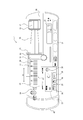
- FIG. 1 is a schematic view of a syringe pump 1 as a medical pump according to an embodiment of the present invention.
- FIG. 1 shows a syringe pump 1 with a syringe 50 attached.
- the syringe pump 1 is configured as a pump that sends a liquid contained in a hollow portion 52 of a syringe 50.
- the syringe pump 1 includes a mounting portion 11, a slider 12, a clamp 14, a cylinder flange retainer 15, an input button group 31, a first display unit 32, and a second display unit 33. And a housing 46.
- FIG. 1 is a schematic view of the front side of the syringe pump 1.
- the syringe pump 1 includes a grip portion 47 that can be gripped by an operator.
- the housing 46 of the syringe pump 1 of the present embodiment includes a handle as a grip portion 47 projecting from the left end portion in FIG. The operator can, for example, grip the grip portion 47 and carry the syringe pump 1.
- a syringe 50 can be attached to the syringe pump 1.
- the syringe 50 mounted on the mounting portion 11 is inserted into the hollow portion 52 from the base end side of the cylindrical cylinder 51 that partitions the hollow portion 52 inside, and the inner peripheral surface of the cylinder 51. It has a pusher 55 that can move the hollow portion 52 along the extending direction A of the cylinder 51 while closely adhering to the cylinder 51 in the circumferential direction.
- the cylinder 51 has a cylinder flange 53 at the base end portion, and an outlet hole 54 for communicating the hollow portion 52 and the outside is partitioned at the tip end portion.
- a flexible tube can be connected to the tip of the cylinder 51. When the tube is connected to the tip of the cylinder 51, the outlet hole 54 communicates with the flow path defined by the tube.
- a liquid such as a chemical solution is stored in the hollow portion 52 of the syringe 50.
- the mounting portion 11 can mount the cylinder 51 of the syringe 50. Further, as shown in FIG. 1, the cylinder flange retainer 15 accommodates a part of the cylinder flange 53 when the cylinder 51 of the syringe 50 is mounted on the mounting portion 11. As a result, the position of the cylinder 51 with respect to the syringe pump 1 is fixed.
- the slider 12 has a pusher fixing portion 13.
- the slider 12 is movable so as to engage with the pusher 55 of the syringe 50 mounted on the mounting portion 11. Specifically, the slider 12 can move along the extending direction A at a position on the proximal end side of the extending direction A with respect to the pusher 55 of the syringe 50 mounted on the mounting portion 11.
- the slider 12 fixes the pusher 55 of the syringe 50 mounted on the mounting portion 11 by the pusher fixing portion 13.
- the pusher 55 moves integrally with the slider 12 as the slider 12 moves along the extending direction A.
- the cylinder 51 mounted on the mounting portion 11 is fixed to the syringe pump 1 in the extending direction A by the cylinder flange retainer 15. Therefore, when the slider 12 moves to the tip end side of the syringe 50, the pusher 55 moves to the tip end side with respect to the cylinder 51, and the liquid contained in the hollow portion 52 is discharged from the outlet hole 54. In this way, the liquid contained in the hollow portion 52 can be sent into the living body through a flow path partitioned by a tube connectable to the tip end portion of the cylinder 51.
- the clamp 14 can be moved along the depth direction in the front view shown in FIG. 1, and can fix the cylinder 51 of the mounted syringe 50 so as to be sandwiched between the clamp 14 and the mounting portion 11. is there.
- a part of the cylinder flange 53 is hard to come off from the cylinder flange retainer 15, so that the cylinder 51 is firmly fixed to the syringe pump 1.
- the input button group 31 is arranged on the surface of the housing 46 and is composed of various operation buttons capable of accepting input operations by the operator.
- the input button group 31 includes, for example, a power button for switching on / off of the operating power of the syringe pump 1, a start button for starting liquid feeding, and a stop button for stopping liquid feeding.
- the input button group 31 outputs the input information to the control unit that executes various controls of the syringe pump 1.
- the first display unit 32 and the second display unit 33 include a display device such as a liquid crystal display or an organic EL display.
- the first display unit 32 and the second display unit 33 display various information based on the signal from the control unit.
- the first display unit 32 is configured by a touch screen capable of displaying information and detecting an input operation by an operator's finger.
- the touch screen constituting the first display unit 32 detects contact with the touch screen and identifies the contact position. For example, when the touch screen is a so-called capacitance method in which a change in capacitance when a finger or the like touches the touch screen is measured, contact is made based on the magnitude of capacitance or the amount of change thereof. Identify the location of the static electricity.
- the touch screen is a so-called resistance film method in which an electrode film comes into contact with a touch screen when a finger or the like presses the touch screen to allow electricity to flow and detect fluctuations in the voltage, it is based on the magnitude of the fluctuations in the voltage.
- the touch screen may be configured by other known methods.
- the touch screen is, for example, an ultrasonic surface acoustic wave method that detects a contact position by a finger or the like by attenuation of an ultrasonic surface acoustic wave, or an optical that detects a position where light emitted from a light source is blocked by a finger or the like. It may be configured by a method such as a method.
- the resolution of position detection on the touch screen may be determined as appropriate.
- the first display unit 32 outputs the information of the position where the finger or the like is in contact detected by the touch screen to the control unit that executes various controls of the syringe pump 1.
- the first display unit 32 is configured to be able to display, for example, an input button 36 that accepts an input operation by an operator's finger on a part of a display screen capable of displaying information. Further, the first display unit 32 is based on the control by the control unit provided in the syringe pump 1, for example, information set for liquid feed control by the syringe pump 1 on a part of the display screen (hereinafter, “liquid feed setting”). Information ”) 35 can be displayed.
- the liquid feed setting information 35 may include, for example, information currently set in the syringe pump 1, for example, information such as parameters.
- the syringe pump 1 When the touch screen of the first display unit 32 detects the contact position and the contact position is, for example, the position where the input button 36 is displayed, the syringe pump 1 performs an input operation on the input button 36. It is possible to detect that it has been damaged.
- the first display unit 32 may display information other than the above-mentioned information.
- the first display unit 32 may display various alarm information and the like.
- the second display unit 33 may display information on the actual amount of liquid to be sent by the syringe pump 1.
- the actual liquid feeding amount may include an actually measured value of the flow rate of the liquid being sent by the syringe pump 1, an actually measured value of the dose of the liquid being sent, and the like.
- the syringe pump 1 has been described as having two display units, a first display unit 32 and a second display unit 33, but the number of display units included in the syringe pump 1 is not two. You may.
- the syringe pump 1 may include only one display unit, and all the information displayed by the first display unit 32 and the second display unit 33 described above may be displayed on the one display unit.
- the syringe pump 1 is provided with three or more display units, and the information displayed by the first display unit 32 and the second display unit 33 described above may be distributed and displayed on the three or more display units. Good.
- FIG. 2 is a functional block diagram showing a schematic configuration of the syringe pump 1 shown in FIG.
- the syringe pump 1 has, as functional units, a communication unit 21, a storage unit 23, a control unit 24, an input button group 31, a first display unit 32, and a second display.
- a portion 33, a slider driving portion 37, a slider 12, and a pusher fixing portion 13 are provided. Since the functions of the input button group 31, the first display unit 32, the second display unit 33, the slider 12, and the pusher fixing unit 13 have been described above, description thereof will be omitted here.
- the communication unit 21 includes an interface for transmitting and receiving information to and from an information processing device such as an external computer by wireless communication or wired communication.
- the storage unit 23 is configured to include, for example, a storage device, and stores various information and programs. Specifically, the storage unit 23 stores a program for executing various processes executed by the control unit 24, various input support processes, and the like. Further, the storage unit 23 drives the slider drive unit 37 to send the liquid based on the information of the predetermined set values such as the flow rate and the dose of the liquid sent by the syringe pump 1 and the predetermined set values.
- the control unit 24 includes, for example, a processor that realizes a predetermined function by reading a predetermined information and program among various information and programs stored in the storage unit 23, and controls the operation of the entire syringe pump 1.
- the control unit 24 reads a predetermined information and program stored in the storage unit 23, and shifts the reception state for the input operation (hereinafter, simply referred to as "reception process"), based on the input operation. Therefore, it is possible to execute a process for executing the process related to the setting and the operation (hereinafter, simply referred to as “setting operation process”).
- the processing related to the setting and operation referred to here does not include the above reception processing. Details of the reception process and the setting operation process executed by the control unit 24 will be described later.
- the control unit 24 transmits / receives information to / from an external information processing device via the communication unit 21.
- the control unit 24 executes various processes based on the information input from the first display unit 32 composed of the input button group 31 and the touch screen, and the first display unit 32 executes the information associated with the execution of the various processes. And output from the second display unit 33.
- the slider drive unit 37 includes, for example, a motor, and moves the slider 12 along the extension direction A (see FIG. 1) based on a signal from the control unit 24.
- the control unit 24 can control the reception state for the input operation from the operator and execute the setting operation process based on the input operation from the operator. Specifically, the control unit 24 can control the reception state for the input operation on the touch screen from the operator, and can execute the setting operation process based on the input operation on the touch screen from the operator.
- the control unit 24 is configured to be able to execute setting operation processing based on an input operation according to the reception state.
- the setting operation process refers to the process related to the setting and operation as described above.
- the setting operation process includes a liquid transfer process related to liquid transfer.
- the liquid feeding process is a process relating to liquid feeding of the liquid contained in the hollow portion 52 of the syringe 50 mounted on the syringe pump 1.
- the liquid feeding process includes, for example, setting parameters in the setting items required for liquid feeding.
- the setting items required for liquid delivery include, but are not limited to, for example, "body weight", "drug amount” and "solution amount”.
- the setting item may be displayed in, for example, the liquid feed setting information 35.
- the control unit 24 When the control unit 24 detects, for example, an input operation for the input button 36, the control unit 24 executes the setting of the parameter of the setting item according to the input operation as the liquid feeding process.
- the liquid feed process may include, for example, the start and stop of the liquid feed.
- the liquid feed process may include the entire process relating to other liquid feeds.
- the setting operation process is not limited to the liquid transfer process.
- the setting operation processing includes all processing related to setting and operation.
- the setting operation process includes, for example, a process related to the touch screen itself, such as setting a display method and brightness, as a process related to the setting.
- the reception status is the status related to the reception of processing for the input operation from the operator.
- the reception state may be particularly related to the reception of processing for an input operation on the touch screen from the operator.
- the reception state is a state taken by the control unit 24, and the control unit 24 may execute different liquid feeding processes for the input operation depending on the reception state.
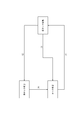
- FIG. 3 is a schematic view showing a mode of transition of the reception state in the syringe pump 1.
- the reception state has three states. Specifically, the reception state has three states: a locked state, a temporary locked state, and an unlocked state.
- the control unit 24 takes one of the three states as the reception state.
- the control unit 24 shifts the reception state based on the input operation on the touch screen according to the current reception state. The process of shifting the reception state in this way is the reception process.
- the locked state is a state in which the control unit 24 does not execute the liquid feeding process based on the input operation.
- the locked state may be a state in which the control unit 24 does not execute the liquid feeding process based on the input operation to the touch screen. That is, in the locked state, even if the operator executes an input operation on the touch screen, the control unit 24 does not execute the liquid feeding process based on the input operation.
- the input button 36 for accepting the input operation shown in FIG. 1 does not have to be displayed on the touch screen.
- the liquid feed setting information 35 may be displayed on the touch screen.
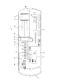
- the input button 36 in the locked state, is not displayed on the first display unit 32 configured by the touch screen, and only the liquid feed setting information 35 is displayed. It may be displayed.
- liquid feed setting information 35 even in the locked state, for example, information such as currently set parameters can be made visible to the operator or the like. Further, by not displaying the input button 36 in the locked state, the operator can recognize that the syringe pump 1 is in the locked state and the liquid feeding process by the input operation to the input button 36 is not executed.
- the temporary lock state is the state of the transition stage from the locked state to the unlocked state. That is, the temporary lock state is a reception state that is passed through when shifting from the locked state to the unlocked state.
- the control unit 24 detects the first input operation on the touch screen in the locked state, the control unit 24 executes a process of shifting to the temporary locked state as a reception process (see (1) in FIG. 3).
- the first input operation is, for example, a tap operation on the touch screen.
- the first input operation may be a tap operation at an arbitrary position on the touch screen.
- the tap operation means that the operator touches the touch screen with a finger or the like only once for a short time.
- the tap operation is an operation that does not involve movement of the contact position on the touch screen from the time the operator touches the finger or the like until the operator releases the finger or the like.
- the control unit 24 determines that the tap operation has been detected when the input operation is an operation that does not involve the movement of the contact position on the touch screen.
- not accompanied by movement of the contact position means that the finger in contact with the touch screen is within a range in which it is not recognized that the finger has moved due to the intention of the operator. That is, the control unit 24 determines that the tap operation has been input when the contact with the touch screen is detected within the range in which the finger touching the touch screen is not recognized as having moved due to the intention of the operator. To do.
- the range that is not recognized as having been moved due to the intention of the operator may be appropriately determined according to the specifications of the touch screen and the like.
- the control unit 24 may determine that the displacement of the contact position within the range is not accompanied by the movement of the contact position.
- the contact position detected on the touch screen may be displaced due to, for example, a change in pressing pressure by a finger in contact with the touch screen.
- the contact position detected by the touch screen is displaced, if the operator does not intend to move the finger in contact with the touch screen and intends to perform a tap operation, the contact is made.
- the displacement of the position is considered to be within the size of the pad of the finger.
- the control unit 24 determines that the displacement of the contact position within the range is not accompanied by the movement of the contact position, and determines that the tap operation has been input. Based on the same idea, the range that is not recognized as having moved due to the intention of the operator is defined as within a predetermined distance (for example, several mm to several cm) from the position where the touched finger is detected on the touch screen. May be done.
- a predetermined distance for example, several mm to several cm
- control unit 24 may determine that the touch position does not move only when the contact position of the tap operation with respect to the touch screen is one point. That is, in this case, only if contact continues to be detected at the position where contact was first detected on the touch screen until no contact is detected after the first contact is detected on the touch screen due to tapping. It is determined that it is a tap operation. In this case, the tap operation can be determined more strictly.
- the control unit 24 may determine that the tap operation has been detected when the time from detecting the contact with the touch screen to not detecting the contact is within a predetermined time.
- the tap operation means touching a finger or the like only once for a short time. Therefore, by setting a limit that the time from detecting the contact with the touch screen to not detecting the contact is within a predetermined time, that is, by setting a threshold value regarding the time, the tap operation is more accurate. Can be detected. For example, by setting a threshold value for time, it is possible to determine that an operation in a state where the touch screen is detected for a long time is not a tap operation even if the operation does not involve movement of the contact position.
- the predetermined time as a threshold value for time may be set to an appropriate length, for example, 1 second.
- both the input button 36 and the liquid feed setting information 35 are displayed on the touch screen, for example, as shown in FIG. In this way, when the locked state is released and the temporary locked state is entered, the input button 36 is displayed so that the operator can recognize that the locked state has been released.
- control unit 24 executes a process of shifting to either the unlocked state or the locked state according to the input operation from the operator. Specifically, when the control unit 24 detects a second input operation on the touch screen in the temporarily locked state, it executes a process of shifting to the unlocked state as a reception process (see (2) in FIG. 3). ..
- the second input operation is, for example, an input operation for the input button 36 displayed on the touch screen.
- the input operation in this case is a tap operation on the input button 36.
- the control unit 24 detects a tap operation at the position where the input button 36 is displayed on the touch screen, the control unit 24 executes a process of shifting the reception state from the temporary lock state to the unlocked state.
- the input button 36 accepts an input operation other than the tap operation, for example, when the input button 36 accepts an operation such as a slide operation in which the finger is moved while being in contact with the touch screen and then the finger is released, the second input operation is performed. Operations other than tap operation may be included. In the present embodiment, it will be described below assuming that the second input operation is a tap operation.
- the control unit 24 When the control unit 24 detects an input operation for the input button 36 as the second input operation, the control unit 24 executes a process of shifting the reception state from the temporary locked state to the unlocked state as described above, and inputs the input button 36 to the input button 36.
- the setting operation process according to the input operation may be executed. For example, as a second input operation, when an input operation for the input button 36 is detected, a process of shifting the reception state from the temporary locked state to the unlocked state is executed, and the input to the input button 36 is performed.
- the setting operation processing according to the operation the operator again presses the input button 36 to execute the setting operation processing such as the liquid feeding process after the reception state shifts from the temporary locked state to the unlocked state.
- the reception state can be changed without being aware of the distinction between the temporarily locked state and the unlocked state.
- the input operation other than the second input operation may be any input operation other than the second input operation among the input operations that can be detected by the control unit 24.
- an input operation other than the second input operation includes a touch operation to a position other than the input button 36 on the touch screen.
- the input operation other than the second input operation includes an operation other than the touch operation on the touch screen, for example, a slide operation and the like.
- an input operation other than the second input operation includes an input operation in which it is detected that input is performed at a plurality of points on the touch screen. For example, when two fingers are in contact with the touch screen, it is detected that input is performed at a plurality of points.
- the input operation other than the second input operation may be an input operation other than the touch screen. Specifically, for example, an input operation to a button of the input button group 31 corresponds to this.
- the control unit 24 may limit the input button 36 recognized as the second input operation to only a specific button. For example, among the plurality of input buttons 36 displayed on the touch screen, the input operation to some of the specified input buttons is recognized as the second input operation, and the input buttons other than the specified some input buttons are recognized.
- the input operation to the input button may be recognized as an input operation other than the second input operation.
- control unit 24 may execute a process of shifting to the locked state if the input operation is not detected for a predetermined time after shifting to the temporary locked state (see (3) in FIG. 3).
- the predetermined time may be set in advance in the syringe pump 1, or may be set by the operator at the start of use of the syringe pump 1.
- the predetermined time may be set, for example, in the range of several seconds to several minutes. If the predetermined time is too long, an erroneous operation based on an unintended input is likely to occur, and if it is too short, the operation becomes complicated and is not suitable for medical practice.
- the predetermined time is preferably set in the range of 5 seconds to 1 minute, and more preferably set in the range of 10 seconds to 20 seconds. With such a setting, it is possible to improve safety while suppressing complicated operations.
- the unlocked state is a state in which the control unit 24 executes the liquid feeding process based on the input operation. That is, in the unlocked state, the control unit 24 executes the liquid feeding process based on the input operation performed by the operator on the touch screen.
- control unit 24 may execute a process of shifting to the locked state as a reception process (see (4) in FIG. 3).
- control unit 24 executes the process of shifting the reception state between the locked state, the temporary locked state, and the unlocked state.
- reception state defines what kind of processing the control unit 24 executes in response to the input operation on the touch screen. It can be said that the reception state is a mode in which the control unit 24 determines the process to be executed for the input operation. Therefore, the control unit 24 executes the process corresponding to the input operation to the touch screen by the predetermined algorithm in each reception state.
- FIG. 5 is a flowchart showing an example of the migration process executed by the control unit 24 of FIG.
- the reception state is the locked state.
- the input button 36 is not displayed on the first display unit 32, and the liquid feed setting information 35 is displayed.
- the parameters currently set are displayed in the liquid feed setting information 35.
- the control unit 24 determines whether or not the first input operation on the touch screen has been detected (step S11). Specifically, in the present embodiment, the control unit 24 determines whether or not a tap operation has been performed with respect to an arbitrary position on the touch screen.
- step S11 When the control unit 24 determines that the first input operation on the touch screen has not been detected (No in step S11), the control unit 24 repeats step S11 until it determines that the first input operation on the touch screen has been detected. During this time, the reception state remains locked.
- control unit 24 determines that the first input operation for the touch screen has been detected (Yes in step S11)
- the control unit 24 executes a process of shifting the reception state from the locked state to the temporary locked state (step S12).
- the control unit 24 causes the first display unit 32 to display the input button 36, as shown as an example in FIG. From this display, the operator can recognize that the locked state has been released.
- the control unit 24 determines whether or not a second input operation to the touch screen has been detected (step S13). Specifically, in the present embodiment, the control unit 24 determines whether or not the input button 36 displayed on the touch screen has been tapped as an input operation.
- control unit 24 determines whether or not a predetermined time has elapsed without detecting the input operation on the touch screen. (Step S14).
- step S14 When the control unit 24 determines that the predetermined time has not yet elapsed in a state where the input operation on the touch screen is not detected (No in step S14), the control unit 24 proceeds to step S13. In this way, in the temporary lock state, the control unit 24 repeats steps S13 and S14 unless a second input operation is detected.
- step S14 when it is determined in step S14 that the predetermined time has elapsed in a state where the input operation to the touch screen is not detected (Yes in step S14), the control unit 24 executes a process of shifting the reception state to the locked state. (Step S17). At this time, the control unit 24 erases the display of the input button 36 displayed on the first display unit 32, as shown as an example in FIG. That is, the control unit 24 hides the input button 36. As a result, the operator can recognize that the locked state has been set. In this case, the control unit 24 shifts to step S11. At this time, the display of the input button 36 may not be completely erased, and the display may be darkened.
- step S13 When it is determined in step S13 that the second input operation to the touch screen is detected in the temporary lock state (Yes in step S13), the control unit 24 executes a process of shifting the reception state to the unlocked state (Yes). Step S15).
- the second input operation is an input operation for the input button 36 displayed on the touch screen as described above, and the control unit 24 determines that the second input operation for the touch screen has been detected.
- the setting operation process corresponding to the input operation to the input button 36 is executed.
- control unit 24 After shifting the reception state to the unlocked state in step S15, the control unit 24 executes setting operation processing such as liquid feeding processing based on an input operation by the operator. For example, the control unit 24 sets (changes) the value of the parameter in the setting item based on the input operation by the operator.
- the control unit 24 determines whether or not a predetermined time has elapsed in the unlocked state without detecting the input operation on the touch screen (step S16).
- control unit 24 determines that the predetermined time has not yet elapsed in the state where the input operation to the touch screen is not detected (No in step S16)
- the control unit 24 continues the process in the unlocked state.
- the control unit 24 repeats step S16 until it is determined that a predetermined time has elapsed without detecting an input operation on the touch screen. Therefore, as long as the input operation on the touch screen is not detected and the predetermined time does not elapse, that is, as long as the operator performs the input operation on the touch screen before the predetermined time elapses, the unlocked state continues. To.
- the control unit 24 executes a process of shifting the reception state to the locked state when it is determined that a predetermined time has elapsed (Yes in step S16) in a state where no input operation to the touch screen is detected (Yes). Step S17). At this time, as described above, the control unit 24 erases the display of the input button 36 displayed on the first display unit 32. In this case, the control unit 24 shifts to step S11.
- the syringe pump 1 is in the reception state by the control unit 24 between the locked state, the unlocked state, and the temporary locked state which is the transition stage from the locked state to the unlocked state. Execute the migration process of. For example, when the control unit 24 does not have a temporary lock state as a reception state and shifts the reception state only between the locked state and the unlocked state, the touch screen comes into contact due to liquid adhesion, cleaning, or the like. If detected, there is a high possibility that the operator will shift to an unlocked state in which the liquid feeding process based on the input operation is executed even if the operator does not intend.
- the temporary lock state which is the transition stage from the locked state to the unlocked state as in the present embodiment
- the state of the temporary locked state is passed before the transition from the locked state to the unlocked state. Therefore, the possibility that the operator unintentionally enters the unlocked state is reduced. Therefore, the possibility that an unintended input operation to the syringe pump 1 is accepted is reduced, and as a result, safety can be improved.
- the control unit 24 when the control unit 24 detects the first input operation to the touch screen, it executes a process of shifting to the temporary lock state.
- the first input operation is a tap operation as in the present embodiment
- the tap operation is a simple operation of touching the touch screen with a finger or the like only once for a short time, so that the operator can easily lock the state. Can be released. That is, the operator can easily release the locked state, for example, when he / she wants to perform an input operation for causing the syringe pump 1 to execute the liquid feeding process. Therefore, the convenience for the operator is improved.
- the control unit 24 executes a process of shifting to the unlocked state when the second input operation is detected in the temporarily locked state.
- the control unit 24 detects an input operation other than the second input operation in the temporary lock state
- the control unit 24 executes a process of shifting to the lock state. Therefore, for example, even if the operator unintentionally shifts from the locked state to the temporary locked state, unless the second input operation is detected, the setting operation process based on the input operation is executed in the unlocked state. Do not migrate. Therefore, the possibility that the operator is unintentionally unlocked is further reduced, and the safety is further improved.
- the second input operation is an input operation for the input button 36 as in the syringe pump 1 according to the present embodiment
- the input button 36 is performed as a natural operation by the operator in order to execute the setting operation process.
- the temporary locked state is changed to the unlocked state. Therefore, for the operator, when the intended transition to the unlocked state is performed, the transition to the unlocked state can be performed by a natural operation.
- the setting operation processing is executed when the operator is performing the input operation intended by executing the setting operation processing according to the input operation. The operator is not made to execute the input operation for the input button 36 again in order to make the input button 36.
- the setting operation process can be executed according to the intention of the operator, and the operator is made aware of the distinction between the temporarily locked state and the unlocked state. It is possible to shift the reception status without.
- control unit 24 executes a process of shifting to the locked state when the input operation is not detected for a predetermined time in the temporarily locked state or the unlocked state. As a result, it becomes easy to prevent a malfunction based on an unintended input by shifting to the locked state when the operator is not trying to perform an input operation. Therefore, the safety is further improved.
- the input button 36 as the first input unit is displayed on the first display unit 32, but the input button 36 does not necessarily have to be displayed on the first display unit 32.
- the syringe pump 1 may separately include an input unit provided apart from the first display unit 32.
- the input unit has the same function as the input button 36. In this case, the operator can perform an input operation on the input unit.
- the medical pump is described as the syringe pump 1, but the medical pump is not limited to this.
- other medical pumps include infusion pumps, nutrition pumps, insulin pumps, blood pumps and the like.
- the present disclosure relates to a medical pump and an information processing method, and particularly to a medical pump that accepts an input operation by an operator and an information processing method thereof.
Landscapes
- Engineering & Computer Science (AREA)
- Health & Medical Sciences (AREA)
- Theoretical Computer Science (AREA)
- General Engineering & Computer Science (AREA)
- Public Health (AREA)
- Veterinary Medicine (AREA)
- Hematology (AREA)
- Life Sciences & Earth Sciences (AREA)
- Animal Behavior & Ethology (AREA)
- General Health & Medical Sciences (AREA)
- Biomedical Technology (AREA)
- Heart & Thoracic Surgery (AREA)
- Anesthesiology (AREA)
- Human Computer Interaction (AREA)
- Physics & Mathematics (AREA)
- General Physics & Mathematics (AREA)
- Vascular Medicine (AREA)
- Infusion, Injection, And Reservoir Apparatuses (AREA)
- External Artificial Organs (AREA)
- User Interface Of Digital Computer (AREA)
Abstract
医療用ポンプは、情報を表示可能であるとともに、操作者による入力操作を検出可能なタッチスクリーンと、前記操作者による入力操作に対する受付状態を制御するとともに、前記操作者による入力操作に基づいて、設定及び動作に係る設定動作処理を実行可能な、制御部と、を備え、前記制御部は、前記受付状態について、前記入力操作に基づく前記設定動作処理を実行しないロック状態と、前記入力操作に基づく前記設定動作処理を実行する非ロック状態と、前記ロック状態から前記非ロック状態への移行段階である仮ロック状態との間で、受付状態の移行処理を実行する。
Description
本開示は、医療用ポンプ及び情報処理方法に関し、特に操作者による入力操作を受け付ける医療用ポンプ及びその情報処理方法に関する。
操作者による入力操作を受け付ける入力デバイスを備え、受け付けた入力操作に基づいて設定値の設定を行い、設定された設定値に基づいて動作する医療用ポンプが知られている。このような医療用ポンプとして、例えば、薬液等の液体が収容されたシリンジが載置され、載置されたシリンジの押子を押し出す速度を、操作者により設定された設定値に従って制御することで、流量を制御しながら患者等の生体内に液体を送液するシリンジポンプが挙げられる。シリンジポンプ等の医療用ポンプは、例えば投与速度等の所定の設定値の設定に用いられる、タッチパネル等の入力デバイスを有する(例えば、特許文献1参照)。
特許文献1に開示されたシリンジポンプは、タッチ操作を受け付けるタッチパネルを有し、ユーザによるタッチパネルへのタッチ操作を受け付けることができる。このタッチパネルは、操作者によるタッチ操作の場合だけでなく、例えば、液体がタッチパネルに付着した場合や、タッチパネルの清掃のために表面を拭ったりした場合にも、反応することがある。しかしながら、このような液体の付着や清掃に基づく反応は、操作者が意図して操作したものではないため、液体の付着や清掃に基づく反応により動作が実行された場合、誤動作となる。しかも、医療現場では、輸液バッグを取り扱う等、液体を使用する機会が多く、このように液体を取り扱う際にタッチパネルに液体が付着したり、付着した液体を除去するために清掃を行ったりする機会が多い。また、医療用ポンプの用途の性質上、誤動作が発生すると、例えば薬液を投与される患者に、生命の危機の影響が及ぶ可能性がある。
本開示の目的は、安全性を向上できる医療用ポンプ及び情報処理方法を提供することである。
本発明の第1の態様としての医療用ポンプは、情報を表示可能であるとともに、操作者による入力操作を検出可能なタッチスクリーンと、前記操作者による入力操作に対する受付状態を制御するとともに、前記操作者による入力操作に基づいて、設定及び動作に係る設定動作処理を実行可能な、制御部と、を備え、前記制御部は、前記受付状態について、前記入力操作に基づく前記設定動作処理を実行しないロック状態と、前記入力操作に基づく前記設定動作処理を実行する非ロック状態と、前記ロック状態から前記非ロック状態への移行段階である仮ロック状態との間で、受付状態の移行処理を実行する。
本発明の一実施形態としての医療用ポンプにおいて、前記設定動作処理は、送液に関する送液処理を含む。
本発明の一実施形態としての医療用ポンプにおいて、前記制御部は、前記ロック状態において、前記タッチスクリーンに対する第1の入力操作を検出すると、前記仮ロック状態に移行する処理を実行する。
本発明の一実施形態としての医療用ポンプにおいて、前記第1の入力操作は、前記タッチスクリーンに対するタップ操作である。
本発明の一実施形態としての医療用ポンプにおいて、前記制御部は、前記仮ロック状態において、前記タッチスクリーンに対する第2の入力操作を検出すると、前記非ロック状態に移行する処理を実行する。
本発明の一実施形態としての医療用ポンプにおいて、前記第2の入力操作は、前記タッチスクリーンに表示された入力ボタンに対する入力操作である。
本発明の一実施形態としての医療用ポンプにおいて、前記制御部は、前記第2の入力操作として前記入力ボタンに対する入力操作を検出すると、前記入力ボタンへの入力操作に応じた設定動作処理を実行する。
本発明の一実施形態としての医療用ポンプにおいて、前記制御部は、前記仮ロック状態において、前記第2の入力操作でない入力操作を検出すると、前記ロック状態に移行する処理を実行する。
本発明の一実施形態としての医療用ポンプにおいて、前記制御部は、前記仮ロック状態又は前記非ロック状態において、前記タッチスクリーンに対する入力操作を所定時間検出していないと判定した場合、前記ロック状態に移行する処理を実行する。
本発明の一実施形態としての医療用ポンプにおいて、前記医療用ポンプは、シリンジポンプ、輸液ポンプ、栄養ポンプ、インスリンポンプ又は血液ポンプである。
本発明の第2の態様としての情報処理方法は、情報を表示可能であるとともに、操作者による入力操作を検出可能なタッチスクリーンを備え、前記操作者による入力操作に対する受付状態を制御するとともに、前記操作者による入力操作に基づいて、設定及び動作に係る設定動作処理を実行可能な医療用ポンプにより実行される情報処理方法であって、前記受付状態について、前記入力操作に基づく前記設定動作処理を実行しないロック状態と、前記入力操作に基づく前記設定動作処理を実行する非ロック状態と、前記ロック状態から前記非ロック状態への移行段階である仮ロック状態との間で、受付状態の移行処理を実行するステップを含む。
本開示の医療用ポンプ及び情報処理方法によると、安全性を向上できる。
以下、本発明の一実施形態について、図面を参照して説明する。各図において共通の構成部には、同一の符号を付している。
図1は、本発明の一実施形態の医療用ポンプとしてのシリンジポンプ1の概略図である。図1は、シリンジ50を装着した状態のシリンジポンプ1を示す。図1に示すように、シリンジポンプ1は、シリンジ50の中空部52に収容された液体を送液するポンプとして構成されている。
図1に示すように、シリンジポンプ1は、載置部11と、スライダ12と、クランプ14と、シリンダフランジ押さえ15と、入力ボタン群31と、第1表示部32と、第2表示部33と、ハウジング46と、を備える。
本明細書において、以下、シリンジポンプ1の、第1表示部32が配置されている側を、正面側という。従って、図1は、シリンジポンプ1の正面側の概略図である。図1に示すように、シリンジポンプ1は、操作者が把持することが可能な把持部47を備える。より具体的には、本実施形態のシリンジポンプ1のハウジング46は、図1における左側の端部から突設されている把持部47としての取っ手を備える。操作者は、例えば、把持部47を把持して、シリンジポンプ1を持ち運ぶことができる。
図1に示すように、シリンジポンプ1には、シリンジ50を装着可能である。載置部11に載置されるシリンジ50は、内部に中空部52を区画する円筒状のシリンダ51と、シリンダ51の基端側から中空部52内に挿入され、シリンダ51の内周面の周方向に隙間なく密着しながらシリンダ51の延在方向Aに沿って中空部52を移動可能な押子55と、を有する。シリンダ51は、基端部にシリンダフランジ53を有し、先端部に中空部52と外部とを連通する出口孔54を区画している。シリンダ51の先端部には、可撓性を有するチューブが接続可能である。シリンダ51の先端部にチューブが接続されると、出口孔54がチューブにより区画された流路と連通する。シリンジ50の中空部52には、薬液等の液体が収容される。
図1に示すように、載置部11は、シリンジ50のシリンダ51を載置可能である。また、図1に示すように、シリンダフランジ押さえ15は、載置部11にシリンジ50のシリンダ51が載置されると、シリンダフランジ53の一部を収納する。これにより、シリンダ51のシリンジポンプ1に対する位置が、固定される。
図1に示すように、スライダ12は、押子固定部13を有する。スライダ12は、載置部11に載置されるシリンジ50の押子55と係合するように移動可能である。具体的には、スライダ12は、載置部11に載置されるシリンジ50の押子55よりも延在方向Aの基端側の位置で、延在方向Aに沿って移動可能である。スライダ12は、押子固定部13により、載置部11に載置されたシリンジ50の押子55を固定する。押子55は、押子固定部13によりスライダ12に固定された状態では、スライダ12の延在方向Aに沿う移動に伴ってスライダ12と一体的に移動する。このとき、載置部11に載置されたシリンダ51は、シリンダフランジ押さえ15によって、シリンジポンプ1に対して延在方向Aにおいて固定されている。従って、スライダ12がシリンジ50の先端側に移動すると、押子55がシリンダ51に対して先端側に移動し、中空部52に収容された液体が出口孔54から排出される。このようにして、中空部52に収容された液体を、シリンダ51の先端部に接続可能なチューブにより区画された流路を通じて生体内に向かって送液することができる。
クランプ14は、図1に示す正面視において、奥行き方向に沿って移動可能であり、載置されたシリンジ50のシリンダ51を載置部11との間で挟み込むようにして固定することが可能である。クランプ14でシリンダ51を固定することで、シリンダフランジ53の一部がシリンダフランジ押さえ15から外れにくくなるため、シリンダ51はシリンジポンプ1に対して強固に固定される。
図1に示すように、入力ボタン群31は、ハウジング46の表面に配置され、操作者による入力操作を受け付け可能な各種の操作ボタンで構成される。入力ボタン群31は、例えば、シリンジポンプ1の動作電源のオンオフを切り替えるための電源ボタン、送液を開始するための開始ボタン、送液を停止するための停止ボタンを含む。入力ボタン群31は、入力された情報を、シリンジポンプ1の各種制御を実行する制御部に出力する。
第1表示部32及び第2表示部33は、例えば液晶ディスプレイ又は有機ELディスプレイなどの表示デバイスを含む。第1表示部32及び第2表示部33は、上記制御部からの信号に基づいて、各種情報を表示する。
本実施形態において、第1表示部32は、情報を表示可能であるとともに、操作者の指による入力操作を検出可能なタッチスクリーンにより構成されている。第1表示部32を構成するタッチスクリーンは、タッチスクリーンに対する接触を検出し、接触した位置を特定する。例えば、タッチスクリーンが、指等がタッチスクリーンに触れた際の静電容量の変化を測定する、いわゆる静電容量方式である場合、静電容量の大きさ又はその変化量等に基づいて、接触した位置を特定する。例えば、タッチスクリーンが、指等がタッチスクリーンを押圧することで電極膜が接触して電気が流れ、その電圧の変動を検出する、いわゆる抵抗膜方式である場合、電圧の変動の大きさに基づいて、接触した位置を特定する。タッチスクリーンは、その他の公知の方式により構成されていてよい。タッチスクリーンは、例えば、指等による接触位置を超音波表面弾性波の減衰によって検出する、超音波表面弾性波方式や、光源から射出される光が指等により遮光された位置を検出する、光学方式等の方式により構成されていてよい。タッチスクリーンにおける位置の検出の分解能は、適宜定められてよい。第1表示部32は、タッチスクリーンにより検出した、指等が接触している位置の情報を、シリンジポンプ1の各種制御を実行する制御部に出力する。
第1表示部32は、例えば、情報を表示可能な表示画面の一部に、操作者の指による入力操作を受け付ける入力ボタン36を表示可能に構成されている。また、第1表示部32は、シリンジポンプ1が備える制御部による制御に基づき、例えば、表示画面の一部に、シリンジポンプ1による送液制御のために設定される情報(以下「送液設定情報」という)35を表示可能に構成されている。送液設定情報35は、例えば、シリンジポンプ1において現在設定されている情報、例えばパラメータ等の情報を含んでよい。第1表示部32のタッチスクリーンが接触の位置を検出し、当該接触の位置が、例えば入力ボタン36が表示された位置である場合、シリンジポンプ1は、入力ボタン36に対して入力操作が行われたことを検出することができる。
なお、第1表示部32は、上述した情報以外の情報を表示してよい。例えば、第1表示部32は、各種の警報情報等を表示してもよい。
第2表示部33は、シリンジポンプ1による実際の送液量の情報を表示してよい。実際の送液量は、シリンジポンプ1が送液している液体の流量の実測値又は送液されている液体の投与量の実測値等を含んでよい。
なお、本実施形態では、シリンジポンプ1が第1表示部32と第2表示部33との2つの表示部を備えるとして説明したが、シリンジポンプ1が備える表示部の数量は、2つでなくてもよい。例えば、シリンジポンプ1は、表示部を1つのみ備え、上述した第1表示部32及び第2表示部33により表示される全ての情報を、当該1つの表示部に表示してもよい。また、シリンジポンプ1は、3つ以上の表示部を備え、上述した第1表示部32及び第2表示部33により表示される情報を、3つ以上の表示部に分散して表示させてもよい。
図2は、図1に示すシリンジポンプ1の概略構成を示す機能ブロック図である。図2では、シリンジポンプ1により実行される処理に関連する機能部のみを図示しており、例えば、ハウジング46等の処理に関連しない構成については、図示していない。図2に示されているように、シリンジポンプ1は、機能部として、通信部21と、記憶部23と、制御部24と、入力ボタン群31と、第1表示部32と、第2表示部33と、スライダ駆動部37と、スライダ12と、押子固定部13とを備える。入力ボタン群31、第1表示部32、第2表示部33、スライダ12、及び押子固定部13の機能については、上述したため、ここでは説明を省略する。
通信部21は、無線通信又は有線通信により、外部のコンピュータ等の情報処理装置との間で情報の送受信を行うインターフェースを含む。
記憶部23は、例えば記憶装置を含んで構成され、種々の情報及びプログラムを記憶する。具体的には、記憶部23は、制御部24が実行する各種処理、各種の入力支援処理等を実行するためのプログラムを記憶する。また、記憶部23は、シリンジポンプ1により送液される液体の流量及び投与量等の所定の設定値の情報、及び所定の設定値に基づいてスライダ駆動部37を駆動させて送液するための制御プログラム等を記憶する。
制御部24は、例えば記憶部23に記憶された種々の情報及びプログラムのうち、所定の情報及びプログラムを読み込むことにより所定の機能を実現するプロセッサを含み、シリンジポンプ1全体の動作を制御する。本実施形態において、制御部24は、記憶部23に記憶された所定の情報及びプログラムを読み込み、入力操作に対する受付状態を移行させる処理(以下、単に「受付処理」という)と、入力操作に基づいて、設定及び動作に係る処理を実行する処理(以下、単に「設定動作処理」という)とを実行可能である。なお、ここでいう設定及び動作に係る処理には、上記受付処理は含まれない。制御部24により実行される受付処理及び設定動作処理の詳細については、後述する。
制御部24は、通信部21を介して、外部の情報処理装置との間で情報の送受信を行う。制御部24は、入力ボタン群31及びタッチスクリーンにより構成される第1表示部32から入力された情報に基づいて各種の処理を実行し、各種の処理の実行に伴う情報を第1表示部32及び第2表示部33から出力する。
スライダ駆動部37は、例えばモータを含み、制御部24からの信号に基づいて、スライダ12を延在方向A(図1参照)に沿って移動させる。
次に、本実施形態における制御部24が実行する処理の詳細について説明する。制御部24は、操作者からの入力操作に対する受付状態を制御するとともに、操作者からの入力操作に基づいて、設定動作処理を実行可能である。具体的には、制御部24は、操作者からのタッチスクリーンに対する入力操作に対する受付状態を制御するとともに、操作者からのタッチスクリーンに対する入力操作に基づいて、設定動作処理を実行可能である。制御部24は、受付状態に応じて、入力操作に基づく設定動作処理を実行可能に構成されている。
設定動作処理は、上述のように設定及び動作に係る処理を言う。設定動作処理は、具体的な一例として、送液に関する送液処理を含む。送液処理は、シリンジポンプ1に装着されたシリンジ50の中空部52に収容された液体の送液に関する処理である。送液処理は、例えば、送液のために要求される設定項目におけるパラメータの設定を含む。送液のために要求される設定項目は、例えば、「体重」、「薬剤量」及び「溶液量」を含むが、これらに限られるものではない。設定項目は、例えば送液設定情報35に表示されてよい。制御部24は、例えば、入力ボタン36に対する入力操作を検出すると、送液処理として、入力操作に応じて設定項目のパラメータの設定を実行する。送液処理は、例えば、送液の開始及び停止を含んでよい。送液処理は、その他の送液に関する処理の全体を含んでよい。
設定動作処理は、送液処理に限られない。設定動作処理は、設定及び動作に係る処理全般を含む。設定動作処理は、設定に係る処理として、例えば、タッチスクリーンそのものに関する、表示方式や輝度の設定等の処理を含む。
受付状態は、操作者からの入力操作に対する処理の受付に関する状態である。受付状態は、特に、操作者からのタッチスクリーンへの入力操作に対する処理の受付に関する状態であってよい。受付状態は、制御部24が取る状態であり、制御部24は、受付状態に応じて、入力操作に対して、異なる送液処理を実行し得る。
ここで、受付状態について、図3を参照しながら説明する。図3は、シリンジポンプ1における受付状態の移行の態様を示す概略図である。図3に示すように、本実施形態において、受付状態は、3つの状態を有する。具体的には、受付状態は、ロック状態と、仮ロック状態と、非ロック状態との、3つの状態を有する。制御部24は、受付状態としての3つの状態のいずれかを取る。制御部24は、現在の受付状態に応じて、タッチスクリーンへの入力操作に基づき、受付状態を移行させる。このように受付状態を移行させる処理が、受付処理である。
ロック状態は、制御部24が、入力操作に基づく送液処理を実行しない状態である。ロック状態は、特に、制御部24が、タッチスクリーンへの入力操作に基づく送液処理を実行しない状態であってよい。すなわち、ロック状態である場合、操作者がタッチスクリーンに対して入力操作を実行した場合であっても、制御部24は、当該入力操作に基づいた送液処理を実行しない。
ロック状態において、タッチスクリーンには、図1に示した入力操作を受け付ける入力ボタン36が表示されなくてよい。ロック状態において、タッチスクリーンには、送液設定情報35が表示されていてよい。本実施形態では、図4に一例として示されているように、ロック状態において、タッチスクリーンにより構成される第1表示部32には、入力ボタン36が表示されず、送液設定情報35のみが表示されてよい。このように、ロック状態において入力ボタン36を表示させないことにより、入力操作に基づく送液処理を実行しないロック状態である場合における、シリンジポンプ1のエネルギー消費を抑制できる。一方で、ロック状態であっても送液設定情報35を表示させることにより、例えば現在設定されているパラメータ等の情報を、操作者等に視認可能な状態とすることができる。また、ロック状態において入力ボタン36を表示させないことにより、操作者は、シリンジポンプ1がロック状態であり、入力ボタン36に対する入力操作による送液処理が実行されないことを認識することができる。
仮ロック状態は、ロック状態から非ロック状態への移行段階の状態である。すなわち、仮ロック状態は、ロック状態から非ロック状態に移行する場合に、経由される受付状態である。制御部24は、ロック状態において、タッチスクリーンに対する第1の入力操作を検出すると、受付処理として、仮ロック状態に移行する処理を実行する(図3の(1)参照)。
第1の入力操作は、例えば、タッチスクリーンに対するタップ操作である。第1の入力操作は、タッチスクリーンの任意の位置におけるタップ操作であってよい。タップ操作は、操作者が、タッチスクリーンに、指等を一度だけ短時間接触させることをいう。タップ操作は、操作者が指等を接触させてから離すまで、タッチスクリーンにおける接触位置の移動を伴わない操作をいう。制御部24は、入力操作が、タッチスクリーンにおける接触位置の移動を伴わない操作である場合に、タップ操作が検出されたと判定する。
ここで、接触位置の移動を伴わないとは、タッチスクリーンに接触した指が、操作者の意図により移動したものと認められない範囲内であることをいう。すなわち、制御部24は、タッチスクリーンに接触した指が、操作者の意図により移動したものと認められない範囲内において、タッチスクリーンへの接触が検出される場合に、タップ操作が入力されたと判定する。操作者の意図により移動したものと認められない範囲は、タッチスクリーンの仕様等に応じて適宜定められてよい。
例えば、タッチスクリーンにおいて、接触した指を検出した位置から、平均的な人の指の腹の大きさの範囲内で接触位置が変位したとする。この場合、制御部24は、当該範囲内での接触位置の変位を、接触位置の移動を伴わないものであると判定してよい。人がタッチスクリーンにタップ操作を入力しようとする場合、例えばタッチスクリーンに接触する指による押圧力の変化等により、タッチスクリーンで検出される接触位置が変位することがある。しかしながら、たとえタッチスクリーンで検出される接触位置が変位したとしても、操作者が、指をタッチスクリーンに接触させた状態で移動させようとしたものではなく、タップ操作を意図している場合、接触位置の変位は、指の腹の大きさの範囲内に収まると考えられる。そこで、制御部24は、当該範囲内での接触位置の変位を、接触位置の移動を伴わないものであると判定し、タップ操作が入力されたと判定する。これと同様の思想に基づき、操作者の意図により移動したものと認められない範囲は、タッチスクリーンにおいて接触した指を検出した位置から所定の距離(例えば数mmから数cm)の範囲内と定められてもよい。
なお、制御部24は、タッチスクリーンに対するタップ操作の接触位置が、1点である場合のみを、接触位置の移動を伴わないと判定してもよい。つまり、この場合、タップ操作のためにタッチスクリーンに最初に接触が検出された後、接触が検出されなくなるまで、タッチスクリーンに最初に接触が検出された位置において接触が検出され続ける場合にのみ、タップ操作であると判定される。この場合、より厳密にタップ操作を判定することができる。
制御部24は、タッチスクリーンへの接触を検出してから接触を検出しなくなるまでの時間が所定時間内である場合に、タップ操作が検出されたと判定してもよい。タップ操作は、上述のように、指等を一度だけ短時間接触させることをいう。そのため、このようにタッチスクリーンへの接触を検出してから接触を検出しなくなるまでの時間が所定時間内であるという制限を設けることにより、すなわち時間に関する閾値を設けることにより、より正確にタップ操作を検出し得る。例えば、時間に関する閾値を設けることにより、接触位置の移動を伴わない操作であっても、長時間タッチスクリーンが検出した状態の操作を、タップ操作ではない操作と判定することができる。時間に関する閾値としての上記所定時間は、例えば1秒等、適宜の長さが設定されてよい。
仮ロック状態において、タッチスクリーンには、例えば図1に示すように、入力ボタン36と送液設定情報35との双方が表示される。このように、ロック状態が解除されて仮ロック状態に移行した場合に、入力ボタン36が表示されることにより、操作者は、ロック状態が解除されたことを認識することができる。
制御部24は、仮ロック状態である場合、操作者からの入力操作に応じて、非ロック状態又はロック状態のいずれかに移行する処理を実行する。具体的には、制御部24は、仮ロック状態において、タッチスクリーンに対する第2の入力操作を検出すると、受付処理として、非ロック状態に移行する処理を実行する(図3の(2)参照)。
第2の入力操作は、例えば、タッチスクリーンに表示された入力ボタン36に対する入力操作である。この場合の入力操作は、入力ボタン36に対するタップ操作である。この場合、制御部24は、タッチスクリーンにおいて、入力ボタン36が表示された位置におけるタップ操作を検出した場合に、受付状態を仮ロック状態から非ロック状態に移行する処理を実行する。なお、入力ボタン36が、タップ操作以外の入力操作を受け付ける場合、例えば指をタッチスクリーンに接触させたまま移動させてから指を離すスライド操作等の操作を受け付ける場合、第2の入力操作は、タップ操作以外の操作を含んでよい。本実施形態では、第2の入力操作がタップ操作であるとして、以下説明する。
制御部24は、第2の入力操作として、入力ボタン36に対する入力操作を検出すると、上述したように受付状態を仮ロック状態から非ロック状態に移行する処理を実行するとともに、入力ボタン36への入力操作に応じた設定動作処理を実行してよい。例えば、このように、第2の入力操作として、入力ボタン36に対する入力操作を検出したときに、受付状態を仮ロック状態から非ロック状態に移行する処理を実行するとともに、入力ボタン36への入力操作に応じた設定動作処理を実行することにより、操作者は、受付状態が仮ロック状態から非ロック状態に移行した後に、送液処理等の設定動作処理を実行させるために再度入力ボタン36に対する入力操作を行う必要がない。つまり、操作者に対して、入力操作に基づいて送液処理を実行させる場合、仮ロック状態と非ロック状態との区別を意識させることなく、受付状態を移行させることができる。
制御部24は、仮ロック状態において、タッチスクリーンに対する、第2の入力操作でない入力操作を検出すると、受付処理として、ロック状態に移行する処理を実行する(図3の(3)参照)。第2の入力操作でない入力操作は、制御部24が検出できる入力操作のうち、第2の入力操作を除く全ての入力操作であってよい。例えば、第2の入力操作でない入力操作は、タッチスクリーンにおける入力ボタン36以外の位置へのタッチ操作を含む。また、例えば、第2の入力操作でない入力操作は、タッチスクリーンに対するタッチ操作以外の操作、例えばスライド操作等を含む。また、例えば、第2の入力操作でない入力操作は、タッチスクリーン上において、複数点に入力がされていると検出される入力操作を含む。例えば、2本の指がタッチスクリーンに接触している場合、複数点に入力がされていると検出される。また、例えば、第2の入力操作でない入力操作は、タッチスクリーン以外への入力操作であってよい。具体的には、例えば、入力ボタン群31のボタンへの入力操作等が、これに該当する。
制御部24は、第2の入力操作として認識する入力ボタン36を、特定のボタンのみに限定してもよい。例えば、タッチスクリーンに表示されている複数の入力ボタン36のうち、特定された一部の入力ボタンへの入力操作を、第2の入力操作として認識し、特定された一部の入力ボタン以外の入力ボタンへの入力操作を、第2の入力操作でない入力操作として認識してもよい。
なお、制御部24は、仮ロック状態に移行してから、入力操作を所定時間検出しない場合、ロック状態に移行する処理を実行してよい(図3の(3)参照)。所定時間は、予めシリンジポンプ1において設定されていてもよく、操作者によって、シリンジポンプ1の使用開始時に設定されてもよい。所定時間は、例えば、数秒から数分の範囲で設定されてよい。所定時間は、長過ぎる場合は意図しない入力に基づく誤操作を引き起こしやすく、短過ぎる場合は操作が煩雑となるため医療現場には適さない。従って、シリンジポンプ1のような医療用ポンプにおいて、所定時間は、5秒間から1分間の範囲で設定されることが好ましく、そのうち、10秒間から20秒間の範囲で設定されることがより好ましい。このような設定により、煩雑な操作を抑えつつ安全性を向上させることができる。
非ロック状態は、制御部24が、入力操作に基づく送液処理を実行する状態である。すなわち、非ロック状態である場合、制御部24は、操作者がタッチスクリーンに対して行った入力操作に基づいて、送液処理を実行する。
制御部24は、非ロック状態において、入力操作を所定時間検出しない場合、受付処理として、ロック状態に移行する処理を実行してよい(図3の(4)参照)。
このようにして、制御部24は、ロック状態と、仮ロック状態と、非ロック状態との間で、受付状態の移行処理を実行する。
なお、受付状態は、タッチスクリーンへの入力操作に対して、制御部24がどのような処理を実行するかを規定するものである。受付状態は、制御部24が入力操作に対して実行する処理を定めるモードであると言うことができる。従って、制御部24は、各受付状態において、それぞれ予め定められたアルゴリズムで、タッチスクリーンへの入力操作に応じた処理を実行する。
図5は、図2の制御部24が実行する移行処理の一例を示すフローチャートである。図5のフローの開始時点において、受付状態はロック状態である。このとき、第1表示部32には、図4に一例として示すように、入力ボタン36が表示されず、送液設定情報35が表示されている。送液設定情報35には、例えば、現在設定されているパラメータが表示されている。
制御部24は、タッチスクリーンに対する第1の入力操作を検出したか否かを判定する(ステップS11)。本実施形態では、具体的には、制御部24は、タッチスクリーンの任意の位置に対して、タップ操作がされたか否かを判定する。
制御部24は、タッチスクリーンに対する第1の入力操作を検出していないと判定した場合(ステップS11のNo)、タッチスクリーンに対する第1の入力操作を検出したと判定するまで、ステップS11を繰り返す。この間、受付状態は、ロック状態のままである。
制御部24は、タッチスクリーンに対する第1の入力操作を検出したと判定した場合(ステップS11のYes)、受付状態をロック状態から仮ロック状態に移行する処理を実行する(ステップS12)。このとき、制御部24は、図1に一例として示すように、第1表示部32に、入力ボタン36を表示させる。当該表示により、操作者は、ロック状態が解除されたことを認識できる。
次に、仮ロック状態において、制御部24は、タッチスクリーンに対する第2の入力操作を検出したか否かを判定する(ステップS13)。本実施形態では、具体的には、制御部24は、タッチスクリーンに表示された入力ボタン36に対して、入力操作としてのタップ操作がされたか否かを判定する。
制御部24は、タッチスクリーンに対する第2の入力操作を検出していないと判定した場合(ステップS13のNo)、タッチスクリーンに対する入力操作が検出されない状態で、所定時間が経過したか否かを判定する(ステップS14)。
制御部24は、タッチスクリーンに対する入力操作が検出されない状態で、未だ所定時間が経過していないと判定した場合(ステップS14のNo)、ステップS13に移行する。このようにして、仮ロック状態において、第2の入力操作が検出されていない限り、制御部24は、ステップS13とS14とを繰り返す。
そして、制御部24は、ステップS14において、タッチスクリーンに対する入力操作が検出されない状態で、所定時間が経過したと判定した場合(ステップS14のYes)、受付状態をロック状態に移行する処理を実行する(ステップS17)。このとき、制御部24は、図4に一例として示すように、第1表示部32に表示されていた入力ボタン36の表示を消去する。つまり、制御部24は、入力ボタン36を表示させなくする。これにより、操作者は、ロック状態となったことを認識できる。なお、この場合、制御部24は、ステップS11に移行する。なお、このとき、入力ボタン36の表示を完全に消去せず、表示を暗くする等してもよい。
制御部24は、仮ロック状態において、ステップS13で、タッチスクリーンに対する第2の入力操作を検出したと判定した場合(ステップS13のYes)、受付状態を非ロック状態に移行する処理を実行する(ステップS15)。本実施形態では、第2の入力操作は、上述のようにタッチスクリーンに表示された入力ボタン36に対する入力操作であり、制御部24は、タッチスクリーンに対する第2の入力操作を検出したと判定した場合(ステップS13のYes)、入力ボタン36への入力操作に応じた設定動作処理を実行する。
制御部24は、ステップS15において受付状態を非ロック状態に移行させた後、操作者による入力操作に基づく送液処理等の設定動作処理を実行する。例えば、制御部24は、操作者による入力操作に基づき、設定項目におけるパラメータの値を設定(変更)する。
制御部24は、非ロック状態において、タッチスクリーンに対する入力操作が検出されない状態で、所定時間が経過したか否かを判定する(ステップS16)。
制御部24は、タッチスクリーンに対する入力操作が検出されない状態で、未だ所定時間が経過していないと判定した場合(ステップS16のNo)、非ロック状態での処理を継続する。制御部24は、タッチスクリーンに対する入力操作が検出されない状態で、所定時間が経過したと判定するまで、ステップS16を繰り返す。従って、タッチスクリーンに対する入力操作が検出されない状態で、所定時間が経過しない限り、つまり、操作者が、所定時間が経過する前にタッチスクリーンに対する入力操作をしている限り、非ロック状態が継続される。
制御部24は、非ロック状態において、タッチスクリーンに対する入力操作が検出されない状態で、所定時間が経過したと判定した場合(ステップS16のYes)、受付状態をロック状態に移行する処理を実行する(ステップS17)。このとき、制御部24は、上述したように、第1表示部32に表示されていた入力ボタン36の表示を消去する。この場合、制御部24は、ステップS11に移行する。
このように、本実施形態に係るシリンジポンプ1は、制御部24により、ロック状態と、非ロック状態と、ロック状態から非ロック状態への移行段階である仮ロック状態との間で、受付状態の移行処理を実行する。例えば、制御部24が、受付状態として仮ロック状態を有さず、ロック状態と非ロック状態との間でのみ受付状態を移行させる場合には、液体の付着や清掃等によってタッチスクリーンが接触を検出すると、操作者が意図していなくとも、入力操作に基づく送液処理を実行する非ロック状態に移行する可能性が高い。これに対し、本実施形態のように、ロック状態から非ロック状態への移行段階である仮ロック状態を設けることにより、ロック状態から非ロック状態へ移行するまでに、仮ロック状態という状態を経由するため、操作者が意図せず非ロック状態となる可能性が低くなる。そのため、シリンジポンプ1に対する意図しない入力操作が受け付けられる可能性が低くなり、その結果、安全性を向上できる。
また、本実施形態に係るシリンジポンプ1において、制御部24は、タッチスクリーンに対する第1の入力操作を検出すると、仮ロック状態に移行する処理を実行する。第1の入力操作が、本実施形態のようにタップ操作である場合、タップ操作はタッチスクリーンに指等を一度だけ短時間接触させるという簡単な操作であるため、操作者は、簡便にロック状態を解除させることができる。つまり、操作者は、例えばシリンジポンプ1に対して送液処理を実行させるための入力操作をしたい場合に、簡便にロック状態を解除させることができる。そのため、操作者にとって、利便性が向上する。
また、本実施形態に係るシリンジポンプ1において、制御部24は、仮ロック状態において、第2の入力操作を検出すると、非ロック状態に移行する処理を実行する。一方、制御部24は、仮ロック状態において、第2の入力操作でない入力操作を検出すると、ロック状態に移行する処理を実行する。そのため、例えば、操作者が意図せずロック状態から仮ロック状態に移行した場合であっても、第2の入力操作が検出されない限り、入力操作に基づく設定動作処理を実行する非ロック状態には移行しない。そのため、操作者が意図せず非ロック状態となる可能性がさらに低くなり、安全性がさらに向上する。
また、本実施形態に係るシリンジポンプ1のように、第2の入力操作が入力ボタン36に対する入力操作である場合、操作者が設定動作処理を実行させるために自然な動作として行う、入力ボタン36への入力操作により、仮ロック状態から非ロック状態に移行する。そのため、操作者にとっては、意図した非ロック状態への移行を行う場合、自然な動作により、非ロック状態に移行させることができる。さらに、このとき、本実施形態に係るシリンジポンプ1のように、入力操作に応じた設定動作処理を実行することにより、操作者が意図した入力操作を行っている場合に、設定動作処理を実行させるために再度入力ボタン36に対する入力操作を操作者に実行させない。これにより、操作者が意図する入力操作においては、操作者の意図に従った設定動作処理を実行させることができるとともに、操作者に対して仮ロック状態と非ロック状態との区別を意識させることなく、受付状態を移行させることができる。
また、本実施形態に係るシリンジポンプ1のように、制御部24が、仮ロック状態又は非ロック状態において、入力操作を所定時間検出していない場合に、ロック状態に移行する処理を実行することにより、操作者が入力操作を行おうとしていない場合にロック状態に移行することによって、意図しない入力に基づく誤動作を防止ししやすくなる。そのため、安全性がさらに向上する。
上記実施形態において、第1入力部としての入力ボタン36は、第1表示部32に表示されると説明したが、入力ボタン36は、必ずしも第1表示部32に表示されなくてもよい。例えば、シリンジポンプ1は、第1表示部32から離間して設けられる入力部を別途備えていてよい。当該入力部は、入力ボタン36と同様の機能を有している。この場合、操作者は、当該入力部に対して、入力操作を行うことができる。
また、例えば、上記実施形態では、仮ロック状態において、タッチスクリーンに対する第2の入力操作を検出すると、非ロック状態に移行すると説明した。しかしながら、例えば、仮ロック状態において、入力ボタン群31のいずれかのボタンに対して、入力操作を検出した場合に、非ロック状態に移行してもよい。
本発明は、上述した各実施形態で特定された構成に限定されず、特許請求の範囲に記載した発明の要旨を逸脱しない範囲内で種々の変形が可能である。例えば、各構成部に含まれる機能等は論理的に矛盾しないように再配置可能であり、複数の構成部を1つに組み合わせたり、或いは分割したりすることが可能である。
本実施形態では、医療用ポンプがシリンジポンプ1であるとして説明したが、医療用ポンプはこれに限定されない。他の医療用ポンプとしては、例えば輸液ポンプ、栄養ポンプインスリンポンプ及び血液ポンプ等が挙げられる。
本開示は、医療用ポンプ及び情報処理方法に関し、特に操作者による入力操作を受け付ける医療用ポンプ及びその情報処理方法に関する。
1:シリンジポンプ(医療用ポンプ)
11:載置部
12:スライダ
13:押子固定部
14:クランプ
15:シリンダフランジ押さえ
21:通信部
23:記憶部
24:制御部
31:入力ボタン群
32:第1表示部(タッチスクリーン)
33:第2表示部
35:送液設定情報
36:入力ボタン
37:スライダ駆動部
46:ハウジング
47:把持部
50:シリンジ
51:シリンダ
52:中空部
53:シリンダフランジ
54:出口孔
55:押子
11:載置部
12:スライダ
13:押子固定部
14:クランプ
15:シリンダフランジ押さえ
21:通信部
23:記憶部
24:制御部
31:入力ボタン群
32:第1表示部(タッチスクリーン)
33:第2表示部
35:送液設定情報
36:入力ボタン
37:スライダ駆動部
46:ハウジング
47:把持部
50:シリンジ
51:シリンダ
52:中空部
53:シリンダフランジ
54:出口孔
55:押子
Claims (11)
- 情報を表示可能であるとともに、操作者による入力操作を検出可能なタッチスクリーンと、
前記操作者による入力操作に対する受付状態を制御するとともに、前記操作者による入力操作に基づいて、設定及び動作に係る設定動作処理を実行可能な、制御部と、
を備え、
前記制御部は、前記受付状態について、前記入力操作に基づく前記設定動作処理を実行しないロック状態と、前記入力操作に基づく前記設定動作処理を実行する非ロック状態と、前記ロック状態から前記非ロック状態への移行段階である仮ロック状態との間で、受付状態の移行処理を実行する、
医療用ポンプ。 - 前記設定動作処理は、送液に関する送液処理を含む、請求項1に記載の医療用ポンプ。
- 前記制御部は、前記ロック状態において、前記タッチスクリーンに対する第1の入力操作を検出すると、前記仮ロック状態に移行する処理を実行する、請求項1又は2に記載の医療用ポンプ。
- 前記第1の入力操作は、前記タッチスクリーンに対するタップ操作である、請求項3に記載の医療用ポンプ。
- 前記制御部は、前記仮ロック状態において、前記タッチスクリーンに対する第2の入力操作を検出すると、前記非ロック状態に移行する処理を実行する、請求項1から4のいずれか一項に記載の医療用ポンプ。
- 前記第2の入力操作は、前記タッチスクリーンに表示された入力ボタンに対する入力操作である、請求項5に記載の医療用ポンプ。
- 前記制御部は、前記第2の入力操作として前記入力ボタンに対する入力操作を検出すると、前記入力ボタンへの入力操作に応じた設定動作処理を実行する、請求項6に記載の医療用ポンプ。
- 前記制御部は、前記仮ロック状態において、前記第2の入力操作でない入力操作を検出すると、前記ロック状態に移行する処理を実行する、請求項5から7のいずれか一項に記載の医療用ポンプ。
- 前記制御部は、前記仮ロック状態又は前記非ロック状態において、前記タッチスクリーンに対する入力操作を所定時間検出していないと判定した場合、前記ロック状態に移行する処理を実行する、請求項1から8のいずれか一項に記載の医療用ポンプ。
- 前記医療用ポンプは、シリンジポンプ、輸液ポンプ、栄養ポンプ、インスリンポンプ又は血液ポンプである、請求項1から9のいずれか一項に記載の医療用ポンプ。
- 情報を表示可能であるとともに、操作者による入力操作を検出可能なタッチスクリーンを備え、前記操作者による入力操作に対する受付状態を制御するとともに、前記操作者による入力操作に基づいて、設定及び動作に係る設定動作処理を実行可能な医療用ポンプにより実行される情報処理方法であって、
前記受付状態について、前記入力操作に基づく前記設定動作処理を実行しないロック状態と、前記入力操作に基づく前記設定動作処理を実行する非ロック状態と、前記ロック状態から前記非ロック状態への移行段階である仮ロック状態との間で、受付状態の移行処理を実行するステップ
を含む、情報処理方法。
Priority Applications (1)
| Application Number | Priority Date | Filing Date | Title |
|---|---|---|---|
| JP2021527515A JP7573525B2 (ja) | 2019-06-17 | 2020-05-27 | 医療用ポンプ及び情報処理方法 |
Applications Claiming Priority (2)
| Application Number | Priority Date | Filing Date | Title |
|---|---|---|---|
| JP2019112309 | 2019-06-17 | ||
| JP2019-112309 | 2019-06-17 |
Publications (1)
| Publication Number | Publication Date |
|---|---|
| WO2020255658A1 true WO2020255658A1 (ja) | 2020-12-24 |
Family
ID=74037111
Family Applications (1)
| Application Number | Title | Priority Date | Filing Date |
|---|---|---|---|
| PCT/JP2020/021010 Ceased WO2020255658A1 (ja) | 2019-06-17 | 2020-05-27 | 医療用ポンプ及び情報処理方法 |
Country Status (2)
| Country | Link |
|---|---|
| JP (1) | JP7573525B2 (ja) |
| WO (1) | WO2020255658A1 (ja) |
Citations (4)
| Publication number | Priority date | Publication date | Assignee | Title |
|---|---|---|---|---|
| JP2005304681A (ja) * | 2004-04-20 | 2005-11-04 | Nikkiso Co Ltd | 血液浄化装置 |
| US20130283196A1 (en) * | 2012-04-23 | 2013-10-24 | Tandem Diabetes Care, Inc. | System and method for reduction of inadvertent activation of medical device during manipulation |
| WO2014129286A1 (ja) * | 2013-02-19 | 2014-08-28 | Necカシオモバイルコミュニケーションズ株式会社 | 情報処理端末、画面制御方法、及び画面制御プログラム |
| JP2017073091A (ja) * | 2015-10-09 | 2017-04-13 | キヤノン株式会社 | 電子機器及びその制御方法、プログラム、並びに記憶媒体 |
-
2020
- 2020-05-27 JP JP2021527515A patent/JP7573525B2/ja active Active
- 2020-05-27 WO PCT/JP2020/021010 patent/WO2020255658A1/ja not_active Ceased
Patent Citations (4)
| Publication number | Priority date | Publication date | Assignee | Title |
|---|---|---|---|---|
| JP2005304681A (ja) * | 2004-04-20 | 2005-11-04 | Nikkiso Co Ltd | 血液浄化装置 |
| US20130283196A1 (en) * | 2012-04-23 | 2013-10-24 | Tandem Diabetes Care, Inc. | System and method for reduction of inadvertent activation of medical device during manipulation |
| WO2014129286A1 (ja) * | 2013-02-19 | 2014-08-28 | Necカシオモバイルコミュニケーションズ株式会社 | 情報処理端末、画面制御方法、及び画面制御プログラム |
| JP2017073091A (ja) * | 2015-10-09 | 2017-04-13 | キヤノン株式会社 | 電子機器及びその制御方法、プログラム、並びに記憶媒体 |
Also Published As
| Publication number | Publication date |
|---|---|
| JPWO2020255658A1 (ja) | 2020-12-24 |
| JP7573525B2 (ja) | 2024-10-25 |
Similar Documents
| Publication | Publication Date | Title |
|---|---|---|
| US12548654B2 (en) | Preventing inadvertent changes in ambulatory medical devices | |
| US20210225140A1 (en) | Remote control device for medical system | |
| US8808230B2 (en) | Occlusion detection for an infusion pump system | |
| US20160228650A1 (en) | Pen-Type injector having an electronic control unit | |
| JP2008546496A (ja) | ショートカットナビゲーション機能を有する送達システムのユーザインターフェース | |
| US10857309B2 (en) | Liquid medicine administration device | |
| JP2008546495A (ja) | プロファイルの図式的プログラミング機能を有する送達システムのユーザインターフェース | |
| WO2022161290A1 (zh) | 输注泵和输注泵的界面操作方法 | |
| WO2020255660A1 (ja) | 医療用ポンプ及び情報処理方法 | |
| JP7573525B2 (ja) | 医療用ポンプ及び情報処理方法 | |
| JP4616300B2 (ja) | 注入ユニットおよび遠隔制御ユニットを有する注入システム | |
| WO2020255659A1 (ja) | 医療用ポンプ | |
| CN111032121A (zh) | 医疗设备 | |
| WO2018181810A1 (ja) | シリンジポンプ | |
| JP2022129244A (ja) | 医療機器、医療機器の制御方法及び医療機器の制御プログラム | |
| KR20200056512A (ko) | 앰플 장착 검출에 의한 자동주사장치의 제어방법 | |
| EP4181984B1 (en) | Hand-control device for controlling operation of injection system | |
| US12115350B2 (en) | Medical apparatus | |
| EP4524989A1 (en) | Simplified user interface for medical infusion device | |
| US20230211067A1 (en) | A mobile negative pressure wound therapy device | |
| WO2020044689A1 (ja) | 医療機器 | |
| JP7011505B2 (ja) | シリンジポンプ | |
| JP2020031731A (ja) | 医療機器 | |
| WO2018181357A1 (ja) | シリンジポンプ | |
| WO2014118884A1 (ja) | 医療機器 |
Legal Events
| Date | Code | Title | Description |
|---|---|---|---|
| 121 | Ep: the epo has been informed by wipo that ep was designated in this application |
Ref document number: 20825453 Country of ref document: EP Kind code of ref document: A1 |
|
| ENP | Entry into the national phase |
Ref document number: 2021527515 Country of ref document: JP Kind code of ref document: A |
|
| NENP | Non-entry into the national phase |
Ref country code: DE |
|
| 122 | Ep: pct application non-entry in european phase |
Ref document number: 20825453 Country of ref document: EP Kind code of ref document: A1 |