WO2020255478A1 - 複層ガラス用スペーサ及び複層ガラス - Google Patents
複層ガラス用スペーサ及び複層ガラス Download PDFInfo
- Publication number
- WO2020255478A1 WO2020255478A1 PCT/JP2020/005177 JP2020005177W WO2020255478A1 WO 2020255478 A1 WO2020255478 A1 WO 2020255478A1 JP 2020005177 W JP2020005177 W JP 2020005177W WO 2020255478 A1 WO2020255478 A1 WO 2020255478A1
- Authority
- WO
- WIPO (PCT)
- Prior art keywords
- spacer
- elastic body
- double glazing
- sealing material
- protrusion
- Prior art date
- Legal status (The legal status is an assumption and is not a legal conclusion. Google has not performed a legal analysis and makes no representation as to the accuracy of the status listed.)
- Ceased
Links
Images







Classifications
-
- C—CHEMISTRY; METALLURGY
- C03—GLASS; MINERAL OR SLAG WOOL
- C03C—CHEMICAL COMPOSITION OF GLASSES, GLAZES OR VITREOUS ENAMELS; SURFACE TREATMENT OF GLASS; SURFACE TREATMENT OF FIBRES OR FILAMENTS MADE FROM GLASS, MINERALS OR SLAGS; JOINING GLASS TO GLASS OR OTHER MATERIALS
- C03C27/00—Joining pieces of glass to pieces of other inorganic material; Joining glass to glass other than by fusing
- C03C27/06—Joining glass to glass by processes other than fusing
-
- E—FIXED CONSTRUCTIONS
- E06—DOORS, WINDOWS, SHUTTERS, OR ROLLER BLINDS IN GENERAL; LADDERS
- E06B—FIXED OR MOVABLE CLOSURES FOR OPENINGS IN BUILDINGS, VEHICLES, FENCES OR LIKE ENCLOSURES IN GENERAL, e.g. DOORS, WINDOWS, BLINDS, GATES
- E06B3/00—Window sashes, door leaves, or like elements for closing wall or like openings; Layout of fixed or moving closures, e.g. windows in wall or like openings; Features of rigidly-mounted outer frames relating to the mounting of wing frames
- E06B3/66—Units comprising two or more parallel glass or like panes permanently secured together
- E06B3/663—Elements for spacing panes
Definitions
- the present invention relates to a spacer for double glazing and double glazing.
- Patent Documents 1 and 2 disclose spacers and double glazing in which a recess is provided on a side surface of a spacer in contact with a glass plate, and the recess is filled with an adhesive or a primary sealing material.
- Patent Document 1 by filling the recess with an adhesive, the side surface portion of the spacer and the peripheral edge portion of the glass plate can be easily adhered, and the adhesive effect can be increased. is there.
- Patent Document 2 it is easy to support the primary sealing material in the above-mentioned concave portion.
- the conventional spacers disclosed in Patent Documents 1 and 2 have a case where the amount of the adhesive or the primary sealing material (hereinafter referred to as the spacer sealing material) applied is small compared to the volume of the concave portion. Since an unfilled portion of the spacer sealing material is formed in the recess, there is a problem that the spacer and the glass plate are poorly adhered to each other. Further, when the amount of the spacer sealing material applied is larger than the volume of the recess, the spacer sealing material leaks from the recess when the glass plate is pressed against the side surface of the spacer, and the hollow layer of the double glazing. Since it may protrude to the side, there is a problem that the design appearance of the double glazing is deteriorated.
- the spacer sealing material the amount of the adhesive or the primary sealing material
- the conventional spacer has a problem that it is difficult to adjust the coating amount of the sealing material for the spacer on the spacer (hereinafter referred to as the spacer for double glazing).
- the present invention has been made in view of such circumstances, and an object of the present invention is to provide a spacer for double glazing and a spacer for double glazing in which the amount of a sealing material for a spacer applied to the spacer for double glazing can be easily adjusted. To do.
- the spacer for double glazing of the present invention is a spacer for double glazing which has a longitudinal axis and arranges at least two glass plates so as to be separated from each other in order to achieve the object of the present invention.
- a spacer body having a portion, a pair of side surface portions connected to both sides of the inner surface portion, and an outer surface portion connected to the inner surface portion and the opposite side of the pair of side surface portions, and a pair of side surface portions to the inside surface of the inner surface portion. It has a pair of projecting portions projecting in the direction, a pair of projecting portions forming a concave space with the side surface portion, and an elastic body arranged in the concave space.
- the double glazing of the present invention is provided with a plurality of spacers for double glazing of the present invention in order to achieve the object of the present invention, and the ends of the plurality of spacers for double glazing are connected to each other via a corner key.
- Insulated glazing in which at least two glass plates are separated by a connected frame-shaped spacer, and the spacer body and the two glass plates are bonded by a spacer sealing material arranged on the elastic body of the spacer body. Therefore, the corner key is provided with a groove for the sealing material in which the sealing material for the spacer is arranged.
- the double glazing of the present invention is provided with a plurality of spacers for double glazing of the present invention in order to achieve the object of the present invention, and the ends of the plurality of spacers for double glazing are connected to each other via a corner key.
- Insulated glazing in which at least two glass plates are separated by a connected frame-shaped spacer, and the spacer body and the two glass plates are bonded by a spacer sealing material arranged on the elastic body of the spacer body.
- a dam member is provided between the spacer body and the two glass plates to prevent the spacer sealing material from protruding outward from the double glazing spacer.
- the present invention it becomes easy to adjust the coating amount of the spacer sealing material on the spacer for double glazing.
- FIG. 1 Assembly perspective view of the double glazing 12 shown in FIG. Perspective view showing the state immediately before the ends of the two spacers are connected to the corner key.
- Explanatory drawing of the corner portion of the double glazing of the first embodiment are cross-sectional views of a main part of the spacer of the second embodiment according to the present invention.
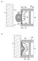
- (A) and (B) are cross-sectional views of a main part of the spacer of the third embodiment according to the present invention.
- (A) and (B) are cross-sectional views of a main part of the spacer of the fourth embodiment according to the present invention.
- (A) and (B) are cross-sectional views of a main part of the spacer according to the fifth embodiment of the present invention.
- (A) and (B) are cross-sectional views of a main part of the spacer of the sixth embodiment according to the present invention.
- (A) and (B) are cross-sectional views of a main part of the spacer of the seventh embodiment according to the present invention.
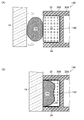
- Cross-sectional view showing a modified example of a spacer having two spaces are cross-sectional views of a main part of the spacer of the eighth embodiment according to the present invention.
- (A) and (B) are cross-sectional views of a main part of the spacer of the ninth embodiment according to the present invention.
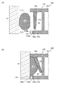
- (A) and (B) are cross-sectional views of a main part of the double glazing according to the tenth embodiment of the present invention.
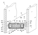
- FIG. 1 is a cross-sectional view of a main part of the double glazing 12 of the first embodiment in which the spacer 10 for double glazing of the first embodiment (hereinafter, abbreviated as “spacer 10”) is adopted.
- the double glazing 12 shown in FIG. 1 includes a spacer 10 having a longitudinal axis, two rectangular glass plates 14 and 16, an adhesive primary sealing material 18, and a secondary sealing material 20. There is.
- the double glazing 12 at least four spacers 10 are provided, and the ends of two adjacent spacers 10 out of the four spacers 10 are connected to each other via a corner key 50 (see FIG. 3) described later. Will be done.
- the four spacers 10 are assembled in a frame shape along the peripheral edges of the glass plates 14 and 16.
- the primary sealing material 18 is an example of the spacer sealing material of the present invention.
- the glass plates 14 and 16 have the same surface area and are separated by a spacer 10 assembled in a frame shape as described above. Both side surfaces of the spacer 10 facing the glass plate 14 and the glass plate 16 are adhered to the glass plate 14 and the glass plate 16 by the primary sealing materials 18 and 18. As a result, the hollow layer 22 is provided between the inner surface portion of the spacer 10 and the glass plate 14 and the glass plate 16. Then, the outer surface portion of the spacer 10 is filled with the secondary sealing material 20. As a result, the double glazing 12 is formed.
- the primary sealing material 18 butyl rubber can be exemplified
- the secondary sealing material 20 a polysulfide-based or silicone-based sealing material can be exemplified.
- the primary sealing material 18 and the secondary sealing material 20 may be made of the same material.
- another sealing material for protecting the secondary sealing material 20 may be provided on the outer surface portion of the secondary sealing material 20, and a stile member (not shown) is arranged in place of the secondary sealing material 20. May be adhered to the outer surface portion of the spacer 10.
- the spacer 10 is formed in the shape of a hollow pipe having a space 24 inside by extrusion molding with a synthetic resin material.
- the space 24 is filled with a desiccant 26 such as silica gel.
- the space portion 24 is provided along the longitudinal axis of the spacer 10.
- the inner surface portion of the spacer 10 is provided with a plurality of through holes 28 (see FIG. 2) at predetermined intervals along the longitudinal axis of the spacer 10.
- the desiccant 26 filled in the space 24 is exposed to the hollow layer 22 through these through holes 28, whereby the gas in the hollow layer 22 is dried.
- the fitting portion 54 see FIG.
- the corner key 50 is fitted into the opening of the space portion 24 provided at both ends of the spacer 10.
- the four spacers 10 are assembled in a frame shape as described above.
- an inert gas such as argon gas or krypton gas can be exemplified.
- FIG. 2 is an assembly perspective view of the double glazing 12 shown in FIG. 1, and shows a cross-sectional view of the glass plates 14 and 16 with respect to the spacer 10 before assembly.
- the spacer 10 includes a spacer main body 30, a pair of protruding portions 32 and 34 provided on both side surfaces of the spacer main body 30, and elastic bodies 36 and 36.
- the spacer main body 30 includes an inner surface portion 30A, a pair of side surface portions 30B and 30B connected to both sides of the inner surface portion 30A, and an outer surface portion 30C connected to the inner surface portions 30A of the pair of side surface portions 30B and 30B. , And the space portion 24 is surrounded by these four surface portions.
- the inner surface portion 30A is a flat surface facing the hollow layer 22 (see FIG. 1), and is provided with the above-mentioned through holes 28, 28.
- the pair of projecting portions 32, 34 are flat plate-shaped members integrally formed with the spacer main body 30, and are arranged so as to project from the side surface portion 30B in the in-plane direction of the inner surface portion 30A.
- the above-mentioned in-plane direction refers to a direction parallel to the flat surface of the inner surface portion 30A.
- the protruding portion 32 is formed on the same surface as the inner surface portion 30A and is arranged so as to project in the in-plane direction of the inner surface portion 30A.
- the inner surface portion of the spacer 10 is formed by a pair of projecting portions 32, 32 provided with the spacer main body 30 sandwiched therein, and an inner surface portion 30A of the spacer main body 30.
- the protruding portion 34 is formed on the same surface as the outer surface portion 30C parallel to the inner surface portion 30A, and is arranged so as to project in the in-plane direction of the outer surface portion 30C. As a result, a concave space 38 is formed between the pair of protruding portions 32 and 34 and the side surface portions 30B.
- the outer surface portion of the spacer 10 is formed by a pair of projecting portions 34, 34 provided with the spacer main body 30 sandwiched therein, and an outer surface portion 30C of the spacer main body 30.
- the protrusion amount of the protrusions 32 and 34 in the in-plane direction is configured so that the protrusion 32 is longer than the protrusion 34.
- the protruding portion 32 is an example of the second protruding portion of the present invention
- the protruding portion 34 is an example of the first protruding portion of the present invention.
- the elastic body 36 is a flat plate-shaped member or a fin-shaped member integrally formed with the protruding portion 34, and extends from the tip portion 34A of the protruding portion 34 toward the tip portion 32A of the protruding portion 32.
- the thick base end portion 36A is connected to the side surface portion 34B of the tip portion 34A
- the thin tip portion 36B of the elastic body 36 is the tip portion 32A. It is extended so as to be in contact with the outer surface portion 32B of the.
- the concave space 38 is closed by the elastic body 36.
- the elastic body 36 has a shape in which the cross-sectional shape in the direction from the tip portion 34A to the tip portion 32A becomes narrower.
- the elastic body 36 is formed so that the thickness decreases from the base end portion 36A toward the tip end portion 36B. As a result, the difference in the amount of protrusion of the protruding portions 32 and 34 is eliminated by the thickness of the elastic body 36.
- the elastic body 36 is integrally formed with the protruding portion 34, it may be integrally formed with the protruding portion 32, or may be integrally formed with both the protruding portions 32 and 34.
- the above-mentioned occlusion means a state in which the concave space 38 is completely closed by the elastic body 36, and at least the tip portion 36B although there is a very slight gap between the tip portion 36B and the outer surface portion 32B of the elastic body 36. Refers to a state in which a part of the surface is in contact with the outer surface portion 32B.
- the spacer main body 30 and the pair of protrusions 32 and 34 are formed of a hard synthetic resin material, and the elastic body 36 is formed of a soft material.
- the spacer body 30, the pair of protruding portions 32, 34, and the elastic body 36 are integrally molded by a two-color extrusion molding method.
- Examples of the synthetic resin material forming the spacer main body 30 and the pair of protrusions 32 and 34 include a hard vinyl chloride resin material, an acrylonitrile-styrene resin material, or a material containing a glass fiber material therein.
- the spacer body 30 and the pair of projecting portions 32, 34 are formed of a synthetic resin material, it is necessary to block the moisture entering the hollow layer 22 from the side of the pair of projecting portions 32, 34. Therefore, it is preferable to attach the moisture permeation prevention film 40 to the outer surface portion 30C of the spacer main body 30 and the side surface portion 36C of the elastic body 36.
- the moisture permeation prevention film 40 includes a metal coating film having moisture permeation prevention performance, a ceramic coating film, a composite coating film of metal and ceramic, a metal tape, or a moisture permeation prevention film made of a resin having moisture permeation prevention performance itself.
- a resin film can be exemplified.
- the metal coating film an aluminum coating film obtained by coating a plastic film carrier with aluminum having moisture permeation prevention performance by a means such as a vacuum vapor deposition method or a sputtering method can be exemplified.
- the ceramic coating film examples include a ceramic coating film in which a plastic film carrier is coated with a metal oxide (for example, SiO 2 ) having moisture permeation prevention performance by a means such as a vacuum vapor deposition method or a sputtering method.
- a metal oxide for example, SiO 2
- the metal tape examples include an aluminum metal tape and a stainless metal tape.
- the moisture permeation prevention resin film examples include a fluororesin film and a polyvinylidene chloride film.
- an elastomer typified by rubber or a cushion material such as urethane can be exemplified.
- the primary sealing material 18 is arranged on the side surface of the elastic body 36 via the moisture permeation prevention film 40. Since the primary sealing material 18 is a string-like body having a substantially circular cross-sectional shape and is arranged along the side surface of the elastic body 36, it is also arranged on the side surface portion of the corner key 50 (see FIG. 3). It is arranged on the spacer 10 side as one continuous adhesive material.
- the primary sealing material 18 arranged on the side surface of the left elastic body 36 becomes the glass plate 14 and the elastic body 36. It is plastically deformed while being sandwiched between and crushed. Then, as the crimping of the glass plate 14 is continued, the tip portion 36B of the elastic body 36 is elastically deformed toward the left side surface portion 30B with the base end portion 36A as a fulcrum by being pushed by the primary sealing material 18. .. Then, when the glass plate 14 is completely crimped to the left side surface portion of the spacer 10 (see FIG.
- the primary sealing material 18 fills a space having a substantially triangular cross-sectional shape surrounded by the glass plate 14 and the elastic body 36. It plastically deforms like this. Then, the primary sealing material 18 adheres the glass plate 14 and the spacer 10 in this shape. That is, the primary sealing material 18 plastically deforms from a state in which the cross-sectional shape is substantially circular to a state in which the cross section is substantially triangular, thereby adhering the glass plate 14 and the spacer body 30.
- the primary sealing material 18 arranged on the elastic body 36 on the right side is also deformed by crimping the glass plate 16 to bond the glass plate 16 and the spacer 10.
- the elastic body 36 is elastically deformed by an amount corresponding to the coating amount. That is, although the area of the substantially triangular shape is smaller than that of the specified amount, there is no gap in the space surrounded by the glass plate 14 and the elastic body 36. This solves the problem that the spacer 10 and the glass plates 14 and 16 have poor adhesion.
- the elastic body 36 is elastically deformed by an amount corresponding to the coating amount, so that the above-mentioned substantially triangular shape is compared with the specified amount.
- the area of is large.
- the spacer 10 of the first embodiment absorbs the error of the coating amount of the primary sealing material 18 by the deformation amount of the elastic body 36, so that strict adjustment is not required for the coating amount of the primary sealing material 18.
- the spacer body 30, the pair of projecting portions 32, 34, and at least one of the pair of projecting portions 32, 34 are connected to the projecting portion 34. Since the elastic body 36 that closes the concave space 38 is provided, the amount of the primary sealing material 18 applied to the spacer 10 can be easily adjusted.
- the thickness of the primary sealing material 18 that contributes to adhesion is secured, whereby the coating amount of the primary sealing material 18 is secured.
- the primary sealing material 18 is arranged on the elastic body 36 deformed toward the side surface portion 30B, the primary sealing material 18 follows the deformation of the glass plates 14 and 16 due to the expansion or contraction of the hollow layer 22. This also has the advantage of improving the durability of the double glazing 12.
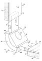
- FIG. 3 is a perspective view showing a state immediately before the ends of the two spacers 10 and 10 are connected to the corner key 50.
- the corner key 50 is a part that constitutes the corner portion of the spacer 10, and is, for example, a part manufactured by resin molding.
- the corner key 50 has a main body block 52 and two fitting portions 54 and 54 extending from end faces 58A and 58B of the main body block 52 that are orthogonal to each other.
- the space portions 24 see FIGS. 1 and 2
- the two adjacent spacers 10 and 10 The ends are connected to each other in the perpendicular direction via the corner key 50.
- the main body block 52 is provided with a through hole 56 penetrating from the outer end face to the inner end face of the main body block 52.
- the through hole 56 is used as an injection hole for injecting the inert gas into the hollow layer 22 (see FIG. 1).
- the side surface portions 60 on both sides of the main body block 52 are provided with a groove 62 for a sealing material.
- the sealing material groove 62 is a groove in which the primary sealing material 18 (see FIG. 2) is arranged, and is formed as a curved groove in which the end face 58A and the end face 58B of the main body block 52 are communicated with each other.
- the sealing material groove 62 has a longitudinal axis connecting the end face 58A and the end face 58B, and this longitudinal axis is referred to as a forming direction.
- the cross-sectional shape in the direction orthogonal to the forming direction of the sealing material groove 62 is formed into a substantially triangular shape having the same cross-sectional shape as the primary sealing material 18 shown in FIG. 1 and the same cross-sectional area. That is, it is formed in a shape equal to the shape of the elastic body 36 that is elastically deformed in the concave space 38.
- the bottom of the sealing material groove 62 is provided with a concave pocket 64 for accommodating a surplus portion of the primary sealing material 18. Even when a large number of primary sealing materials 18 are arranged in the sealing material grooves 62, the excess portion is accommodated in the pocket 64. As a result, it is prevented that the primary sealing material 18 leaks from the sealing material groove 62 and protrudes to the hollow layer 22 side.
- FIG. 4 is an explanatory view of a corner portion of the double glazing 12.
- the primary sealing material 18 arranged along the forming direction of the sealing material groove 62 is pushed by the glass plate 14 for the sealing material. It deforms into a shape along the groove 62. Then, when the glass plate 14 is completely crimped to the left side surface portion of the spacer 10 (see FIG. 1), that is, when the glass plate 14 is completely crimped to the left side surface portion of the main body block 52, the primary sealing material 18 is released.
- the cross-sectional shape surrounded by the glass plate 14 and the groove 62 for the sealing material is plastically deformed so as to fill a substantially triangular space, and the glass plate 14 and the main body block 52 are bonded to each other in this shape. That is, the primary sealing material 18 arranged in the sealing material groove 62 is plastically deformed into a substantially triangular shape having the same appearance shape and the same cross-sectional area as the primary sealing material 18 arranged in the elastic body 36.
- the corner key 50 is provided with the groove 62 for the sealing material, the primary sealing material 18 when the double glazing 12 is formed as shown in FIG. Has a uniform cross-sectional shape over the entire circumference of the primary sealing material 18. As a result, the adhesiveness of the glass plates 14 and 16 to the spacer 10 and the corner key 50 is improved.
- the shape of the sealing material groove 62 is not limited to the above shape, and may be any shape that can accommodate the primary sealing material 18. As a result, it is possible to solve the design problem that the primary sealing material 18 protrudes to the hollow layer 22 side.
- FIG. 5 (A) and 5 (B) are cross-sectional views of a main part of the spacer 70 of the second embodiment.
- FIG. 5 (A) is a cross-sectional view of a main part showing a state immediately before the glass plate 14 is adhered to the left side surface portion of the spacer 70
- FIG. 5 (B) is a left side surface portion of the spacer 70. It is sectional drawing of the main part which showed the state which the glass plate 14 was adhered.
- members that are the same as or similar to the spacer 10 shown in FIG. 2 will be described with the same reference numerals.
- the spacer 70 shown in FIGS. 5A and 5B has a protruding portion 72 and a protruding portion 74 having the same length in the in-plane direction of the inner surface portion 30A, and the elastic body 76 is the tip of the protruding portion 74. It extends from the portion 74A toward the tip portion 72A of the protruding portion 72.
- the elastic body 76 is formed to have a uniform thickness, the base end portion 76A of the elastic body 76 is connected to the inner surface portion 74B of the tip portion 74A, and the tip portion 76B of the elastic body 76 is connected. It is connected to the outer surface portion 72B of the tip portion 72A.
- the outer surface portion 76C of the elastic body 76 is arranged on the same surface as the side surface portion 74C of the tip portion 74A and the side surface portion 72C of the tip portion 72A.
- the protruding portion 72 is an example of the first protruding portion of the present invention
- the protruding portion 74 is an example of the second protruding portion of the present invention.
- the elastic body 76 of this example is integrally molded with the protruding portions 72 and 74, it may be integrally molded with at least one of the protruding portions 72 and 74.
- the primary sealing material 18 arranged on the side surface of the left elastic body 76 is elastic with the glass plate 14. It is sandwiched between the body 76 and plastically deformed while being crushed. Then, as the crimping of the glass plate 14 is continued, as shown in FIG. 5B, the central portion 76D of the elastic body 76 is elastically deformed toward the left side surface portion 30B by being pushed by the primary sealing material 18. I will go.
- the primary sealing material 18 is plastically deformed so that the cross-sectional shape surrounded by the glass plate 14 and the elastic body 76 fills a substantially triangular space.
- the glass plate 14 and the spacer 70 are adhered to each other in this shape.
- the elastic body 76 is elastically deformed by an amount corresponding to the coating amount. That is, although the area of the substantially triangular shape is smaller than that of the specified amount, there is no gap in the space surrounded by the glass plate 14 and the elastic body 76. This solves the problem that the spacer 70 and the glass plates 14 and 16 have poor adhesion.
- the elastic body 76 is elastically deformed by an amount corresponding to the coating amount, so that the above triangular shape is compared with the specified amount. The area becomes large. As a result, the problem that the primary sealing material 18 protrudes to the hollow layer 22 side of the double glazing 12 can be solved.
- the error in the coating amount of the primary sealing material 18 is absorbed by the deformation amount of the elastic body 76, so that the coating amount of the primary sealing material 18 on the spacer 70 is similar to the spacer 10. Is easy to adjust.
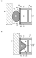
- FIG. 6A and 6 (B) are cross-sectional views of a main part of the spacer 80 of the third embodiment.
- FIG. 6A is a cross-sectional view of a main part showing a state immediately before the glass plate 14 is adhered to the left side surface portion of the spacer 80
- FIG. 6B is a left side surface portion of the spacer 80. It is sectional drawing of the main part which showed the state which the glass plate 14 was adhered.
- members that are the same as or similar to the spacer 10 shown in FIG. 2 will be described with the same reference numerals.
- the spacer 80 shown in FIGS. 6A and 6B has a protruding portion 82 and a protruding portion 84 having the same length in the in-plane direction of the inner surface portion 30A, and the elastic body 86 is the tip of the protruding portion 84. It extends from the portion 84A toward the tip portion 82A of the protruding portion 82.
- the elastic body 86 is formed to have a uniform thickness, the base end portion 86A of the elastic body 86 is connected to the side surface portion 84B of the tip portion 84A, and the tip portion 86B of the elastic body 86 is connected. It is connected to the side surface portion 82B of the tip portion 82A.
- the protruding portion 82 is an example of the first protruding portion of the present invention
- the protruding portion 84 is an example of the second protruding portion of the present invention.
- the elastic body 86 of this example is integrally molded with the protrusions 82 and 84, it may be integrally molded with at least one of the protrusions 82 and 84.
- the primary sealing material 18 arranged on the side surface of the left elastic body 86 is elastic with the glass plate 14. It is sandwiched between the body 86 and crushed while being plastically deformed. Then, as the crimping of the glass plate 14 is continued, as shown in FIG. 6B, the central portion 86C of the elastic body 86 is elastically deformed toward the left side surface portion 30B by being pushed by the primary sealing material 18. I will go.
- the primary sealing material 18 is plastically deformed so that the cross-sectional shape surrounded by the glass plate 14 and the elastic body 86 fills a substantially triangular space.
- the glass plate 14 and the spacer 80 are adhered to each other in this shape.
- the spacer 80 configured in this way, the error in the coating amount of the primary sealing material 18 is absorbed by the deformation amount of the elastic body 86, so that the primary sealing material 18 is applied to the spacer 80 in the same manner as the spacers 10 and 70.
- the amount can be easily adjusted.
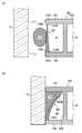
- FIG. 7 (A) and 7 (B) are cross-sectional views of a main part of the spacer 90 of the fourth embodiment.
- FIG. 7A is a cross-sectional view of a main part showing a state immediately before the glass plate 14 is adhered to the left side surface portion of the spacer 90
- FIG. 7B is a left side surface portion of the spacer 90. It is sectional drawing of the main part which showed the state which the glass plate 14 was adhered.
- members that are the same as or similar to the spacer 10 shown in FIG. 2 will be described with the same reference numerals.
- the spacer 90 shown in FIGS. 7A and 7B has a protrusion 92 and a protrusion 94 having the same length in the in-plane direction of the inner surface portion 30A, and the elastic body 96 is the tip of the protrusion 94. It extends from the portion 94A toward the tip portion 92A of the protruding portion 92.
- the elastic body 96 is formed to have a uniform thickness, the base end portion 96A of the elastic body 96 is connected to the inner surface portion 94B of the tip portion 94A, and the tip portion 96B of the elastic body 96 is connected. It is connected to the outer surface portion 92B of the tip portion 92A.
- the elastic body 96 is arranged so as to be displaced from the side surface portion 92C of the tip portion 92A and the side surface portion 94C of the tip portion 94A to the side surface portion 30B side.
- the protruding portion 92 is an example of the first protruding portion of the present invention
- the protruding portion 94 is an example of the second protruding portion of the present invention.
- the elastic body 96 of this example is integrally molded with the protruding portions 92 and 94, it may be integrally molded with at least one of the protruding portions 92 and 94.
- the primary sealing material 18 with respect to the spacer 90 is similar to the spacers 10, 70, and 80. It becomes easy to adjust the coating amount of.
- FIG. 8 (A) and 8 (B) are cross-sectional views of a main part of the spacer 100 of the fifth embodiment.
- FIG. 8A is a cross-sectional view of a main part showing a state immediately before the glass plate 14 is adhered to the left side surface portion of the spacer 100
- FIG. 8B is a left side surface portion of the spacer 100. It is sectional drawing of the main part which showed the state which the glass plate 14 was adhered.
- members that are the same as or similar to the spacer 10 shown in FIG. 2 will be described with the same reference numerals.
- the spacer 100 shown in FIGS. 8A and 8B has a protruding portion 102 and a protruding portion 104 having the same length in the in-plane direction of the inner surface portion 30A.
- the elastic body 106 is integrally formed with the protruding portion 104, and extends from the tip portion 104A of the protruding portion 104 toward the tip portion 102A of the protruding portion 102.
- the thick base end portion 106A is connected to the inner surface portion 104B of the tip portion 104A
- the thin tip portion 106B of the elastic body 106 is the tip portion 102A. It is extended so as to be in contact with the outer surface portion 102B of the.
- the protruding portion 102 is an example of the first protruding portion of the present invention
- the protruding portion 104 is an example of the second protruding portion of the present invention.
- the elastic body 106 of this example is integrally molded with the protruding portion 104, it may be integrally molded with at least one of the protruding portions 102 and 104.
- the spacer 100 configured in this way, the error in the coating amount of the primary sealing material 18 is absorbed by the deformation amount of the elastic body 106, so that the primary sealing with respect to the spacer 100 is similar to the spacers 10, 70, 80, 90.
- the coating amount of the material 18 can be easily adjusted.
- FIG. 9 (A) and 9 (B) are cross-sectional views of a main part of the spacer 110 of the sixth embodiment.
- FIG. 9A is a sectional view of a main part showing a state immediately before the glass plate 14 is adhered to the left side surface portion of the spacer 110
- FIG. 9B is a left side surface portion of the spacer 110. It is sectional drawing of the main part which showed the state which the glass plate 14 was adhered.
- members that are the same as or similar to the spacer 10 shown in FIG. 2 will be described with the same reference numerals.
- the spacer 110 shown in FIGS. 9A and 9B has a protruding portion 112 and a protruding portion 114 having the same length in the in-plane direction of the inner surface portion 30A.
- the elastic body 116 is integrally formed with the protruding portion 112, and extends from the tip portion 112A of the protruding portion 112 toward the tip portion 114A of the protruding portion 114.
- the thick base end portion 116A is connected to the outer surface portion 112B of the tip portion 112A
- the thin tip portion 116B of the elastic body 116 is the tip portion 114A. It is extended so as to be in contact with the inner surface portion 114B of the.
- the protruding portion 112 is an example of the first protruding portion of the present invention
- the protruding portion 114 is an example of the second protruding portion of the present invention.
- the elastic body 116 of this example is integrally molded with the protruding portion 112, it may be integrally molded with at least one of the protruding portions 112 and 114.
- the spacer 110 configured in this way, since the error in the coating amount of the primary sealing material 18 is absorbed by the deformation amount of the elastic body 116, the spacer 110 is similarly subjected to the same as the spacers 10, 70, 80, 90, 100. The coating amount of the primary sealing material 18 can be easily adjusted.
- FIG. 10A and 10 (B) are cross-sectional views of a main part of the spacer 120 of the seventh embodiment.
- FIG. 10A is a cross-sectional view of a main part showing a state immediately before the glass plate 14 is adhered to the left side surface portion of the spacer 120
- FIG. 10B is a left side surface portion of the spacer 120. It is sectional drawing of the main part which showed the state which the glass plate 14 was adhered.
- members that are the same as or similar to the spacer 10 shown in FIG. 2 will be described with the same reference numerals.
- the spacer 120 shown in FIGS. 10A and 10B has a protruding portion 122 and a protruding portion 124 having the same length in the in-plane direction of the inner surface portion 30A.
- the elastic body includes an elastic body 126 provided at the tip portion 122A of the protruding portion 122, and an elastic body 128 provided at the tip portion 124A of the protruding portion 124.
- the elastic body 126 is integrally formed with the protruding portion 122 and extends from the tip portion 122A toward the tip portion 124A. Specifically, the elastic body 126 has a shape in which the cross-sectional shape in the direction from the tip portion 122A to the tip portion 124A becomes narrower, and the thick base end portion 126A is connected to the outer surface portion 122B of the tip portion 122A. Has been done.
- the elastic body 128 is integrally formed with the protruding portion 124, and extends from the tip portion 124A toward the tip portion 122A. Specifically, the elastic body 128 has a shape in which the cross-sectional shape in the direction from the tip portion 124A to the tip portion 122A becomes narrower, and the thick base end portion 128A is connected to the inner surface portion 124B of the tip portion 124A. Has been done.
- the elastic bodies 126 and 128 are arranged so that the tip portions 126B and 128B, which are the tops of each other, face each other. The tip portions 126B and 128B may be separated from each other, in contact with each other, or connected to each other.
- the protruding portion 122 is an example of the first protruding portion of the present invention
- the protruding portion 124 is an example of the second protruding portion of the present invention
- the elastic body 126 is an example of the first elastic body of the present invention
- the elastic body 128 is an example of the second elastic body of the present invention.
- the primary sealing material 18 arranged on the side surfaces of the elastic bodies 126 and 128 on the left side is the glass plate 14. Is sandwiched between the elastic bodies 126 and 128 and is crushed while being plastically deformed. Then, as the crimping of the glass plate 14 is continued, the tip portion 126B of the elastic body 126 and the tip portion 128B of the elastic body 128 are pushed by the primary sealing material 18 with the respective base end portions 126A and 128A as fulcrums. It elastically deforms toward the left side surface portion 30B. Then, as shown in FIG.
- the primary sealing material 18 when the glass plate 14 is completely crimped to the left side surface portion of the spacer 120, the primary sealing material 18 has a substantially cross-sectional shape surrounded by the glass plate 14 and the elastic bodies 126 and 128. It is plastically deformed so as to fill the triangular space, and the glass plate 14 and the spacer 120 are bonded in this shape.
- the elastic bodies 126 and 128 of this example have a shape in which the cross-sectional shape becomes thin as described above, but the shape is not limited to this shape, and may be, for example, a flat plate shape having a uniform thickness.
- FIG. 11 is a cross-sectional view showing a modified example of the spacer 130 provided with the two space portions 24, 24.
- the spacer 130 shown in FIG. 11 is applied to a double glazing having a multilayer structure including three or more glass plates. Specifically, the glass plates 14 and 16 indicated by the alternate long and short dash lines are adhered to the spacer 130 by the primary sealing materials 18 and 18 arranged on the elastic bodies 36 and 36.
- the inner surface portion of the spacer 130 is provided with a concave holding portion 134 that holds the end portion of the intermediate glass plate 132 indicated by the alternate long and short dash line.
- a base member 136 on which the end portion of the intermediate glass plate 132 is supported is arranged at the bottom portion of the holding portion 134.
- the base member 136 is made of a soft material such as a cushioning material or an elastic material.
- both walls of the holding portion 134 are provided with lip portions 138 and 138 that sandwich the peripheral portion of the intermediate glass plate 132.
- the lip portions 138 and 138 are also made of a soft material and are integrally molded with the spacer 130.
- the spacer 130 shown in FIG. 11 is also assembled in a frame shape by a corner key (not shown) having a pair of fitting portions fitted to the space portions 24, 24. Further, if the spacer is provided with a plurality of holding portions 134, it can be applied to double glazing having four or more glass plates. That is, the spacer of the present invention can be used for double glazing having three or more glass plates.
- FIG. 12A and 12 (B) are cross-sectional views of a main part of the spacer 140 of the eighth embodiment.
- FIG. 12A is a cross-sectional view of a main part showing a state immediately before the glass plate 14 is adhered to the left side surface portion of the spacer 140
- FIG. 12B is a left side surface portion of the spacer 140. It is sectional drawing of the main part which showed the state which the glass plate 14 was adhered.
- members that are the same as or similar to the spacer 10 shown in FIG. 2 will be described with the same reference numerals.
- the spacer 140 shown in FIGS. 12A and 12B has a pair of protruding portions 32, 34 having the same length in the in-plane direction of the inner surface portion 30A, and the pair of protruding portions 32, 34 and the side surface portion 30B.
- the elastic body 142 is arranged in the concave space 38 between the two.
- the elastic body 142 is a rod-shaped body having a longitudinal axis, and has a rectangular cross-sectional shape in a direction orthogonal to the longitudinal axis. By being fitted into the concave space 38, the elastic body 142 is arranged in the concave space 38 in a state of being elastically deformed along the contour shape of the concave space 38.
- the elastic body 142 is made of, for example, a foam made of polyethylene having elasticity.
- the primary sealing material 18 arranged on the side surface of the left elastic body 142 is elastic with the glass plate 14. It is sandwiched between the body 142 and crushed while being plastically deformed. Then, as the crimping of the glass plate 14 is continued, the elastic body 142 is elastically deformed toward the side surface portion 30B by being pushed by the primary sealing material 18. Then, as shown in FIG. 12B, when the glass plate 14 is completely crimped to the left side surface portion of the spacer 140, the primary sealing material 18 fills the space surrounded by the elastically deformed elastic body 142 and the glass plate 14. The glass plate 14 and the spacer 140 are bonded to each other in this shape by plastic deformation.
- the spacer 140 to which the foam material arranged in the concave space 38 as the elastic body 142 is applied, the error of the coating amount of the primary sealing material 18 is absorbed by the deformation amount of the elastic body 142, so that the spacer It becomes easy to adjust the coating amount of the primary sealing material 18 with respect to 140.
- FIG. 13 (A) and 13 (B) are cross-sectional views of a main part of the spacer 150 of the ninth embodiment.
- FIG. 13A is a cross-sectional view of a main part showing a state immediately before the glass plate 14 is adhered to the left side surface portion of the spacer 150
- FIG. 13B is a left side surface portion of the spacer 150. It is sectional drawing of the main part which showed the state which the glass plate 14 was adhered.
- members that are the same as or similar to the spacer 10 shown in FIG. 2 will be described with the same reference numerals.
- the spacer 150 shown in FIGS. 13A and 13B has a pair of projecting portions 32, 34 having the same length in the in-plane direction of the inner surface portion 30A, and the pair of projecting portions 32, 34 and the side surface portion 30B.
- the elastic body 152 is arranged in the concave space 38 between the two.
- the elastic body 152 has a longitudinal axis, and is composed of a tube tube having a ring-shaped cross section in a direction orthogonal to the longitudinal axis.
- the elastic body 152 is placed in the concave space 38 in a state of being elastically deformed along the contour shape of the concave space 38 by being fitted into the concave space 38.
- the elastic body 152 is made of rubber as an example.
- the primary sealing material 18 arranged on the side surface of the left elastic body 152 is elastic with the glass plate 14. It is sandwiched between the body 152 and crushed while being plastically deformed. Then, as the crimping of the glass plate 14 is continued, the elastic body 152 is elastically deformed toward the side surface portion 30B by being pushed by the primary sealing material 18. Then, as shown in FIG. 13B, when the glass plate 14 is completely crimped to the left side surface portion of the spacer 150, the primary sealing material 18 fills the space surrounded by the elastically deformed elastic body 152 and the glass plate 14. The glass plate 14 and the spacer 150 are bonded to each other in this shape by plastic deformation.
- the spacer 150 having the tube tube arranged in the concave space 38 as the elastic body 152 in this way the error in the coating amount of the primary sealing material 18 is absorbed by the deformation amount of the elastic body 152. , The amount of the primary sealing material 18 applied to the spacer 150 can be easily adjusted.
- FIG. 14 (A) and 14 (B) are cross-sectional views of a main part showing the configuration of the double glazing 160 of the tenth embodiment
- FIG. 14 (A) is a left side surface of the spacer 170 of the tenth embodiment
- FIG. 14B is a cross-sectional view of a main part showing a state immediately before the glass plate 14 is attached to the portion
- FIG. 14B is a cross-sectional view of the main part showing a state in which the glass plate 14 is attached to the left side surface portion of the spacer 170. is there.
- the same members as those of the double glazing 12 shown in FIG. 1 or similar members are designated by the same reference numerals, and the description thereof will be omitted.
- the double glazing 160 shown in FIGS. 14A and 14B has a plurality of spacers 170, and the ends of the plurality of spacers 170 are connected to each other via a corner key (not shown) in a frame shape. At least two glass plates 14 (glass plates 16 are not shown) are separated by spacers. Then, the spacer 170 and the glass plate 14 are adhered to each other by the primary sealing material 18 arranged on the elastic body 174 of the spacer main body 172.
- the elastic body 174 is integrally formed with one 180 of the protrusions 178 and 180 constituting the spacer 170, and extends from the tip end portion of the one protrusion 180 toward the tip end portion of the other protrusion 178.
- the thick base end portion is connected to the outer surface portion of the tip portion of one protruding portion 180, and the thin tip portion of the elastic body 174 is the other. It is extended so that there is a gap between it and the inner surface of the tip of the protruding portion.
- a fin-shaped member is applied as the elastic body 174, but the present invention is not limited to this, and FIGS.
- the foam shown in B) may be used, or the tube tube shown in FIGS. 13 (A) and 13 (B) may be used.
- the double glazing 160 is provided with a weir member 176 between the spacer 170 and the glass plate 14 to prevent the primary sealing material 18 from protruding from the spacer 170 to the outside.
- the weir member 176 is arranged in the protruding portion 178 arranged outside the double glazing 160 among the protruding portion 178 and the protruding portion 180 constituting the spacer 170.
- the protruding portion 178 is configured to have a shorter protruding amount than the protruding portion 180, and the weir member 176 is arranged along the side surface portion 178A of the protruding portion 178.
- the side surface portion 176A on the spacer 170 side of the weir member 176 is adhered to the side surface portion 178A, and the side surface portion 176B on the glass plate 14 side of the weir member 176 is adhered or crimped to the glass plate 14. Further, the width dimension of the weir member 176 (the dimension between the side surface portion 176A and the side surface portion 176B) corresponds to the difference in length between the protrusion 178 and the protrusion 180.
- the primary sealing material 18 is dammed by the weir member 176.
- the primary sealing material 18 can be prevented from protruding from the spacer 170 to the outside, so that the durability of the double glazing 160 is improved.
- the weir member 176 described in the present embodiment is a long member arranged along the side surface portion 178A of the projecting portion 178, and the cross-sectional shape is preferably rectangular from the viewpoint of preventing the protrusion. May have other shapes, such as circular. Further, the weir member 176 may be made of a structural sealing material such as a silicone-based sealing material or a polysulfide-based sealing material, or may be made of a resin.
- the elastic body of the fin-shaped member which is the constituent member of the present invention is not limited to the one formed of a soft material, and can be applied to a thin plate made of a hard synthetic resin material, and has a thickness. It can be applied even if it is composed of a thin metal film. That is, the elastic body which is a constituent member of the present invention can be applied as long as it is pressed by the spacer sealing material and elastically deforms into the concave space.
- the spacer main body and the pair of projecting portions, which are the constituent members of the present invention are not limited to those made of synthetic resin, and may be made of metal such as aluminum.
- the entire contents of the specification, scope of patent claims, drawings and abstract of Japanese Patent Application No. 2019-218044 are cited herein and incorporated as disclosure of the specification of the present invention.
Landscapes
- Chemical & Material Sciences (AREA)
- Engineering & Computer Science (AREA)
- Ceramic Engineering (AREA)
- Life Sciences & Earth Sciences (AREA)
- Chemical Kinetics & Catalysis (AREA)
- General Chemical & Material Sciences (AREA)
- Geochemistry & Mineralogy (AREA)
- Materials Engineering (AREA)
- Organic Chemistry (AREA)
- Civil Engineering (AREA)
- Structural Engineering (AREA)
- Securing Of Glass Panes Or The Like (AREA)
- Joining Of Glass To Other Materials (AREA)
Abstract
複層ガラス用スペーサに対するスペーサ用シール材の塗布量の調整が容易な複層ガラス用スペーサ及び複層ガラスを提供する。 本発明のスペーサ10は、スペーサ本体30と、一対の突出部32、34と、一対の突出部32、34のうち少なくとも一方の突出部34に連接されて凹状空間38を閉塞する弾性体36と、を有する。
Description
本発明は、複層ガラス用スペーサ及び複層ガラスに関する。
特許文献1、2には、ガラス板と接するスペーサの側面部に凹部が備えられ、この凹部に接着剤や1次封着材を充填したスペーサ及び複層ガラスが開示されている。
特許文献1によれば、上記の凹部に接着剤を充填することにより、スペーサの側面部とガラス板の周縁部との接着を容易に行うことができ、かつ接着効果を増大できる、というものである。
また、特許文献2によれば、上記の凹部に1次封着材を担持し易くなる、というものである。
しかしながら、特許文献1、2に開示された従来のスペーサは、凹部の容積に比して接着剤や1次封着材(以下、スペーサ用シール材と言う。)の塗布量が少ない場合には、凹部にスペーサ用シール材の未充填部が生じるので、スペーサとガラス板とが接着不良になるという問題があった。また、凹部の容積に比してスペーサ用シール材の塗布量が多い場合には、ガラス板をスペーサの側面部に圧着した際にスペーサ用シール材が凹部から漏出して複層ガラスの中空層側にはみ出る場合があるので、複層ガラスの意匠的な見栄えが悪くなるという問題があった。
このように従来のスペーサは、スペーサ(以下、複層ガラス用スペーサと言う。)に対するスペーサ用シール材の塗布量の調整が難しいという問題があった。
本発明は、このような事情に鑑みてなされたもので、複層ガラス用スペーサに対するスペーサ用シール材の塗布量の調整が容易な複層ガラス用スペーサ及び複層ガラスを提供することを目的とする。
本発明の複層ガラス用スペーサは、本発明の目的を達成するために、長手軸を有し、少なくとも2枚のガラス板を互いに隔置して配置する複層ガラス用スペーサであって、内面部と、内面部の両側に連接された一対の側面部と、一対の側面部の内面部と反対側に連接された外面部とを有するスペーサ本体と、一対の側面部から内面部の面内方向に突出された一対の突出部であって、側面部との間で凹状空間を形成する一対の突出部と、凹状空間に配置された弾性体と、を有する。
本発明の複層ガラスは、本発明の目的を達成するために、本発明の複層ガラス用スペーサを複数本備え、複数本の複層ガラス用スペーサの端部同士を、コーナーキーを介して接続してなる枠状スペーサによって少なくとも2枚のガラス板が隔置され、スペーサ本体の弾性体に配置されたスペーサ用シール材によってスペーサ本体と2枚のガラス板とが接着された複層ガラスであって、コーナーキーには、スペーサ用シール材が配置されるシール材用溝が備えられる。
本発明の複層ガラスは、本発明の目的を達成するために、本発明の複層ガラス用スペーサを複数本備え、複数本の複層ガラス用スペーサの端部同士を、コーナーキーを介して接続してなる枠状スペーサによって少なくとも2枚のガラス板が隔置され、スペーサ本体の弾性体に配置されたスペーサ用シール材によってスペーサ本体と2枚のガラス板とが接着された複層ガラスであって、スペーサ本体と2枚のガラス板との間には、スペーサ用シール材が複層ガラス用スペーサから外側へはみ出すことを防止する堰部材が備えられる。
本発明によれば、複層ガラス用スペーサに対するスペーサ用シール材の塗布量の調整が容易になる。
以下、添付図面に従って本発明に係る複層ガラス用スペーサ及び複層ガラスの好ましい実施形態を説明する。
図1は、第1実施形態の複層ガラス用スペーサ10(以下、「スペーサ10」と略称する。)が採用された第1実施形態の複層ガラス12の要部断面図である。
図1に示す複層ガラス12は、長手軸を有するスペーサ10と、矩形の2枚のガラス板14、16と、接着性を有する一次シール材18と、二次シール材20と、を備えている。複層ガラス12においては、スペーサ10は少なくとも4本備えられ、4本のスペーサ10のうち隣接する2本のスペーサ10の端部同士が、後述するコーナーキー50(図3参照)を介して接続される。これにより、4本のスペーサ10は、ガラス板14、16の周縁部に沿った枠状に組み立てられる。ここで、上記の一次シール材18は、本発明のスペーサ用シール材の一例である。
ガラス板14、16は表面積が等しく、上記のように枠状に組み立てられたスペーサ10を介して隔置される。ガラス板14とガラス板16とに対向するスペーサ10の両側面部が、一次シール材18、18によってガラス板14とガラス板16とに接着される。これにより、スペーサ10の内面部とガラス板14とガラス板16との間に中空層22が備えられる。そして、スペーサ10の外面部に二次シール材20が充填される。これによって、複層ガラス12が構成される。
一次シール材18としてはブチルゴムを例示でき、二次シール材20としてはポリサルファイド系又はシリコーン系のシーリング材を例示できる。なお、一次シール材18及び二次シール材20は、同一の材料としてもよい。また、二次シール材20の外面部に二次シール材20を保護する別のシール材を備えてもよく、二次シール材20に代えて框部材(不図示)を配置し、この框部材をスペーサ10の外面部に接着してもよい。
スペーサ10の詳細な構造については後述するが、スペーサ10は一例として、合成樹脂材による押出成形により内部に空間部24を有する中空のパイプ状に構成される。空間部24には、シリカゲル等の乾燥剤26が充填される。空間部24は、スペーサ10の長手軸に沿って備えられている。また、スペーサ10の内面部には、スペーサ10の長手軸に沿って複数の貫通孔28(図2参照)が所定の間隔で備えられている。空間部24に充填された乾燥剤26は、これらの貫通孔28を介して中空層22に露出され、これによって中空層22の気体が乾燥される。なお、スペーサ10の両端部に備えられた空間部24の開口部にコーナーキー50の嵌合部54(図3参照)が嵌合される。これにより、4本のスペーサ10が上記の如く枠状に組み立てられる。また、中空層22に充填される気体としては、アルゴンガス又はクリプトンガス等の不活性ガスを例示できる。このような不活性ガスを中空層22に充填することにより、断熱性を備えた複層ガラス12を提供できる。
図2は、図1に示した複層ガラス12の組立斜視図であり、スペーサ10に対するガラス板14、16の組立前の状態が断面図として示されている。まず、図2を用いてスペーサ10の詳細な構造について説明する。
スペーサ10は、スペーサ本体30と、スペーサ本体30の両側面部に備えられた一対の突出部32、34と、弾性体36、36と、を備えている。
スペーサ本体30は、内面部30Aと、内面部30Aの両側に連接された一対の側面部30B、30Bと、一対の側面部30B、30Bの内面部30Aと反対側に連接された外面部30Cと、を有し、これらの4つの面部によって空間部24を包囲している。
内面部30Aは、中空層22(図1参照)に対向した平坦面であり、前述した貫通孔28、28が備えられている。
一対の突出部32、34は、スペーサ本体30と一体形成された平板状部材であり、側面部30Bから内面部30Aの面内方向に突出して配置されている。ここで、上記の面内方向とは、内面部30Aの平坦面と平行な方向を指す。
突出部32は、内面部30Aと同一面上に形成されて内面部30Aの面内方向に突出して配置されている。なお、スペーサ本体30を挟んで備えられた一対の突出部32、32と、スペーサ本体30の内面部30Aとによってスペーサ10の内面部が構成されている。
突出部34は、内面部30Aと平行な外面部30Cと同一面上に形成されて外面部30Cの面内方向に突出して配置されている。これにより、一対の突出部32、34と側面部30Bとの間に凹状空間38が形成される。なお、スペーサ本体30を挟んで備えられた一対の突出部34、34と、スペーサ本体30の外面部30Cとによってスペーサ10の外面部が構成されている。
また、上記の面内方向における突出部32、34の突出量は、突出部34よりも突出部32が長くなるように構成されている。ここで、突出部32は、本発明の第2突出部の一例であり、突出部34は、本発明の第1突出部の一例である。
弾性体36は、突出部34と一体形成された平板状部材若しくはヒレ状部材であり、突出部34の先端部34Aから突出部32の先端部32Aに向けて延設されている。具体的に説明すると、弾性体36は、厚さの厚い基端部36Aが、先端部34Aの側面部34Bに連接されており、弾性体36の厚さの薄い先端部36Bが、先端部32Aの外面部32Bに接するように延設される。これにより、弾性体36によって凹状空間38が閉塞されている。また、弾性体36は、先端部34Aから先端部32Aに向かう方向の断面形状が細くなる形状を有している。つまり、弾性体36は、基端部36Aから先端部36Bに向かうに従って厚さが薄くなるように形成されている。これにより、突出部32、34の突出量の差分が弾性体36の厚さによって解消されている。なお、上記の弾性体36は、突出部34と一体形成された態様であるが、突出部32と一体形成された態様でもよく、双方の突出部32、34と一体形成された態様でもよい。ここで、上記の閉塞とは、弾性体36によって凹状空間38を完全に閉塞した状態、及び弾性体36の先端部36Bと外面部32Bとの間に極僅かな隙間はあるが少なくとも先端部36Bの一部が外面部32Bに接している状態を指す。
上記のように構成されたスペーサ10は、例えば、スペーサ本体30と一対の突出部32、34とは硬質の合成樹脂材料によって形成され、弾性体36は軟性材料によって形成される。この場合、スペーサ本体30と一対の突出部32、34と弾性体36とは、二色押出成形法によって一体成形されることが好ましい。
スペーサ本体30と一対の突出部32、34とを形成する合成樹脂材料としては、硬質塩化ビニル樹脂材料、アクリロニトリル-スチレン樹脂材料、又はこれらにガラス繊維材
を含有させたものを例示できる。
を含有させたものを例示できる。
スペーサ本体30と一対の突出部32、34とを合成樹脂材料によって形成した場合、一対の突出部32、34の側方から中空層22に浸入する水分を遮断する必要がある。このため、スペーサ本体30の外面部30C及び弾性体36の側面部36Cに透湿防止フィルム40を貼り付けることが好ましい。
透湿防止フィルム40としては、透湿防止性能を有する金属被覆フィルム、セラミック被覆フィルム、金属及びセラミックの複合被覆フィルム、金属テープ、又はフィルム自身が透湿防止性能をもった樹脂からなる透湿防止樹脂フィルムを例示できる。例えば、金属被覆フィルムとしては、プラスチックフィルム担体に透湿防止性能を有するアルミを真空蒸着法、スパッター法等の手段により被覆したアルミ被覆フィルムを例示できる。セラミック被覆フィルムとしては、プラスチックフィルム担体に透湿防止性能を有する金属酸化物(例えば、SiO2)を真空蒸着法、スパッター法等の手段により被覆したセラミック被覆フィルムを例示できる。金属テープとしては、アルミ金属テープ、ステンレス金属テープを例示できる。透湿防止樹脂フィルムとしては、フッ素樹脂フィルム、ポリ塩化ビニリデンフィルムを例示できる。
一方、弾性体36の軟性材料としては、ゴムで代表されるエラストマー、又はウレタン等のクッション材料を例示できる。
一次シール材18は、図2の如く、弾性体36の側面に透湿防止フィルム40を介して配置される。この一次シール材18は、断面形状が略円形の紐状体であり、弾性体36の側面に沿って配置される他、コーナーキー50(図3参照)の側面部にも配置されることから連続した1本の接着材としてスペーサ10側に配置される。
次に、第1実施形態のスペーサ10の作用について説明する。
例えば、図2の如く、スペーサ10の左側の側面部にガラス板14を圧着していくと、左側の弾性体36の側面に配置された一次シール材18は、ガラス板14と弾性体36とに挟まれて押し潰されながら塑性変形していく。そして、ガラス板14の圧着を継続していくと、一次シール材18に押されて弾性体36の先端部36Bが基端部36Aを支点として左側の側面部30Bに向けて弾性変形していく。そして、ガラス板14をスペーサ10の左側の側面部に完全に圧着(図1参照)すると、一次シール材18は、ガラス板14と弾性体36とで囲まれる断面形状が略三角形の空間を満たすように塑性変形する。そして、一次シール材18は、この形状にてガラス板14とスペーサ10とを接着する。つまり、一次シール材18は、断面形状が略円形の状態から略三角形の状態に塑性変形することでガラス板14とスペーサ本体30とを接着する。なお、右側の弾性体36に配置された一次シール材18もガラス板16の圧着によって同様に変形し、ガラス板16とスペーサ10とを接着する。
上記の接着時において、例えば、一次シール材18の塗布量が規定量よりも少な目であった場合、弾性体36は、その塗布量に応じた量だけ小さく弾性変形する。つまり、規定量の場合と比較して上記の略三角形の面積は小さくなるもののガラス板14と弾性体36とで囲まれる空間に隙間は生じない。これにより、スペーサ10とガラス板14、16とが接着不良になるという問題を解消できる。
一方、一次シール材18の塗布量が規定量よりも多目であった場合、弾性体36は、その塗布量に応じた量だけ大きく弾性変形するので、規定量と比較して上記の略三角形の面積は大きくなる。これにより、一次シール材18が複層ガラス12の中空層22側にはみ出るという問題を解消できる。
このように第1実施形態のスペーサ10は、一次シール材18の塗布量の誤差を弾性体36の変形量で吸収するので、一次シール材18の塗布量に関し、厳密な調整が不要になる。
したがって、第1実施形態のスペーサ10及び複層ガラス12によれば、スペーサ本体30と、一対の突出部32、34と、一対の突出部32、34のうち少なくとも一方の突出部34に連接されて凹状空間38を閉塞する弾性体36と、を有しているので、スペーサ10に対する一次シール材18の塗布量の調整が容易になる。
また、第1実施形態のスペーサ10によれば、弾性体36が側面部30Bに向けて変形するので、接着に寄与する一次シール材18の厚みが確保され、これにより一次シール材18の塗布量を少なくできるという利点もある。また、側面部30Bに向けて変形した弾性体36に一次シール材18が配置されているので、中空層22の膨張又は収縮によるガラス板14、16の変形に一次シール材18が追従する。これにより、複層ガラス12の耐久性が向上するという利点もある。
次に、図3を参照してコーナーキー50を説明する。図3は、コーナーキー50に2本のスペーサ10、10の端部が接続される直前状態を示した斜視図である。
コーナーキー50は、スペーサ10のコーナー部を構成する部品であり、例えば、樹脂成形によって製造された部品である。コーナーキー50は、本体ブロック52と、本体ブロック52の互いに直交する端面58A、58Bから延設された2本の嵌合部54、54とを有している。これらの嵌合部54、54に、隣接する2本のスペーサ10、10の空間部24(図1、図2参照)を矢印の如く嵌入することにより、隣接する2本のスペーサ10、10の端部同士がコーナーキー50を介して直角方向に接続される。
また、本体ブロック52には、本体ブロック52の外側端面から内側端面に貫通した貫通孔56が備えられる。貫通孔56は、中空層22(図1参照)に不活性ガスを注入する注入用孔として利用される。
本体ブロック52の両側の側面部60(図3では一方の側面部60のみ図示)には、シール材用溝62が備えられている。このシール材用溝62は、一次シール材18(図2参照)が配置される溝であり、本体ブロック52の端面58Aと端面58Bとを連通した湾曲状の溝として形成されている。このような形状にシール材用溝62を形成することにより、隣接する2本のスペーサ10に紐状体の一次シール材18を連続して配置できる。ここで、シール材用溝62は、端面58Aと端面58Bとを結ぶ長手軸を有し、この長手軸を形成方向と称する。
また、シール材用溝62の形成方向に直交する方向の断面形状は、図1に示した一次シール材18の断面形状と等しく、かつ断面積も等しい略三角形に形成されている。すなわち、凹状空間38内で弾性変形される弾性体36の形状と等しい形状に形成されている。
また、シール材用溝62の底部には、一次シール材18の余剰部分が収容される凹状のポケット64が備えられている。シール材用溝62に一次シール材18が多目に配置された場合でも、その余剰部分がポケット64に収容される。これにより、一次シール材18がシール材用溝62から漏出して中空層22側にはみ出ることが防止されている。
次に、コーナーキー50の作用について図4を参照して説明する。図4は、複層ガラス12のコーナー部の説明図である。
例えば、スペーサ10の左側の側面部にガラス板14を圧着していくと、シール材用溝62の形成方向に沿って配置された一次シール材18は、ガラス板14に押されてシール材用溝62に沿った形状に変形していく。そして、ガラス板14をスペーサ10の左側の側面部に完全に圧着(図1参照)すると、つまり、ガラス板14を本体ブロック52の左側の側面部に完全に圧着すると、一次シール材18は、ガラス板14とシール材用溝62とで囲まれる断面形状が略三角形の空間を満たすように塑性変形し、この形状にてガラス板14と本体ブロック52とを接着する。つまり、シール材用溝62に配置された一次シール材18は、弾性体36に配置された一次シール材18と外観形状が同一であって断面積も等しい略三角形に塑性変形する。
したがって、第1実施形態の複層ガラス12によれば、コーナーキー50に上記のシール材用溝62を備えたので、図4の如く、複層ガラス12が構成された場合の一次シール材18は、一次シール材18の全周における断面形状が均一となる。これにより、スペーサ10とコーナーキー50とに対するガラス板14、16の接着性が向上する。
なお、シール材用溝62の形状は、上記の形状に限定されるものではなく、一次シール材18を収容可能な形状であればよい。これにより、一次シール材18が中空層22側にはみ出るという意匠性の問題を解消できる。
以下、本発明に係るスペーサの他の実施形態について説明する。
図5(A)、(B)は、第2実施形態のスペーサ70の要部断面図である。詳しくは、図5(A)は、スペーサ70の左側の側面部にガラス板14が接着される直前状態を示した要部断面図、図5(B)は、スペーサ70の左側の側面部にガラス板14が接着された状態を示した要部断面図である。ここで、スペーサ70を説明するに当たり、図2に示したスペーサ10と同一若しくは類似する部材については同一の符号を付して説明する。
図5(A)、(B)に示すスペーサ70は、内面部30Aの面内方向において長さの等しい突出部72、と突出部74とを有し、弾性体76は、突出部74の先端部74Aから突出部72の先端部72Aに向けて延設される。具体的に説明すると、弾性体76は均一の厚さに形成され、弾性体76の基端部76Aが、先端部74Aの内面部74Bに連接されており、弾性体76の先端部76Bが、先端部72Aの外面部72Bに連接されている。そして更に、弾性体76の外面部76Cが、先端部74Aの側面部74Cと先端部72Aの側面部72Cと同一面上に配置されている。ここで、突出部72は、本発明の第1突出部の一例であり、突出部74は、本発明の第2突出部の一例である。また、本例の弾性体76は、突出部72、74と一体成形されているが、突出部72、74のうち少なくとも一方と一体成形されていればよい。
次に、第2実施形態のスペーサ70の作用について説明する。
例えば、図5(A)の如く、スペーサ70の左側の側面部にガラス板14を圧着していくと、左側の弾性体76の側面に配置された一次シール材18は、ガラス板14と弾性体76とに挟まれて押し潰されながら塑性変形していく。そして、ガラス板14の圧着を継続していくと、図5(B)の如く、一次シール材18に押されて弾性体76の中央部76Dが左側の側面部30Bに向けて弾性変形していく。そして、ガラス板14をスペーサ70の左側の側面部に完全に圧着すると、一次シール材18は、ガラス板14と弾性体76とで囲まれる断面形状が略三角形の空間を満たすように塑性変形し、この形状にてガラス板14とスペーサ70とを接着する。
ここで、例えば、一次シール材18の塗布量が規定量よりも少な目であった場合、弾性体76は、その塗布量に応じた量だけ小さく弾性変形する。つまり、規定量の場合と比較して上記の略三角形の面積は小さくなるもののガラス板14と弾性体76とで囲まれる空間に隙間は生じない。これにより、スペーサ70とガラス板14、16とが接着不良になるという問題を解消できる。
一方、一次シール材18の塗布量が規定量よりも多目であった場合、弾性体76は、その塗布量に応じた量だけ大きく弾性変形するので、規定量と比較して上記の三角形の面積は大きくなる。これにより、一次シール材18が複層ガラス12の中空層22側にはみ出るという問題を解消できる。
したがって、第2実施形態のスペーサ70であっても、一次シール材18の塗布量の誤差を弾性体76の変形量で吸収するので、スペーサ10と同様にスペーサ70に対する一次シール材18の塗布量の調整が容易になる。
図6(A)、(B)は、第3実施形態のスペーサ80の要部断面図である。詳しくは、図6(A)は、スペーサ80の左側の側面部にガラス板14が接着される直前状態を示した要部断面図、図6(B)は、スペーサ80の左側の側面部にガラス板14が接着された状態を示した要部断面図である。ここで、スペーサ80を説明するに当たり、図2に示したスペーサ10と同一若しくは類似する部材については同一の符号を付して説明する。
図6(A)、(B)に示すスペーサ80は、内面部30Aの面内方向において長さの等しい突出部82、と突出部84とを有し、弾性体86は、突出部84の先端部84Aから突出部82の先端部82Aに向けて延設される。具体的に説明すると、弾性体86は均一の厚さに形成され、弾性体86の基端部86Aが、先端部84Aの側面部84Bに連接されており、弾性体86の先端部86Bが、先端部82Aの側面部82Bに連接されている。ここで、突出部82は、本発明の第1突出部の一例であり、突出部84は、本発明の第2突出部の一例である。また、本例の弾性体86は、突出部82、84と一体成形されているが、突出部82、84のうち少なくとも一方と一体成形されていればよい。
次に、第3実施形態のスペーサ80の作用について説明する。
例えば、図6(A)の如く、スペーサ80の左側の側面部にガラス板14を圧着していくと、左側の弾性体86の側面に配置された一次シール材18は、ガラス板14と弾性体86とに挟まれて押し潰されながら塑性変形していく。そして、ガラス板14の圧着を継続していくと、図6(B)の如く、一次シール材18に押されて弾性体86の中央部86Cが左側の側面部30Bに向けて弾性変形していく。そして、ガラス板14をスペーサ80の左側の側面部に完全に圧着すると、一次シール材18は、ガラス板14と弾性体86とで囲まれる断面形状が略三角形の空間を満たすように塑性変形し、この形状にてガラス板14とスペーサ80とを接着する。
このように構成されたスペーサ80であっても、一次シール材18の塗布量の誤差を弾性体86の変形量で吸収するので、スペーサ10、70と同様にスペーサ80に対する一次シール材18の塗布量の調整が容易になる。
図7(A)、(B)は、第4実施形態のスペーサ90の要部断面図である。詳しくは、図7(A)は、スペーサ90の左側の側面部にガラス板14が接着される直前状態を示した要部断面図、図7(B)は、スペーサ90の左側の側面部にガラス板14が接着された状態を示した要部断面図である。ここで、スペーサ90を説明するに当たり、図2に示したスペーサ10と同一若しくは類似する部材については同一の符号を付して説明する。
図7(A)、(B)に示すスペーサ90は、内面部30Aの面内方向において長さの等しい突出部92、と突出部94とを有し、弾性体96は、突出部94の先端部94Aから突出部92の先端部92Aに向けて延設される。具体的に説明すると、弾性体96は均一の厚さに形成され、弾性体96の基端部96Aが、先端部94Aの内面部94Bに連接されており、弾性体96の先端部96Bが、先端部92Aの外面部92Bに連接されている。そして更に、弾性体96は、先端部92Aの側面部92Cと先端部94Aの側面部94Cとに対して側面部30B側に位置をずらして配置されている。ここで、突出部92は、本発明の第1突出部の一例であり、突出部94は、本発明の第2突出部の一例である。また、本例の弾性体96は、突出部92、94と一体成形されているが、突出部92、94のうち少なくとも一方と一体成形されていればよい。
このように構成されたスペーサ90であっても、一次シール材18の塗布量の誤差を弾性体96の変形量で吸収するので、スペーサ10、70、80と同様にスペーサ90に対する一次シール材18の塗布量の調整が容易になる。
図8(A)、(B)は、第5実施形態のスペーサ100の要部断面図である。詳しくは、図8(A)は、スペーサ100の左側の側面部にガラス板14が接着される直前状態を示した要部断面図、図8(B)は、スペーサ100の左側の側面部にガラス板14が接着された状態を示した要部断面図である。ここで、スペーサ100を説明するに当たり、図2に示したスペーサ10と同一若しくは類似する部材については同一の符号を付して説明する。
図8(A)、(B)に示すスペーサ100は、内面部30Aの面内方向において長さの等しい突出部102と突出部104とを有する。弾性体106は、突出部104と一体形成され、突出部104の先端部104Aから突出部102の先端部102Aに向けて延設される。具体的に説明すると、弾性体106は、厚さの厚い基端部106Aが、先端部104Aの内面部104Bに連接されており、弾性体106の厚さの薄い先端部106Bが、先端部102Aの外面部102Bに接するように延設される。ここで、突出部102は、本発明の第1突出部の一例であり、突出部104は、本発明の第2突出部の一例である。また、本例の弾性体106は、突出部104と一体成形されているが、突出部102、104のうち少なくとも一方と一体成形されていればよい。
このように構成されたスペーサ100であっても、一次シール材18の塗布量の誤差を弾性体106の変形量で吸収するので、スペーサ10、70、80、90と同様にスペーサ100に対する一次シール材18の塗布量の調整が容易になる。
図9(A)、(B)は、第6実施形態のスペーサ110の要部断面図である。詳しくは、図9(A)は、スペーサ110の左側の側面部にガラス板14が接着される直前状態を示した要部断面図、図9(B)は、スペーサ110の左側の側面部にガラス板14が接着された状態を示した要部断面図である。ここで、スペーサ110を説明するに当たり、図2に示したスペーサ10と同一若しくは類似する部材については同一の符号を付して説明する。
図9(A)、(B)に示すスペーサ110は、内面部30Aの面内方向において長さの等しい突出部112と突出部114とを有する。弾性体116は、突出部112と一体形成され、突出部112の先端部112Aから突出部114の先端部114Aに向けて延設される。具体的に説明すると、弾性体116は、厚さの厚い基端部116Aが、先端部112Aの外面部112Bに連接されており、弾性体116の厚さの薄い先端部116Bが、先端部114Aの内面部114Bに接するように延設される。ここで、突出部112は、本発明の第1突出部の一例であり、突出部114は、本発明の第2突出部の一例である。また、本例の弾性体116は、突出部112と一体成形されているが、突出部112、114のうち少なくとも一方と一体成形されていればよい。
このように構成されたスペーサ110であっても、一次シール材18の塗布量の誤差を弾性体116の変形量で吸収するので、スペーサ10、70、80、90、100と同様にスペーサ110に対する一次シール材18の塗布量の調整が容易になる。
図10(A)、(B)は、第7実施形態のスペーサ120の要部断面図である。詳しくは、図10(A)は、スペーサ120の左側の側面部にガラス板14が接着される直前状態を示した要部断面図、図10(B)は、スペーサ120の左側の側面部にガラス板14が接着された状態を示した要部断面図である。ここで、スペーサ120を説明するに当たり、図2に示したスペーサ10と同一若しくは類似する部材については同一の符号を付して説明する。
図10(A)、(B)に示すスペーサ120は、内面部30Aの面内方向において長さの等しい突出部122と突出部124とを有する。弾性体は、突出部122の先端部122Aに備えられた弾性体126と、突出部124の先端部124Aに備えられた弾性体128と、を有する。
弾性体126は、突出部122と一体形成され、先端部122Aから先端部124Aに向けて延設される。具体的に説明すると、弾性体126は、先端部122Aから先端部124Aに向かう方向の断面形状が細くなる形状であり、厚さの厚い基端部126Aが、先端部122Aの外面部122Bに連接されている。
弾性体128は、突出部124と一体形成され、先端部124Aから先端部122Aに向けて延設される。具体的に説明すると、弾性体128は、先端部124Aから先端部122Aに向かう方向の断面形状が細くなる形状であり、厚さの厚い基端部128Aが、先端部124Aの内面部124Bに連接されている。そして、弾性体126及び弾性体128は、互いの頂部である先端部126B、128Bが対向配置される。先端部126B、128Bは、互いに離れていても、接触していても、接続していてもよい。ここで、突出部122は、本発明の第1突出部の一例であり、突出部124は、本発明の第2突出部の一例である。また、弾性体126は、本発明の第1弾性体の一例であり、弾性体128は、本発明の第2弾性体の一例である。
次に、第7実施形態のスペーサ120の作用について説明する。
例えば、図10(A)の如く、スペーサ120の左側の側面部にガラス板14を圧着していくと、左側の弾性体126、128の側面に配置された一次シール材18は、ガラス板14と弾性体126、128とに挟まれて押し潰されながら塑性変形していく。そして、ガラス板14の圧着を継続していくと、一次シール材18に押されて弾性体126の先端部126Bと弾性体128の先端部128Bとが各々の基端部126A、128Aを支点として左側の側面部30Bに向けて弾性変形していく。そして、図10(B)の如く、ガラス板14をスペーサ120の左側の側面部に完全に圧着すると、一次シール材18は、ガラス板14と弾性体126、128とで囲まれる断面形状が略三角形の空間を満たすように塑性変形し、この形状にてガラス板14とスペーサ120とを接着する。
このように構成されたスペーサ120であっても、一次シール材18の塗布量の誤差を弾性体126、128の変形量で吸収するので、スペーサ10、70、80、90、100、110と同様にスペーサ120に対する一次シール材18の塗布量の調整が容易になる。なお、本例の弾性体126、128は、上記のように断面形状が細くなる形状であるが、この形状に限定されるものではなく、例えば厚さの均一な平板形状であってもよい。
図11は、2つの空間部24、24を備えたスペーサ130の変形例を示した断面図である。
図11に示すスペーサ130は、3枚以上のガラス板を備える多層構造の複層ガラスに適用されるものである。具体的に説明すると、二点鎖線で示すガラス板14、16は、弾性体36、36に配置された一次シール材18、18によってスペーサ130に接着される。スペーサ130の内面部には、二点鎖線で示す中間ガラス板132の端部を保持する凹状の保持部134が備えられている。また、保持部134の底部には、中間ガラス板132の端部が支持されるベース部材136が配置される。このベース部材136は、クッション性材料又は弾性材材料等の軟性材料から構成されている。また、保持部134の両壁には、中間ガラス板132の周辺部を挟持するリップ部138、138が備えられる。このリップ部138、138も軟性材料から構成され、スペーサ130と一体に成形されている。
図11に示したスペーサ130においても、空間部24、24に嵌着される一対の嵌合部を備えたコーナーキー(不図示)によって枠状に組み立てられる。また、保持部134を複数備えたスペーサであれば、4枚以上のガラス板を有する複層ガラスに適用できる。つまり、本発明のスペーサは、3枚以上のガラス板を備える複層ガラスに採用可能である。
図12(A)、(B)は、第8実施形態のスペーサ140の要部断面図である。詳しくは、図12(A)は、スペーサ140の左側の側面部にガラス板14が接着される直前状態を示した要部断面図、図12(B)は、スペーサ140の左側の側面部にガラス板14が接着された状態を示した要部断面図である。ここで、スペーサ140を説明するに当たり、図2に示したスペーサ10と同一若しくは類似する部材については同一の符号を付して説明する。
図12(A)、(B)に示すスペーサ140は、内面部30Aの面内方向において長さの等しい一対の突出部32、34を有し、一対の突出部32、34と側面部30Bとの間の凹状空間38に弾性体142が配置されている。
弾性体142は、長手軸を有する棒状体であって、長手軸に直交する方向の断面形状が矩形状に構成されている。この弾性体142は、凹状空間38に嵌入されることにより、凹状空間38の輪郭形状に沿って弾性変形した状態で凹状空間38に配置される。この弾性体142は、例えば、弾性を有するポリエチレン製の発泡体によって構成されている。
次に、第8実施形態のスペーサ140の作用について説明する。
例えば、図12(A)の如く、スペーサ140の左側の側面部にガラス板14を圧着していくと、左側の弾性体142の側面に配置された一次シール材18は、ガラス板14と弾性体142とに挟まれて押し潰されながら塑性変形していく。そして、ガラス板14の圧着を継続していくと、一次シール材18に押されて弾性体142が側面部30Bに向けて弾性変形していく。そして、図12(B)の如く、ガラス板14をスペーサ140の左側の側面部に完全に圧着すると、一次シール材18は、弾性変形した弾性体142とガラス板14とで囲まれる空間を満たすように塑性変形し、この形状にてガラス板14とスペーサ140とを接着する。
このように、弾性体142として凹状空間38に配置される発泡体が適用されたスペーサ140であっても、一次シール材18の塗布量の誤差を弾性体142の変形量で吸収するので、スペーサ140に対する一次シール材18の塗布量の調整が容易になる。
図13(A)、(B)は、第9実施形態のスペーサ150の要部断面図である。詳しくは、図13(A)は、スペーサ150の左側の側面部にガラス板14が接着される直前状態を示した要部断面図、図13(B)は、スペーサ150の左側の側面部にガラス板14が接着された状態を示した要部断面図である。ここで、スペーサ150を説明するに当たり、図2に示したスペーサ10と同一若しくは類似する部材については同一の符号を付して説明する。
図13(A)、(B)に示すスペーサ150は、内面部30Aの面内方向において長さの等しい一対の突出部32、34を有し、一対の突出部32、34と側面部30Bとの間の凹状空間38に弾性体152が配置されている。
弾性体152は、長手軸を有し、長手軸に直交する方向の断面形状がリング形状のチューブ管で構成されている。この弾性体152は、凹状空間38に嵌入されることにより、凹状空間38の輪郭形状に沿って弾性変形した状態で凹状空間38に配置される。この弾性体152は、一例としてゴム製である。
次に、第9実施形態のスペーサ150の作用について説明する。
例えば、図13(A)の如く、スペーサ150の左側の側面部にガラス板14を圧着していくと、左側の弾性体152の側面に配置された一次シール材18は、ガラス板14と弾性体152とに挟まれて押し潰されながら塑性変形していく。そして、ガラス板14の圧着を継続していくと、一次シール材18に押されて弾性体152が側面部30Bに向けて弾性変形していく。そして、図13(B)の如く、ガラス板14をスペーサ150の左側の側面部に完全に圧着すると、一次シール材18は、弾性変形した弾性体152とガラス板14とで囲まれる空間を満たすように塑性変形し、この形状にてガラス板14とスペーサ150とを接着する。
このように弾性体152として凹状空間38に配置されるチューブ管が適用された構成されたスペーサ150であっても、一次シール材18の塗布量の誤差を弾性体152の変形量で吸収するので、スペーサ150に対する一次シール材18の塗布量の調整が容易になる。
次に、図14(A)、(B)を参照して第10実施形態の複層ガラス160について説明する。
図14(A)、(B)は、第10実施形態の複層ガラス160の構成を示した要部断面図であり、図14(A)は、第10実施形態のスペーサ170の左側の側面部にガラス板14が接着される直前状態を示した要部断面図、図14(B)は、スペーサ170の左側の側面部にガラス板14が接着された状態を示した要部断面図である。ここで、複層ガラス160を説明するに当たり、図1に示した複層ガラス12と同一又は類似の部材については同一の符号を付すことで説明は省略する。
図14(A)、(B)に示す複層ガラス160は、スペーサ170を複数本備え、複数本のスペーサ170の端部同士を、コーナーキー(不図示)を介して接続してなる枠状スペーサによって少なくとも2枚のガラス板14(ガラス板16は不図示)が隔置されている。そして、スペーサ本体172の弾性体174に配置された一次シール材18によってスペーサ170とガラス板14とが接着されている。弾性体174は、スペーサ170を構成する突出部178、180の一方180と一体形成され、この一方の突出部180の先端部から他方の突出部178の先端部に向けて延設される。具体的に説明すると、弾性体174は、厚さの厚い基端部が、一方の突出部180の先端部の外面部に連接されており、弾性体174の厚さの薄い先端部は、他方の突出部の先端部の内面部との間に隙間があるように延設される。
なお、図14(A)、(B)に示す複層ガラス160では、弾性体174として、ヒレ状部材が適用されているが、これに限定されるものではなく、図12(A)、(B)に示した発泡体でもよく、図13(A)、(B)に示したチューブ管でもよい。
また、複層ガラス160は、スペーサ170とガラス板14との間に、一次シール材18がスペーサ170から外側へはみ出すことを防止する堰部材176が備えられている。
この堰部材176は、スペーサ170を構成する突出部178と突出部180のうち、複層ガラス160の外側に配置された突出部178に配置される。この突出部178は、突出部180よりも突出量が短く構成されており、突出部178の側面部178Aに沿って堰部材176が配置される。
具体的には、堰部材176のスペーサ170側の側面部176Aが側面部178Aに接着され、堰部材176のガラス板14側の側面部176Bがガラス板14に接着又は圧着される。また、堰部材176の幅寸法(側面部176Aと側面部176Bとの間の寸法)は、突出部178と突出部180との長さの差分に対応している。
このような堰部材176を備えた複層ガラス160によれば、この堰部材176が上記のはみ出し防止機能を有しているので、一次シール材18は堰部材176によって堰き止められる。これにより、一次シール材18がスペーサ170から外側へはみ出すことを防止できるので、複層ガラス160の耐久性が向上する。
本実施形態で説明する堰部材176は、突出部178の側面部178Aに沿って配置される長尺状の部材であり、断面形状は、上記のはみ出し防止の観点から矩形状であることが好ましいが他の形状、例えば円形であってもよい。また、堰部材176は、シリコーン系シーリング材又はポリサルファイド系シーリング材等の構造用シーリング材によって構成されたものでもよく、樹脂製のものであってもよい。
以上、本発明に係る複層ガラス用スペーサ及び複層ガラスの好ましい実施形態を説明したが、本発明の要旨を逸脱しない範囲において、各種の改良や変形を行ってもよい。例えば、本発明の構成部材であるヒレ状部材の弾性体は、軟性材料にて形成されたものに限定されず、硬質の合成樹脂材料によって薄板状に構成されたものでも適用でき、また、厚さの薄い金属製のフィルムによって構成されたものであっても適用できる。つまり、本発明の構成部材である弾性体は、スペーサ用シール材に押されて凹状空間に弾性をもって変形するものであれば適用できる。また、本発明の構成部材であるスペーサ本体と一対の突出部とは、合成樹脂製に限定されるものではなく、例えばアルミニウム等の金属製であってもよい。
10…スペーサ、12…複層ガラス、14…ガラス板、16…ガラス板、18…一次シール材、20…二次シール材、22…中空層、24…空間部、26…乾燥剤、28…貫通孔、30…スペーサ本体、32…突出部、34…突出部、36…弾性体、38…凹状空間、40…透湿防止フィルム、50…コーナーキー、52…本体ブロック、54…嵌合部、56…貫通孔、60…側面部、62…シール材用溝、64…ポケット、70…スペーサ、72…突出部、74…突出部、76…弾性体、80…スペーサ、82…突出部、84…突出部、86…弾性体、90…スペーサ、92…突出部、94…突出部、96…弾性体、100…スペーサ、102…突出部、104…突出部、106…弾性体、110…スペーサ、112…突出部、114…突出部、116…弾性体、120…スペーサ、122…突出部、124…突出部、126…弾性体、128…弾性体、130…スペーサ、132…中間ガラス板、134…保持部、136…ベース部材、138…リップ部、140…スペーサ、142…弾性体、150…スペーサ、152…弾性体、160…複層ガラス、170…スペーサ、172…スペーサ本体、174…弾性体、176…堰部材、178…突出部、180…突出部
なお、2019年6月17日に出願された日本国特願2019-112034号及び2019年12月2日に出願された日本国特願2019-218044号の明細書、特許請求の範囲、図面及び要約書の全内容をここに引用し、本発明の明細書の開示として、取り入れるものである。
なお、2019年6月17日に出願された日本国特願2019-112034号及び2019年12月2日に出願された日本国特願2019-218044号の明細書、特許請求の範囲、図面及び要約書の全内容をここに引用し、本発明の明細書の開示として、取り入れるものである。
Claims (14)
- 長手軸を有し、少なくとも2枚のガラス板を互いに隔置して配置する複層ガラス用スペーサであって、
内面部と、前記内面部の両側に連接された一対の側面部と、前記一対の側面部の前記内面部と反対側に連接された外面部とを有するスペーサ本体と、
前記一対の側面部から前記内面部の面内方向に突出された一対の突出部であって、前記側面部との間で凹状空間を形成する一対の突出部と、
前記凹状空間に配置された弾性体と、
を有する、複層ガラス用スペーサ。 - 前記弾性体は、前記一対の突出部のうち少なくとも一方の突出部に連接されて前記凹状空間を閉塞するヒレ状部材である、
請求項1に記載の複層ガラス用スペーサ。 - 前記一対の突出部は、前記面内方向において長さの短い第1突出部と、前記第1突出部よりも長さの長い第2突出部とを有し、
前記弾性体は、前記第1突出部の先端部から前記第2突出部の先端部に向けて延設される、
請求項2に記載の複層ガラス用スペーサ。 - 前記一対の突出部は、前記面内方向において長さの等しい第1突出部と第2突出部とを有し、
前記弾性体は、前記第1突出部の先端部から前記第2突出部の先端部に向けて延設される、
請求項2に記載の複層ガラス用スペーサ。 - 前記弾性体は、前記第1突出部の先端部から前記第2突出部の先端部に向かう方向の断面形状が細くなる形状である、
請求項3又は4に記載の複層ガラス用スペーサ。 - 前記弾性体は、前記第1突出部の先端部に備えられた第1弾性体と、前記第2突出部の先端部に備えられた第2弾性体と、を有する、
請求項4に記載の複層ガラス用スペーサ。 - 前記第1弾性体は、前記第1突出部の先端部から前記第2突出部の先端部に向かう方向の断面形状が細くなる形状であり、
前記第2弾性体は、前記第2突出部の先端部から前記第1突出部の先端部に向かう方向の断面形状が細くなる形状であり、
前記第1弾性体及び前記第2弾性体は、互いの頂部が対向配置される、
請求項6に記載の複層ガラス用スペーサ。 - 前記弾性体は、発泡体で構成される、請求項1に記載の複層ガラス用スペーサ。
- 前記弾性体は、チューブ管で構成される、請求項1に記載の複層ガラス用スペーサ。
- 前記スペーサ本体には、前記長手軸に沿った空間部が備えられる、
請求項1から9のいずれか1項に記載の複層ガラス用スペーサ。 - 前記空間部は、複数備えられる、
請求項10に記載の複層ガラス用スペーサ。 - 請求項1から11のいずれか1項に記載の複層ガラス用スペーサを複数本備え、複数本の前記複層ガラス用スペーサの端部同士を、コーナーキーを介して接続してなる枠状スペーサによって少なくとも2枚のガラス板が隔置され、スペーサ本体の弾性体に配置されたスペーサ用シール材によって前記スペーサ本体と前記2枚のガラス板とが接着された複層ガラスであって、
前記コーナーキーには、前記スペーサ用シール材が配置されるシール材用溝が備えられる、
複層ガラス。 - 前記シール材用溝は、前記スペーサ本体の凹状空間内で弾性変形される前記スペーサ用シール材の形状と等しい形状に形成される、
請求項12に記載の複層ガラス。 - 請求項1から11のいずれか1項に記載の複層ガラス用スペーサを複数本備え、複数本の前記複層ガラス用スペーサの端部同士を、コーナーキーを介して接続してなる枠状スペーサによって少なくとも2枚のガラス板が隔置され、スペーサ本体の弾性体に配置されたスペーサ用シール材によって前記スペーサ本体と前記2枚のガラス板とが接着された複層ガラスであって、
前記スペーサ本体と前記2枚のガラス板との間には、前記スペーサ用シール材が前記複層ガラス用スペーサから外側へはみ出すことを防止する堰部材が備えられる、
複層ガラス。
Priority Applications (1)
| Application Number | Priority Date | Filing Date | Title |
|---|---|---|---|
| JP2021527346A JP7213974B2 (ja) | 2019-06-17 | 2020-02-10 | 複層ガラス用スペーサ及び複層ガラス |
Applications Claiming Priority (4)
| Application Number | Priority Date | Filing Date | Title |
|---|---|---|---|
| JP2019-112034 | 2019-06-17 | ||
| JP2019112034 | 2019-06-17 | ||
| JP2019-218044 | 2019-12-02 | ||
| JP2019218044 | 2019-12-02 |
Publications (1)
| Publication Number | Publication Date |
|---|---|
| WO2020255478A1 true WO2020255478A1 (ja) | 2020-12-24 |
Family
ID=74039997
Family Applications (1)
| Application Number | Title | Priority Date | Filing Date |
|---|---|---|---|
| PCT/JP2020/005177 Ceased WO2020255478A1 (ja) | 2019-06-17 | 2020-02-10 | 複層ガラス用スペーサ及び複層ガラス |
Country Status (2)
| Country | Link |
|---|---|
| JP (1) | JP7213974B2 (ja) |
| WO (1) | WO2020255478A1 (ja) |
Citations (5)
| Publication number | Priority date | Publication date | Assignee | Title |
|---|---|---|---|---|
| US4720950A (en) * | 1983-04-09 | 1988-01-26 | Franz Xaver Bayer Isolierglasfabrik | Spacers for use in multiple-pane windows or the like |
| US4850175A (en) * | 1985-11-07 | 1989-07-25 | Indal Limited | Spacer assembly for multiple glazed unit |
| JPH10292743A (ja) * | 1997-04-11 | 1998-11-04 | Asahi Glass Co Ltd | 複層ガラス用スペーサーおよび複層ガラス |
| JP2007002656A (ja) * | 2005-04-28 | 2007-01-11 | Asahi Glass Co Ltd | 複層ガラス |
| JP2015036354A (ja) * | 2013-08-13 | 2015-02-23 | 旭硝子株式会社 | 複層ガラス窓の組立方法及び複層ガラス窓 |
-
2020
- 2020-02-10 WO PCT/JP2020/005177 patent/WO2020255478A1/ja not_active Ceased
- 2020-02-10 JP JP2021527346A patent/JP7213974B2/ja active Active
Patent Citations (5)
| Publication number | Priority date | Publication date | Assignee | Title |
|---|---|---|---|---|
| US4720950A (en) * | 1983-04-09 | 1988-01-26 | Franz Xaver Bayer Isolierglasfabrik | Spacers for use in multiple-pane windows or the like |
| US4850175A (en) * | 1985-11-07 | 1989-07-25 | Indal Limited | Spacer assembly for multiple glazed unit |
| JPH10292743A (ja) * | 1997-04-11 | 1998-11-04 | Asahi Glass Co Ltd | 複層ガラス用スペーサーおよび複層ガラス |
| JP2007002656A (ja) * | 2005-04-28 | 2007-01-11 | Asahi Glass Co Ltd | 複層ガラス |
| JP2015036354A (ja) * | 2013-08-13 | 2015-02-23 | 旭硝子株式会社 | 複層ガラス窓の組立方法及び複層ガラス窓 |
Also Published As
| Publication number | Publication date |
|---|---|
| JP7213974B2 (ja) | 2023-01-27 |
| JPWO2020255478A1 (ja) | 2020-12-24 |
Similar Documents
| Publication | Publication Date | Title |
|---|---|---|
| US5773135A (en) | Insulated assembly incorporating a thermoplastic barrier member | |
| KR101737323B1 (ko) | 스페이서 프로파일 및 이러한 유형의 스페이서 프로파일을 가진 절연 페인 유닛 | |
| CA2206196C (en) | Foam core spacer assembly | |
| EP1333739B1 (en) | Continuos flexible spacer assembly having sealant support member | |
| US20050100691A1 (en) | Spacer profiles for double glazings | |
| US20200324451A1 (en) | Spacer for insulating glazing units, method for producing the spacer and multiple insulating glazing unit | |
| CN107002451A (zh) | 用于隔绝玻璃单元的间隔保持件 | |
| KR20200133241A (ko) | 보강 요소를 갖는 스페이서 | |
| KR20220158284A (ko) | 보강 프로파일을 갖는 스페이서를 포함하는 단열 글레이징 | |
| WO2020255478A1 (ja) | 複層ガラス用スペーサ及び複層ガラス | |
| WO2013120505A1 (en) | Foam spacer profile for a spacer frame for an insulating glass unit and insulating glass unit | |
| JPWO2006057352A1 (ja) | 複層ガラス及びその製造方法 | |
| CA2303464C (en) | Spacer for insulated glass assembly | |
| US20220243526A1 (en) | Spacer for insulated glass units | |
| JP4110400B2 (ja) | 複層ガラス用コーナー部材及び複層ガラス | |
| JP2014202055A (ja) | グレージングチャンネル付き複層ガラス | |
| JP2025018752A (ja) | ガラス板保持用連結部材及び複層ガラスユニット | |
| CN114585793B (zh) | 压缩配合槽式间隔件 | |
| JP7083210B1 (ja) | 接合用の複層ガラスおよび複層ガラスの接合構造 | |
| JPH0119750Y2 (ja) | ||
| KR102300607B1 (ko) | 몸체부 제조 장치 및 단열 간봉 제조 방법 | |
| AU2026202714A1 (en) | Compression fit grooved spacer | |
| CN117441053A (zh) | 具有共挤出中空型材的间隔件 | |
| JP2025021151A (ja) | グレージングチャンネル、及びグレージングチャンネル付き窓ガラス | |
| KR20260003169A (ko) | 단열 유리 유닛용 세그먼트화 스페이서 |
Legal Events
| Date | Code | Title | Description |
|---|---|---|---|
| 121 | Ep: the epo has been informed by wipo that ep was designated in this application |
Ref document number: 20825442 Country of ref document: EP Kind code of ref document: A1 |
|
| ENP | Entry into the national phase |
Ref document number: 2021527346 Country of ref document: JP Kind code of ref document: A |
|
| NENP | Non-entry into the national phase |
Ref country code: DE |
|
| 122 | Ep: pct application non-entry in european phase |
Ref document number: 20825442 Country of ref document: EP Kind code of ref document: A1 |