WO2020255196A1 - 管理装置、管理方法、及びプログラム - Google Patents
管理装置、管理方法、及びプログラム Download PDFInfo
- Publication number
- WO2020255196A1 WO2020255196A1 PCT/JP2019/023874 JP2019023874W WO2020255196A1 WO 2020255196 A1 WO2020255196 A1 WO 2020255196A1 JP 2019023874 W JP2019023874 W JP 2019023874W WO 2020255196 A1 WO2020255196 A1 WO 2020255196A1
- Authority
- WO
- WIPO (PCT)
- Prior art keywords
- feature amount
- battery
- user
- information
- vehicle
- Prior art date
- Legal status (The legal status is an assumption and is not a legal conclusion. Google has not performed a legal analysis and makes no representation as to the accuracy of the status listed.)
- Ceased
Links
Images





Classifications
-
- B—PERFORMING OPERATIONS; TRANSPORTING
- B60—VEHICLES IN GENERAL
- B60L—PROPULSION OF ELECTRICALLY-PROPELLED VEHICLES; SUPPLYING ELECTRIC POWER FOR AUXILIARY EQUIPMENT OF ELECTRICALLY-PROPELLED VEHICLES; ELECTRODYNAMIC BRAKE SYSTEMS FOR VEHICLES IN GENERAL; MAGNETIC SUSPENSION OR LEVITATION FOR VEHICLES; MONITORING OPERATING VARIABLES OF ELECTRICALLY-PROPELLED VEHICLES; ELECTRIC SAFETY DEVICES FOR ELECTRICALLY-PROPELLED VEHICLES
- B60L53/00—Methods of charging batteries, specially adapted for electric vehicles; Charging stations or on-board charging equipment therefor; Exchange of energy storage elements in electric vehicles
- B60L53/80—Exchanging energy storage elements, e.g. removable batteries
-
- B—PERFORMING OPERATIONS; TRANSPORTING
- B60—VEHICLES IN GENERAL
- B60L—PROPULSION OF ELECTRICALLY-PROPELLED VEHICLES; SUPPLYING ELECTRIC POWER FOR AUXILIARY EQUIPMENT OF ELECTRICALLY-PROPELLED VEHICLES; ELECTRODYNAMIC BRAKE SYSTEMS FOR VEHICLES IN GENERAL; MAGNETIC SUSPENSION OR LEVITATION FOR VEHICLES; MONITORING OPERATING VARIABLES OF ELECTRICALLY-PROPELLED VEHICLES; ELECTRIC SAFETY DEVICES FOR ELECTRICALLY-PROPELLED VEHICLES
- B60L50/00—Electric propulsion with power supplied within the vehicle
- B60L50/50—Electric propulsion with power supplied within the vehicle using propulsion power supplied by batteries or fuel cells
- B60L50/60—Electric propulsion with power supplied within the vehicle using propulsion power supplied by batteries or fuel cells using power supplied by batteries
-
- B—PERFORMING OPERATIONS; TRANSPORTING
- B60—VEHICLES IN GENERAL
- B60L—PROPULSION OF ELECTRICALLY-PROPELLED VEHICLES; SUPPLYING ELECTRIC POWER FOR AUXILIARY EQUIPMENT OF ELECTRICALLY-PROPELLED VEHICLES; ELECTRODYNAMIC BRAKE SYSTEMS FOR VEHICLES IN GENERAL; MAGNETIC SUSPENSION OR LEVITATION FOR VEHICLES; MONITORING OPERATING VARIABLES OF ELECTRICALLY-PROPELLED VEHICLES; ELECTRIC SAFETY DEVICES FOR ELECTRICALLY-PROPELLED VEHICLES
- B60L53/00—Methods of charging batteries, specially adapted for electric vehicles; Charging stations or on-board charging equipment therefor; Exchange of energy storage elements in electric vehicles
- B60L53/30—Constructional details of charging stations
- B60L53/305—Communication interfaces
-
- B—PERFORMING OPERATIONS; TRANSPORTING
- B60—VEHICLES IN GENERAL
- B60L—PROPULSION OF ELECTRICALLY-PROPELLED VEHICLES; SUPPLYING ELECTRIC POWER FOR AUXILIARY EQUIPMENT OF ELECTRICALLY-PROPELLED VEHICLES; ELECTRODYNAMIC BRAKE SYSTEMS FOR VEHICLES IN GENERAL; MAGNETIC SUSPENSION OR LEVITATION FOR VEHICLES; MONITORING OPERATING VARIABLES OF ELECTRICALLY-PROPELLED VEHICLES; ELECTRIC SAFETY DEVICES FOR ELECTRICALLY-PROPELLED VEHICLES
- B60L53/00—Methods of charging batteries, specially adapted for electric vehicles; Charging stations or on-board charging equipment therefor; Exchange of energy storage elements in electric vehicles
- B60L53/60—Monitoring or controlling charging stations
- B60L53/65—Monitoring or controlling charging stations involving identification of vehicles or their battery types
-
- B—PERFORMING OPERATIONS; TRANSPORTING
- B60—VEHICLES IN GENERAL
- B60L—PROPULSION OF ELECTRICALLY-PROPELLED VEHICLES; SUPPLYING ELECTRIC POWER FOR AUXILIARY EQUIPMENT OF ELECTRICALLY-PROPELLED VEHICLES; ELECTRODYNAMIC BRAKE SYSTEMS FOR VEHICLES IN GENERAL; MAGNETIC SUSPENSION OR LEVITATION FOR VEHICLES; MONITORING OPERATING VARIABLES OF ELECTRICALLY-PROPELLED VEHICLES; ELECTRIC SAFETY DEVICES FOR ELECTRICALLY-PROPELLED VEHICLES
- B60L58/00—Methods or circuit arrangements for monitoring or controlling batteries or fuel cells, specially adapted for electric vehicles
- B60L58/10—Methods or circuit arrangements for monitoring or controlling batteries or fuel cells, specially adapted for electric vehicles for monitoring or controlling batteries
- B60L58/12—Methods or circuit arrangements for monitoring or controlling batteries or fuel cells, specially adapted for electric vehicles for monitoring or controlling batteries responding to state of charge [SoC]
-
- B—PERFORMING OPERATIONS; TRANSPORTING
- B60—VEHICLES IN GENERAL
- B60L—PROPULSION OF ELECTRICALLY-PROPELLED VEHICLES; SUPPLYING ELECTRIC POWER FOR AUXILIARY EQUIPMENT OF ELECTRICALLY-PROPELLED VEHICLES; ELECTRODYNAMIC BRAKE SYSTEMS FOR VEHICLES IN GENERAL; MAGNETIC SUSPENSION OR LEVITATION FOR VEHICLES; MONITORING OPERATING VARIABLES OF ELECTRICALLY-PROPELLED VEHICLES; ELECTRIC SAFETY DEVICES FOR ELECTRICALLY-PROPELLED VEHICLES
- B60L58/00—Methods or circuit arrangements for monitoring or controlling batteries or fuel cells, specially adapted for electric vehicles
- B60L58/10—Methods or circuit arrangements for monitoring or controlling batteries or fuel cells, specially adapted for electric vehicles for monitoring or controlling batteries
- B60L58/16—Methods or circuit arrangements for monitoring or controlling batteries or fuel cells, specially adapted for electric vehicles for monitoring or controlling batteries responding to battery ageing, e.g. to the number of charging cycles or the state of health [SoH]
-
- G—PHYSICS
- G01—MEASURING; TESTING
- G01R—MEASURING ELECTRIC VARIABLES; MEASURING MAGNETIC VARIABLES
- G01R31/00—Arrangements for testing electric properties; Arrangements for locating electric faults; Arrangements for electrical testing characterised by what is being tested not provided for elsewhere
- G01R31/36—Arrangements for testing, measuring or monitoring the electrical condition of accumulators or electric batteries, e.g. capacity or state of charge [SoC]
- G01R31/389—Measuring internal impedance, internal conductance or related variables
-
- G—PHYSICS
- G06—COMPUTING OR CALCULATING; COUNTING
- G06Q—INFORMATION AND COMMUNICATION TECHNOLOGY [ICT] SPECIALLY ADAPTED FOR ADMINISTRATIVE, COMMERCIAL, FINANCIAL, MANAGERIAL OR SUPERVISORY PURPOSES; SYSTEMS OR METHODS SPECIALLY ADAPTED FOR ADMINISTRATIVE, COMMERCIAL, FINANCIAL, MANAGERIAL OR SUPERVISORY PURPOSES, NOT OTHERWISE PROVIDED FOR
- G06Q50/00—Information and communication technology [ICT] specially adapted for implementation of business processes of specific business sectors, e.g. utilities or tourism
- G06Q50/10—Services
-
- B—PERFORMING OPERATIONS; TRANSPORTING
- B60—VEHICLES IN GENERAL
- B60L—PROPULSION OF ELECTRICALLY-PROPELLED VEHICLES; SUPPLYING ELECTRIC POWER FOR AUXILIARY EQUIPMENT OF ELECTRICALLY-PROPELLED VEHICLES; ELECTRODYNAMIC BRAKE SYSTEMS FOR VEHICLES IN GENERAL; MAGNETIC SUSPENSION OR LEVITATION FOR VEHICLES; MONITORING OPERATING VARIABLES OF ELECTRICALLY-PROPELLED VEHICLES; ELECTRIC SAFETY DEVICES FOR ELECTRICALLY-PROPELLED VEHICLES
- B60L2240/00—Control parameters of input or output; Target parameters
- B60L2240/40—Drive Train control parameters
- B60L2240/54—Drive Train control parameters related to batteries
- B60L2240/545—Temperature
-
- B—PERFORMING OPERATIONS; TRANSPORTING
- B60—VEHICLES IN GENERAL
- B60L—PROPULSION OF ELECTRICALLY-PROPELLED VEHICLES; SUPPLYING ELECTRIC POWER FOR AUXILIARY EQUIPMENT OF ELECTRICALLY-PROPELLED VEHICLES; ELECTRODYNAMIC BRAKE SYSTEMS FOR VEHICLES IN GENERAL; MAGNETIC SUSPENSION OR LEVITATION FOR VEHICLES; MONITORING OPERATING VARIABLES OF ELECTRICALLY-PROPELLED VEHICLES; ELECTRIC SAFETY DEVICES FOR ELECTRICALLY-PROPELLED VEHICLES
- B60L2240/00—Control parameters of input or output; Target parameters
- B60L2240/40—Drive Train control parameters
- B60L2240/54—Drive Train control parameters related to batteries
- B60L2240/547—Voltage
-
- B—PERFORMING OPERATIONS; TRANSPORTING
- B60—VEHICLES IN GENERAL
- B60L—PROPULSION OF ELECTRICALLY-PROPELLED VEHICLES; SUPPLYING ELECTRIC POWER FOR AUXILIARY EQUIPMENT OF ELECTRICALLY-PROPELLED VEHICLES; ELECTRODYNAMIC BRAKE SYSTEMS FOR VEHICLES IN GENERAL; MAGNETIC SUSPENSION OR LEVITATION FOR VEHICLES; MONITORING OPERATING VARIABLES OF ELECTRICALLY-PROPELLED VEHICLES; ELECTRIC SAFETY DEVICES FOR ELECTRICALLY-PROPELLED VEHICLES
- B60L2240/00—Control parameters of input or output; Target parameters
- B60L2240/40—Drive Train control parameters
- B60L2240/54—Drive Train control parameters related to batteries
- B60L2240/549—Current
-
- B—PERFORMING OPERATIONS; TRANSPORTING
- B60—VEHICLES IN GENERAL
- B60L—PROPULSION OF ELECTRICALLY-PROPELLED VEHICLES; SUPPLYING ELECTRIC POWER FOR AUXILIARY EQUIPMENT OF ELECTRICALLY-PROPELLED VEHICLES; ELECTRODYNAMIC BRAKE SYSTEMS FOR VEHICLES IN GENERAL; MAGNETIC SUSPENSION OR LEVITATION FOR VEHICLES; MONITORING OPERATING VARIABLES OF ELECTRICALLY-PROPELLED VEHICLES; ELECTRIC SAFETY DEVICES FOR ELECTRICALLY-PROPELLED VEHICLES
- B60L2250/00—Driver interactions
- B60L2250/20—Driver interactions by driver identification
-
- B—PERFORMING OPERATIONS; TRANSPORTING
- B60—VEHICLES IN GENERAL
- B60L—PROPULSION OF ELECTRICALLY-PROPELLED VEHICLES; SUPPLYING ELECTRIC POWER FOR AUXILIARY EQUIPMENT OF ELECTRICALLY-PROPELLED VEHICLES; ELECTRODYNAMIC BRAKE SYSTEMS FOR VEHICLES IN GENERAL; MAGNETIC SUSPENSION OR LEVITATION FOR VEHICLES; MONITORING OPERATING VARIABLES OF ELECTRICALLY-PROPELLED VEHICLES; ELECTRIC SAFETY DEVICES FOR ELECTRICALLY-PROPELLED VEHICLES
- B60L2260/00—Operating Modes
- B60L2260/20—Drive modes; Transition between modes
-
- B—PERFORMING OPERATIONS; TRANSPORTING
- B60—VEHICLES IN GENERAL
- B60L—PROPULSION OF ELECTRICALLY-PROPELLED VEHICLES; SUPPLYING ELECTRIC POWER FOR AUXILIARY EQUIPMENT OF ELECTRICALLY-PROPELLED VEHICLES; ELECTRODYNAMIC BRAKE SYSTEMS FOR VEHICLES IN GENERAL; MAGNETIC SUSPENSION OR LEVITATION FOR VEHICLES; MONITORING OPERATING VARIABLES OF ELECTRICALLY-PROPELLED VEHICLES; ELECTRIC SAFETY DEVICES FOR ELECTRICALLY-PROPELLED VEHICLES
- B60L2260/00—Operating Modes
- B60L2260/40—Control modes
- B60L2260/46—Control modes by self learning
-
- G—PHYSICS
- G01—MEASURING; TESTING
- G01R—MEASURING ELECTRIC VARIABLES; MEASURING MAGNETIC VARIABLES
- G01R31/00—Arrangements for testing electric properties; Arrangements for locating electric faults; Arrangements for electrical testing characterised by what is being tested not provided for elsewhere
- G01R31/36—Arrangements for testing, measuring or monitoring the electrical condition of accumulators or electric batteries, e.g. capacity or state of charge [SoC]
- G01R31/382—Arrangements for monitoring battery or accumulator variables, e.g. SoC
- G01R31/3842—Arrangements for monitoring battery or accumulator variables, e.g. SoC combining voltage and current measurements
-
- Y—GENERAL TAGGING OF NEW TECHNOLOGICAL DEVELOPMENTS; GENERAL TAGGING OF CROSS-SECTIONAL TECHNOLOGIES SPANNING OVER SEVERAL SECTIONS OF THE IPC; TECHNICAL SUBJECTS COVERED BY FORMER USPC CROSS-REFERENCE ART COLLECTIONS [XRACs] AND DIGESTS
- Y02—TECHNOLOGIES OR APPLICATIONS FOR MITIGATION OR ADAPTATION AGAINST CLIMATE CHANGE
- Y02T—CLIMATE CHANGE MITIGATION TECHNOLOGIES RELATED TO TRANSPORTATION
- Y02T10/00—Road transport of goods or passengers
- Y02T10/60—Other road transportation technologies with climate change mitigation effect
- Y02T10/70—Energy storage systems for electromobility, e.g. batteries
-
- Y—GENERAL TAGGING OF NEW TECHNOLOGICAL DEVELOPMENTS; GENERAL TAGGING OF CROSS-SECTIONAL TECHNOLOGIES SPANNING OVER SEVERAL SECTIONS OF THE IPC; TECHNICAL SUBJECTS COVERED BY FORMER USPC CROSS-REFERENCE ART COLLECTIONS [XRACs] AND DIGESTS
- Y02—TECHNOLOGIES OR APPLICATIONS FOR MITIGATION OR ADAPTATION AGAINST CLIMATE CHANGE
- Y02T—CLIMATE CHANGE MITIGATION TECHNOLOGIES RELATED TO TRANSPORTATION
- Y02T10/00—Road transport of goods or passengers
- Y02T10/60—Other road transportation technologies with climate change mitigation effect
- Y02T10/7072—Electromobility specific charging systems or methods for batteries, ultracapacitors, supercapacitors or double-layer capacitors
-
- Y—GENERAL TAGGING OF NEW TECHNOLOGICAL DEVELOPMENTS; GENERAL TAGGING OF CROSS-SECTIONAL TECHNOLOGIES SPANNING OVER SEVERAL SECTIONS OF THE IPC; TECHNICAL SUBJECTS COVERED BY FORMER USPC CROSS-REFERENCE ART COLLECTIONS [XRACs] AND DIGESTS
- Y02—TECHNOLOGIES OR APPLICATIONS FOR MITIGATION OR ADAPTATION AGAINST CLIMATE CHANGE
- Y02T—CLIMATE CHANGE MITIGATION TECHNOLOGIES RELATED TO TRANSPORTATION
- Y02T90/00—Enabling technologies or technologies with a potential or indirect contribution to GHG emissions mitigation
- Y02T90/10—Technologies relating to charging of electric vehicles
- Y02T90/12—Electric charging stations
-
- Y—GENERAL TAGGING OF NEW TECHNOLOGICAL DEVELOPMENTS; GENERAL TAGGING OF CROSS-SECTIONAL TECHNOLOGIES SPANNING OVER SEVERAL SECTIONS OF THE IPC; TECHNICAL SUBJECTS COVERED BY FORMER USPC CROSS-REFERENCE ART COLLECTIONS [XRACs] AND DIGESTS
- Y02—TECHNOLOGIES OR APPLICATIONS FOR MITIGATION OR ADAPTATION AGAINST CLIMATE CHANGE
- Y02T—CLIMATE CHANGE MITIGATION TECHNOLOGIES RELATED TO TRANSPORTATION
- Y02T90/00—Enabling technologies or technologies with a potential or indirect contribution to GHG emissions mitigation
- Y02T90/10—Technologies relating to charging of electric vehicles
- Y02T90/16—Information or communication technologies improving the operation of electric vehicles
-
- Y—GENERAL TAGGING OF NEW TECHNOLOGICAL DEVELOPMENTS; GENERAL TAGGING OF CROSS-SECTIONAL TECHNOLOGIES SPANNING OVER SEVERAL SECTIONS OF THE IPC; TECHNICAL SUBJECTS COVERED BY FORMER USPC CROSS-REFERENCE ART COLLECTIONS [XRACs] AND DIGESTS
- Y02—TECHNOLOGIES OR APPLICATIONS FOR MITIGATION OR ADAPTATION AGAINST CLIMATE CHANGE
- Y02T—CLIMATE CHANGE MITIGATION TECHNOLOGIES RELATED TO TRANSPORTATION
- Y02T90/00—Enabling technologies or technologies with a potential or indirect contribution to GHG emissions mitigation
- Y02T90/10—Technologies relating to charging of electric vehicles
- Y02T90/16—Information or communication technologies improving the operation of electric vehicles
- Y02T90/167—Systems integrating technologies related to power network operation and communication or information technologies for supporting the interoperability of electric or hybrid vehicles, i.e. smartgrids as interface for battery charging of electric vehicles [EV] or hybrid vehicles [HEV]
-
- Y—GENERAL TAGGING OF NEW TECHNOLOGICAL DEVELOPMENTS; GENERAL TAGGING OF CROSS-SECTIONAL TECHNOLOGIES SPANNING OVER SEVERAL SECTIONS OF THE IPC; TECHNICAL SUBJECTS COVERED BY FORMER USPC CROSS-REFERENCE ART COLLECTIONS [XRACs] AND DIGESTS
- Y04—INFORMATION OR COMMUNICATION TECHNOLOGIES HAVING AN IMPACT ON OTHER TECHNOLOGY AREAS
- Y04S—SYSTEMS INTEGRATING TECHNOLOGIES RELATED TO POWER NETWORK OPERATION, COMMUNICATION OR INFORMATION TECHNOLOGIES FOR IMPROVING THE ELECTRICAL POWER GENERATION, TRANSMISSION, DISTRIBUTION, MANAGEMENT OR USAGE, i.e. SMART GRIDS
- Y04S30/00—Systems supporting specific end-user applications in the sector of transportation
- Y04S30/10—Systems supporting the interoperability of electric or hybrid vehicles
- Y04S30/14—Details associated with the interoperability, e.g. vehicle recognition, authentication, identification or billing
Definitions
- the present invention has been made in consideration of such circumstances, and is to provide a management device, a management method, and a program capable of proposing a battery suitable for a user.
- the information acquisition unit acquires a detected value indicating the usage state of the secondary battery as the battery information
- the first feature amount derivation unit The result obtained by applying the battery information to the battery state detection model is a tertiary defined by the capacity of the secondary battery, the SOC-OCV curve of the secondary battery, and the internal resistance of the secondary battery.
- the feature amount that identifies the state of the battery by expressing it in the original space model is derived as the first feature amount.
- the information acquisition unit acquires information indicating the current, voltage, and temperature when the secondary battery is charged and discharged as the detected value.
- the computer acquires battery information regarding the usage state of the secondary battery mounted on the vehicle and information about the user from the vehicle, and the battery information. Based on the result obtained by applying the above to the battery state detection model for identifying the state of the secondary battery, the first feature amount indicating the state of the secondary battery is derived, and based on the information about the user. The first feature amount is added to a matching model that derives a second feature amount indicating the characteristics of the user and outputs a result showing compatibility between the user and the battery based on the first feature amount and the second feature amount. This is a method of selecting a battery suitable for the user based on the result obtained by inputting the second feature amount and the second feature amount.
- the program according to one aspect of the present invention causes a computer to acquire battery information regarding a usage state of a secondary battery mounted on the vehicle and information about a user from the vehicle, and obtains the battery information. Based on the result obtained by applying to the battery state detection model for identifying the state of the secondary battery, the first feature amount indicating the state of the secondary battery is derived, and based on the information about the user. , The first feature amount and the matching model that derives the second feature amount indicating the characteristics of the user and outputs the result showing the compatibility between the user and the battery based on the first feature amount and the second feature amount. It is a program that makes the user select a battery suitable for the user based on the result obtained by inputting the second feature amount.
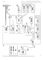
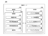
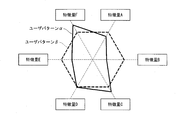
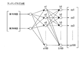
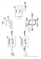
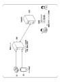
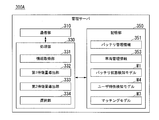
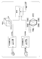
- FIG. 1 It is a figure which shows an example of the management system 1 including the management apparatus of this invention. It is a figure which shows an example of the structure of the vehicle 10. It is a figure which shows an example of the configuration of the management server 300. It is a figure which shows an example of the battery state detection model M1. It is a figure which shows an example of the 3D space model which identifies the state of a battery. It is a figure which shows an example of the user characteristic detection model M2. It is a figure which shows an example of the radar chart which shows the characteristic of a user. It is a figure which shows an example of a matching model M3. This is an example showing an outline of processing by a part of the processing unit 330 of the management server 300.
- FIG. 1 is a diagram showing an example of a management system 1 including the management device of the present invention.
- the management system 1 includes, for example, a vehicle 10, a user terminal 80, a management server 300, and a store terminal 500.
- the vehicle 10, the user terminal 80, the management server 300, and the store terminal 500 are connected via a network NW.
- the network NW includes, for example, the Internet, a WAN (Wide Area Network), a LAN (Local1 Area Network), a provider device, a radio base station, and the like.
- the user terminal 80 is a terminal owned by the user, and includes, for example, a smartphone, a tablet terminal, a personal computer, and the like.
- the management server 300 manages the usage status of the secondary battery mounted on the vehicle 10, for example, based on the information received from the vehicle 10.
- the management server 300 selects a battery suitable for the user based on the usage state of the secondary battery and the like. Details will be described later.
- FIG. 2 is a diagram showing an example of the configuration of the vehicle 10.
- the vehicle 10 includes, for example, a motor 12, a drive wheel 14, a brake device 16, a vehicle sensor 20, a battery device 30, a battery sensor 40, a communication device 50, a charging port 70, a converter 72, and the like. It is equipped with a PCU (Power Control Unit) 100.
- the PCU 100 is an example of a control device.
- the brake device 16 includes, for example, a brake caliper, a cylinder that transmits flood pressure to the brake caliper, and an electric motor that generates flood pressure in the cylinder.
- the brake device 16 may include a mechanism for transmitting the oil pressure generated by the operation of the brake pedal to the cylinder via the master cylinder as a backup.
- the brake device 16 is not limited to the configuration described above, and may be an electronically controlled hydraulic brake device that transmits the flood pressure of the master cylinder to the cylinder.
- the PCU 100 includes, for example, a converter 110, a VCU (Voltage Control Unit) 120, and a control unit 130.
- the converter 110 is, for example, an AC-DC converter.
- the DC side terminal of the converter 110 is connected to the DC link DL.
- the battery device 30 is connected to the DC link DL via the VCU 120.
- the converter 110 converts the alternating current generated by the motor 12 into direct current and outputs it to the direct current link DL.
- the VCU 120 is, for example, a DC-DC converter.
- the VCU 120 boosts the power supplied from the battery device 30 and outputs it to the DC link DL.
- the program may be stored in advance in a storage device (non-transient storage medium) such as an HDD (Hard Disk Drive) or flash memory, or a removable storage medium (non-transient) such as a DVD or CD-ROM. It is stored in a sexual storage medium), and may be installed by attaching the storage medium to a drive device.
- a storage device non-transient storage medium
- HDD Hard Disk Drive
- flash memory or a removable storage medium (non-transient) such as a DVD or CD-ROM. It is stored in a sexual storage medium), and may be installed by attaching the storage medium to a drive device.
- the battery / VCU control unit 135 controls the output of the battery device 30.
- the battery / VCU control unit 135 calculates the SOC (State Of Charge) of the battery 32 based on the output of the battery sensor 40 attached to the battery 32 (described later) of the battery device 30, and outputs the SOC (State Of Charge) to the VCU 120.
- the VCU 120 raises the voltage of the DC link DL in response to an instruction from the battery / VCU control unit 135. Details of the battery device 30 will be described later.
- the battery sensor 40 includes, for example, a current sensor 41, a voltage sensor 43, a temperature sensor 45, and the like.
- the battery sensor 40 detects, for example, the current value, the voltage value, the temperature, and the like for charging and discharging the battery 32.
- the battery sensor 40 outputs the detected current value, voltage value, temperature, etc. to the control unit 130 and the communication device 50.
- the battery sensor 40 may be housed in the housing of the battery device 30 or may be mounted outside the housing.
- the current value, voltage value, temperature, etc. detected by the battery sensor 40 will be referred to as battery parameters.
- the communication device 50 includes a wireless module for connecting a wireless communication network such as a wireless LAN or a cellular network.
- the wireless LAN may be, for example, a method such as Wi-Fi (registered trademark), Bluetooth (registered trademark) or Zigbee (registered trademark).
- the cellular network is, for example, a third-generation mobile communication network (3G), a fourth-generation mobile communication network (Long term evolution: LTE (registered trademark)), a fifth-generation mobile communication network (5G), or the like. Is also good.
- the communication device 50 may acquire the current value, the voltage value, the temperature, and the like output from the battery sensor 40 and transmit them to the outside.
- the storage unit 350 may be, for example, a storage device (non-transient storage medium) such as an HDD (Hard Disk Drive) or a flash memory, or may be a storage device such as an HDD or a flash memory in addition to the storage device. Further, a control circuit may be provided for enabling or disabling the writing of information or the reading of information from the storage device.
- the storage unit 350 stores, for example, battery management information 351 and user management information 352, battery state detection model M1, user characteristic detection model M2, matching model M3, and the like. These pieces of information are written by the processing unit 330 and read by the processing unit 330.
- the program may be stored in advance in a storage device (non-transient storage medium) such as an HDD or flash memory, or in a removable storage medium (non-transient storage medium) such as a DVD or CD-ROM. It is stored and may be installed by attaching the storage medium to the drive device.
- a storage device non-transient storage medium
- non-transient storage medium such as an HDD or flash memory
- a removable storage medium such as a DVD or CD-ROM.
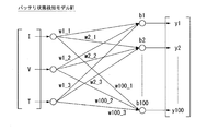
- FIG. 4 is a diagram showing an example of the battery state detection model M1.
- the current value (I), the voltage value (V), and the temperature (T) are input, and the first feature amount (y1, y2, ..., Y100) is input.
- the number of intermediate layers, the weighting coefficient, and the number of first feature quantities shown in FIG. 4 are examples, and are not limited thereto.
- the number of inputs to the model is not limited to this, and may be two or more of the current value, the voltage value, and the temperature. Further, as will be described later, time-series change information of the battery 32, deterioration information of the battery 32, and the like may be input to the model.
- the battery information input to the model is not limited to the current value, the voltage value and the temperature, but is, for example, the SOC (State of Charge) calculated from the current value and the voltage value, and the battery 32 calculated from the current value and the voltage value. It may be the resistance value of.
- the second feature amount deriving unit 333 derives the second feature amount indicating the characteristics of the user based on the information about the user.
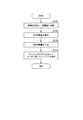
- FIG. 11 is a flowchart showing an example of the processing flow by the processing unit 330.
- the information acquisition unit 331 stores the information received from the vehicle 10 in the storage unit 350 (step S101).
- the first feature amount derivation unit 332 of the battery 32 is based on the result obtained by applying the battery information indicating the current (I), the voltage (V), the temperature (T), etc. to the battery state detection model M1.
- the first feature quantity indicating the state is derived (step S103).
- the second feature amount deriving unit 333 derives the second feature amount indicating the user's characteristics based on the result obtained by applying the user response information to the user characteristic detection model M2 (step S105).
- the selection unit 334 selects the optimum battery based on the result obtained by inputting the first feature amount and the second feature amount into the matching model M3 (step S107).
- the second embodiment is different in that the information acquisition unit 331 acquires vehicle information regarding the running state of the vehicle 10 as information regarding the user.
- the information acquisition unit 331 acquires vehicle information regarding the running state of the vehicle 10 as information regarding the user.
- FIG. 12 is a diagram showing an example of the configuration of the management server 300A.
- the management server 300A differs from the management server 300 in that the vehicle management information 353 is stored in the storage unit 350 instead of the user management information 352, and the user characteristic detection model M4 is stored in the storage unit 350 instead of the user characteristic detection model M2.
- a storage device that stores programs and With a hardware processor, When the hardware processor executes a program stored in the storage device, From the vehicle, the battery information regarding the usage status of the secondary battery mounted on the vehicle and the information regarding the user are acquired, and the information is obtained. Based on the result obtained by applying the battery information to the battery state detection model for identifying the state of the secondary battery, a first feature amount indicating the state of the secondary battery is derived. Based on the information about the user, a second feature amount indicating the characteristics of the user is derived. Based on the result obtained by inputting the first feature amount and the second feature amount into a matching model that outputs a result showing compatibility between the user and the battery based on the first feature amount and the second feature amount. To select a battery suitable for the user, A management device that is configured to.
- Management system 10 ... Vehicle 12 ... Motor 14 ... Drive wheel 16 ... Brake device 20 ... Vehicle sensor 30 ... Battery device 32 ... Battery (storage unit) 40 ... Battery sensor 41 ... Current sensor 43 ... Voltage sensor 45 ... Temperature sensor 50 ... Communication device 70 ... Charging port 72 ... Converter 100 ... PCU 110 ... Converter 120 ... VCU 130 ... Control unit 131 ... Motor control unit 133 ... Brake control unit 135 ... Battery / VCU control unit 300 ... Management server 310 ... Communication unit 331 ... Information acquisition unit 332 ... First feature amount derivation unit 333 ... Second feature amount derivation unit 334 ... Selection unit 330 ... Processing unit 350 ... Storage unit 351 ... Battery management information 352 ... User management information 353 ... Vehicle management information M1 ... Battery status detection model M2 ... User characteristic detection model M3 ... Matching model
Landscapes
- Engineering & Computer Science (AREA)
- Power Engineering (AREA)
- Transportation (AREA)
- Mechanical Engineering (AREA)
- Physics & Mathematics (AREA)
- General Physics & Mathematics (AREA)
- Life Sciences & Earth Sciences (AREA)
- Sustainable Development (AREA)
- Sustainable Energy (AREA)
- Business, Economics & Management (AREA)
- Tourism & Hospitality (AREA)
- Economics (AREA)
- Health & Medical Sciences (AREA)
- General Health & Medical Sciences (AREA)
- Human Resources & Organizations (AREA)
- Marketing (AREA)
- Primary Health Care (AREA)
- Strategic Management (AREA)
- General Business, Economics & Management (AREA)
- Theoretical Computer Science (AREA)
- Secondary Cells (AREA)
- Electric Propulsion And Braking For Vehicles (AREA)
- Management, Administration, Business Operations System, And Electronic Commerce (AREA)
- Charge And Discharge Circuits For Batteries Or The Like (AREA)
Abstract
Description
(1):この発明の一態様に係る管理装置は、車両から、前記車両に搭載されている二次電池の使用状態に関するバッテリ情報と、ユーザに関する情報とを取得する情報取得部と、前記バッテリ情報を、前記二次電池の状態を識別するバッテリ状態検知モデルに適用することで得られた結果に基づいて、前記二次電池の状態を示す第1特徴量を導出する第1特徴量導出部と、前記ユーザに関する情報に基づいて、前記ユーザの特性を示す第2特徴量を導出する第2特徴量導出部と、前記第1特徴量と前記第2特徴量に基づいてユーザとバッテリの相性を示す結果を出力するマッチングモデルに、前記第1特徴量と前記第2特徴量を入力することで得られる結果に基づいて、前記ユーザに適したバッテリを選択する選択部と、を備えるものである。
以下、図面を参照し、本発明の管理装置、管理方法、およびプログラムの実施形態について説明する。図1は、本発明の管理装置を含む管理システム1の一例を示す図である。図1に示すように、管理システム1は、例えば、車両10と、ユーザ端末80と、管理サーバ300と、店舗端末500とを含む。車両10と、ユーザ端末80と、管理サーバ300と、店舗端末500とは、ネットワークNWを介して接続されている。なお、ネットワークNWは、例えば、インターネット、WAN(Wide Area Network)、LAN(Local1 Area Network)、プロバイダ装置、無線基地局などを含む。
図2は、車両10の構成の一例を示す図である。車両10には、例えば、モータ12と、駆動輪14と、ブレーキ装置16と、車両センサ20と、バッテリ装置30と、バッテリセンサ40と、通信装置50と、充電口70と、コンバータ72と、PCU(Power Control Unit)100とを備える。PCU100は、制御装置の一例である。
図3は、管理サーバ300の構成の一例を示す図である。管理サーバ300は、例えば、通信部310と、処理部330と、記憶部350とを含む。通信部310は、例えば、無線LANやセルラ網等の無線通信ネットワークを接続するための無線モジュールを含む。無線LANは、例えばWi-Fi(登録商標)、Bluetooth(登録商標)やZigbee(登録商標)といった方式でも良い。セルラ網は、例えば第三世代移動体通信網(3G)、第四世代移動大通信網(Long term evolution:LTE(登録商標))、または第五世代移動体通信網(5G)等であっても良い。
以上説明したように、本実施形態の管理サーバ300は、車両10から、車両10に搭載されている二次電池の使用状態に関するバッテリ情報と、ユーザに関する情報とを取得する情報取得部331と、バッテリ情報を二次電池の状態を識別するバッテリ状態検知モデルに適用することで得られた結果に基づいて、二次電池の状態を示す第1特徴量を導出する第1特徴量導出部332と、ユーザに関する情報に基づいて、ユーザの特性を示す第2特徴量を導出する第2特徴量導出部333と、第1特徴量と第2特徴量に基づいてユーザとバッテリの相性を示す結果を出力するマッチングモデルに、第1特徴量と第2特徴量を入力することで得られる結果に基づいて、ユーザに適したバッテリを選択する選択部334と、を備えることにより、ユーザに適したバッテリを提案することができる。
次に、第2実施形態について説明する。第2実施形態では、情報取得部331が、ユーザに関する情報として、車両10の走行状態に関する車両情報を取得する点が異なる。以下、第1実施形態と異なる点について説明し、同様の点については説明を省略する。
プログラムを記憶した記憶装置と、
ハードウェアプロセッサと、を備え、
前記ハードウェアプロセッサが前記記憶装置に記憶されたプログラムを実行することにより、
車両から、前記車両に搭載されている二次電池の使用状態に関するバッテリ情報と、ユーザに関する情報とを取得し、
前記バッテリ情報を、前記二次電池の状態を識別するバッテリ状態検知モデルに適用することで得られた結果に基づいて、前記二次電池の状態を示す第1特徴量を導出し、
前記ユーザに関する情報に基づいて、前記ユーザの特性を示す第2特徴量を導出し、
前記第1特徴量と前記第2特徴量に基づいてユーザとバッテリの相性を示す結果を出力するマッチングモデルに、前記第1特徴量と前記第2特徴量を入力することで得られる結果に基づいて、前記ユーザに適したバッテリを選択する、
ように構成されている、管理装置。
10…車両
12…モータ
14…駆動輪
16…ブレーキ装置
20…車両センサ
30…バッテリ装置
32…バッテリ(蓄電部)
40…バッテリセンサ
41…電流センサ
43…電圧センサ
45…温度センサ
50…通信装置
70…充電口
72…コンバータ
100…PCU
110…変換器
120…VCU
130…制御部
131…モータ制御部
133…ブレーキ制御部
135…バッテリ・VCU制御部
300…管理サーバ
310…通信部
331…情報取得部
332…第1特徴量導出部
333…第2特徴量導出部
334…選択部
330…処理部
350…記憶部
351…バッテリ管理情報
352…ユーザ管理情報
353…車両管理情報
M1…バッテリ状態検知モデル
M2…ユーザ特性検知モデル
M3…マッチングモデル
Claims (6)
- 車両から、前記車両に搭載されている二次電池の使用状態に関するバッテリ情報と、ユーザに関する情報とを取得する情報取得部と、
前記バッテリ情報を、前記二次電池の状態を識別するバッテリ状態検知モデルに適用することで得られた結果に基づいて、前記二次電池の状態を示す第1特徴量を導出する第1特徴量導出部と、
前記ユーザに関する情報に基づいて、前記ユーザの特性を示す第2特徴量を導出する第2特徴量導出部と、
前記第1特徴量と前記第2特徴量に基づいてユーザとバッテリの相性を示す結果を出力するマッチングモデルに、前記第1特徴量と前記第2特徴量を入力することで得られる結果に基づいて、前記ユーザに適したバッテリを選択する選択部と、
を備える管理装置。 - 前記情報取得部は、
前記ユーザに関する情報として、前記車両の走行状態に関する車両情報を取得し、
前記第2特徴量導出部は、
前記車両情報を、前記ユーザの特性を識別するユーザ特性検知モデルに適用することで得られた結果に基づいて、前記第2特徴量を導出する、
請求項1に記載の管理装置。 - 前記情報取得部は、
前記バッテリ情報として前記二次電池の使用状態を示す検出値を取得し、
前記第1特徴量導出部は、
前記バッテリ情報を前記バッテリ状態検知モデルに適用することで得られた結果を、前記二次電池の容量、前記二次電池のSOC-OCV曲線、および前記二次電池の内部抵抗で定義される三次元空間モデルで表すことで前記バッテリの状態を識別する特徴量を、前記第1特徴量として導出する、
請求項1または2に記載の管理装置。 - 前記情報取得部は、
前記検出値として、前記二次電池を充放電した時の電流、電圧、および温度を示す情報を取得する、
請求項3に記載の管理装置。 - コンピュータが、
車両から、前記車両に搭載されている二次電池の使用状態に関するバッテリ情報と、ユーザに関する情報とを取得し、
前記バッテリ情報を、前記二次電池の状態を識別するバッテリ状態検知モデルに適用することで得られた結果に基づいて、前記二次電池の状態を示す第1特徴量を導出し、
前記ユーザに関する情報に基づいて、前記ユーザの特性を示す第2特徴量を導出し、
前記第1特徴量と前記第2特徴量に基づいてユーザとバッテリの相性を示す結果を出力するマッチングモデルに、前記第1特徴量と前記第2特徴量を入力することで得られる結果に基づいて、前記ユーザに適したバッテリを選択する、
管理方法。 - コンピュータに、
車両から、前記車両に搭載されている二次電池の使用状態に関するバッテリ情報と、ユーザに関する情報とを取得させ、
前記バッテリ情報を、前記二次電池の状態を識別するバッテリ状態検知モデルに適用することで得られた結果に基づいて、前記二次電池の状態を示す第1特徴量を導出させ、
前記ユーザに関する情報に基づいて、前記ユーザの特性を示す第2特徴量を導出させ、
前記第1特徴量と前記第2特徴量に基づいてユーザとバッテリの相性を示す結果を出力するマッチングモデルに、前記第1特徴量と前記第2特徴量を入力することで得られる結果に基づいて、前記ユーザに適したバッテリを選択させる、
プログラム。
Priority Applications (4)
| Application Number | Priority Date | Filing Date | Title |
|---|---|---|---|
| JP2021528050A JP7232330B2 (ja) | 2019-06-17 | 2019-06-17 | 管理装置、管理方法、及びプログラム |
| US17/611,593 US11794606B2 (en) | 2019-06-17 | 2019-06-17 | Management device, management method, and program |
| PCT/JP2019/023874 WO2020255196A1 (ja) | 2019-06-17 | 2019-06-17 | 管理装置、管理方法、及びプログラム |
| CN201980096611.1A CN113874903B (zh) | 2019-06-17 | 2019-06-17 | 管理装置、管理方法及存储介质 |
Applications Claiming Priority (1)
| Application Number | Priority Date | Filing Date | Title |
|---|---|---|---|
| PCT/JP2019/023874 WO2020255196A1 (ja) | 2019-06-17 | 2019-06-17 | 管理装置、管理方法、及びプログラム |
Publications (1)
| Publication Number | Publication Date |
|---|---|
| WO2020255196A1 true WO2020255196A1 (ja) | 2020-12-24 |
Family
ID=74040170
Family Applications (1)
| Application Number | Title | Priority Date | Filing Date |
|---|---|---|---|
| PCT/JP2019/023874 Ceased WO2020255196A1 (ja) | 2019-06-17 | 2019-06-17 | 管理装置、管理方法、及びプログラム |
Country Status (4)
| Country | Link |
|---|---|
| US (1) | US11794606B2 (ja) |
| JP (1) | JP7232330B2 (ja) |
| CN (1) | CN113874903B (ja) |
| WO (1) | WO2020255196A1 (ja) |
Families Citing this family (1)
| Publication number | Priority date | Publication date | Assignee | Title |
|---|---|---|---|---|
| JP7058254B2 (ja) * | 2019-10-11 | 2022-04-21 | 京セラ株式会社 | 情報処理装置、情報処理方法、及びプログラム |
Citations (3)
| Publication number | Priority date | Publication date | Assignee | Title |
|---|---|---|---|---|
| JP2013084198A (ja) * | 2011-10-12 | 2013-05-09 | Nissan Motor Co Ltd | バッテリ検索装置およびバッテリ検索方法 |
| JP2016008873A (ja) * | 2014-06-24 | 2016-01-18 | トヨタ自動車株式会社 | 電池管理システム |
| WO2018104965A1 (en) * | 2016-12-07 | 2018-06-14 | Kumar Maini Chetan | Battery swapping systems and methods |
Family Cites Families (8)
| Publication number | Priority date | Publication date | Assignee | Title |
|---|---|---|---|---|
| US8046180B2 (en) * | 2007-07-13 | 2011-10-25 | Honeywell International Inc. | Model-based determination of power source replacement in wireless and other devices |
| US9263901B2 (en) | 2012-05-19 | 2016-02-16 | Tesla Motors, Inc. | Secondary service port for high voltage battery packs |
| US8791809B2 (en) * | 2012-12-28 | 2014-07-29 | International Business Machines Corporation | Optimal electric vehicle battery recommendation system |
| JP6033155B2 (ja) * | 2013-03-29 | 2016-11-30 | 日立オートモティブシステムズ株式会社 | 電池制御装置 |
| WO2016158396A1 (ja) * | 2015-03-31 | 2016-10-06 | 日立オートモティブシステムズ株式会社 | 電池制御装置、および電動車両システム |
| US10114079B2 (en) * | 2016-02-24 | 2018-10-30 | Ford Global Technologies, Llc | System and method for identifying vehicle battery decay |
| JP6683144B2 (ja) * | 2017-02-07 | 2020-04-15 | トヨタ自動車株式会社 | 電池交換支援システムおよびそれに用いられるサーバ |
| US11691518B2 (en) * | 2017-07-21 | 2023-07-04 | Quantumscape Battery, Inc. | Predictive model for estimating battery states |
-
2019
- 2019-06-17 JP JP2021528050A patent/JP7232330B2/ja active Active
- 2019-06-17 CN CN201980096611.1A patent/CN113874903B/zh active Active
- 2019-06-17 WO PCT/JP2019/023874 patent/WO2020255196A1/ja not_active Ceased
- 2019-06-17 US US17/611,593 patent/US11794606B2/en active Active
Patent Citations (3)
| Publication number | Priority date | Publication date | Assignee | Title |
|---|---|---|---|---|
| JP2013084198A (ja) * | 2011-10-12 | 2013-05-09 | Nissan Motor Co Ltd | バッテリ検索装置およびバッテリ検索方法 |
| JP2016008873A (ja) * | 2014-06-24 | 2016-01-18 | トヨタ自動車株式会社 | 電池管理システム |
| WO2018104965A1 (en) * | 2016-12-07 | 2018-06-14 | Kumar Maini Chetan | Battery swapping systems and methods |
Also Published As
| Publication number | Publication date |
|---|---|
| JP7232330B2 (ja) | 2023-03-02 |
| CN113874903B (zh) | 2025-06-03 |
| CN113874903A (zh) | 2021-12-31 |
| US20220144130A1 (en) | 2022-05-12 |
| JPWO2020255196A1 (ja) | 2020-12-24 |
| US11794606B2 (en) | 2023-10-24 |
Similar Documents
| Publication | Publication Date | Title |
|---|---|---|
| US12220993B2 (en) | Vehicle, server device, display control method, and program | |
| JP7075919B2 (ja) | バッテリ情報提供装置、バッテリ情報提供システム、バッテリ情報提供方法、およびプログラム | |
| JP6911747B2 (ja) | 電池情報処理装置、電池製造支援装置、組電池、電池情報処理方法、及び組電池の製造方法 | |
| CN112534671B (zh) | 提示装置、提示方法以及存储介质 | |
| JP7048519B2 (ja) | 二次電池状態検知システム、二次電池状態検知装置および二次電池状態検知方法 | |
| JP6942775B2 (ja) | バッテリ状態判定システム、およびバッテリ状態判定方法 | |
| JP7232330B2 (ja) | 管理装置、管理方法、及びプログラム | |
| JP6827989B2 (ja) | 提示装置、提示方法、及びプログラム | |
| JP7408609B2 (ja) | 制御装置、およびプログラム | |
| CN113682188B (zh) | 控制装置、控制系统、控制方法及存储介质 | |
| JP7149226B2 (ja) | 電動車両の製造管理装置、製造方法、製造管理方法、及びプログラム | |
| US20200274206A1 (en) | Battery device | |
| US20230314526A1 (en) | Availability determination apparatus, availability determination method, and program | |
| JP7403563B2 (ja) | バッテリ情報管理方法およびプログラム | |
| JP7090750B2 (ja) | バッテリ特定システムおよびバッテリ特定方法 | |
| JP2021047665A (ja) | 評価額保証装置、評価額保証方法、およびプログラム | |
| CN119705409B (zh) | 一种能量管理方法、能量管理系统、终端设备及存储介质 | |
| US20200395777A1 (en) | Control apparatus, control method, and program | |
| CN121200868A (zh) | 车辆能量回收方法、系统、设备及存储介质 |
Legal Events
| Date | Code | Title | Description |
|---|---|---|---|
| 121 | Ep: the epo has been informed by wipo that ep was designated in this application |
Ref document number: 19933408 Country of ref document: EP Kind code of ref document: A1 |
|
| ENP | Entry into the national phase |
Ref document number: 2021528050 Country of ref document: JP Kind code of ref document: A |
|
| NENP | Non-entry into the national phase |
Ref country code: DE |
|
| 122 | Ep: pct application non-entry in european phase |
Ref document number: 19933408 Country of ref document: EP Kind code of ref document: A1 |
|
| WWG | Wipo information: grant in national office |
Ref document number: 201980096611.1 Country of ref document: CN |