WO2020250601A1 - 処理装置、処理方法及びプログラム - Google Patents
処理装置、処理方法及びプログラム Download PDFInfo
- Publication number
- WO2020250601A1 WO2020250601A1 PCT/JP2020/018505 JP2020018505W WO2020250601A1 WO 2020250601 A1 WO2020250601 A1 WO 2020250601A1 JP 2020018505 W JP2020018505 W JP 2020018505W WO 2020250601 A1 WO2020250601 A1 WO 2020250601A1
- Authority
- WO
- WIPO (PCT)
- Prior art keywords
- vehicle
- orientation
- detection unit
- unit
- power supply
- Prior art date
- Legal status (The legal status is an assumption and is not a legal conclusion. Google has not performed a legal analysis and makes no representation as to the accuracy of the status listed.)
- Ceased
Links
Images

Classifications
-
- G—PHYSICS
- G01—MEASURING; TESTING
- G01C—MEASURING DISTANCES, LEVELS OR BEARINGS; SURVEYING; NAVIGATION; GYROSCOPIC INSTRUMENTS; PHOTOGRAMMETRY OR VIDEOGRAMMETRY
- G01C21/00—Navigation; Navigational instruments not provided for in groups G01C1/00 - G01C19/00
- G01C21/26—Navigation; Navigational instruments not provided for in groups G01C1/00 - G01C19/00 specially adapted for navigation in a road network
- G01C21/34—Route searching; Route guidance
- G01C21/36—Input/output arrangements for on-board computers
- G01C21/3667—Display of a road map
- G01C21/367—Details, e.g. road map scale, orientation, zooming, illumination, level of detail, scrolling of road map or positioning of current position marker
-
- G—PHYSICS
- G01—MEASURING; TESTING
- G01C—MEASURING DISTANCES, LEVELS OR BEARINGS; SURVEYING; NAVIGATION; GYROSCOPIC INSTRUMENTS; PHOTOGRAMMETRY OR VIDEOGRAMMETRY
- G01C25/00—Manufacturing, calibrating, cleaning, or repairing instruments or devices referred to in the other groups of this subclass
- G01C25/005—Manufacturing, calibrating, cleaning, or repairing instruments or devices referred to in the other groups of this subclass initial alignment, calibration or starting-up of inertial devices
-
- G—PHYSICS
- G01—MEASURING; TESTING
- G01C—MEASURING DISTANCES, LEVELS OR BEARINGS; SURVEYING; NAVIGATION; GYROSCOPIC INSTRUMENTS; PHOTOGRAMMETRY OR VIDEOGRAMMETRY
- G01C21/00—Navigation; Navigational instruments not provided for in groups G01C1/00 - G01C19/00
- G01C21/20—Instruments for performing navigational calculations
-
- G—PHYSICS
- G01—MEASURING; TESTING
- G01C—MEASURING DISTANCES, LEVELS OR BEARINGS; SURVEYING; NAVIGATION; GYROSCOPIC INSTRUMENTS; PHOTOGRAMMETRY OR VIDEOGRAMMETRY
- G01C21/00—Navigation; Navigational instruments not provided for in groups G01C1/00 - G01C19/00
- G01C21/26—Navigation; Navigational instruments not provided for in groups G01C1/00 - G01C19/00 specially adapted for navigation in a road network
- G01C21/34—Route searching; Route guidance
- G01C21/36—Input/output arrangements for on-board computers
- G01C21/3626—Details of the output of route guidance instructions
- G01C21/3647—Guidance involving output of stored or live camera images or video streams
-
- G—PHYSICS
- G06—COMPUTING OR CALCULATING; COUNTING
- G06V—IMAGE OR VIDEO RECOGNITION OR UNDERSTANDING
- G06V20/00—Scenes; Scene-specific elements
- G06V20/50—Context or environment of the image
- G06V20/56—Context or environment of the image exterior to a vehicle by using sensors mounted on the vehicle
-
- G—PHYSICS
- G06—COMPUTING OR CALCULATING; COUNTING
- G06V—IMAGE OR VIDEO RECOGNITION OR UNDERSTANDING
- G06V20/00—Scenes; Scene-specific elements
- G06V20/50—Context or environment of the image
- G06V20/56—Context or environment of the image exterior to a vehicle by using sensors mounted on the vehicle
- G06V20/58—Recognition of moving objects or obstacles, e.g. vehicles or pedestrians; Recognition of traffic objects, e.g. traffic signs, traffic lights or roads
- G06V20/584—Recognition of moving objects or obstacles, e.g. vehicles or pedestrians; Recognition of traffic objects, e.g. traffic signs, traffic lights or roads of vehicle lights or traffic lights
-
- G—PHYSICS
- G06—COMPUTING OR CALCULATING; COUNTING
- G06V—IMAGE OR VIDEO RECOGNITION OR UNDERSTANDING
- G06V20/00—Scenes; Scene-specific elements
- G06V20/50—Context or environment of the image
- G06V20/59—Context or environment of the image inside of a vehicle, e.g. relating to seat occupancy, driver state or inner lighting conditions
-
- G—PHYSICS
- G09—EDUCATION; CRYPTOGRAPHY; DISPLAY; ADVERTISING; SEALS
- G09B—EDUCATIONAL OR DEMONSTRATION APPLIANCES; APPLIANCES FOR TEACHING, OR COMMUNICATING WITH, THE BLIND, DEAF OR MUTE; MODELS; PLANETARIA; GLOBES; MAPS; DIAGRAMS
- G09B29/00—Maps; Plans; Charts; Diagrams, e.g. route diagram
-
- G—PHYSICS
- G09—EDUCATION; CRYPTOGRAPHY; DISPLAY; ADVERTISING; SEALS
- G09B—EDUCATIONAL OR DEMONSTRATION APPLIANCES; APPLIANCES FOR TEACHING, OR COMMUNICATING WITH, THE BLIND, DEAF OR MUTE; MODELS; PLANETARIA; GLOBES; MAPS; DIAGRAMS
- G09B29/00—Maps; Plans; Charts; Diagrams, e.g. route diagram
- G09B29/10—Map spot or coordinate position indicators; Map reading aids
Definitions
- the present invention relates to a processing device, a processing method and a program.
- the navigation system which is an example of the processing device mounted on the vehicle, is required to improve the accuracy of the orientation of the vehicle (that is, the orientation of the vehicle in the traveling direction) displayed on the map.
- the orientation of the vehicle parked in the multi-storey car park changes due to the rotation of the turntable, or if the orientation of the vehicle changes during the period when the ACC power supply (accessory power supply) is turned off, the accessory power supply It is necessary to correct the direction of the vehicle displayed on the map immediately after the is switched from OFF to ON.
- the in-vehicle processing device of Patent Document 1 inputs direction correction information for correcting the direction of the vehicle together with arbitrary position information of the vehicle on the map, and when the vehicle is arranged on the position information, the direction correction It is configured to correct the direction of the vehicle on the map based on the information.
- the direction correction information for correcting the direction of the vehicle together with arbitrary position information of the vehicle on the map, and when the vehicle is arranged on the position information, the direction correction It is configured to correct the direction of the vehicle on the map based on the information.
- An object of the present invention has been made to solve the above-mentioned problems, and to realize a processing device, a processing method, and a program capable of easily correcting the orientation of a vehicle displayed on a map of a navigation system.
- the processing apparatus is A vibration detector that detects the vibration of the vehicle and An orientation detection unit that detects the orientation of the vehicle, A storage unit that stores information indicating the direction of the vehicle, A processing unit that sets the direction of the vehicle on the map of the navigation system based on the information indicating the direction of the vehicle.
- a power supply control unit that controls the supply of power to the orientation detection unit and the storage unit based on the detection result of the vibration detection unit. To be equipped.
- the processing method is When the accessory power supply of the vehicle is turned off, the step of continuing to supply power to the vibration detection unit that detects the vibration of the vehicle, and When the vibration detection unit detects vibration equal to or higher than a preset first threshold value while the accessory power supply of the vehicle is turned off, the orientation detection unit for detecting the orientation of the vehicle and the orientation of the vehicle are detected.
- a step of supplying power to a storage unit that stores the indicated information the orientation detection unit detects the orientation of the vehicle, and the storage unit stores the detected information indicating the orientation of the vehicle.
- the program according to this embodiment is When the accessory power supply of the vehicle is turned off, the step of continuing to supply power to the vibration detection unit that detects the vibration of the vehicle, and When the vibration detection unit detects vibration equal to or higher than a preset first threshold value while the accessory power supply of the vehicle is turned off, the orientation detection unit for detecting the orientation of the vehicle and the orientation of the vehicle are detected.
- a step of supplying power to a storage unit that stores the indicated information the orientation detection unit detects the orientation of the vehicle, and the storage unit stores the detected information indicating the orientation of the vehicle.
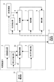
- FIG. It is a block diagram which shows the structure of the processing apparatus of Embodiment 1.
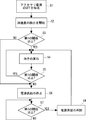
- FIG. It is a figure which shows the flow of operation of the processing apparatus of Embodiment 1.
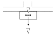
- FIG. It is a figure which shows the navigation image when the accessory power supply was switched from OFF to ON in order to leave a multi-storey car park by a vehicle equipped with a navigation system which does not have a vehicle orientation correction function.
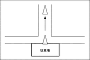
- FIG. It is a figure which shows the navigation image at the time of switching the accessory power supply from OFF to ON in order to leave a vehicle equipped with the processing apparatus of Embodiment 1 from a multi-storey car park.
- It is a block diagram which shows the structure of the processing apparatus of Embodiment 2.
- FIG. 1 is a block diagram showing a configuration of a processing device according to the present embodiment.
- the processing device 1 is suitable as, for example, a navigation system mounted on a vehicle.
- the processing device 1 includes a vibration detection unit 2, an ON / OFF detection unit 3, a power supply control unit 4, a direction detection unit 5, a GPS (Global Positioning System) reception unit 6, a storage unit 7, and a processing unit. 8 and a display unit 9 are provided.
- the vibration detection unit 2, the ON / OFF detection unit 3, and the power supply control unit 4 are operated by the power supply supplied from the first power supply unit 10, and the orientation detection unit 5, the GPS reception unit 6, the storage unit 7, and the processing unit 8 operate.
- the display unit 9 is operated by the power supply supplied from the second power supply unit 11.
- the first power supply unit 10 and the second power supply unit 11 can be configured by a battery mounted on the vehicle, and the first power supply unit 10 may be a backup power supply unit.
- the vibration detection unit 2 detects the vibration of the vehicle.
- the vibration detection unit 2 includes, for example, an acceleration sensor, detects the acceleration generated in the vehicle, and outputs information indicating the detected acceleration in the vehicle to the power supply control unit 4.
- the vibration detection unit 2 may be provided with a displacement sensor or the like as long as it can detect the vibration of the vehicle.
- the ON / OFF detection unit 3 detects ON / OFF switching of the accessory power supply of the vehicle.
- the ON / OFF detection unit 3 outputs information indicating the detected ON / OFF switching result of the accessory power supply of the vehicle to the power supply control unit 4.
- the power supply control unit 4 controls the second power supply unit 11 and controls the supply of power to the orientation detection unit 5, the GPS reception unit 6, the storage unit 7, the processing unit 8, and the display unit 9. To do. Further, the power supply control unit 4 calculates the vibration value of the vehicle based on the acceleration generated in the vehicle indicated by the information input from the vibration detection unit 2.
- the power supply control unit 4 controls the second power supply unit 11 so that the processing device 1 functions as a navigation system when the accessory power supply of the vehicle is ON, and the orientation detection unit 5 and the GPS reception unit 6 Power is supplied to the storage unit 7, the processing unit 8, and the display unit 9.
- the power supply control unit 4 controls the second power supply unit 11 and stops the supply of power to the GPS receiving unit 6 and the display unit 9, although the details will be described later.
- the second power supply unit 11 is controlled based on the calculated vibration value of the vehicle, and the supply of power to the orientation detection unit 5, the storage unit 7, and the processing unit 8 is controlled.
- the orientation detection unit 5 detects the orientation of the vehicle.
- the orientation detection unit 5 includes, for example, a gyro sensor, detects the rotational angular velocity of the vehicle around an axis extending in the vertical direction of the vehicle, and outputs information indicating the detected rotational angular velocity of the vehicle to the processing unit 8. To do.
- the orientation detection unit 5 may be provided with a generally used inertial sensor capable of detecting the rotational angular velocity.
- the GPS receiving unit 6 receives vehicle position information from GPS satellites and outputs the received position information to the processing unit 8.
- the processing device 1 of the present embodiment includes the GPS receiving unit 6, it can receive vehicle position information from other satellite positioning systems such as GLONASS (Global Navigation Satellite System) and the quasi-zenith satellite system Michibiki. It may be a position information receiving unit, and in short, it may be a configuration that can acquire the position information of the vehicle from the outside.
- a map DB Data-Base
- the storage unit 7 stores information indicating the direction of the vehicle calculated by the processing unit 8 as described later.
- the processing unit 8 calculates the direction of the vehicle based on the rotational angular velocity of the vehicle indicated by the information input from the direction detection unit 5, and outputs the calculated information indicating the direction of the vehicle to the storage unit 7.
- the processing unit 8 will be described in detail later, but the map DB read from the storage unit 7, the direction of the vehicle indicated by the information read from the storage unit 7, and the position of the vehicle indicated by the information input from the GPS receiving unit 6. Map matching is performed based on the above, and a navigation image displayed on the display unit 9 is generated.
- the display unit 9 displays a navigation image.
- the display unit 9 includes a liquid crystal display panel, a touch panel laminated on the liquid crystal display panel, and the like. The user can realize various operations of the navigation system by touching the display unit 9.
- the display unit 9 may be provided with an organic EL (Electro-Luminescence) panel or the like, and may at least have a configuration capable of displaying a navigation image.
- organic EL Electro-Luminescence
- FIG. 2 is a diagram showing an operation flow of the processing apparatus of the present embodiment.
- the operation of the processing device 1 after entering the multi-storey car park where the direction of the vehicle changes and the accessory power supply is turned off will be described.
- the ON / OFF detection unit 3 detects that the accessory power supply has been turned off and outputs information indicating the detection result to the power supply control unit 4 (S1). ). At this time, the vibration detection unit 2, the ON / OFF detection unit 3, and the power supply control unit 4 continue to supply power from the first power supply unit 10.
- the vibration detection unit 2 continues to detect the vibration of the vehicle, and the ON / OFF detection unit 3 continues to detect the ON / OFF switching of the accessory power supply.
- the power supply control unit 4 controls the second power supply unit 11 based on the detection result indicated by the information input from the ON / OFF detection unit 3, and supplies power to the GPS receiving unit 6 and the display unit 9. To stop. On the other hand, the power supply control unit 4 controls the second power supply unit 11 and continues to supply power to the orientation detection unit 5, the storage unit 7, and the processing unit 8.
- the vibration detection unit 2 starts detecting the acceleration generated in the vehicle, and outputs information indicating the detected acceleration in the vehicle to the power supply control unit 4 (S2).
- the power supply control unit 4 calculates the vibration value of the vehicle based on the acceleration generated in the vehicle indicated by the information input from the vibration detection unit 2, and within the preset first period, the preset first period. It is determined whether or not a vibration value equal to or greater than the threshold value of 1 has been calculated (S3).
- the first period can be appropriately set according to, for example, the period from when the vehicle is placed on the turntable of the multi-storey car park until the turntable starts to rotate. It only takes about a minute.
- the first threshold value can be set to, for example, a vibration value transmitted to the vehicle when the turntable rotates. However, these first period and the first threshold value can be set as appropriate.
- the power supply control unit 4 controls the second power supply unit 11 when the vibration value equal to or higher than the first threshold value is calculated within the first period after the accessory power supply of the vehicle is turned off (YES in S3). , The power supply to the orientation detection unit 5, the storage unit 7, and the processing unit 8 is continued.
- the processing unit 8 calculates the direction of the vehicle (S4). Specifically, the orientation detection unit 5 outputs information indicating the detected rotational angular velocity of the vehicle to the processing unit 8. The processing unit 8 calculates the current vehicle orientation based on the vehicle rotation angular velocity indicated by the information input from the orientation detection unit 5, and outputs the calculated information indicating the current vehicle orientation to the storage unit 7. ..
- the power supply control unit 4 determines whether or not the calculated vibration value of the vehicle is calculated again within the first period after the calculated vibration value of the vehicle is less than the first threshold value. (S5), when the vibration value equal to or higher than the first threshold value is calculated (YES in S5), the power supply to the orientation detection unit 5, the storage unit 7, and the processing unit 8 is continued, and the step S4 is executed. ..
- the power supply control unit 4 does not calculate the vibration value equal to or higher than the first threshold value again within the first period after the calculated vibration value of the vehicle becomes less than the first threshold value (S5). NO), the second power supply unit 11 is controlled, and the supply of power to the orientation detection unit 5, the storage unit 7, and the processing unit 8 is stopped (S6).
- the power supply control unit 4 calculates the vibration value of the vehicle based on the acceleration generated in the vehicle indicated by the information input from the vibration detection unit 2.
- the determination of whether or not the vehicle is equal to or higher than the first threshold value is continued (S7), and when the calculated vibration value of the vehicle is equal to or higher than the first threshold value (YES in S7), the second power supply unit 11 is controlled to detect the orientation.
- the supply of power to the unit 5, the storage unit 7, and the processing unit 8 is restarted (S8), and the process returns to the process of S4.
- the power supply control unit 4 controls the second power supply unit 11, and the orientation detection unit 5, the storage unit 7, and the processing unit 8 Continue to stop the supply of power to S7 and return to the process of S7. Further, when the power supply control unit 4 does not calculate the vibration value equal to or higher than the first threshold value within the first period after the accessory power supply of the vehicle is turned off (NO in S3), the power supply control unit 4 executes the step S6. To do.
- the ON / OFF detection unit 3 detects that the accessory power is turned on and shows the detection result.
- the information is output to the power supply control unit 4.
- the power supply control unit 4 controls the second power supply unit 11 and supplies power to the orientation detection unit 5, the GPS reception unit 6, the storage unit 7, the processing unit 8, and the display unit 9.
- the processing unit 8 reads out the map DB and the latest vehicle orientation information from the storage unit 7, and is based on the map DB, the latest vehicle orientation, and the vehicle position indicated by the information input from the GPS receiving unit 6. , Map matching is performed, a navigation image is generated, and the display unit 9 is displayed.
- FIG. 3 is a diagram showing a navigation image when a vehicle equipped with a navigation system not provided with a vehicle orientation correction function switches the accessory power supply from OFF to ON in order to leave the multi-storey car park.
- FIG. 4 is a diagram showing a navigation image when a vehicle equipped with the processing device of the present embodiment switches the accessory power supply from OFF to ON in order to leave the multi-storey car park.
- ⁇ indicates a vehicle.
- the orientation of the vehicle on the map of the navigation image is the orientation when the vehicle enters the multi-storey car park, as shown in FIG. Until then, if the direction of the vehicle changes in the multi-storey car park, it is not possible to quickly correct the direction of the vehicle.
- the processing device 1 of the present embodiment even if the accessory power supply is turned off, the latest vehicle orientation is acquired as described above, so that even if the vehicle orientation changes in the multi-storey car park. , As shown in FIG. 4, the orientation of the vehicle on the map of the navigation image can be quickly corrected.
- the processing device 1 itself automatically corrects the direction of the vehicle on the map, so that the user corrects the direction of the vehicle on the map. You can easily correct the orientation of the vehicle on the map without having to enter any information.
- the orientation detection unit 5 Since the supply of power to the storage unit 7 and the processing unit 8 is cut off, the power consumption of the second power supply unit 11 can be suppressed.
- map matching is performed using the position information of the vehicle received by the GPS receiving unit 6, so that, for example, the vehicle is transported by a loaded vehicle or the like and the orientation or position of the vehicle is used.
- map matching can be performed quickly even if it differs before and after transportation.
- the power supply to the orientation detection unit 5, the storage unit 7, and the processing unit 8 is supplied. Since the supply is continued, for example, after the vehicle enters the multi-storey car park, the orientation detection unit 5, the storage unit 7, and the processing unit 8 can be operated satisfactorily until the turntable starts to rotate.
- FIG. 5 is a block diagram showing a configuration of the processing device of the present embodiment.
- the description overlapping with the first embodiment will be omitted, and the same elements will be described using the same reference numerals.
- the processing device 21 of the present embodiment has substantially the same configuration as the processing device 1 of the first embodiment, but when the orientation of the vehicle on the map of the navigation image is corrected, the user is alerted. A warning unit 22 for this purpose is provided.
- the alert unit 22 is provided with, for example, a speaker, etc., and power is supplied from the second power supply unit 11. Then, the alerting unit 22 is controlled by the processing unit 23. Specifically, when the accessory power supply of the vehicle is switched from OFF to ON, the processing unit 23 provides information indicating the direction of the vehicle immediately before the accessory power supply is switched from ON to OFF from the storage unit 7, and the accessory power supply is changed from OFF. When the information indicating the direction of the vehicle immediately after switching to ON is read and the directions of the vehicles indicated by the mutual information are different, the alerting unit 22 is controlled, for example, "Note that the direction of the vehicle has been corrected. Output a voice such as "Please".
- the vehicle user can correct the orientation of the vehicle on the map of the navigation image when, for example, the orientation of the vehicle changes between when entering the multi-storey car park and when leaving the multi-storey car park. You can recognize that you are.
- the user is alerted by voice, but the display unit 9 may display the alert information.
- the alerting unit 22 may be any means that can alert the user when the orientation of the vehicle is corrected on the map of the navigation image.
- ⁇ Embodiment 3 Facilities where the direction of vehicles changes, such as multi-storey car parks, are generally dark and closed spaces. Therefore, the processing device of the present embodiment is configured to operate the above-mentioned function of correcting the orientation of the vehicle only when the brightness inside the vehicle or the periphery of the vehicle is dark.
- FIG. 6 is a block diagram showing the configuration of the processing device of the present embodiment.
- the description overlapping with the first embodiment and the like will be omitted, and the same elements will be described using the same reference numerals.
- the processing device 31 of the present embodiment has substantially the same configuration as the processing device 1 of the first embodiment, but includes a brightness detection unit 32 that detects the brightness inside or around the vehicle. ..
- the brightness detection unit 32 includes a light receiving sensor that receives light inside or around the vehicle, and outputs information indicating a current value to the power supply control unit 33 after photoelectric conversion. Such a brightness detection unit 32 is operated by the power supply supplied from the first power supply unit 10.
- the power supply control unit 33 determines whether or not the current value indicated by the information input from the brightness detection unit 32 is equal to or higher than a preset second threshold value, and if the current value is equal to or higher than the second threshold value, the accessory Even if the vibration value transmitted to the vehicle with the power turned off is equal to or higher than the first threshold value, the supply of power to the orientation detection unit 5, the storage unit 7, and the processing unit 8 is stopped.
- the inside of the multi-storey car park or the like is dark, the current value indicated by the information input from the brightness detection unit 32 is less than the second threshold value, and the accessory power supply is turned off.
- the vibration value equal to or higher than the first threshold value is transmitted to the vehicle in this state, power is supplied to the orientation detection unit 5, the storage unit 7, and the processing unit 8.
- the second threshold value can be set to, for example, the current value when the brightness inside the general multi-storey car park is detected by the brightness detection unit 32, but can be set as appropriate. ..
- the above-mentioned function for correcting the orientation of the vehicle can be operated only when the vehicle is stored in a facility such as a multi-storey car park where the orientation of the vehicle changes, which is caused by the change in the orientation of the vehicle on a turntable or the like. It is possible to suppress the supply of power to the orientation detection unit 5, the storage unit 7, and the processing unit 8 when a vibration other than the vibration is transmitted to the vehicle. Therefore, it can contribute to the reduction of power consumption.
- the vibration detection unit 2 of the present embodiment may be configured to detect only the vibration in the vertical direction of the vehicle. As a result, it is possible to further suppress the supply of power to the orientation detection unit 5, the storage unit 7, and the processing unit 8 when vibrations other than vibrations caused by the change in the orientation of the vehicle on the turntable or the like are transmitted to the vehicle. ..
- the first power supply unit 10 and the second power supply unit 11 are separately configured, but they may be configured as one power supply unit.
- the processing device of the present embodiment is configured as a navigation system and includes a vibration detection unit 2, a GPS reception unit 6, and a display unit 9, but the vibration detection unit 2, the GPS reception unit 6, and the display unit 9 are included. At least it should be installed in the vehicle.
- the processing device of the present embodiment is configured as a navigation system, it may be configured as a correction device for correcting the direction of the vehicle on the map of the navigation system.
- the present invention has been described as a hardware configuration, but the present invention is not limited thereto.
- the present invention can also realize arbitrary processing by causing a CPU (Central Processing Unit) to execute a computer program.
- a CPU Central Processing Unit
- Non-temporary computer-readable media include various types of tangible storage media. Examples of non-temporary computer-readable media include magnetic recording media (eg, flexible disks, magnetic tapes, hard disk drives), magneto-optical recording media (eg, magneto-optical disks), CD-ROMs (Read Only Memory), CD-Rs, Includes CD-R / W, semiconductor memory (for example, mask ROM, PROM (Programmable ROM), EPROM (Erasable PROM), flash ROM, RAM (random access memory)).
- the program may also be supplied to the computer by various types of temporary computer readable media. Examples of temporary computer-readable media include electrical, optical, and electromagnetic waves.
- the temporary computer-readable medium can supply the program to the computer via a wired communication path such as an electric wire and an optical fiber, or a wireless communication path.
- the present invention can be applied to correct the orientation of the vehicle displayed on the map of the navigation system.
- Processing device 2 Vibration detection unit 3 ON / OFF detection unit 4 Power control unit 5 Direction detection unit 6 GPS reception unit 7 Storage unit 8 Processing unit 9 Display unit 10 First power supply unit 11 Second power supply unit 21 Processing device 22 Alert unit 23 Processing unit 31 Processing device 32 Brightness detection unit 33 Power control unit
Landscapes
- Engineering & Computer Science (AREA)
- Remote Sensing (AREA)
- Radar, Positioning & Navigation (AREA)
- Physics & Mathematics (AREA)
- General Physics & Mathematics (AREA)
- Theoretical Computer Science (AREA)
- Automation & Control Theory (AREA)
- Multimedia (AREA)
- Mathematical Physics (AREA)
- Business, Economics & Management (AREA)
- Educational Administration (AREA)
- Educational Technology (AREA)
- Manufacturing & Machinery (AREA)
- Navigation (AREA)
- Instructional Devices (AREA)
Abstract
ナビゲーションシステムの地図上に表示される車両の向きを簡単に修正可能な処理装置を実現する。本発明の一形態に係る処理装置(1)は、車両の振動を検出する振動検出部(2)と、車両の向きを検出する向き検出部(5)と、車両の向きを示す情報を保存する保存部(7)と、車両の向きを示す情報に基づいて、ナビゲーションシステムの地図上の車両の向きを設定する処理部(8)と、車両のアクセサリ電源がOFFにされると、振動検出部(2)の検出結果に基づいて、向き検出部(5)及び保存部(7)への電源の供給を制御する電源制御部(4)と、を備える。
Description
本発明は、処理装置、処理方法及びプログラムに関する。
車両に搭載された処理装置の一例であるナビゲーションシステムには、地図上に表示される車両の向き(即ち、車両の進行方向の向き)の精度を向上させることが求められている。特に、立体駐車場に駐車された車両の向きがターンテーブルの回転によって変わった場合など、ACC電源(アクセサリ電源)がOFFにされている期間中に車両の向きが変わった場合には、アクセサリ電源がOFFからONに切り替わった後、速やかに、地図上に表示される車両の向きを修正する必要がある。
そのため、特許文献1の車載処理装置は、ユーザーが地図上の車両の任意の位置情報と共に車両の向きを修正する方向補正情報を入力し、当該位置情報上に車両が配置された場合、方向補正情報に基づいて地図上の車両の向きを修正する構成とされている。これにより、立体駐車場から出庫時に車両の向きが変わっていても、速やかに、方向補正情報に基づいて地図上に表示される車両の向きを修正することができる。
特許文献1の車載処理装置は、アクセサリ電源がOFFの状態で車両の向きが変わる場合、ユーザーが車両の任意の位置情報や方向補正情報を入力する必要があり、地図上に表示される車両の向きを修正する作業が煩雑である。
本発明の目的は、上述した課題を解決するためになされたものであり、ナビゲーションシステムの地図上に表示される車両の向きを簡単に修正可能な、処理装置、処理方法及びプログラムを実現する。
本実施の形態に係る処理装置は、
車両の振動を検出する振動検出部と、
前記車両の向きを検出する向き検出部と、
前記車両の向きを示す情報を保存する保存部と、
前記車両の向きを示す情報に基づいて、ナビゲーションシステムの地図上の車両の向きを設定する処理部と、
前記車両のアクセサリ電源がOFFにされると、前記振動検出部の検出結果に基づいて、前記向き検出部及び前記保存部への電源の供給を制御する電源制御部と、
を備える。
車両の振動を検出する振動検出部と、
前記車両の向きを検出する向き検出部と、
前記車両の向きを示す情報を保存する保存部と、
前記車両の向きを示す情報に基づいて、ナビゲーションシステムの地図上の車両の向きを設定する処理部と、
前記車両のアクセサリ電源がOFFにされると、前記振動検出部の検出結果に基づいて、前記向き検出部及び前記保存部への電源の供給を制御する電源制御部と、
を備える。
本実施の形態に係る処理方法は、
車両のアクセサリ電源がOFFにされた場合、前記車両の振動を検出する振動検出部への電源の供給を継続するステップと、
前記車両のアクセサリ電源がOFFにされた状態で、前記振動検出部が予め設定された第1の閾値以上の振動を検出した場合、前記車両の向きを検出する向き検出部及び前記車両の向きを示す情報を保存する保存部に電源を供給し、前記向き検出部が前記車両の向きを検出して、検出した前記車両の向きを示す情報を前記保存部が保存するステップと、
前記車両のアクセサリ電源がOFFにされた状態で、前記振動検出部が前記第1の閾値以上の振動を検出しなかった場合、前記向き検出部及び前記保存部への電源の供給を停止するステップと、
最新の前記車両の向きを示す情報に基づいて、ナビゲーションシステムの地図上での車両の向きを設定するステップと、
を備える。
車両のアクセサリ電源がOFFにされた場合、前記車両の振動を検出する振動検出部への電源の供給を継続するステップと、
前記車両のアクセサリ電源がOFFにされた状態で、前記振動検出部が予め設定された第1の閾値以上の振動を検出した場合、前記車両の向きを検出する向き検出部及び前記車両の向きを示す情報を保存する保存部に電源を供給し、前記向き検出部が前記車両の向きを検出して、検出した前記車両の向きを示す情報を前記保存部が保存するステップと、
前記車両のアクセサリ電源がOFFにされた状態で、前記振動検出部が前記第1の閾値以上の振動を検出しなかった場合、前記向き検出部及び前記保存部への電源の供給を停止するステップと、
最新の前記車両の向きを示す情報に基づいて、ナビゲーションシステムの地図上での車両の向きを設定するステップと、
を備える。
本実施の形態に係るプログラムは、
車両のアクセサリ電源がOFFにされた場合、前記車両の振動を検出する振動検出部への電源の供給を継続するステップと、
前記車両のアクセサリ電源がOFFにされた状態で、前記振動検出部が予め設定された第1の閾値以上の振動を検出した場合、前記車両の向きを検出する向き検出部及び前記車両の向きを示す情報を保存する保存部に電源を供給し、前記向き検出部が前記車両の向きを検出して、検出した前記車両の向きを示す情報を前記保存部が保存するステップと、
前記車両のアクセサリ電源がOFFにされた状態で、前記振動検出部が前記第1の閾値以上の振動を検出しなかった場合、前記向き検出部及び前記保存部への電源の供給を停止するステップと、
最新の前記車両の向きを示す情報に基づいて、ナビゲーションシステムの地図上での車両の向きを設定するステップと、
をコンピュータに実行させる。
車両のアクセサリ電源がOFFにされた場合、前記車両の振動を検出する振動検出部への電源の供給を継続するステップと、
前記車両のアクセサリ電源がOFFにされた状態で、前記振動検出部が予め設定された第1の閾値以上の振動を検出した場合、前記車両の向きを検出する向き検出部及び前記車両の向きを示す情報を保存する保存部に電源を供給し、前記向き検出部が前記車両の向きを検出して、検出した前記車両の向きを示す情報を前記保存部が保存するステップと、
前記車両のアクセサリ電源がOFFにされた状態で、前記振動検出部が前記第1の閾値以上の振動を検出しなかった場合、前記向き検出部及び前記保存部への電源の供給を停止するステップと、
最新の前記車両の向きを示す情報に基づいて、ナビゲーションシステムの地図上での車両の向きを設定するステップと、
をコンピュータに実行させる。
本実施の形態によれば、ナビゲーションシステムの地図上に表示される車両の向きを簡単に修正可能な、処理装置、処理方法及びプログラムを実現することができる。
以下、本発明を適用した具体的な実施の形態について、図面を参照しながら詳細に説明する。但し、本発明が以下の実施の形態に限定される訳ではない。また、説明を明確にするため、以下の記載及び図面は、適宜、簡略化されている。
<実施の形態1>
先ず、本実施の形態の処理装置の構成を説明する。図1は、本実施の形態の処理装置の構成を示すブロック図である。処理装置1は、例えば、車両に搭載されるナビゲーションシステムとして好適である。処理装置1は、図1に示すように、振動検出部2、ON/OFF検出部3、電源制御部4、向き検出部5、GPS(Global Positioning System)受信部6、保存部7、処理部8及び表示部9を備えている。
先ず、本実施の形態の処理装置の構成を説明する。図1は、本実施の形態の処理装置の構成を示すブロック図である。処理装置1は、例えば、車両に搭載されるナビゲーションシステムとして好適である。処理装置1は、図1に示すように、振動検出部2、ON/OFF検出部3、電源制御部4、向き検出部5、GPS(Global Positioning System)受信部6、保存部7、処理部8及び表示部9を備えている。
振動検出部2、ON/OFF検出部3及び電源制御部4は、第1の電源部10から供給される電源によって動作し、向き検出部5、GPS受信部6、保存部7、処理部8及び表示部9は、第2の電源部11から供給される電源によって動作する。このとき、第1の電源部10及び第2の電源部11は、車両に搭載されるバッテリによって構成することができ、第1の電源部10は、バックアップ用の電源部であってもよい。
振動検出部2は、車両の振動を検出する。振動検出部2は、例えば、加速度センサを備えており、車両に生じた加速度を検出し、検出した車両に生じた加速度を示す情報を電源制御部4に出力する。但し、振動検出部2は、車両の振動を検出できればよく、変位センサなどを備えていてもよい。
ON/OFF検出部3は、車両のアクセサリ電源のON/OFFの切り替えを検出する。ON/OFF検出部3は、検出した車両のアクセサリ電源のON/OFFの切り替え結果を示す情報を電源制御部4に出力する。
電源制御部4は、詳細は後述するが、第2の電源部11を制御し、向き検出部5、GPS受信部6、保存部7、処理部8及び表示部9への電源の供給を制御する。また、電源制御部4は、振動検出部2から入力される情報が示す車両に生じた加速度に基づいて、車両の振動値を算出する。
詳細には、電源制御部4は、車両のアクセサリ電源がONの場合、処理装置1がナビゲーションシステムとして機能するように、第2の電源部11を制御し、向き検出部5、GPS受信部6、保存部7、処理部8及び表示部9に電源を供給する。
一方、電源制御部4は、車両のアクセサリ電源がOFFの場合、詳細は後述するが、第2の電源部11を制御し、GPS受信部6及び表示部9への電源の供給を停止しつつ、算出した車両の振動値に基づいて、第2の電源部11を制御し、向き検出部5、保存部7及び処理部8への電源の供給を制御する。
向き検出部5は、車両の向きを検出する。向き検出部5は、例えば、ジャイロセンサを備えており、車両の上下方向に延在する軸回りの当該車両の回転角速度を検出し、検出した車両の回転角速度を示す情報を処理部8に出力する。但し、向き検出部5は、一般的に用いられている回転角速度を検出可能な慣性センサを備えていればよい。
GPS受信部6は、GPS衛星から車両の位置情報を受信し、受信した位置情報を処理部8に出力する。但し、本実施の形態の処理装置1は、GPS受信部6を備えているが、GLONASS(Global Navigation Satellite System)や準天頂衛星システムみちびきなどの他の衛星測位システムから車両の位置情報を受信できる位置情報受信部でもよく、要するに、車両の位置情報を外部から取得できる構成であればよい。保存部7には、予め地図DB(Data-Base)が保存されている。また、保存部7には、後述するように処理部8によって算出された車両の向きを示す情報などが保存される。
処理部8は、向き検出部5から入力される情報が示す車両の回転角速度に基づいて、車両の向きを算出し、算出した車両の向きを示す情報を保存部7に出力する。また、処理部8は、詳細は後述するが、保存部7から読み出した地図DB、保存部7から読み出した情報が示す車両の向き、及びGPS受信部6から入力される情報が示す車両の位置に基づいて、マップマッチングを行い、表示部9に表示されるナビゲーション画像を生成する。
表示部9は、ナビゲーション画像を表示する。表示部9は、液晶表示パネル及び当該液晶表示パネル上に積層されたタッチパネルなどを備えている。ユーザーは、表示部9に接触することでナビゲーションシステムの各種操作を実現することができる。但し、表示部9は、有機EL(Electro-Luminescence)パネルなどを備えていてもよく、少なくともナビゲーション画像を表示することができる構成であればよい。
次に、本実施の形態の処理装置1の動作を説明する。図2は、本実施の形態の処理装置の動作の流れを示す図である。なお、以下の説明では、車両の向きが変わる立体駐車場に入庫してアクセサリ電源がOFFにされた後の処理装置1の動作を説明する。
先ず、ユーザーによって車両のアクセサリ電源がOFFにされると、ON/OFF検出部3は、アクセサリ電源がOFFにされたことを検出し、検出結果を示す情報を電源制御部4に出力する(S1)。このとき、振動検出部2、ON/OFF検出部3及び電源制御部4は、第1の電源部10から電源の供給が継続される。
つまり、車両のアクセサリ電源がOFFにされた後も、振動検出部2による車両の振動の検出、及びON/OFF検出部3によるアクセサリ電源のON/OFFの切り替えの検出が継続される。
そして、電源制御部4は、ON/OFF検出部3から入力された情報が示す検出結果に基づいて、第2の電源部11を制御し、GPS受信部6及び表示部9への電源の供給を停止する。一方、電源制御部4は、第2の電源部11を制御し、向き検出部5、保存部7及び処理部8への電源の供給を継続する。
次に、振動検出部2は、車両に生じた加速度の検出を開始し、検出した車両に生じた加速度を示す情報を電源制御部4に出力する(S2)。電源制御部4は、振動検出部2から入力された情報が示す車両に生じた加速度に基づいて、車両の振動値を算出し、予め設定された第1の期間内に、予め設定された第1の閾値以上の振動値を算出したか否かを判定する(S3)。
ここで、第1の期間は、例えば、立体駐車場のターンテーブル上に車両が配置されてから当該ターンテーブルが回転を開始するまでの期間に応じて、適宜、設定することができるが、2分程度でよい。また、第1の閾値は、例えば、ターンテーブルが回転した際に車両に伝わる振動値に設定することができる。但し、これらの第1の期間及び第1の閾値は、適宜、設定することができる。
電源制御部4は、車両のアクセサリ電源がOFFになってから第1の期間内に、第1の閾値以上の振動値を算出した場合(S3のYES)、第2の電源部11を制御し、向き検出部5、保存部7及び処理部8への電源の供給を継続する。
次に、処理部8は、車両の向きを算出する(S4)。詳細には、向き検出部5は、検出した車両の回転角速度を示す情報を処理部8に出力する。処理部8は、向き検出部5から入力される情報が示す車両の回転角速度に基づいて、現在の車両の向きを算出し、算出した現在の車両の向きを示す情報を保存部7に出力する。
次に、電源制御部4は、算出した車両の振動値が第1の閾値未満になってから第1の期間内に、再度、第1の閾値以上の振動値を算出したか否かを判定し(S5)、第1の閾値以上の振動値を算出した場合(S5のYES)、向き検出部5、保存部7及び処理部8への電源の供給を継続し、S4の工程を実行する。
一方、電源制御部4は、算出した車両の振動値が第1の閾値未満になってから第1の期間内に、再度、第1の閾値以上の振動値を算出しなかった場合(S5のNO)、第2の電源部11を制御し、向き検出部5、保存部7及び処理部8への電源の供給を停止する(S6)。
電源制御部4は、再度、第1の閾値以上の振動値を算出しなかった場合、振動検出部2から入力された情報が示す車両に生じた加速度に基づいて、車両の振動値を算出して第1の閾値以上か否かの判定を継続し(S7)、算出した車両の振動値が第1の閾値以上の場合(S7のYES)、第2の電源部11を制御し、向き検出部5、保存部7及び処理部8への電源の供給を再開し(S8)、S4の工程に戻る。
一方、電源制御部4は、算出した車両の振動値が第1の閾値未満の場合(S7のNO)、第2の電源部11を制御し、向き検出部5、保存部7及び処理部8への電源の供給の停止を継続し、S7の工程に戻る。また、電源制御部4は、車両のアクセサリ電源がOFFになってから第1の期間内に、第1の閾値以上の振動値を算出しなかった場合(S3のNO)、S6の工程を実行する。
車両のアクセサリ電源がOFFにされた後に、ユーザーによって任意のタイミングでアクセサリ電源がONにされると、ON/OFF検出部3は、アクセサリ電源がONにされたことを検出し、検出結果を示す情報を電源制御部4に出力する。そして、電源制御部4は、第2の電源部11を制御し、向き検出部5、GPS受信部6、保存部7、処理部8及び表示部9に電源を供給する。処理部8は、保存部7から地図DB及び最新の車両の向きを示す情報を読み出し、地図DB、最新の車両の向き、及びGPS受信部6から入力された情報が示す車両の位置に基づいて、マップマッチングを行い、ナビゲーション画像を生成し、表示部9に表示させる。
ここで、図3は、車両の向きの修正機能を備えていないナビゲーションシステムを搭載した車両が立体駐車場から出庫するためにアクセサリ電源をOFFからONに切り替えた際のナビゲーション画像を示す図である。図4は、本実施の形態の処理装置を搭載した車両が立体駐車場から出庫するためにアクセサリ電源をOFFからONに切り替えた際のナビゲーション画像を示す図である。なお、図3及び図4では、△が車両を示している。
車両の向きの修正機能を備えていないナビゲーションシステムを搭載した車両においては、ナビゲーション画像の地図上での車両の向きは、図3に示すように、車両が立体駐車場に入庫する際の向きのままであり、立体駐車場で車両の向きが変わった場合、迅速に車両の向きを修正することができない。一方、本実施の形態の処理装置1においては、アクセサリ電源がOFFになっていても、上述のように最新の車両の向きを取得しているので、立体駐車場で車両の向きが変わっても、図4に示すように、ナビゲーション画像の地図上での車両の向きを迅速に修正することができる。
しかも、本実施の形態の処理装置1においては、当該処理装置1自身が自動的に地図上での車両の向きを修正するので、ユーザーが地図上での車両の向きを修正するための方向補正情報を入力する必要がなく、地図上での車両の向きを簡単に修正することができる。
また、本実施の形態の処理装置1においては、車両のアクセサリ電源がOFFにされた後に、電源制御部4が第1の閾値以上の車両の振動値を算出しなかった場合、向き検出部5、保存部7及び処理部8への電源の供給を遮断するので、第2の電源部11の消費電力の抑制に寄与できる。
また、本実施の形態の処理装置1においては、GPS受信部6が受信した車両の位置情報を用いてマップマッチングを行うので、例えば、車両が積載車などによって輸送されて当該車両の向きや位置が、輸送される前後で異なる場合であっても、迅速にマップマッチングを行うことができる。
さらに、本実施の形態の処理装置1においては、第1の期間内に第1の閾値以上の車両の振動が検出された場合、向き検出部5、保存部7及び処理部8への電源の供給を継続するので、例えば、車両が立体駐車場に入庫後、ターンテーブルの回転が開始するまで、向き検出部5、保存部7及び処理部8を良好に動作させることができる。
<実施の形態2>
図5は、本実施の形態の処理装置の構成を示すブロック図である。なお、以下の説明では、実施の形態1と重複する説明は省略し、等しい要素には、等しい符号を用いて説明する。
図5は、本実施の形態の処理装置の構成を示すブロック図である。なお、以下の説明では、実施の形態1と重複する説明は省略し、等しい要素には、等しい符号を用いて説明する。
本実施の形態の処理装置21は、実施の形態1の処理装置1と略等しい構成とされているが、ナビゲーション画像の地図上での車両の向きが修正された場合、ユーザーに注意を喚起するための注意喚起部22を備えている。
注意喚起部22は、例えば、スピーカーなどを備えており、第2の電源部11から電源が供給される。そして、注意喚起部22は、処理部23によって制御される。詳細には、処理部23は、車両のアクセサリ電源がOFFからONに切り替わった際に、保存部7からアクセサリ電源がONからOFFに切り替わる直前の車両の向きを示す情報、及びアクセサリ電源がOFFからONに切り替わった直後の車両の向きを示す情報を読み出し、相互の情報が示す車両の向きが異なる場合、注意喚起部22を制御し、例えば、「車両の向きが修正されていますので、ご注意下さい」などの音声を出力させる。
これにより、車両のユーザーは、例えば、立体駐車場への入庫時と立体駐車場からの出庫時とで車両の向きが変わっている場合に、ナビゲーション画像の地図上で車両の向きが修正されていることを認識することができる。但し、本実施の形態では、音声によってユーザーに注意を喚起したが、表示部9に注意喚起情報を表示させてもよい。要するに、注意喚起部22は、ナビゲーション画像の地図上で車両の向きが修正されている場合に、ユーザーに注意を喚起することができる手段であればよい。
<実施の形態3>
立体駐車場などの車両の向きが変わる施設は、一般的に暗く閉ざされた空間であることが多い。そこで、本実施の形態の処理装置は、車両の内部又は車両の周辺の明るさが暗い場合のみに、上述した車両の向きを修正する機能を動作させる構成とされている。
立体駐車場などの車両の向きが変わる施設は、一般的に暗く閉ざされた空間であることが多い。そこで、本実施の形態の処理装置は、車両の内部又は車両の周辺の明るさが暗い場合のみに、上述した車両の向きを修正する機能を動作させる構成とされている。
図6は、本実施の形態の処理装置の構成を示すブロック図である。なお、以下の説明では、実施の形態1などと重複する説明は省略し、等しい要素には、等しい符号を用いて説明する。
本実施の形態の処理装置31は、実施の形態1の処理装置1と略等しい構成とされているが、車両の内部又は車両の周辺の明るさを検出する明るさ検出部32を備えている。明るさ検出部32は、車両の内部又は車両の周辺の光を受光する受光センサを備えており、光電変換した後に電流値を示す情報を電源制御部33に出力する。このような明るさ検出部32は、第1の電源部10から供給される電源によって動作する。
電源制御部33は、明るさ検出部32から入力された情報が示す電流値が予め設定された第2の閾値以上か否かを判定し、当該電流値が第2の閾値以上の場合、アクセサリ電源がOFFにされた状態で車両に伝わった振動値が第1の閾値以上であっても、向き検出部5、保存部7及び処理部8への電源の供給を停止する。
言い換えると、電源制御部33は、立体駐車場などの内部が暗く、明るさ検出部32から入力された情報が示す電流値が第2の閾値未満であって、且つアクセサリ電源がOFFにされた状態で第1の閾値以上の振動値が車両に伝わった場合、向き検出部5、保存部7及び処理部8に電源を供給する。
ここで、第2の閾値は、例えば、一般的な立体駐車場の内部の明るさを明るさ検出部32で検出した際の電流値に設定することができるが、適宜、設定することができる。
これにより、車両の向きが変わる立体駐車場などの施設に入庫した場合に限って、上述した車両の向きを修正する機能を動作させることができ、ターンテーブルなどで車両の向きが変わることに起因する振動以外の振動が車両に伝わった場合に向き検出部5、保存部7及び処理部8に電源が供給されることを抑制できる。そのため、消費電力の抑制に寄与できる。
なお、車両の向きが変わる代表例である立体駐車場は、一般的に車両が入庫後に上下に移動することが多い。そこで、本実施の形態の振動検出部2は、車両の上下方向の振動のみを検出する構成であってもよい。これにより、ターンテーブルなどで車両の向きが変わることに起因する振動以外の振動が車両に伝わった場合に向き検出部5、保存部7及び処理部8に電源が供給されることをより抑制できる。
本発明は上記実施の形態に限られたものではなく、趣旨を逸脱しない範囲で適宜変更することが可能である。
例えば、本実施の形態の処理装置においては、第1の電源部10と第2の電源部11とを別に構成しているが、一つの電源部として構成されていてもよい。
例えば、本実施の形態の処理装置は、ナビゲーションシステムとして構成され、振動検出部2、GPS受信部6及び表示部9を備えているが、振動検出部2、GPS受信部6及び表示部9が少なくとも車両に搭載されていればよい。また、本実施の形態の処理装置は、ナビゲーションシステムとして構成したが、ナビゲーションシステムの地図上での車両の向きを修正する修正装置として構成されていてもよい。
上記実施の形態では、本発明をハードウェアの構成として説明したが、本発明は、これに限定されるものではない。本発明は、任意の処理を、CPU(Central Processing Unit)にコンピュータプログラムを実行させることにより実現することも可能である。
プログラムは、様々なタイプの非一時的なコンピュータ可読媒体(non-transitory computer readable medium)を用いて格納され、コンピュータに供給することができる。非一時的なコンピュータ可読媒体は、様々なタイプの実体のある記録媒体(tangible storage medium)を含む。非一時的なコンピュータ可読媒体の例は、磁気記録媒体(例えばフレキシブルディスク、磁気テープ、ハードディスクドライブ)、光磁気記録媒体(例えば光磁気ディスク)、CD-ROM(Read Only Memory)、CD-R、CD-R/W、半導体メモリ(例えば、マスクROM、PROM(Programmable ROM)、EPROM(Erasable PROM)、フラッシュROM、RAM(random access memory))を含む。また、プログラムは、様々なタイプの一時的なコンピュータ可読媒体(transitory computer readable medium)によってコンピュータに供給されてもよい。一時的なコンピュータ可読媒体の例は、電気信号、光信号、及び電磁波を含む。一時的なコンピュータ可読媒体は、電線及び光ファイバ等の有線通信路、又は無線通信路を介して、プログラムをコンピュータに供給できる。
この出願は、2019年6月10日に出願された日本出願特願2019-107798を基礎とする優先権を主張し、その開示の全てをここに取り込む。
本発明は、ナビゲーションシステムの地図上に表示される車両の向きを修正するために適用することができる。
1 処理装置
2 振動検出部
3 ON/OFF検出部
4 電源制御部
5 向き検出部
6 GPS受信部
7 保存部
8 処理部
9 表示部
10 第1の電源部
11 第2の電源部
21 処理装置
22 注意喚起部
23 処理部
31 処理装置
32 明るさ検出部
33 電源制御部
2 振動検出部
3 ON/OFF検出部
4 電源制御部
5 向き検出部
6 GPS受信部
7 保存部
8 処理部
9 表示部
10 第1の電源部
11 第2の電源部
21 処理装置
22 注意喚起部
23 処理部
31 処理装置
32 明るさ検出部
33 電源制御部
Claims (9)
- 車両の振動を検出する振動検出部と、
前記車両の向きを検出する向き検出部と、
前記車両の向きを示す情報を保存する保存部と、
前記車両の向きを示す情報に基づいて、ナビゲーションシステムの地図上の車両の向きを設定する処理部と、
前記車両のアクセサリ電源がOFFにされると、前記振動検出部の検出結果に基づいて、前記向き検出部及び前記保存部への電源の供給を制御する電源制御部と、
を備える、処理装置。 - 前記車両のアクセサリ電源がOFFにされると、前記電源制御部は、前記振動検出部への電源の供給を継続し、前記振動検出部が予め設定された第1の閾値以上の振動を検出した場合、前記向き検出部及び前記保存部に電源を供給し、前記向き検出部に前記車両の向きを検出させて、検出した前記車両の向きを示す情報を前記保存部に保存させ、前記振動検出部が前記第1の閾値以上の振動を検出しなかった場合、前記向き検出部及び前記保存部への電源の供給を停止する、請求項1に記載の処理装置。
- 前記車両のユーザーに注意を喚起する注意喚起部を備え、
前記処理部は、前記車両のアクセサリ電源がOFFにされる直前の前記車両の向きと、前記車両のアクセサリ電源がONにされた直後の前記車両の向きと、を比較し、比較結果が異なる場合、前記注意喚起部を制御して前記ユーザーに前記車両の向きが修正されている旨を報知する、請求項1又は2に記載の処理装置。 - 前記車両の位置情報を受信するための位置情報受信部を備え、
前記処理部は、前記車両のアクセサリ電源がONにされると、前記位置情報受信部で受信した前記車両の位置情報と、最新の前記車両の向きを示す情報と、に基づいて、前記ナビゲーションシステムの地図上でのマップマッチングを行う、請求項1乃至3のいずれか1項に記載の処理装置。 - 前記車両の内部又は前記車両の周辺の明るさを検出する明るさ検出部を備え、
前記電源制御部は、前記明るさ検出部が検出した前記車両の内部又は前記車両の周辺の明るさが、予め設定された第2の閾値以上の場合、前記車両のアクセサリ電源がOFFにされた状態で、前記振動検出部が前記第1の閾値以上の振動を検出した場合であっても、前記向き検出部及び前記保存部への電源の供給を停止する、請求項2に記載の処理装置。 - 前記振動検出部は、前記車両の上下方向の振動を検出する、請求項1乃至5のいずれか1項に記載の処理装置。
- 前記電源制御部は、前記振動検出部が検出した振動が前記第1の閾値未満になってから予め設定された期間が経過すると、前記向き検出部及び前記保存部への電源の供給を停止する、請求項2又は5に記載の処理装置。
- 車両のアクセサリ電源がOFFにされた場合、前記車両の振動を検出する振動検出部への電源の供給を継続するステップと、
前記車両のアクセサリ電源がOFFにされた状態で、前記振動検出部が予め設定された第1の閾値以上の振動を検出した場合、前記車両の向きを検出する向き検出部及び前記車両の向きを示す情報を保存する保存部に電源を供給し、前記向き検出部が前記車両の向きを検出して、検出した前記車両の向きを示す情報を前記保存部が保存するステップと、
前記車両のアクセサリ電源がOFFにされた状態で、前記振動検出部が前記第1の閾値以上の振動を検出しなかった場合、前記向き検出部及び前記保存部への電源の供給を停止するステップと、
最新の前記車両の向きを示す情報に基づいて、ナビゲーションシステムの地図上での車両の向きを設定するステップと、
を備える、処理方法。 - 車両のアクセサリ電源がOFFにされた場合、前記車両の振動を検出する振動検出部への電源の供給を継続するステップと、
前記車両のアクセサリ電源がOFFにされた状態で、前記振動検出部が予め設定された第1の閾値以上の振動を検出した場合、前記車両の向きを検出する向き検出部及び前記車両の向きを示す情報を保存する保存部に電源を供給し、前記向き検出部が前記車両の向きを検出して、検出した前記車両の向きを示す情報を前記保存部が保存するステップと、
前記車両のアクセサリ電源がOFFにされた状態で、前記振動検出部が前記第1の閾値以上の振動を検出しなかった場合、前記向き検出部及び前記保存部への電源の供給を停止するステップと、
最新の前記車両の向きを示す情報に基づいて、ナビゲーションシステムの地図上での車両の向きを設定するステップと、
をコンピュータに実行させるプログラム。
Priority Applications (1)
| Application Number | Priority Date | Filing Date | Title |
|---|---|---|---|
| US17/459,548 US11781880B2 (en) | 2019-06-10 | 2021-08-27 | Processing device, processing method, and non-transitory computer readable medium |
Applications Claiming Priority (2)
| Application Number | Priority Date | Filing Date | Title |
|---|---|---|---|
| JP2019107798A JP7243469B2 (ja) | 2019-06-10 | 2019-06-10 | 処理装置及び処理方法 |
| JP2019-107798 | 2019-06-10 |
Related Child Applications (1)
| Application Number | Title | Priority Date | Filing Date |
|---|---|---|---|
| US17/459,548 Continuation US11781880B2 (en) | 2019-06-10 | 2021-08-27 | Processing device, processing method, and non-transitory computer readable medium |
Publications (1)
| Publication Number | Publication Date |
|---|---|
| WO2020250601A1 true WO2020250601A1 (ja) | 2020-12-17 |
Family
ID=73742040
Family Applications (1)
| Application Number | Title | Priority Date | Filing Date |
|---|---|---|---|
| PCT/JP2020/018505 Ceased WO2020250601A1 (ja) | 2019-06-10 | 2020-05-07 | 処理装置、処理方法及びプログラム |
Country Status (3)
| Country | Link |
|---|---|
| US (1) | US11781880B2 (ja) |
| JP (1) | JP7243469B2 (ja) |
| WO (1) | WO2020250601A1 (ja) |
Families Citing this family (1)
| Publication number | Priority date | Publication date | Assignee | Title |
|---|---|---|---|---|
| KR102931745B1 (ko) * | 2021-05-04 | 2026-02-26 | 삼성디스플레이 주식회사 | 표시 장치 및 표시 장치의 구동 방법 |
Citations (5)
| Publication number | Priority date | Publication date | Assignee | Title |
|---|---|---|---|---|
| JP2009079992A (ja) * | 2007-09-26 | 2009-04-16 | Denso Corp | 車載ナビゲーション装置 |
| JP2009085628A (ja) * | 2007-09-27 | 2009-04-23 | Aisin Aw Co Ltd | 車載用処理装置、ナビゲーション装置、及び車両進行方位補正プログラム |
| JP2009103663A (ja) * | 2007-10-25 | 2009-05-14 | Denso Corp | 車載処理装置 |
| JP2009174982A (ja) * | 2008-01-24 | 2009-08-06 | Alpine Electronics Inc | 自車位置検出装置 |
| JP2011095140A (ja) * | 2009-10-30 | 2011-05-12 | Sanyo Electric Co Ltd | 車載用電子機器 |
Family Cites Families (1)
| Publication number | Priority date | Publication date | Assignee | Title |
|---|---|---|---|---|
| JP2010151759A (ja) * | 2008-12-26 | 2010-07-08 | Xanavi Informatics Corp | ナビゲーション装置 |
-
2019
- 2019-06-10 JP JP2019107798A patent/JP7243469B2/ja active Active
-
2020
- 2020-05-07 WO PCT/JP2020/018505 patent/WO2020250601A1/ja not_active Ceased
-
2021
- 2021-08-27 US US17/459,548 patent/US11781880B2/en active Active
Patent Citations (5)
| Publication number | Priority date | Publication date | Assignee | Title |
|---|---|---|---|---|
| JP2009079992A (ja) * | 2007-09-26 | 2009-04-16 | Denso Corp | 車載ナビゲーション装置 |
| JP2009085628A (ja) * | 2007-09-27 | 2009-04-23 | Aisin Aw Co Ltd | 車載用処理装置、ナビゲーション装置、及び車両進行方位補正プログラム |
| JP2009103663A (ja) * | 2007-10-25 | 2009-05-14 | Denso Corp | 車載処理装置 |
| JP2009174982A (ja) * | 2008-01-24 | 2009-08-06 | Alpine Electronics Inc | 自車位置検出装置 |
| JP2011095140A (ja) * | 2009-10-30 | 2011-05-12 | Sanyo Electric Co Ltd | 車載用電子機器 |
Also Published As
| Publication number | Publication date |
|---|---|
| US11781880B2 (en) | 2023-10-10 |
| JP7243469B2 (ja) | 2023-03-22 |
| JP2020201113A (ja) | 2020-12-17 |
| US20210389150A1 (en) | 2021-12-16 |
Similar Documents
| Publication | Publication Date | Title |
|---|---|---|
| US10654491B2 (en) | Wrong-way-driving suppression device, wrong-way-driving suppression method, and wrong-way-driving suppression system | |
| US20110202218A1 (en) | Emergency notification system for electric vehicle and method for emergency notification | |
| KR20140104484A (ko) | 위치 및 이벤트 트리거드 내비게이션 휴면 및 웨이크업 | |
| JPWO2009047874A1 (ja) | 車載情報提供装置 | |
| JP6305650B2 (ja) | 自動運転装置及び自動運転方法 | |
| US20150338227A1 (en) | Navigation system | |
| JP2009042161A (ja) | ナビゲーション装置 | |
| WO2020250601A1 (ja) | 処理装置、処理方法及びプログラム | |
| JP2008249680A (ja) | 額縁機能を備えたナビゲーション装置及びその運用方法 | |
| JP2018200612A (ja) | 車載カメラ制御装置、カーナビゲーション装置及びプログラム | |
| JP4226403B2 (ja) | マルチパス検出装置及び方法、ナビゲーション装置、並びにコンピュータプログラム | |
| JP5577979B2 (ja) | 車両用位置検出装置 | |
| JP2019095311A (ja) | 車両用制御装置 | |
| JP2014206379A (ja) | 携帯型ナビゲーション装置、車載装置及びコンピュータプログラム | |
| JP2011107909A (ja) | ナビゲーション装置 | |
| JP2016156802A (ja) | 車両位置検出装置、車両位置検出方法 | |
| KR101731511B1 (ko) | 차량 인터페이스를 제공하는 단말기 및 그 제어 방법 | |
| US20160003638A1 (en) | Map information processing apparatus and map information processing method | |
| JP2015121416A (ja) | トンネル区間検出装置、制御方法、プログラム及び記憶媒体 | |
| JP2004069419A (ja) | カーナビゲーション装置 | |
| JP4459869B2 (ja) | カーナビゲーション装置 | |
| JP2011095140A (ja) | 車載用電子機器 | |
| JP2006098142A (ja) | ナビゲーション装置 | |
| JP2009229224A (ja) | ナビゲーション装置 | |
| US20160133129A1 (en) | Traffic signal state detection apparatus |
Legal Events
| Date | Code | Title | Description |
|---|---|---|---|
| 121 | Ep: the epo has been informed by wipo that ep was designated in this application |
Ref document number: 20823587 Country of ref document: EP Kind code of ref document: A1 |
|
| NENP | Non-entry into the national phase |
Ref country code: DE |
|
| 122 | Ep: pct application non-entry in european phase |
Ref document number: 20823587 Country of ref document: EP Kind code of ref document: A1 |