WO2020250418A1 - 酢酸セルロースの製造方法及び酢酸セルロース製造装置 - Google Patents
酢酸セルロースの製造方法及び酢酸セルロース製造装置 Download PDFInfo
- Publication number
- WO2020250418A1 WO2020250418A1 PCT/JP2019/023649 JP2019023649W WO2020250418A1 WO 2020250418 A1 WO2020250418 A1 WO 2020250418A1 JP 2019023649 W JP2019023649 W JP 2019023649W WO 2020250418 A1 WO2020250418 A1 WO 2020250418A1
- Authority
- WO
- WIPO (PCT)
- Prior art keywords
- container
- pulp
- mixed solution
- cellulose acetate
- weight
- Prior art date
- Legal status (The legal status is an assumption and is not a legal conclusion. Google has not performed a legal analysis and makes no representation as to the accuracy of the status listed.)
- Ceased
Links
Images




Classifications
-
- C—CHEMISTRY; METALLURGY
- C08—ORGANIC MACROMOLECULAR COMPOUNDS; THEIR PREPARATION OR CHEMICAL WORKING-UP; COMPOSITIONS BASED THEREON
- C08B—POLYSACCHARIDES; DERIVATIVES THEREOF
- C08B3/00—Preparation of cellulose esters of organic acids
- C08B3/06—Cellulose acetate, e.g. mono-acetate, di-acetate or tri-acetate
Definitions
- the present invention relates to a method for producing cellulose acetate and an apparatus for producing cellulose acetate.
- a crushing treatment for crushing the pulp and an acetylation treatment for acetylating the cellulose in the crushed pulp in the presence of acetic anhydride, acetic anhydride, etc.
- a hydrolysis treatment for hydrolyzing the reaction product obtained by the acetylation treatment is carried out in order.
- the reaction that occurs in the acetylation treatment is a solid-liquid reaction between solid pulp and liquid acid. Therefore, in order to carry out the reaction uniformly, it is necessary to crush the pulp in advance in the crushing treatment. Therefore, at the time of crushing treatment, for example, as disclosed in Patent Document 1, a method of preparing a mixed solution containing pulp and water and reducing hydrogen bonds of the pulp with water to facilitate crushing of the pulp is known. Has been done.
- acetic anhydride is consumed by reacting with water in the mixed solution.
- water in the mixed solution is previously replaced with acetic acid to remove it. Therefore, the number of processes and the work load increase. Further, in the above method, it is necessary to move the mixed solution for each step or transfer the mixed solution to a different container. For this reason, there is a risk of material loss and quality variation. This makes it difficult to improve the production efficiency of cellulose acetate.
- the pulp when trying to crush pulp having a burst strength of, for example, 900 kPa or more, the pulp may be clogged in a gap between the drive side and the housing side of the crusher. This clogging of the pulp may make it difficult to crush the pulp.
- an object of the present invention is to prevent an increase in the number of steps and a work load when producing cellulose acetate using pulp as a raw material, and to improve the production efficiency of cellulose acetate.
- the method for producing cellulose acetate according to one aspect of the present invention contains acetic anhydride and pulp having a solid content concentration set to a value in the range of 5% by weight or more and 20% by weight or less, and has a water concentration of 0% by weight.
- a crushing step of crushing the pulp in the liquid by stirring the mixed solution set to a value in the range of 3% by weight or less in the container, and the crushed pulp in the container. It has an acetylation step of adding a reaction initiator to the containing mixture and acetylating the cellulose of the pulp in the container in the presence of acetic anhydride.
- the solid content concentration of the pulp in the mixed solution is set to a value in the range of 5% by weight or more and 20% by weight or less, so that the mixed solution can be mixed without adding water.
- Pulp can be easily dispersed. Thereby, by stirring the mixed solution in the container in the crushing step, a high shearing force is given to the pulp, and the pulp can be crushed in the liquid.
- high-strength pulp having a burst strength of 900 kPa or more can be crushed satisfactorily. Therefore, the pulp can be efficiently crushed without reducing the hydrogen bonds of the pulp in the mixed solution with water.
- the pulp may be crushed with acetic anhydride added to the mixed solution.
- acetic anhydride can be added to the mixed solution from the stage of the crushing step. Therefore, the step of adding acetic anhydride to the mixed solution after the crushing step becomes unnecessary. Therefore, the number of steps can be further reduced, and the production efficiency of cellulose acetate can be improved.
- the amount of the liquid in the mixed solution can be increased without adding water to the mixed solution. This makes it easier to apply a high shearing force to the pulp in the liquid and promotes the crushing of the pulp.
- the mixed solution may be agitated around the cylinder axis of the container inside the container formed in the shape of a bottomed cylinder. As a result, the mixed solution can be agitated more efficiently, and the crushing step can be performed satisfactorily.
- the container may be arranged so that the tubular axis direction is along the vertical direction.
- the container may be arranged so that the axial direction intersects the vertical direction. This makes it easier to knead the mixture in the container in the acetylation step.
- the mixed solution may be agitated by rotating a rotor extending in the tubular axis direction of the container around the tubular axis in the container.
- the mixed solution in the container can be efficiently agitated around the cylinder axis of the container.
- the mixed solution may be stirred while peeling the pulp adhering to the inner wall of the container from the inner wall and returning it to the mixed solution.
- the pulp can be easily stirred in the mixed solution. Therefore, the crushing step can be performed efficiently.
- the cellulose acetate production apparatus contains acetic anhydride and pulp having a solid content concentration set to a value in the range of 5% by weight or more and 20% by weight or less, and has a water concentration of 0% by weight or more.
- a container into which the mixed solution set to a value in the range of 3% by weight or less is charged, and a stirring member for crushing the pulp in the liquid by stirring the mixed solution in the container are provided.
- a reaction initiator is added to the mixed solution containing the crushed pulp in the container, and the cellulose of the pulp can be acetylated in the container in the presence of acetic anhydride.
- the solid content concentration of the pulp in the mixed solution is set to a value in the range of 5% by weight or more and 20% by weight or less, so that even if water is not added to the mixed solution, it can be added to the mixed solution.
- Pulp can be easily dispersed.
- a high shearing force can be applied to the pulp in the mixed solution, and the pulp can be crushed in the liquid. Therefore, the pulp can be efficiently crushed without reducing the hydrogen bonds of the pulp in the mixed solution with water.
- the step of removing water from the mixed solution before acetylating the cellulose of the pulp is unnecessary. Therefore, the number of steps in pulp production can be reduced.
- the pulp crushing step and the acetylation step can be performed in one container, the transfer of materials can be reduced. As a result, the production efficiency of cellulose acetate can be improved.
- the pulp may be crushable by the stirring member in a state where acetic anhydride is added to the mixture before acetylating the cellulose of the pulp.
- acetic anhydride can be added to the mixed solution from the stage before acetylation of the pulp. Therefore, the step of adding acetic anhydride to the mixed solution after crushing the pulp becomes unnecessary. Therefore, the number of steps can be further reduced, and the production efficiency of cellulose acetate can be improved.
- the amount of the liquid in the mixed solution can be increased without adding water to the mixed solution. This makes it easier to apply a high shearing force to the pulp in the liquid and promotes the crushing of the pulp.
- the container may be formed in a bottomed tubular shape, and the stirring member may be arranged around the cylinder axis of the container so that the mixed solution can be agitated. As a result, the mixed solution can be agitated more efficiently, and the pulp can be crushed well.
- the tubular axial direction of the container may be adjustable between the vertical direction and the direction intersecting the vertical direction.
- the components in the mixed solution are suppressed from being unevenly distributed due to the influence of gravity, and the mixed solution is agitated. It can be made easier.
- the mixed solution can be easily kneaded by arranging the containers so that the axial direction intersects the vertical direction.
- the stirring member may extend in the tubular axis direction of the container and be rotatably arranged around the tubular axis. As a result, the mixed solution in the container can be efficiently agitated around the cylinder axis of the container.
- a peeling member arranged so as to peel the pulp adhering to the inner wall of the container from the inner wall and return it to the mixed solution may be further provided.
- each aspect of the present invention when cellulose acetate is produced using pulp as a raw material, it is possible to prevent an increase in the number of steps and work load, and it is possible to improve the production efficiency of cellulose acetate.
- FIG. 1 It is a schematic diagram which shows the structure of the cellulose acetate production apparatus which concerns on embodiment. It is a figure which shows the internal structure of the cellulose acetate production apparatus of FIG. It is a perspective view of the reaction unit of FIG. It is a figure which shows the manufacturing method of cellulose acetate which concerns on embodiment.
- A is a figure which shows the cellulose acetate production apparatus at the time of a preparation step.
- B is a figure which shows the cellulose acetate production apparatus at the time of a crushing step.
- C is a figure which shows the cellulose acetate production apparatus at the time of an acetylation step. It is a figure which shows the state at the time of driving of the cellulose acetate production apparatus of FIG. It is a figure which partially shows the peeling member which concerns on the 1st modification. It is a figure which shows the peeling member which concerns on the 2nd modification. It is a figure which shows the rotor which concerns on the 3rd modification.
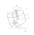
- FIG. 1 is a schematic view showing the configuration of the cellulose acetate production apparatus 1 (hereinafter, also simply referred to as the production apparatus 1) according to the embodiment.
- FIG. 2 is a diagram showing an internal configuration of the manufacturing apparatus 1 of FIG.
- FIG. 3 is a perspective view of the reaction unit 3 of FIG.
- the manufacturing apparatus 1 also serves as a crushing apparatus for crushing pulp, a mixing apparatus for mixing a mixture containing pulp, and a reaction apparatus for acetylating pulp in the mixed solution to produce cellulose acetate.
- the manufacturing apparatus 1 includes a base unit 2, a reaction unit 3, a cover unit 4, a first drive unit 5, an inclination mechanism 6, a rotor (stirring member) 7, a second drive unit 8, and the like. It has a peeling member 9.
- the manufacturing apparatus 1 has an integrated configuration including these components.
- the base unit 2 is provided below the manufacturing apparatus 1 and supports the reaction unit 3 from below.
- the reaction unit 3 has a container 11 and a casing 12 that houses the container 11.
- the container 11 is formed in a bottomed tubular shape and is arranged with the opening 11a facing upward.
- the container 11 has a circular peripheral shape when viewed from the opening direction thereof.
- the inner wall 11b (bottom surface and peripheral surface) of the container 11 is formed smoothly.
- the bottom surface and the peripheral surface of the inner wall 11b are gently continuous.
- the casing 12 covers the outer circumference of the container 11.
- a gap is provided between the container 11 and the casing 12 to avoid interference between the container 11 and the casing 12.
- the casing 12 is pivotally supported by the base unit 2 so as to swing around the axis of the pivot P1 arranged so as to extend in the horizontal direction at one end in the direction perpendicular to the cylinder axis of the container 11.
- the container 11 is rotatably arranged around the cylinder axis by the first drive unit 5 described later.
- the container 11 is configured so that a mixed solution in which pulp is dispersed can be charged.
- This mixed solution contains acetic acid and pulp whose solid content concentration is set to a value in the range of 5% by weight or more and 20% by weight or less, and has a water concentration in the range of 0% by weight or more and 3% by weight or less. Is set to.
- the cover unit 4 is provided above the container 11 and closes the opening 11a of the container 11.
- the cover unit 4 has a close contact portion 14 that is in close contact with the peripheral edge of the opening 11a of the container 11 and is rotatably provided around the cylinder axis of the container 11.
- the close contact portion 14 is brought into close contact with the opening 11a of the container 11, so that the inside of the container 11 is kept in a liquid-tight state.
- the cover unit 4 is supported by the reaction unit 3.
- the cover unit 4 is pivotally supported by the casing 12 at one end in the direction perpendicular to the tubular axis of the container 11 so as to swing around the axis of the pivot P2 arranged so as to extend in the horizontal direction.
- the first drive unit 5 has a motor, and the container 11 is rotated around the cylinder axis at a predetermined rotation speed by the rotational driving force of the motor.
- the first drive unit 5 is arranged below the container 11 and is supported by the reaction unit 3.
- the tilting mechanism 6 adjusts the tubular axis direction of the container 11 between the vertical direction and the direction intersecting the vertical direction.
- the manufacturing apparatus 1 is configured so that the cylindrical axial direction of the container 11 can be adjusted between the vertical direction and the direction intersecting the vertical direction.
- the tilting mechanism 6 is supported by the base unit 2.
- FIG. 1 shows how the cylinder axis CL of the container 11 is arranged so as to coincide with the vertical line VL by setting the tilting mechanism 6.
- the inclination angle ⁇ (see FIGS. 3 and 5 (C)) at which the cylinder axis CL is inclined with respect to the vertical line VL and the horizontal line HL is set, the inclination mechanism 6 is inclined during the operation of the manufacturing apparatus 1. Maintain the angle ⁇ .
- the tilting mechanism 6 has an actuator 15.
- the actuator 15 has a cylinder 16 having one end connected to the base unit 2, and a rod 17 arranged so as to be retractable from the other end of the cylinder 16 and having one end connected to the reaction unit 3.
- the tilting mechanism 6 retracts the rod 17, the tilting angle ⁇ becomes zero, and the cylinder axis CL coincides with the vertical line VL.
- the tilt mechanism 6 extends the rod 17, the tilt angle ⁇ increases, and the cylinder axis CL tilts with respect to the vertical line VL.
- the base unit 2 has an internal space. The first drive unit 5 and the tilting mechanism 6 are housed in this internal space.
- the rotor 7 gives a high shearing force to the pulp in the mixed liquid by stirring the mixed liquid in the container 11, and crushes the pulp in the liquid.
- the rotor 7 extends in the tubular axis direction of the container 11 and is rotatably arranged around the tubular axis in a state where the cover unit 4 is closed.
- One end of the rotor 7 is arranged in the container 11, and the other end is connected to the second drive unit 8.
- the rotor 7 is supported by the second drive unit 8.
- the rotor 7 has a rotor shaft 7a extending in the tubular axis direction, and a stirring unit 7b arranged at one end to stir the mixed solution. Rotational driving force is transmitted from the second drive unit 8 to the rotor shaft 7a. As a result, the rotor 7 rotates around the rotor shaft 7a.
- the stirring portion 7b of the present embodiment has a base portion 7c extending radially from the axial center of the rotor shaft 7a when viewed from the rotor axial direction, and a plurality of shaft portions 7d extending from the base portion 7c in the axial direction of the rotor shaft 7a.
- the cover unit 4 When the cover unit 4 is closed, the axis of the rotor shaft 7a is unevenly distributed at a position separated in the radial direction of the container 11 from the axis of the cylinder shaft of the container 11.
- the rotor 7 is arranged around the cylinder shaft of the container 11 so that the mixed solution can be agitated.
- the second drive unit 8 has a motor, and the rotor 7 is rotated around the rotor shaft 7a at a predetermined rotation speed by the rotational driving force of the motor.
- the second drive unit 8 is arranged above the container 11 and is supported by the cover unit 4.
- the peeling member 9 is arranged so as to peel the pulp adhering to the inner wall 11b of the container 11 from the inner wall 11b and return it to the mixed liquid.
- the peeling member 9 has a blade 18 extending in the tubular axis direction when the cover unit 4 is closed, and a support member 19 for supporting the blade 18. The blade 18 comes into contact with the portion of the inner wall 11b around the cylinder axis of the container 11.
- the position of the peeling member 9 in the manufacturing apparatus 1 is maintained even while the container 11 and the rotor 7 are rotating.
- the blade 18 continuously contacts the peripheral surface of the inner wall 11b of the rotating container 11 in the circumferential direction. As a result, the blade 18 continuously peels off the pulp adhering to the peripheral surface of the inner wall 11b.
- the manufacturing apparatus 1 may include a plurality of peeling members 9 which are arranged apart from each other around the cylinder axis of the container 11 and come into contact with the peripheral surface of the inner wall 11b of the container 11. According to this configuration, the pulp adhering to the inner wall 11b of the container 11 can be peeled off from the inner wall 11b to make it easier to stir the pulp in the mixture.
- the manufacturing apparatus 1 having the above configuration, after crushing the pulp in the container 11, a reaction initiator is added to the mixed solution containing the crushed pulp in the container 11, and acetic anhydride is added in the container 11. It is configured to be able to acetylate pulp cellulose in the presence. That is, the manufacturing apparatus 1 can perform from the crushing of pulp to the production of cellulose acetate by itself. As a result, for example, as compared with the case where the crushing treatment and the acetylation treatment are performed separately in a plurality of different facilities, each treatment can be managed collectively, and cellulose acetate can be stably produced.
- the method for producing cellulose acetate of the present embodiment using this production apparatus 1 will be described.
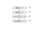
- FIG. 4 is a diagram showing a method for producing cellulose acetate according to the embodiment.
- the production method includes a preparation step S1, a crushing step S2, an acetylation step S3, and a hydrolysis step S4.
- FIG. 5A is a diagram showing the manufacturing apparatus 1 at the time of preparation step S1.
- FIG. 5B is a diagram showing the manufacturing apparatus 1 at the time of the crushing step S2.
- FIG. 5C is a diagram showing the manufacturing apparatus 1 at the time of the acetylation step S3.
- FIG. 6 is a diagram showing a state when the manufacturing apparatus 1 of FIG. 1 is driven. In the above manufacturing method, steps S1 to S4 are performed in this order.
- the operator When producing cellulose acetate using pulp as a raw material, the operator first performs preparation step S1.
- the preparation step S1 the operator contains acetic acid and pulp having a solid content concentration set to a value in the range of 5% by weight or more and 20% by weight or less, and has a water concentration of 0% by weight or more and 3% by weight or less.
- acetic anhydride is further added to this mixed solution.
- the operator can perform the preparation step S1 by charging each component into the container 11 and directly preparing the mixed solution in the container 11. Therefore, the loss of the material due to the transfer of the mixed solution can be reduced.
- the operator seals the inside of the container 11 by closing the cover unit 4 while keeping the peripheral edge of the opening 11a of the container 11 in close contact with the close contact portion 14 (FIG. 5A). This prevents the mixed solution from leaking out of the container 11.
- the operator sets the manufacturing device 1.
- the rotation directions of the container 11 and the rotor 7 are set so as to stir the mixed solution around the cylinder axis of the container 11 inside the container 11.
- the operator arranges the container 11 by the tilting mechanism 6 so that the tubular axis direction is along the vertical direction.
- the inclination angle ⁇ at this time can be set as appropriate, but can be set, for example, in the range of 0 ° or more and 10 ° or less.
- the pulp is crushed by stirring the mixed solution in the container 11 (FIG. 5 (B)).
- acetic anhydride is added to the mixed solution in the preparation step S1. Therefore, in the crushing step S2, the pulp is crushed with acetic anhydride added to the mixed solution. At this point, the acetic anhydride in the mixture does not react with the cellulose in the pulp because the mixture does not contain a reaction initiator.
- the manufacturing apparatus 1 is configured so that the pulp can be crushed by a stirring member in a state where acetic anhydride is added to the mixed solution before acetylating the cellulose of the pulp in the container 11.
- the mixed liquid is agitated around the cylinder shaft of the container 11 inside the container 11 formed in the shape of a bottomed cylinder. Further, in the crushing step S2, the container 11 is arranged so that the tubular axis direction is along the vertical direction. Further, in the crushing step S2, the mixed liquid is agitated by rotating the rotor 7 extending in the tubular axis direction of the container 11 around the tubular axis in the container 11. Further, in the crushing step S2, the pulp adhering to the inner wall 11b of the container 11 is peeled off from the inner wall 11b and returned to the mixed liquid while stirring the mixed liquid.
- the pulp in the mixed solution is strongly agitated in the gap between the rotor 7 and the inner wall 11b of the container 11.
- the base portion 7c and the shaft portion 7d provided on the rotor 7 apply a strong and high shearing force to the mixed liquid.
- the mixed liquid flowing between the rotor 7 and the peeling member 9 in the container 11 is guided by the gap and stirred by the rotor 7.
- the pulp peeled from the inner wall 11b by the peeling member 9 is returned to the mixed liquid, guided by the gap, and stirred by the rotor 7.
- the mixed solution is efficient while increasing the flow velocity of the mixed solution passing through the gap. Stir well. Further, due to its viscosity, the mixed liquid rotates around the cylinder axis of the container 11 as the container 11 rotates, and is efficiently agitated by the rotor 7. In the crushing step S2, the mixed solution is stirred while flowing around the cylinder axis of the container 11 and in the direction of the cylinder axis. Further, the pulp is crushed many times by the rotor 7 to be finely divided and uniformly dispersed in the mixed solution. As a result, the mixed solution changes so that the fluidity gradually decreases.
- the rotation speed of the container 11 and the rotation speed of the rotor 7 in the crushing step S2 can be appropriately set. These rotation speeds can be set according to, for example, the volume of the container 11 and the size and structure of the rotor 7. Further, as an example, the rotation speeds of the container 11 and the rotor 7 can be set within a range in which unnecessary vibration is not generated while the manufacturing apparatus 1 is being driven.
- the rotation speed of the container 11 is preferably a value in the range of 100 rpm or more and 300 rpm or less, and more preferably a value in the range of 150 rpm or more and 200 rpm or less (here, 170 rpm).
- the rotation speed of the rotor 7 is preferably a value in the range of 2000 rpm or more and 4000 rpm or less, and more preferably a value in the range of 2500 rpm or more and 3500 rpm or less (here, 3200 rpm). Further, although the rotation directions of the container 11 and the rotor 7 are set in the same direction in the present embodiment, they may be set in opposite directions.
- the reaction initiator is added to the mixed solution containing the crushed pulp in the container 11, and the cellulose of the pulp is acetylated in the container 11 in the presence of acetic anhydride.
- the reaction initiator catalytic sulfuric acid is used here.
- cellulose is reacted with acetic anhydride to produce completely trisubstituted cellulose acetate (cellulose triacetate) (FIG. 5 (C)).
- the container 11 is arranged so that the tubular axis direction intersects the vertical direction.
- the inclination angle ⁇ at the time of this arrangement can be set as appropriate, but for example, it can be set to a value in the range larger than 0 ° and 45 ° or less.
- a value in the range larger than 0 ° and 45 ° or less for example, an angle in the range of 10 ° or more and 40 ° or less is more desirable, and an angle in the range of 25 ° or more and 35 ° or less (here, 30 °) is more desirable.
- a neutralizing agent is put into the container 11 to neutralize the catalytic sulfuric acid.
- a magnesium acetate solution is used here.
- the completely trisubstituted cellulose acetate in the mixed solution is hydrolyzed to produce cellulose acetate having a desired degree of substitution.
- a large amount of water is added to the mixed solution to precipitate cellulose acetate for solid-liquid separation.
- the cellulose acetate is washed and dried to obtain a product of cellulose acetate.
- the solid content concentration of the pulp in the mixed solution is set to a value in the range of 5% by weight or more and 20% by weight or less, so that water is not added to the mixed solution.
- the pulp can be easily dispersed in the mixed solution.
- a high shearing force is given to the pulp, and the pulp can be crushed in the liquid.
- high-strength pulp having a burst strength of 900 kPa or more can be crushed satisfactorily. Therefore, the pulp can be efficiently crushed without reducing the hydrogen bonds of the pulp in the mixed solution with water.
- the pulp is crushed in the crushing step S2 with acetic anhydride added to the mixed solution.
- acetic anhydride can be added to the mixed solution from the stage of crushing step S2. Therefore, the step of adding acetic anhydride to the mixed solution after the crushing step becomes unnecessary. Therefore, the number of steps can be further reduced, and the production efficiency of cellulose acetate can be improved.
- the amount of the liquid in the mixed solution can be increased without adding water to the mixed solution. This makes it easier to apply a high shearing force to the pulp in the liquid and promotes the crushing of the pulp.
- the mixed solution is agitated around the cylinder axis of the container 11 inside the container 11 formed in the shape of a bottomed cylinder.
- the mixed solution can be agitated more efficiently, and the crushing step S2 can be performed satisfactorily.
- the crushing step S2 can be performed well. It can be carried out. Therefore, even when recycled pulp containing such high-strength pulp is used, cellulose acetate can be efficiently produced. Further, even when softwood pulp having a relatively long fiber length is used, the crushing step S2 can be performed satisfactorily.
- the burst strength of pulp can be measured by, for example, a method based on JIS B P8112.
- the pulp is crushed in the liquid while stirring the mixed liquid, the heat generated when the pulp is crushed can be dispersed in the liquid. As a result, it is possible to prevent the pulp from being scorched during the crushing step S2. Therefore, the pulp can be crushed stably.
- the container 11 is arranged so that the tubular axis direction is along the vertical direction. As a result, in the crushing step S2, it is possible to suppress uneven distribution of the components in the mixed solution due to the influence of gravity, and to facilitate stirring of the mixed solution.
- the container 11 is arranged so that the axial direction intersects the vertical direction. As a result, in the acetylation step S3, the mixed solution in the container 11 can be easily kneaded.
- the mixed solution is agitated by rotating the rotor 7 extending in the tubular axis direction of the container 11 around the tubular axis in the container 11.
- the mixed solution in the container 11 can be efficiently agitated around the cylinder shaft.
- the crushing step S2 the pulp adhering to the inner wall 11b of the container 11 is peeled off from the inner wall 11b and returned to the mixed liquid while stirring the mixed liquid. As a result, even when the pulp in the mixed solution easily adheres to the inner wall 11b of the container 11, the pulp can be easily stirred in the mixed solution. Therefore, the crushing step S2 can be efficiently performed.
- a modified example of the present embodiment will be described.
- FIG. 7 is a diagram partially showing the peeling member 109 according to the first modification.
- the peeling member 109 extends in the tubular axis direction and is perpendicular to the tubular axial direction of the container 11 with the first blade 118 in contact with the peripheral surface of the inner wall 11b when the cover unit 4 is closed. It has a second blade 120 extending in one direction and in contact with the bottom surface of the inner wall 11b. The blades 118 and 120 are supported by the support member 119. According to the peeling member 109, the pulp adhering to the inner wall 11b of the container 11 can be peeled off more efficiently and returned to the mixed solution.
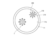
- FIG. 8 is a diagram showing a peeling member 209 according to the second modification.
- the peeling member 209 can rotate together with the rotating shaft 219 extending in the tubular axis direction and the rotating shaft 219 and elastically contact the inner wall 11b of the container 11 when the cover unit 4 is closed. It has a plurality of blades 218 arranged. The plurality of blades 218 extend radially from the rotation shaft 219. The rotating shaft 219 supports each blade 218. The rotational driving force of the second driving unit 8 is transmitted to the rotating shaft 219.
- the plurality of blades 218 of the peeling member 209 come into contact with the inner wall 11b of the rotating container 11 one after another.
- the pulp adhering to the inner wall 11b can be more efficiently peeled off and returned to the mixed solution.
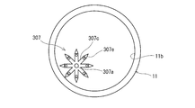
- FIG. 9 is a diagram showing a rotor 307 according to the third modification.
- the rotor 307 is arranged so as to rotate together with the rotor shaft 307a extending in the tubular axis direction and the rotor shaft 307a and elastically contact the inner wall 11b of the container 11 in a state where the cover unit 4 is closed. It also has a plurality of blades 307e. The plurality of blades 307e extend outwardly radially from the base 307c of the rotor 307.
- the rotor 307 has both a function as a stirring member and a function as a peeling member.
- the plurality of blades 307e come into contact with the inner wall 11b of the rotating container 11 one after another.
- the pulp adhering to the inner wall 11b can be more efficiently peeled off and returned to the mixed solution.
- a high-viscosity dope 600 g having a viscosity of 1 million mPa ⁇ s to which a colorant (0.2 g) was added was used as a test mixture, and the above setting was made when the inclination angle ⁇ was 0 °.
- the manufacturing apparatus 1 was put into operation.
- the mixed solution can be mixed almost uniformly in about 60 seconds from the start of rotation of the container 11 and the rotor 7. Further, it was found that when the inclination angle ⁇ was set to 30 °, the mixing condition of the mixed liquid was improved, and the mixed liquid could be mixed almost uniformly in about 40 seconds from the start of rotation of the container 11 and the rotor 7.
- Test 3 The solid content concentration of the pulp in the mixed solution was changed in the range of 5% by weight or more and 20% by weight or less, and the state of the pulp in the mixed solution was confirmed when the crushing step S2 was performed. As a result, it was found that when the amount of pulp is small, the pulp is easily dispersed in the mixed solution, and when the amount of pulp is large, the pulp may be aggregated in the mixed solution. Further, it was found that the pulp was crushed without any problem regardless of whether the pulp was in a dispersed state or an agglutinated state in the mixed solution.
- pulp A1 softwood pulp having a burst strength of 330 kPa (hereinafter referred to as pulp A1) was prepared. Further, as a high-strength pulp having a relatively high burst strength, softwood pulp having a burst strength of 1040 kPa (hereinafter referred to as pulp A2) was prepared. The condition of crushing when these pulps A1 and A2 were crushed in the crushing step S2 under the same conditions was confirmed. In this test, the solid content concentration of the pulps A1 and A2 of the mixed solution prepared in the preparation step S1 was set to 23% by weight.
- Example 1 in which the solid content concentration of the pulp of the mixed solution prepared in the preparation step S1 was 6% by weight and Example 2 in which the solid content concentration of the pulp was 23% by weight were prepared.
- crushing step S2 and acetylation step S3 were sequentially performed under the same conditions. As a result, in Examples 1 and 2, no variation was observed in the degree of the acetylation reaction of cellulose in the obtained mixed solution (doping).
- the present invention is not limited to the embodiments, and its configuration and method can be changed, added, or deleted without departing from the spirit of the present invention.
- Acetic anhydride does not need to be added to the mixture in crushing step S2, and may be added to the mixture in, for example, acetylation step S3.
- the structure of the stirring unit of the rotor is not limited to that of the stirring unit 7b, and can be appropriately set.
- the present invention has an excellent effect of preventing an increase in the number of steps and a work load and improving the production efficiency of cellulose acetate. Therefore, it is beneficial to widely apply the present invention to a method for producing cellulose acetate and an apparatus for producing cellulose acetate, which can exert the significance of this effect.
Landscapes
- Chemical & Material Sciences (AREA)
- Life Sciences & Earth Sciences (AREA)
- Engineering & Computer Science (AREA)
- Biochemistry (AREA)
- Materials Engineering (AREA)
- Health & Medical Sciences (AREA)
- Chemical Kinetics & Catalysis (AREA)
- Medicinal Chemistry (AREA)
- Polymers & Plastics (AREA)
- Organic Chemistry (AREA)
- Polysaccharides And Polysaccharide Derivatives (AREA)
Abstract
酢酸セルロースの製造方法は、酢酸と、固形分濃度が5重量%以上20重量%以下の範囲の値に設定されたパルプとを含有すると共に、水分濃度が0重量%以上3重量%以下の範囲の値に設定された混合液を、容器内で撹拌することにより、パルプを液中で解砕する解砕ステップと、容器内の解砕されたパルプを含有する混合液に反応開始剤を追加し、容器内で、無水酢酸の存在下でパルプのセルロースをアセチル化するアセチル化ステップと、を有する。
Description
本発明は、酢酸セルロースの製造方法及び酢酸セルロース製造装置に関する。
パルプを原料に用いて酢酸セルロースを製造する場合、例えば、パルプを解砕する解砕処理と、解砕したパルプ中のセルロースを酢酸及び無水酢酸等の存在下でアセチル化するアセチル化処理と、アセチル化処理によって得た反応生成物を加水分解する加水分解処理とが順に行われる。
アセチル化処理で生じる反応は、固体であるパルプと液体である酸との固液反応である。従って当該反応を均一に行うためには、解砕処理においてパルプを予め細かく解砕する必要がある。このため解砕処理時には、例えば特許文献1に開示されるように、パルプと水とを含む混合液を調製し、パルプの水素結合を水により低減してパルプを解砕し易くする方法が知られている。
ところで、無水酢酸は混合液中の水と反応することにより消費される。このような無水酢酸の消費を防止するため、例えば上記方法では、混合液に無水酢酸を添加する前に、混合液中の水を予め酢酸で置換して除去する処理が行われる。このため、工程数及び作業負担が増大する。また上記方法では、工程毎に混合液を移動させたり、異なる容器に混合液を移し替える必要がある。このため、材料の損失が生じたり、品質のバラツキが生じるおそれがある。これにより、酢酸セルロースの製造効率を向上させることが困難となる。
また従来の解砕処理では、破裂強度が例えば900kPa以上のパルプを解砕しようとした場合、解砕装置の駆動側と筐体側との間等の間隙にパルプが詰まることがある。このパルプの詰まりが原因となって、パルプの解砕処理が困難となる場合がある。
そこで本発明は、パルプを原料に用いて酢酸セルロースを製造する場合において、工程数及び作業負担の増大を防止すると共に、酢酸セルロースの製造効率の向上を図れるようにすることを目的としている。
本発明の一態様に係る酢酸セルロースの製造方法は、酢酸と、固形分濃度が5重量%以上20重量%以下の範囲の値に設定されたパルプとを含有すると共に、水分濃度が0重量%以上3重量%以下の範囲の値に設定された混合液を、容器内で撹拌することにより、前記パルプを液中で解砕する解砕ステップと、前記容器内の解砕された前記パルプを含有する前記混合液に反応開始剤を追加し、前記容器内で、無水酢酸の存在下で前記パルプのセルロースをアセチル化するアセチル化ステップと、を有する。
上記方法によれば、混合液中のパルプの固形分濃度が5重量%以上20重量%以下の範囲の値に設定されているため、混合液に水を添加しなくても、混合液中にパルプを分散させ易くできる。これにより、解砕ステップにおいて上記混合液を容器内で撹拌することにより、パルプに高いせん断力を与え、パルプを液中で解砕できる。これにより、例えば破裂強度が900kPa以上の高強度パルプも良好に解砕できる。よって、混合液中のパルプの水素結合を水により低減しなくても、パルプを効率よく解砕できる。
また上記方法では、水を実質的に使用しなくて済むため、アセチル化ステップ前において混合液から水を除去する処理が不要である。このため、工程数を削減できる。また、一つの容器内でパルプの解砕ステップ及びアセチル化ステップを行えるため、材料の移し替えを低減できる。これにより、酢酸セルロースの製造効率の向上を図れる。
前記解砕ステップにおいて、前記混合液に無水酢酸を添加した状態で、前記パルプを解砕してもよい。上記方法では、混合液の水分量が非常に少ないため、解砕ステップの段階から混合液に無水酢酸を添加できる。このため、解砕ステップ後に混合液に無水酢酸を添加する工程が不要となる。よって、工程数を更に削減できると共に、酢酸セルロースの製造効率の向上を図れる。
また、解砕ステップの段階で混合液に無水酢酸を添加することで、混合液に水を添加しなくても混合液中の液量を増大できる。これにより、液中でパルプに高いせん断力を与え易くして、パルプの解砕を促進できる。
前記解砕ステップでは、有底筒状に形成された前記容器の内部で、前記容器の筒軸周りに前記混合液を撹拌してもよい。これにより、混合液を一層効率よく撹拌でき、解砕ステップを良好に行える。
前記解砕ステップでは、前記容器を筒軸方向が鉛直方向に沿うように配置してもよい。これにより解砕ステップでは、重力の影響により混合液中の成分が偏在するのを抑制して、混合液を撹拌し易くすることができる。
前記アセチル化ステップでは、前記容器を筒軸方向が鉛直方向と交差するように配置してもよい。これによりアセチル化ステップでは、容器内の混合液を捏ね易くすることができる。
前記解砕ステップでは、前記容器の筒軸方向に延びるロータを前記容器内で前記筒軸周りに回転させることにより前記混合液を撹拌してもよい。これにより、容器内の混合液を容器の筒軸周りに効率よく撹拌できる。
前記解砕ステップでは、前記容器の内壁に付着した前記パルプを前記内壁から剥離して前記混合液中に戻しながら前記混合液を撹拌してもよい。これにより、混合液中のパルプが容器の内壁に付着し易い場合であっても、パルプを混合液中で撹拌し易くすることができる。よって、解砕ステップを効率よく行える。
本発明の一態様に係る酢酸セルロース製造装置は、酢酸と、固形分濃度が5重量%以上20重量%以下の範囲の値に設定されたパルプとを含有すると共に、水分濃度が0重量%以上3重量%以下の範囲の値に設定された混合液が投入される容器と、前記混合液を前記容器内で撹拌することにより、前記パルプを液中で解砕する撹拌部材と、を備え、前記容器内の解砕された前記パルプを含有する前記混合液に反応開始剤を追加し、前記容器内で、無水酢酸の存在下で前記パルプのセルロースをアセチル化可能に構成されている。
上記構成によれば、混合液中のパルプの固形分濃度が5重量%以上20重量%以下の範囲の値に設定されているため、混合液に水を添加しなくても、混合液中にパルプを分散させ易くできる。これにより、上記混合液を容器内で撹拌することにより、混合液中のパルプに高いせん断力を与え、パルプを液中で解砕できる。よって、混合液中のパルプの水素結合を水により低減しなくても、パルプを効率よく解砕できる。また、水を実質的に使用しなくて済むため、パルプのセルロースをアセチル化する前に混合液から水を除去する工程が不要である。このため、パルプ製造時の工程数を削減できる。また、一つの容器でパルプの解砕ステップ及びアセチル化ステップを行えるため、材料の移し替えを低減できる。これにより、酢酸セルロースの製造効率の向上を図れる。
前記容器内で、前記パルプのセルロースをアセチル化する前に、前記混合液に無水酢酸を添加した状態で、前記パルプを前記撹拌部材により解砕可能に構成されていてもよい。このように、上記構成によれば、混合液の水分量が非常に少ないため、パルプをアセチル化する前の段階から混合液に無水酢酸を添加できる。このため、パルプを解砕した後に混合液に無水酢酸を添加する工程が不要となる。よって、工程数を更に削減できると共に、酢酸セルロースの製造効率の向上を図れる。
また、パルプを解砕する際に混合液に無水酢酸が添加されることで、混合液に水を添加しなくても混合液中の液量を増大できる。これにより、液中でパルプに高いせん断力を与え易くして、パルプの解砕を促進できる。
前記容器は、有底筒状に形成され、前記撹拌部材は、前記容器の筒軸周りに前記混合液を撹拌可能に配置されていてもよい。これにより、混合液を一層効率よく撹拌でき、パルプの解砕を良好に行える。
前記容器の筒軸方向が、鉛直方向と、前記鉛直方向に対して交差する方向との間で調整可能に構成されていてもよい。これにより、例えばパルプの解砕ステップでは、容器を筒軸方向が鉛直方向に沿うように配置することで、重力の影響により混合液中の成分が偏在するのを抑制して、混合液を撹拌し易くすることができる。またアセチル化ステップでは、容器を筒軸方向が鉛直方向と交差するように配置することで、混合液を捏ね易くすることができる。
前記撹拌部材は、前記容器の筒軸方向に延び且つ前記筒軸周りに回転可能に配置されていてもよい。これにより、容器内の混合液を容器の筒軸周りに効率よく撹拌できる。
前記容器の内壁に付着した前記パルプを前記内壁から剥離して前記混合液中に戻すように配置された剥離部材を更に備えていてよい。これにより、混合液中のパルプが容器の内壁に付着し易い場合であっても、パルプを混合液中で撹拌し易くすることができる。よって、パルプの解砕を効率よく行える。
本発明の各態様によれば、パルプを原料に用いて酢酸セルロースを製造する場合において、工程数及び作業負担の増大を防止できると共に、酢酸セルロースの製造効率の向上を図ることができる。
(実施形態)
本発明の実施形態について、図を参照して説明する。
[酢酸セルロース製造装置]
図1は、実施形態に係る酢酸セルロース製造装置1(以下、単に製造装置1とも称する。)の構成を示す概要図である。図2は、図1の製造装置1の内部構成を示す図である。図3は、図1の反応ユニット3の斜視図である。製造装置1は、パルプを解砕する解砕装置と、パルプを含有する混合液を混合する混合装置と、混合液中のパルプをアセチル化して酢酸セルロースを生成する反応装置を兼ねている。
本発明の実施形態について、図を参照して説明する。
[酢酸セルロース製造装置]
図1は、実施形態に係る酢酸セルロース製造装置1(以下、単に製造装置1とも称する。)の構成を示す概要図である。図2は、図1の製造装置1の内部構成を示す図である。図3は、図1の反応ユニット3の斜視図である。製造装置1は、パルプを解砕する解砕装置と、パルプを含有する混合液を混合する混合装置と、混合液中のパルプをアセチル化して酢酸セルロースを生成する反応装置を兼ねている。
図1~3に示すように、製造装置1は、ベースユニット2、反応ユニット3、カバーユニット4、第1駆動ユニット5、傾斜機構6、ロータ(撹拌部材)7、第2駆動ユニット8、及び剥離部材9を有する。製造装置1は、これらの構成要素が備わった一体的構成を有する。
ベースユニット2は、製造装置1の下側に設けられ、反応ユニット3を下方から支持する。反応ユニット3は、容器11と、容器11を収容するケーシング12とを有する。
容器11は有底筒状に形成され、開口11aを上方に向けて配置されている。一例として、容器11は、その開口方向から見て円形の周縁形状を有する。容器11の内壁11b(底面及び周面)は、平滑に形成されている。内壁11bの底面と周面とは、緩やかに連続している。
ケーシング12は、容器11の外周を覆っている。容器11とケーシング12との間には隙間が設けられ、容器11とケーシング12との干渉が回避されている。ケーシング12は、容器11の筒軸に垂直な方向の一端において、水平方向に延びるように配置された枢軸P1の軸周りに揺動自在にベースユニット2に軸支されている。
容器11は、後述する第1駆動ユニット5により、その筒軸周りに回転自在に配置されている。容器11は、パルプが分散された混合液を投入可能に構成されている。この混合液は、酢酸と、固形分濃度が5重量%以上20重量%以下の範囲の値に設定されたパルプとを含有すると共に、水分濃度が0重量%以上3重量%以下の範囲の値に設定される。
カバーユニット4は、容器11の上方に設けられ、容器11の開口11aを閉塞する。カバーユニット4は、容器11の開口11aの周縁と密着し且つ容器11の筒軸周りに回転自在に設けられた密着部14を有する。
容器11の開口11aに密着部14が密着することで、容器11は、内部が液密状態に保持される。カバーユニット4は、反応ユニット3に支持されている。一例としてカバーユニット4は、容器11の筒軸に垂直な方向の一端において、水平方向に延びるように配置された枢軸P2の軸周りに揺動自在にケーシング12に軸支されている。
第1駆動ユニット5は、モータを有し、当該モータの回転駆動力により所定の回転数で容器11を筒軸周りに回転させる。第1駆動ユニット5は、容器11の下方に配置され、反応ユニット3に支持されている。
傾斜機構6は、容器11の筒軸方向を、鉛直方向と、鉛直方向に対して交差する方向との間で調整する。これにより製造装置1は、容器11の筒軸方向が、鉛直方向と、鉛直方向に対して交差する方向との間で調整可能に構成されている。傾斜機構6は、ベースユニット2に支持されている。
図1では、傾斜機構6を設定することにより、容器11の筒軸線CLが鉛直線VLと一致するように配置された様子を示している。傾斜機構6は、筒軸線CLが鉛直線VL及び水平線HLに対して傾斜する傾斜角度θ(図3,図5(C)参照)が設定された場合、製造装置1の稼働中において、その傾斜角度θを維持する。
一例として傾斜機構6は、アクチュエータ15を有する。アクチュエータ15は、ベースユニット2に一端が連結されたシリンダ16と、シリンダ16の他端から出退自在に配置されて反応ユニット3に一端が連結されたロッド17とを有する。傾斜機構6がロッド17を退避させると、傾斜角度θがゼロとなり、筒軸線CLが鉛直線VLと一致する。また傾斜機構6がロッド17を伸長させると、傾斜角度θが増大し、筒軸線CLが鉛直線VLに対して傾斜する。ここでベースユニット2は、内部空間を有する。この内部空間には、第1駆動ユニット5と傾斜機構6とが収容される。
ロータ7は、混合液を容器11内で撹拌することにより、混合液中のパルプに高いせん断力を与え、パルプを液中で解砕する。ロータ7は、カバーユニット4が閉じられた状態において、容器11の筒軸方向に延び且つ筒軸周りに回転可能に配置されている。ロータ7は、一端が容器11内に配置され、他端が第2駆動ユニット8に接続されている。ロータ7は、第2駆動ユニット8に支持されている。ロータ7は、筒軸方向に延びるロータ軸7aと、一端に配置されて混合液を撹拌する撹拌部7bとを有する。ロータ軸7aには、第2駆動ユニット8から回転駆動力が伝達される。これによりロータ7は、ロータ軸7a周りに回転する。
本実施形態の撹拌部7bは、ロータ軸方向から見てロータ軸7aの軸心から放射状に延びる基部7cと、基部7cからロータ軸7aの軸方向に延びる複数の軸部7dとを有する。カバーユニット4が閉じられた状態において、ロータ軸7aの軸心は、容器11の筒軸の軸心に対して容器11の径方向に離隔した位置に偏在している。一例としてロータ7は、容器11の筒軸周りに混合液を撹拌可能に配置されている。
第2駆動ユニット8は、モータを有し、当該モータの回転駆動力により所定の回転数でロータ7をロータ軸7a周りに回転させる。第2駆動ユニット8は、容器11の上方に配置され、カバーユニット4に支持されている。
剥離部材9は、容器11の内壁11bに付着したパルプを内壁11bから剥離して混合液中に戻すように配置されている。剥離部材9は、一例として、カバーユニット4が閉じられた状態において筒軸方向に延びるブレード18と、ブレード18を支持する支持部材19とを有する。ブレード18は、容器11の筒軸周りの内壁11bの部分と接触する。
剥離部材9がカバーユニット4に支持されることにより、容器11及びロータ7の回転中でも、製造装置1内での剥離部材9の位置は保持される。ブレード18は、回転中の容器11の内壁11bの周面と周方向に連続的に接触する。これによりブレード18は、内壁11bの周面に付着したパルプを連続して剥離する。
なお製造装置1は、容器11の筒軸周りに離隔して配置されて容器11の内壁11bの周面と接触する複数の剥離部材9を備えていてもよい。当該構成によれば、容器11の内壁11bに付着したパルプを内壁11bから剥離して、混合液中でパルプを一層撹拌し易くすることができる。
上記構成を有する製造装置1は、容器11内でパルプを解砕した後、容器11内の解砕されたパルプを含有する混合液に反応開始剤を追加し、容器11内で、無水酢酸の存在下でパルプのセルロースをアセチル化可能に構成されている。即ち製造装置1は、パルプの解砕から酢酸セルロースの生成までを単体で行うことができる。これにより、例えば、解砕処理とアセチル化処理とを異なる複数の設備で別々に行う場合に比べて、各処理を一括して管理でき、酢酸セルロースを安定して製造できる。以下、この製造装置1を用いた本実施形態の酢酸セルロースの製造方法について説明する。
[酢酸セルロースの製造方法]
図4は、実施形態に係る酢酸セルロースの製造方法を示す図である。図4に示すように、当該製造方法は、準備ステップS1、解砕ステップS2、アセチル化ステップS3、及び加水分解ステップS4を有する。図5(A)は、準備ステップS1時の製造装置1を示す図である。図5(B)は、解砕ステップS2時の製造装置1を示す図である。図5(C)は、アセチル化ステップS3時の製造装置1を示す図である。図6は、図1の製造装置1の駆動時の様子を示す図である。上記製造方法では、各ステップS1~S4が、この順に行われる。
図4は、実施形態に係る酢酸セルロースの製造方法を示す図である。図4に示すように、当該製造方法は、準備ステップS1、解砕ステップS2、アセチル化ステップS3、及び加水分解ステップS4を有する。図5(A)は、準備ステップS1時の製造装置1を示す図である。図5(B)は、解砕ステップS2時の製造装置1を示す図である。図5(C)は、アセチル化ステップS3時の製造装置1を示す図である。図6は、図1の製造装置1の駆動時の様子を示す図である。上記製造方法では、各ステップS1~S4が、この順に行われる。
パルプを原料に用いて酢酸セルロースを製造する場合、オペレータは、最初に準備ステップS1を行う。準備ステップS1では、オペレータは、酢酸と、固形分濃度が5重量%以上20重量%以下の範囲の値に設定されたパルプとを含有すると共に、水分濃度が0重量%以上3重量%以下の範囲の値に設定された混合液を準備する。本実施形態では、この混合液に更に無水酢酸を添加する。
ここでオペレータは、容器11内に各成分を投入し、容器11内において混合液を直接調製することにより準備ステップS1を行える。このため、混合液の移し替えに伴う材料の損失を低減できる。オペレータは、容器11内に混合液を投入した後、容器11の開口11aの周縁を密着部14に密着させながらカバーユニット4を閉じることで容器11内を密閉する(図5(A))。これにより、混合液が容器11外に漏出するのを防止する。
次にオペレータは、製造装置1の設定を行う。ここでは、容器11の内部で、容器11の筒軸周りに混合液を撹拌するように、容器11とロータ7との各回転方向を設定する。またオペレータは、傾斜機構6により、容器11を筒軸方向が鉛直方向に沿うように配置する。このときの傾斜角度θは適宜設定可能であるが、例えば0°以上10°以下の範囲で設定できる。
解砕ステップS2では、混合液を容器11内で撹拌することにより、パルプを解砕する(図5(B))。本実施形態では、準備ステップS1において、混合液に無水酢酸が添加されている。従って、解砕ステップS2において、混合液に無水酢酸を添加した状態で、パルプを解砕する。この時点では、混合液に反応開始剤が含まれていないので、混合液中の無水酢酸とパルプのセルロースとは反応しない。
このように製造装置1は、容器11内で、パルプのセルロースをアセチル化する前に、混合液に無水酢酸を添加した状態で、パルプを撹拌部材により解砕可能に構成されている。
また、オペレータが上記設定を行うことで、解砕ステップS2では、有底筒状に形成された容器11の内部で、容器11の筒軸周りに混合液を撹拌する。また解砕ステップS2では、容器11を筒軸方向が鉛直方向に沿うように配置する。また解砕ステップS2では、容器11の筒軸方向に延びるロータ7を容器11内で筒軸周りに回転させることにより混合液を撹拌する。また解砕ステップS2では、容器11の内壁11bに付着したパルプを内壁11bから剥離して混合液中に戻しながら混合液を撹拌する。
図6に示すように、容器11の内部では、混合液中のパルプが、ロータ7と容器11の内壁11bとが近接する間の間隙において強く撹拌される。本実施形態では、ロータ7に設けられた基部7cと軸部7dとにより、混合液に激しい高いせん断力が与えられる。また、容器11中のロータ7と剥離部材9との間を流通する混合液が、前記間隙に案内されてロータ7により撹拌される。また、剥離部材9により内壁11bから剥離されたパルプが混合液中に戻され、前記間隙に案内されてロータ7により撹拌される。
また本実施形態では、ロータ7のロータ軸7aの軸心が、容器11の筒軸の軸心に対して偏心しているため、前記間隙を通過する混合液の流速を高めながら、混合液が効率よく撹拌される。また混合液は、その粘性により、容器11の回転と共に容器11の筒軸周りに回転し、ロータ7により効率よく撹拌される。解砕ステップS2において、混合液は、容器11の筒軸周り及び筒軸方向に流動しながら撹拌される。またパルプは、ロータ7により何度も砕かれながら細かくなり、混合液中に均一に分散される。これにより混合液は、流動性が次第に減少するように変化する。
解砕ステップS2における容器11の回転速度とロータ7の回転速度とは、適宜設定可能である。これらの回転速度は、例えば、容器11の容積やロータ7のサイズ・構造等に応じて設定できる。また一例として、容器11及びロータ7の各回転速度は、製造装置1が駆動中に不要な振動を生じない範囲内で設定できる。
一例として、容器11の回転速度は、100rpm以上300rpm以下の範囲内の値であることが望ましく、150rpm以上200rpm以下の範囲内の値(ここでは170rpm)であることが一層望ましい。
また一例として、ロータ7の回転速度は、2000rpm以上4000rpm以下の範囲内の値であることが望ましく、2500rpm以上3500rpm以下の範囲内の値(ここでは3200rpm)であることが一層望ましい。また容器11及びロータ7の各回転方向は、本実施形態では同方向に設定しているが、逆方向に設定してもよい。
アセチル化ステップS3では、容器11内の解砕されたパルプを含有する混合液に反応開始剤を追加すると共に、容器11内で、無水酢酸の存在下でパルプのセルロースをアセチル化する。反応開始剤としては、ここでは触媒硫酸を用いる。これにより、セルロースと無水酢酸を反応させ、完全三置換セルロースアセテート(三酢酸セルロース)を生成させる(図5(C))。
本実施形態のアセチル化ステップS3では、容器11を筒軸方向が鉛直方向と交差するように配置する。この配置時の傾斜角度θは適宜設定可能であるが、例えば0°より大きく45°以下の範囲の値に設定できる。傾斜角度θは、例えば、10°以上40°以下の範囲の角度がより望ましく、25°以上35°以下の範囲の角度(ここでは30°)が一層望ましい。
加水分解ステップS4では、容器11内に中和剤を投入して触媒硫酸を中和する。中和剤としては、ここでは酢酸マグネシウム溶液を用いる。その後、混合液中の完全三置換セルロースアセテートを加水分解することにより、所望の置換度の酢酸セルロースを生成させる。その後、混合液に多量の水を添加し、酢酸セルロースを沈殿させて固液分離する。その後、酢酸セルロースを洗浄及び乾燥することで、酢酸セルロースの製品を得る。
以上説明したように、上記方法によれば、混合液中のパルプの固形分濃度が5重量%以上20重量%以下の範囲の値に設定されているため、混合液に水を添加しなくても、混合液中にパルプを分散させ易くできる。これにより、解砕ステップS2において混合液を容器11内で撹拌することにより、パルプに高いせん断力を与え、パルプを液中で解砕できる。これにより、例えば破裂強度が900kPa以上の高強度パルプも良好に解砕できる。よって、混合液中のパルプの水素結合を水により低減しなくても、パルプを効率よく解砕できる。
また上記方法では、水を実質的に使用しなくて済むため、アセチル化ステップS3前において混合液から水を除去する処理が不要である。このため、工程数を削減できる。また、一つの容器11内でパルプの解砕ステップS2及びアセチル化ステップS3を行えるため、材料の移し替えを低減できる。これにより、酢酸セルロースの製造効率の向上を図れる。
また上記方法では、解砕ステップS2において、混合液に無水酢酸を添加した状態で、パルプを解砕する。この方法では、混合液の水分量が非常に少ないため、解砕ステップS2の段階から混合液に無水酢酸を添加できる。このため、解砕ステップ後に混合液に無水酢酸を添加する工程が不要となる。よって、工程数を更に削減できると共に、酢酸セルロースの製造効率の向上を図れる。
また、解砕ステップS2の段階で混合液に無水酢酸を添加することで、混合液に水を添加しなくても混合液中の液量を増大できる。これにより、液中でパルプに高いせん断力を与え易くして、パルプの解砕を促進できる。
また解砕ステップS2では、有底筒状に形成された容器11の内部で、容器11の筒軸周りに混合液を撹拌する。これにより、混合液を一層効率よく撹拌でき、解砕ステップS2を良好に行える。
よってパルプとして、例えば破裂強度が900kPa以上1040kPa以下の範囲の値(他の例として、900kPa以上2000kPa以下の範囲の値)に設定された高強度パルプを用いても、解砕ステップS2を良好に行うことができる。従って、このような高強度パルプを含む再生パルプを用いた場合でも、酢酸セルロースを効率よく製造できる。また、繊維長が比較的長い針葉樹パルプを用いた場合でも、解砕ステップS2を良好に行える。なお、パルプの破裂強度は、例えばJIS B P8112に準拠した方法により測定できる。
また、混合液を撹拌しながら液中でパルプを解砕するため、パルプの解砕時に発生する熱を液中に分散させることができる。これにより解砕ステップS2時にパルプが焦げ付くのを防止できる。よって、パルプを安定して解砕できる。
また解砕ステップS2では、容器11を筒軸方向が鉛直方向に沿うように配置する。これにより、解砕ステップS2では、重力の影響により混合液中の成分が偏在するのを抑制して、混合液を撹拌し易くすることができる。
またアセチル化ステップS3では、容器11を筒軸方向が鉛直方向と交差するように配置する。これによりアセチル化ステップS3では、容器11内の混合液を捏ね易くすることができる。
また解砕ステップS2では、容器11の筒軸方向に延びるロータ7を容器11内で筒軸周りに回転させることにより混合液を撹拌する。これにより、容器11内の混合液を筒軸周りに効率よく撹拌できる。
また解砕ステップS2では、容器11の内壁11bに付着したパルプを内壁11bから剥離して混合液中に戻しながら混合液を撹拌する。これにより、混合液中のパルプが容器11の内壁11bに付着し易い場合であっても、パルプを混合液中で撹拌し易くすることができる。よって、解砕ステップS2を効率よく行える。以下、本実施形態の変形例について説明する。
図7は、第1変形例に係る剥離部材109を部分的に示す図である。図7に示すように、剥離部材109は、カバーユニット4が閉じられた状態において、筒軸方向に延び且つ内壁11bの周面と接触する第1ブレード118と、容器11の筒軸方向に垂直な一方向に延び且つ内壁11bの底面と接触する第2ブレード120とを有する。ブレード118,120は、支持部材119により支持されている。この剥離部材109によれば、容器11の内壁11bに付着したパルプを一層効率よく剥離して混合液に戻すことができる。
図8は、第2変形例に係る剥離部材209を示す図である。図8に示すように、剥離部材209は、カバーユニット4が閉じられた状態において、筒軸方向に延る回転軸219と、回転軸219と共に回転し且つ容器11の内壁11bと弾性接触可能に配置された複数のブレード218とを有する。複数のブレード218は、回転軸219から放射状に延びている。回転軸219は、各ブレード218を支持している。回転軸219には、第2駆動ユニット8の回転駆動力が伝達される。
上記構成によれば、酢酸セルロース製造装置の駆動時には、剥離部材209の複数のブレード218が、回転中の容器11の内壁11bと次々に接触する。これにより、内壁11bに付着したパルプを更に効率よく剥離して混合液に戻すことができる。
図9は、第3変形例に係るロータ307を示す図である。図9に示すように、ロータ307は、カバーユニット4が閉じられた状態において、筒軸方向に延びるロータ軸307aと、ロータ軸307aと共に回転し且つ容器11の内壁11bと弾性接触可能に配置された複数のブレード307eとを有する。複数のブレード307eは、ロータ307の基部307cから外方に向けて放射状に延びている。ロータ307は、撹拌部材としての機能と、剥離部材としての機能とを兼ねている。
上記構成によれば、酢酸セルロース製造装置の駆動時には、複数のブレード307eが、回転中の容器11の内壁11bと次々に接触する。これにより、内壁11bに付着したパルプを更に効率よく剥離して混合液に戻すことができる。
[確認試験]
次に、確認試験について説明するが、本発明は以下に示す各実施例に限定されるものではない。
(試験1)
まず、準備ステップS1において、酢酸と、固形分濃度が23重量%に設定されたパルプとを含有すると共に、水分濃度が0重量%以上3重量%以下の範囲の値に設定された混合液を準備した。この混合液を用いて解砕ステップS2を一定時間行った。
次に、確認試験について説明するが、本発明は以下に示す各実施例に限定されるものではない。
(試験1)
まず、準備ステップS1において、酢酸と、固形分濃度が23重量%に設定されたパルプとを含有すると共に、水分濃度が0重量%以上3重量%以下の範囲の値に設定された混合液を準備した。この混合液を用いて解砕ステップS2を一定時間行った。
これにより得られたパルプ解砕済み混合液(スラリー)を目視で確認したところ、パルプの未解砕片は見られなかった。また、当該混合液を用いてアセチル化ステップS3を行ったところ、問題なくセルロースのアセチル化が行われることが分かった。
(試験2)
解砕ステップS2に先立ち、製造装置1を以下の内容で設定した。
容器11の回転速度:170rpm
ロータ7の回転速度:3200rpm
容器11とロータ7との回転方向:同一方向
容器11の方向に対する筒軸の傾斜角度θ:0°
上記設定にて解砕ステップS2を行った際の製造装置1の状態を監視した。その結果、容器11からの液漏れは見られず、製造装置1の不要な振動も発生しないことが分かった。また、解砕ステップS2後の混合液中のパルプの解砕状態も良好であった。
解砕ステップS2に先立ち、製造装置1を以下の内容で設定した。
容器11の回転速度:170rpm
ロータ7の回転速度:3200rpm
容器11とロータ7との回転方向:同一方向
容器11の方向に対する筒軸の傾斜角度θ:0°
上記設定にて解砕ステップS2を行った際の製造装置1の状態を監視した。その結果、容器11からの液漏れは見られず、製造装置1の不要な振動も発生しないことが分かった。また、解砕ステップS2後の混合液中のパルプの解砕状態も良好であった。
また、粘度が100万mPa・sの高粘度ドープ(600g)に着色剤(0.2g)を添加したものを試験用の混合液として用い、傾斜角度θが0°の状態で、上記設定にて製造装置1を稼働させた。
その結果、容器11及びロータ7の回転開始から60秒程度で混合液をほぼ均一に混合できることが分かった。また、傾斜角度θを30°に設定すると、混合液の混合具合が向上し、容器11及びロータ7の回転開始から40秒程度で混合液をほぼ均一に混合できることが分かった。
(試験3)
混合液中のパルプの固形分濃度を5重量%以上20重量%以下の範囲で変化させ、解砕ステップS2を行ったときの混合液中のパルプの状態を確認した。その結果、パルプの量が少ない場合、混合液中にパルプが分散し易くなり、パルプの量が多い場合、混合液中で凝集する場合があることが分かった。また、このように混合液中でパルプが分散状態又は凝集状態のうちいずれの状態となる場合も、パルプの解砕は問題なく行われることが分かった。
混合液中のパルプの固形分濃度を5重量%以上20重量%以下の範囲で変化させ、解砕ステップS2を行ったときの混合液中のパルプの状態を確認した。その結果、パルプの量が少ない場合、混合液中にパルプが分散し易くなり、パルプの量が多い場合、混合液中で凝集する場合があることが分かった。また、このように混合液中でパルプが分散状態又は凝集状態のうちいずれの状態となる場合も、パルプの解砕は問題なく行われることが分かった。
(試験4)
破裂強度が通常のものであるパルプとして、破裂強度が330kPaの針葉樹パルプ(以下、パルプA1と称する。)を用意した。また、破裂強度が比較的高い高強度パルプとして、破裂強度が1040kPaの針葉樹パルプ(以下、パルプA2と称する。)を用意した。これらのパルプA1,A2をそれぞれ同一条件の解砕ステップS2で解砕した場合の解砕の具合を確認した。当該試験では、準備ステップS1において準備する混合液のパルプA1,A2の固形分濃度を23重量%に設定した。
破裂強度が通常のものであるパルプとして、破裂強度が330kPaの針葉樹パルプ(以下、パルプA1と称する。)を用意した。また、破裂強度が比較的高い高強度パルプとして、破裂強度が1040kPaの針葉樹パルプ(以下、パルプA2と称する。)を用意した。これらのパルプA1,A2をそれぞれ同一条件の解砕ステップS2で解砕した場合の解砕の具合を確認した。当該試験では、準備ステップS1において準備する混合液のパルプA1,A2の固形分濃度を23重量%に設定した。
その結果、パルプA1,A2のいずれについても、解砕ステップS2後の混合液中に最大寸法が1mm以上の未解砕片が残留することもなく、良好に解砕できることが分かった。
(試験5)
準備ステップS1において準備する混合液のパルプの固形分濃度が6重量%である実施例1と、当該パルプの固形分濃度が23重量%である実施例2とを準備した。この実施例1,2について、同一条件で解砕ステップS2とアセチル化ステップS3とを順に行った。その結果、実施例1,2では、得られた混合液(ドープ)中のセルロースのアセチル化反応の具合にばらつきは見られなかった。
準備ステップS1において準備する混合液のパルプの固形分濃度が6重量%である実施例1と、当該パルプの固形分濃度が23重量%である実施例2とを準備した。この実施例1,2について、同一条件で解砕ステップS2とアセチル化ステップS3とを順に行った。その結果、実施例1,2では、得られた混合液(ドープ)中のセルロースのアセチル化反応の具合にばらつきは見られなかった。
本発明は、実施形態に限定されるものではなく、本発明の趣旨を逸脱しない範囲で、その構成及び方法を変更、追加、又は削除できる。無水酢酸は、解砕ステップS2で混合液に追加する必要はなく、例えばアセチル化ステップS3で混合液に追加してもよい。またロータの撹拌部の構造は、撹拌部7bのものに限定されず、適宜設定可能である。
以上のように本発明は、パルプを原料に用いて酢酸セルロースを製造する場合において、工程数及び作業負担の増大を防止できると共に、酢酸セルロースの製造効率の向上を図れる優れた効果を有する。従って、この効果の意義を発揮できる酢酸セルロースの製造方法及び酢酸セルロース製造装置に本発明を広く適用すると有益である。
1 酢酸セルロース製造装置
6 傾斜機構
7,307 ロータ(撹拌部材)
9,109,209 剥離部材
11 容器
6 傾斜機構
7,307 ロータ(撹拌部材)
9,109,209 剥離部材
11 容器
Claims (13)
- 酢酸と、固形分濃度が5重量%以上20重量%以下の範囲の値に設定されたパルプとを含有すると共に、水分濃度が0重量%以上3重量%以下の範囲の値に設定された混合液を、容器内で撹拌することにより、前記パルプを液中で解砕する解砕ステップと、
前記容器内の解砕された前記パルプを含有する前記混合液に反応開始剤を追加し、前記容器内で、無水酢酸の存在下で前記パルプのセルロースをアセチル化するアセチル化ステップと、を有する、酢酸セルロースの製造方法。 - 前記解砕ステップにおいて、前記混合液に無水酢酸を添加した状態で、前記パルプを解砕する、請求項1に記載の酢酸セルロースの製造方法。
- 前記解砕ステップでは、有底筒状に形成された前記容器の内部で、前記容器の筒軸周りに前記混合液を撹拌する、請求項1又は2に記載の酢酸セルロースの製造方法。
- 前記解砕ステップでは、前記容器を筒軸方向が鉛直方向に沿うように配置する、請求項3に記載の酢酸セルロースの製造方法。
- 前記アセチル化ステップでは、前記容器を筒軸方向が鉛直方向と交差するように配置する、請求項3又は4に記載の酢酸セルロースの製造方法。
- 前記解砕ステップでは、前記容器の筒軸方向に延びるロータを前記容器内で前記筒軸周りに回転させることにより前記混合液を撹拌する、請求項3又は4に記載の酢酸セルロースの製造方法。
- 前記解砕ステップでは、前記容器の内壁に付着した前記パルプを前記内壁から剥離して前記混合液中に戻しながら前記混合液を撹拌する、請求項1~6のいずれか1項に記載の酢酸セルロースの製造方法。
- 酢酸と、固形分濃度が5重量%以上20重量%以下の範囲の値に設定されたパルプとを含有すると共に、水分濃度が0重量%以上3重量%以下の範囲の値に設定された混合液が投入される容器と、
前記混合液を前記容器内で撹拌することにより、前記パルプを液中で解砕する撹拌部材と、を備え、
前記容器内で、解砕された前記パルプを含有する前記混合液に反応開始剤を追加し且つ無水酢酸の存在下で前記パルプのセルロースをアセチル化可能に構成されている、酢酸セルロース製造装置。 - 前記容器内で、前記パルプのセルロースをアセチル化する前に、前記混合液に無水酢酸を添加した状態で、前記パルプを前記撹拌部材により解砕可能に構成されている、請求項8に記載の酢酸セルロース製造装置。
- 前記容器は、有底筒状に形成され、
前記撹拌部材は、前記容器の筒軸周りに前記混合液を撹拌可能に配置されている、請求項8又は9に記載の酢酸セルロース製造装置。 - 前記容器の筒軸方向が、鉛直方向と、前記鉛直方向に対して交差する方向との間で調整可能に構成されている、請求項10に記載の酢酸セルロース製造装置。
- 前記撹拌部材は、前記容器の筒軸方向に延び且つ前記筒軸周りに回転可能に配置されている、請求項10又は11に記載の酢酸セルロース製造装置。
- 前記容器の内壁に付着した前記パルプを前記内壁から剥離して前記混合液中に戻すように配置された剥離部材を更に備える、請求項8~12のいずれか1項に記載の酢酸セルロース製造装置。
Priority Applications (1)
| Application Number | Priority Date | Filing Date | Title |
|---|---|---|---|
| PCT/JP2019/023649 WO2020250418A1 (ja) | 2019-06-14 | 2019-06-14 | 酢酸セルロースの製造方法及び酢酸セルロース製造装置 |
Applications Claiming Priority (1)
| Application Number | Priority Date | Filing Date | Title |
|---|---|---|---|
| PCT/JP2019/023649 WO2020250418A1 (ja) | 2019-06-14 | 2019-06-14 | 酢酸セルロースの製造方法及び酢酸セルロース製造装置 |
Publications (1)
| Publication Number | Publication Date |
|---|---|
| WO2020250418A1 true WO2020250418A1 (ja) | 2020-12-17 |
Family
ID=73780763
Family Applications (1)
| Application Number | Title | Priority Date | Filing Date |
|---|---|---|---|
| PCT/JP2019/023649 Ceased WO2020250418A1 (ja) | 2019-06-14 | 2019-06-14 | 酢酸セルロースの製造方法及び酢酸セルロース製造装置 |
Country Status (1)
| Country | Link |
|---|---|
| WO (1) | WO2020250418A1 (ja) |
Citations (4)
| Publication number | Priority date | Publication date | Assignee | Title |
|---|---|---|---|---|
| JP2006249347A (ja) * | 2005-03-14 | 2006-09-21 | Toray Ind Inc | セルロースエステルの製造方法 |
| WO2012120971A1 (ja) * | 2011-03-04 | 2012-09-13 | 国立大学法人京都大学 | 透明樹脂複合材料 |
| WO2017155054A1 (ja) * | 2016-03-11 | 2017-09-14 | 国立大学法人北海道大学 | セルロースアセテート繊維、セルロースアセテート組成物、およびそれらの製造方法 |
| JP2018131573A (ja) * | 2017-02-17 | 2018-08-23 | 日本製紙株式会社 | ゴム組成物の製造方法 |
-
2019
- 2019-06-14 WO PCT/JP2019/023649 patent/WO2020250418A1/ja not_active Ceased
Patent Citations (4)
| Publication number | Priority date | Publication date | Assignee | Title |
|---|---|---|---|---|
| JP2006249347A (ja) * | 2005-03-14 | 2006-09-21 | Toray Ind Inc | セルロースエステルの製造方法 |
| WO2012120971A1 (ja) * | 2011-03-04 | 2012-09-13 | 国立大学法人京都大学 | 透明樹脂複合材料 |
| WO2017155054A1 (ja) * | 2016-03-11 | 2017-09-14 | 国立大学法人北海道大学 | セルロースアセテート繊維、セルロースアセテート組成物、およびそれらの製造方法 |
| JP2018131573A (ja) * | 2017-02-17 | 2018-08-23 | 日本製紙株式会社 | ゴム組成物の製造方法 |
Similar Documents
| Publication | Publication Date | Title |
|---|---|---|
| US8721167B2 (en) | Kneading and granulating machine | |
| JP2007529298A (ja) | 非ブレードミキサー | |
| JP2899216B2 (ja) | 製糊装置メインタンク | |
| CN106311042A (zh) | 制浆搅拌机 | |
| CN208066244U (zh) | 牙膏制膏机 | |
| CN110721652B (zh) | 一种加快反应速度的反应釜 | |
| WO2020250418A1 (ja) | 酢酸セルロースの製造方法及び酢酸セルロース製造装置 | |
| CN216513688U (zh) | 一种sbs改性沥青生产用混料装置 | |
| KR102243513B1 (ko) | 여과용 활성탄 교반장치 | |
| CN212974745U (zh) | 一种高效烟用液体香精乳化机 | |
| CN103566791B (zh) | 一种高剪切分散乳化机 | |
| CN220176623U (zh) | 一种新型带时间继电器的犁刀搅拌机 | |
| CN212040233U (zh) | 一种多功能搅拌机 | |
| CN222606001U (zh) | 一种真空制膏机 | |
| CN113000145A (zh) | 一种造纸业回收用纸质原料粉碎装置 | |
| CN219988156U (zh) | 一种加热熔化装置 | |
| CN106622534A (zh) | 一种小麦粉细加工用搅拌粉碎装置 | |
| JPH09234356A (ja) | ダブルプラネタリーミキサー | |
| CN213528477U (zh) | 一种立式粉碎配料釜 | |
| CN211537331U (zh) | 防沉淀物料混合搅拌机构 | |
| CN221906558U (zh) | 一种化妆品生产用乳化装置 | |
| CN222057168U (zh) | 一种涂料分散装置 | |
| CN219186678U (zh) | 一种涂料混合用便携式超声波分散装置 | |
| CN217594489U (zh) | 一种环保纸原浆加工用混料装置 | |
| CN221015734U (zh) | 一种用于化妆品生产的搅拌器 |
Legal Events
| Date | Code | Title | Description |
|---|---|---|---|
| 121 | Ep: the epo has been informed by wipo that ep was designated in this application |
Ref document number: 19932783 Country of ref document: EP Kind code of ref document: A1 |
|
| NENP | Non-entry into the national phase |
Ref country code: DE |
|
| 122 | Ep: pct application non-entry in european phase |
Ref document number: 19932783 Country of ref document: EP Kind code of ref document: A1 |
|
| NENP | Non-entry into the national phase |
Ref country code: JP |