WO2020246516A1 - 画像表示装置 - Google Patents
画像表示装置 Download PDFInfo
- Publication number
- WO2020246516A1 WO2020246516A1 PCT/JP2020/021993 JP2020021993W WO2020246516A1 WO 2020246516 A1 WO2020246516 A1 WO 2020246516A1 JP 2020021993 W JP2020021993 W JP 2020021993W WO 2020246516 A1 WO2020246516 A1 WO 2020246516A1
- Authority
- WO
- WIPO (PCT)
- Prior art keywords
- light
- image
- display device
- image display
- unit
- Prior art date
- Legal status (The legal status is an assumption and is not a legal conclusion. Google has not performed a legal analysis and makes no representation as to the accuracy of the status listed.)
- Ceased
Links
Images







Classifications
-
- G—PHYSICS
- G02—OPTICS
- G02B—OPTICAL ELEMENTS, SYSTEMS OR APPARATUS
- G02B27/00—Optical systems or apparatus not provided for by any of the groups G02B1/00 - G02B26/00, G02B30/00
- G02B27/01—Head-up displays
- G02B27/0101—Head-up displays characterised by optical features
-
- G—PHYSICS
- G02—OPTICS
- G02B—OPTICAL ELEMENTS, SYSTEMS OR APPARATUS
- G02B27/00—Optical systems or apparatus not provided for by any of the groups G02B1/00 - G02B26/00, G02B30/00
- G02B27/01—Head-up displays
- G02B27/017—Head mounted
- G02B27/0172—Head mounted characterised by optical features
-
- G—PHYSICS
- G02—OPTICS
- G02B—OPTICAL ELEMENTS, SYSTEMS OR APPARATUS
- G02B27/00—Optical systems or apparatus not provided for by any of the groups G02B1/00 - G02B26/00, G02B30/00
- G02B27/10—Beam splitting or combining systems
- G02B27/106—Beam splitting or combining systems for splitting or combining a plurality of identical beams or images, e.g. image replication
-
- G—PHYSICS
- G02—OPTICS
- G02B—OPTICAL ELEMENTS, SYSTEMS OR APPARATUS
- G02B30/00—Optical systems or apparatus for producing three-dimensional [3D] effects, e.g. stereoscopic images
- G02B30/20—Optical systems or apparatus for producing three-dimensional [3D] effects, e.g. stereoscopic images by providing first and second parallax images to an observer's left and right eyes
- G02B30/34—Stereoscopes providing a stereoscopic pair of separated images corresponding to parallactically displaced views of the same object, e.g. three-dimensional [3D] slide viewers
- G02B30/35—Stereoscopes providing a stereoscopic pair of separated images corresponding to parallactically displaced views of the same object, e.g. three-dimensional [3D] slide viewers using reflective optical elements in the optical path between the images and the observer
-
- G—PHYSICS
- G02—OPTICS
- G02B—OPTICAL ELEMENTS, SYSTEMS OR APPARATUS
- G02B30/00—Optical systems or apparatus for producing three-dimensional [3D] effects, e.g. stereoscopic images
- G02B30/20—Optical systems or apparatus for producing three-dimensional [3D] effects, e.g. stereoscopic images by providing first and second parallax images to an observer's left and right eyes
- G02B30/34—Stereoscopes providing a stereoscopic pair of separated images corresponding to parallactically displaced views of the same object, e.g. three-dimensional [3D] slide viewers
- G02B30/36—Stereoscopes providing a stereoscopic pair of separated images corresponding to parallactically displaced views of the same object, e.g. three-dimensional [3D] slide viewers using refractive optical elements, e.g. prisms, in the optical path between the images and the observer
-
- H—ELECTRICITY
- H04—ELECTRIC COMMUNICATION TECHNIQUE
- H04N—PICTORIAL COMMUNICATION, e.g. TELEVISION
- H04N13/00—Stereoscopic video systems; Multi-view video systems; Details thereof
- H04N13/30—Image reproducers
- H04N13/302—Image reproducers for viewing without the aid of special glasses, i.e. using autostereoscopic displays
-
- H—ELECTRICITY
- H04—ELECTRIC COMMUNICATION TECHNIQUE
- H04N—PICTORIAL COMMUNICATION, e.g. TELEVISION
- H04N13/00—Stereoscopic video systems; Multi-view video systems; Details thereof
- H04N13/30—Image reproducers
- H04N13/346—Image reproducers using prisms or semi-transparent mirrors
-
- H—ELECTRICITY
- H04—ELECTRIC COMMUNICATION TECHNIQUE
- H04N—PICTORIAL COMMUNICATION, e.g. TELEVISION
- H04N13/00—Stereoscopic video systems; Multi-view video systems; Details thereof
- H04N13/30—Image reproducers
- H04N13/363—Image reproducers using image projection screens
-
- G—PHYSICS
- G02—OPTICS
- G02B—OPTICAL ELEMENTS, SYSTEMS OR APPARATUS
- G02B27/00—Optical systems or apparatus not provided for by any of the groups G02B1/00 - G02B26/00, G02B30/00
- G02B27/01—Head-up displays
- G02B27/0101—Head-up displays characterised by optical features
- G02B2027/0132—Head-up displays characterised by optical features comprising binocular systems
- G02B2027/0134—Head-up displays characterised by optical features comprising binocular systems of stereoscopic type
-
- G—PHYSICS
- G02—OPTICS
- G02B—OPTICAL ELEMENTS, SYSTEMS OR APPARATUS
- G02B27/00—Optical systems or apparatus not provided for by any of the groups G02B1/00 - G02B26/00, G02B30/00
- G02B27/01—Head-up displays
- G02B27/0179—Display position adjusting means not related to the information to be displayed
- G02B2027/0185—Displaying image at variable distance
Definitions
- the present disclosure relates to an image display device, and particularly to an image display device for displaying an image in the air.
- an instrument panel that lights and displays an icon has been used.
- an image display device may be embedded in the instrument panel, or the entire instrument panel may be composed of an image display device.
- the instrument panel is located below the windshield of the vehicle.
- HUD Head Up Display
- a head-up display that projects an image on a windshield so that information can be read when the driver visually recognizes the front of the vehicle.
- Patent Document 1 a head-up display
- an optical device that projects an image onto a wide range of the windshield is required, and it is desired to reduce the size and weight of the optical device.
- a glasses-shaped head-mounted HUD As an image display device that projects light using a small optical device, a glasses-shaped head-mounted HUD is known (see, for example, Patent Document 2).
- the head-mounted HUD directly irradiates the user's eyes with the light emitted from the light source and projects the image onto the user's retina.
- the display position of the image is limited in the field of view, and it is difficult to display various information for each area.
- the distance of the visually recognized image was also fixed. It was not possible to display multiple images in the depth direction or to change the display position of the images visually recognized in the air.
- an object of the present disclosure is to provide an image display device capable of displaying a plurality of images in the depth direction.
- the image display device of the present disclosure uses a first image projection unit for projecting a first image and a first projected light emitted from the first image projection unit as first transmitted light and first light.
- a first beam splitter that separates into one reflected light, a first retroreflective portion that causes the first reflected light to enter the first beam splitter as first retroreflective light, and the first that has passed through the first beam splitter. It has a first imaging optical unit that forms a back light image.
- the first projected light is separated into a first reflected light and a first transmitted light by a first beam splitter, and the first reflected light becomes a first retrospective light and is first imaged. Since the image is formed by the optical unit, the image can be formed at a position different from that of the first transmitted light, and a plurality of images can be displayed in the depth direction.
- the second image projection unit that projects the second image and the second projected light emitted from the second image projection unit are separated into the second transmitted light and the second reflected light.
- the second beam splitter reflects the first transmitted light toward the second imaging optical unit, and the first beam splitter reflects the second transmitted light toward the first imaging. It reflects toward the optical part.
- a cylindrical lens is provided between the first beam splitter and the second beam splitter, and the cylindrical lens transmits the first transmitted light and the second transmitted light.
- a first polarizer that polarizes the first projected light in the first direction and a second polarizer that polarizes the second projected light in the second direction orthogonal to the first direction are provided. Be prepared.
- a third light source unit for projecting a third image
- a waveguide unit for waveguideing the third projected light emitted from the third light source unit
- the guiding portion for guiding the third projected light.
- a light emitting unit that irradiates the outside of the wave unit
- a dielectric multilayer film reflector that reflects light that has passed through the first imaging optical unit, a position where the retrospective light is imaged, and the third projected light. Is different from the position where the image is formed.
- a reflector driving unit for rotationally driving the dielectric multilayer film reflector is provided.
- a unit driving unit that changes the relative positions of the first imaging optical unit and the dielectric multilayer film reflector is provided.
- an image display device capable of displaying a plurality of images in the depth direction.
- FIG. 1A is a schematic view showing an outline of the image display device 100 according to the first embodiment, and is a top view of the image display device 100.
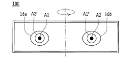
- FIG. 1B is a schematic view showing an outline of the image display device 100 according to the first embodiment, and is a front view of the image display device 100.
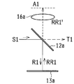
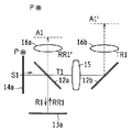
- FIG. 2A is a diagram for explaining the display of the image in the air, and is a top view for explaining the light path of the first image A1.
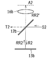
- FIG. 2B is a view for explaining the display of the image in the air, and is a top view for explaining the light path of the second image A2.
- FIG. 2C is a diagram for explaining the display of the image in the air, and is a front view showing how the first image A1 is viewed.
- FIG. 1A is a schematic view showing an outline of the image display device 100 according to the first embodiment, and is a top view of the image display device 100.
- FIG. 1B is a schematic view showing an outline of the image display device 100 according to the first embodiment
- FIG. 2D is a diagram for explaining the display of the image in the air, and is a front view showing how the second image A2 looks.
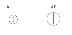
- FIG. 3A is a diagram for explaining the display of an image in the air by the transmitted lights T1 and T2 transmitted through the beam splitters 12a and 12b, and is a top view for explaining the light path of the images A1 and A1'.
- FIG. 3B is a diagram for explaining the display of an image in the air by the transmitted lights T1 and T2 transmitted through the beam splitters 12a and 12b, and is a top view for explaining the light path of the images A2 and A2'.
- FIG. 3A is a diagram for explaining the display of an image in the air by the transmitted lights T1 and T2 transmitted through the beam splitters 12a and 12b, and is a top view for explaining the light path of the images A2 and A2'.
- FIG. 3C is a diagram for explaining the display of an image in the air by the transmitted lights T1 and T2 transmitted through the beam splitters 12a and 12b, and is a front view showing how the images A1 and A1'appear.
- FIG. 3D is a diagram for explaining the display of an image in the air by the transmitted lights T1 and T2 transmitted through the beam splitters 12a and 12b, and is a front view showing how the images A2 and A2'appear.
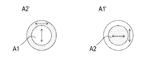
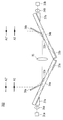
- FIG. 4 is a diagram schematically showing the overlap of the images A1 and A2'on the right eye side and the overlap of the images A2 and A1'on the left eye side.
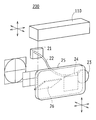
- FIG. 5A is a perspective view schematically showing an outline of the image display device 200 according to the second embodiment, and is an example in which the dielectric multilayer film reflector 26 is arranged farther from the light guide plate portion 25.
- FIG. 5B is a perspective view schematically showing an outline of the image display device 200 according to the second embodiment, and is an example in which the dielectric multilayer film reflector 26 is arranged in front of the light guide plate portion 25.
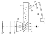
- FIG. 6A is a top view schematically showing the projection of the image in the example shown in FIG. 5A.
- FIG. 6B is a side view schematically showing the projection of the image in the example shown in FIG. 5A.
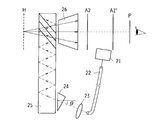
- FIG. 7A is a top view schematically showing the projection of the image in the example shown in FIG. 5B.
- FIG. 7B is a side view schematically showing the projection of the image in the example shown in FIG. 5B.
- FIG. 8 is a schematic view showing an outline of the image display device 300 according to the third embodiment.
- FIGS. 1A and 1B are schematic views showing an outline of the image display device 100 according to the present embodiment
- FIG. 1A is a top view
- FIG. 1B is a front view
- the image display device 100 includes image projection units 11a and 11b, beam splitters 12a and 12b, retroreflective units 13a and 13b, polarizers 14a and 14b, and a cylindrical lens 15.
- the imaging lenses 16a and 16b are provided.
- the image projection units 11a and 11b are devices that irradiate the light that constitutes the image (first image, second image), and project images for the right eye and the left eye, respectively.
- the image projection units 11a and 11b have opposite light irradiation directions and are arranged so as to face each other.
- the configuration of the image projection units 11a and 11b is not limited, and a liquid crystal display device provided with a backlight, a self-luminous organic EL display device, a projector device using a light source and a modulation element, and the like may be used.
- the images projected by the image projection units 11a and 11b may be still images or moving images.
- the images projected by both the image projection units 11a and 11b may be the same or different.
- the beam splitters 12a and 12b are members that transmit a part of the incident light and reflect the other part of the incident light.
- the beam splitters 12a and 12b may be partial reflectors in which a film for adjusting the reflectance is formed on the surface of the transparent plate.
- the light transmittance and the reflectance of the beam splitters 12a and 12b may be set in any balance. In the present embodiment, for example, the transmittance is 50% and the reflectance is 50%.
- the beam splitters 12a and 12b are arranged so as to be at an angle of 45 degrees with respect to the optical axis of the light emitted from the image projection units 11a and 11b, and are arranged orthogonal to each other.
- the beam splitters 12a and 12b are tilted at an angle of 45 degrees, and the beam splitters 12a and 12b are orthogonal to each other.
- the direction of light irradiation from the image projection units 11a and 11b and the image formation position of the image are shown.
- the beam splitters 12a and 12b may be arranged at an appropriate angle in relation to the above.
- the retroreflective parts 13a and 13b are optical members that reflect the incident light in the direction opposite to the incident direction while maintaining the light collecting property.
- the retroreflective portions 13a and 13b may be retroreflective plates having a structure in which minute glass beads are spread on the surface side of the reflective film or a prism.
- the retroreflective portions 13a and 13b may be separate retroreflective plates, or may share one retroreflective plate.
- the polarizers 14a and 14b are polarizing plates that are arranged between the image projection units 11a and 11b and the beam splitters 12a and 12b, respectively, and determine the polarization direction of the light emitted from the image projection units 11a and 11b.
- the polarization directions of the polarizer 14a and the polarizer 14b are orthogonal to each other.
- the polarizer 14a polarizes the light in the direction perpendicular to the drawing
- the polarizer 14b polarizes the light in the vertical direction in the drawing.
- the cylindrical lens 15 is an optical member that transmits light incident from one surface and condenses it on the other side. As shown in FIGS. 1A and 1B, the cylindrical lens 15 is arranged in the center of the image display device 100 perpendicular to the optical axis of the light emitted from the image projection units 11a and 11b.
- the imaging lenses 16a and 16b are optical members for forming an image of light incident from the beam splitters 12a and 12b at a predetermined position in space, and correspond to the imaging optical unit in the present disclosure.
- the solid lines drawn from the image projection units 11a and 11b to the beam splitters 12a and 12b indicate the path of the projected light of the image irradiated by the image projection units 11a and 11b.
- the solid lines drawn from the beam splitters 12a and 12b to the retroreflective portions 13a and 13b indicate the paths of the reflected light reflected by the beam splitters 12a and 12b and the retroreflective light reflected by the retroreflective portions 13a and 13b. ..
- the solid line passing through the imaging lenses 16a and 16b from the beam splitters 12a and 12b indicates the path of transmitted retrolight transmitted through the beam splitters 12a and 12b.
- the broken lines from the beam splitters 12a and 12b to the beam splitters 12b and 12a on the opposite side via the cylindrical lens 15 indicate the path of transmitted light transmitted through the beam splitters 12a and 12b, respectively.
- the broken lines passing from the beam splitters 12a and 12b through the imaging lenses 16a and 16b indicate the path of the transmitted reflected light reflected by the beam splitters 12a and 12b.
- the projected light emitted from the image projection units 11a and 11b travels as reflected light, retrolight, transmitted light, transmitted retrolight, and transmitted reflected light, and travels at a predetermined position in space. Is imaged as images A1, A2, A1', A2'. In the examples shown in FIGS. 1A and 1B, the images A1 and A2'are superimposed and displayed on the right eye side, and the images A2 and A1'are superimposed and displayed on the left eye side.
- FIGS. 1A and 1B are diagrams for explaining the display of an image in the air.
- FIG. 2A is a top view illustrating the path of light in image A1.
- FIG. 2B is a top view illustrating the path of light in image A2.
- FIG. 2C is a front view showing how the image A1 looks.
- FIG. 2D is a front view showing how the image A2 looks.
- the optical path is shown including the spread of light, but in FIGS. 2A to 2D, the traveling direction is indicated only by lines and arrows for simplification. Further, the members not necessary for the explanation of the optical path are not shown and explained.
- the projected light S1 (first projection light) emitted from the image projection unit 11a (first image projection unit) travels toward the beam splitter 12a (first beam splitter) and is beamed. It is incident on one surface of the splitter 12a. A part of the projected light S1 is reflected by the beam splitter 12a and travels toward the retroreflective portion 13a (first retroreflective portion) as reflected light R1 (first reflected light), and the other part of the projected light S1 is It passes through the beam splitter 12a and travels in the extension direction of the projected light S1 as the transmitted light T1 (first transmitted light).
- the reflected light R1 that has reached the retroreflective portion 13a as the first retroreflective light is reflected by the retroreflective portion 13a in the direction opposite to the incident direction.
- the retroreflected light RR1 reaches the beam splitter 12a again, passes through the beam splitter 12a, and is imaged as an image A1 in space through the imaging lens 16a (first imaging optical unit) as transmitted retrolight RR1'.
- the reflected light R1 (first reflected light) reflected by the beam splitter 12a travels toward the retroreflective portion 13a (first retroreflective portion), but the traveling direction of the reflected light R1 is retrograde.
- the direction toward the reflecting portion 13a is not limited.
- Another optical member may be arranged between the beam splitter 12a and the retroreflective portion 13a, and the reflected light R1 may finally reach the retroreflective portion 13a.
- the projection light S2 (second projection light) emitted from the image projection unit 11b (second image projection unit) travels toward the beam splitter 12b (second beam splitter).
- the beam splitter 12b (second beam splitter).
- a part of the projected light S2 is reflected by the beam splitter 12b and travels toward the retroreflective part 13b (second retroreflective part) as reflected light R2 (second reflected light)
- the other part of the projected light S2 is It passes through the beam splitter 12b and travels in the extension direction of the projected light S2 as transmitted light T2 (second transmitted light).
- the reflected light R2 that has reached the retroreflective unit 13b as the second retroreflective light is reflected by the retroreflective unit 13b as the retroreflective light RR2 in the direction opposite to the incident direction.
- the retroreflected light RR2 reaches the beam splitter 12b again, passes through the beam splitter 12b, and is imaged as an image A2 in space through the imaging lens 16b (second imaging optical unit) as transmitted retrolight RR2'.
- the image A1 is formed on the right eye side by the projected light S1 emitted from the image projection unit 11a, and the image A1 is formed on the left eye side by the projected light S2 emitted from the image projection unit 11b.
- Image A2 is imaged.
- the imaging lenses 16a and 16b are not arranged, and the projected light S1, S2, the reflected light R1, R2, the retrospective light RR1, RR2, and the transmitted retrospective light RR1', RR2 until the images A1 and A2 are imaged.
- the members are arranged so that the optical path lengths of ‘’ are equal, the images A1 and A2 are visually recognized at the same position in the air on the right eye side and the left eye side.
- the emission positions of the projected lights S1 and S2 are moved in the vertical direction in the figure so that the optical path lengths are different, the images A1 and A2 are visually recognized at different positions in the air on the right eye side and the left eye side. Further, by moving the positions of the imaging lenses 16a and 16b in the vertical direction in the drawing, the images A1 and A2 are visually recognized at different positions in the air on the right eye side and the left eye side.
- FIG. 3A, 3B, 3C and 3D are diagrams for explaining the display of an image in the air by the transmitted lights T1 and T2 transmitted through the beam splitters 12a and 12b.
- FIG. 3A is a top view illustrating the light path of the images A1 and A1'.
- FIG. 3B is a top view illustrating the light path of the images A2 and A2'.
- FIG. 3C is a front view showing how the images A1 and A1'appear.
- FIG. 3D is a front view showing how the images A2 and A2'appear.
- the transmitted light T1 transmitted through the beam splitter 12a is incident on the beam splitter 12b via the cylindrical lens 15 as the transmitted reflected light TR1. Be reflected.
- the transmitted reflected light TR1 is imaged as an image A1'in space through the imaging lens 16b.
- the polarizing element 14a first polarizer
- the image A1' is imaged through the cylindrical lens 15 and the optical path length from the image projection unit 11a is different, the images A1 and A1' are visually recognized at different depths on the right eye side and the left eye side. Will be done.
- the images A1 and A1' are both irradiated from the image projection unit 11a, the display contents are the same, and the image itself is inverted.
- the transmitted light T2 transmitted through the beam splitter 12b is incident on the beam splitter 12a via the cylindrical lens 15 and reflected by transmission. It is reflected as light TR2.
- the transmitted reflected light TR2 is imaged as an image A2'in space through the imaging lens 16a.
- the polarizing element 14b second polarizer
- the polarization directions of the polarizers 14a and 14b are orthogonal to each other, the polarization directions of the images A1 and A1'and the images A2 and A2'are also orthogonal to each other.
- the image A2' is displayed through the cylindrical lens 15 and the optical path length from the image projection unit 11b is different, the images A2' and A2 are visually recognized at different depths on the right eye side and the left eye side. To.
- FIG. 4 is a diagram schematically showing the overlap of the images A1 and A2'on the right eye side and the overlap of the images A2 and A1'on the left eye side.
- the polarizers 14a and 14b shown in FIGS. 3A to 3D on the right eye side, the image A1 polarized in the vertical direction in the figure and the A2'polarized in the horizontal direction in the figure can be visually recognized overlapping at different depths.
- the image A2 polarized in the left-right direction in the figure and the image A1'polarized in the vertical direction in the figure can be visually recognized by overlapping at different depths.
- the polarizers 14a and 14b are a mechanism for switching the polarization direction, and another polarizer is arranged in front of the user's eyes, so that the images A1 and A2'and the images A2 and A1' are selectively selected. Can be displayed. Further, since light having different polarization directions can be blocked, noise light can be removed and noise of an image formed in the air can be removed.
- 1A, 1B, and 3A to 3D show an example in which images A1, A2', A2, and A1'are displayed on the right eye side and the left eye side, but one of the imaging lenses 16a and 16b is used.
- a light-shielding plate or the like may be arranged so that the two images are superimposed only on the other eye side.
- the cylindrical lens 15 may be combined with a reflector to reflect the transmitted light T1 or T2 in the direction of the cylindrical lens 15 again to form an image of images A1, A1'or A2, A2'on one eye side. ..
- the projected lights S1 and S2 are separated into the reflected lights R1 and R2 and the transmitted lights T1 and T2 by the beam splitters 12a and 12b, and the reflected lights R1 and R2 are the retrolight RR1.
- RR2 and images are formed by the imaging lenses 16a and 16b, so that the images A1 and A2 can be displayed at different positions from the images A1'and A2', and a plurality of images can be displayed in the depth direction. Is possible.
- FIGS. 5A to 7B are perspective views schematically showing an outline of the image display device 200 according to the present embodiment.
- FIG. 5A is an example in which the dielectric multilayer film reflector 26 is arranged farther from the light guide plate portion 25.
- FIG. 5B is an example in which the dielectric multilayer film reflector 26 is arranged in front of the light guide plate portion 25.
- the image display device 200 of the present embodiment includes a unit drive unit 110, a light source unit 21 (third light source unit), a fiber unit 22, a lens 23, a prism 24, and a director.
- a light plate portion 25 (waveguide portion) and a dielectric multilayer film reflector 26 are provided.
- the unit drive unit 110 is a device including a projection unit provided with a light source and an optical system for displaying an image in space, and a driving means for moving the projection unit three-dimensionally.
- the structure of the unit drive unit 110 is not limited, but for example, the image display device 100 shown in the first embodiment may be used as a projection unit by accommodating a drive means such as a motor in a housing.
- the unit drive unit 110 is arranged above the light guide plate unit 25 and the dielectric multilayer film reflector 26, and irradiates the dielectric multilayer film reflector 26 with light. It is composed.
- the light source unit 21 is a member that includes a semiconductor laser element and a package and emits light having a predetermined wavelength.
- the light source unit 21 projects an image (third image).
- the specific configuration of the light source unit 21 is not limited, and a known CAN type or frame type package may be used.
- a SHG (Second Harmonic Generation) element or the like may be mounted on the light source unit 21 for wavelength conversion.
- the wavelength of the light emitted by the light source unit 21 may be the same or different.
- the fiber unit 22 is an optical element that guides the light (third projected light) emitted from the light source unit 21, and is composed of a flexible optical fiber.
- the incident end face of the fiber portion 22 is arranged to face the light source portion 21, and the exit end face of the fiber portion 22 is arranged to face the lens 23.
- the lens 23 is an optical element for adjusting the spreading angle of the light emitted from the fiber portion 22 so that the light is incident on the light incident portion of the prism 24 and the light guide plate portion 25.
- a collimator lens may be used as the lens 23.
- the prism 24 is an optical element having a triangular cross section and is arranged in the vicinity of the light incident portion in which light is incident in the light guide plate portion 25. A gap is provided between the light guide plate portion 25 and the prism 24.
- the material constituting the prism 24 is not limited, but in order for the light from the light source unit 21 to be efficiently incident on the light guide plate portion 25, the refractive index of the prism 24 and the refractive index of the light guide plate portion 25 must be about the same. It is preferable that the prism 24 uses the same material as the light guide plate portion 25.
- the light guide plate portion 25 is a flat plate-shaped member made of a translucent material, and can see through from one surface side to the other surface side.
- a prism 24 is arranged close to the light incident portion on one end side of the light guide plate portion 25.
- the light guide plate portion 25 is formed with a light emitting portion such as a half mirror or a hologram inside on the opposite side of the prism 24. Therefore, in the light guide plate portion 25, the light traveling inside is emitted to the eyes of the user, and the light traveling from the side opposite to the user is transmitted.
- the dielectric multilayer film reflector 26 is a plate-shaped member having a multilayer film in which dielectrics having different refractive indexes are repeatedly laminated.
- the dielectric multilayer film reflector 26 is an optical member that reflects light of a predetermined wavelength depending on the thickness of the dielectric layer and transmits light of other wavelengths.
- the dielectric multilayer film reflector 26 is provided with a reflector drive unit that rotationally drives the angle of the reflection surface, and the reflector drive unit emits light in response to a control signal. It is possible to switch the reflection direction of.
- FIGS. 6A and 6B are diagrams schematically showing the projection of the image in the example shown in FIG. 5A.
- FIG. 6A is a top view and FIG. 6B is a side view.
- 7A and 7B are diagrams schematically showing the projection of an image in the example shown in FIG. 5B.
- FIG. 7A is a top view and FIG. 7B is a side view.
- FIGS. 6A and 6B show an example in which the angle of the dielectric multilayer film reflector 26 is controlled so that the images A1 and A2'are displayed farther from the light guide plate portion 25, and
- FIGS. 7A and 7B show images A2 and A2.
- An example is shown in which the angle of the dielectric multilayer film reflector 26 is controlled so that A1'is displayed in front of the light guide plate portion 25.
- the light emitted by the light source unit 21 is incident on the incident end surface of the fiber unit 22 and causes the lens 23 and the prism 24 from the emitted end surface of the fiber unit 22. It is incident on the light guide plate portion 25 via the light guide plate portion 25. Inside the light guide plate 25, light is repeatedly reflected to reach the light emitting portion, is irradiated to the user side (projection direction) as emitted light, displayed as an image H in the air, and transmitted through the light guide plate 25. It is visually recognized by superimposing it on the background.
- FIGS. 6B and 7B light is emitted from the unit drive unit 110 toward the dielectric multilayer film reflector 26 located below the unit drive unit 110, and the inclination angle of the dielectric multilayer film reflector 26 is adjusted. Light is emitted in the corresponding direction to display images A1, A2'and images A2, A1'.
- the image display device 100 of the first embodiment is used as the projection unit housed in the unit drive unit 110, the display positions of the images A1 and A2'and the images A2 and A1'in the air are shown in FIG. 1A. And, it corresponds to the optical path length described with reference to FIG. 1B. Therefore, the image H projected from the light source unit 21 and the images A1 and A2'and the images A2 and A1'displayed by the unit drive unit 110 are superimposed and displayed at positions having different depths.
- the polarizing element P that selects the polarization direction of the light transmitted in front of the user's eyes, the images A1 and A2'imaged in the air. It is possible to select which of the images A2 and A1'is to be visually recognized by the user.
- 6A, 6B, 7A and 7B show examples corresponding to the examples of the right eye side and the left eye side, respectively, but either the right eye side or the left eye side may be used.
- the imaging positions of the images A1, A2, A1'and A2' can be switched by switching the inclination angle. it can.
- the image H projected by the light source unit 21 and the images A1, A2, A1', A2'projected from the unit drive unit 110 are superimposed, and a plurality of images are superimposed in the depth direction. It is possible to form an image of. It is also possible to change the imaging positions of A1, A2, A1'and A2' formed in space.
- FIG. 8 is a schematic view showing an outline of the image display device 300 according to the present embodiment.
- the image display device 300 includes image projection units 31a and 31b, beam splitters 32a and 32b, retroreflective units 33a and 33b, light guide plate units 34a and 34b, a cylindrical lens 35, and a lens 36a. , 36b, prisms 37a, 37b, and mirrors 38a, 38b.
- the projected light emitted from the image projection units 31a and 31b is incident on the light guide plate portions 34a and 34b via the lenses 36a and 36 and the prisms 37a and 37b.
- the beam splitters 32a and 32b Inside the light guide plate portions 34a and 34b, light is repeatedly reflected and incident on the beam splitters 32a and 32b, and a part of the light is reflected by the beam splitters 32a and 32b to enter the light guide plate portions 34a and 34b. It travels toward 33b, and a part of it passes through the beam splitter 32a and travels toward the cylindrical lens 35.
- the light that reaches the retroreflective portions 33a and 33b is reflected in the direction opposite to the incident direction, is incident on the beam splitters 32a and 32b again and is transmitted, and then is reflected by the mirrors 38a and 38b to form images A1 and A2. Will be done.
- the light that has passed through the beam splitters 32a and 32b and reached the cylindrical lens 35 is reflected by the mirrors 38b and 38a on the opposite side and imaged as images A2'and A1'.
- the projected light is separated into reflected light and transmitted light by the beam splitters 32a and 32b, and the reflected light is imaged as retrolight. Therefore, the image display device 300 displays images A1 and A2 as images A1. It can be displayed at a position different from', A2', and a plurality of images can be imaged in the depth direction. By using the repeated reflection inside the light guide plate portions 34a and 34b, it is possible to reduce the thickness and weight of the image display device 300.
Landscapes
- Physics & Mathematics (AREA)
- General Physics & Mathematics (AREA)
- Optics & Photonics (AREA)
- Engineering & Computer Science (AREA)
- Multimedia (AREA)
- Signal Processing (AREA)
- Testing, Inspecting, Measuring Of Stereoscopic Televisions And Televisions (AREA)
Abstract
第1画像(A1)を投影する第1画像投影部(11a)と、第1画像投影部(11a)から照射された第1投影光を第1透過光および第1反射光に分離する第1ビームスプリッタ(12a)と、第1反射光を、第1ビームスプリッタ(12a)に第1再帰光として入射させる第1再帰反射部(13a)と、第1ビームスプリッタ(12a)を透過した第1再帰光を結像する第1結像光学部(16a)を有する画像表示装置(100)。
Description
本開示は、画像表示装置に関し、特に空中に画像を表示させる画像表示装置に関する。
従来から、車両内に各種情報を表示する装置として、アイコンを点灯表示する計器盤が用いられている。表示する情報量の増加に伴い、計器盤に画像表示装置が埋め込まれることや、計器盤全体が画像表示装置で構成されることもある。
計器盤は車両のフロントガラスより下方に位置している。運転者は、計器盤に表示された情報を視認する際、運転中に視線を下方に移動させる必要があり、好ましくない。そこで、運転者が車両の前方を視認したときに情報を読み取れるようにフロントガラスに画像を投影するヘッドアップディスプレイ(以下HUD:Head Up Display)が提案されている(例えば、特許文献1を参照)。このようなHUDでは、フロントガラスの広い範囲に画像を投影する光学装置が必要であり、光学装置の小型化および軽量化が望まれている。
小型の光学装置を用いて光を投影する画像表示装置としては、メガネ形状のヘッドマウント型のHUDが知られている(例えば、特許文献2を参照)。ヘッドマウント型のHUDは、光源から照射された光を利用者の眼に直接照射して、利用者の網膜に画像を投影する。
しかし、従来のヘッドマウント型HUDでは、視野内において画像の表示位置が限定されており、多様な情報を領域ごとに表示することは困難であった。また、視認される画像の距離も固定されていた。奥行方向に複数の画像を表示させることや、空中に視認される画像の表示位置を変化させるような複雑な表示ができなかった。
そこで本開示は、上記従来の問題点に鑑みなされたものであり、奥行方向に複数の画像を表示可能な画像表示装置を提供することを目的とする。
上記課題を解決するために、本開示の画像表示装置は、第1画像を投影する第1画像投影部と、前記第1画像投影部から照射された第1投影光を第1透過光および第1反射光に分離する第1ビームスプリッタと、前記第1反射光を、前記第1ビームスプリッタに第1再帰光として入射させる第1再帰反射部と、前記第1ビームスプリッタを透過した前記第1再帰光を結像する第1結像光学部を有する。
このような本開示の画像表示装置では、第1投影光が第1ビームスプリッタによって第1反射光と第1透過光に分離され、第1反射光は第1再帰光となって第1結像光学部で結像されるため、第1透過光とは異なる位置に結像することができ、奥行方向に複数の画像を表示することが可能となる。
また本開示の一態様では、第2画像を投影する第2画像投影部と、前記第2画像投影部から照射された第2投影光を第2透過光および第2反射光に分離する第2ビームスプリッタと、前記第2反射光を、前記第2ビームスプリッタに第2再帰光として入射させる第2再帰反射部と、前記第2ビームスプリッタを透過した前記第2再帰光を結像する第2結像光学部を有する。
また本開示の一態様では、前記第2ビームスプリッタは前記第1透過光を前記第2結像光学部に向けて反射し、前記第1ビームスプリッタは前記第2透過光を前記第1結像光学部に向けて反射する。
また本開示の一態様では、前記第1ビームスプリッタと前記第2ビームスプリッタの間にシリンドリカルレンズを備え、前記シリンドリカルレンズは前記第1透過光および前記第2透過光を透過させる。
また本開示の一態様では、前記第1投影光を第1方向に偏光させる第1偏光子と、前記第2投影光を前記第1方向に直交する第2方向に偏光させる第2偏光子を備える。
また本開示の一態様では、第3画像を投影する第3光源部と、前記第3光源部から照射された第3投影光を導波する導波部と、前記第3投影光を前記導波部の外に照射する光出射部と、前記第1結像光学部を経由した光を反射する誘電体多層膜反射板を備え、前記再帰光が結像する位置と、前記第3投影光が結像する位置とが異なっている。
また本開示の一態様では、前記誘電体多層膜反射板を回転駆動する反射板駆動部を備える。
また本開示の一態様では、前記第1結像光学部と前記誘電体多層膜反射板の相対位置を変化させるユニット駆動部を備える。
本開示では、奥行方向に複数の画像を表示可能な画像表示装置を提供することができる。
(第1実施形態)
以下、本開示の実施の形態について、図面を参照して詳細に説明する。各図面に示される同一または同等の構成要素、部材、処理には、同一の符号を付すものとし、適宜重複した説明は省略する。図1A及び図1Bは、本実施形態に係る画像表示装置100の概略を示す模式図であり、図1Aは上面図であり、図1Bは正面図である。図1A及び図1Bに示すように、画像表示装置100は、画像投影部11a,11bと、ビームスプリッタ12a,12bと、再帰反射部13a,13bと、偏光子14a,14bと、シリンドリカルレンズ15と、結像レンズ16a,16bを備えている。
以下、本開示の実施の形態について、図面を参照して詳細に説明する。各図面に示される同一または同等の構成要素、部材、処理には、同一の符号を付すものとし、適宜重複した説明は省略する。図1A及び図1Bは、本実施形態に係る画像表示装置100の概略を示す模式図であり、図1Aは上面図であり、図1Bは正面図である。図1A及び図1Bに示すように、画像表示装置100は、画像投影部11a,11bと、ビームスプリッタ12a,12bと、再帰反射部13a,13bと、偏光子14a,14bと、シリンドリカルレンズ15と、結像レンズ16a,16bを備えている。
画像投影部11a,11bは、画像(第1画像,第2画像)を構成する光を照射する装置であり、それぞれ右目用と左目用の画像を投影する。図1A及び図1Bでは、画像投影部11a,11bはそれぞれ光の照射方向が反対であり、互いに対向して配置されている。画像投影部11a,11bの構成は限定されず、バックライトを備えた液晶表示装置、自発光の有機EL表示装置、光源と変調素子を用いたプロジェクター装置等を用いてもよい。画像投影部11a,11bが投影する画像は、静止画でも動画であってもよい。画像投影部11a,11bの両者の投影する画像が同一であっても異なっていてもよい。
ビームスプリッタ12a,12bは、入射した光の一部を透過するとともに、入射した光の他の一部を反射する部材である。ビームスプリッタ12a,12bは、透明板の表面に反射率を調整する膜が形成された部分反射板でもよい。ビームスプリッタ12a,12bでの光の透過率と反射率は任意のバランスで設定されてよい。本実施形態においては例えば透過率を50%として反射率を50%とする。ビームスプリッタ12a,12bは各々が画像投影部11a,11bから照射される光の光軸に対して45度の角度となるように配置されるとともに、互いに直交して配置されている。本実施形態ではビームスプリッタ12a,12bの傾斜角度が45度であり、ビームスプリッタ12a,12bが互いに直交する例を示したが、画像投影部11a,11bからの光照射方向と画像の結像位置との関係から適切な角度でビームスプリッタ12a,12bは配置されてもよい。
再帰反射部13a,13bは、入射した光を入射方向の反対方向へ集光性を保ったまま反射させる光学部材である。再帰反射部13a,13bは、反射膜の表面側に微小なガラスビーズを敷き詰めた構造やプリズムを有する再帰反射板でもよい。再帰反射部13a,13bは、それぞれ別体の再帰反射板でもよく、一枚の再帰反射板を共有してもよい。
偏光子14a,14bは、それぞれ画像投影部11a,11bとビームスプリッタ12a,12bの間に配置され、画像投影部11a,11bから照射された光の偏光方向を決定する偏光板である。偏光子14aと偏光子14bの偏光方向はそれぞれ直交し、例えば偏光子14aは光を図面に垂直方向に偏光させ、偏光子14bは光を図中上下方向に偏光させる。
シリンドリカルレンズ15は、一方の面から入射した光を透過して反対側で集光させる光学部材である。図1A及び図1Bに示したように、シリンドリカルレンズ15は画像表示装置100の中央において、画像投影部11a,11bから照射される光の光軸に垂直に配置されている。
結像レンズ16a,16bは、ビームスプリッタ12a,12bから入射した光を空間上の所定位置に結像させるための光学部材であり、本開示における結像光学部に相当している。
図1Aにおいて、画像投影部11a,11bからビームスプリッタ12a,12bまで描かれた実線は、画像投影部11a,11bが照射する画像の投影光の経路を示している。ビームスプリッタ12a,12bから再帰反射部13a,13bまで描かれた実線は、ビームスプリッタ12a,12bで反射された反射光と、再帰反射部13a,13bで反射された再帰光の経路を示している。ビームスプリッタ12a,12bから結像レンズ16a,16bを通過している実線は、ビームスプリッタ12a,12bを透過した透過再帰光の経路を示している。
それぞれビームスプリッタ12a,12bからシリンドリカルレンズ15を経由して反対側のビームスプリッタ12b,12aまで至る破線は、ビームスプリッタ12a,12bを透過した透過光の経路を示している。ビームスプリッタ12a,12bから結像レンズ16a,16bを通過している破線は、ビームスプリッタ12a,12bによって反射された透過反射光の経路を示している。
図1A及び図1Bに示したように、画像投影部11a,11bから照射された投影光は、反射光、再帰光、透過光、透過再帰光、透過反射光として進行し、空間上の所定位置に画像A1,A2,A1’,A2’として結像される。図1A及び図1Bに示した例では、右目側に画像A1とA2’が重ね合わされて表示され、左目側に画像A2とA1’が重ね合わされて表示される。
図2A,図2B,図2C,図2Dは、空中への画像の表示を説明する図である。図2Aは画像A1の光の経路を説明する上面図である。図2Bは画像A2の光の経路を説明する上面図である。図2Cは画像A1の見え方を示す正面図である。図2Dは画像A2の見え方を示す正面図である。図1A及び図1Bでは光の拡がりを含めて光路を示したが、図2Aから図2Dでは簡略化のため進行方向を線と矢印のみで表している。また、光路の説明に不要な部材は図示と説明を省略している。
図2Aに示すように、画像投影部11a(第1画像投影部)から照射された投影光S1(第1投影光)は、ビームスプリッタ12a(第1ビームスプリッタ)に向かって進行して、ビームスプリッタ12aの一方の面に入射する。投影光S1の一部はビームスプリッタ12aで反射されて反射光R1(第1反射光)として再帰反射部13a(第1再帰反射部)に向かって進行し、投影光S1の他の一部はビームスプリッタ12aを透過して透過光T1(第1透過光)として投影光S1の延長方向に進行する。第1再帰光として再帰反射部13aに到達した反射光R1は、再帰反射部13aにより入射方向と反対方向に反射される。再帰反射光RR1は再度ビームスプリッタ12aに到達した後にビームスプリッタ12aを透過して、透過再帰光RR1’として結像レンズ16a(第1結像光学部)を経て空間中に画像A1として結像される。なお本実施形態では、ビームスプリッタ12aで反射された反射光R1(第1反射光)は、再帰反射部13a(第1再帰反射部)に向かって進行するが、反射光R1の進行方向は再帰反射部13aに向かう方向に限定されない。ビームスプリッタ12aと再帰反射部13aの間に他の光学部材が配置されてもよく、反射光R1が最終的に再帰反射部13aに到達すればよい。
同様に図2Bに示すように、画像投影部11b(第2画像投影部)から照射された投影光S2(第2投影光)は、ビームスプリッタ12b(第2ビームスプリッタ)に向かって進行して、ビームスプリッタ12bの一方の面に入射する。投影光S2の一部はビームスプリッタ12bで反射されて反射光R2(第2反射光)として再帰反射部13b(第2再帰反射部)に向かって進行し、投影光S2の他の一部はビームスプリッタ12bを透過して透過光T2(第2透過光)として投影光S2の延長方向に進行する。第2再帰光として再帰反射部13bに到達した反射光R2は、再帰反射部13bにより再帰反射光RR2として入射方向と反対方向に反射される。再帰反射光RR2は再度ビームスプリッタ12bに到達した後にビームスプリッタ12bを透過して、透過再帰光RR2’として結像レンズ16b(第2結像光学部)を経て空間中に画像A2として結像される。
図2C及び図2Dに示したように、画像投影部11aから照射された投影光S1によって右目側には画像A1が結像され、画像投影部11bから照射された投影光S2によって左目側には画像A2が結像される。ここで、結像レンズ16a,16bは配置されず、画像A1,A2が結像されるまでの投影光S1,S2、反射光R1,R2、再帰光RR1,RR2、透過再帰光RR1’,RR2’の光路長が等しくなるように各部材が配置されると、画像A1,A2は右目側と左目側で空中の同じ位置に視認される。逆に、光路長が異なるように投影光S1,S2の出射位置を図中上下方向に動かすと、画像A1,A2は右目側と左目側で空中の異なる位置に視認される。さらに、結像レンズ16a,16bの位置を図中上下方向に動かすことによっても、画像A1,A2は右目側と左目側で空中の異なる位置に視認される。
図3A、図3B、図3C及び図3Dは、ビームスプリッタ12a,12bを透過した透過光T1,T2による空中への画像の表示を説明する図である。図3Aは画像A1とA1’の光の経路を説明する上面図である。図3Bは画像A2とA2’の光の経路を説明する上面図である。図3Cは画像A1とA1’の見え方を示す正面図である。図3Dは画像A2とA2’の見え方を示す正面図である。
図3Aに示すように、画像投影部11aから照射された投影光S1のうち、ビームスプリッタ12aを透過した透過光T1は、シリンドリカルレンズ15を介してビームスプリッタ12bに入射して透過反射光TR1として反射される。透過反射光TR1は、結像レンズ16bを経て空間中に画像A1’として結像される。このとき、画像投影部11aとビームスプリッタ12aとの間に偏光子14a(第1偏光子)が配置されることで、画像A1とA1’の偏光方向(第1方向)が同一となる。また、シリンドリカルレンズ15を介して画像A1’が結像されること、および画像投影部11aからの光路長が異なっていることから、右目側と左目側で異なる奥行きに画像A1とA1’が視認される。画像A1とA1’は、いずれも画像投影部11aから照射されたものであり、表示内容は同一で、イメージ自体は反転する。
同様に、図3Bに示すように、画像投影部11bから照射された投影光S2のうち、ビームスプリッタ12bを透過した透過光T2は、シリンドリカルレンズ15を介してビームスプリッタ12aに入射して透過反射光TR2として反射される。透過反射光TR2は、結像レンズ16aを経て空間中に画像A2’として結像される。このとき、画像投影部11bとビームスプリッタ12bとの間に偏光子14b(第2偏光子)が配置されることで、画像A2とA2’の偏光方向(第2方向)が同一となる。また、偏光子14aと14bの偏光方向は互いに直交しているので、画像A1,A1’と画像A2,A2’の偏光方向も互いに直交している。また、シリンドリカルレンズ15を介して画像A2’が表示されること、および画像投影部11bからの光路長が異なっていることから、右目側と左目側で異なる奥行きに画像A2’とA2が視認される。画像A2とA2’は、いずれも画像投影部11bから照射されたものであり、表示内容は同一で、イメージ自体は反転する。
図4は、右目側での画像A1とA2’の重なりと、左目側での画像A2とA1’の重なりを模式的に示す図である。図3Aから図3Dに示した偏光子14a,14bの例においては、右目側では図中上下方向に偏光した画像A1と図中左右方向に偏光したA2’が異なる奥行きで重なり合って視認できる。また、左目側では図中左右方向に偏光した画像A2と図中上下方向に偏光したA1’が異なる奥行きで重なり合って視認できる。
これにより、偏光子14a,14bが偏光方向の切り替え機構であり、利用者の眼前にも別の偏光子が配置されることで、画像A1,A2’と画像,A2,A1’の選択的な表示を行うことができる。また、偏光方向が異なる光を遮ることができるため、ノイズ光を除去して空中に結像された画像のノイズを除去することができる。
図1A, 図1Bおよび図3Aから図3Dでは、右目側と左目側に画像A1,A2’,A2,A1’を表示させた例を示したが、結像レンズ16a,16bのいずれか一方に遮光板等を配置して、他方の目側にだけ2つの画像を重ね合わせるとしてもよい。また、シリンドリカルレンズ15に反射板を組み合わせて、透過光T1またはT2を再度シリンドリカルレンズ15方向に反射して、片方の目側に画像A1,A1’またはA2,A2’を結像させるとしてもよい。
上述したように本実施形態の画像表示装置100では、投影光S1,S2がビームスプリッタ12a,12bによって反射光R1,R2と透過光T1,T2に分離され、反射光R1,R2は再帰光RR1,RR2となって結像レンズ16a,16bで結像されるため、画像A1,A2を画像A1’,A2’とは異なる位置に表示することができ、奥行方向に複数の画像を表示することが可能となる。
(第2実施形態)
次に、本開示の第2実施形態について図5A~図7Bを用いて説明する。第1実施形態と重複する内容は説明を省略する。図5A及び図5Bは、本実施形態に係る画像表示装置200の概略を模式的に示す斜視図である。図5Aは誘電体多層膜反射板26を導光板部25より遠方に配置した例である。図5Bは誘電体多層膜反射板26を導光板部25より手前に配置した例である。
次に、本開示の第2実施形態について図5A~図7Bを用いて説明する。第1実施形態と重複する内容は説明を省略する。図5A及び図5Bは、本実施形態に係る画像表示装置200の概略を模式的に示す斜視図である。図5Aは誘電体多層膜反射板26を導光板部25より遠方に配置した例である。図5Bは誘電体多層膜反射板26を導光板部25より手前に配置した例である。
図5A及ぶ図5Bに示すように本実施形態の画像表示装置200は、ユニット駆動部110と、光源部21(第3光源部)と、ファイバ部22と、レンズ23と、プリズム24と、導光板部25(導波部)と、誘電体多層膜反射板26を備えている。
ユニット駆動部110は、空間に画像を表示する光源や光学系を備えた投影ユニットと、投影ユニットを三次元的に移動させる駆動手段を備えた装置である。ユニット駆動部110の構造は限定されないが、例えば筐体内にモータ等の駆動手段を収容して投影ユニットとして第1実施形態で示した画像表示装置100を用いてもよい。ユニット駆動部110は、図5A及び図5Bに示したように導光板部25および誘電体多層膜反射板26の上方に配置されており、誘電体多層膜反射板26に対して光を照射する構成とされている。
光源部21は、半導体レーザ素子とパッケージを備えて、所定波長の光を出射する部材である。光源部21は画像(第3画像)を投影する。光源部21の具体的な構成は限定されず、公知のCAN型やフレーム型パッケージを用いてもよい。光源部21にはSHG(Second Harmonic Generation)素子等を搭載して波長変換するとしてもよい。光源部21が出射する光の波長は同一であってもよく、異なる波長であってもよい。
ファイバ部22は、光源部21から照射された光(第3投影光)を導波する光学要素であり、可撓性を有する光ファイバで構成されている。ファイバ部22の入射端面は光源部21に対向して配置され、ファイバ部22の出射端面はレンズ23に対向して配置されている。
レンズ23は、ファイバ部22から出射された光の拡がり角を調整して、プリズム24および導光板部25の光入射部に光を入射させるための光学要素である。レンズ23は、コリメータレンズを用いてもよい。
プリズム24は、導光板部25のうち光を入射する光入射部の近傍に配置され断面三角形状の光学要素である。導光板部25とプリズム24との間には間隙が設けられている。プリズム24を構成する材料は限定されないが、光源部21からの光を効率よく導光板部25に入射させるためには、プリズム24の屈折率と導光板部25の屈折率が同程度であることが好ましく、プリズム24は導光板部25と同じ材料を用いることが好ましい。
導光板部25は、透光性材料からなる平板状の部材であり、一方の面側から他方の面側を透視可能である。導光板部25の一端側にはプリズム24が光入射部に近接して配置されている。また導光板部25は、プリズム24と反対側内部にはハーフミラーやホログラム等の光出射部が形成されている。したがって導光板部25では、内部を進行してきた光を利用者の眼に対して出射するとともに、利用者とは反対側から進行してきた光は透過する。
誘電体多層膜反射板26は、屈折率の異なる誘電体を繰り返し積層した多層膜を有する板状の部材である。誘電体多層膜反射板26は、誘電体層の膜厚によって所定波長の光を反射し、その他の波長の光を透過する光学部材である。図5A及び図5Bでは図示していないが、誘電体多層膜反射板26には反射面の角度を回転駆動する反射板駆動部が取り付けられており、反射板駆動部は制御信号に応じて光の反射方向を切り替えることが可能である。
図6A及び図6Bは、図5Aに示した例における画像の投影を模式的に示す図である。図6Aは上面図であり、図6Bは側方図である。図7A及び図7Bは、図5Bに示した例における画像の投影を模式的に示す図である。図7Aは上面図であり、図7Bは側方図である。また、図6A及び図6Bでは画像A1,A2’を導光板部25より遠方に表示させるように誘電体多層膜反射板26の角度を制御した例を示し、図7A及び図7Bでは画像A2,A1’を導光板部25より手前に表示させるように誘電体多層膜反射板26の角度を制御した例を示している。
図6Aおよび図7Aに示すように、本実施形態の画像表示装置200では、光源部21が出射した光はファイバ部22の入射端面に入射されファイバ部22の出射端面からレンズ23およびプリズム24を介して導光板部25に入射する。導光板部25の内部では、光が繰り返し反射されて光出射部に到達し、利用者側(投影方向)に出射光として照射されて空中に画像Hとして表示され、導光板部25を透過してきた背景とを重ね合わせて視認される。
図6Bおよび図7Bに示すように、ユニット駆動部110からユニット駆動部110の下方に位置する誘電体多層膜反射板26に向けて光が照射され、誘電体多層膜反射板26の傾斜角度に対応した方向に光が照射されて画像A1,A2’および画像A2,A1’が表示される。ここで、ユニット駆動部110内に収容された投影ユニットとして第1実施形態の画像表示装置100を用いた場合には、空中における画像A1,A2’および画像A2,A1’の表示位置は図1A及び図1Bを用いて説明した光路長に対応したものとなる。したがって、光源部21から投影された画像Hと、ユニット駆動部110で表示された画像A1,A2’および画像A2,A1’は奥行きが異なる位置に重ね合わせて表示される。
ユニット駆動部110内において投影ユニット(画像表示装置100)の位置を三次元的に移動させると、照射される光の経路や光路長が変化するため、画像A1,A2’および画像A2,A1’が表示される位置も変化する。これにより、画像A1,A2’,A2,A1’の画像Hや背景中に対する相対位置を変化させて表示することも可能となる。
図6A、図6B、図7Aおよび図7Bに示したように、利用者の眼前に透過する光の偏光方向を選択する偏光子Pを配置することで、空中に結像した画像A1,A2’および画像A2,A1’の何れを利用者に視認させるかを選択することができる。
図6A、図6B、図7A及び図7Bではそれぞれ右目側と左目側の例に対応した例を示しているが、右目側と左目側どちらであってもよい。誘電体多層膜反射板26は導光板部25より遠方側と手前側のどちらに配置した場合でも、傾斜角度を切り替えることで画像A1,A2,A1’,A2’の結像位置を切り替えることができる。
上述したように本実施形態の画像表示装置200では、光源部21が投影する画像Hと、ユニット駆動部110から投影される画像A1,A2,A1’,A2’を重ね合わせ、奥行方向に複数の画像を結像することが可能となる。空間中に結像したA1,A2,A1’,A2’の結像位置を変化させることもできる。
(第3実施形態)
次に、本開示の第3実施形態について図8を用いて説明する。第1実施形態と重複する内容は説明を省略する。図8は、本実施形態に係る画像表示装置300の概略を示す模式図である。図8に示すように画像表示装置300は、画像投影部31a,31bと、ビームスプリッタ32a,32bと、再帰反射部33a,33bと、導光板部34a,34bと、シリンドリカルレンズ35と、レンズ36a,36bと、プリズム37a,37bと、ミラー38a,38bを備えている。
次に、本開示の第3実施形態について図8を用いて説明する。第1実施形態と重複する内容は説明を省略する。図8は、本実施形態に係る画像表示装置300の概略を示す模式図である。図8に示すように画像表示装置300は、画像投影部31a,31bと、ビームスプリッタ32a,32bと、再帰反射部33a,33bと、導光板部34a,34bと、シリンドリカルレンズ35と、レンズ36a,36bと、プリズム37a,37bと、ミラー38a,38bを備えている。
本実施形態の画像表示装置300では、画像投影部31a,31bから照射された投影光は、レンズ36a,36およびプリズム37a,37bを介して導光板部34a,34bに入射する。導光板部34a,34bの内部では、光が繰り返し反射されてビームスプリッタ32a,32bに入射し、一部はビームスプリッタ32a,32bで反射されて導光板部34a,34b内を再帰反射部33a,33bに向かって進行し、一部はビームスプリッタ32aを透過してシリンドリカルレンズ35に向かって進行する。再帰反射部33a,33bに到達した光は、入射方向と反対方向に反射されて再度ビームスプリッタ32a,32bに入射して透過した後に、ミラー38a,38bに反射されて画像A1,A2が結像される。
また、ビームスプリッタ32a,32bを透過してシリンドリカルレンズ35に到達した光は、反対側のミラー38b,38aによって反射されて画像A2’,A1’として結像される。
本実施形態でも、投影光がビームスプリッタ32a,32bによって反射光と透過光に分離され、反射光は再帰光となって結像されるため、の画像表示装置300は画像A1,A2を画像A1’,A2’とは異なる位置に表示することができ、奥行方向に複数の画像を結像することが可能となる。導光板部34a,34bの内部での繰り返し反射を用いることで、画像表示装置300の薄型化と軽量化を図ることができる。
本開示は上述した各実施形態に限定されるものではなく、請求項に示した範囲で種々の変更が可能であり、異なる実施形態にそれぞれ開示された技術的手段を適宜組み合わせて得られる実施形態についても本開示の技術的範囲に含まれる。
本出願は、2019年6月5日出願の日本出願第2019-105128号に基づく優先権を主張し、前記日本出願に記載された全ての記載内容を援用するものである。
Claims (8)
- 第1画像を投影する第1画像投影部と、
前記第1画像投影部から照射された第1投影光を第1透過光および第1反射光に分離する第1ビームスプリッタと、
前記第1反射光を、前記第1ビームスプリッタに第1再帰光として入射させる第1再帰反射部と、
前記第1ビームスプリッタを透過した前記第1再帰光を結像する第1結像光学部を有する画像表示装置。 - 請求項1に記載の画像表示装置であって、
第2画像を投影する第2画像投影部と、
前記第2画像投影部から照射された第2投影光を第2透過光および第2反射光に分離する第2ビームスプリッタと、
前記第2反射光を、前記第2ビームスプリッタに第2再帰光として入射させる第2再帰反射部と、
前記第2ビームスプリッタを透過した前記第2再帰光を結像する第2結像光学部を有する画像表示装置。 - 請求項2に記載の画像表示装置であって、
前記第2ビームスプリッタは前記第1透過光を前記第2結像光学部に向けて反射し、
前記第1ビームスプリッタは前記第2透過光を前記第1結像光学部に向けて反射する画像表示装置。 - 請求項3に記載の画像表示装置であって、
前記第1ビームスプリッタと前記第2ビームスプリッタの間にシリンドリカルレンズを備え、
前記シリンドリカルレンズは前記第1透過光および前記第2透過光を透過させる画像表示装置。 - 請求項2から4の何れか一項に記載の画像表示装置であって、
前記第1投影光を第1方向に偏光させる第1偏光子と、
前記第2投影光を前記第1方向に直交する第2方向に偏光させる第2偏光子を備える画像表示装置。 - 請求項1から5の何れか一項に記載の画像表示装置であって、
第3画像を投影する第3光源部と、
前記第3光源部から照射された第3投影光を導波する導波部と、
前記第3投影光を前記導波部の外に照射する光出射部と、
前記第1結像光学部を経由した光を反射する誘電体多層膜反射板を備え、
前記再帰光が結像する位置と、前記第3投影光が結像する位置とが異なっている画像表示装置。 - 請求項6に記載の画像表示装置であって、
前記誘電体多層膜反射板を回転駆動する反射板駆動部を備える画像表示装置。 - 請求項6または7に記載の画像表示装置であって、
前記第1結像光学部と前記誘電体多層膜反射板の相対位置を変化させるユニット駆動部を備える画像表示装置。
Priority Applications (2)
| Application Number | Priority Date | Filing Date | Title |
|---|---|---|---|
| CN202080041158.7A CN113924521B (zh) | 2019-06-05 | 2020-06-03 | 图像显示装置 |
| US17/616,266 US12130453B2 (en) | 2019-06-05 | 2020-06-03 | Image display device |
Applications Claiming Priority (2)
| Application Number | Priority Date | Filing Date | Title |
|---|---|---|---|
| JP2019-105128 | 2019-06-05 | ||
| JP2019105128A JP7317578B2 (ja) | 2019-06-05 | 2019-06-05 | 画像表示装置 |
Publications (1)
| Publication Number | Publication Date |
|---|---|
| WO2020246516A1 true WO2020246516A1 (ja) | 2020-12-10 |
Family
ID=73648434
Family Applications (1)
| Application Number | Title | Priority Date | Filing Date |
|---|---|---|---|
| PCT/JP2020/021993 Ceased WO2020246516A1 (ja) | 2019-06-05 | 2020-06-03 | 画像表示装置 |
Country Status (4)
| Country | Link |
|---|---|
| US (1) | US12130453B2 (ja) |
| JP (1) | JP7317578B2 (ja) |
| CN (1) | CN113924521B (ja) |
| WO (1) | WO2020246516A1 (ja) |
Cited By (3)
| Publication number | Priority date | Publication date | Assignee | Title |
|---|---|---|---|---|
| WO2022181346A1 (ja) * | 2021-02-25 | 2022-09-01 | 株式会社小糸製作所 | 画像投影装置 |
| JP2022129523A (ja) * | 2021-02-25 | 2022-09-06 | 株式会社小糸製作所 | 画像投影装置 |
| JP2022129525A (ja) * | 2021-02-25 | 2022-09-06 | 株式会社小糸製作所 | 画像投影装置 |
Families Citing this family (3)
| Publication number | Priority date | Publication date | Assignee | Title |
|---|---|---|---|---|
| CN117795396A (zh) * | 2021-08-20 | 2024-03-29 | 索尼集团公司 | 显示设备和显示方法 |
| CN114815010B (zh) * | 2022-05-15 | 2024-02-09 | 佛山科学技术学院 | 一种用于3d悬浮成像的透镜阵列及其装置 |
| WO2024128753A1 (en) * | 2022-12-15 | 2024-06-20 | Samsung Electronics Co., Ltd. | Floating image display device and methods for operating thereof, interactive floating image display system, method for operating interactive floating image display system |
Citations (6)
| Publication number | Priority date | Publication date | Assignee | Title |
|---|---|---|---|---|
| JPH0775136A (ja) * | 1993-08-31 | 1995-03-17 | Sony Corp | 立体映像表示装置 |
| JP2015040943A (ja) * | 2013-08-21 | 2015-03-02 | 株式会社ニコン | 光学装置 |
| WO2017179110A1 (ja) * | 2016-04-11 | 2017-10-19 | カラーリンク・ジャパン 株式会社 | 投影装置、投影システム、及び、眼鏡型表示装置 |
| US20180024373A1 (en) * | 2016-07-25 | 2018-01-25 | Disney Enterprises, Inc. | Retroreflector display system for generating floating image effects |
| JP2018031925A (ja) * | 2016-08-25 | 2018-03-01 | パナソニックIpマネジメント株式会社 | 空中表示装置 |
| WO2018123686A1 (ja) * | 2016-12-26 | 2018-07-05 | ソニー株式会社 | 画像表示装置 |
Family Cites Families (9)
| Publication number | Priority date | Publication date | Assignee | Title |
|---|---|---|---|---|
| JPH10274747A (ja) * | 1997-01-29 | 1998-10-13 | Asahi Glass Co Ltd | ホログラフィック表示装置およびホログラムの作製方法 |
| JP5427549B2 (ja) * | 2009-10-27 | 2014-02-26 | パナソニック株式会社 | 映像表示システム、照明装置 |
| CN102313996A (zh) * | 2010-06-30 | 2012-01-11 | 刘立仁 | 立体投影光学系统 |
| JP2013183108A (ja) * | 2012-03-02 | 2013-09-12 | Sony Corp | 照明光学系、分光測定用光照射装置及び分光測定装置 |
| JP2015163947A (ja) * | 2014-02-03 | 2015-09-10 | キヤノン株式会社 | 光源光学系およびこれを用いた光源装置、画像表示装置 |
| US10146054B2 (en) | 2015-07-06 | 2018-12-04 | Google Llc | Adding prescriptive correction to eyepieces for see-through head wearable displays |
| JP2018118669A (ja) | 2017-01-26 | 2018-08-02 | 日本精機株式会社 | ヘッドアップディスプレイ装置 |
| US11294035B2 (en) * | 2017-07-11 | 2022-04-05 | Nuro, Inc. | LiDAR system with cylindrical lenses |
| CN109270775A (zh) * | 2018-11-23 | 2019-01-25 | 歌尔股份有限公司 | 应用于投影装置的光学系统及其投影装置 |
-
2019
- 2019-06-05 JP JP2019105128A patent/JP7317578B2/ja active Active
-
2020
- 2020-06-03 CN CN202080041158.7A patent/CN113924521B/zh active Active
- 2020-06-03 US US17/616,266 patent/US12130453B2/en active Active
- 2020-06-03 WO PCT/JP2020/021993 patent/WO2020246516A1/ja not_active Ceased
Patent Citations (6)
| Publication number | Priority date | Publication date | Assignee | Title |
|---|---|---|---|---|
| JPH0775136A (ja) * | 1993-08-31 | 1995-03-17 | Sony Corp | 立体映像表示装置 |
| JP2015040943A (ja) * | 2013-08-21 | 2015-03-02 | 株式会社ニコン | 光学装置 |
| WO2017179110A1 (ja) * | 2016-04-11 | 2017-10-19 | カラーリンク・ジャパン 株式会社 | 投影装置、投影システム、及び、眼鏡型表示装置 |
| US20180024373A1 (en) * | 2016-07-25 | 2018-01-25 | Disney Enterprises, Inc. | Retroreflector display system for generating floating image effects |
| JP2018031925A (ja) * | 2016-08-25 | 2018-03-01 | パナソニックIpマネジメント株式会社 | 空中表示装置 |
| WO2018123686A1 (ja) * | 2016-12-26 | 2018-07-05 | ソニー株式会社 | 画像表示装置 |
Cited By (6)
| Publication number | Priority date | Publication date | Assignee | Title |
|---|---|---|---|---|
| WO2022181346A1 (ja) * | 2021-02-25 | 2022-09-01 | 株式会社小糸製作所 | 画像投影装置 |
| JP2022129523A (ja) * | 2021-02-25 | 2022-09-06 | 株式会社小糸製作所 | 画像投影装置 |
| JP2022129525A (ja) * | 2021-02-25 | 2022-09-06 | 株式会社小糸製作所 | 画像投影装置 |
| JP7558842B2 (ja) | 2021-02-25 | 2024-10-01 | 株式会社小糸製作所 | 画像投影装置 |
| JP7558841B2 (ja) | 2021-02-25 | 2024-10-01 | 株式会社小糸製作所 | 画像投影装置 |
| US12196958B2 (en) | 2021-02-25 | 2025-01-14 | Koito Manufacturing Co., Ltd. | Image projection apparatus |
Also Published As
| Publication number | Publication date |
|---|---|
| US20220252900A1 (en) | 2022-08-11 |
| US12130453B2 (en) | 2024-10-29 |
| CN113924521A (zh) | 2022-01-11 |
| JP7317578B2 (ja) | 2023-07-31 |
| JP2020197672A (ja) | 2020-12-10 |
| CN113924521B (zh) | 2025-04-04 |
Similar Documents
| Publication | Publication Date | Title |
|---|---|---|
| US12130453B2 (en) | Image display device | |
| JP6432540B2 (ja) | ヘッドアップディスプレイ装置 | |
| KR20190043634A (ko) | 헤드업 디스플레이 장치 | |
| WO2019087483A1 (ja) | 頭部装着型ディスプレイ | |
| CN115004081B (zh) | 图像显示装置 | |
| WO2024111398A1 (ja) | 画像投影装置 | |
| JP7424889B2 (ja) | 画像表示装置 | |
| JP7424823B2 (ja) | 画像表示装置 | |
| JP7373984B2 (ja) | 画像表示装置 | |
| JP7795400B2 (ja) | 画像投影装置 | |
| JP7355630B2 (ja) | 画像表示装置 | |
| JP7373981B2 (ja) | 画像表示装置 | |
| WO2025254044A1 (ja) | 画像投影装置 | |
| CN115349106B (zh) | 图像显示装置 | |
| JP2024128895A (ja) | 画像投影装置 | |
| JP2025183629A (ja) | 画像投影装置 | |
| JP2025137181A (ja) | 画像投影装置 | |
| WO2024195752A1 (ja) | 光学部材および画像投影装置 | |
| JP2025073922A (ja) | 画像投影装置 | |
| JP2024065775A (ja) | 画像投影装置 | |
| JP2024113607A (ja) | 画像投影装置 | |
| WO2024162164A1 (ja) | 画像投影装置 | |
| JP2025075870A (ja) | 画像投影装置 |
Legal Events
| Date | Code | Title | Description |
|---|---|---|---|
| 121 | Ep: the epo has been informed by wipo that ep was designated in this application |
Ref document number: 20819499 Country of ref document: EP Kind code of ref document: A1 |
|
| NENP | Non-entry into the national phase |
Ref country code: DE |
|
| 122 | Ep: pct application non-entry in european phase |
Ref document number: 20819499 Country of ref document: EP Kind code of ref document: A1 |
|
| WWG | Wipo information: grant in national office |
Ref document number: 202080041158.7 Country of ref document: CN |