WO2020246499A1 - 加熱装置および光ファイバ母材の製造方法 - Google Patents
加熱装置および光ファイバ母材の製造方法 Download PDFInfo
- Publication number
- WO2020246499A1 WO2020246499A1 PCT/JP2020/021921 JP2020021921W WO2020246499A1 WO 2020246499 A1 WO2020246499 A1 WO 2020246499A1 JP 2020021921 W JP2020021921 W JP 2020021921W WO 2020246499 A1 WO2020246499 A1 WO 2020246499A1
- Authority
- WO
- WIPO (PCT)
- Prior art keywords
- heating
- core tube
- base material
- control unit
- heater
- Prior art date
- Legal status (The legal status is an assumption and is not a legal conclusion. Google has not performed a legal analysis and makes no representation as to the accuracy of the status listed.)
- Ceased
Links
Images



Classifications
-
- C—CHEMISTRY; METALLURGY
- C03—GLASS; MINERAL OR SLAG WOOL
- C03B—MANUFACTURE, SHAPING, OR SUPPLEMENTARY PROCESSES
- C03B37/00—Manufacture or treatment of flakes, fibres, or filaments from softened glass, minerals, or slags
- C03B37/01—Manufacture of glass fibres or filaments
- C03B37/012—Manufacture of preforms for drawing fibres or filaments
- C03B37/014—Manufacture of preforms for drawing fibres or filaments made entirely or partially by chemical means, e.g. vapour phase deposition of bulk porous glass either by outside vapour deposition [OVD], or by outside vapour phase oxidation [OVPO] or by vapour axial deposition [VAD]
- C03B37/01446—Thermal after-treatment of preforms, e.g. dehydrating, consolidating, sintering
- C03B37/0146—Furnaces therefor, e.g. muffle tubes, furnace linings
-
- C—CHEMISTRY; METALLURGY
- C03—GLASS; MINERAL OR SLAG WOOL
- C03B—MANUFACTURE, SHAPING, OR SUPPLEMENTARY PROCESSES
- C03B37/00—Manufacture or treatment of flakes, fibres, or filaments from softened glass, minerals, or slags
- C03B37/07—Controlling or regulating
-
- F—MECHANICAL ENGINEERING; LIGHTING; HEATING; WEAPONS; BLASTING
- F27—FURNACES; KILNS; OVENS; RETORTS
- F27B—FURNACES, KILNS, OVENS OR RETORTS IN GENERAL; OPEN SINTERING OR LIKE APPARATUS
- F27B1/00—Shaft or like vertical or substantially vertical furnaces
- F27B1/08—Shaft or like vertical or substantially vertical furnaces heated otherwise than by solid fuel mixed with charge
-
- F—MECHANICAL ENGINEERING; LIGHTING; HEATING; WEAPONS; BLASTING
- F27—FURNACES; KILNS; OVENS; RETORTS
- F27B—FURNACES, KILNS, OVENS OR RETORTS IN GENERAL; OPEN SINTERING OR LIKE APPARATUS
- F27B1/00—Shaft or like vertical or substantially vertical furnaces
- F27B1/10—Details, accessories or equipment specially adapted for furnaces of these types
- F27B1/26—Arrangements of controlling devices
-
- F—MECHANICAL ENGINEERING; LIGHTING; HEATING; WEAPONS; BLASTING
- F27—FURNACES; KILNS; OVENS; RETORTS
- F27B—FURNACES, KILNS, OVENS OR RETORTS IN GENERAL; OPEN SINTERING OR LIKE APPARATUS
- F27B1/00—Shaft or like vertical or substantially vertical furnaces
- F27B1/10—Details, accessories or equipment specially adapted for furnaces of these types
- F27B1/28—Arrangements of monitoring devices, of indicators, of alarm devices
-
- F—MECHANICAL ENGINEERING; LIGHTING; HEATING; WEAPONS; BLASTING
- F27—FURNACES; KILNS; OVENS; RETORTS
- F27B—FURNACES, KILNS, OVENS OR RETORTS IN GENERAL; OPEN SINTERING OR LIKE APPARATUS
- F27B5/00—Muffle furnaces; Retort furnaces; Other furnaces in which the charge is held completely isolated
- F27B5/06—Details, accessories or equipment specially adapted for furnaces of these types
- F27B5/14—Arrangements of heating devices
-
- F—MECHANICAL ENGINEERING; LIGHTING; HEATING; WEAPONS; BLASTING
- F27—FURNACES; KILNS; OVENS; RETORTS
- F27D—DETAILS OR ACCESSORIES OF FURNACES, KILNS, OVENS OR RETORTS, IN SO FAR AS THEY ARE OF KINDS OCCURRING IN MORE THAN ONE KIND OF FURNACE
- F27D11/00—Arrangement of elements for electric heating in or on furnaces
- F27D11/02—Ohmic resistance heating
-
- H—ELECTRICITY
- H10—SEMICONDUCTOR DEVICES; ELECTRIC SOLID-STATE DEVICES NOT OTHERWISE PROVIDED FOR
- H10P—GENERIC PROCESSES OR APPARATUS FOR THE MANUFACTURE OR TREATMENT OF DEVICES COVERED BY CLASS H10
- H10P72/00—Handling or holding of wafers, substrates or devices during manufacture or treatment thereof
- H10P72/04—Apparatus for manufacture or treatment
- H10P72/0431—Apparatus for thermal treatment
Definitions
- the present invention relates to a heating device for manufacturing a glass base material and a method for manufacturing an optical fiber base material.
- an optical fiber base material having excellent optical characteristics can be obtained by precisely controlling the temperature gradient in the electric furnace, and the number of power supply devices can be increased even if heaters are installed in multiple stages in the electric furnace.
- it has a heating group composed of a plurality of heaters and a plurality of power supply units provided corresponding to the plurality of heating groups, and each power supply unit is a heating group.
- a configuration that is switchably connected to any of the heaters is disclosed. According to the configuration described in Patent Document 1, even if the base material of the optical fiber becomes large, the base material can be uniformly heated at low cost.
- Patent Document 2 discloses a configuration in which a heater made of molybdenum dissilicate (MoSi 2 ) is provided in multiple stages.
- the heater described in Patent Document 2 is arranged so that the heat distribution in the longitudinal direction of the optical fiber base material is uniform.
- the core tube in particular has become large in size and the cost has increased. Therefore, in order not to increase the manufacturing cost, it is required to suppress deterioration of the core tube due to disconnection of the heater, reduce the number of maintenance such as replacement, and shorten the non-operating time of the heating device. ..
- a heater used in a dehydration process in the production of an optical fiber there are a carbon heater that uses radiant heat of carbon and a heater that uses radiant heat such as molybdenum dissilicate (MoSi 2 ).
- the carbon heater needs to be integrally molded in the circumferential direction of the core tube. Therefore, when the diameter of the core tube is increased due to the increase in size of the optical fiber base material, the cost of the carbon heater fitted to the outer periphery of the core tube is increased.
- heaters using molybdenum dissyrup can be arranged separately in the circumferential direction, so even if the diameter of the core tube increases due to the increase in the size of the optical fiber base material, the number of heaters to be arranged can be increased. Since it can be done, there is an advantage that it does not increase a large cost. However, since the heater using molybdenum dissilicate deteriorates faster and is slightly inferior in reliability as compared with the carbon heater, there is a concern that the heater may be disconnected during heating in the dehydration step as compared with the carbon heater.
- the present invention has been made in view of the above, and an object of the present invention is to provide a heating device and a method for manufacturing an optical fiber base material, which can reduce the manufacturing cost of a glass base material.
- the heating device includes a core tube capable of accommodating a glass base material, heating means provided on the outer periphery of the core tube, and the heating means.
- the heating means has a configuration in which a plurality of heaters that can be controlled independently of each other are arranged along the longitudinal direction of the glass base material, and the heater is controlled by the control unit. It is characterized by having a plurality of heating groups that can be controlled independently of each other by the parts, and the heating group has at least one heating part capable of heating the core tube.
- each of the heating groups has a power supply unit capable of supplying electric power to the heating group, and the control unit is the power supply unit in each of the heating groups. It is characterized in that the units are controlled independently of each other. Further, the heating device according to one aspect of the present invention further includes a temperature measuring unit for measuring the temperature of the core tube in this configuration, and the control unit has each based on the measured value by the temperature measuring unit. It is characterized in that the electric power supplied to the heating group is adjusted.
- the heating device is characterized in that, in the above invention, the heating group has a plurality of the heating portions.
- the heating device is characterized in that, in the above invention, the heater has at least six heating portions.
- the heating device is characterized in that, in the above invention, the heating unit is configured by using molybdenum dissilicate.
- the heating device is characterized in that, in the above invention, the heater diameter of the heating portion is 10 mm or more.
- the method for producing an optical fiber base material includes a core tube capable of accommodating a core and a porous optical fiber base material made of porous glass formed on the outer periphery of the core, and an outer circumference of the core tube.
- the heating means is provided with a heating means and a control unit for controlling the heating means, and the heating means has a plurality of heaters that can be controlled independently of each other along the longitudinal direction of the porous optical fiber base material.
- the heater has a plurality of heating groups that can be controlled independently of each other by the control unit, and the heating group has at least one heating unit capable of heating the core tube.
- a method for manufacturing an optical fiber using an apparatus characterized in that the porous optical fiber base material is charged into the core tube of the heating apparatus and heated and dehydrated in an atmosphere containing at least a dehydrating gas.
- the heating device and the method for manufacturing the optical fiber base material according to the present invention it is possible to reduce the manufacturing cost of the optical fiber base material.
- FIG. 1 is a side view showing a heating furnace according to an embodiment of the present invention.
- FIG. 2 is a cross-sectional view taken along the line II-II of FIG.
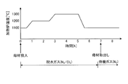
- FIG. 3 is a graph showing an example of changes in the temperature of the heating furnace and the time change of the dehydrated gas supplied according to the embodiment of the present invention.
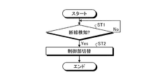
- FIG. 4 is a flowchart for explaining a heater control method according to an embodiment of the present invention.
- FIG. 5 is a diagram corresponding to FIG. 2 showing an example in which a disconnection occurs in the heating portion of the heater according to the embodiment of the present invention.
- FIG. 6 is a cross-sectional view corresponding to FIG. 2 according to a modified example of the embodiment of the present invention.
- FIG. 1 shows a heating device according to this embodiment.
- the heating furnace 1 as a heating device according to one embodiment is for dehydrating or vitrifying a glass base material 10 such as an optical fiber base material.
- the heating furnace 1 includes a core tube 12, a laminated heater 14, a furnace body 16, and a control unit 20.
- the core tube 12 is a tube that is configured to accommodate the glass base material 10 and extends in the vertical direction corresponding to the shape of the glass base material 10, that is, in the longitudinal direction of the glass base material 10.
- the core tube 12 is made of, for example, quartz glass.
- the laminated heater 14 as a heating means is provided so that a plurality of heaters 14A are laminated in the vertical direction on the outer periphery of the core tube 12. In the example shown in FIG. 1, 10 heaters 14A are laminated to form a laminated heater 14.
- the laminated heater 14 is controlled by the control unit 20 to be configured to be able to heat the core tube 12.
- Each heater 14A of the laminated heater 14 is configured by using, for example, molybdenum dissilicate (MoSi 2 ).
- the furnace body 16 houses the core tube 12 and the laminated heater 14.
- the furnace body 16 is made of a metal such as stainless steel.
- a cooling water system, a mold temperature controller, and the like may be further provided on the outer peripheral side of the laminated heater 14 in the furnace body 16.
- the upper end of the core tube 12 is covered with a simple hood 32.
- An inlet 34 for inserting and removing the glass base material 10 and an upper lid 35 for opening and closing the inlet 34 are provided on the upper part of the core tube 12.
- the upper lid 35 is provided with a discharge pipe 30, and gas is discharged (exhausted) from the core pipe 12 through the discharge pipe 30.
- a gate valve 33 is provided between the simple hood 32 and the discharge pipe 30.
- An introduction port 36 is provided at the lower end of the core tube 12. Gas is introduced (intake) into the core tube 12 through the introduction port 36.
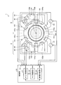
- FIG. 2 is a cross-sectional view taken along the line II-II of FIG.
- a plurality of individual heaters 14A constituting the laminated heater 14 in the heating furnace 1 are provided along the outer circumference of the core tube 12, and in this embodiment, ten heating portions 141a, 142a, 141b, 142b. , 141c, 143a, 144a, 143b, 144b, 143c are sequentially arranged in the same circle. That is, the heating units 141a to 143c are arranged side by side at substantially equidistant distances from their centers. It is preferable that each heater 14A has at least 10 heating portions.
- the heating units 141a to 144b are, for example, coil-shaped members made of a material containing, for example, MoSi 2 .
- the heater diameter (thickness) of the heating portions 141a to 144b is typically 10 mm or more, preferably 12 mm or more, and in the present embodiment, for example, 14 mm in order to ensure the durability of the heater 14A.
- the heating portion is spatially divided into two regions A and B.
- the heating portions 141a, 142a, 141b, 142b, 141c are provided in the region A.
- the heating portions 143a, 144a, 143b, 144b, 143c are provided in the region B.
- the heating portions 141a to 142b provided in the region A and the heating portions 143a to 144b provided in the region B are plane-symmetrical with respect to the boundary surface (dotted chain line in FIG. 2) of the regions A and B. It is provided so as to be rotationally symmetric with respect to the central axis O of rotation of the glass base material 10. As a result, the temperature distribution generated by heating the heater 14A in the regions A and B can be made symmetrical between the regions A and B.
- the heating group has at least one heating unit, typically a plurality of heating units, and the heating units 141a to 141c of the heating group 141 can control the calorific value by one power source 41, and the heating unit 142a of the heating group 142, The calorific value of 142b can be controlled by the other power supply 42.
- the power supplies 41 and 42 are power supply devices that can be controlled independently of each other.
- the power supplies 41 and 42 are preferably provided independently for each of the plurality of stages of heaters 14A.
- the heating portions 141a to 141c and the heating portions 142a and 142b are plane-symmetrical with respect to a plane (two-dot chain line in FIG. 2) (hereinafter, orthogonal plane) orthogonal to the boundary plane of the above-mentioned regions A and B. It is arranged. Further, the heating units 141a to 141c whose heat generation is controlled by the power supply 41 and the heating units 142a and 142b whose heat generation is controlled by the power supply 42 are alternately arranged along the outer circumference of the core tube 12.
- the other heating group heats the core tube 12 symmetrically with respect to the above-mentioned orthogonal plane. it can. Therefore, the other heating group can perform heating in a well-balanced manner so that the temperature distribution on the outer circumference of the core tube 12 is symmetrical.
- heating units 143a to 143c are connected in series to form a heating group 143, and power can be supplied from the power supply 43.
- the two heating units 144a and 144b are connected in series to form the heating group 144, and the power supply 44 can supply electric power.
- the calorific value of the heating units 143a to 143c of the heating group 143 can be controlled by one power supply 43
- the calorific value of the heating units 144a and 144b of the heating group 144 can be controlled by the other power supply 44.
- the power supplies 43 and 44 are power supply devices that can be controlled independently of each other.
- the power supplies 43 and 44 are provided independently for each of the plurality of stages of heaters 14A.
- the heating units 143a to 143c and the heating units 144a and 144b are arranged so as to be plane-symmetric with respect to the orthogonal plane. Further, the heating units 143a to 143c whose heat generation is controlled by the power supply 43 and the heating units 144a and 144b whose heat generation is controlled by the power supply 44 are alternately arranged along the outer circumference of the core tube 12. As a result, even if one of the heating groups 143 and 144 does not function and heat cannot be generated, the other heating group can heat the core tube 12 symmetrically with respect to the orthogonal plane. The heating can be performed in a well-balanced manner so that the temperature distribution on the outer periphery of the core tube 12 becomes symmetrical depending on the heating group of.
- the heating portions constituting the heating group are divided into two regions A and B, but it is also possible to divide the heating portions into three or more regions. Specifically, when the heating portion is divided into three or more odd-numbered regions, each heating portion is arranged so as to be rotationally symmetric with respect to the central axis O of rotation of the glass base material 10. Is preferable. Similarly, when the heating unit is divided into four or more even-numbered regions and arranged, as in the case where the heating unit is divided into two regions A and B, each heating portion is divided into two regions. On the other hand, it is preferable to arrange the components so that they are plane symmetric and rotationally symmetric even times with respect to the central axis O.
- the installation position of the temperature sensor is not limited. Further, even when the heating unit is divided into three or more regions, it is desirable to install one temperature sensor in each region, but the installation position is not necessarily limited.
- the heating parts constituting the heating group may be arranged without dividing the area. That is, a plurality of heating groups may be provided in one region. For example, when two heating groups are arranged on the outer periphery of the core tube 12, a plurality of heating units constituting one heating group are connected, electric power is supplied from one power source, and a plurality of heating groups constituting the other heating group are supplied. The heating part of is connected, and power is supplied from the other power source. On that basis, it is preferable that the plurality of heating parts of one heating group and the plurality of heating parts of the other heating group are alternately arranged along the outer circumference of the core tube 12. Thereby, the same effect as described above can be obtained.
- the plurality of heating parts of one heating group and the plurality of heating parts of the other heating group may be arranged so as to be plane-symmetric with respect to the plane passing through the central axis O. Even when three or more heating groups are provided, it is preferable to arrange a plurality of heating parts constituting each heating group so that the temperature distribution along the outer circumference of the core tube 12 does not vary.
- a plurality of heaters 14A configured as described above are configured to be stacked, and each heater 14A is controlled by the control unit 20, so that heating by the laminated heater 14 is controlled.
- the control unit 20 includes a main control unit 21, a sub control unit 22, a disconnection determination unit 23, and a signal selector 24. Information can be input / output by signals between the main control unit 21, the sub control unit 22, and the disconnection determination unit 23.
- the signal selector 24 switches the signal input by inputting the signal supplied to the control unit 20 from the outside to either the main control unit 21 or the sub control unit 22, while the main control unit 21 or the sub control
- the signal output from the unit 22 is selectively output to a predetermined output destination.
- control unit 20 includes processors such as a CPU (Central Processing Unit), DSP (Digital Signal Processor), FPGA (Field-Programmable Gate Array), RAM (Random Access Memory), ROM (Read Only Memory), and the like. (Neither of them is shown).
- the control unit includes a storage unit (not shown).
- the storage unit is composed of a storage medium selected from EPROM (Erasable Programmable ROM), hard disk drive (HDD, Hard Disk Drive), removable media, and the like.
- the removable media is, for example, a USB (Universal Serial Bus) memory or a disc recording medium such as a CD (Compact Disc), a DVD (Digital Versatile Disc), or a BD (Blu-ray (registered trademark) Disc). is there.
- the storage unit can store an operating system (OS), various programs, various tables, various databases, and the like.
- the control unit 20 loads the program stored in the storage unit into the work area of the main storage unit and executes it, and controls each component or the like through the execution of the program to realize a function that meets a predetermined purpose. ..
- the control unit 20 can realize the functions of the main control unit 21, the sub control unit 22, the disconnection determination unit 23, and the signal selector 24.
- Temperature sensors 45 and 46 as temperature measuring units are provided in regions A and B of the heater 14A, respectively.
- the temperature of the outer peripheral portion of the core tube 12 is measured by the temperature sensors 45 and 46.
- the measured value of the temperature is supplied to the control unit 20.
- the measured value of the temperature supplied to the control unit 20 is supplied to the main control unit 21 or the sub control unit 22 by the signal selector 24.
- the control unit 20 independently controls the power supplies 41 to 44 as the power supply units of the heater 14A based on the measured values of the supplied temperature. That is, the control unit 20 independently controls each of the power supplies 41 to 44 so that the measured value of the temperature measured by the temperature sensors 45 and 46 becomes an appropriate temperature.
- FIG. 3 is a graph showing an example of time changes in the temperature of the heating furnace 1 and the dehydration gas supplied.
- the power supplies 41 to 44 are controlled by the main control unit 21 of the control unit 20, and power is supplied from the power supplies 41 to 44 to each heater 14A composed of a plurality of stages to heat the heaters 14A.
- the heating temperature is adjusted to about 1000 to 1100 ° C. to protect the core tube 12.
- the glass base material 10 serving as the fiber base material is inserted into the core tube 12.
- dehydration gas is supplied from the outside into the core tube 12 through the introduction port 36 at the bottom.
- the dehydration gas is a mixed gas of a halogen gas such as chlorine (Cl 2 ) and an inert gas such as nitrogen (N 2 ) or helium (He).
- the gas in the core tube 12 rises and is exhausted from the upper discharge pipe 30.
- the electric power supplied to the laminated heater 14 is increased, and the heating temperature in the core tube 12 is adjusted to about 1200 to 1300 ° C. to make the glass.
- the base metal 10 is dehydrated.
- FIG. 4 is a flowchart for explaining a control method of the heater 14A according to the present embodiment.
- the disconnection determination unit 23 determines the presence or absence of disconnection based on the output of the power supplies 41 to 44. Detect.
- the disconnection determination unit 23 determines whether or not any of the heating units 141a to 144b is disconnected based on the voltage value supplied from the power supplies 41 to 44 while the heater 14A is heating. To do.
- step ST1 determines that none of the heating units 141a to 144b is disconnected (step ST1: No)
- step ST1 is repeatedly executed.
- FIG. 5 is a diagram showing an example of a state in which the heating portion of the heater 14A is disconnected.
- the heating portion 141b of the heating group 141 in the region A is disconnected.
- the disconnection determination unit 23 switches the control of the power supplies 43 and 44 in the region B, which is the region on the side where the disconnection does not occur, from the main control unit 21 to the sub control unit 22 by switching the signal selector 24.
- the disconnection determination unit 23 maintains the control of the main control unit 21 with respect to the power supply 42 that supplies power to the heating group 142 in which the disconnection has not occurred in the region A which is the region on the side where the disconnection has occurred.
- the main control unit 21 controls one power supply 41 and two heating units 142a and 142b based on the temperature measurement value from the temperature sensor 45 to adjust the temperature distribution in the region A. ..
- the main control unit 21 controls the power supply 41 so that the temperature distribution of the outer peripheral portion of the core tube 12 approaches the same temperature distribution as when heated by the heating groups 141 and 142.
- the sub control unit 22 controls the two power supplies 43 and 44 and the five heating units 143a to 144b based on the temperature measurement value from the temperature sensor 46 to adjust the temperature distribution in the region B. To do. As described above, the control process of the heater 14A is performed.
- the porous optical fiber mother is formed by forming the core and the porous glass on the outer periphery of the core by a conventionally known method such as the VAD method.
- a material glass base material 10
- the produced porous optical fiber base material is put into the core tube 12 of the heating furnace 1, and then heated and dehydrated in an atmosphere containing at least a dehydrating gas. Then, by further sintering the porous glass to make it transparent, a glass base material to be an optical fiber base material is produced.
- one of the heating groups 141 became unable to generate heat due to the disconnection of the heating unit 141b. Even in this case, the heating of the core tube 12 can be continued by the other heating group 142. Therefore, the heat generation defect of the heating group 141 can be covered by the heat generation of the heating group 142, and the possibility that the dehydration treatment of the glass base material 10 is interrupted can be reduced.
- the dehydration step of the glass base material 10 is lost in the core tube 12. It is possible to improve the possibility that the process can be completed without causing problems such as transparency.
- FIG. 6 is a cross-sectional view taken along the line II-II of FIG. 1 in the heating device according to the modified example.
- FIG. 6 there are a plurality of individual heaters 14B constituting the laminated heater 14 in the heating furnace 1 along the outer circumference of the core tube 12, and in this embodiment, six heating portions 147a, 146a, 147b, 149a. , 148a, 149b are sequentially arranged in the same circle. That is, the heating units 146a to 149b are arranged side by side at substantially equidistant distances from their centers. It is preferable that each heater 14B has at least 6 heating portions.
- the heating portions 146a to 149b are, for example, coil-shaped members made of a material containing, for example, MoSi 2 .
- the heater diameter (thickness) of the heating portions 146a to 149b is typically 10 mm or more, preferably 12 mm or more, and in this modified example, for example, 14 mm in order to ensure the durability of the heater 14B.
- the heating portion is spatially divided into two regions A and B.
- the heating portions 147a, 146a, and 147b are provided in the region A.
- the heating portions 149a, 148a, and 149b are provided in the region B.
- the heating portions 147a, 146a, 147b provided in the region A and the heating portions 149a, 148a, 149b provided in the region B are relative to each other with respect to the boundary surface (dotted chain line in FIG. 6) of the regions A and B. It is provided so as to be plane-symmetrical and rotationally symmetric with respect to the central axis O of rotation of the glass base material 10. As a result, the temperature distribution generated by heating the heater 14B in the regions A and B can be made symmetrical between the regions A and B.
- the heating group 146 is configured by one heating unit 146a, and power can be supplied from the power supply 41.
- two heating units 147a and 147b are connected in series to form a heating group 147, so that electric power can be supplied from the power supply 42.
- the heating group has at least one heating unit, the heating unit 146a of the heating group 146 can control the calorific value by one power supply 41, and the heating units 147a and 147b of the heating group 147 generate heat by the other power supply 42. The amount can be controlled.
- the power supplies 41 and 42 are power supply devices that can be controlled independently of each other.
- the power supplies 41 and 42 are preferably provided independently for each of the plurality of stages of heaters 14B.
- the heating portions 146a and the heating portions 147a and 147b are arranged so as to be plane-symmetric with respect to a plane (two-dot chain line in FIG. 2) (hereinafter, orthogonal plane) orthogonal to the boundary plane of the above-mentioned regions A and B. ing. Further, the heating units 146a whose heat generation is controlled by the power supply 41 and the heating units 147a and 147b whose heat generation is controlled by the power supply 42 are alternately arranged along the outer circumference of the core tube 12.
- the other heating group heats the core tube 12 symmetrically with respect to the above-mentioned orthogonal plane. it can. Therefore, the other heating group can perform heating in a well-balanced manner so that the temperature distribution on the outer circumference of the core tube 12 is symmetrical.
- the heating group 148 is configured by one heating unit 148a, and power can be supplied from the power supply 43.
- the two heating units 149a and 149b are connected in series to form the heating group 149, and the power supply 44 can supply electric power.
- the calorific value of the heating unit 148a of the heating group 148 can be controlled by one power supply 43
- the calorific value of the heating units 149a and 149b of the heating group 149 can be controlled by the other power supply 44.
- the power supplies 43 and 44 are power supply devices that can be controlled independently of each other. It is preferable that the power supplies 43 and 44 are provided independently for each of the plurality of stages of heaters 14B.
- the heating portions 148a and the heating portions 149a and 149b are arranged so as to be plane-symmetric with respect to the orthogonal plane. Further, the heating units 148a whose heat generation is controlled by the power supply 43 and the heating units 149a and 149b whose heat generation is controlled by the power supply 44 are alternately arranged along the outer circumference of the core tube 12. As a result, even if one of the heating groups 148 and 149 does not function and heat cannot be generated, the other heating group can heat the core tube 12 symmetrically with respect to the orthogonal plane. The heating can be performed in a well-balanced manner so that the temperature distribution on the outer periphery of the core tube 12 becomes symmetrical depending on the heating group of.
- the present invention is not limited to the above-mentioned one embodiment, and various modifications based on the technical idea of the present invention are possible.
- the numerical values given in the above-described embodiment are merely examples, and different numerical values may be used if necessary.
- the control of the heating groups 143 and 144 in the region B where the disconnection does not occur is switched from the main control unit 21 to the sub control unit 22.
- the control of the heating groups 141 and 142 in the region A where the disconnection has occurred may be switched from the main control unit 21 to the sub control unit 22.
- the main control unit 21 and the sub control unit 22 may be physically composed of a single processor or the like, or may be composed of different processors or the like.
- the present invention is useful for manufacturing an optical fiber base material.
- Heating furnace 10 Glass base material 12 Core tube 14 Laminated heater 14A, 14B Heater 16 Furnace 20 Control unit 21 Main control unit 22 Sub control unit 23 Disconnection judgment unit 24 Signal selector 30 Discharge pipe 32 Simple hood 33 Gate valve 34 Input port 35 Top lid 36 Inlet 41, 42, 43, 44 Power supply 45, 46 Temperature sensor 141, 142, 143, 144, 146, 147, 148, 149 Heating group 141a, 141b, 141c, 142a, 142b, 143a, 143b, 143c , 144a, 144b, 146a, 147a, 147b, 148a, 149a, 149b Heating unit
Landscapes
- Engineering & Computer Science (AREA)
- Chemical & Material Sciences (AREA)
- General Engineering & Computer Science (AREA)
- Mechanical Engineering (AREA)
- Geochemistry & Mineralogy (AREA)
- Life Sciences & Earth Sciences (AREA)
- General Life Sciences & Earth Sciences (AREA)
- Manufacturing & Machinery (AREA)
- Materials Engineering (AREA)
- Organic Chemistry (AREA)
- General Chemical & Material Sciences (AREA)
- Physics & Mathematics (AREA)
- Chemical Kinetics & Catalysis (AREA)
- Thermal Sciences (AREA)
- Manufacture, Treatment Of Glass Fibers (AREA)
- Muffle Furnaces And Rotary Kilns (AREA)
- Resistance Heating (AREA)
Abstract
炉心管を加熱するヒータの信頼性を向上させて非稼働時間を短縮することにより、ガラス母材の製造コストを低コスト化することを目的とする。ガラス母材を収容可能な炉心管と、炉心管の外周に設けられた加熱手段と、加熱手段を制御する制御部と、を備え、加熱手段は、互いに独立して制御可能な複数のヒータがガラス母材の長手方向に沿って積層された構成を有し、ヒータは、制御部により互いに独立して制御可能な複数の加熱群を有し、加熱群は炉心管を加熱可能な少なくとも1つの加熱部からなる。加熱群はそれぞれ、加熱群に電力を供給可能な電源部を有し、制御部は、それぞれの加熱群における電源部を互いに独立して制御する。炉心管の温度を計測する温度計測部をさらに備え、制御部は、温度計測部による計測値に基づいて、それぞれの加熱群に供給する電力を調整する。
Description
本発明は、ガラス母材を製造するための加熱装置および光ファイバ母材の製造方法に関する。
特許文献1には、電気炉内の温度勾配を精密に制御することによって、光学特性に優れた光ファイバ母材を得るとともに、電気炉内にヒータを多段に設置しても電源装置の数が少なくて済み、省設備化が図れる構成として、複数のヒータからなる加熱群と、複数の該加熱群にそれぞれ対応して設けられた複数の電源部とを有し、各電源部が加熱群のいずれかのヒータに切り換え可能に接続されている構成が開示されている。特許文献1に記載された構成によれば、光ファイバの母材が大型化しても、母材に均一に低コストで加熱することができる。特許文献2には、二ケイ化モリブデン(MoSi2)からなる加熱ヒータを多段にした構成が開示されている。特許文献2に記載された加熱ヒータは、光ファイバ母材の長手方向の熱分布が均一になるように配置されている。
さて、ガラス母材である光ファイバ母材の大型化に伴って、脱水工程において使用される加熱装置のうち、とりわけ炉心管が大型化してきて高コスト化している。そのため、製造コストを上げないために、ヒータの断線などによる炉心管の劣化などを抑制して、交換などのメンテナンスの回数を低減し、加熱装置の非稼働時間を短縮することが求められている。
一般に、光ファイバの製造における脱水工程で使用されるヒータとしては、カーボンの放射熱を利用するカーボンヒータや、二ケイ化モリブデン(MoSi2)などの放射熱を用いた加熱ヒータがある。カーボンヒータは、炉心管の周方向に一体成形する必要がある。そのため、光ファイバ母材の大型化によって炉心管が大径化すると、炉心管の外周に嵌め込むカーボンヒータは高コスト化する。一方、二ケイ化モリブデンを用いたヒータは、周方向に分割して配置できるので、光ファイバ母材の大型化によって炉心管が大径化しても、配置するヒータの数を増加させることによって対応できるので、大きなコストの増加要因にならないという利点がある。しかしながら、二ケイ化モリブデンを用いたヒータは、カーボンヒータに比して劣化が早く信頼性がやや劣ることから、カーボンヒータに比して脱水工程における加熱中に断線する可能性が懸念される。
本発明は、上記に鑑みてなされたものであって、その目的は、ガラス母材の製造コストを低コスト化できる加熱装置および光ファイバ母材の製造方法を提供することにある。
上述した課題を解決し、上記目的を達成するために、本発明に係る加熱装置は、ガラス母材を収容可能な炉心管と、前記炉心管の外周に設けられた加熱手段と、前記加熱手段を制御する制御部と、を備え、前記加熱手段は、互いに独立して制御可能な複数のヒータが前記ガラス母材の長手方向に沿って配置された構成を有し、前記ヒータは、前記制御部により互いに独立して制御可能な複数の加熱群を有し、前記加熱群は前記炉心管を加熱可能な少なくとも1つの加熱部を有することを特徴とする。
本発明の一態様に係る加熱装置は、上記の発明において、前記加熱群はそれぞれ、前記加熱群に電力を供給可能な電源部を有し、前記制御部は、それぞれの前記加熱群における前記電源部を互いに独立して制御することを特徴とする。また、本発明の一態様に係る加熱装置は、この構成において、前記炉心管の温度を計測する温度計測部をさらに備え、前記制御部は、前記温度計測部による計測値に基づいて、それぞれの前記加熱群に供給する電力を調整することを特徴とする。
本発明の一態様に係る加熱装置は、上記の発明において、前記加熱群は、前記加熱部を複数有することを特徴とする。
本発明の一態様に係る加熱装置は、上記の発明において、前記ヒータは、前記加熱部を少なくとも6個有することを特徴とする。
本発明の一態様に係る加熱装置は、上記の発明において、前記加熱部は、二ケイ化モリブデンを用いて構成されることを特徴とする。
本発明の一態様に係る加熱装置は、上記の発明において、前記加熱部のヒータ径は、10mm以上であることを特徴とする。
本発明の一態様に係る光ファイバ母材の製造方法は、コアおよび前記コアの外周に形成された多孔質ガラスからなる多孔質光ファイバ母材を収容可能な炉心管と、前記炉心管の外周に設けられた加熱手段と、前記加熱手段を制御する制御部と、を備え、前記加熱手段は、互いに独立して制御可能な複数のヒータが前記多孔質光ファイバ母材の長手方向に沿って配置された構成を有し、前記ヒータは、前記制御部により互いに独立して制御可能な複数の加熱群を有し、前記加熱群は前記炉心管を加熱可能な少なくとも1つの加熱部を有する加熱装置を用いる光ファイバの製造方法であって、前記加熱装置の前記炉心管に前記多孔質光ファイバ母材を投入し、少なくとも脱水ガスを含む雰囲気で加熱脱水することを特徴とする。
本発明に係る加熱装置および光ファイバ母材の製造方法によれば、光ファイバ母材の製造コストを低コスト化することが可能となる。
以下、本発明の実施形態について図面を参照しつつ説明する。なお、以下の実施形態の全図においては、同一または対応する部分には同一の符号を付す。また、本発明は以下に説明する実施形態によって限定されるものではない。
まず、本発明の一実施形態による加熱装置について説明する。図1は、この一実施形態による加熱装置を示す。図1に示すように、一実施形態による加熱装置としての加熱炉1は、光ファイバ母材などのガラス母材10を脱水またはガラス化するためのものである。加熱炉1は、炉心管12と、積層ヒータ14と、炉体16と、制御部20とを備える。
炉心管12は、ガラス母材10を収容可能に構成され、ガラス母材10の形状に対応した上下方向、すなわちガラス母材10の長手方向に延びた菅である。炉心管12は、例えば石英ガラスなどから構成されている。加熱手段としての積層ヒータ14は、炉心管12の外周において上下方向に複数のヒータ14Aが積層するように設けられる。図1に示す例では、ヒータ14Aが10段積層されて積層ヒータ14が構成される。積層ヒータ14は、制御部20によって制御されて炉心管12を加熱可能に構成される。積層ヒータ14の各ヒータ14Aは、例えば二ケイ化モリブデン(MoSi2)を用いて構成される。炉体16は、炉心管12および積層ヒータ14を収容している。炉体16は、例えばステンレス鋼など金属から構成されている。なお、炉体16内における積層ヒータ14の外周側にさらに冷却水系統や金型温調機などをさらに備えても良い。
炉心管12の上端は、簡易フード32に覆われている。炉心管12の上部には、ガラス母材10を挿入したり取り出したりするための投入口34、および投入口34を開閉するための上蓋35が設けられている。上蓋35には、排出管30が設けられ、排出管30を介して炉心管12内からのガスの排出(排気)が行われる。簡易フード32と排出管30との間にはゲートバルブ33が設けられている。炉心管12の下端には、導入口36が設けられている。導入口36を介して炉心管12内へのガスの導入(吸気)が行われる。
図2は、図1のII-II線に沿った断面図である。図2に示すように、加熱炉1における積層ヒータ14を構成する個々のヒータ14Aは、炉心管12の外周に沿って複数、本実施形態においては10個の加熱部141a,142a,141b,142b,141c,143a,144a,143b,144b,143cが同一円状に順次並べられて構成される。すなわち、加熱部141a~143cは、それらの中心から略等距離に並べて配置されている。なお、それぞれのヒータ14Aは、加熱部を少なくとも10個有することが好ましい。また、本実施形態において加熱部141a~144bは、例えばMoSi2を含む材料から構成される例えばコイル状の部材である。加熱部141a~144bのヒータ径(太さ)は、ヒータ14Aの耐久性を確保するために、典型的には10mm以上、好適には12mm以上、本実施形態においては例えば14mmである。
図2に示すヒータ14Aは、加熱部が空間的に2つの領域A,Bに分けて配置されている。加熱部141a,142a,141b,142b,141cは、領域Aに設けられている。加熱部143a,144a,143b,144b,143cは、領域Bに設けられている。領域Aに設けられた加熱部141a~142bと、領域Bに設けられた加熱部143a~144bとは、互いに領域A,Bの境界面(図2中、一点鎖線)に対して面対称、かつガラス母材10の回転の中心軸Oに対して回転対称になるように設けられている。これにより、領域A,Bにおいてヒータ14Aの加熱によって生じる温度分布を、領域Aと領域Bとで対称的にできる。
ヒータ14Aの領域Aにおいて、3つの加熱部141a~141cが直列接続されて加熱群141が構成され、電源41から電力を供給可能に構成されている。一方、2つの加熱部142a,142bが直列接続されて加熱群142が構成され、電源42から電力を供給可能に構成されている。換言すると、加熱群は加熱部を少なくとも1つ、典型的には複数有し、加熱群141の加熱部141a~141cは一方の電源41によって発熱量が制御でき、加熱群142の加熱部142a,142bは他方の電源42によって発熱量が制御できる。電源41,42は、互いに独立して制御可能な電力供給装置である。電源41,42は、複数段のヒータ14Aのそれぞれに独立して設けることが好ましい。加熱部141a~141cおよび加熱部142a,142bは、上述した領域A,Bの境界面に直交する面(図2中、二点鎖線)(以下、直交面)に対して面対称になるように配置されている。さらに、電源41によって発熱が制御される加熱部141a~141cと、電源42によって発熱が制御される加熱部142a,142bとは、炉心管12の外周に沿って互いに交互に配置されている。これにより、断線などによって加熱群141,142のうちの一方の加熱群が機能せず発熱不能になった場合でも、他方の加熱群によって上述した直交面に対して対称的に炉心管12を加熱できる。したがって、他方の加熱群によって、炉心管12の外周の温度分布が対称になるように加熱をバランスよく行うことができる。
ヒータ14Aの領域Bにおいて、3つの加熱部143a~143cが直列接続されて加熱群143が構成され、電源43から電力を供給可能に構成されている。一方、2つの加熱部144a,144bが直列接続されて加熱群144が構成され、電源44から電力を供給可能に構成されている。換言すると、加熱群143の加熱部143a~143cは一方の電源43によって発熱量が制御でき、加熱群144の加熱部144a,144bは他方の電源44によって発熱量が制御できる。電源43,44は、互いに独立して制御可能な電力供給装置である。電源43,44は、複数段のヒータ14Aのそれぞれに独立して設けることが好ましい。加熱部143a~143cおよび加熱部144a,144bは、直交面に対して面対称になるように配置されている。さらに、電源43によって発熱が制御される加熱部143a~143cと、電源44によって発熱が制御される加熱部144a,144bとは、炉心管12の外周に沿って互いに交互に配置されている。これにより、加熱群143,144のうちの一方の加熱群が機能せず発熱不能になった場合でも、他方の加熱群によって、直交面に対して対称的に炉心管12を加熱できるので、他方の加熱群によって炉心管12の外周の温度分布が対称になるように、加熱をバランスよく行うことができる。
なお、本実施形態においては、加熱群を構成する加熱部を2つの領域A,Bに分けて配置しているが、3つ以上の領域に分けて配置することも可能である。具体的に、加熱部を3つ以上の奇数の領域に分けて配置する場合、それぞれの加熱部を、ガラス母材10の回転の中心軸Oに対して奇数回回転対称になるように配置することが好ましい。同様に、加熱部を4つ以上の偶数の領域に分けて配置する場合、2つの領域A,Bに分けて配置した場合と同様に、それぞれの加熱部を、領域を2つに分ける面に対して面対称、かつ中心軸Oに対して偶数回回転対称になるように配置することが好ましい。また、複数の領域のそれぞれに温度センサを設けることが好ましいが、温度センサの設置位置は限定されない。また、3つ以上の領域に分けて加熱部を配置する場合においても、それぞれの領域に1つずつ温度センサを設置することが望ましいが、必ずしも設置位置は限定されない。
また、加熱群を構成する加熱部を、領域を分けることなく配置しても良い。すなわち、1つの領域に複数の加熱群を設けるようにしても良い。例えば、炉心管12の外周に2つの加熱群を配置する場合、一方の加熱群を構成する複数の加熱部が接続されて、一方の電源から電力が供給され、他方の加熱群を構成する複数の加熱部が接続されて、他方の電源から電力が供給される。その上で、一方の加熱群の複数の加熱部と他方の加熱群の複数の加熱部とは、炉心管12の外周に沿って互いに交互に配置するのが好ましい。これにより、上述と同様の効果を得ることができる。なお、一方の加熱群の複数の加熱部と、他方の加熱群の複数の加熱部とを、中心軸Oを通る面に対して面対称になるように配置しても良い。加熱群を3つ以上設ける場合においても、それぞれの加熱群を構成する複数の加熱部を、炉心管12の外周に沿った温度の分布にばらつきが生じないように配置することが好ましい。
上述のように構成されたヒータ14Aを複数積層するように構成して、それぞれのヒータ14Aが制御部20によって制御されることで、積層ヒータ14による加熱が制御される。制御部20は、メイン制御部21、サブ制御部22、断線判定部23、および信号セレクタ24を有する。メイン制御部21とサブ制御部22と断線判定部23との間は、信号によって情報を入出力可能に構成されている。信号セレクタ24は、外部から制御部20に供給された信号を、メイン制御部21とサブ制御部22とのいずれかに入力する、信号の入力の切り替えを行う一方、メイン制御部21またはサブ制御部22から出力された信号を、所定の出力先に選択的に出力する。
制御部20は、具体的に、CPU(Central Processing Unit)、DSP(Digital Signal Processor)、FPGA(Field-Programmable Gate Array)などのプロセッサ、およびRAM(Random Access Memory)やROM(Read Only Memory)などの主記憶部(いずれも図示せず)を備える。制御部は記憶部(図示せず)を備える。記憶部は、EPROM(Erasable Programmable ROM)、ハードディスクドライブ(HDD、Hard Disk Drive)、およびリムーバブルメディアなどから選ばれた記憶媒体から構成される。なお、リムーバブルメディアは、例えば、USB(Universal Serial Bus)メモリ、または、CD(Compact Disc)、DVD(Digital Versatile Disc)、またはBD(Blu-ray(登録商標) Disc)のようなディスク記録媒体である。記憶部には、オペレーティングシステム(Operating System:OS)、各種プログラム、各種テーブル、各種データベースなどが格納可能である。制御部20は、記憶部に格納されたプログラムを主記憶部の作業領域にロードして実行し、プログラムの実行を通じて各構成部などを制御することで、所定の目的に合致した機能を実現できる。本実施形態において、制御部20は、メイン制御部21、サブ制御部22、断線判定部23、および信号セレクタ24の機能を実現できる。
ヒータ14Aの領域A,Bにはそれぞれ、温度計測部としての温度センサ45,46が設けられている。温度センサ45,46によって炉心管12の外周部分の温度が計測される。温度の計測値は、制御部20に供給される。制御部20に供給された温度の計測値は、信号セレクタ24によって、メイン制御部21またはサブ制御部22に供給される。制御部20は、供給された温度の計測値に基づいて、ヒータ14Aの電源部としての電源41~44をそれぞれ独立に制御する。すなわち、制御部20は温度センサ45,46によって計測された温度の計測値が適切な温度になるように、電源41~44のそれぞれを互いに独立して制御する。
次に、上述した加熱炉1によるガラス母材10の加熱動作について説明する。図3は、加熱炉1の温度および供給する脱水ガスの時間変化の一例を示すグラフである。図3に示すように、まず、制御部20のメイン制御部21によって電源41~44が制御されて、電源41~44から複数段で構成されたそれぞれのヒータ14Aに電力を供給して加熱を開始する。ここで、加熱炉1内にガラス母材10が投入されておらず待機中の場合、加熱温度は、炉心管12の保護のために約1000~1100℃程度に調節される。次に、炉心管12内にファイバ母材となるガラス母材10を挿入する。一方で、外部から炉心管12内に、底部の導入口36を通じて脱水ガスを供給する。脱水ガスは、例えば塩素(Cl2)などのハロゲンガスと窒素(N2)またはヘリウム(He)などの不活性ガスとの混合ガスである。炉心管12内のガスは上昇して上部の排出管30から排気される。加熱炉1の炉心管12にガラス母材10が投入された後は、積層ヒータ14に供給する電力を増加させ、炉心管12内の加熱温度を約1200~1300℃に調節することにより、ガラス母材10の脱水処理が行われる。
次に、ヒータ14Aの制御方法について説明する。図4は、本実施形態によるヒータ14Aの制御方法を説明するためのフローチャートである。図4に示すように、ステップST1において制御部20のメイン制御部21が電源41~44を制御している間に、断線判定部23が電源41~44の出力に基づいて、断線の有無を検知する。断線判定部23は、ヒータ14Aによる加熱が行われている間に、電源41~44から供給される電圧値などに基づいて、加熱部141a~144bのいずれかが断線しているか否かを判定する。断線判定部23が、加熱部141a~144bのいずれも断線していないと判定した場合(ステップST1:No)、ステップST1を繰り返し実行する。
断線判定部23が、加熱部141a~144bのいずれかが断線していると判定した場合(ステップST1:Yes)、ステップST2に移行する。図5は、ヒータ14Aの加熱部に断線が生じた状態の例を示す図である。図5に示す例においては、領域Aの加熱群141の加熱部141bに断線が生じている。ステップST2において断線判定部23は、信号セレクタ24を切り替えることによって、断線が生じていない側の領域である領域Bの電源43,44に対する制御を、メイン制御部21からサブ制御部22に切り替える。一方、断線判定部23は、断線が生じた側の領域である領域Aにおいて、断線が生じていない加熱群142に電力を供給する電源42に対するメイン制御部21の制御を維持する。これにより、ヒータ14Aにおいて、メイン制御部21は、温度センサ45からの温度の計測値に基づいて1つの電源41および2つの加熱部142a,142bを制御して、領域Aにおける温度分布を調整する。ここで、メイン制御部21は、炉心管12の外周部分の温度分布が、加熱群141,142によって加熱されている場合と同様の温度分布に近づくように電源41を制御する。一方、ヒータ14Aにおいて、サブ制御部22は、温度センサ46からの温度の計測値に基づいて2つの電源43,44および5つの加熱部143a~144bを制御して、領域Bにおける温度分布を調整する。以上により、ヒータ14Aの制御処理が行われる。
次に、加熱炉1を用いた光ファイバ母材の製造方法においては、まず、VAD法などの従来公知の方法によりコアおよびコアの外周に多孔質ガラスを形成することにより、多孔質光ファイバ母材(ガラス母材10)を製造する。次に、製造した多孔質光ファイバ母材を加熱炉1の炉心管12内に投入した後、少なくとも脱水ガスを含む雰囲気で加熱脱水する。その後、さらに多孔質ガラスを焼結して透明ガラス化することにより、光ファイバ母材となるガラス母材が製造される。
以上説明した本発明の一実施形態によれば、例えば領域Aにおいて直列接続されている2つの加熱群141,142のうち、一方の加熱群141が、加熱部141bの断線によって発熱不能になった場合であっても、他方の加熱群142によって炉心管12の加熱を継続できる。そのため、加熱群141の発熱不良を加熱群142の発熱によってカバーでき、ガラス母材10の脱水処理が中断する可能性を低減できる。すなわち、複数段で構成された積層ヒータ14において、一部のヒータ14Aに断線などの不具合が生じて発熱不能の加熱群141が生じても、ガラス母材10の脱水工程を炉心管12の失透などの不具合を生じさせることなく終了できる可能性を向上できる。
(変形例)
次に、上述した一実施形態の変形例について説明する。図6は、変形例による加熱装置における図1のII-II線に沿った断面図である。図6に示すように、加熱炉1における積層ヒータ14を構成する個々のヒータ14Bは、炉心管12の外周に沿って複数、本実施形態においては6個の加熱部147a,146a,147b,149a,148a,149bが同一円状に順次並べられて構成される。すなわち、加熱部146a~149bは、それらの中心から略等距離に並べて配置されている。なお、それぞれのヒータ14Bは、加熱部を少なくとも6個有することが好ましい。また、本変形例において加熱部146a~149bは、例えばMoSi2を含む材料から構成される例えばコイル状の部材である。加熱部146a~149bのヒータ径(太さ)は、ヒータ14Bの耐久性を確保するために、典型的には10mm以上、好適には12mm以上、本変形例においては例えば14mmである。
次に、上述した一実施形態の変形例について説明する。図6は、変形例による加熱装置における図1のII-II線に沿った断面図である。図6に示すように、加熱炉1における積層ヒータ14を構成する個々のヒータ14Bは、炉心管12の外周に沿って複数、本実施形態においては6個の加熱部147a,146a,147b,149a,148a,149bが同一円状に順次並べられて構成される。すなわち、加熱部146a~149bは、それらの中心から略等距離に並べて配置されている。なお、それぞれのヒータ14Bは、加熱部を少なくとも6個有することが好ましい。また、本変形例において加熱部146a~149bは、例えばMoSi2を含む材料から構成される例えばコイル状の部材である。加熱部146a~149bのヒータ径(太さ)は、ヒータ14Bの耐久性を確保するために、典型的には10mm以上、好適には12mm以上、本変形例においては例えば14mmである。
図6に示すヒータ14Bは、加熱部が空間的に2つの領域A,Bに分けて配置されている。加熱部147a,146a,147bは、領域Aに設けられている。加熱部149a,148a,149bは、領域Bに設けられている。領域Aに設けられた加熱部147a,146a,147bと、領域Bに設けられた加熱部149a,148a,149bとは、互いに領域A,Bの境界面(図6中、一点鎖線)に対して面対称、かつガラス母材10の回転の中心軸Oに対して回転対称になるように設けられている。これにより、領域A,Bにおいてヒータ14Bの加熱によって生じる温度分布を、領域Aと領域Bとで対称的にできる。
ヒータ14Bの領域Aにおいて、1つの加熱部146aによって加熱群146が構成され、電源41から電力を供給可能に構成されている。一方、2つの加熱部147a,147bが直列接続されて加熱群147が構成され、電源42から電力を供給可能に構成されている。換言すると、加熱群は加熱部を少なくとも1つ有し、加熱群146の加熱部146aは一方の電源41によって発熱量が制御でき、加熱群147の加熱部147a,147bは他方の電源42によって発熱量が制御できる。電源41,42は、互いに独立して制御可能な電力供給装置である。電源41,42は、複数段のヒータ14Bのそれぞれに独立して設けることが好ましい。加熱部146aおよび加熱部147a,147bは、上述した領域A,Bの境界面に直交する面(図2中、二点鎖線)(以下、直交面)に対して面対称になるように配置されている。さらに、電源41によって発熱が制御される加熱部146aと、電源42によって発熱が制御される加熱部147a,147bとは、炉心管12の外周に沿って互いに交互に配置されている。これにより、断線などによって加熱群146,147のうちの一方の加熱群が機能せず発熱不能になった場合でも、他方の加熱群によって上述した直交面に対して対称的に炉心管12を加熱できる。したがって、他方の加熱群によって、炉心管12の外周の温度分布が対称になるように加熱をバランスよく行うことができる。
ヒータ14Bの領域Bにおいて、1つの加熱部148aによって加熱群148が構成され、電源43から電力を供給可能に構成されている。一方、2つの加熱部149a,149bが直列接続されて加熱群149が構成され、電源44から電力を供給可能に構成されている。換言すると、加熱群148の加熱部148aは一方の電源43によって発熱量が制御でき、加熱群149の加熱部149a,149bは他方の電源44によって発熱量が制御できる。電源43,44は、互いに独立して制御可能な電力供給装置である。電源43,44は、複数段のヒータ14Bのそれぞれに独立して設けることが好ましい。加熱部148aおよび加熱部149a,149bは、直交面に対して面対称になるように配置されている。さらに、電源43によって発熱が制御される加熱部148aと、電源44によって発熱が制御される加熱部149a,149bとは、炉心管12の外周に沿って互いに交互に配置されている。これにより、加熱群148,149のうちの一方の加熱群が機能せず発熱不能になった場合でも、他方の加熱群によって、直交面に対して対称的に炉心管12を加熱できるので、他方の加熱群によって炉心管12の外周の温度分布が対称になるように、加熱をバランスよく行うことができる。
以上のように、一実施形態の変形例においても、上述した一実施形態と同様の効果を得ることができる。
以上、本発明の一実施形態について具体的に説明したが、本発明は、上述の一実施形態に限定されるものではなく、本発明の技術的思想に基づく各種の変形が可能である。例えば、上述の一実施形態において挙げた数値はあくまでも例に過ぎず、必要に応じてこれと異なる数値を用いても良い。
例えば、上述した一実施形態においては、断線などが発生した場合に、断線が発生していない領域Bの加熱群143,144の制御をメイン制御部21からサブ制御部22に切り替えているが、断線が発生した領域Aの加熱群141,142の制御をメイン制御部21からサブ制御部22に切り替えても良い。また、メイン制御部21およびサブ制御部22は物理的に単一のプロセッサなどから構成しても互いに異なるプロセッサなどから構成しても良い。
本発明は、光ファイバ母材の製造に有用である。
1 加熱炉
10 ガラス母材
12 炉心管
14 積層ヒータ
14A,14B ヒータ
16 炉体
20 制御部
21 メイン制御部
22 サブ制御部
23 断線判定部
24 信号セレクタ
30 排出管
32 簡易フード
33 ゲートバルブ
34 投入口
35 上蓋
36 導入口
41,42,43,44 電源
45,46 温度センサ
141,142,143,144,146,147,148,149 加熱群
141a,141b,141c,142a,142b,143a,143b,143c,144a,144b,146a,147a,147b,148a,149a,149b 加熱部
10 ガラス母材
12 炉心管
14 積層ヒータ
14A,14B ヒータ
16 炉体
20 制御部
21 メイン制御部
22 サブ制御部
23 断線判定部
24 信号セレクタ
30 排出管
32 簡易フード
33 ゲートバルブ
34 投入口
35 上蓋
36 導入口
41,42,43,44 電源
45,46 温度センサ
141,142,143,144,146,147,148,149 加熱群
141a,141b,141c,142a,142b,143a,143b,143c,144a,144b,146a,147a,147b,148a,149a,149b 加熱部
Claims (8)
- ガラス母材を収容可能な炉心管と、
前記炉心管の外周に設けられた加熱手段と、
前記加熱手段を制御する制御部と、を備え、
前記加熱手段は、互いに独立して制御可能な複数のヒータが前記ガラス母材の長手方向に沿って配置された構成を有し、
前記ヒータは、前記制御部により互いに独立して制御可能な複数の加熱群を有し、
前記加熱群は前記炉心管を加熱可能な少なくとも1つの加熱部を有する
ことを特徴とする加熱装置。 - 前記加熱群はそれぞれ、前記加熱群に電力を供給可能な電源部を有し、前記制御部は、それぞれの前記加熱群における前記電源部を互いに独立して制御する
ことを特徴とする請求項1に記載の加熱装置。 - 前記炉心管の温度を計測する温度計測部をさらに備え、
前記制御部は、前記温度計測部による計測値に基づいて、それぞれの前記加熱群に供給する電力を調整する
ことを特徴とする請求項2に記載の加熱装置。 - 前記加熱群は、前記加熱部を複数有する
ことを特徴とする請求項1~3のいずれか1項に記載の加熱装置。 - 前記ヒータは、前記加熱部を少なくとも6個有する
ことを特徴とする請求項1~4のいずれか1項に記載の加熱装置。 - 前記加熱部は、二ケイ化モリブデンを用いて構成される
ことを特徴とする請求項1~5のいずれか1項に記載の加熱装置。 - 前記加熱部のヒータ径は、10mm以上である
ことを特徴とする請求項1~6のいずれか1項に記載の加熱装置。 - コアおよび前記コアの外周に形成された多孔質ガラスからなる多孔質光ファイバ母材を収容可能な炉心管と、前記炉心管の外周に設けられた加熱手段と、前記加熱手段を制御する制御部と、を備え、前記加熱手段は、互いに独立して制御可能な複数のヒータが前記多孔質光ファイバ母材の長手方向に沿って配置された構成を有し、前記ヒータは、前記制御部により互いに独立して制御可能な複数の加熱群を有し、前記加熱群は前記炉心管を加熱可能な少なくとも1つの加熱部を有する加熱装置を用いる光ファイバの製造方法であって、
前記加熱装置の前記炉心管に前記多孔質光ファイバ母材を投入し、
少なくとも脱水ガスを含む雰囲気で加熱脱水する
ことを特徴とする光ファイバ母材の製造方法。
Priority Applications (3)
| Application Number | Priority Date | Filing Date | Title |
|---|---|---|---|
| JP2021524876A JPWO2020246499A1 (ja) | 2019-06-06 | 2020-06-03 | |
| CN202080041072.4A CN113924275B (zh) | 2019-06-06 | 2020-06-03 | 加热装置及光纤母材的制造方法 |
| US17/455,802 US20220073405A1 (en) | 2019-06-06 | 2021-11-19 | Heating apparatus and method for manufacturing optical fiber base material |
Applications Claiming Priority (2)
| Application Number | Priority Date | Filing Date | Title |
|---|---|---|---|
| JP2019-106565 | 2019-06-06 | ||
| JP2019106565 | 2019-06-06 |
Related Child Applications (1)
| Application Number | Title | Priority Date | Filing Date |
|---|---|---|---|
| US17/455,802 Continuation US20220073405A1 (en) | 2019-06-06 | 2021-11-19 | Heating apparatus and method for manufacturing optical fiber base material |
Publications (1)
| Publication Number | Publication Date |
|---|---|
| WO2020246499A1 true WO2020246499A1 (ja) | 2020-12-10 |
Family
ID=73652203
Family Applications (1)
| Application Number | Title | Priority Date | Filing Date |
|---|---|---|---|
| PCT/JP2020/021921 Ceased WO2020246499A1 (ja) | 2019-06-06 | 2020-06-03 | 加熱装置および光ファイバ母材の製造方法 |
Country Status (4)
| Country | Link |
|---|---|
| US (1) | US20220073405A1 (ja) |
| JP (1) | JPWO2020246499A1 (ja) |
| CN (1) | CN113924275B (ja) |
| WO (1) | WO2020246499A1 (ja) |
Families Citing this family (1)
| Publication number | Priority date | Publication date | Assignee | Title |
|---|---|---|---|---|
| CN122380636A (zh) * | 2026-06-16 | 2026-07-14 | 咸阳彩虹光伏玻璃有限公司 | 一种快速切换生产家电玻璃的钢化工艺 |
Citations (5)
| Publication number | Priority date | Publication date | Assignee | Title |
|---|---|---|---|---|
| JPS63182231A (ja) * | 1987-01-21 | 1988-07-27 | Sumitomo Electric Ind Ltd | 光フアイバ母材製造用脱水焼結炉 |
| JPH03223133A (ja) * | 1990-01-30 | 1991-10-02 | Fujikura Ltd | 脱水焼結炉 |
| JP2002299250A (ja) * | 2001-03-29 | 2002-10-11 | Tokyo Electron Ltd | 熱処理装置用ヒータの結線方法及び熱処理装置 |
| JP2004224655A (ja) * | 2003-01-24 | 2004-08-12 | Shin Etsu Chem Co Ltd | 光ファイバ母材の透明ガラス化装置及び方法 |
| JP2016088821A (ja) * | 2014-11-10 | 2016-05-23 | 信越化学工業株式会社 | 光ファイバ用多孔質ガラス母材の焼結装置及び焼結方法 |
Family Cites Families (3)
| Publication number | Priority date | Publication date | Assignee | Title |
|---|---|---|---|---|
| KR890008922A (ko) * | 1987-11-21 | 1989-07-13 | 후세 노보루 | 열처리 장치 |
| CN1152835C (zh) * | 1998-08-31 | 2004-06-09 | 住友电气工业株式会社 | 玻璃物品的制造方法和光纤用玻璃母材 |
| JP4712359B2 (ja) * | 2004-11-29 | 2011-06-29 | 古河電気工業株式会社 | 光ファイバの製造方法 |
-
2020
- 2020-06-03 CN CN202080041072.4A patent/CN113924275B/zh active Active
- 2020-06-03 WO PCT/JP2020/021921 patent/WO2020246499A1/ja not_active Ceased
- 2020-06-03 JP JP2021524876A patent/JPWO2020246499A1/ja active Pending
-
2021
- 2021-11-19 US US17/455,802 patent/US20220073405A1/en not_active Abandoned
Patent Citations (5)
| Publication number | Priority date | Publication date | Assignee | Title |
|---|---|---|---|---|
| JPS63182231A (ja) * | 1987-01-21 | 1988-07-27 | Sumitomo Electric Ind Ltd | 光フアイバ母材製造用脱水焼結炉 |
| JPH03223133A (ja) * | 1990-01-30 | 1991-10-02 | Fujikura Ltd | 脱水焼結炉 |
| JP2002299250A (ja) * | 2001-03-29 | 2002-10-11 | Tokyo Electron Ltd | 熱処理装置用ヒータの結線方法及び熱処理装置 |
| JP2004224655A (ja) * | 2003-01-24 | 2004-08-12 | Shin Etsu Chem Co Ltd | 光ファイバ母材の透明ガラス化装置及び方法 |
| JP2016088821A (ja) * | 2014-11-10 | 2016-05-23 | 信越化学工業株式会社 | 光ファイバ用多孔質ガラス母材の焼結装置及び焼結方法 |
Also Published As
| Publication number | Publication date |
|---|---|
| US20220073405A1 (en) | 2022-03-10 |
| JPWO2020246499A1 (ja) | 2020-12-10 |
| CN113924275B (zh) | 2024-01-05 |
| CN113924275A (zh) | 2022-01-11 |
Similar Documents
| Publication | Publication Date | Title |
|---|---|---|
| CN103924046B (zh) | 真空退火炉 | |
| KR102321919B1 (ko) | 방위방향으로 튜닝가능한 다중-구역 정전 척 | |
| KR100481113B1 (ko) | 웨이퍼 가열장치 및 그의 제어방법 | |
| JP6837481B2 (ja) | 回転テーブル用ウェーハ加熱保持機構及び方法並びにウェーハ回転保持装置 | |
| KR102108645B1 (ko) | 고온 탄화로 | |
| CN103937944B (zh) | 一种真空退火炉 | |
| JP6254093B2 (ja) | 基板処理装置及び基板処理装置の制御装置 | |
| CN113924275B (zh) | 加热装置及光纤母材的制造方法 | |
| CN107145174A (zh) | 一种热处理用真空炉分区温度控制系统 | |
| US9738558B2 (en) | Processing method of glass base material for optical fiber | |
| JP4672342B2 (ja) | 基板処理装置及び半導体装置の製造方法 | |
| KR20120130269A (ko) | 장척재의 열처리 방법, 장척재의 제조 방법, 및 그들 방법에 이용하는 열처리로 | |
| CN203833974U (zh) | 真空退火炉 | |
| JP2020098808A (ja) | 熱処理装置 | |
| CN120161882A (zh) | 加热盘的温度控制装置、方法及存储介质 | |
| JP7077360B2 (ja) | バッチ式熱処理炉 | |
| JP2005194179A (ja) | 光ファイバ母材の加熱装置及び製造方法 | |
| TW201705294A (zh) | 熱處理裝置、熱處理方法及程式 | |
| TW202433629A (zh) | 用於監測燈的輻射輸出的方法、系統和裝置 | |
| JP2025025312A (ja) | 温度制御方法及び基板処理装置 | |
| JPS60288A (ja) | 炉温制御装置 | |
| KR20240006435A (ko) | 기판 처리 장치 및 온도 조정 방법 | |
| JPH11354528A (ja) | ウェーハ加熱用ヒータ | |
| JPH06260426A (ja) | ウエハの加熱方法及び装置 | |
| CN203833975U (zh) | 一种真空退火炉 |
Legal Events
| Date | Code | Title | Description |
|---|---|---|---|
| 121 | Ep: the epo has been informed by wipo that ep was designated in this application |
Ref document number: 20818588 Country of ref document: EP Kind code of ref document: A1 |
|
| ENP | Entry into the national phase |
Ref document number: 2021524876 Country of ref document: JP Kind code of ref document: A |
|
| NENP | Non-entry into the national phase |
Ref country code: DE |
|
| 122 | Ep: pct application non-entry in european phase |
Ref document number: 20818588 Country of ref document: EP Kind code of ref document: A1 |