WO2020241807A1 - Exhaust gas sensor - Google Patents
Exhaust gas sensor Download PDFInfo
- Publication number
- WO2020241807A1 WO2020241807A1 PCT/JP2020/021259 JP2020021259W WO2020241807A1 WO 2020241807 A1 WO2020241807 A1 WO 2020241807A1 JP 2020021259 W JP2020021259 W JP 2020021259W WO 2020241807 A1 WO2020241807 A1 WO 2020241807A1
- Authority
- WO
- WIPO (PCT)
- Prior art keywords
- sensor
- exhaust gas
- temperature
- cover
- fluctuation amount
- Prior art date
Links
Images


Classifications
-
- F—MECHANICAL ENGINEERING; LIGHTING; HEATING; WEAPONS; BLASTING
- F01—MACHINES OR ENGINES IN GENERAL; ENGINE PLANTS IN GENERAL; STEAM ENGINES
- F01N—GAS-FLOW SILENCERS OR EXHAUST APPARATUS FOR MACHINES OR ENGINES IN GENERAL; GAS-FLOW SILENCERS OR EXHAUST APPARATUS FOR INTERNAL COMBUSTION ENGINES
- F01N3/00—Exhaust or silencing apparatus having means for purifying, rendering innocuous, or otherwise treating exhaust
-
- G—PHYSICS
- G01—MEASURING; TESTING
- G01N—INVESTIGATING OR ANALYSING MATERIALS BY DETERMINING THEIR CHEMICAL OR PHYSICAL PROPERTIES
- G01N27/00—Investigating or analysing materials by the use of electric, electrochemical, or magnetic means
- G01N27/02—Investigating or analysing materials by the use of electric, electrochemical, or magnetic means by investigating impedance
- G01N27/04—Investigating or analysing materials by the use of electric, electrochemical, or magnetic means by investigating impedance by investigating resistance
-
- Y—GENERAL TAGGING OF NEW TECHNOLOGICAL DEVELOPMENTS; GENERAL TAGGING OF CROSS-SECTIONAL TECHNOLOGIES SPANNING OVER SEVERAL SECTIONS OF THE IPC; TECHNICAL SUBJECTS COVERED BY FORMER USPC CROSS-REFERENCE ART COLLECTIONS [XRACs] AND DIGESTS
- Y02—TECHNOLOGIES OR APPLICATIONS FOR MITIGATION OR ADAPTATION AGAINST CLIMATE CHANGE
- Y02T—CLIMATE CHANGE MITIGATION TECHNOLOGIES RELATED TO TRANSPORTATION
- Y02T10/00—Road transport of goods or passengers
- Y02T10/10—Internal combustion engine [ICE] based vehicles
- Y02T10/40—Engine management systems
Definitions
- the present disclosure relates to an exhaust gas sensor for detecting components contained in exhaust gas.
- An exhaust gas sensor is used to detect a specific gas component (for example, NOx) or particulate matter (that is, Particulate Matter; hereinafter, appropriately referred to as PM) contained in the exhaust gas from a vehicle engine or the like.
- the exhaust gas sensor is usually attached so that the tip of the sensor element supported by the housing is located in the exhaust gas passage in a state of being housed in the element cover.
- an exhaust gas purification system including a particulate filter that collects particulate matter is provided with a PM sensor to detect particulate matter that leaks when the particulate filter is damaged. If the PM sensor does not operate normally, erroneous detection may occur. Therefore, in order to ensure the reliability of the system, it is necessary to detect the presence or absence of abnormality in the PM sensor itself.
- Patent Document 1 proposes a system including a diagnostic module that detects a heater output voltage in a sensor reproduction mode by a heater and determines that the voltage is out of the normal range.
- the system of Patent Document 1 diagnoses a failure when the detected heater output voltage is equal to or less than a predetermined threshold value lower than the normal voltage value.
- the heater function is normal, and for example, if the heater deteriorates due to aging, the heater power required for heating fluctuates. That is, even if the heating is performed so as to have the same regeneration temperature, the detection value of the heater output voltage changes depending on the deterioration state, so that the determination accuracy may decrease, leading to a false diagnosis.
- the object of the present disclosure is to provide a more reliable exhaust gas sensor by making it possible to accurately diagnose the state of the element cover that protects the sensor element.
- An exhaust gas sensor that detects specific components contained in the exhaust gas of an internal combustion engine.
- a sensor element having a detection unit for the specific component and An element cover that houses the sensor element inside and has a gas flow hole for introducing or deriving exhaust gas to the detection unit.
- a heater that generates heat when energized to heat the sensor element
- a heater control unit that controls the heating of the sensor element by the heater
- a sensor temperature detector that detects the temperature of the sensor element, It has a cover state diagnosis unit that diagnoses the state of the element cover based on the sensor temperature detected by the sensor temperature detection unit.
- the cover state diagnosis unit includes a temperature fluctuation amount calculation unit that calculates the fluctuation amount of the sensor temperature, a temperature fluctuation amount integration unit that integrates the fluctuation amount of the sensor temperature, and the sensor temperature integration unit by the temperature fluctuation amount integration unit.
- the exhaust gas sensor has an abnormality determination unit that determines a cover abnormality based on a comparison result between the fluctuation amount integration information and the diagnostic threshold value.
- the cover state diagnosis unit calculates the fluctuation amount of the sensor temperature detected by the sensor temperature detection unit, and makes a diagnosis using the fluctuation amount integration information obtained by integrating the fluctuation amount.
- the sensor element In the normal state of the element cover, the sensor element is exposed to the exhaust gas passing through the gas flow hole, and when the exhaust gas temperature fluctuates, the sensor temperature also fluctuates accordingly.
- the fluctuation amount of the sensor temperature is larger than that in the normal state. It becomes smaller.
- the abnormality of the element cover is diagnosed by comparing it with the diagnostic threshold value using the sensor temperature fluctuation amount integrated information as an index.
- the difference between the individual fluctuation amounts is small, by integrating the fluctuation amounts, the difference between the normal time and the abnormal time becomes large, and it becomes easy to distinguish by the diagnostic threshold value. Therefore, unlike the conventional case, it is not necessary to use the heater control information in the diagnosis, so that the state of the element cover can be accurately determined without being affected by the deterioration of the heater or the like.
- FIG. 1 is an overall configuration diagram of an exhaust gas sensor according to the first embodiment.
- FIG. 2 is an enlarged cross-sectional view of a main part of the sensor body of the exhaust gas sensor according to the first embodiment.
- FIG. 3 is an enlarged perspective view of a main part of the sensor element of the exhaust gas sensor according to the first embodiment.
- FIG. 4 is an overall configuration diagram of an exhaust gas purification system including an exhaust gas sensor according to the first embodiment.
- FIG. 5 is a schematic cross-sectional view for explaining the operation of the sensor element in the first embodiment.
- FIG. 6 is a diagram showing an example of the relationship between the sensor temperature of the sensor element and the heater resistance in the first embodiment.
- FIG. 7 is a diagram showing an outline of the processing procedure in the cover state diagnosis unit of the exhaust gas sensor in the first embodiment.
- FIG. 8 is a diagram showing the relationship between the control mode of the sensor element of the exhaust gas sensor and the sensor temperature in the first embodiment.
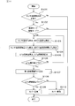
- FIG. 9 is a flowchart of the cover state diagnosis process performed in the cover state diagnosis unit of the exhaust gas sensor in the first embodiment.
- FIG. 10 is a time chart diagram showing the heating control by the heater portion of the exhaust gas sensor and the transition of the temperature of the sensor element in the first embodiment.
- FIG. 11 is a diagram showing the relationship between the ⁇ Tg integrated value and the ⁇ Ts integrated value used in the cover state diagnosis unit of the exhaust gas sensor in the first embodiment by comparing the normal cover product and the abnormal cover product.
- FIG. 12 is a diagram showing the relationship between the ⁇ Tg integrated value and the ⁇ Ts integrated value used in the cover state diagnosis unit of the exhaust gas sensor in the first embodiment and the first diagnostic threshold value.
- FIG. 13 is a diagram showing an outline of the processing procedure in the cover state diagnosis unit of the exhaust gas sensor in the second embodiment.
- FIG. 14 is a flowchart of the cover state diagnosis process performed in the cover state diagnosis unit of the exhaust gas sensor in the second embodiment.
- FIG. 15 is a time chart diagram showing the heating control by the heater portion of the exhaust gas sensor and the transition of the temperature of the sensor element in the second embodiment.
- the exhaust gas sensor S includes a sensor main body S1 and a control device S2, and the sensor main body S1 has a sensor element 1 having a detection unit 2 and a sensor element 1 inside. It has an element cover 3 for accommodating and a heater 4 for heating the sensor element 1 by generating heat when energized.
- the control device S2 includes a heater control unit 5 that controls heating of the sensor element 1 by the heater 4, a sensor temperature detection unit 51 that detects the temperature of the sensor element 1, and a cover state diagnosis unit 6 that diagnoses the state of the element cover 3. have.
- the exhaust gas sensor S is mounted on, for example, the exhaust gas purification device 100 of the vehicle engine ENG as an internal combustion engine.
- the exhaust gas sensor S is attached to the exhaust gas pipe 101 in a state where the sensor main body S1 is held inside the housing 11, and the exhaust gas is introduced into the element cover 3 located in the exhaust gas pipe 101 and is included in the exhaust gas. It is configured to detect a specific component.
- the sensor element 1 has an elongated rectangular parallelepiped shape and extends in the axial direction X of the sensor body S1.
- the vertical direction in FIG. 1 is the axial direction X
- the lower end side thereof is the tip end side of the sensor body S1
- the upper end side is the base end side of the sensor body S1.
- the detection unit 2 is provided at the tip of the sensor element 1 in the axial direction X, and detects a specific component contained in the exhaust gas.
- the specific component is, for example, a particulate matter (hereinafter, appropriately abbreviated as PM) contained in the exhaust gas discharged from the vehicle engine ENG, or a gas component such as NOx.
- PM particulate matter
- the element cover 3 is for protecting the sensor element 1 from toxic substances and condensed water in the exhaust gas, and has gas flow holes 31 and 32 so that the exhaust gas can be introduced or derived into the internal space.
- the sensor element 1 has a built-in heater 4 for heating the sensor element 1 by generating heat when energized (see, for example, FIG. 3), and the heater control unit 5 controls the heating of the sensor element 1 by the heater 4. ..
- the sensor element 1 passes through a sensor control unit (Sensor Control Unit; hereinafter referred to as SCU) 50 including a heater control unit 5 and an electronic control unit (Electronic Control Unit; hereinafter, a vehicle side) including a cover state diagnosis unit 6. It is connected to (referred to as ECU) 60.
- SCU Sensor Control Unit
- ECU electronic Control Unit
- the cover state diagnosis unit 6 diagnoses the state of the element cover 3 based on the sensor temperature Ts detected by the sensor temperature detection unit 51.
- the cover state diagnosis unit 6 is provided with a temperature fluctuation amount calculation unit 61, a temperature fluctuation amount integration unit 62, and an abnormality determination unit 63 for determining a cover abnormality.
- the temperature fluctuation amount calculation unit 61 calculates the fluctuation amount of the sensor temperature Ts (hereinafter, appropriately abbreviated as the sensor temperature fluctuation amount) ⁇ Ts in a predetermined period, and the temperature fluctuation amount integration unit 62 calculates the calculated sensor temperature fluctuation amount. Accumulate ⁇ Ts.
- the abnormality determination unit 63 determines the presence or absence of a cover abnormality based on the comparison result between the fluctuation amount integrated information of the sensor temperature Ts and the diagnostic threshold value (for example, the first diagnostic threshold value TH1).
- the temperature fluctuation amount calculation unit 61 further calculates the fluctuation amount of the exhaust gas temperature Tg (hereinafter, appropriately abbreviated as the exhaust gas temperature fluctuation amount) ⁇ Tg. Further, the temperature fluctuation amount integrating unit 62 further calculates an integrated value of the exhaust gas temperature fluctuation amount ⁇ Tg.
- the first diagnostic threshold TH1 can be set based on the integrated value of the exhaust gas temperature fluctuation amount ⁇ Tg. Specifically, the temperature fluctuation amount integrating unit 62 calculates the integrated value of the sensor temperature fluctuation amount ⁇ Ts as the fluctuation amount integration information of the sensor temperature Ts.
- the abnormality determination unit 63 can determine that there is no cover abnormality when the integrated value of the sensor temperature fluctuation amount ⁇ Ts becomes the first diagnostic threshold value TH1 or more.
- the cover state diagnosis unit 6 further includes a diagnosis possibility determination unit 64 that determines whether or not the cover state diagnosis is possible based on the integrated value of the exhaust gas temperature fluctuation amount ⁇ Tg.
- the diagnosis possibility determination unit 64 can determine that the cover state diagnosis is possible when the integrated value of the exhaust gas temperature fluctuation amount ⁇ Tg becomes a preset specified value T0 or more. In this way, by performing the cover state diagnosis after reaching the integrated amount corresponding to the specified value T0, more accurate diagnosis becomes possible.
- the diagnosis possibility determination unit 64 is at least one of the control state of the heater control unit 5, the state of the sensor temperature detection unit 51, and the operating state of the vehicle engine ENG. It is also possible to determine whether or not the cover state diagnosis is possible based on one.
- the sensor body S1 of the exhaust gas sensor S accommodates the sensor element 1 inside the tubular housing 11, and also has a container-shaped element cover 3 fixed to the tip side of the housing 11 in the axial direction X.
- a tubular air cover 12 fixed to the other end side is provided.
- the housing 11 is attached to, for example, the exhaust gas pipe 101 of the exhaust gas purification device 100 shown in FIG. 4, and the tip end side of the sensor element 1 covered with the element cover 3 is projected in the exhaust gas pipe 101.
- the atmosphere cover 12 covers the proximal end side of the sensor element 1 located outside the exhaust gas pipe 101, and the sensor element 1 and the sensor control unit 50 pass through a lead wire 13 taken out from the proximal end side of the atmospheric cover 12. Is electrically connected.
- the sensor element 1 is, for example, a laminated element having a laminated structure, and the tip surface of the flat rectangular parallelepiped insulating substrate 21 is the detection unit 2.
- a plurality of linear electrodes serving as a pair of detection electrodes 2a and 2b are arranged in the detection unit 2, and a plurality of electrode pairs having different polarities are formed alternately.
- the detection unit 2 is formed by, for example, alternately arranging electrode films to be the detection electrodes 2a and 2b between a plurality of insulating sheets to be the insulating substrate 21 to form a laminated body, and firing and integrating them. It is formed.
- the edge portion of the electrode film, which is at least partially embedded in the insulating substrate 21, is linearly exposed on the tip surface of the insulating substrate 21 to form the detection electrodes 2a and 2b.
- the insulating substrate 21 can be constructed by using an insulating ceramic material such as alumina.
- the PM detection control unit 52 includes, for example, a voltage application circuit for applying a PM detection voltage between the pair of detection electrodes 2a and 2b, and causes PM between the pair of detection electrodes 2a and 2b during a predetermined detection period. Electrostatic collection.
- the element cover 3 has, for example, a double container shape in which the housing 11 side opens, and is composed of an outer cover 3a and an inner cover 3b that are coaxially arranged.
- the outer cover 3a is composed of a tubular body having a substantially constant diameter and a tip surface that closes the tubular body, and a plurality of gas flow holes 31 are formed through the side surface on the tip surface side so that exhaust gas can be introduced or derived from the exhaust gas pipe 101. It has become.
- the inner cover 3b has a gas flow hole 32 penetrating the tip surface thereof to communicate the space inside the inner cover 3b and the space inside the outer cover 3a.
- a plurality of gas flow holes 32 are formed through the side surface of the inner cover 3b on the base end side, and the gas flow holes 32 are provided with a guide portion 33 that is inclined toward the inside of the inner cover 3b. There is.
- the exhaust gas introduced into the outer cover 3a is guided to the proximal end side along the outer surface of the inner cover 3b, and is introduced into the inner cover 3b from the gas flow hole 32.
- the tip of the guide unit 33 is arranged toward the detection unit 2 of the sensor element 1 located on the axis of the inner cover 3b, and the exhaust gas introduced into the inner cover 3b is directed to the detection unit 2 and then the tip surface. It is led out from the gas flow hole 32 of the above and joins the flow of the exhaust gas led out from the outer cover 3a to the outside.
- the gas flow holes 31 and 32 on the front end surface side of the outer cover 3a and the inner cover 3b have, for example, a circular hole shape, and the gas flow holes 32 on the base end side of the inner cover 3b are, for example, elongated holes elongated in the axial direction X. In shape, it is integrally formed with an elongated plate-shaped guide portion 33 formed by cutting out the side surface of the inner cover 3b.
- the shapes of the outer cover 3a and the inner cover 3b and the shapes of the gas flow holes 31 and 32 are not limited to those described above, and may have any configuration. Further, the gas flow hole 32 may not be provided with the guide portion 33, and the number and arrangement of the gas flow holes 31 and 32 can be arbitrarily set. Preferably, if the gas flow holes 31 and 32 are evenly arranged on the entire circumference of the side surface of the outer cover 3a or the inner cover 3b, the configuration does not have directivity with respect to the gas flow.
- the exhaust gas sensor S in this embodiment is applied to the exhaust gas purification device 100 of a vehicle engine (for example, a diesel engine) ENG.
- a housing 11 is attached to the pipe wall of the exhaust gas pipe 101 on the downstream side of the diesel particulate filter (hereinafter abbreviated as DPF) 102, and a half of the element cover 3 side is inside the exhaust gas pipe 101.
- DPF diesel particulate filter
- the exhaust gas sensor S is used as a PM sensor, detects particulate matter leaking from the DPF 102, and transmits a detection signal to the SCU 50.
- a temperature sensor 103 is arranged between the DPF 102 and the sensor body S1 to detect the exhaust gas temperature Tg in the exhaust gas pipe 101 on the downstream side of the DPF 102.
- the detection signal of the temperature sensor 103 is transmitted to the ECU 60 as exhaust gas temperature information.
- the PM detection principle will be described with reference to the schematic diagram shown in FIG.
- a pair of detection electrodes 2a and 2b are arranged to face each other on the surface of the insulating substrate 21 at predetermined intervals, and the pair of detection electrodes 2a and 2b are conductive in the initial state. Absent.
- the PM detection control unit 52 When a predetermined voltage is applied by the PM detection control unit 52 during the PM detection period, the PM is attracted by the electric field generated between the pair of detection electrodes 2a and 2b and gradually deposited.
- the pair of detection electrodes 2a and 2b are electrically connected, the resistance value between the pair of detection electrodes 2a and 2b changes according to the amount of PM collected. Therefore, in the PM detection control unit 52, the pair of detection electrodes The current between 2a and 2b can be detected.
- the heater electrodes forming the heat generating portion 41 of the heater 4 and the heat generating portion 41 are formed in the vicinity of the tip surface where the detection electrodes 2a and 2b are formed.
- a pair of lead portions 42 and 43 for energizing and a detection lead portion 44 are embedded. These lead portions 42, 43, 44 are pulled out to the proximal end side of the sensor element 1 and connected to the heater control portion 5 of the SCU 50 via the lead wire 13 (see, for example, FIG. 1).
- the heater control unit 5 includes, for example, a pulse width modulation circuit that controls the pulse width of the heater drive signal, and controls the amount of electricity supplied to the heat generating unit 41 by the duty ratio of the pulse signal (hereinafter referred to as heater duty).
- the heat generation amount of the heater 4 can be controlled by the heater control unit 5 so as to correspond to the preset control mode of the sensor temperature Ts, and the sensor element 1 can be heated to a desired temperature.
- the detection unit 2 can be heated to a temperature equal to or higher than the combustion temperature of PM, and the collected PM can be burned and removed to return to the initial state.
- the heater control unit 5 variably controls the heater duty so that the sensor temperature Ts detected by the sensor temperature detection unit 51 becomes a temperature according to the control mode. At that time, the sensor temperature detection unit 51 can detect the sensor temperature Ts based on, for example, the resistance value of the heater 4 built in the sensor element 1. Alternatively, the sensor element 1 may be provided with a temperature detecting means such as a thermocouple or a thermistor to detect the sensor temperature Ts. The control mode of the sensor temperature Ts by the SCU 50 will be described later.
- FIG. 6 shows the heater resistance characteristics, and as shown in the upper diagram of FIG. 6 the relationship between the sensor temperature Ts (unit: ° C.) and the heater resistance (unit: ⁇ ), the higher the sensor temperature Ts, the higher the heater resistance. Becomes larger. Therefore, for example, a heater resistance detection circuit is provided in the sensor temperature detection unit 51 to detect the heater resistance from the current flowing through the heat generating unit 41 of the heater 4 when a predetermined voltage is applied, and further, the relationship shown in FIG. Can be used to detect the sensor temperature Ts. The lower figure of FIG. 6 will be described later.
- the PM sensor information includes heater control information such as a control mode and heater duty by the heater control unit 5, sensor temperature information from the sensor temperature detection unit 51, and PM detection information from the PM detection control unit 52.
- the ECU 60 is provided with an operating state detection unit 14 for inputting an intake air amount detected by an air flow meter (not shown) and a detection signal from an engine speed sensor, an accelerator opening sensor, or the like (for example, FIG. 1). reference). Based on these input information, the ECU 60 knows the operating state of the engine ENG and controls the entire vehicle.
- the operating state of the engine ENG also includes exhaust gas information such as the exhaust gas flow velocity in the exhaust gas pipe 101 and regeneration information of the DPF 102 installed in the exhaust gas pipe 101.
- the exhaust gas flow velocity may be a detected value or an estimated value estimated from the operating state of the engine ENG or the like.
- the ECU 60 is provided with a DPF regeneration control unit 15 that controls regeneration of the DPF 102 and a DPF failure diagnosis unit 16 that diagnoses the failure of the DPF 102.
- the DPF regeneration control unit 15 determines whether or not the regeneration of the DPF 102 is necessary based on, for example, the driving state of the vehicle detected by the driving state detection unit 14, and the DPF failure diagnosis unit 16 determines, for example, the PM detection control unit 52. Based on the PM detection information from, it is determined whether or not there is a failure such as a crack in the DPF 102.
- the engine ENG is not limited to a diesel engine, but may be a gasoline engine. In that case, a gasoline particulate filter (ie, GPF) is arranged in place of the DPF 102.
- GPF gasoline particulate filter
- the PM detection information by the PM detection control unit 52 is mainly used for the failure diagnosis of the DPF 102 in the DPF failure diagnosis unit 16 of the ECU 60 described above.
- the PM detection by the exhaust gas sensor S is normally performed, which affects not only the operation of the sensor element 1 but also the operation of the sensor element 1.
- the state of the element cover 3 is also important.
- the exhaust gas sensor S is provided with a cover state diagnosis unit 6 whose outline is shown in FIG. 7, and diagnoses the state of the element cover 3 (hereinafter, appropriately referred to as cover state diagnosis) due to cover clogging or the like. Enables detection of abnormalities.
- the procedure (3) corresponds to the temperature fluctuation amount calculation unit 61
- the procedure (4) corresponds to the temperature fluctuation amount integration unit 62.
- the procedure (6) corresponds to the abnormality determination unit 63.
- the procedures (1) and (5) correspond to the diagnosis possibility determination unit 64, and the sensor temperature detection unit 51 is used in the procedure (2).
- the cover state diagnosis it is possible to use the fluctuation amount integration information of the sensor temperature Ts based on the detection result of the sensor temperature detection unit 51 in the procedure (2).
- the integrated value of the sensor temperature fluctuation amount ⁇ Ts (hereinafter, appropriately referred to as ⁇ Ts integrated value) is used as the fluctuation amount integrated information of the sensor temperature Ts, and is compared with the predetermined first diagnostic threshold TH1.
- the cover state is based on the state of the sensor temperature detection unit 51 and the control state of the heater control unit 5 prior to the calculation of the ⁇ Ts integrated value in the procedures (2) to (4). It is desirable to judge whether or not the diagnosis is possible.
- the state of the sensor temperature detection unit 51 can be determined based on whether or not the temperature detection by the sensor temperature detection unit 51 can be performed, and the control state of the heater control unit 5 is determined based on the control mode of the sensor element 1 by the SCU 50. can do.
- the sensor temperature Ts can be detected normally using the resistance value of the heater 4, and the control mode of the sensor element 1 is a mode in which the energization of the heater 4 is turned off (for example, particulate matter). It can be determined that the cover state diagnosis is possible on the assumption that the temperature detection by the sensor temperature detection unit 51 is possible and the state is suitable for the cover state diagnosis when the sensor temperature detection unit 51 is in the collection mode).
- the cover condition diagnosis cannot be performed because the condition is not suitable for the condition diagnosis. In that case, the temperature detection in step (2) cannot be performed, and the subsequent cover state diagnosis is not performed.
- whether or not the temperature can be detected is determined based on the heater resistance used for detecting the sensor temperature Ts. For example, if the heater resistance changes due to deterioration or the like, the detection accuracy of the sensor temperature Ts using the heater resistance decreases. Therefore, the normal range of the heater resistance is set in advance with the resistance thresholds Rth1 and Rth2 as the upper and lower limit values. When the detected heater resistance is in the normal range (that is, Rth1 ⁇ heater resistance ⁇ Rth2), it can be determined that the heater 4 is in the normal state.
- the control modes of the sensor element 1 by the SCU 50 are water- and liquid-phase poisoning-resistant mode, sensor regeneration mode, cooling mode, collection mode, and solid-phase poisoning resistance when the engine ENG is started. Transition in the order of modes. For example, in the water- and liquid-phase poisoning-resistant mode, the water droplets and the like adhering to the sensor element 1 are maintained at a temperature at which they can evaporate at the time of low-temperature start-up. The temperature is raised to a combustible temperature and maintained. Next, in the cooling mode, the energization of the heater 4 is stopped, the sensor element 1 cools to the same level as the exhaust gas temperature Tg in the exhaust gas pipe 101, and then the mode shifts to the collection mode. After that, in the solid phase poisoning resistant mode, the solid phase poisoning substance adhering to the sensor element 1 can be maintained at a temperature at which it can be removed.
- the sensor temperature detection unit 51 detects the sensor temperature Ts and calculates the sensor temperature fluctuation amount ⁇ Ts in the procedures (2) to (4).
- the calculation of the ⁇ Ts integrated value is sequentially performed.
- the sensor temperature fluctuation amount ⁇ Ts may be the fluctuation amount of the sensor temperature Ts per unit time, for example, the difference value (absolute value) between the previous value and the current value of the sensor temperature Ts detected in a fixed cycle. it can.
- it can be a fluctuation amount of the sensor temperature Ts detected every unit time, for example, a difference value (absolute value) between the sensor temperature Ts detected at a fixed cycle and the reference temperature.
- the exhaust gas temperature fluctuation amount ⁇ Tg (hereinafter, appropriately referred to as ⁇ Tg integrated value) as the fluctuation amount integrated information for the exhaust gas temperature Tg in addition to the sensor temperature Ts.
- the exhaust gas temperature Tg can be detected by using the temperature sensor 103 in the same procedure as the sensor temperature Ts, the exhaust gas temperature fluctuation amount ⁇ Tg can be calculated, and the ⁇ Tg integrated value can be calculated in sequence.
- the exhaust gas temperature fluctuation amount ⁇ Tg can be calculated in the same manner as the sensor temperature fluctuation amount ⁇ Ts.
- the cover state diagnosis unit 6 determines whether or not the cover state diagnosis is possible based on the calculated ⁇ Tg integrated value in the procedure (5) prior to the determination of the cover abnormality.
- the cover state diagnosis unit 6 determines whether or not the cover state diagnosis is possible based on the calculated ⁇ Tg integrated value in the procedure (5) prior to the determination of the cover abnormality.
- the cover state diagnosis unit 6 determines whether or not there is a cover abnormality based on the calculated ⁇ Ts integrated value in the procedure (6).
- the variable first diagnostic threshold TH1 is calculated based on the ⁇ Tg integrated value and compared with the ⁇ Ts integrated value. If the ⁇ Ts integrated value reaches the first diagnostic threshold TH1, it can be determined that the cover is normal (no cover abnormality), and if it does not reach the first diagnostic threshold TH1, it can be determined that the cover is abnormal.
- Step S101 to S102 of FIG. 9 correspond to the procedure (1) of FIG. 7, and steps S103 to S105 correspond to the procedures (2) to (4) of FIG. 7, respectively.
- Step S106 corresponds to the procedure (5) of FIG. 7, and steps S107 to S108 correspond to the procedure (6) of FIG. 7.
- step S101 it is determined whether or not the sensor temperature detection unit 51 is in a state in which it can normally operate. Specifically, the heater control unit 5 detects the heater resistance from the current flowing when a predetermined voltage is applied to the heater 4, and the detected heater resistance is within the normal range based on the relationship shown in the lower figure of FIG. (That is, Rth1 ⁇ heater resistance ⁇ Rth2?).
- the heater 4 is made of a conductive material containing a noble metal or the like, and when the heater 4 is repeatedly heated continuously or intermittently with the operation of the sensor element 1, due to aggregation of the noble metal material or the like, the heater 4 is formed.
- the heater resistance changes. When this change becomes large, the heater 4 does not function normally, and the accuracy of the cover state diagnosis also deteriorates. Therefore, for example, the heater resistance in the initial state is measured in advance, and the resistance threshold value Rth1 based on this initial resistance is set as the lower limit value in the normal range. Further, with respect to this resistance threshold value Rth1, the resistance threshold value Rth2, which is the upper limit value of the normal range, can be set in consideration of the amount of change in the heater resistance due to aged deterioration or the like.
- step S101 it is determined that the sensor temperature detection unit 51 for detecting the sensor temperature Ts is in a state in which it can operate normally, and the process proceeds to step S102. If a negative determination is made, it is determined that the sensor temperature detection unit 51 does not operate normally, this process is temporarily terminated, and the cover state diagnosis is not performed.
- step S102 it is determined whether or not the control mode of the sensor temperature Ts by the SCU 50 is the collection mode. If the affirmative determination is made in step S102, it is determined that the heater 4 is in the off state, is not affected by the heating by the heater 4, and is suitable for the cover state diagnosis, and the process proceeds to step S103. When the negative determination in step S102 is made, it is determined that the control mode is other than the collection mode and the state is not suitable for the cover state diagnosis using the sensor temperature detection unit 51, and this process is terminated to cover. No condition diagnosis is performed.
- the control mode of the sensor element 1 by the SCU 50 transitions to the water-resistant / liquid-phase poisoning mode and the sensor regeneration mode when the engine ENG is started, and the heater control unit 5 shifts to the heater 4. It is energized and controlled to a predetermined temperature. After that, in the cooling mode, the heater 4 is turned off and the mode shifts to the collection mode. In the collection mode after cooling, the sensor element 1 is lowered to the same level as the exhaust gas temperature Tg, and the sensor temperature Ts also fluctuates as the exhaust gas temperature Tg fluctuates.
- the control mode of the sensor element 1 by the SCU 50 is the collection mode
- the heater 4 is in the off state
- the sensor temperature Ts is equivalent to the exhaust gas temperature Tg
- the cover state diagnosis unit 6 can determine an abnormality. It is in a state.
- the reliability of the cover state diagnosis can be improved by determining in advance whether or not the cover state diagnosis can be performed based on the heater state.
- step S103 the sensor temperature Ts detected by the sensor temperature detection unit 51 is taken in, and the exhaust gas temperature Tg detected by the temperature sensor 103 is taken in.
- step S104 the sensor temperature fluctuation amount ⁇ Ts and the exhaust gas temperature fluctuation amount ⁇ Tg are calculated, respectively.
- the absolute value of the difference value is calculated from the previously detected sensor temperature Ts and exhaust gas temperature Tg and the sensor temperature Ts and exhaust gas temperature Tg detected this time, and the sensor temperature fluctuates.
- the amount ⁇ Ts and the exhaust gas temperature fluctuation amount ⁇ Tg can be set.
- ⁇ Ts absolute value of [previous Ts-current Ts]
- ⁇ Tg absolute value of [previous Tg-current Tg]
- step S105 calculate the ⁇ Ts integrated value and the ⁇ Tg integrated value.
- the sensor temperature fluctuation amount ⁇ Ts and the exhaust gas temperature fluctuation amount ⁇ Tg calculated this time are added to the previous ⁇ Ts integrated value or ⁇ Tg integrated value, and the current ⁇ Ts integrated value and ⁇ Tg integrated value are added.
- the integrated value calculated this time is a value obtained by adding all the temperature fluctuation amounts (absolute values) up to this time.
- ⁇ Ts integrated value ⁇ Ts + [previous ⁇ Ts integrated value]
- ⁇ Tg integrated value ⁇ Tg + [previous ⁇ Tg integrated value]
- the process proceeds to step S106 and thereafter, and the cover state diagnosis is performed.
- the relationship between the exhaust gas temperature Tg and the sensor temperature Ts changes depending on the state of the element cover 3 in the operating state in which the engine speed and the exhaust gas flow velocity fluctuate.
- the sensor temperature Ts fluctuates more when the cover is normal than when the cover is abnormal, and the ⁇ Ts integrated value when the cover is normal is larger than the ⁇ Ts integrated value when the cover is abnormal. large.
- the ⁇ Ts integrated value when the cover is normal changes along the ⁇ Tg integrated value
- the ⁇ Ts integrated value when the cover is abnormal deviates from the ⁇ Tg integrated value with the passage of time, and the time As the lapse of time, the difference between the ⁇ Ts integrated value when the cover is normal and when the cover is abnormal becomes larger.
- FIG. 10 shows the relationship between the fluctuations of the exhaust gas temperature Tg and the sensor temperature Ts in the WHTC (World Harmonized Transient Cycle) mode, which is the exhaust gas test mode for diesel engines, and their integrated values. is there.
- WHTC World Harmonized Transient Cycle
- the ⁇ Tg integrated value and the ⁇ Ts integrated value are the total length of the trajectory of the characteristic line indicating the temperature change of the sensor temperature Ts after the integration is started.
- the gas flow holes 31 and 32 are open, so that the exhaust gas that has passed through the gas flow holes 31 and 32 easily hits the surface of the sensor element 1. Therefore, it is easily affected by the fluctuation of the exhaust gas temperature Tg, and the fluctuation amount of the sensor temperature Ts becomes large. Further, the sensor temperature Ts also fluctuates due to the fluctuation of the exhaust gas flow velocity. For example, when the exhaust gas flow velocity is high, the change of the exhaust gas temperature Tg is easily transmitted to the sensor element 1, and the sensor temperature Ts is higher than when it is low. The amount of fluctuation of is larger.
- the element cover 3 has an abnormality such as a cover clogging and the gas flow holes 31 and 32 are closed, it becomes difficult for the exhaust gas to hit the surface of the sensor element 1. Therefore, it is not easily affected by the fluctuation of the exhaust gas temperature Tg and the fluctuation of the exhaust gas flow velocity, and the fluctuation amount of the sensor temperature Ts becomes small. Therefore, although the sensor temperature Ts at the time of such a cover abnormality changes so as to follow an increase or decrease of the exhaust gas temperature Tg, for example, the sensor fluctuation amount ⁇ Ts is smaller than that at the time of normal cover. Therefore, using this relationship, it is possible to determine the presence or absence of a cover abnormality due to cover clogging or the like.
- the specified value T0 can be distinguished from each other within a range in which the ⁇ Ts integrated value (lower limit value including variation) when the cover is normal and the ⁇ Ts integrated value (upper limit value including variation) when the cover is abnormal do not overlap. It can be set as appropriate.
- the first diagnostic threshold TH1 for distinguishing between the normal cover and the abnormal cover according to the magnitude of the ⁇ Tg integrated value.
- the first diagnostic threshold TH1 can be, for example, the median value of the ⁇ Ts integrated value (lower limit value including variation) when the cover is normal and the ⁇ Ts integrated value (upper limit value including variation) when the cover is abnormal.
- the settings are as shown in Table 1.
- step S106 it is determined whether or not the ⁇ Tg integrated value calculated in step S105 is equal to or greater than the specified value T0 (that is, ⁇ Tg integrated value ⁇ T0?) Using the relationship shown in FIG. If the affirmative determination is made in step S106, it is determined that the integrated amount of the exhaust gas temperature fluctuation amount ⁇ Tg has reached the specified value T0 at which the cover state diagnosis is possible, and the process proceeds to step S107. If the negative determination in step S106 is made, the process returns to step S103 and the subsequent steps are repeated.
- the first diagnostic threshold TH1 is calculated from the ⁇ Tg integrated value calculated in step S105 using the relationship shown in FIG.
- the cover state diagnosis unit 6 stores the threshold map or the calculation formula based on the relationship shown in Table 1 in advance to correspond to the ⁇ Tg integrated value at the time of diagnosis of the cover state for the cover state diagnosis.
- the first diagnostic threshold TH1 can be calculated appropriately.
- step S108 determines whether or not the ⁇ Ts integrated value calculated in step S105 is equal to or higher than the first diagnostic threshold TH1 calculated in S106 (that is, ⁇ Ts integrated value ⁇ TH1?). If the affirmative determination is made in step S108, the process proceeds to step S109 to determine that the cover is normal, and if the negative determination is made, the process proceeds to step S110 to determine that the cover is abnormal. After that, this process ends.
- the first diagnostic threshold TH1 is 86 ° C. If the element cover 3 is in a normal state, the ⁇ Ts integrated value including the variation is about 95 to 125 ° C., which is larger than the first diagnostic threshold TH1, and thus a normal determination is made. On the other hand, when the element cover 3 is not in a normal state, the ⁇ Ts integrated value including the variation is about 47 to 77 ° C., which is smaller than the first diagnostic threshold TH1, and thus an abnormality is determined.
- the fluctuation amount calculation unit 61 which integrates the fluctuation amount of the sensor temperature Ts detected by the temperature detection unit 51, while integrating the fluctuation amount of the exhaust gas temperature Tg, A fluctuation amount integrating unit 62 is provided, and the abnormality determining unit 63 reliably determines whether the element cover 3 is in a normal state or an abnormal state by comparing the first diagnostic threshold TH1 corresponding to the ⁇ Tg integrated value with the ⁇ Ts integrated value. can do.
- the integrated amount of the exhaust gas temperature fluctuation amount ⁇ Tg becomes a predetermined specified value T0 or more and the state of the heater 4 is in a state suitable for temperature detection.
- the procedure (3) corresponds to the temperature fluctuation amount calculation unit 61
- the procedure (4) corresponds to the temperature fluctuation amount integration unit 62
- Procedure (6) corresponds to the abnormality determination unit 63
- the procedures (1) and (5) correspond to the diagnosis possibility determination unit 64
- the sensor temperature detection unit 51 is used in the procedure (2).
- the processing procedures (2) to (5) are the same as those in the first embodiment, and the description thereof will be omitted.
- the state of the sensor temperature detection unit 51 and the heater control unit 5 are used when determining whether or not the cover state diagnosis is possible prior to the calculation of the ⁇ Ts integrated value in the procedures (2) to (4).
- the exhaust gas flow velocity is detected as the state of the exhaust gas in the exhaust gas pipe 101, and it is determined whether or not the change in the exhaust gas flow velocity per unit time is a predetermined specified value V0 or more (for example, 1 m / s). To do.
- the temperature detection may be enabled only when the change in the exhaust gas flow velocity is large. If the change in the exhaust gas flow velocity is small, the following procedure is not performed.
- the sensor temperature Ts is detected, the sensor temperature fluctuation amount ⁇ Ts is calculated, and the ⁇ Ts integrated value is calculated in the procedures (2) to (4) in the same manner as in the first embodiment.
- the calculation is carried out sequentially.
- the exhaust gas temperature Tg is detected, the exhaust gas temperature fluctuation amount ⁇ Tg is calculated, and the ⁇ Tg integrated value is calculated.
- the exhaust gas temperature Tg is determined by comparing with the preset specified value T0 based on the calculated ⁇ Tg integrated value to determine whether or not the cover state diagnosis is possible. Determine if the variability has reached an integrated amount sufficient for diagnosis.
- the cover state diagnosis unit 6 determines whether or not there is a cover abnormality based on the calculated ⁇ Ts integrated value in the procedure (6).
- the first diagnostic threshold TH1 which is a variable value is calculated based on the ⁇ Tg integrated value and compared with the ⁇ Ts integrated value.
- the ratio based on the ⁇ Tg integrated value may be calculated, and a map or the like for calculating the diagnostic threshold value for the cover state diagnosis can be unnecessary. If the ⁇ Ts integrated value reaches the second diagnostic threshold value TH2, it can be determined that the cover is normal, and if it does not reach the second diagnostic threshold value TH2, it can be determined that the cover is abnormal.
- Step S201 to S203 of FIG. 14 correspond to the procedure (1) of FIG. 13, and steps S204 to S206 correspond to the procedures (2) to (4) of FIG. 13, respectively.
- Step S207 corresponds to the procedure (5) of FIG. 13, and steps S208 to S209 correspond to the procedure (6) of FIG.
- step S201 the sensor temperature detection unit 51 determines whether or not it is in a state in which it can operate normally, and if a positive judgment is made, it is determined.
- Step S202 it is determined whether or not the control mode of the sensor temperature Ts by the SCU 50 is the collection mode. Steps S201 to S202 are the same as steps S101 to S102 in the first embodiment, and the description thereof will be omitted.
- step S203 the exhaust gas flow velocity detected by the operating state detection unit 14 is further taken in, and it is determined whether or not the change in the exhaust gas flow velocity from the previous time is a specified value V0 or more (for example, 1 m / s) (that is,). , Exhaust gas flow velocity change ⁇ V0?). If the affirmative determination is made in step S203, it is determined that the exhaust gas flow velocity is in a state suitable for the cover state diagnosis, and the process proceeds to step S204. If any of steps S201 to S203 is negatively determined, this process ends.
- step S204 the sensor temperature Ts detected by the sensor temperature detection unit 51 and the exhaust gas temperature Tg detected by the temperature sensor 103 are taken in, and then the process proceeds to step S205 to obtain the sensor temperature fluctuation amount ⁇ Ts and the exhaust gas temperature fluctuation amount ⁇ Tg. , Calculate respectively. Further, the process proceeds to step S206 to calculate the ⁇ Ts integrated value and the ⁇ Tg integrated value.
- step S207 it is determined whether or not the calculated ⁇ Tg integrated value is equal to or greater than the specified value T0 (that is, ⁇ Tg integrated value ⁇ T0?) In the same manner as in step S106 in the first embodiment. If the affirmative determination is made in step S207, the process proceeds to step S208, and if the negative determination is made, the process returns to step S204 and the subsequent steps are repeated.
- step S208 the ratio of the ⁇ Ts integrated value and the ⁇ Tg integrated value is calculated, and the process proceeds to step S209.
- step S209 it is determined whether or not the calculated ratio is equal to or higher than the preset second diagnostic threshold TH2 (that is, ratio ⁇ TH2?). If the affirmative determination is made in step S209, the process proceeds to step S210 to determine that the cover is normal, and if the negative determination is made, the process proceeds to step S211 to determine that the cover is abnormal. After that, this process ends.
- the preset second diagnostic threshold TH2 that is, ratio ⁇ TH2?
- FIG. 15 shows the ratios obtained from the relationship between the ⁇ Ts integrated value and the ⁇ Tg integrated value in the predetermined traveling mode shown in FIG. 12 and compared between the normal cover and the abnormal cover. ..
- temperature detection becomes possible, and the lower limit of the ratio when the cover is normal and the upper limit of the ratio when the cover is abnormal do not overlap each other in consideration of variation, and both fluctuate after a certain period of time. As it becomes smaller, the difference in ratio becomes larger.
- the cover state diagnosis becomes possible. ..
- the second diagnostic threshold TH2 when the second diagnostic threshold TH2 is set to 0.5, the calculated ratio (for example, 0.7) is higher than the second diagnostic threshold TH2 if there is no cover clogging or the like. It becomes a large value, and the cover is diagnosed as normal.
- the calculated ratio for example, 0.3
- the cover abnormality is diagnosed.
- the fluctuation amount calculation unit 61 that integrates the fluctuation amount of the sensor temperature Ts detected by the temperature detection unit 51 while integrating the fluctuation amount of the exhaust gas temperature Tg.
- the fluctuation amount integrating unit 62 is provided, and the abnormality determination unit 63 compares the ratio of the ⁇ Ts integrated value to the ⁇ Tg integrated value with the second diagnostic threshold TH2 to ensure whether the element cover 3 is in the normal state or the abnormal state. Can be judged.
- the integrated amount of the exhaust gas temperature fluctuation amount ⁇ Tg becomes a predetermined specified value T0 or more, and the state of the heater 4 and the exhaust gas flow velocity are in a state suitable for temperature detection.
- the present disclosure is not limited to each of the above embodiments, and can be applied to various embodiments without departing from the gist thereof.
- the exhaust gas sensor S can be used not only for the PM sensor but also for a gas sensor such as a NOx sensor. Even when used for such a gas sensor, the state of the element cover 3 can be diagnosed in the same manner by providing the cover state diagnosis unit 6.
- the engine including the DPF 102 to the exhaust gas purification system is shown, but the system configuration including the engine can be changed as appropriate. Further, it can be used not only for vehicles but also for various purposes, and the structures of the exhaust gas sensor S and the sensor element 1 can be appropriately changed.
Abstract
An exhaust gas sensor (S) for detecting a specific component included in an exhaust gas is provided with: a sensor element (1) provided with a detection unit (2); an element cover (3) that houses thereinside the sensor element (1) and has gas distribution holes (31, 32); a heater (4) that heats the sensor element (1); a heater control unit (5); and a cover state diagnosis unit (6) that diagnoses the state of the element cover (1) on the basis of a sensor temperature (Ts) detected by a sensor temperature detection unit (51). The cover state diagnosis unit (6) has a temperature fluctuation amount calculation unit (61) that calculates a sensor temperature fluctuation amount (ΔTs), a temperature fluctuation amount integration unit (62) that integrates the sensor temperature fluctuation amount (ΔTs), and an abnormality determination unit (63) that determines whether there is a cover abnormality on the basis of a comparison result of the fluctuation amount integration information of the sensor temperature (Ts) with diagnostic threshold values (TH1, TH2).
Description
本出願は、2019年5月29日に出願された特許出願番号2019-100208号に基づくもので、ここにその記載内容を援用する。
This application is based on Patent Application No. 2019-100208 filed on May 29, 2019, and the contents of the description are incorporated herein by reference.
本開示は、排ガスに含まれる成分を検出するための排ガスセンサに関する。
The present disclosure relates to an exhaust gas sensor for detecting components contained in exhaust gas.
車両用エンジン等からの排ガスに含まれる特定のガス成分(例えば、NOx)や粒子状物質(すなわち、Particulate Matter;以下、適宜PMと称する)等を検出するために排ガスセンサが用いられる。排ガスセンサは、通常、ハウジングに支持されるセンサ素子の先端部が、素子カバーに収容された状態で、排ガス通路に位置するように取り付けられる。
An exhaust gas sensor is used to detect a specific gas component (for example, NOx) or particulate matter (that is, Particulate Matter; hereinafter, appropriately referred to as PM) contained in the exhaust gas from a vehicle engine or the like. The exhaust gas sensor is usually attached so that the tip of the sensor element supported by the housing is located in the exhaust gas passage in a state of being housed in the element cover.
近年、車両用エンジンの排ガス規制が厳しくなっており、排ガスセンサについても、その故障を検出することが要求されている。例えば、粒子状物質を捕集するパティキュレートフィルタを含む排ガス浄化システムには、PMセンサが設けられて、パティキュレートフィルタの破損時等に漏れ出る粒子状物質を検出するようになっているが、PMセンサが正常に動作しないと誤検出が生じるおそれがある。そこで、システムの信頼性を確保するために、PMセンサそのものの異常の有無を検出することが必要となっている。
In recent years, exhaust gas regulations for vehicle engines have become stricter, and exhaust gas sensors are also required to detect their failures. For example, an exhaust gas purification system including a particulate filter that collects particulate matter is provided with a PM sensor to detect particulate matter that leaks when the particulate filter is damaged. If the PM sensor does not operate normally, erroneous detection may occur. Therefore, in order to ensure the reliability of the system, it is necessary to detect the presence or absence of abnormality in the PM sensor itself.
また、センサ機能を低下させる要因の1つに、素子カバーの異常があり、例えば、素子カバーの流通孔が塞がれるカバー詰まりや素子カバーの脱落等が生じると、センサ素子へ導入される排ガスの状態が変化して、正常なセンサ出力が得られなくなる。これに対して、センサ素子を加熱するためのヒータを利用して、カバー異常を検出する手段を設けたものがある。例えば、特許文献1には、ヒータによるセンサ再生モード時のヒータ出力電圧を検出し、正常範囲から外れた場合に、故障と判定する診断用モジュールを備えたシステムが提案されている。
Further, one of the factors that deteriorate the sensor function is an abnormality of the element cover. For example, when the cover is clogged or the element cover is dropped, the exhaust gas introduced into the sensor element is exhausted. The state of is changed, and normal sensor output cannot be obtained. On the other hand, there is a device provided with a means for detecting a cover abnormality by using a heater for heating the sensor element. For example, Patent Document 1 proposes a system including a diagnostic module that detects a heater output voltage in a sensor reproduction mode by a heater and determines that the voltage is out of the normal range.
例えば、素子カバーの流通孔が塞がれた状態では、塞がれていない正常状態よりもセンサ素子へのガス当たりが弱くなる。そのために、センサ再生モードにおいて、規定の再生温度まで加熱するのに必要なヒータ電力は低減する。この関係を利用して、特許文献1のシステムでは、検出されるヒータ出力電圧が、正常時の電圧値よりも低い所定の閾値以下であるときに、故障と診断している。しかしながら、このシステムでは、ヒータ機能が正常であることが前提となり、例えば、ヒータに経年変化による劣化等が生じると、加熱に必要なヒータ電力が変動する。すなわち、同じ再生温度となるように加熱しても、劣化状態によりヒータ出力電圧の検出値が変化するために、判定精度が低下して、誤診断につながるおそれがある。
For example, when the flow hole of the element cover is closed, the gas contact with the sensor element is weaker than in the normal state where the element cover is not closed. Therefore, in the sensor regeneration mode, the heater power required to heat to the specified regeneration temperature is reduced. Utilizing this relationship, the system of Patent Document 1 diagnoses a failure when the detected heater output voltage is equal to or less than a predetermined threshold value lower than the normal voltage value. However, in this system, it is premised that the heater function is normal, and for example, if the heater deteriorates due to aging, the heater power required for heating fluctuates. That is, even if the heating is performed so as to have the same regeneration temperature, the detection value of the heater output voltage changes depending on the deterioration state, so that the determination accuracy may decrease, leading to a false diagnosis.
本開示の目的は、センサ素子を保護する素子カバーの状態診断を精度よく実施可能として、より信頼性の高い排ガスセンサを提供しようとするものである。
The object of the present disclosure is to provide a more reliable exhaust gas sensor by making it possible to accurately diagnose the state of the element cover that protects the sensor element.
本開示の一態様は、
内燃機関の排ガスに含まれる特定成分を検出する排ガスセンサであって、
上記特定成分の検出部を備えるセンサ素子と、
上記センサ素子を内側に収容し、上記検出部に排ガスを導入又は導出するためのガス流通孔を有する素子カバーと、
通電により発熱して上記センサ素子を加熱するヒータと、
上記ヒータによる上記センサ素子の加熱を制御するヒータ制御部と、
上記センサ素子の温度を検出するセンサ温度検出部と、
上記センサ温度検出部により検出されるセンサ温度に基づいて、上記素子カバーの状態を診断するカバー状態診断部と、を有しており、
上記カバー状態診断部は、上記センサ温度の変動量を算出する温度変動量算出部と、上記センサ温度の変動量を積算する温度変動量積算部と、上記温度変動量積算部による上記センサ温度の変動量積算情報と診断閾値との比較結果に基づいて、カバー異常の判定を行う、異常判定部とを有する、排ガスセンサにある。 One aspect of the disclosure is
An exhaust gas sensor that detects specific components contained in the exhaust gas of an internal combustion engine.
A sensor element having a detection unit for the specific component and
An element cover that houses the sensor element inside and has a gas flow hole for introducing or deriving exhaust gas to the detection unit.
A heater that generates heat when energized to heat the sensor element,
A heater control unit that controls the heating of the sensor element by the heater, and
A sensor temperature detector that detects the temperature of the sensor element,
It has a cover state diagnosis unit that diagnoses the state of the element cover based on the sensor temperature detected by the sensor temperature detection unit.
The cover state diagnosis unit includes a temperature fluctuation amount calculation unit that calculates the fluctuation amount of the sensor temperature, a temperature fluctuation amount integration unit that integrates the fluctuation amount of the sensor temperature, and the sensor temperature integration unit by the temperature fluctuation amount integration unit. The exhaust gas sensor has an abnormality determination unit that determines a cover abnormality based on a comparison result between the fluctuation amount integration information and the diagnostic threshold value.
上記排ガスセンサにおいて、カバー状態診断部は、センサ温度検出部により検出されるセンサ温度の変動量を算出し、それを積算した変動量積算情報を用いて、診断を行う。素子カバーが正常な状態では、ガス流通孔を通過する排ガスにセンサ素子が晒される状態にあり、排ガス温度が変動すると、それに追従してセンサ温度も同様に変動する。一方、素子カバーに異常があり、例えば、ガス流通孔に詰まりが生じて排ガスにセンサ素子が晒されない状態では、排ガス温度の影響を受けにくくなるため、センサ温度の変動量は、正常時よりも小さくなる。
In the exhaust gas sensor, the cover state diagnosis unit calculates the fluctuation amount of the sensor temperature detected by the sensor temperature detection unit, and makes a diagnosis using the fluctuation amount integration information obtained by integrating the fluctuation amount. In the normal state of the element cover, the sensor element is exposed to the exhaust gas passing through the gas flow hole, and when the exhaust gas temperature fluctuates, the sensor temperature also fluctuates accordingly. On the other hand, if there is an abnormality in the element cover, for example, the gas flow hole is clogged and the sensor element is not exposed to the exhaust gas, it is less affected by the exhaust gas temperature, so the fluctuation amount of the sensor temperature is larger than that in the normal state. It becomes smaller.
そこで、センサ温度の変動量積算情報を指標として、診断閾値と比較することで、素子カバーの異常の診断を実施する。このとき、個々の変動量の差は小さいものの、変動量を積算することで、正常時と異常時との差が大きくなり、診断閾値による区別が容易になる。したがって、従来のように、診断に際して、ヒータ制御情報を用いる必要がないので、ヒータ劣化等の影響を受けることなく、素子カバーの状態を精度よく判定することができる。
Therefore, the abnormality of the element cover is diagnosed by comparing it with the diagnostic threshold value using the sensor temperature fluctuation amount integrated information as an index. At this time, although the difference between the individual fluctuation amounts is small, by integrating the fluctuation amounts, the difference between the normal time and the abnormal time becomes large, and it becomes easy to distinguish by the diagnostic threshold value. Therefore, unlike the conventional case, it is not necessary to use the heater control information in the diagnosis, so that the state of the element cover can be accurately determined without being affected by the deterioration of the heater or the like.
以上のごとく、上記態様によれば、センサ素子を保護する素子カバーの状態診断を精度よく実施可能として、より信頼性の高い排ガスセンサを提供することができる。
As described above, according to the above aspect, it is possible to accurately diagnose the state of the element cover that protects the sensor element, and to provide a more reliable exhaust gas sensor.
本開示についての上記目的及びその他の目的、特徴や利点は、添付の図面を参照しながら下記の詳細な記述により、より明確になる。その図面は、
図1は、実施形態1における、排ガスセンサの全体構成図であり、
図2は、実施形態1における、排ガスセンサのセンサ本体の要部拡大断面図であり、
図3は、実施形態1における、排ガスセンサのセンサ素子の要部拡大斜視図であり、
図4は、実施形態1における、排ガスセンサを含む排ガス浄化システムの全体構成図であり、
図5は、実施形態1における、センサ素子の動作を説明するための模式的な断面図であり、
図6は、実施形態1における、センサ素子のセンサ温度とヒータ抵抗の関係の一例を示す図であり、
図7は、実施形態1における、排ガスセンサのカバー状態診断部における処理手順の概要を示す図であり、
図8は、実施形態1における、排ガスセンサのセンサ素子の制御モードとセンサ温度との関係を示す図であり、
図9は、実施形態1における、排ガスセンサのカバー状態診断部において実施されるカバー状態診断処理のフローチャート図であり、
図10は、実施形態1における、排ガスセンサのヒータ部による加熱制御とセンサ素子の温度の推移を示すタイムチャート図であり、
図11は、実施形態1における、排ガスセンサのカバー状態診断部において用いられるΔTg積算値とΔTs積算値との関係を、カバー正常品とカバー異常品とで比較して示す図であり、
図12は、実施形態1における、排ガスセンサのカバー状態診断部において用いられるΔTg積算値及びΔTs積算値と、第1診断閾値との関係を示す図であり、
図13は、実施形態2における、排ガスセンサのカバー状態診断部における処理手順の概要を示す図であり、
図14は、実施形態2における、排ガスセンサのカバー状態診断部において実施されるカバー状態診断処理のフローチャート図であり、
図15は、実施形態2における、排ガスセンサのヒータ部による加熱制御とセンサ素子の温度の推移を示すタイムチャート図である。
The above objectives and other objectives, features and advantages of the present disclosure will be clarified by the following detailed description with reference to the accompanying drawings. The drawing is
FIG. 1 is an overall configuration diagram of an exhaust gas sensor according to the first embodiment. FIG. 2 is an enlarged cross-sectional view of a main part of the sensor body of the exhaust gas sensor according to the first embodiment. FIG. 3 is an enlarged perspective view of a main part of the sensor element of the exhaust gas sensor according to the first embodiment. FIG. 4 is an overall configuration diagram of an exhaust gas purification system including an exhaust gas sensor according to the first embodiment. FIG. 5 is a schematic cross-sectional view for explaining the operation of the sensor element in the first embodiment. FIG. 6 is a diagram showing an example of the relationship between the sensor temperature of the sensor element and the heater resistance in the first embodiment. FIG. 7 is a diagram showing an outline of the processing procedure in the cover state diagnosis unit of the exhaust gas sensor in the first embodiment. FIG. 8 is a diagram showing the relationship between the control mode of the sensor element of the exhaust gas sensor and the sensor temperature in the first embodiment. FIG. 9 is a flowchart of the cover state diagnosis process performed in the cover state diagnosis unit of the exhaust gas sensor in the first embodiment. FIG. 10 is a time chart diagram showing the heating control by the heater portion of the exhaust gas sensor and the transition of the temperature of the sensor element in the first embodiment. FIG. 11 is a diagram showing the relationship between the ΔTg integrated value and the ΔTs integrated value used in the cover state diagnosis unit of the exhaust gas sensor in the first embodiment by comparing the normal cover product and the abnormal cover product. FIG. 12 is a diagram showing the relationship between the ΔTg integrated value and the ΔTs integrated value used in the cover state diagnosis unit of the exhaust gas sensor in the first embodiment and the first diagnostic threshold value. FIG. 13 is a diagram showing an outline of the processing procedure in the cover state diagnosis unit of the exhaust gas sensor in the second embodiment. FIG. 14 is a flowchart of the cover state diagnosis process performed in the cover state diagnosis unit of the exhaust gas sensor in the second embodiment. FIG. 15 is a time chart diagram showing the heating control by the heater portion of the exhaust gas sensor and the transition of the temperature of the sensor element in the second embodiment.
(実施形態1)
排ガスセンサに係る実施形態について、図1~図12を参照して説明する。
図1~図3に示すように、排ガスセンサSは、センサ本体S1と制御装置S2とを備えて構成され、センサ本体S1は、検出部2を備えるセンサ素子1と、センサ素子1を内側に収容する素子カバー3と、通電により発熱してセンサ素子1を加熱するヒータ4とを有している。制御装置S2は、ヒータ4によるセンサ素子1の加熱を制御するヒータ制御部5と、センサ素子1の温度を検出するセンサ温度検出部51と、素子カバー3の状態を診断するカバー状態診断部6を有している。 (Embodiment 1)
An embodiment relating to the exhaust gas sensor will be described with reference to FIGS. 1 to 12.
As shown in FIGS. 1 to 3, the exhaust gas sensor S includes a sensor main body S1 and a control device S2, and the sensor main body S1 has asensor element 1 having a detection unit 2 and a sensor element 1 inside. It has an element cover 3 for accommodating and a heater 4 for heating the sensor element 1 by generating heat when energized. The control device S2 includes a heater control unit 5 that controls heating of the sensor element 1 by the heater 4, a sensor temperature detection unit 51 that detects the temperature of the sensor element 1, and a cover state diagnosis unit 6 that diagnoses the state of the element cover 3. have.
排ガスセンサに係る実施形態について、図1~図12を参照して説明する。
図1~図3に示すように、排ガスセンサSは、センサ本体S1と制御装置S2とを備えて構成され、センサ本体S1は、検出部2を備えるセンサ素子1と、センサ素子1を内側に収容する素子カバー3と、通電により発熱してセンサ素子1を加熱するヒータ4とを有している。制御装置S2は、ヒータ4によるセンサ素子1の加熱を制御するヒータ制御部5と、センサ素子1の温度を検出するセンサ温度検出部51と、素子カバー3の状態を診断するカバー状態診断部6を有している。 (Embodiment 1)
An embodiment relating to the exhaust gas sensor will be described with reference to FIGS. 1 to 12.
As shown in FIGS. 1 to 3, the exhaust gas sensor S includes a sensor main body S1 and a control device S2, and the sensor main body S1 has a
図4に示すように、排ガスセンサSは、例えば、内燃機関としての車両用エンジンENGの排ガス浄化装置100に搭載される。排ガスセンサSは、センサ本体S1がハウジング11の内側に保持された状態で、排ガス管101に取り付けられており、排ガス管101内に位置する素子カバー3内に排ガスが導入されて、排ガスに含まれる特定成分を検出するように構成される。
As shown in FIG. 4, the exhaust gas sensor S is mounted on, for example, the exhaust gas purification device 100 of the vehicle engine ENG as an internal combustion engine. The exhaust gas sensor S is attached to the exhaust gas pipe 101 in a state where the sensor main body S1 is held inside the housing 11, and the exhaust gas is introduced into the element cover 3 located in the exhaust gas pipe 101 and is included in the exhaust gas. It is configured to detect a specific component.
図1において、センサ素子1は、細長い直方体形状で、センサ本体S1の軸方向Xに延びている。ここでは、図1における上下方向を軸方向Xとし、その下端側をセンサ本体S1の先端側、上端側をセンサ本体S1の基端側としている。検出部2は、軸方向Xにおけるセンサ素子1の先端部に設けられて、排ガスに含まれる特定成分を検出する。特定成分は、例えば、車両用エンジンENGから排出される排ガスに含まれる粒子状物質(以下、適宜PMと略称する)や、NOx等のガス成分である。
In FIG. 1, the sensor element 1 has an elongated rectangular parallelepiped shape and extends in the axial direction X of the sensor body S1. Here, the vertical direction in FIG. 1 is the axial direction X, the lower end side thereof is the tip end side of the sensor body S1, and the upper end side is the base end side of the sensor body S1. The detection unit 2 is provided at the tip of the sensor element 1 in the axial direction X, and detects a specific component contained in the exhaust gas. The specific component is, for example, a particulate matter (hereinafter, appropriately abbreviated as PM) contained in the exhaust gas discharged from the vehicle engine ENG, or a gas component such as NOx.
素子カバー3は、センサ素子1を排ガス中の被毒物質や凝縮水等から保護するためのものであり、ガス流通孔31、32を有して、内部の空間に排ガスを導入又は導出可能に設けられる。センサ素子1は、通電により発熱してセンサ素子1を加熱するためのヒータ4を内蔵しており(例えば、図3参照)、ヒータ制御部5によってヒータ4によるセンサ素子1の加熱が制御される。センサ素子1は、ヒータ制御部5を含むセンサ制御部(Sensor Control Unit;以下、SCUと称する)50を介して、カバー状態診断部6を含む車両側の電子制御部(Electronic Control Unit;以下、ECUと称する)60と接続されている。
The element cover 3 is for protecting the sensor element 1 from toxic substances and condensed water in the exhaust gas, and has gas flow holes 31 and 32 so that the exhaust gas can be introduced or derived into the internal space. Provided. The sensor element 1 has a built-in heater 4 for heating the sensor element 1 by generating heat when energized (see, for example, FIG. 3), and the heater control unit 5 controls the heating of the sensor element 1 by the heater 4. .. The sensor element 1 passes through a sensor control unit (Sensor Control Unit; hereinafter referred to as SCU) 50 including a heater control unit 5 and an electronic control unit (Electronic Control Unit; hereinafter, a vehicle side) including a cover state diagnosis unit 6. It is connected to (referred to as ECU) 60.
カバー状態診断部6は、センサ温度検出部51により検出されるセンサ温度Tsに基づいて、素子カバー3の状態を診断する。カバー状態診断部6には、温度変動量算出部61と、温度変動量積算部62と、カバー異常の判定を行う異常判定部63とが設けられる。温度変動量算出部61は、所定期間におけるセンサ温度Tsの変動量(以下、適宜、センサ温度変動量と略称する)ΔTsを算出し、温度変動量積算部62は、算出されたセンサ温度変動量ΔTsを積算する。異常判定部63は、センサ温度Tsの変動量積算情報と診断閾値(例えば、第1診断閾値TH1)との比較結果に基づいて、カバー異常の有無の判定を行う。
The cover state diagnosis unit 6 diagnoses the state of the element cover 3 based on the sensor temperature Ts detected by the sensor temperature detection unit 51. The cover state diagnosis unit 6 is provided with a temperature fluctuation amount calculation unit 61, a temperature fluctuation amount integration unit 62, and an abnormality determination unit 63 for determining a cover abnormality. The temperature fluctuation amount calculation unit 61 calculates the fluctuation amount of the sensor temperature Ts (hereinafter, appropriately abbreviated as the sensor temperature fluctuation amount) ΔTs in a predetermined period, and the temperature fluctuation amount integration unit 62 calculates the calculated sensor temperature fluctuation amount. Accumulate ΔTs. The abnormality determination unit 63 determines the presence or absence of a cover abnormality based on the comparison result between the fluctuation amount integrated information of the sensor temperature Ts and the diagnostic threshold value (for example, the first diagnostic threshold value TH1).
好適には、温度変動量算出部61は、さらに、排ガス温度Tgの変動量(以下、適宜、排ガス温度変動量と略称する)ΔTgを算出する。また、温度変動量積算部62は、さらに、排ガス温度変動量ΔTgの積算値を算出する。このとき、排ガス温度変動量ΔTgの積算値に基づいて、第1診断閾値TH1を設定することができる。
温度変動量積算部62は、具体的には、センサ温度Tsの変動量積算情報として、センサ温度変動量ΔTsの積算値を算出する。異常判定部63は、センサ温度変動量ΔTsの積算値が、第1診断閾値TH1以上となったときに、カバー異常無と判定することができる。 Preferably, the temperature fluctuationamount calculation unit 61 further calculates the fluctuation amount of the exhaust gas temperature Tg (hereinafter, appropriately abbreviated as the exhaust gas temperature fluctuation amount) ΔTg. Further, the temperature fluctuation amount integrating unit 62 further calculates an integrated value of the exhaust gas temperature fluctuation amount ΔTg. At this time, the first diagnostic threshold TH1 can be set based on the integrated value of the exhaust gas temperature fluctuation amount ΔTg.
Specifically, the temperature fluctuationamount integrating unit 62 calculates the integrated value of the sensor temperature fluctuation amount ΔTs as the fluctuation amount integration information of the sensor temperature Ts. The abnormality determination unit 63 can determine that there is no cover abnormality when the integrated value of the sensor temperature fluctuation amount ΔTs becomes the first diagnostic threshold value TH1 or more.
温度変動量積算部62は、具体的には、センサ温度Tsの変動量積算情報として、センサ温度変動量ΔTsの積算値を算出する。異常判定部63は、センサ温度変動量ΔTsの積算値が、第1診断閾値TH1以上となったときに、カバー異常無と判定することができる。 Preferably, the temperature fluctuation
Specifically, the temperature fluctuation
好適には、カバー状態診断部6は、排ガス温度変動量ΔTgの積算値に基づいて、カバー状態診断が可能な状態にあるか否かを判定する、診断可否判定部64を、さらに備える。具体的には、診断可否判定部64は、排ガス温度変動量ΔTgの積算値が、予め設定された規定値T0以上となったときに、カバー状態診断可能と判定することができる。
このように、規定値T0に相当する積算量に到達後に、カバー状態診断を実施することで、より精度よい診断が可能になる。 Preferably, the coverstate diagnosis unit 6 further includes a diagnosis possibility determination unit 64 that determines whether or not the cover state diagnosis is possible based on the integrated value of the exhaust gas temperature fluctuation amount ΔTg. Specifically, the diagnosis possibility determination unit 64 can determine that the cover state diagnosis is possible when the integrated value of the exhaust gas temperature fluctuation amount ΔTg becomes a preset specified value T0 or more.
In this way, by performing the cover state diagnosis after reaching the integrated amount corresponding to the specified value T0, more accurate diagnosis becomes possible.
このように、規定値T0に相当する積算量に到達後に、カバー状態診断を実施することで、より精度よい診断が可能になる。 Preferably, the cover
In this way, by performing the cover state diagnosis after reaching the integrated amount corresponding to the specified value T0, more accurate diagnosis becomes possible.
診断可否判定部64は、排ガス温度変動量ΔTgの積算情報の他に、例えば、ヒータ制御部5の制御状態、センサ温度検出部51の状態、及び、車両用エンジンENGの運転状態のうちの少なくとも1つに基づいて、カバー状態診断が可能な状態か否かを判定することもできる。
In addition to the integrated information of the exhaust gas temperature fluctuation amount ΔTg, the diagnosis possibility determination unit 64 is at least one of the control state of the heater control unit 5, the state of the sensor temperature detection unit 51, and the operating state of the vehicle engine ENG. It is also possible to determine whether or not the cover state diagnosis is possible based on one.
次に、排ガスセンサSの詳細構成について、説明する。
図1において、排ガスセンサSのセンサ本体S1は、筒状のハウジング11の内側にセンサ素子1を収容すると共に、ハウジング11の軸方向Xの先端側に固定される容器状の素子カバー3と、他端側に固定される筒状の大気カバー12を備えている。ハウジング11は、例えば、図4に示す排ガス浄化装置100の排ガス管101に取り付けられて、素子カバー3によって覆われたセンサ素子1の先端側が、排ガス管101内に突出位置している。大気カバー12は、排ガス管101の外部に位置するセンサ素子1の基端側を覆っており、大気カバー12の基端側から取り出されるリード線13を介して、センサ素子1とセンサ制御部50とが電気的に接続されている。 Next, the detailed configuration of the exhaust gas sensor S will be described.
In FIG. 1, the sensor body S1 of the exhaust gas sensor S accommodates thesensor element 1 inside the tubular housing 11, and also has a container-shaped element cover 3 fixed to the tip side of the housing 11 in the axial direction X. A tubular air cover 12 fixed to the other end side is provided. The housing 11 is attached to, for example, the exhaust gas pipe 101 of the exhaust gas purification device 100 shown in FIG. 4, and the tip end side of the sensor element 1 covered with the element cover 3 is projected in the exhaust gas pipe 101. The atmosphere cover 12 covers the proximal end side of the sensor element 1 located outside the exhaust gas pipe 101, and the sensor element 1 and the sensor control unit 50 pass through a lead wire 13 taken out from the proximal end side of the atmospheric cover 12. Is electrically connected.
図1において、排ガスセンサSのセンサ本体S1は、筒状のハウジング11の内側にセンサ素子1を収容すると共に、ハウジング11の軸方向Xの先端側に固定される容器状の素子カバー3と、他端側に固定される筒状の大気カバー12を備えている。ハウジング11は、例えば、図4に示す排ガス浄化装置100の排ガス管101に取り付けられて、素子カバー3によって覆われたセンサ素子1の先端側が、排ガス管101内に突出位置している。大気カバー12は、排ガス管101の外部に位置するセンサ素子1の基端側を覆っており、大気カバー12の基端側から取り出されるリード線13を介して、センサ素子1とセンサ制御部50とが電気的に接続されている。 Next, the detailed configuration of the exhaust gas sensor S will be described.
In FIG. 1, the sensor body S1 of the exhaust gas sensor S accommodates the
図2、図3に一例を示すように、センサ素子1は、例えば、積層構造を有する積層型素子であり、偏平な直方体形状の絶縁性基体21の先端面を検出部2としている。検出部2には、一対の検出電極2a、2bとなる複数の線状電極が配置されており、交互に極性の異なる複数の電極対を構成している。検出部2は、例えば、絶縁性基体21となる複数の絶縁性シートの間に、検出電極2a、2bとなる電極膜を交互に配設して積層体とし、焼成して一体化することにより形成される。このとき、絶縁性基体21に少なくとも一部が埋設される電極膜の端縁部が、絶縁性基体21の先端面に線状に露出して、検出電極2a、2bを構成する。絶縁性基体21は、例えば、アルミナ等の絶縁性セラミックス材料を用いて構成することができる。
As an example shown in FIGS. 2 and 3, the sensor element 1 is, for example, a laminated element having a laminated structure, and the tip surface of the flat rectangular parallelepiped insulating substrate 21 is the detection unit 2. A plurality of linear electrodes serving as a pair of detection electrodes 2a and 2b are arranged in the detection unit 2, and a plurality of electrode pairs having different polarities are formed alternately. The detection unit 2 is formed by, for example, alternately arranging electrode films to be the detection electrodes 2a and 2b between a plurality of insulating sheets to be the insulating substrate 21 to form a laminated body, and firing and integrating them. It is formed. At this time, the edge portion of the electrode film, which is at least partially embedded in the insulating substrate 21, is linearly exposed on the tip surface of the insulating substrate 21 to form the detection electrodes 2a and 2b. The insulating substrate 21 can be constructed by using an insulating ceramic material such as alumina.
絶縁性基体21の内部には、一対の検出電極2a、2bに接続される、図示しないリード部が埋設されている。これらリード部は、センサ素子1の基端側に引き出されて、リード線13を介してSCU50のPM検出制御部52に接続される(例えば、図1参照)。PM検出制御部52は、例えば、一対の検出電極2a、2b間にPM検出用電圧を印加するための電圧印加回路を備え、所定の検出期間において、一対の検出電極2a、2b間にPMを静電捕集する。
Inside the insulating substrate 21, lead portions (not shown) connected to the pair of detection electrodes 2a and 2b are embedded. These lead portions are pulled out to the proximal end side of the sensor element 1 and connected to the PM detection control unit 52 of the SCU 50 via the lead wire 13 (see, for example, FIG. 1). The PM detection control unit 52 includes, for example, a voltage application circuit for applying a PM detection voltage between the pair of detection electrodes 2a and 2b, and causes PM between the pair of detection electrodes 2a and 2b during a predetermined detection period. Electrostatic collection.
素子カバー3は、例えば、ハウジング11側が開口する二重容器状で、同軸配置されるアウタカバー3aとインナカバー3bからなる。アウタカバー3aは、概略一定径の筒状体とこれを閉鎖する先端面からなり、先端面側の側面に、複数のガス流通孔31が貫通形成されて、排ガス管101から排ガスを導入又は導出可能となっている。インナカバー3bは、先端面にガス流通孔32が貫通形成されて、インナカバー3b内の空間とアウタカバー3a内の空間とを連通している。
The element cover 3 has, for example, a double container shape in which the housing 11 side opens, and is composed of an outer cover 3a and an inner cover 3b that are coaxially arranged. The outer cover 3a is composed of a tubular body having a substantially constant diameter and a tip surface that closes the tubular body, and a plurality of gas flow holes 31 are formed through the side surface on the tip surface side so that exhaust gas can be introduced or derived from the exhaust gas pipe 101. It has become. The inner cover 3b has a gas flow hole 32 penetrating the tip surface thereof to communicate the space inside the inner cover 3b and the space inside the outer cover 3a.
また、インナカバー3bの基端側の側面に、複数のガス流通孔32が貫通形成されており、ガス流通孔32には、インナカバー3bの内側へ向けて傾斜するガイド部33が設けられている。これにより、アウタカバー3a内に導入された排ガスは、インナカバー3bの外側面に沿って基端側へ誘導され、ガス流通孔32からインナカバー3b内へ導入される。ガイド部33の先端は、インナカバー3bの軸線上に位置するセンサ素子1の検出部2に向けて配置され、インナカバー3b内へ導入される排ガスは、検出部2に向かった後、先端面のガス流通孔32から導出され、アウタカバー3aから外部へ導出される排ガスの流れに合流する。
Further, a plurality of gas flow holes 32 are formed through the side surface of the inner cover 3b on the base end side, and the gas flow holes 32 are provided with a guide portion 33 that is inclined toward the inside of the inner cover 3b. There is. As a result, the exhaust gas introduced into the outer cover 3a is guided to the proximal end side along the outer surface of the inner cover 3b, and is introduced into the inner cover 3b from the gas flow hole 32. The tip of the guide unit 33 is arranged toward the detection unit 2 of the sensor element 1 located on the axis of the inner cover 3b, and the exhaust gas introduced into the inner cover 3b is directed to the detection unit 2 and then the tip surface. It is led out from the gas flow hole 32 of the above and joins the flow of the exhaust gas led out from the outer cover 3a to the outside.
アウタカバー3aとインナカバー3bの先端面側のガス流通孔31、32は、例えば、円形孔形状であり、インナカバー3bの基端側のガス流通孔32は、例えば、軸方向Xに細長い長孔形状で、インナカバー3bの側面を切り欠いて形成される細長い板状のガイド部33と一体的に形成される。
The gas flow holes 31 and 32 on the front end surface side of the outer cover 3a and the inner cover 3b have, for example, a circular hole shape, and the gas flow holes 32 on the base end side of the inner cover 3b are, for example, elongated holes elongated in the axial direction X. In shape, it is integrally formed with an elongated plate-shaped guide portion 33 formed by cutting out the side surface of the inner cover 3b.
なお、アウタカバー3aとインナカバー3bの形状や、ガス流通孔31、32の形状は、上記したものに限らず、任意の構成とすることができる。また、ガス流通孔32にガイド部33を設けない構成であってもよく、ガス流通孔31、32の数や配置も、任意に設定することができる。好適には、ガス流通孔31、32が、アウタカバー3a又はインナカバー3bの側面の全周に均等配置されるようにすると、ガス流れに対する指向性を有しない構成となる。
The shapes of the outer cover 3a and the inner cover 3b and the shapes of the gas flow holes 31 and 32 are not limited to those described above, and may have any configuration. Further, the gas flow hole 32 may not be provided with the guide portion 33, and the number and arrangement of the gas flow holes 31 and 32 can be arbitrarily set. Preferably, if the gas flow holes 31 and 32 are evenly arranged on the entire circumference of the side surface of the outer cover 3a or the inner cover 3b, the configuration does not have directivity with respect to the gas flow.
図4に示すように、本形態における排ガスセンサSは、車両用エンジン(例えば、ディーゼルエンジン)ENGの排ガス浄化装置100に適用される。センサ本体S1は、ディーゼルパティキュレートフィルタ(以下、DPFと略称する)102の下流側において、排ガス管101の管壁にハウジング11が取り付けられて、素子カバー3側の半部が排ガス管101内に位置する。このとき、排ガスセンサSは、PMセンサとして用いられ、DPF102から漏れ出る粒子状物質を検出して、検出信号をSCU50に送信している。DPF102とセンサ本体S1の間には、温度センサ103が配設されて、DPF102の下流側における排ガス管101内の排ガス温度Tgを検出している。温度センサ103の検出信号は、排ガス温度情報としてECU60へ送信される。
As shown in FIG. 4, the exhaust gas sensor S in this embodiment is applied to the exhaust gas purification device 100 of a vehicle engine (for example, a diesel engine) ENG. In the sensor body S1, a housing 11 is attached to the pipe wall of the exhaust gas pipe 101 on the downstream side of the diesel particulate filter (hereinafter abbreviated as DPF) 102, and a half of the element cover 3 side is inside the exhaust gas pipe 101. To position. At this time, the exhaust gas sensor S is used as a PM sensor, detects particulate matter leaking from the DPF 102, and transmits a detection signal to the SCU 50. A temperature sensor 103 is arranged between the DPF 102 and the sensor body S1 to detect the exhaust gas temperature Tg in the exhaust gas pipe 101 on the downstream side of the DPF 102. The detection signal of the temperature sensor 103 is transmitted to the ECU 60 as exhaust gas temperature information.
ここで、図5に示す模式図によりPM検出原理を説明する。センサ素子1の検出部2は、絶縁性基体21の表面に一対の検出電極2a、2bが所定間隔をおいて対向配設されており、初期状態において一対の検出電極2a、2bは導通していない。PM検出期間に、PM検出制御部52によって所定の電圧が印加されると、一対の検出電極2a、2b間に発生する電界によってPMが引き寄せられ、徐々に堆積する。これにより、一対の検出電極2a、2b間が導通すると、PM捕集量に応じて一対の検出電極2a、2b間の抵抗値が変化し、したがって、PM検出制御部52において、一対の検出電極2a、2b間の電流を検出することができる。
Here, the PM detection principle will be described with reference to the schematic diagram shown in FIG. In the detection unit 2 of the sensor element 1, a pair of detection electrodes 2a and 2b are arranged to face each other on the surface of the insulating substrate 21 at predetermined intervals, and the pair of detection electrodes 2a and 2b are conductive in the initial state. Absent. When a predetermined voltage is applied by the PM detection control unit 52 during the PM detection period, the PM is attracted by the electric field generated between the pair of detection electrodes 2a and 2b and gradually deposited. As a result, when the pair of detection electrodes 2a and 2b are electrically connected, the resistance value between the pair of detection electrodes 2a and 2b changes according to the amount of PM collected. Therefore, in the PM detection control unit 52, the pair of detection electrodes The current between 2a and 2b can be detected.
また、図3に示すように、絶縁性基体21の内部には、検出電極2a、2bが形成される先端面の近傍に、ヒータ4の発熱部41を構成するヒータ電極と、発熱部41に通電するための一対のリード部42、43と、検出用リード部44が埋設されている。これらリード部42、43、44は、センサ素子1の基端側に引き出されて、リード線13を介してSCU50のヒータ制御部5に接続される(例えば、図1参照)。
Further, as shown in FIG. 3, inside the insulating substrate 21, the heater electrodes forming the heat generating portion 41 of the heater 4 and the heat generating portion 41 are formed in the vicinity of the tip surface where the detection electrodes 2a and 2b are formed. A pair of lead portions 42 and 43 for energizing and a detection lead portion 44 are embedded. These lead portions 42, 43, 44 are pulled out to the proximal end side of the sensor element 1 and connected to the heater control portion 5 of the SCU 50 via the lead wire 13 (see, for example, FIG. 1).
ヒータ制御部5は、例えば、ヒータ駆動信号のパルス幅を制御するパルス幅変調回路を備え、パルス信号のデューティ比(以下、ヒータデューティと称する)によって、発熱部41への通電量を制御する。これにより、予め設定されるセンサ温度Tsの制御モードに対応するように、ヒータ制御部5によってヒータ4の発熱量を制御し、センサ素子1を、所望の温度に加熱することができる。例えば、PM検出制御部52によるPM検出時には、これに先立って、検出部2をPMの燃焼温度以上に加熱し、捕集されたPMを燃焼除去して初期状態に戻すことができる。
The heater control unit 5 includes, for example, a pulse width modulation circuit that controls the pulse width of the heater drive signal, and controls the amount of electricity supplied to the heat generating unit 41 by the duty ratio of the pulse signal (hereinafter referred to as heater duty). As a result, the heat generation amount of the heater 4 can be controlled by the heater control unit 5 so as to correspond to the preset control mode of the sensor temperature Ts, and the sensor element 1 can be heated to a desired temperature. For example, at the time of PM detection by the PM detection control unit 52, prior to this, the detection unit 2 can be heated to a temperature equal to or higher than the combustion temperature of PM, and the collected PM can be burned and removed to return to the initial state.
ヒータ制御部5は、センサ温度検出部51によって検出されるセンサ温度Tsが、制御モードに応じた温度となるように、ヒータデューティを可変制御する。その際に、センサ温度検出部51は、センサ温度Tsを、例えば、センサ素子1に内蔵されるヒータ4の抵抗値に基づいて検出することができる。あるいは、センサ素子1に、熱電対やサーミスタ等の温度検出手段を設けて、センサ温度Tsを検出するようにしてもよい。SCU50によるセンサ温度Tsの制御モードについては、後述する。
The heater control unit 5 variably controls the heater duty so that the sensor temperature Ts detected by the sensor temperature detection unit 51 becomes a temperature according to the control mode. At that time, the sensor temperature detection unit 51 can detect the sensor temperature Ts based on, for example, the resistance value of the heater 4 built in the sensor element 1. Alternatively, the sensor element 1 may be provided with a temperature detecting means such as a thermocouple or a thermistor to detect the sensor temperature Ts. The control mode of the sensor temperature Ts by the SCU 50 will be described later.
図6は、ヒータ抵抗特性を示すものであり、図6上図にセンサ温度Ts(単位:℃)とヒータ抵抗(単位:Ω)の関係を示すように、センサ温度Tsが高くなるほど、ヒータ抵抗は大きくなる。したがって、例えば、センサ温度検出部51にヒータ抵抗検出回路を設けて、所定の電圧を印加したときにヒータ4の発熱部41に流れる電流からヒータ抵抗を検出し、さらに図6上図の関係を用いてセンサ温度Tsを検出することができる。図6下図については、後述する。
FIG. 6 shows the heater resistance characteristics, and as shown in the upper diagram of FIG. 6 the relationship between the sensor temperature Ts (unit: ° C.) and the heater resistance (unit: Ω), the higher the sensor temperature Ts, the higher the heater resistance. Becomes larger. Therefore, for example, a heater resistance detection circuit is provided in the sensor temperature detection unit 51 to detect the heater resistance from the current flowing through the heat generating unit 41 of the heater 4 when a predetermined voltage is applied, and further, the relationship shown in FIG. Can be used to detect the sensor temperature Ts. The lower figure of FIG. 6 will be described later.
ECU60には、SCU50からのPMセンサ情報や、温度センサ103からの排ガス温度情報の他、図示しない各種センサからの検出情報が入力される。PMセンサ情報には、ヒータ制御部5による制御モードやヒータデューティ等のヒータ制御情報、センサ温度検出部51からのセンサ温度情報、PM検出制御部52からのPM検出情報が含まれる。
In addition to PM sensor information from the SCU 50 and exhaust gas temperature information from the temperature sensor 103, detection information from various sensors (not shown) is input to the ECU 60. The PM sensor information includes heater control information such as a control mode and heater duty by the heater control unit 5, sensor temperature information from the sensor temperature detection unit 51, and PM detection information from the PM detection control unit 52.
また、ECU60には、図示しないエアフローメータにより検出される吸入空気量や、エンジン回転数センサ、アクセル開度センサ等からの検出信号が入力される運転状態検出部14が設けられる(例えば、図1参照)。ECU60は、これら入力情報に基づいて、エンジンENGの運転状態を知り、車両全体を制御している。エンジンENGの運転状態には、排ガス管101内の排ガス流速等の排ガス情報や、排ガス管101内に設置されるDPF102の再生情報も含まれる。排ガス流速は、検出値であっても、エンジンENGの運転状態等から推定される推定値であってもよい。
Further, the ECU 60 is provided with an operating state detection unit 14 for inputting an intake air amount detected by an air flow meter (not shown) and a detection signal from an engine speed sensor, an accelerator opening sensor, or the like (for example, FIG. 1). reference). Based on these input information, the ECU 60 knows the operating state of the engine ENG and controls the entire vehicle. The operating state of the engine ENG also includes exhaust gas information such as the exhaust gas flow velocity in the exhaust gas pipe 101 and regeneration information of the DPF 102 installed in the exhaust gas pipe 101. The exhaust gas flow velocity may be a detected value or an estimated value estimated from the operating state of the engine ENG or the like.
さらに、ECU60には、DPF102の再生制御を行うDPF再生制御部15やDPF102の故障診断を行うDPF故障診断部16が設けられる。DPF再生制御部15は、例えば、運転状態検出部14によって検出される車両の運転状態等から、DPF102の再生実施の要否を判定し、DPF故障診断部16は、例えば、PM検出制御部52からのPM検出情報に基づいて、DPF102の割れ等の故障の有無を判定する。
Further, the ECU 60 is provided with a DPF regeneration control unit 15 that controls regeneration of the DPF 102 and a DPF failure diagnosis unit 16 that diagnoses the failure of the DPF 102. The DPF regeneration control unit 15 determines whether or not the regeneration of the DPF 102 is necessary based on, for example, the driving state of the vehicle detected by the driving state detection unit 14, and the DPF failure diagnosis unit 16 determines, for example, the PM detection control unit 52. Based on the PM detection information from, it is determined whether or not there is a failure such as a crack in the DPF 102.
なお、エンジンENGは、ディーゼルエンジンに限らず、ガソリンエンジンでもよい。その場合には、DPF102に代えて、ガソリンパティキュレートフィルタ(すなわち、GPF)が配置される。
The engine ENG is not limited to a diesel engine, but may be a gasoline engine. In that case, a gasoline particulate filter (ie, GPF) is arranged in place of the DPF 102.
次に、排ガスセンサSのカバー状態診断部6の詳細について、説明する。
PM検出制御部52によるPM検出情報は、主に、上述したECU60のDPF故障診断部16におけるDPF102の故障診断に用いられる。このとき、DPF102の故障を確実に検出するには、排ガスセンサSによるPM検出が正常に実施されることが必要であり、そのためには、センサ素子1のみならず、センサ素子1の動作に影響する素子カバー3の状態も重要となる。 Next, the details of the coverstate diagnosis unit 6 of the exhaust gas sensor S will be described.
The PM detection information by the PMdetection control unit 52 is mainly used for the failure diagnosis of the DPF 102 in the DPF failure diagnosis unit 16 of the ECU 60 described above. At this time, in order to reliably detect the failure of the DPF 102, it is necessary that the PM detection by the exhaust gas sensor S is normally performed, which affects not only the operation of the sensor element 1 but also the operation of the sensor element 1. The state of the element cover 3 is also important.
PM検出制御部52によるPM検出情報は、主に、上述したECU60のDPF故障診断部16におけるDPF102の故障診断に用いられる。このとき、DPF102の故障を確実に検出するには、排ガスセンサSによるPM検出が正常に実施されることが必要であり、そのためには、センサ素子1のみならず、センサ素子1の動作に影響する素子カバー3の状態も重要となる。 Next, the details of the cover
The PM detection information by the PM
例えば、素子カバー3のガス流通孔31、32に粒子状物質等が付着して堆積することにより、または、何らかの意図もしくは誤って閉塞されることにより、カバー詰まりが生じた場合には、ガス流通性が低下して、センサ素子1に十分な排ガスが到達しなくなる。
このような場合には、仮にDPF102が故障していても、センサ素子1からPM検出信号が出力されないために、故障判定や乗員への報知がなされず、粒子状物質が車外に排出されるおそれがある。 For example, when the cover is clogged due to the adhesion and accumulation of particulate matter or the like on the gas flow holes 31 and 32 of theelement cover 3, or due to some intentional or erroneous blockage, gas flow. The property is deteriorated, and sufficient exhaust gas does not reach the sensor element 1.
In such a case, even if theDPF 102 is out of order, the PM detection signal is not output from the sensor element 1, so that the failure is not determined and the occupant is not notified, and the particulate matter may be discharged to the outside of the vehicle. There is.
このような場合には、仮にDPF102が故障していても、センサ素子1からPM検出信号が出力されないために、故障判定や乗員への報知がなされず、粒子状物質が車外に排出されるおそれがある。 For example, when the cover is clogged due to the adhesion and accumulation of particulate matter or the like on the gas flow holes 31 and 32 of the
In such a case, even if the
そこで、排ガスセンサSには、図7に概要を示すカバー状態診断部6が設けられて、素子カバー3の状態の診断(以下、適宜、カバー状態診断と称する)を実施し、カバー詰まり等による異常の検出を可能とする。
なお、図7に示すカバー状態診断の処理手順(1)~(6)において、手順(3)は、温度変動量算出部61に相当し、手順(4)は、温度変動量積算部62に相当し、手順(6)は、異常判定部63に相当する。また、手順(1)、(5)は、診断可否判定部64に相当し、手順(2)では、センサ温度検出部51が用いられる。 Therefore, the exhaust gas sensor S is provided with a coverstate diagnosis unit 6 whose outline is shown in FIG. 7, and diagnoses the state of the element cover 3 (hereinafter, appropriately referred to as cover state diagnosis) due to cover clogging or the like. Enables detection of abnormalities.
In the cover state diagnosis processing procedures (1) to (6) shown in FIG. 7, the procedure (3) corresponds to the temperature fluctuationamount calculation unit 61, and the procedure (4) corresponds to the temperature fluctuation amount integration unit 62. Correspondingly, the procedure (6) corresponds to the abnormality determination unit 63. Further, the procedures (1) and (5) correspond to the diagnosis possibility determination unit 64, and the sensor temperature detection unit 51 is used in the procedure (2).
なお、図7に示すカバー状態診断の処理手順(1)~(6)において、手順(3)は、温度変動量算出部61に相当し、手順(4)は、温度変動量積算部62に相当し、手順(6)は、異常判定部63に相当する。また、手順(1)、(5)は、診断可否判定部64に相当し、手順(2)では、センサ温度検出部51が用いられる。 Therefore, the exhaust gas sensor S is provided with a cover
In the cover state diagnosis processing procedures (1) to (6) shown in FIG. 7, the procedure (3) corresponds to the temperature fluctuation
カバー状態診断には、手順(2)におけるセンサ温度検出部51の検出結果に基づく、センサ温度Tsの変動量積算情報を用いることができる。本形態では、センサ温度Tsの変動量積算情報として、センサ温度変動量ΔTsの積算値(以下、適宜、ΔTs積算値と称する)を用い、所定の第1診断閾値TH1と比較する。
For the cover state diagnosis, it is possible to use the fluctuation amount integration information of the sensor temperature Ts based on the detection result of the sensor temperature detection unit 51 in the procedure (2). In this embodiment, the integrated value of the sensor temperature fluctuation amount ΔTs (hereinafter, appropriately referred to as ΔTs integrated value) is used as the fluctuation amount integrated information of the sensor temperature Ts, and is compared with the predetermined first diagnostic threshold TH1.
好ましくは、手順(2)~(4)におけるΔTs積算値の算出に先立ち、手順(1)に示すように、センサ温度検出部51の状態やヒータ制御部5の制御状態に基づいて、カバー状態診断の可否を判定することが望ましい。センサ温度検出部51の状態は、センサ温度検出部51による温度検出の実施可否に基づいて判定することができ、ヒータ制御部5の制御状態は、SCU50によるセンサ素子1の制御モードに基づいて判定することができる。
Preferably, as shown in the procedure (1), the cover state is based on the state of the sensor temperature detection unit 51 and the control state of the heater control unit 5 prior to the calculation of the ΔTs integrated value in the procedures (2) to (4). It is desirable to judge whether or not the diagnosis is possible. The state of the sensor temperature detection unit 51 can be determined based on whether or not the temperature detection by the sensor temperature detection unit 51 can be performed, and the control state of the heater control unit 5 is determined based on the control mode of the sensor element 1 by the SCU 50. can do.
具体的には、ヒータ4の抵抗値を用いたセンサ温度Tsの検出が正常に実施でき、かつ、センサ素子1の制御モードが、ヒータ4への通電がオフとなるモード(例えば、粒子状物質の捕集モード)にあるときに、センサ温度検出部51による温度検出の実施が可能であり、かつ、カバー状態診断に適した状態にあるとして、カバー状態診断が可能と判定することができる。
Specifically, the sensor temperature Ts can be detected normally using the resistance value of the heater 4, and the control mode of the sensor element 1 is a mode in which the energization of the heater 4 is turned off (for example, particulate matter). It can be determined that the cover state diagnosis is possible on the assumption that the temperature detection by the sensor temperature detection unit 51 is possible and the state is suitable for the cover state diagnosis when the sensor temperature detection unit 51 is in the collection mode).
一方、ヒータ4の劣化等により、正常な温度検出が実施不可であり、又は、センサ素子1の制御モードが、センサ温度検出部51による温度検出に影響する可能性があるモードであるときには、カバー状態診断に適した状態にないとして、カバー状態診断を実施不可とする。その場合には、手順(2)の温度検出を実施不可とし、以降のカバー状態診断を実施しない。
On the other hand, when normal temperature detection cannot be performed due to deterioration of the heater 4, or when the control mode of the sensor element 1 is a mode that may affect the temperature detection by the sensor temperature detection unit 51, the cover is used. The cover condition diagnosis cannot be performed because the condition is not suitable for the condition diagnosis. In that case, the temperature detection in step (2) cannot be performed, and the subsequent cover state diagnosis is not performed.
温度検出の実施可否は、具体的には、図6下図に示すように、センサ温度Tsの検出に用いられるヒータ抵抗に基づいて判定される。例えば、劣化等によりヒータ抵抗が変化すると、ヒータ抵抗を用いたセンサ温度Tsの検出精度が低下するので、予めヒータ抵抗の正常範囲を、抵抗閾値Rth1、Rth2を上下限値として設定しておき、検出されたヒータ抵抗が正常範囲にあるとき(すなわち、Rth1≦ヒータ抵抗≦Rth2)、ヒータ4が正常状態にあると判定することができる。
Specifically, as shown in the lower figure of FIG. 6, whether or not the temperature can be detected is determined based on the heater resistance used for detecting the sensor temperature Ts. For example, if the heater resistance changes due to deterioration or the like, the detection accuracy of the sensor temperature Ts using the heater resistance decreases. Therefore, the normal range of the heater resistance is set in advance with the resistance thresholds Rth1 and Rth2 as the upper and lower limit values. When the detected heater resistance is in the normal range (that is, Rth1 ≤ heater resistance ≤ Rth2), it can be determined that the heater 4 is in the normal state.
図8に例示するように、SCU50によるセンサ素子1の制御モードは、エンジンENGの始動に際して、耐被水・液相被毒モード、センサ再生モード、冷却モード、捕集モード、耐固相被毒モードの順に遷移する。例えば、耐被水・液相被毒モードは、低温始動時において、センサ素子1に付着する水滴等が蒸発可能な温度に保持するものであり、さらに、センサ再生モードにて、粒子状物質が燃焼可能な温度に昇温して保持する。次いで、冷却モードにて、ヒータ4への通電を停止し、センサ素子1が排ガス管101内の排ガス温度Tgと同等まで冷却した後、捕集モードへ移行する。その後、耐固相被毒モードにて、センサ素子1に付着する固相被毒物質を除去可能な温度に保持することができる。
As illustrated in FIG. 8, the control modes of the sensor element 1 by the SCU 50 are water- and liquid-phase poisoning-resistant mode, sensor regeneration mode, cooling mode, collection mode, and solid-phase poisoning resistance when the engine ENG is started. Transition in the order of modes. For example, in the water- and liquid-phase poisoning-resistant mode, the water droplets and the like adhering to the sensor element 1 are maintained at a temperature at which they can evaporate at the time of low-temperature start-up. The temperature is raised to a combustible temperature and maintained. Next, in the cooling mode, the energization of the heater 4 is stopped, the sensor element 1 cools to the same level as the exhaust gas temperature Tg in the exhaust gas pipe 101, and then the mode shifts to the collection mode. After that, in the solid phase poisoning resistant mode, the solid phase poisoning substance adhering to the sensor element 1 can be maintained at a temperature at which it can be removed.
このように、予め、センサ温度検出部51に用いられるヒータ4の状態やその制御状態等から、センサ温度検出部51による温度検出の実施の可否を判定することで、より精度よいカバー状態診断を診断が可能になる。
In this way, more accurate cover state diagnosis can be performed by determining in advance whether or not temperature detection can be performed by the sensor temperature detection unit 51 from the state of the heater 4 used in the sensor temperature detection unit 51, its control state, and the like. Diagnosis becomes possible.
カバー状態診断部6は、手順(1)が実施可と判定されると、手順(2)~(4)において、センサ温度検出部51によるセンサ温度Tsの検出、センサ温度変動量ΔTsの算出、ΔTs積算値の算出を、順次実施する。
ここで、センサ温度変動量ΔTsとは、単位時間当たりのセンサ温度Tsの変動量、例えば、一定周期で検出されるセンサ温度Tsの前回値と今回値の差分値(絶対値)とすることができる。あるいは、単位時間毎に検出されるセンサ温度Tsの変動量、例えば、一定周期で検出されるセンサ温度Tsと基準温度との差分値(絶対値)とすることもできる。 When the coverstate diagnosis unit 6 determines that the procedure (1) can be performed, the sensor temperature detection unit 51 detects the sensor temperature Ts and calculates the sensor temperature fluctuation amount ΔTs in the procedures (2) to (4). The calculation of the ΔTs integrated value is sequentially performed.
Here, the sensor temperature fluctuation amount ΔTs may be the fluctuation amount of the sensor temperature Ts per unit time, for example, the difference value (absolute value) between the previous value and the current value of the sensor temperature Ts detected in a fixed cycle. it can. Alternatively, it can be a fluctuation amount of the sensor temperature Ts detected every unit time, for example, a difference value (absolute value) between the sensor temperature Ts detected at a fixed cycle and the reference temperature.
ここで、センサ温度変動量ΔTsとは、単位時間当たりのセンサ温度Tsの変動量、例えば、一定周期で検出されるセンサ温度Tsの前回値と今回値の差分値(絶対値)とすることができる。あるいは、単位時間毎に検出されるセンサ温度Tsの変動量、例えば、一定周期で検出されるセンサ温度Tsと基準温度との差分値(絶対値)とすることもできる。 When the cover
Here, the sensor temperature fluctuation amount ΔTs may be the fluctuation amount of the sensor temperature Ts per unit time, for example, the difference value (absolute value) between the previous value and the current value of the sensor temperature Ts detected in a fixed cycle. it can. Alternatively, it can be a fluctuation amount of the sensor temperature Ts detected every unit time, for example, a difference value (absolute value) between the sensor temperature Ts detected at a fixed cycle and the reference temperature.
このとき、センサ温度Tsに加えて、排ガス温度Tgについても、変動量積算情報として排ガス温度変動量ΔTgの積算値(以下、適宜、ΔTg積算値と称する)を算出することが望ましい。その場合には、センサ温度Tsと同様の手順で、温度センサ103を用いて排ガス温度Tgを検出し、排ガス温度変動量ΔTgの算出、ΔTg積算値の算出を、順次実施することができる。排ガス温度変動量ΔTgは、センサ温度変動量ΔTsと同様にして算出することができる。
At this time, it is desirable to calculate the integrated value of the exhaust gas temperature fluctuation amount ΔTg (hereinafter, appropriately referred to as ΔTg integrated value) as the fluctuation amount integrated information for the exhaust gas temperature Tg in addition to the sensor temperature Ts. In that case, the exhaust gas temperature Tg can be detected by using the temperature sensor 103 in the same procedure as the sensor temperature Ts, the exhaust gas temperature fluctuation amount ΔTg can be calculated, and the ΔTg integrated value can be calculated in sequence. The exhaust gas temperature fluctuation amount ΔTg can be calculated in the same manner as the sensor temperature fluctuation amount ΔTs.
さらに、カバー状態診断部6は、カバー異常の判定に先立ち、手順(5)において、算出されたΔTg積算値に基づいて、カバー状態診断の可否の判定を実施することが望ましい。ここでは、ΔTg積算値を、予め設定された規定値T0と比較することで、排ガス温度Tgの変動が診断に十分な積算量に達したか否かを判定することができる。
Further, it is desirable that the cover state diagnosis unit 6 determines whether or not the cover state diagnosis is possible based on the calculated ΔTg integrated value in the procedure (5) prior to the determination of the cover abnormality. Here, by comparing the ΔTg integrated value with the preset specified value T0, it can be determined whether or not the fluctuation of the exhaust gas temperature Tg has reached an integrated amount sufficient for diagnosis.
カバー状態診断部6は、ΔTg積算値が規定値T0に達した場合に、手順(6)において、算出されたΔTs積算値に基づくカバー異常の有無の判定を実施する。ここでは、例えば、可変値である第1診断閾値TH1を、ΔTg積算値に基づいて算出し、ΔTs積算値と比較する。ΔTs積算値が、第1診断閾値TH1に達していれば、カバー正常(カバー異常無)と判定し、第1診断閾値TH1に満たなければ、カバー異常と判定することができる。
When the ΔTg integrated value reaches the specified value T0, the cover state diagnosis unit 6 determines whether or not there is a cover abnormality based on the calculated ΔTs integrated value in the procedure (6). Here, for example, the variable first diagnostic threshold TH1 is calculated based on the ΔTg integrated value and compared with the ΔTs integrated value. If the ΔTs integrated value reaches the first diagnostic threshold TH1, it can be determined that the cover is normal (no cover abnormality), and if it does not reach the first diagnostic threshold TH1, it can be determined that the cover is abnormal.
このとき、カバー状態診断部6において実行されるカバー状態診断処理の一例を、図9のフローチャートを用いて説明する。本処理は、例えば、一定周期で繰り返し実行される。
図9のステップS101~ステップS102は、図7の手順(1)に対応し、ステップS103~ステップS105は、図7の手順(2)~(4)にそれぞれ対応している。ステップS106は、図7の手順(5)に対応しており、ステップS107~ステップS108は、図7の手順(6)に対応している。 At this time, an example of the cover state diagnosis process executed by the coverstate diagnosis unit 6 will be described with reference to the flowchart of FIG. This process is repeatedly executed, for example, at regular intervals.
Steps S101 to S102 of FIG. 9 correspond to the procedure (1) of FIG. 7, and steps S103 to S105 correspond to the procedures (2) to (4) of FIG. 7, respectively. Step S106 corresponds to the procedure (5) of FIG. 7, and steps S107 to S108 correspond to the procedure (6) of FIG. 7.
図9のステップS101~ステップS102は、図7の手順(1)に対応し、ステップS103~ステップS105は、図7の手順(2)~(4)にそれぞれ対応している。ステップS106は、図7の手順(5)に対応しており、ステップS107~ステップS108は、図7の手順(6)に対応している。 At this time, an example of the cover state diagnosis process executed by the cover
Steps S101 to S102 of FIG. 9 correspond to the procedure (1) of FIG. 7, and steps S103 to S105 correspond to the procedures (2) to (4) of FIG. 7, respectively. Step S106 corresponds to the procedure (5) of FIG. 7, and steps S107 to S108 correspond to the procedure (6) of FIG. 7.
図9において、カバー状態診断処理が開始されると、まず、ステップS101にて、センサ温度検出部51が、正常に動作可能な状態にあるか否かを判定する。具体的には、ヒータ制御部5によりヒータ4に所定電圧を印加したときに流れる電流からヒータ抵抗を検出し、上記図6下図に示される関係に基づいて、検出されたヒータ抵抗が正常範囲内にあるか否かを判定する(すなわち、Rth1≦ヒータ抵抗≦Rth2?)。
In FIG. 9, when the cover state diagnosis process is started, first, in step S101, it is determined whether or not the sensor temperature detection unit 51 is in a state in which it can normally operate. Specifically, the heater control unit 5 detects the heater resistance from the current flowing when a predetermined voltage is applied to the heater 4, and the detected heater resistance is within the normal range based on the relationship shown in the lower figure of FIG. (That is, Rth1 ≤ heater resistance ≤ Rth2?).
ここで、ヒータ4は、貴金属等を含む導電性材料から構成されており、センサ素子1の動作に伴い、連続的又は断続的に加熱されることが繰り返されると、貴金属材料の凝集等により、ヒータ抵抗が変化する。この変化が大きくなるとヒータ4が正常に機能しなくなり、カバー状態診断の精度も低下する。そこで、例えば、初期状態におけるヒータ抵抗を予め測定しておき、この初期抵抗に基づく抵抗閾値Rth1を、正常範囲の下限値とする。また、この抵抗閾値Rth1に対して、経年劣化等によるヒータ抵抗の変化量を考慮して、正常範囲の上限値となる抵抗閾値Rth2を設定することができる。
Here, the heater 4 is made of a conductive material containing a noble metal or the like, and when the heater 4 is repeatedly heated continuously or intermittently with the operation of the sensor element 1, due to aggregation of the noble metal material or the like, the heater 4 is formed. The heater resistance changes. When this change becomes large, the heater 4 does not function normally, and the accuracy of the cover state diagnosis also deteriorates. Therefore, for example, the heater resistance in the initial state is measured in advance, and the resistance threshold value Rth1 based on this initial resistance is set as the lower limit value in the normal range. Further, with respect to this resistance threshold value Rth1, the resistance threshold value Rth2, which is the upper limit value of the normal range, can be set in consideration of the amount of change in the heater resistance due to aged deterioration or the like.
ステップS101が肯定判定された場合には、センサ温度Tsを検出するためのセンサ温度検出部51が、正常に動作可能な状態にあると判定して、ステップS102へ進む。否定判定された場合には、センサ温度検出部51が正常に動作しないと判定して、本処理を一旦終了し、カバー状態診断は実施しない。
If the affirmative determination is made in step S101, it is determined that the sensor temperature detection unit 51 for detecting the sensor temperature Ts is in a state in which it can operate normally, and the process proceeds to step S102. If a negative determination is made, it is determined that the sensor temperature detection unit 51 does not operate normally, this process is temporarily terminated, and the cover state diagnosis is not performed.
ステップS102では、SCU50によるセンサ温度Tsの制御モードが、捕集モードであるか否かを判定する。ステップS102が肯定判定された場合には、ヒータ4への通電がオフ状態で、ヒータ4による加熱の影響がなく、カバー状態診断に適した状態と判定して、ステップS103へ進む。ステップS102が否定判定された場合には、制御モードが捕集モード以外であり、センサ温度検出部51を用いたカバー状態診断に適した状態にないと判定して、本処理を終了し、カバー状態診断は実施しない。
In step S102, it is determined whether or not the control mode of the sensor temperature Ts by the SCU 50 is the collection mode. If the affirmative determination is made in step S102, it is determined that the heater 4 is in the off state, is not affected by the heating by the heater 4, and is suitable for the cover state diagnosis, and the process proceeds to step S103. When the negative determination in step S102 is made, it is determined that the control mode is other than the collection mode and the state is not suitable for the cover state diagnosis using the sensor temperature detection unit 51, and this process is terminated to cover. No condition diagnosis is performed.
上記図8に示されるように、SCU50によるセンサ素子1の制御モードは、エンジンENGが始動すると、耐被水・液相被毒モード、センサ再生モードと遷移し、ヒータ制御部5によってヒータ4へ通電されて所定温度に制御される。その後、冷却モードにて、ヒータ4がオフされ、捕集モードへ移行する。冷却後の捕集モードでは、センサ素子1は排ガス温度Tgと同等まで低下しており、排ガス温度Tgの変動に伴って、センサ温度Tsも変動する。
As shown in FIG. 8, the control mode of the sensor element 1 by the SCU 50 transitions to the water-resistant / liquid-phase poisoning mode and the sensor regeneration mode when the engine ENG is started, and the heater control unit 5 shifts to the heater 4. It is energized and controlled to a predetermined temperature. After that, in the cooling mode, the heater 4 is turned off and the mode shifts to the collection mode. In the collection mode after cooling, the sensor element 1 is lowered to the same level as the exhaust gas temperature Tg, and the sensor temperature Ts also fluctuates as the exhaust gas temperature Tg fluctuates.
したがって、SCU50によるセンサ素子1の制御モードが、捕集モードとなっていれば、ヒータ4がオフ状態かつセンサ温度Tsが排ガス温度Tgと同等であり、カバー状態診断部6による異常判定が可能な状態にある。
このように、ステップS101、102において、ヒータ状態に基づいてカバー状態診断の実施可否を予め判定することで、カバー状態診断の信頼性を高めることができる。 Therefore, if the control mode of thesensor element 1 by the SCU 50 is the collection mode, the heater 4 is in the off state, the sensor temperature Ts is equivalent to the exhaust gas temperature Tg, and the cover state diagnosis unit 6 can determine an abnormality. It is in a state.
As described above, in steps S101 and 102, the reliability of the cover state diagnosis can be improved by determining in advance whether or not the cover state diagnosis can be performed based on the heater state.
このように、ステップS101、102において、ヒータ状態に基づいてカバー状態診断の実施可否を予め判定することで、カバー状態診断の信頼性を高めることができる。 Therefore, if the control mode of the
As described above, in steps S101 and 102, the reliability of the cover state diagnosis can be improved by determining in advance whether or not the cover state diagnosis can be performed based on the heater state.
ステップS103では、センサ温度検出部51により検出されるセンサ温度Tsを取り込むと共に、温度センサ103により検出される排ガス温度Tgを取り込む。
次いで、ステップS104へ進んで、センサ温度変動量ΔTs、排ガス温度変動量ΔTgを、それぞれ算出する。例えば、下記式に示すように、前回検出されたセンサ温度Ts、排ガス温度Tgと、今回検出されたセンサ温度Ts、排ガス温度Tgとから、その差分値の絶対値を算出して、センサ温度変動量ΔTs、排ガス温度変動量ΔTgとすることができる。
ΔTs=[前回のTs-今回のTs]の絶対値
ΔTg=[前回のTg-今回のTg]の絶対値 In step S103, the sensor temperature Ts detected by the sensortemperature detection unit 51 is taken in, and the exhaust gas temperature Tg detected by the temperature sensor 103 is taken in.
Next, the process proceeds to step S104, and the sensor temperature fluctuation amount ΔTs and the exhaust gas temperature fluctuation amount ΔTg are calculated, respectively. For example, as shown in the following formula, the absolute value of the difference value is calculated from the previously detected sensor temperature Ts and exhaust gas temperature Tg and the sensor temperature Ts and exhaust gas temperature Tg detected this time, and the sensor temperature fluctuates. The amount ΔTs and the exhaust gas temperature fluctuation amount ΔTg can be set.
ΔTs = absolute value of [previous Ts-current Ts] ΔTg = absolute value of [previous Tg-current Tg]
次いで、ステップS104へ進んで、センサ温度変動量ΔTs、排ガス温度変動量ΔTgを、それぞれ算出する。例えば、下記式に示すように、前回検出されたセンサ温度Ts、排ガス温度Tgと、今回検出されたセンサ温度Ts、排ガス温度Tgとから、その差分値の絶対値を算出して、センサ温度変動量ΔTs、排ガス温度変動量ΔTgとすることができる。
ΔTs=[前回のTs-今回のTs]の絶対値
ΔTg=[前回のTg-今回のTg]の絶対値 In step S103, the sensor temperature Ts detected by the sensor
Next, the process proceeds to step S104, and the sensor temperature fluctuation amount ΔTs and the exhaust gas temperature fluctuation amount ΔTg are calculated, respectively. For example, as shown in the following formula, the absolute value of the difference value is calculated from the previously detected sensor temperature Ts and exhaust gas temperature Tg and the sensor temperature Ts and exhaust gas temperature Tg detected this time, and the sensor temperature fluctuates. The amount ΔTs and the exhaust gas temperature fluctuation amount ΔTg can be set.
ΔTs = absolute value of [previous Ts-current Ts] ΔTg = absolute value of [previous Tg-current Tg]
さらに、ステップS105へ進んで、ΔTs積算値、ΔTg積算値を算出する。例えば、下記式に示すように、今回算出されたセンサ温度変動量ΔTs、排ガス温度変動量ΔTgを、前回までのΔTs積算値又はΔTg積算値に加算して、今回のΔTs積算値、ΔTg積算値とすることができる。すなわち、今回算出される積算値は、今回までの温度変動量(絶対値)を全て足し合わせた値である。
ΔTs積算値=ΔTs+[前回のΔTs積算値]
ΔTg積算値=ΔTg+[前回のΔTg積算値] Further, the process proceeds to step S105 to calculate the ΔTs integrated value and the ΔTg integrated value. For example, as shown in the following formula, the sensor temperature fluctuation amount ΔTs and the exhaust gas temperature fluctuation amount ΔTg calculated this time are added to the previous ΔTs integrated value or ΔTg integrated value, and the current ΔTs integrated value and ΔTg integrated value are added. Can be. That is, the integrated value calculated this time is a value obtained by adding all the temperature fluctuation amounts (absolute values) up to this time.
ΔTs integrated value = ΔTs + [previous ΔTs integrated value]
ΔTg integrated value = ΔTg + [previous ΔTg integrated value]
その後、ステップS106以降へ進んで、カバー状態診断を実施する。
ここで、図10に示すように、エンジン回転数や排ガス流速が変動する運転状態において、排ガス温度Tgとセンサ温度Tsの関係は、素子カバー3の状態によって変化する。排ガス温度Tgの変動に対して、センサ温度Tsは、カバー正常時の方がカバー異常時よりも変動が大きくなっており、カバー正常時のΔTs積算値は、カバー異常時のΔTs積算値よりも大きい。また、カバー正常時のΔTs積算値は、ΔTg積算値に沿うように変化しているのに対して、カバー異常時のΔTs積算値は、時間経過と共に、ΔTg積算値から離れていき、時間が経過するほど、カバー正常時とカバー異常時のΔTs積算値との差が大きくなっている。 After that, the process proceeds to step S106 and thereafter, and the cover state diagnosis is performed.
Here, as shown in FIG. 10, the relationship between the exhaust gas temperature Tg and the sensor temperature Ts changes depending on the state of theelement cover 3 in the operating state in which the engine speed and the exhaust gas flow velocity fluctuate. With respect to the fluctuation of the exhaust gas temperature Tg, the sensor temperature Ts fluctuates more when the cover is normal than when the cover is abnormal, and the ΔTs integrated value when the cover is normal is larger than the ΔTs integrated value when the cover is abnormal. large. Further, the ΔTs integrated value when the cover is normal changes along the ΔTg integrated value, whereas the ΔTs integrated value when the cover is abnormal deviates from the ΔTg integrated value with the passage of time, and the time As the lapse of time, the difference between the ΔTs integrated value when the cover is normal and when the cover is abnormal becomes larger.
ここで、図10に示すように、エンジン回転数や排ガス流速が変動する運転状態において、排ガス温度Tgとセンサ温度Tsの関係は、素子カバー3の状態によって変化する。排ガス温度Tgの変動に対して、センサ温度Tsは、カバー正常時の方がカバー異常時よりも変動が大きくなっており、カバー正常時のΔTs積算値は、カバー異常時のΔTs積算値よりも大きい。また、カバー正常時のΔTs積算値は、ΔTg積算値に沿うように変化しているのに対して、カバー異常時のΔTs積算値は、時間経過と共に、ΔTg積算値から離れていき、時間が経過するほど、カバー正常時とカバー異常時のΔTs積算値との差が大きくなっている。 After that, the process proceeds to step S106 and thereafter, and the cover state diagnosis is performed.
Here, as shown in FIG. 10, the relationship between the exhaust gas temperature Tg and the sensor temperature Ts changes depending on the state of the
なお、図10は、ディーゼルエンジン用排出ガス試験モードであるWHTC (World Harmonized Transient Cycle)モードにおける、排ガス温度Tg、センサ温度Tsの変動の様子と、それらの積算値との関係を示したものである。このとき、温度検出が実施可能となると、温度検出の積算が開始される。ΔTg積算値、ΔTs積算値は、積算開始後のセンサ温度Tsの温度変化を示す特性線の軌跡の全長となる。
Note that FIG. 10 shows the relationship between the fluctuations of the exhaust gas temperature Tg and the sensor temperature Ts in the WHTC (World Harmonized Transient Cycle) mode, which is the exhaust gas test mode for diesel engines, and their integrated values. is there. At this time, when the temperature detection becomes feasible, the integration of the temperature detection is started. The ΔTg integrated value and the ΔTs integrated value are the total length of the trajectory of the characteristic line indicating the temperature change of the sensor temperature Ts after the integration is started.
素子カバー3が正常であれば、ガス流通孔31、32が開いているので、センサ素子1の表面に、ガス流通孔31、32を通過した排ガスが当たりやすい。そのため、排ガス温度Tgの変動の影響を受けやすく、センサ温度Tsの変動量が大きくなる。さらに、排ガス流速の変動によっても、センサ温度Tsが変動し、例えば、排ガス流速が高い場合には、排ガス温度Tgの変化がセンサ素子1に伝達されやすくなり、低い場合に比べて、センサ温度Tsの変動量がより大きくなる。
If the element cover 3 is normal, the gas flow holes 31 and 32 are open, so that the exhaust gas that has passed through the gas flow holes 31 and 32 easily hits the surface of the sensor element 1. Therefore, it is easily affected by the fluctuation of the exhaust gas temperature Tg, and the fluctuation amount of the sensor temperature Ts becomes large. Further, the sensor temperature Ts also fluctuates due to the fluctuation of the exhaust gas flow velocity. For example, when the exhaust gas flow velocity is high, the change of the exhaust gas temperature Tg is easily transmitted to the sensor element 1, and the sensor temperature Ts is higher than when it is low. The amount of fluctuation of is larger.
一方、素子カバー3にカバー詰まり等の異常があり、ガス流通孔31、32が閉塞されている状態では、センサ素子1の表面に排ガスが当たりにくくなる。そのため、排ガス温度Tgの変動や排ガス流速の変動の影響を受けにくく、センサ温度Tsの変動量は小さくなる。したがって、このようなカバー異常時のセンサ温度Tsは、例えば、排ガス温度Tgの上昇又は下降に追従するように変化するものの、センサ変動量ΔTsはカバー正常時に比べると小さくなる。そこで、この関係を利用して、カバー詰まり等によるカバー異常の有無を判定することができる。
On the other hand, when the element cover 3 has an abnormality such as a cover clogging and the gas flow holes 31 and 32 are closed, it becomes difficult for the exhaust gas to hit the surface of the sensor element 1. Therefore, it is not easily affected by the fluctuation of the exhaust gas temperature Tg and the fluctuation of the exhaust gas flow velocity, and the fluctuation amount of the sensor temperature Ts becomes small. Therefore, although the sensor temperature Ts at the time of such a cover abnormality changes so as to follow an increase or decrease of the exhaust gas temperature Tg, for example, the sensor fluctuation amount ΔTs is smaller than that at the time of normal cover. Therefore, using this relationship, it is possible to determine the presence or absence of a cover abnormality due to cover clogging or the like.
図11に示すように、ΔTg積算値を横軸、ΔTs積算値を縦軸としたグラフにおいて、ΔTg積算値が比較的小さい範囲では、カバー正常時とカバー異常時のΔTs積算値に大きな差はなく、図中に点線で示すばらつきを考慮すると、カバー正常時とカバー異常時のΔTs積算値を区別するのは容易でない。ただし、カバー正常時とカバー異常時のΔTs積算値の差は、徐々に大きくなり、ある一定のΔTg積算値(すなわち、図中に示す規定値T0;例えば、60℃)を超えると、カバー正常時とカバー異常時のΔTs積算値とを区別可能となる。規定値T0は、ばらつきを考慮したカバー正常時のΔTs積算値(ばらつきを含む下限値)と、カバー異常時のΔTs積算値(ばらつきを含む上限値)とが重ならない範囲で、互いに区別可能となるように、適宜設定することができる。
As shown in FIG. 11, in a graph in which the ΔTg integrated value is on the horizontal axis and the ΔTs integrated value is on the vertical axis, in the range where the ΔTg integrated value is relatively small, there is a large difference between the ΔTs integrated value when the cover is normal and when the cover is abnormal. However, considering the variation shown by the dotted line in the figure, it is not easy to distinguish the ΔTs integrated value when the cover is normal and when the cover is abnormal. However, the difference between the ΔTs integrated value when the cover is normal and when the cover is abnormal gradually increases, and when it exceeds a certain ΔTg integrated value (that is, the specified value T0 shown in the figure; for example, 60 ° C.), the cover is normal. It is possible to distinguish between the time and the integrated value of ΔTs when the cover is abnormal. The specified value T0 can be distinguished from each other within a range in which the ΔTs integrated value (lower limit value including variation) when the cover is normal and the ΔTs integrated value (upper limit value including variation) when the cover is abnormal do not overlap. It can be set as appropriate.
また、図12に示すように、ΔTg積算値が規定値T0以上である範囲において、ΔTg積算値の大きさに応じて、カバー正常時とカバー異常時とを区別するための第1診断閾値TH1を設定することができる。第1診断閾値TH1は、例えば、カバー正常時のΔTs積算値(ばらつきを含む下限値)と、カバー異常時のΔTs積算値(ばらつきを含む上限値)との中央値とすることができ、下記表1のように設定される。
Further, as shown in FIG. 12, in the range where the ΔTg integrated value is the specified value T0 or more, the first diagnostic threshold TH1 for distinguishing between the normal cover and the abnormal cover according to the magnitude of the ΔTg integrated value. Can be set. The first diagnostic threshold TH1 can be, for example, the median value of the ΔTs integrated value (lower limit value including variation) when the cover is normal and the ΔTs integrated value (upper limit value including variation) when the cover is abnormal. The settings are as shown in Table 1.

そこで、ステップS106では、上記図11の関係を用いて、ステップS105において算出したΔTg積算値が規定値T0以上となったか否かを判定する(すなわち、ΔTg積算値≧T0?)。ステップS106が肯定判定された場合は、排ガス温度変動量ΔTgの積算量が、カバー状態診断が可能な規定値T0に達したと判断して、ステップS107へ進む。ステップS106が否定判定された場合は、ステップS103に戻って、それ以降のステップを繰り返す。
Therefore, in step S106, it is determined whether or not the ΔTg integrated value calculated in step S105 is equal to or greater than the specified value T0 (that is, ΔTg integrated value ≧ T0?) Using the relationship shown in FIG. If the affirmative determination is made in step S106, it is determined that the integrated amount of the exhaust gas temperature fluctuation amount ΔTg has reached the specified value T0 at which the cover state diagnosis is possible, and the process proceeds to step S107. If the negative determination in step S106 is made, the process returns to step S103 and the subsequent steps are repeated.
ステップS107では、上記図12の関係を用いて、ステップS105において算出したΔTg積算値から、第1診断閾値TH1を算出する。カバー状態診断部6は、例えば、上記表1の関係に基づく閾値マップ又は演算式を予め記憶しておくことにより、カバー状態の診断時点におけるΔTg積算値に対応させて、カバー状態診断のための第1診断閾値TH1を適切に算出することができる。
In step S107, the first diagnostic threshold TH1 is calculated from the ΔTg integrated value calculated in step S105 using the relationship shown in FIG. For example, the cover state diagnosis unit 6 stores the threshold map or the calculation formula based on the relationship shown in Table 1 in advance to correspond to the ΔTg integrated value at the time of diagnosis of the cover state for the cover state diagnosis. The first diagnostic threshold TH1 can be calculated appropriately.
次いで、ステップS108へ進んで、ステップS105において算出したΔTs積算値が、S106において算出した第1診断閾値TH1以上となったか否かを判定する(すなわち、ΔTs積算値≧TH1?)。ステップS108が肯定判定された場合は、ステップS109へ進んで、カバー正常と判定し、否定判定された場合は、ステップS110へ進んで、カバー異常と判定する。その後、本処理を終了する。
Next, the process proceeds to step S108 to determine whether or not the ΔTs integrated value calculated in step S105 is equal to or higher than the first diagnostic threshold TH1 calculated in S106 (that is, ΔTs integrated value ≧ TH1?). If the affirmative determination is made in step S108, the process proceeds to step S109 to determine that the cover is normal, and if the negative determination is made, the process proceeds to step S110 to determine that the cover is abnormal. After that, this process ends.
例えば、上記表1に示すように、ΔTg積算値が100℃であった場合、第1診断閾値TH1は86℃となる。素子カバー3が正常な状態にあれば、ばらつきを含むΔTs積算値は95~125℃程度となり、第1診断閾値TH1より大きい値となるため、正常判定される。一方、素子カバー3が正常な状態にない場合は、ばらつきを含むΔTs積算値は47~77℃程度となり、第1診断閾値TH1より小さい値となるため、異常判定される。
For example, as shown in Table 1 above, when the ΔTg integrated value is 100 ° C., the first diagnostic threshold TH1 is 86 ° C. If the element cover 3 is in a normal state, the ΔTs integrated value including the variation is about 95 to 125 ° C., which is larger than the first diagnostic threshold TH1, and thus a normal determination is made. On the other hand, when the element cover 3 is not in a normal state, the ΔTs integrated value including the variation is about 47 to 77 ° C., which is smaller than the first diagnostic threshold TH1, and thus an abnormality is determined.
このように、本形態のカバー状態診断部6では、温度検出部51にて検出されたセンサ温度Tsの変動量を積算する一方、排ガス温度Tgの変動量を積算する、変動量算出部61、変動量積算部62を備え、異常判定部63にて、ΔTg積算値に応じた第1診断閾値TH1をΔTs積算値と比較することで、素子カバー3が正常状態か異常状態かを確実に判断することができる。また、カバー異常の有無の判定に先立ち、排ガス温度変動量ΔTgの積算量が、所定の規定値T0以上となり、ヒータ4の状態が温度検出に適した状態にあることを、診断可否判定部64にて判定することで、より精度よく信頼性の高いカバー状態診断を実施することが可能になる。
As described above, in the cover state diagnosis unit 6 of the present embodiment, the fluctuation amount calculation unit 61, which integrates the fluctuation amount of the sensor temperature Ts detected by the temperature detection unit 51, while integrating the fluctuation amount of the exhaust gas temperature Tg, A fluctuation amount integrating unit 62 is provided, and the abnormality determining unit 63 reliably determines whether the element cover 3 is in a normal state or an abnormal state by comparing the first diagnostic threshold TH1 corresponding to the ΔTg integrated value with the ΔTs integrated value. can do. Further, prior to the determination of the presence / absence of the cover abnormality, it is determined that the integrated amount of the exhaust gas temperature fluctuation amount ΔTg becomes a predetermined specified value T0 or more and the state of the heater 4 is in a state suitable for temperature detection. By making a judgment with, it becomes possible to carry out a more accurate and highly reliable cover condition diagnosis.
(実施形態2)
図13~図15を参照して、実施形態2の排ガスセンサSについて説明する。
本形態において、排ガスセンサSの基本構成及び基本動作は、上記実施形態1と同様であり、図13に示すように、カバー状態診断部6において実行される手順の概要において、診断可否判定部64にて実施される手順(1)、異常判定部63にて実施される手順(6)の一部が異なっている。
なお、実施形態2以降において用いた符号のうち、既出の実施形態において用いた符号と同一のものは、特に示さない限り、既出の実施形態におけるものと同様の構成要素等を表す。 (Embodiment 2)
The exhaust gas sensor S of the second embodiment will be described with reference to FIGS. 13 to 15.
In the present embodiment, the basic configuration and basic operation of the exhaust gas sensor S are the same as those in the first embodiment, and as shown in FIG. 13, in the outline of the procedure executed by the coverstate diagnosis unit 6, the diagnosis possibility determination unit 64 The procedure (1) carried out in the above and the procedure (6) carried out by the abnormality determination unit 63 are partially different.
In addition, among the codes used in the second and subsequent embodiments, the same codes as those used in the above-described embodiments represent the same components and the like as those in the above-mentioned embodiments, unless otherwise specified.
図13~図15を参照して、実施形態2の排ガスセンサSについて説明する。
本形態において、排ガスセンサSの基本構成及び基本動作は、上記実施形態1と同様であり、図13に示すように、カバー状態診断部6において実行される手順の概要において、診断可否判定部64にて実施される手順(1)、異常判定部63にて実施される手順(6)の一部が異なっている。
なお、実施形態2以降において用いた符号のうち、既出の実施形態において用いた符号と同一のものは、特に示さない限り、既出の実施形態におけるものと同様の構成要素等を表す。 (Embodiment 2)
The exhaust gas sensor S of the second embodiment will be described with reference to FIGS. 13 to 15.
In the present embodiment, the basic configuration and basic operation of the exhaust gas sensor S are the same as those in the first embodiment, and as shown in FIG. 13, in the outline of the procedure executed by the cover
In addition, among the codes used in the second and subsequent embodiments, the same codes as those used in the above-described embodiments represent the same components and the like as those in the above-mentioned embodiments, unless otherwise specified.
図13に示すカバー状態診断の処理手順(1)~(6)において、手順(3)は、温度変動量算出部61に相当し、手順(4)は、温度変動量積算部62に相当し、手順(6)は、異常判定部63に相当する。また、手順(1)、(5)は、診断可否判定部64に相当し、手順(2)では、センサ温度検出部51が用いられる。このうち、処理手順(2)~(5)は、上記実施形態1と同様であり、説明を省略する。
In the cover state diagnosis processing procedures (1) to (6) shown in FIG. 13, the procedure (3) corresponds to the temperature fluctuation amount calculation unit 61, and the procedure (4) corresponds to the temperature fluctuation amount integration unit 62. , Procedure (6) corresponds to the abnormality determination unit 63. Further, the procedures (1) and (5) correspond to the diagnosis possibility determination unit 64, and the sensor temperature detection unit 51 is used in the procedure (2). Of these, the processing procedures (2) to (5) are the same as those in the first embodiment, and the description thereof will be omitted.
本形態の手順(1)では、手順(2)~(4)におけるΔTs積算値の算出に先立ち、カバー状態診断の可否を判定する際に、センサ温度検出部51の状態やヒータ制御部5の制御状態に加えて、運転状態検出部14にて検出される排ガスの状態に基づいて、カバー状態診断が可能か否かを判定することが望ましい。具体的には、排ガス管101内の排ガスの状態として、排ガス流速を検出し、単位時間当たりの排ガス流速変化が、所定の規定値V0以上(例えば、1m/s)であるか否かを判定する。
In the procedure (1) of this embodiment, the state of the sensor temperature detection unit 51 and the heater control unit 5 are used when determining whether or not the cover state diagnosis is possible prior to the calculation of the ΔTs integrated value in the procedures (2) to (4). In addition to the control state, it is desirable to determine whether or not the cover state diagnosis is possible based on the state of the exhaust gas detected by the operation state detection unit 14. Specifically, the exhaust gas flow velocity is detected as the state of the exhaust gas in the exhaust gas pipe 101, and it is determined whether or not the change in the exhaust gas flow velocity per unit time is a predetermined specified value V0 or more (for example, 1 m / s). To do.
上記実施形態1にて、排ガス流速の影響について述べたように、排ガス管101内の排ガス流速の変化が大きいと、センサ温度Tsや排ガス温度Tgの変動が大きくなる傾向にある。その場合には、カバー正常とカバー異常での温度変動においても、特性線の軌跡長の差が表れやすい。そのため、手順(1)にて、排ガス流速の変化が大きい場合のみ、温度検出を実施可能とするようにしてもよい。排ガス流速の変化が小さい場合には、以降の手順を実施しない。
As described about the influence of the exhaust gas flow velocity in the first embodiment, when the change in the exhaust gas flow velocity in the exhaust gas pipe 101 is large, the fluctuation of the sensor temperature Ts and the exhaust gas temperature Tg tends to be large. In that case, the difference in the trajectory length of the characteristic line is likely to appear even in the temperature fluctuation between the normal cover and the abnormal cover. Therefore, in the procedure (1), the temperature detection may be enabled only when the change in the exhaust gas flow velocity is large. If the change in the exhaust gas flow velocity is small, the following procedure is not performed.
手順(1)において、センサ温度検出部51の状態や、ヒータ制御部5の制御状態に基づくカバー状態診断の可否も、上記実施形態1と同様にして判定される。このようにして、カバー状態診断に適した状態にあるときのみ、手順(2)以降の温度検出及びカバー状態診断を実施することが望ましい。このように、予め、カバー状態診断のための温度検出の実施の可否を判定することで、より精度よいカバー状態診断を診断が可能になる。
In the procedure (1), whether or not the cover state diagnosis based on the state of the sensor temperature detection unit 51 and the control state of the heater control unit 5 is possible is also determined in the same manner as in the first embodiment. In this way, it is desirable to carry out the temperature detection and the cover condition diagnosis after the procedure (2) only when the condition is suitable for the cover condition diagnosis. In this way, by determining in advance whether or not the temperature detection for the cover state diagnosis can be performed, a more accurate cover state diagnosis can be diagnosed.
手順(1)が実施可と判定されると、上記実施形態1と同様にして、手順(2)~(4)において、センサ温度Tsの検出、センサ温度変動量ΔTsの算出、ΔTs積算値の算出を、順次実施する。また、排ガス温度Tgの検出、排ガス温度変動量ΔTgの算出、ΔTg積算値の算出を実施する。同様にして、手順(5)において、算出されたΔTg積算値に基づいて、予め設定された規定値T0と比較することで、カバー状態診断の可否の判定を実施することで、排ガス温度Tgの変動が診断に十分な積算量に達したか否かを判定する。
When it is determined that the procedure (1) is feasible, the sensor temperature Ts is detected, the sensor temperature fluctuation amount ΔTs is calculated, and the ΔTs integrated value is calculated in the procedures (2) to (4) in the same manner as in the first embodiment. The calculation is carried out sequentially. Further, the exhaust gas temperature Tg is detected, the exhaust gas temperature fluctuation amount ΔTg is calculated, and the ΔTg integrated value is calculated. Similarly, in the procedure (5), the exhaust gas temperature Tg is determined by comparing with the preset specified value T0 based on the calculated ΔTg integrated value to determine whether or not the cover state diagnosis is possible. Determine if the variability has reached an integrated amount sufficient for diagnosis.
カバー状態診断部6は、ΔTg積算値が規定値T0に達した場合に、手順(6)において、算出されたΔTs積算値に基づくカバー異常の有無の判定を実施する。
上記実施形態1では、ΔTg積算値に基づいて可変値である第1診断閾値TH1を算出し、ΔTs積算値と比較したが、本形態では、下記式のように、ΔTs積算値とΔTg積算値との比率を算出する。
比率=ΔTs積算値/ΔTg積算値
算出された比率は、例えば、予め設定された固定値である第2診断閾値TH2と比較される。このように、ΔTg積算値を基準とする比率を算出するようにしてもよく、カバー状態診断のための診断閾値を算出するためのマップ等を不要とすることができる。ΔTs積算値が、第2診断閾値TH2に達していれば、カバー正常と判定し、第2診断閾値TH2に満たなければ、カバー異常と判定することができる。 When the ΔTg integrated value reaches the specified value T0, the coverstate diagnosis unit 6 determines whether or not there is a cover abnormality based on the calculated ΔTs integrated value in the procedure (6).
In the first embodiment, the first diagnostic threshold TH1 which is a variable value is calculated based on the ΔTg integrated value and compared with the ΔTs integrated value. However, in the present embodiment, the ΔTs integrated value and the ΔTg integrated value are calculated as shown in the following equation. Calculate the ratio with.
Ratio = ΔTs integrated value / ΔTg integrated value The calculated ratio is compared with, for example, the second diagnostic threshold TH2, which is a preset fixed value. In this way, the ratio based on the ΔTg integrated value may be calculated, and a map or the like for calculating the diagnostic threshold value for the cover state diagnosis can be unnecessary. If the ΔTs integrated value reaches the second diagnostic threshold value TH2, it can be determined that the cover is normal, and if it does not reach the second diagnostic threshold value TH2, it can be determined that the cover is abnormal.
上記実施形態1では、ΔTg積算値に基づいて可変値である第1診断閾値TH1を算出し、ΔTs積算値と比較したが、本形態では、下記式のように、ΔTs積算値とΔTg積算値との比率を算出する。
比率=ΔTs積算値/ΔTg積算値
算出された比率は、例えば、予め設定された固定値である第2診断閾値TH2と比較される。このように、ΔTg積算値を基準とする比率を算出するようにしてもよく、カバー状態診断のための診断閾値を算出するためのマップ等を不要とすることができる。ΔTs積算値が、第2診断閾値TH2に達していれば、カバー正常と判定し、第2診断閾値TH2に満たなければ、カバー異常と判定することができる。 When the ΔTg integrated value reaches the specified value T0, the cover
In the first embodiment, the first diagnostic threshold TH1 which is a variable value is calculated based on the ΔTg integrated value and compared with the ΔTs integrated value. However, in the present embodiment, the ΔTs integrated value and the ΔTg integrated value are calculated as shown in the following equation. Calculate the ratio with.
Ratio = ΔTs integrated value / ΔTg integrated value The calculated ratio is compared with, for example, the second diagnostic threshold TH2, which is a preset fixed value. In this way, the ratio based on the ΔTg integrated value may be calculated, and a map or the like for calculating the diagnostic threshold value for the cover state diagnosis can be unnecessary. If the ΔTs integrated value reaches the second diagnostic threshold value TH2, it can be determined that the cover is normal, and if it does not reach the second diagnostic threshold value TH2, it can be determined that the cover is abnormal.
このとき、カバー状態診断部6において実行されるカバー状態診断処理の一例を、図14のフローチャートを用いて説明する。本処理は、例えば、一定周期で繰り返し実行される。
図14のステップS201~ステップS203は、図13の手順(1)に対応し、ステップS204~ステップS206は、図13の手順(2)~(4)にそれぞれ対応している。ステップS207は、図13の手順(5)に対応しており、ステップS208~ステップS209は、図13の手順(6)に対応している。 At this time, an example of the cover state diagnosis process executed by the coverstate diagnosis unit 6 will be described with reference to the flowchart of FIG. This process is repeatedly executed, for example, at regular intervals.
Steps S201 to S203 of FIG. 14 correspond to the procedure (1) of FIG. 13, and steps S204 to S206 correspond to the procedures (2) to (4) of FIG. 13, respectively. Step S207 corresponds to the procedure (5) of FIG. 13, and steps S208 to S209 correspond to the procedure (6) of FIG.
図14のステップS201~ステップS203は、図13の手順(1)に対応し、ステップS204~ステップS206は、図13の手順(2)~(4)にそれぞれ対応している。ステップS207は、図13の手順(5)に対応しており、ステップS208~ステップS209は、図13の手順(6)に対応している。 At this time, an example of the cover state diagnosis process executed by the cover
Steps S201 to S203 of FIG. 14 correspond to the procedure (1) of FIG. 13, and steps S204 to S206 correspond to the procedures (2) to (4) of FIG. 13, respectively. Step S207 corresponds to the procedure (5) of FIG. 13, and steps S208 to S209 correspond to the procedure (6) of FIG.
図14において、カバー状態診断処理が開始されると、まず、ステップS201にて、センサ温度検出部51が、正常に動作可能な状態にあるか否かを判定し、肯定判定された場合には、ステップS202へ進んで、SCU50によるセンサ温度Tsの制御モードが、捕集モードであるか否かを判定する。ステップS201~S202は、上記実施形態1におけるステップS101~S102と同様であり、説明を省略する。
In FIG. 14, when the cover state diagnosis process is started, first, in step S201, the sensor temperature detection unit 51 determines whether or not it is in a state in which it can operate normally, and if a positive judgment is made, it is determined. , Step S202, and it is determined whether or not the control mode of the sensor temperature Ts by the SCU 50 is the collection mode. Steps S201 to S202 are the same as steps S101 to S102 in the first embodiment, and the description thereof will be omitted.
ステップS203では、さらに、運転状態検出部14にて検出される排ガス流速を取り込み、前回からの排ガス流速変化が、規定値V0以上(例えば、1m/s)であるか否かを判定する(すなわち、排ガス流速変化≧V0?)。ステップS203が肯定判定された場合には、排ガス流速がカバー状態診断に適した状態にあると判断し、ステップS204へ進む。ステップS201~S203のいずれかが否定判定された場合には、本処理を終了する。
In step S203, the exhaust gas flow velocity detected by the operating state detection unit 14 is further taken in, and it is determined whether or not the change in the exhaust gas flow velocity from the previous time is a specified value V0 or more (for example, 1 m / s) (that is,). , Exhaust gas flow velocity change ≥ V0?). If the affirmative determination is made in step S203, it is determined that the exhaust gas flow velocity is in a state suitable for the cover state diagnosis, and the process proceeds to step S204. If any of steps S201 to S203 is negatively determined, this process ends.
ステップS204では、センサ温度検出部51により検出されるセンサ温度Ts、温度センサ103により検出される排ガス温度Tgを取り込み、次いで、ステップS205へ進んで、センサ温度変動量ΔTs、排ガス温度変動量ΔTgを、それぞれ算出する。さらに、ステップS206へ進んで、ΔTs積算値、ΔTg積算値を算出する。これらステップS204~S206は、上記実施形態1におけるステップS103~S105と同様であり、説明を省略する。
In step S204, the sensor temperature Ts detected by the sensor temperature detection unit 51 and the exhaust gas temperature Tg detected by the temperature sensor 103 are taken in, and then the process proceeds to step S205 to obtain the sensor temperature fluctuation amount ΔTs and the exhaust gas temperature fluctuation amount ΔTg. , Calculate respectively. Further, the process proceeds to step S206 to calculate the ΔTs integrated value and the ΔTg integrated value. These steps S204 to S206 are the same as steps S103 to S105 in the first embodiment, and the description thereof will be omitted.
その後、ステップS207以降へ進んで、カバー状態診断を実施する。ステップS207では、上記実施形態1におけるステップS106と同様にして、算出したΔTg積算値が規定値T0以上となったか否かを判定する(すなわち、ΔTg積算値≧T0?)。ステップS207が肯定判定された場合は、ステップS208へ進み、否定判定された場合は、ステップS204に戻って、それ以降のステップを繰り返す。
After that, the process proceeds to step S207 and after, and the cover state diagnosis is performed. In step S207, it is determined whether or not the calculated ΔTg integrated value is equal to or greater than the specified value T0 (that is, ΔTg integrated value ≧ T0?) In the same manner as in step S106 in the first embodiment. If the affirmative determination is made in step S207, the process proceeds to step S208, and if the negative determination is made, the process returns to step S204 and the subsequent steps are repeated.
ステップS208では、ΔTs積算値とΔTg積算値との比率を算出し、ステップS209へ進む。ステップS209では、算出された比率が、予め設定された第2診断閾値TH2以上となったか否かを判定する(すなわち、比率≧TH2?)。ステップS209が肯定判定された場合は、ステップS210へ進んで、カバー正常と判定し、否定判定された場合は、ステップS211へ進んで、カバー異常と判定する。その後、本処理を終了する。
In step S208, the ratio of the ΔTs integrated value and the ΔTg integrated value is calculated, and the process proceeds to step S209. In step S209, it is determined whether or not the calculated ratio is equal to or higher than the preset second diagnostic threshold TH2 (that is, ratio ≧ TH2?). If the affirmative determination is made in step S209, the process proceeds to step S210 to determine that the cover is normal, and if the negative determination is made, the process proceeds to step S211 to determine that the cover is abnormal. After that, this process ends.
図15は、上記図12に示した所定の走行モードにおけるΔTs積算値とΔTg積算値との関係から、これらの比率を求め、カバー正常時とカバー異常時とで比較して示したものである。このとき、温度検出が可能となり、ばらつきを考慮したカバー正常時の比率の下限値と、カバー異常時の比率の上限値とは、互いに重なることはなく、いずれもある程度の時間が経過すると変動が小さくなると共に、比率の差が大きくなっている。
FIG. 15 shows the ratios obtained from the relationship between the ΔTs integrated value and the ΔTg integrated value in the predetermined traveling mode shown in FIG. 12 and compared between the normal cover and the abnormal cover. .. At this time, temperature detection becomes possible, and the lower limit of the ratio when the cover is normal and the upper limit of the ratio when the cover is abnormal do not overlap each other in consideration of variation, and both fluctuate after a certain period of time. As it becomes smaller, the difference in ratio becomes larger.
したがって、例えば、カバー正常時の比率の下限値と、カバー異常時の比率の上限値との間の値となるように、第2診断閾値TH2を設定することで、カバー状態診断が可能になる。例えば、図15の関係から、第2診断閾値TH2を0.5に設定したとき、カバー詰まり等がない状態であれば、算出された比率(例えば、0.7)が第2診断閾値TH2より大きい値となり、カバー正常と診断される。一方、カバー詰まり等の異常があると、算出された比率(例えば、0.3)が第2診断閾値TH2より小さい値となり、カバー異常と診断される。
Therefore, for example, by setting the second diagnostic threshold TH2 so as to be a value between the lower limit of the ratio when the cover is normal and the upper limit of the ratio when the cover is abnormal, the cover state diagnosis becomes possible. .. For example, from the relationship of FIG. 15, when the second diagnostic threshold TH2 is set to 0.5, the calculated ratio (for example, 0.7) is higher than the second diagnostic threshold TH2 if there is no cover clogging or the like. It becomes a large value, and the cover is diagnosed as normal. On the other hand, if there is an abnormality such as a cover clogging, the calculated ratio (for example, 0.3) becomes a value smaller than the second diagnostic threshold TH2, and the cover abnormality is diagnosed.
このように、本形態のカバー状態診断部6においても、温度検出部51にて検出されたセンサ温度Tsの変動量を積算する一方、排ガス温度Tgの変動量を積算する、変動量算出部61、変動量積算部62を備え、異常判定部63にて、ΔTg積算値に対するΔTs積算値の比率を、第2診断閾値TH2と比較することで、素子カバー3が正常状態か異常状態かを確実に判断することができる。また、カバー異常の有無の判定に先立ち、排ガス温度変動量ΔTgの積算量が、所定の規定値T0以上となり、ヒータ4の状態や排ガス流速等が温度検出に適した状態にあることを、診断可否判定部64にて判定することで、より精度よく信頼性の高いカバー状態診断を実施することが可能になる。
As described above, also in the cover state diagnosis unit 6 of the present embodiment, the fluctuation amount calculation unit 61 that integrates the fluctuation amount of the sensor temperature Ts detected by the temperature detection unit 51 while integrating the fluctuation amount of the exhaust gas temperature Tg. , The fluctuation amount integrating unit 62 is provided, and the abnormality determination unit 63 compares the ratio of the ΔTs integrated value to the ΔTg integrated value with the second diagnostic threshold TH2 to ensure whether the element cover 3 is in the normal state or the abnormal state. Can be judged. Further, prior to determining the presence or absence of a cover abnormality, it is diagnosed that the integrated amount of the exhaust gas temperature fluctuation amount ΔTg becomes a predetermined specified value T0 or more, and the state of the heater 4 and the exhaust gas flow velocity are in a state suitable for temperature detection. By making a determination by the pass / fail determination unit 64, it becomes possible to carry out a more accurate and highly reliable cover state diagnosis.
本開示は上記各実施形態に限定されるものではなく、その要旨を逸脱しない範囲において種々の実施形態に適用することが可能である。
例えば、上記実施形態では、排ガスセンサSをPMセンサに用いる場合について、説明したが、PMセンサに限らず、NOxセンサ等のガスセンサに用いることもできる。このようなガスセンサに用いた場合においても、カバー状態診断部6を備えることで、同様にして、素子カバー3の状態を診断することができる。 The present disclosure is not limited to each of the above embodiments, and can be applied to various embodiments without departing from the gist thereof.
For example, in the above embodiment, the case where the exhaust gas sensor S is used for the PM sensor has been described, but the exhaust gas sensor S can be used not only for the PM sensor but also for a gas sensor such as a NOx sensor. Even when used for such a gas sensor, the state of theelement cover 3 can be diagnosed in the same manner by providing the cover state diagnosis unit 6.
例えば、上記実施形態では、排ガスセンサSをPMセンサに用いる場合について、説明したが、PMセンサに限らず、NOxセンサ等のガスセンサに用いることもできる。このようなガスセンサに用いた場合においても、カバー状態診断部6を備えることで、同様にして、素子カバー3の状態を診断することができる。 The present disclosure is not limited to each of the above embodiments, and can be applied to various embodiments without departing from the gist thereof.
For example, in the above embodiment, the case where the exhaust gas sensor S is used for the PM sensor has been described, but the exhaust gas sensor S can be used not only for the PM sensor but also for a gas sensor such as a NOx sensor. Even when used for such a gas sensor, the state of the
また、上記実施形態では、DPF102を含むエンジンの排ガス浄化システムへの適用例を示したが、エンジンを含むシステム構成は、適宜変更することができる。また、車両用に限らず、各種用途に利用することができ、排ガスセンサSやセンサ素子1の構造も、適宜変更することができる。
Further, in the above embodiment, an application example of the engine including the DPF 102 to the exhaust gas purification system is shown, but the system configuration including the engine can be changed as appropriate. Further, it can be used not only for vehicles but also for various purposes, and the structures of the exhaust gas sensor S and the sensor element 1 can be appropriately changed.
Claims (8)
- 内燃機関(ENG)の排ガスに含まれる特定成分を検出する排ガスセンサ(S)であって、
上記特定成分の検出部(2)を備えるセンサ素子(1)と、
上記センサ素子を内側に収容し、上記検出部に排ガスを導入又は導出するためのガス流通孔(31、32)を有する素子カバー(3)と、
通電により発熱して上記センサ素子を加熱するヒータ(4)と、
上記ヒータによる上記センサ素子の加熱を制御するヒータ制御部(5)と、
上記センサ素子の温度を検出するセンサ温度検出部(51)と、
上記センサ温度検出部により検出されるセンサ温度(Ts)に基づいて、上記素子カバーの状態を診断するカバー状態診断部(6)と、を有しており、
上記カバー状態診断部は、上記センサ温度の変動量(ΔTs)を算出する温度変動量算出部(61)と、上記センサ温度の変動量を積算する温度変動量積算部(62)と、上記温度変動量積算部による上記センサ温度の変動量積算情報と診断閾値(TH1、TH2)との比較結果に基づいて、カバー異常の有無の判定を行う、異常判定部(63)とを有する、排ガスセンサ。 An exhaust gas sensor (S) that detects a specific component contained in the exhaust gas of an internal combustion engine (ENG).
A sensor element (1) including the detection unit (2) for the specific component, and
An element cover (3) that houses the sensor element inside and has gas flow holes (31, 32) for introducing or deriving exhaust gas into the detection unit.
A heater (4) that generates heat when energized to heat the sensor element,
A heater control unit (5) that controls heating of the sensor element by the heater, and
A sensor temperature detection unit (51) that detects the temperature of the sensor element, and
It has a cover state diagnosis unit (6) that diagnoses the state of the element cover based on the sensor temperature (Ts) detected by the sensor temperature detection unit.
The cover state diagnosis unit includes a temperature fluctuation amount calculation unit (61) that calculates the sensor temperature fluctuation amount (ΔTs), a temperature fluctuation amount integration unit (62) that integrates the sensor temperature fluctuation amount, and the temperature. An exhaust gas sensor having an abnormality determination unit (63) that determines the presence or absence of a cover abnormality based on the comparison result between the fluctuation amount integration information of the sensor temperature by the fluctuation amount integration unit and the diagnostic thresholds (TH1, TH2). .. - 上記温度変動量算出部は、さらに、排ガス温度(Tg)の変動量(ΔTg)を算出し、
上記温度変動量積算部は、さらに、上記排ガス温度の変動量の積算値を算出し、
上記カバー状態診断部は、上記排ガス温度の変動量の積算値に基づいて、カバー状態診断が可能な状態か否かを判定する診断可否判定部(64)を、さらに備える、請求項1に記載の排ガスセンサ。 The temperature fluctuation amount calculation unit further calculates the fluctuation amount (ΔTg) of the exhaust gas temperature (Tg).
The temperature fluctuation amount integrating unit further calculates an integrated value of the fluctuation amount of the exhaust gas temperature.
The first aspect of the present invention, wherein the cover state diagnosis unit further includes a diagnosis possibility determination unit (64) for determining whether or not the cover state diagnosis is possible based on the integrated value of the fluctuation amount of the exhaust gas temperature. Exhaust gas sensor. - 上記温度変動量積算部は、上記変動量積算情報として、上記センサ温度の変動量の積算値を算出し、
上記異常判定部は、上記センサ温度の変動量の積算値が、上記排ガス温度の変動量の積算値に基づいて設定される第1診断閾値(TH1)以上となったときに、カバー異常無と判定する、請求項2に記載の排ガスセンサ。 The temperature fluctuation amount integrating unit calculates the integrated value of the fluctuation amount of the sensor temperature as the fluctuation amount integration information.
When the integrated value of the fluctuation amount of the sensor temperature becomes equal to or higher than the first diagnostic threshold (TH1) set based on the integrated value of the fluctuation amount of the exhaust gas temperature, the abnormality determination unit determines that there is no cover abnormality. The exhaust gas sensor according to claim 2, which is determined. - 上記温度変動量積算部は、上記変動量積算情報として、上記排ガス温度の変動量の積算値に対する上記センサ温度の変動量の積算値の比率を算出し、
上記異常判定部は、上記比率が、固定値として設定される第2診断閾値(TH2)以上となったときに、カバー異常無と判定する、請求項2に記載の排ガスセンサ。 The temperature fluctuation amount integrating unit calculates the ratio of the integrated value of the fluctuation amount of the sensor temperature to the integrated value of the fluctuation amount of the exhaust gas temperature as the fluctuation amount integration information.
The exhaust gas sensor according to claim 2, wherein the abnormality determination unit determines that there is no cover abnormality when the ratio becomes equal to or higher than the second diagnostic threshold value (TH2) set as a fixed value. - 上記診断可否判定部は、上記排ガス温度の変動量の積算値が、規定値(T0)以上となったときに、カバー状態診断可能と判定する、請求項2~4のいずれか1項に記載の排ガスセンサ。 The diagnosis possibility determination unit according to any one of claims 2 to 4, which determines that the cover state diagnosis is possible when the integrated value of the fluctuation amount of the exhaust gas temperature becomes the specified value (T0) or more. Exhaust gas sensor.
- 上記診断可否判定部は、さらに、上記ヒータ制御部の制御状態、上記センサ温度検出部の状態、及び、上記内燃機関の運転状態のうちの少なくとも1つに基づいて、カバー状態診断が可能な状態か否かを判定する、請求項2~5のいずれか1項に記載の排ガスセンサ。 The diagnostic availability determination unit is capable of diagnosing the cover state based on at least one of the control state of the heater control unit, the state of the sensor temperature detection unit, and the operating state of the internal combustion engine. The exhaust gas sensor according to any one of claims 2 to 5, which determines whether or not.
- 上記診断可否判定部は、上記ヒータ制御部により上記ヒータによる加熱が停止された状態にあるときに、カバー状態診断が可能と判定する、請求項2~6のいずれか1項に記載の排ガスセンサ。 The exhaust gas sensor according to any one of claims 2 to 6, wherein the diagnosis possibility determination unit determines that the cover state diagnosis is possible when the heating by the heater is stopped by the heater control unit. ..
- 上記特定成分は、粒子状物質であり、
上記ヒータ制御部は、上記検出部に粒子状物質を捕集する捕集モードと、上記検出部に堆積する粒子状物質を加熱燃焼させる再生モードとを備えており、
上記ヒータによる加熱が停止された状態は、上記ヒータ制御部により上記捕集モードが選択された状態である、請求項7に記載の排ガスセンサ。 The specific component is a particulate matter and
The heater control unit has a collection mode for collecting particulate matter in the detection unit and a regeneration mode for heating and burning the particulate matter deposited on the detection unit.
The exhaust gas sensor according to claim 7, wherein the state in which heating by the heater is stopped is a state in which the collection mode is selected by the heater control unit.
Applications Claiming Priority (2)
| Application Number | Priority Date | Filing Date | Title |
|---|---|---|---|
| JP2019100208A JP7172860B2 (en) | 2019-05-29 | 2019-05-29 | Exhaust gas sensor |
| JP2019-100208 | 2019-05-29 |
Publications (1)
| Publication Number | Publication Date |
|---|---|
| WO2020241807A1 true WO2020241807A1 (en) | 2020-12-03 |
Family
ID=73548665
Family Applications (1)
| Application Number | Title | Priority Date | Filing Date |
|---|---|---|---|
| PCT/JP2020/021259 WO2020241807A1 (en) | 2019-05-29 | 2020-05-29 | Exhaust gas sensor |
Country Status (2)
| Country | Link |
|---|---|
| JP (1) | JP7172860B2 (en) |
| WO (1) | WO2020241807A1 (en) |
Families Citing this family (2)
| Publication number | Priority date | Publication date | Assignee | Title |
|---|---|---|---|---|
| CN114562356B (en) * | 2021-02-24 | 2023-03-24 | 长城汽车股份有限公司 | Detection method of vehicle particulate matter sensor, diagnostic instrument and vehicle |
| CN117677758A (en) | 2022-03-31 | 2024-03-08 | 株式会社圣蒂佳 | Heat insulating member and heat insulating window |
Citations (6)
| Publication number | Priority date | Publication date | Assignee | Title |
|---|---|---|---|---|
| JP2005030345A (en) * | 2003-07-10 | 2005-02-03 | Honda Motor Co Ltd | Deterioration failure diagnosing device of exhaust emission sensor |
| JP2007002700A (en) * | 2005-06-22 | 2007-01-11 | Honda Motor Co Ltd | Abnormality diagnosing device for exhaust temperature sensor |
| JP2011017289A (en) * | 2009-07-09 | 2011-01-27 | Honda Motor Co Ltd | Failure determination device of exhaust gas sensor |
| WO2012032622A1 (en) * | 2010-09-08 | 2012-03-15 | トヨタ自動車株式会社 | Pm detection device |
| JP2012159438A (en) * | 2011-02-01 | 2012-08-23 | Toyota Motor Corp | Apparatus for detecting failure of pm sensor |
| US20180266298A1 (en) * | 2017-03-20 | 2018-09-20 | Nissan North America, Inc. | Exhaust gas temperature sensor diagnostic system |
Family Cites Families (3)
| Publication number | Priority date | Publication date | Assignee | Title |
|---|---|---|---|---|
| JP3264161B2 (en) * | 1995-12-19 | 2002-03-11 | 宇部興産株式会社 | How to detect sensor abnormalities |
| JP4789011B2 (en) * | 2007-03-19 | 2011-10-05 | トヨタ自動車株式会社 | Failure diagnosis device for exhaust gas sensor |
| DE102010027975A1 (en) * | 2010-04-20 | 2011-10-20 | Robert Bosch Gmbh | Method and device for self-diagnosis of an exhaust gas probe |
-
2019
- 2019-05-29 JP JP2019100208A patent/JP7172860B2/en active Active
-
2020
- 2020-05-29 WO PCT/JP2020/021259 patent/WO2020241807A1/en active Application Filing
Patent Citations (6)
| Publication number | Priority date | Publication date | Assignee | Title |
|---|---|---|---|---|
| JP2005030345A (en) * | 2003-07-10 | 2005-02-03 | Honda Motor Co Ltd | Deterioration failure diagnosing device of exhaust emission sensor |
| JP2007002700A (en) * | 2005-06-22 | 2007-01-11 | Honda Motor Co Ltd | Abnormality diagnosing device for exhaust temperature sensor |
| JP2011017289A (en) * | 2009-07-09 | 2011-01-27 | Honda Motor Co Ltd | Failure determination device of exhaust gas sensor |
| WO2012032622A1 (en) * | 2010-09-08 | 2012-03-15 | トヨタ自動車株式会社 | Pm detection device |
| JP2012159438A (en) * | 2011-02-01 | 2012-08-23 | Toyota Motor Corp | Apparatus for detecting failure of pm sensor |
| US20180266298A1 (en) * | 2017-03-20 | 2018-09-20 | Nissan North America, Inc. | Exhaust gas temperature sensor diagnostic system |
Also Published As
| Publication number | Publication date |
|---|---|
| JP7172860B2 (en) | 2022-11-16 |
| JP2020193892A (en) | 2020-12-03 |
Similar Documents
| Publication | Publication Date | Title |
|---|---|---|
| US8845798B2 (en) | Particulate matter detecting apparatus for internal combustion engine | |
| US9606040B2 (en) | Sensor controller | |
| JP5278615B2 (en) | Particulate matter detection device for internal combustion engine | |
| US8578756B2 (en) | Particulate matter detection sensor and particulate matter detection sensor unit | |
| US8561388B2 (en) | Failure detection apparatus for particulate filter | |
| EP2492481A1 (en) | Soot sensor functional capability monitoring | |
| WO2020241807A1 (en) | Exhaust gas sensor | |
| US20110015824A1 (en) | Method for the on-board functional diagnosis of a soot sensor in a motor vehicle and/or for the detection of further constituents in the soot | |
| JP2009144577A (en) | Failure determination device for particulate filter | |
| JP2006266961A (en) | Soot sensor | |
| JP2012047722A (en) | Particulate matter detection sensor and method for determining abnormality of the sensor | |
| WO2020241808A1 (en) | Exhaust-gas sensor | |
| JP2012083121A (en) | Particulate substance detection sensor | |
| JP5924546B2 (en) | Filter failure detection device | |
| US11927120B2 (en) | Exhaust gas sensor | |
| JP7087985B2 (en) | Particulate matter detector | |
| JP7088056B2 (en) | Particulate matter detection sensor | |
| JP2017173052A (en) | Particulate matter detector and exhaust emission control system of internal-combustion engine | |
| JP2020193893A5 (en) | ||
| JP2009097962A (en) | Apparatus for diagnosing fault of oxygen sensor | |
| JP2005156389A (en) | Temperature detection/disconnection detecting circuit, temperature detection/disconnection detection method, and device for controlling internal combustion engine | |
| JP2018127982A (en) | Heater |
Legal Events
| Date | Code | Title | Description |
|---|---|---|---|
| 121 | Ep: the epo has been informed by wipo that ep was designated in this application |
Ref document number: 20815684 Country of ref document: EP Kind code of ref document: A1 |
|
| NENP | Non-entry into the national phase |
Ref country code: DE |
|
| 122 | Ep: pct application non-entry in european phase |
Ref document number: 20815684 Country of ref document: EP Kind code of ref document: A1 |