WO2020241311A1 - 粒子線治療システムおよび粒子線治療システムの操作画面更新方法 - Google Patents
粒子線治療システムおよび粒子線治療システムの操作画面更新方法 Download PDFInfo
- Publication number
- WO2020241311A1 WO2020241311A1 PCT/JP2020/019482 JP2020019482W WO2020241311A1 WO 2020241311 A1 WO2020241311 A1 WO 2020241311A1 JP 2020019482 W JP2020019482 W JP 2020019482W WO 2020241311 A1 WO2020241311 A1 WO 2020241311A1
- Authority
- WO
- WIPO (PCT)
- Prior art keywords
- particle beam
- therapy system
- beam therapy
- operation screen
- displayed
- Prior art date
- Legal status (The legal status is an assumption and is not a legal conclusion. Google has not performed a legal analysis and makes no representation as to the accuracy of the status listed.)
- Ceased
Links
Images


Classifications
-
- A—HUMAN NECESSITIES
- A61—MEDICAL OR VETERINARY SCIENCE; HYGIENE
- A61N—ELECTROTHERAPY; MAGNETOTHERAPY; RADIATION THERAPY; ULTRASOUND THERAPY
- A61N5/00—Radiation therapy
- A61N5/10—X-ray therapy; Gamma-ray therapy; Particle-irradiation therapy
Definitions
- the present invention is a method for updating a particle beam therapy system, which is a tumor treatment apparatus using a charged particle beam (ion beam) such as protons and heavy ions, and an operation screen thereof, and in particular, continuing particle beam therapy.
- a particle beam therapy system in which it is easy to introduce a new system and a method for updating the operation screen of the particle beam therapy system.
- Patent Document 1 provides an example of an update method capable of performing update work (addition, adjustment, test of a new system) during non-treatment hours such as nighttime and holidays while maintaining treatment with the existing system.
- particle beam therapy As a radiotherapy for cancer, particle beam therapy is known in which an ion beam such as a proton or a heavy ion is irradiated to a cancer-affected part of a patient for treatment.
- the present invention has been made in view of the above-mentioned problems, and a new system is added, adjusted, and tested while the treatment with the existing system is maintained and the treatment is not performed at night or on holidays. It is an object of the present invention to provide a particle beam therapy system and a method for updating an operation screen of the particle beam therapy system, which can perform such update work.
- the present invention includes a plurality of means for solving the above problems, and one example thereof is a particle beam therapy system that irradiates an affected area of a patient with a particle beam, and the particles that generate the particle beam.
- a radiation source an irradiation device that irradiates the affected area with the particle beam generated by the particle beam source, a transport system that transports the particle beam from the particle beam source to the irradiation device, and the particle beam source.
- the release mode is switched to, and the operation screen of the operation terminal displays an image or information related to the specific device in a masked state in the non-release mode, and in the release mode. Is characterized in that an image or information related to the specific device is displayed.
- FIG. 1 It is a figure which shows an example of the whole structure of the particle beam therapy system of embodiment of this invention. It is a figure showing the exchange of the mask signal between the central control device of the particle beam therapy system of embodiment, and an operation terminal. It is a figure which shows the structure of the state before adding a treatment room simply in the particle beam therapy system of embodiment. It is a figure which shows the structure of the state after adding the treatment room simply in the particle beam therapy system of embodiment. It is a flowchart for demonstrating an example of the additional procedure of the treatment room of the particle beam therapy system of embodiment. It is a figure which shows the example of the operation screen after the function release of the particle beam therapy system of embodiment. It is a figure which shows the example of the operation screen before the function release of the particle beam therapy system of embodiment.
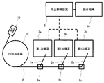
- FIG. 1 is a configuration showing the overall configuration of the particle beam irradiation system of the present embodiment.
- the particle beam therapy system 100 of the present embodiment as shown in FIG. 1 is a device for irradiating the affected portion 13a of the patient 13 with the charged particle beam 12, the charged particle beam generator 1 and the beam transport system 2. , A beam irradiation device 3, a control system 4, and an operation terminal 40 are roughly provided.
- the charged particle beam generator 1 is a device that generates a charged particle beam 12 that irradiates the affected portion 13a of the patient 13, and has an ion source 15a, a pre-stage accelerator 15b, and a circular accelerator 16.
- the ion source 15a is connected to the upstream side of the pre-stage accelerator 15b
- the circular accelerator 16 is connected to the downstream side of the pre-stage accelerator 15b.
- synchrotron is described as an example of the circular accelerator 16 in FIG. 1, various known accelerators such as a cyclotron accelerator and a synchrotron accelerator can be used in addition to the synchrotron accelerator. In that case, the pre-stage accelerator 15b may be unnecessary.
- the type of the charged particle beam 12 generated by the ion source 15a is not particularly limited, and examples of the charged particle beam 12 that irradiates the affected portion 13a of the patient 13 include protons and heavy particles such as carbon and helium.
- the beam transport system 2 is connected to the downstream side of the charged particle beam generator 1, and connects the charged particle beam generator 1 and the beam irradiation device 3.
- the beam transport system 2 transports the charged particle beam 12 from the charged particle beam generator 1 to the beam irradiation device 3.
- the beam irradiation device 3 is a device for irradiating the affected portion 13a of the patient with the charged particle beam 12 generated by the charged particle beam generator 1 and transported by the beam transport system 2, and as shown in FIG.
- a treatment table 10 on which the patient 13 is placed, an irradiation nozzle 11, and a rotating gantry 14 are roughly provided.
- a plurality of the beam irradiating devices 3 can be provided.
- the charged particle beam 12 is guided to the beam irradiating device 3 that irradiates the beam by controlling the corresponding deflecting electromagnets 9 among the plurality of deflecting electromagnets 9.
- An upstream beam monitor, a scanning electromagnet, a dose monitor, and a downstream beam monitor are arranged along the beam path in the irradiation nozzle 11, and form an irradiation field of the beam.
- the upstream beam monitor measures the passing position and beam width (beam diameter) of the charged particle beam 12 incident on the irradiation nozzle 11.
- the scanning electromagnets include a first scanning electromagnet that deflects and scans the passing charged particle beam 12 in the first direction (for example, the X-axis direction) and a second direction (for example, the Y-axis direction) perpendicular to the first direction. ), It is composed of a second scanning electromagnet that deflects and scans the charged particle beam 12.
- the X-axis direction is one direction in a plane perpendicular to the traveling direction of the charged particle beam 12 incident on the irradiation nozzle 11
- the Y-axis direction is in the plane and perpendicular to the X-axis. Indicates the direction.
- the dose monitor measures the irradiation dose of the passing charged particle beam 12. That is, the dose monitor is a monitor that monitors the irradiation dose of the charged particle beam 12 irradiated to the patient.
- the downstream beam monitor is installed on the downstream side of the scanning electromagnet and measures the position and beam width of the passing charged particle beam 12. That is, the downstream beam monitor is a monitor that measures the position and beam width of the charged particle beam 12 scanned by the scanning electromagnet.
- the irradiation method of the charged particle beam 12 in the present invention is not particularly limited, and for example, a discrete spot irradiation method in which the affected portion 13a is divided into a plurality of minute regions called spots and the charged particle beam 12 is stopped between the spots.
- the dose is adjusted to the shape of the affected area 13a using a collimator or bolus.
- An irradiation method that forms a distribution can be adopted.
- the rotating gantry 14 has a configuration that can rotate around an isocenter (not shown), and determines the irradiation angle of the beam. By rotating the rotating gantry 14, the irradiation angle of the charged particle beam 12 that irradiates the patient 13 can be changed.
- the beam irradiation device 3 can also be a fixed irradiation device that does not have a rotating gantry 14.
- the treatment table 10 is arranged in the treatment room and is a bed on which the patient 13 is placed.
- the treatment table 10 can move in the directions of three orthogonal axes based on the instruction from the control system 4, and can further move in the so-called six-axis direction, which rotates around each axis. By these movements and rotations, the position of the affected portion 13a of the patient 13 can be moved to a desired position.
- the treatment planning device 6 uses a CT image created by a CT image creating device (not shown) to determine the position of the irradiation spot for irradiating the affected area with a uniform dose and the target irradiation amount for each irradiation spot. calculate.
- the control system 4 is connected to a charged particle beam generator 1, a beam transport system 2, a beam irradiation device 3, a treatment planning device 6, an operation terminal 40, and the like, and is connected to the charged particle beam generator 1, the beam transport system 2, and It controls the operation of each device constituting the beam irradiation device 3.
- control system 4 roughly includes a central control device 5, an accelerator / transport system control system 7, and an irradiation control system 8.
- the central control device 5 is connected to the treatment planning device 6, the accelerator / transport system control system 7, the irradiation control system 8, and the operation terminal 40. Based on the setting data from the treatment planning device 6, the central control device 5 sets the setting values of the operating parameters for accelerator operation, the operating parameters for forming the irradiation field, the planned beam position and beam width, and the dose. It has a function to calculate the set value of. These operation parameters and monitor set values are output from the central control device 5 to the accelerator / transport system control system 7, the irradiation control system 8, and the operation terminal 40.
- the display screen 40a of the operation terminal 40 is masked with images or information related to a specific device by turning on / off the mask signal, which is a parameter of the central control device 5.
- the control for switching between the non-release mode displayed on the display screen 40a and the release mode displayed on the display screen 40a without masking the image or information related to the specific device is executed.
- the function in the present embodiment includes operation by pressing a button, control parameter display, status display lamp of a device or condition, command operation and display function such as input by a keyboard, and input operation.
- Images and information that are displayed / hidden by such masks are for the third beam transport system 2c, the third treatment room beam irradiation device 3c, and the third beam transport system that are additionally installed in the particle beam therapy system 100.
- the central control device 5 releases a plurality of images or information related to a specific device that was hidden by the mask at a time, preferably all image additions or information. It is desirable to do.
- the mask signal is turned off and the function is released, it is desirable that the control parameters of a specific device additionally installed, which is recorded in the central control device 5 of the control system 4, are also released.
- the input instruction for switching ON / OFF of the mask signal is input from other than the operation terminal 40.
- the command operation of the central control device 5 can also be executed by remote control by an external terminal.
- the above-mentioned mask signal is a parameter possessed by the central control device 5, and is periodically transmitted to the operation terminal 40. However, it may be transmitted to other than the operation terminal 40.
- FIG. 2 is a diagram showing the exchange of mask signals between the central control device and the operation terminal.
- the central control device 5 switches between the release mode and the non-release mode after receiving a response from the operation terminal 40 when changing the ON / OFF of the mask signal.
- the accelerator / transport system control system 7 is connected to the charged particle beam generator 1 and the beam transport system 2, and controls the operation of the devices constituting the charged particle beam generator 1 and the beam transport system 2.
- the irradiation control system 8 is connected to the beam irradiation device 3 and controls the operation of each device constituting the beam irradiation device 3.
- the operation terminal 40 is a computer that displays the state of the particle beam therapy system 100, and includes an input device and a display screen 40a for the operator (medical worker such as a doctor or operator) to input data or instruction signals.
- the operating status, treatment information, and control parameters of the devices constituting the particle beam therapy system are displayed corresponding to the data transmitted from the central control device 5.
- other functions can be displayed.
- control system 4 accelerator / transport system control system 7, irradiation control system 8, treatment planning device 6, and operation terminal 40 have a central processing unit (CPU) and a memory connected to the CPU.
- CPU central processing unit
- the control system 4 reads various motion control programs related to irradiation of each device constituting the particle beam therapy system 100 from the treatment plan created by the treatment planning device 6, executes the read programs, and accelerates / transports the particles. By outputting a command via the system control system 7 and the irradiation control system 8, the operation of each device in the particle beam therapy system 100 is controlled.
- control processing of the operation to be executed may be integrated into one program, each may be divided into a plurality of programs, or a combination thereof may be used.
- part or all of the program may be realized by dedicated hardware or may be modularized. Further, various programs may be installed in each device by a program distribution server or an external storage medium.
- each device may be an independent device connected by a wired or wireless network, or two or more may be integrated.
- FIG. 3 is a diagram that simply shows the configuration of the state before the additional treatment room is added
- FIG. 4 is a diagram that simply shows the configuration of the state after the additional treatment room is added.
- the particle beam therapy system includes one circular accelerator 16, a beam transport system 2, a first treatment room beam irradiation device 3a, a second treatment room beam irradiation device 3b, and further, as shown in FIG. 3 at the time of new construction.
- one third beam transport system 2c for transporting the beam to the third treatment room beam irradiation device 3c and the third treatment room beam irradiation device 3c is planned to be added in FIG. It has become.
- FIG. 5 is a flowchart for explaining an example of the procedure for adding the treatment room.
- the specific device to be switched between displayed and not displayed by the mask is for the third beam transport system 2c, the third treatment room beam irradiation device 3c, and the third beam transport system 2c.
- the deflection electromagnet 9c is used.
- a screen displayed on the operation terminal 40 to be used at the time of new construction is created (step S101).
- the screen is created using a debugging terminal or an operation terminal 40 delivered to the customer before construction.
- a debugging terminal it is desirable to store screen data in the operation terminal 40 before construction.
- the first treatment room beam irradiation device 3a scheduled to be constructed at the time of new construction, the first beam transport system 2a related thereto, the second treatment room beam irradiation device 3b, and the second related second treatment room beam irradiation device 3a.
- the functions of the third treatment room beam irradiation device 3c other than the beam transport system 2b and the third beam transport system 2c related thereto are also included.
- the third treatment room beam irradiation device 3c and the like will be described as an example.
- step S102 After creating the screen, set the range to be displayed or hidden by mask processing (step S102).
- a charged particle beam generator 1, a beam transport system 2, a first treatment room beam irradiation device 3a, a second treatment room beam irradiation device 3b, a control system 4, and an operation terminal 40 are newly constructed in a hospital or the like (step). S103).
- the mask signal is turned on when the system designer or the like operates the central control device 5 as a command (step S104).
- the central control device 5 masks the functions related to the third treatment room beam irradiation device 3c and the like (step S104).
- the screen displayed on the operation terminal 40 changes to the screen shown in FIG. 7 or the screen shown in FIG. 9 in detail.
- step S105 a functional test of the first treatment room beam irradiation device 3a, the second treatment room beam irradiation device 3b, and the like is executed (step S105).
- step S105 not only the function of the first treatment room beam irradiation device 3a and the second treatment room beam irradiation device 3b is tested, but also the function of the third treatment room beam irradiation device 3c and the like cannot be used. Is desirable.
- treatment is started (step S106).
- Step S107 the expansion of the third treatment room composed of the third treatment room beam irradiation device 3c, the third beam transport system 2c, the deflection electromagnet 9c, etc. is started ( Step S107).
- the period from the start of treatment to the expansion is not particularly specified, and is often determined according to the operating status of the particle beam therapy system 100 and the like.
- the central control device 5 After the installation of the structure such as the third treatment room beam irradiation device 3c is completed, the central control device 5 first determines whether or not the update work of the third treatment room beam irradiation device 3c or the like is completed (step). S108). When it is determined that the treatment is completed, the process proceeds to step S112, and the treatment using the three treatment rooms including the third treatment room beam irradiation device 3c is started (step S112).
- step S109 when it is determined that the update work of the third treatment room beam irradiation device 3c or the like has not been completed, the process proceeds to step S109.
- step S109 the central control device 5 determines whether or not the current treatment period is in effect.
- the process is returned to step S108 because the adjustment of the third treatment room beam irradiation device 3c and the like cannot be performed.
- the process proceeds to step S110 in order to adjust the third treatment room beam irradiation device 3c and the like.
- the mask signal is turned off when the system designer or the like operates the central control device 5 as a command (step S110).
- the central control device 5 unmasks the functions related to the third treatment room beam irradiation device 3c and the like, and enables the functions of the third treatment room beam irradiation device 3c and the like to be used (step S110).
- step S111 a confirmation test of the function of the extension part related to the third treatment room is performed (step S111). After the function confirmation test, the process returns to step S108 and proceeds to the treatment start step as appropriate.
- FIGS. 6 to 9 are diagrams showing an example of an operation screen after the function is released
- FIGS. 7 and 9 are diagrams showing an example of the operation screen before the function is released.
- 6 and 7 are a method using the mask symbol 41, which is an example of use on a screen for displaying the state of the device of the entire particle beam therapy system.
- the mask symbol 41 is hidden when the mask signal is turned off, and the mask symbol 41 portion can be viewed and operated.
- FIG. 7 it is displayed when the mask signal is ON, the display of the mask symbol 41 portion is invisible, a blank is displayed, and the function cannot be operated.
- the dotted line represents the mask symbol 41 and is not displayed on the actual screen.
- This method can also be used on a device status display screen, a treatment progress confirmation screen of each treatment room, a call screen of each treatment room screen, and the like.
- the mask signal is OFF, the information of the third treatment room is also output to the list in addition to the first treatment room and the second treatment room.
- the mask signal is ON, as shown in FIG. 9, masking is performed by inserting a process in which the information of the third treatment room is not output to the list. This method is also used on the control parameter list screen, registered device list screen, and the like.
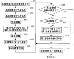
- FIGS. 10 and 11 are flowcharts for explaining another example of the procedure for adding a treatment room of the particle beam therapy system.
- the first treatment room and the second treatment room are constructed at the time of new construction, and then the third treatment room is planned to be added, and then the fourth treatment room is planned to be added.
- step S201 the display screen 40a of the operation terminal 40 including the third treatment room and the fourth treatment room to be finally constructed is created (step S201).
- the central control device 5 performs mask processing for functions related to the fourth treatment room (step S202).
- the mask signal corresponding to the mask processing in this step S202 is referred to as the fourth mask signal.
- the central control device 5 performs mask processing for the functions related to the third treatment room (step S203).
- the mask signal corresponding to the mask processing in step S203 is set as the third mask signal, and a signal different from the fourth mask signal used in step S202 is used. Thereby, it is desirable to distinguish a plurality of mask signals and surely suppress ON / OFF switching of an unintended extension device function.
- the mask treatment was explained in the order of the 4th treatment room and the 3rd treatment room, but the order may be reversed and is not particularly limited.
- a charged particle beam generator 1, a beam transport system 2, a first treatment room beam irradiation device 3a, a second treatment room beam irradiation device 3b, a control system 4, and an operation terminal 40 are newly constructed in a hospital or the like (step). S204).
- both the third mask signal and the fourth mask signal are turned on by the system designer or the like commanding the central control device 5 (step S205).
- the central control device 5 masks the functions related to the third treatment room beam irradiation device 3c, the fourth treatment room, and the like (step S205).
- step S206 a functional test of the first treatment room beam irradiation device 3a, the second treatment room beam irradiation device 3b, and the like is executed (step S206).
- step S206 as in step S105 shown in FIG. 5, not only the functional test of the first treatment room beam irradiation device 3a and the second treatment room beam irradiation device 3b, but also the third treatment room beam irradiation device 3c Etc. and confirm that the function of the 4th treatment room cannot be used.
- next steps S207 to S213 are the same as the steps S106 to S112 of FIG. 5 described above, and the details thereof will be omitted.
- the process proceeds to step S214 of FIG.
- step S214 When the system user decides to further expand the system at an arbitrary timing after the start of the treatment using the 1-3 treatment rooms, the expansion of the 4th treatment room or the like is started (step S214).
- the central control device 5 first determines whether or not the renewal work of the fourth treatment room is completed (step S215). When it is determined that the treatment is completed, the process proceeds to step S219, and the treatment using the four treatment rooms is started (step S219).
- step S216 when it is determined that the renewal work of the fourth treatment room has not been completed, the process proceeds to step S216.
- the central control device 5 determines whether or not the current treatment period is in effect (step S216). When it is determined that the treatment period is reached, the treatment is returned to step S215 because the fourth treatment room cannot be adjusted. On the other hand, when it is not determined that the treatment period is reached, the process proceeds to step S217 in order to adjust the fourth treatment room.
- the system designer or the like operates the central control device 5 as a command to turn off the fourth mask signal (step S217).
- the central control device 5 unmasks the functions related to the fourth treatment room and enables the functions of the fourth treatment room to be used (step S217).
- step S228 a confirmation test of the function of the extension part related to the fourth treatment room is performed. After the function confirmation test, the process returns to step S215 and proceeds to the treatment start step as appropriate.
- the central control device 5 of the control system 4 determines the third beam transport system 2c, the third treatment room beam irradiation device 3c, and the third beam by turning the mask signal ON / OFF.
- a non-release mode that displays on the display screen 40a of the operation terminal 40 in a state where the image or information related to the deflection electromagnet 9c for the transport system 2c is masked, the third beam transport system 2c, the third treatment room beam irradiation device 3c,
- the release mode for displaying the image or information related to the deflection electromagnet 9c for the third beam transport system 2c on the display screen 40a without masking is switched, and the display screen 40a of the operation terminal 40 is displayed in the non-release mode.
- the operation screen is updated during non-treatment hours such as nighttime and holidays while maintaining the treatment with the existing system, so that a new system can be added, adjusted, tested, etc. In doing so, it is possible to reduce the impact of treatment suspension in the existing system and carry out renewal work such as adding treatment rooms with minimal impact on the existing system.
- the central control device 5 of the control system 4 has a plurality of third beam transport systems 2c, a third treatment room beam irradiation device 3c, and a third beam irradiation device 3c, which were hidden by the mask when the mask signal was turned off. Since the image or information related to the deflection electromagnet 9c for the beam transport system 2c is released at once, it is not necessary to release the image or information in a plurality of times, and switching can be easily performed. In addition, it is possible to prevent some of the additional devices from being released differently from other devices.
- the central control device 5 of the control system 4 transmits a change signal from the central control device 5 of the control system 4 to the operation terminal 40 and receives a return from the operation terminal 40.
- the switching is performed after confirming that all the devices in the particle beam therapy system 100 have the same parameters, and the switching is performed in the system. Reliability can be ensured.
- the central control device 5 of the control system 4 is related to the deflection electromagnet 9c for the third beam transport system 2c, the third treatment room beam irradiation device 3c, and the third beam transport system 2c, which were restricted in the release mode.
- a blank is displayed as a mask on the display screen 40a as a mask symbol 41 in the portion where the image or information is displayed, so that the screen before expansion is expanded among the screens after expansion. Since it is possible to use a part with blank processing, it is not necessary to separately create different operation screens before and after the expansion, and the system update switching can be performed more smoothly.
- the input instruction for switching ON / OFF of the mask signal is input from other than the operation terminal 40 so that the mask signal is unnecessarily switched when the user mistakenly operates the particle beam therapy system 100 during treatment. Since it can be prevented, the particle beam therapy system 100 can be operated more stably.
- the control parameters of the electromagnet 9c it is possible to suppress the introduction of new control parameters to the central control device 5 at the time of expansion and the use of the electromagnet 9c when it is not needed before the expansion. Stable system operation is possible.
- the mask signals can be switched to the non-target devices by setting the mask signals individually. It can be reliably suppressed and the update work can be executed more stably.
Landscapes
- Health & Medical Sciences (AREA)
- Engineering & Computer Science (AREA)
- Biomedical Technology (AREA)
- Pathology (AREA)
- Nuclear Medicine, Radiotherapy & Molecular Imaging (AREA)
- Radiology & Medical Imaging (AREA)
- Life Sciences & Earth Sciences (AREA)
- Animal Behavior & Ethology (AREA)
- General Health & Medical Sciences (AREA)
- Public Health (AREA)
- Veterinary Medicine (AREA)
- Radiation-Therapy Devices (AREA)
Applications Claiming Priority (2)
| Application Number | Priority Date | Filing Date | Title |
|---|---|---|---|
| JP2019-099451 | 2019-05-28 | ||
| JP2019099451A JP7146695B2 (ja) | 2019-05-28 | 2019-05-28 | 粒子線治療システムおよび粒子線治療システムの操作画面更新方法 |
Publications (1)
| Publication Number | Publication Date |
|---|---|
| WO2020241311A1 true WO2020241311A1 (ja) | 2020-12-03 |
Family
ID=73548362
Family Applications (1)
| Application Number | Title | Priority Date | Filing Date |
|---|---|---|---|
| PCT/JP2020/019482 Ceased WO2020241311A1 (ja) | 2019-05-28 | 2020-05-15 | 粒子線治療システムおよび粒子線治療システムの操作画面更新方法 |
Country Status (2)
| Country | Link |
|---|---|
| JP (1) | JP7146695B2 (https=) |
| WO (1) | WO2020241311A1 (https=) |
Citations (3)
| Publication number | Priority date | Publication date | Assignee | Title |
|---|---|---|---|---|
| JP2009160309A (ja) * | 2008-01-09 | 2009-07-23 | Toshiba Corp | 放射線治療システム、放射線治療支援装置及び放射線治療支援プログラム |
| WO2014119050A1 (ja) * | 2013-01-29 | 2014-08-07 | 株式会社日立製作所 | 粒子線治療システム |
| WO2019008793A1 (ja) * | 2017-07-03 | 2019-01-10 | 三菱電機株式会社 | 粒子線照射装置 |
-
2019
- 2019-05-28 JP JP2019099451A patent/JP7146695B2/ja active Active
-
2020
- 2020-05-15 WO PCT/JP2020/019482 patent/WO2020241311A1/ja not_active Ceased
Patent Citations (3)
| Publication number | Priority date | Publication date | Assignee | Title |
|---|---|---|---|---|
| JP2009160309A (ja) * | 2008-01-09 | 2009-07-23 | Toshiba Corp | 放射線治療システム、放射線治療支援装置及び放射線治療支援プログラム |
| WO2014119050A1 (ja) * | 2013-01-29 | 2014-08-07 | 株式会社日立製作所 | 粒子線治療システム |
| WO2019008793A1 (ja) * | 2017-07-03 | 2019-01-10 | 三菱電機株式会社 | 粒子線照射装置 |
Also Published As
| Publication number | Publication date |
|---|---|
| JP7146695B2 (ja) | 2022-10-04 |
| JP2020192085A (ja) | 2020-12-03 |
Similar Documents
| Publication | Publication Date | Title |
|---|---|---|
| JP5496414B2 (ja) | 粒子線治療装置 | |
| EP3375486B1 (en) | Particle therapy system | |
| US11938342B2 (en) | Time optimized radiation treatment | |
| JP4679567B2 (ja) | 粒子線照射装置 | |
| JP4435829B2 (ja) | 粒子線照射装置 | |
| CN108025183B (zh) | 粒子治疗设备及放射治疗系统 | |
| US7834334B2 (en) | Particle therapy system | |
| JP2006128087A (ja) | 荷電粒子ビーム出射装置及び荷電粒子ビーム出射方法 | |
| JP6719344B2 (ja) | 粒子線治療システム及びシステム導入手法 | |
| JP2002113118A (ja) | 荷電粒子ビーム照射装置 | |
| US10293183B2 (en) | Particle beam treatment system | |
| WO2020137234A1 (ja) | 粒子線治療システムおよび線量分布評価システム、ならびに粒子線治療システムの作動方法 | |
| JP7146695B2 (ja) | 粒子線治療システムおよび粒子線治療システムの操作画面更新方法 | |
| US10039937B2 (en) | Charged-particle beam therapy apparatus and method for controlling charged-particle beam therapy apparatus | |
| JP6653595B2 (ja) | 粒子線治療システム | |
| Coutrakon et al. | Design considerations for medical proton accelerators | |
| US9750956B2 (en) | Determining an irradiation plan for a particle irradiation unit | |
| JP2019126462A (ja) | 荷電粒子線治療装置 | |
| EP4434577A1 (en) | Particle beam irradiation system and particle beam irradiation method | |
| JP2023142817A (ja) | 粒子線治療装置 | |
| WO2025100455A1 (ja) | 治療計画システム | |
| JP6509980B2 (ja) | 荷電粒子線治療装置、及び荷電粒子線治療装置の制御方法 | |
| WO2023243144A1 (ja) | 放射線治療システムおよびその制御方法 | |
| WO2020012688A1 (ja) | 放射線治療システムおよび治療計画データの検証方法 | |
| Li et al. | Conceptual Design of Treatment Control System for a Proton Therapy Facility at HUST |
Legal Events
| Date | Code | Title | Description |
|---|---|---|---|
| 121 | Ep: the epo has been informed by wipo that ep was designated in this application |
Ref document number: 20815656 Country of ref document: EP Kind code of ref document: A1 |
|
| NENP | Non-entry into the national phase |
Ref country code: DE |
|
| 122 | Ep: pct application non-entry in european phase |
Ref document number: 20815656 Country of ref document: EP Kind code of ref document: A1 |