WO2020240973A1 - Printer - Google Patents
Printer Download PDFInfo
- Publication number
- WO2020240973A1 WO2020240973A1 PCT/JP2020/009841 JP2020009841W WO2020240973A1 WO 2020240973 A1 WO2020240973 A1 WO 2020240973A1 JP 2020009841 W JP2020009841 W JP 2020009841W WO 2020240973 A1 WO2020240973 A1 WO 2020240973A1
- Authority
- WO
- WIPO (PCT)
- Prior art keywords
- paper
- roll paper
- sensor
- printer
- roll
- Prior art date
Links
Images


Classifications
-
- B—PERFORMING OPERATIONS; TRANSPORTING
- B41—PRINTING; LINING MACHINES; TYPEWRITERS; STAMPS
- B41J—TYPEWRITERS; SELECTIVE PRINTING MECHANISMS, i.e. MECHANISMS PRINTING OTHERWISE THAN FROM A FORME; CORRECTION OF TYPOGRAPHICAL ERRORS
- B41J15/00—Devices or arrangements of selective printing mechanisms, e.g. ink-jet printers or thermal printers, specially adapted for supporting or handling copy material in continuous form, e.g. webs
- B41J15/04—Supporting, feeding, or guiding devices; Mountings for web rolls or spindles
-
- B—PERFORMING OPERATIONS; TRANSPORTING
- B65—CONVEYING; PACKING; STORING; HANDLING THIN OR FILAMENTARY MATERIAL
- B65H—HANDLING THIN OR FILAMENTARY MATERIAL, e.g. SHEETS, WEBS, CABLES
- B65H16/00—Unwinding, paying-out webs
- B65H16/02—Supporting web roll
-
- B—PERFORMING OPERATIONS; TRANSPORTING
- B65—CONVEYING; PACKING; STORING; HANDLING THIN OR FILAMENTARY MATERIAL
- B65H—HANDLING THIN OR FILAMENTARY MATERIAL, e.g. SHEETS, WEBS, CABLES
- B65H23/00—Registering, tensioning, smoothing or guiding webs
- B65H23/02—Registering, tensioning, smoothing or guiding webs transversely
- B65H23/032—Controlling transverse register of web
-
- B—PERFORMING OPERATIONS; TRANSPORTING
- B65—CONVEYING; PACKING; STORING; HANDLING THIN OR FILAMENTARY MATERIAL
- B65H—HANDLING THIN OR FILAMENTARY MATERIAL, e.g. SHEETS, WEBS, CABLES
- B65H26/00—Warning or safety devices, e.g. automatic fault detectors, stop-motions, for web-advancing mechanisms
- B65H26/08—Warning or safety devices, e.g. automatic fault detectors, stop-motions, for web-advancing mechanisms responsive to a predetermined diameter
-
- B—PERFORMING OPERATIONS; TRANSPORTING
- B65—CONVEYING; PACKING; STORING; HANDLING THIN OR FILAMENTARY MATERIAL
- B65H—HANDLING THIN OR FILAMENTARY MATERIAL, e.g. SHEETS, WEBS, CABLES
- B65H43/00—Use of control, checking, or safety devices, e.g. automatic devices comprising an element for sensing a variable
- B65H43/02—Use of control, checking, or safety devices, e.g. automatic devices comprising an element for sensing a variable detecting, or responding to, absence of articles
Definitions
- the present invention relates to a printer.
- Patent Document 1 Japanese Patent Application Laid-Open No. 2006-232474 (hereinafter, also referred to as Patent Document 1) describes a printer provided with a pressing means for pressing a side portion of a roll paper toward a reference surface.
- Patent Document 2 Japanese Patent Application Laid-Open No. 55-16875 (hereinafter, also referred to as Patent Document 2), the lateral pressure point of the leaf spring that laterally presses the roll paper in the axial direction is arranged on the pulling side of the roll paper from the center of the roll paper.
- Patent Document 3 describes a printer provided with a pair of guide plates for pressing the front half of the side surface of the roll paper.
- the printers described in Patent Documents 1 to 3 can prevent skewing of the roll paper by pushing the side surface of the roll paper with various pressing members.
- a near-end sensor (hereinafter, also simply referred to as a sensor) that detects that the remaining amount of paper has decreased are known.
- Patent Document 4 Japanese Patent Application Laid-Open No. 2017-109335 (hereinafter, also referred to as Patent Document 4) describes a sensor that detects that the roll portion of the printing medium has moved to a predetermined area of the storage portion, and an angle with respect to the side surface of the roll portion.
- a printer is described that has a holding portion having a pair of side walls that press the side surfaces of the roll portion from both sides.
- the printer described in Patent Document 4 has the same configuration in which the roll paper is placed at a position where the sensor is arranged even when the direction of gravity applied to the roll paper stored in the print medium storage portion changes by approximately 90 °. Can be moved.
- An object of the present invention is to provide a printer capable of preventing the occurrence of skewing of roll paper regardless of the remaining amount of paper and improving the detection accuracy of a sensor that detects the remaining amount of paper.
- the printer according to the present invention has a storage unit for storing roll paper in which printing paper is rolled into a roll, a printing unit for printing on the paper, and a roll paper stored in the storage unit for transporting the paper to the printing unit.
- a transport section a push member having a push surface facing the end face of the roll paper stored in the storage section, a sensor for detecting that the remaining amount of paper wound around the roll paper has decreased to a predetermined amount, and a sensor.
- the storage unit stores the roll paper so that the center position of the roll paper moves as the amount of paper decreases, and the push-in surface until the sensor detects that the remaining amount of paper has decreased to a predetermined amount.
- the pressing surface is curved.
- the pressing member further has an inclined surface extending obliquely from the end of the pressing surface in the direction opposite to the end surface of the roll paper.
- the printer according to the present invention is an urging member that urges the surface of the pressing member facing the end surface of the roll paper from the surface opposite to the surface of the pressing member facing the end surface of the roll paper. It is preferable to have more.
- the printer according to the present invention further has a partition plate on which a pressing member and a sensor are mounted and arranged so as to be movable according to the width of the roll paper.
- the pressing member has a central portion, a first arm portion extending upward from the central portion, and a second arm portion extending downward from the central portion.
- the printer according to the present invention can prevent the occurrence of skewing of the roll paper regardless of the remaining amount of paper, and can improve the detection accuracy of the sensor that detects the remaining amount of paper.
- FIG. 1 It is a perspective view (the 1) of the printer which concerns on 1st Embodiment. It is a perspective view (the 2) of the printer which concerns on 1st Embodiment. It is a top view of the printer shown in FIG. (A) is a partially enlarged perspective view (No. 1) of the printer shown in FIG. 1, and (b) is a partially enlarged perspective view (No. 2) of the printer shown in FIG. (A) is a plan view of the partition plate shown in FIG. 1, and (b) is a rear view of the partition plate shown in FIG. 1 showing a state in which the rear case of the partition plate 24 is removed. It is an exploded perspective view of the partition plate shown in FIG.
- FIG. 1 is a diagram (No. 1) for explaining the movement of roll paper due to a decrease in the remaining amount of paper in the printer shown in FIG. 1, and (a) is a diagram in which the remaining amount of paper is reduced to a predetermined amount detected by a near-end sensor.
- FIG. 3B is a cross-sectional view of a main part of the printer along the line BB shown in FIG. 3, and FIG. 3B is shown in FIG. 3 after the remaining amount of paper has decreased to a predetermined amount detected by the near-end sensor.
- -It is sectional drawing of the main part of the printer along line B.
- FIG. 2 is a diagram (No.
- FIG. 2 2) for explaining the movement of the roll paper due to the decrease in the remaining amount of paper in the printer shown in FIG. 1, and (a) shows that the remaining amount of paper has decreased to a predetermined amount detected by the near-end sensor.
- FIG. 3B is taken along line BB shown in FIG. 3 after the remaining amount of paper has decreased to a predetermined amount detected by the near-end sensor.
- FIG. 5 is a cross-sectional view of a main part of the printer along the line DD shown in FIG. 11 for explaining the movement of the roll paper with the decrease in the remaining amount of paper in the printer shown in FIG.
- FIG. 1 is a perspective view when the upper case of the printer is opened when the roll paper is not stored in the printer
- FIG. 2 is a perspective view when the upper case of the printer is opened when the roll paper is stored in the printer. It is a figure.
- the printer 1 includes a storage unit 10, a thermal head 11, a platen roller 12, a fixed blade 13, a movable blade 14, an upper case 15, a lower case 16, a rotating shaft 17, an open / close button 18, and paper. It has a discharge port 19.
- the printer 1 is a thermal printer of a drop-in method or the like that prints characters or figures by bringing a heated thermal head 11 into contact with a roll paper 100 that is a thermal paper that changes color by heating. In the roll paper 100, the printing paper 103 is wound around a cylindrical core material in a roll shape.
- the storage portion 10 has a roll paper holder 20, a first roll paper roller 21, a second roll paper roller 22, a reference surface 23, a partition plate 24, a first guide shaft 25, and a second guide shaft. 26 and 26 are arranged, and the roll paper 100 in which the printing paper 103 is wound in a roll shape is stored.
- Each of the roll paper holder 20, the first roll paper roller 21, the second roll paper roller 22, the reference surface 23, the partition plate 24, the first guide shaft 25, and the second guide shaft 26 is arranged inside the lower case 16. To.
- the roll paper holder 20 is tilted so that the center position of the roll paper 100 moves as the amount of paper 103 decreases, and the rolls stored in the storage unit 10 together with the first roll paper roller 21 and the second roll paper roller 22. Holds the paper 100.
- the first roll paper roller 21 and the second roll paper roller 22 rotate along with the transport of the roll paper 100 while supporting the roll paper 100 together with the roll paper holder 20.
- the second roll paper roller 22 is a protrusion located between the near-end sensor 45 and the thermal head 11 and in contact with the side surface of the roll paper 100.
- the reference surface 23 is arranged so as to face one end surface 102 of the roll paper 100 stored in the storage unit 10.
- the partition plate 24 is arranged so as to face the reference surface 23 and move in the direction of the reference surface 23 according to the width of the roll paper 100, and when the roll paper 100 is stored in the storage portion 10, the other side of the roll paper 100 Facing the end face 101 of.
- the first guide shaft 25 and the second guide shaft 26 are stretched in parallel with the stretching direction of the second roll paper roller 22 and movably support the partition plate 24 in the direction orthogonal to the reference surface 23.
- the thermal head 11 is a printing unit that is arranged at a position facing the platen roller 12 when the upper case 15 is closed and prints characters or figures on the paper 103 wound around the roll paper 100.
- the paper 103 is sandwiched between the thermal head 11 and the platen roller 12 for printing.
- the thermal head 11 is pressed in the direction of the platen roller 12 by the built-in spring material, and at the same time, heats the built-in heating element according to the print data indicating the characters or figures to be printed, and prints the characters or figures on the paper 103. To do.
- the platen roller 12 is a transport unit that is rotated by a drive motor (not shown) to transport the paper 103 from the roll paper 100 stored in the storage unit 10 to the thermal head 11.
- the paper 103 sandwiched between the thermal head 11 and the platen roller 12 is conveyed by the rotation of the platen roller 12.
- the paper 103 is cut by the fixed blade 13 and the movable blade 14 at the rear end of the area to be printed, and is discharged from the paper ejection port 19.
- the fixed blade 13 is fixedly arranged between the thermal head 11 and the end face of the upper case 15 on the paper discharge port 19 side, and the movable blade 14 is formed between the platen roller 12 and the end face of the lower case 16 on the paper discharge port 19 side. It is arranged so that it can be moved vertically between them.
- the paper 103 is cut by the fixed blade 13 and the movable blade 14, and is ejected from the printer 1 in the direction indicated by the arrow A in FIG.
- the upper case 15 covers the upper part of the lower case 16 and is rotatably supported by the rotating shaft 17 on the upper part of the lower case 16.
- the upper case 15 has a window portion 150 formed on the surface thereof.
- the open / close button 18 is arranged in the upper case 15, and when pressed, the upper case 15 rotates upward with respect to the lower case 16 about the rotation shaft 17, and the upper case 15 opens.
- the printer 1 is used with the upper case 15 closed.
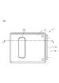
- the partition plate 24 will be described in detail with reference to FIGS. 5 and 6.
- the partition plate 24 includes a front case 41, a rear case 42, a pushing member 43, an urging member 44, a near-end sensor 45 which is also simply called a sensor, a sensor cover 46, an operating member 47, and a support plate 48. And a fastening member 49.
- the front case 41 and the rear case 42 are base materials on which the pushing member 43, the urging member 44, the near-end sensor 45, the sensor cover 46, the operating member 47, the support plate 48, and the fastening member 49 are mounted.
- the front case 41 has a facing surface 410, a first guide shaft support portion 411, a second guide shaft support portion 412, a fixing portion 413, and a first inner surface 414 opposite to the facing surface. Further, the front case 41 is formed with a first opening 415, a second opening 416, and a first shaft hole 417 penetrating from the facing surface 410 to the first inner surface 414, and the pushing member accommodating portion is formed on the facing surface 410. 418 is formed.
- the facing surface 410 faces the reference surface 23 and faces the end surface 101 of the roll paper 100 when the roll paper 100 is stored in the storage portion 10. Further, on the facing surface 410, the near-end sensor 45 is movably arranged so as to face the end surface 101 of the roll paper 100 via the first opening 415. Further, in the facing surface 410, the operating member 47 is movably arranged via the second opening 416. On the facing surface 410, a sensor position display 419 indicating the position of the near-end sensor 45 is arranged in the vicinity of the operating member 47. The sensor position display 419 displays two numbers, a number "1" indicating the first position and a number "2" indicating the second position. The first position and the second position are determined according to the diameter of the core material around which the roll paper 100 is wound. The first position and the second position may be selected by the user of the printer 1 according to the intended use and preference.
- the first guide shaft 25 penetrates the first guide shaft support portion 411, and the second guide shaft 26 penetrates the second guide shaft support portion 412.
- the fixing portion 413 is fixed to the roll paper holder 20 by engaging with the engaging portion formed on the roll paper holder 20.
- the distance between the partition plate 24 and the reference surface 23 via the first guide shaft 25 and the second guide shaft 26 can be changed according to the width of the roll paper 100, and the position coincides with the width of the roll paper 100. Is fixed by the fixing portion 413.
- the first inner surface 414 is the opposite surface of the facing surface 410, and a corrugated portion 420 having a corrugated shape is formed.
- the corrugated portion 420 corresponds to the numbers "1" and "2" displayed on the sensor position display 419 for the near-end sensor 45 moved by the operating member 47 by engaging with the arm portion 483 of the support plate 48. It is fixed in the first position and the second position.
- the rear case 42 has a second inner surface 421.
- the second inner surface 421 is formed so that a plurality of convex portions 422 are formed along the outer edge, and the second shaft hole 423 penetrates from the second inner surface 421 to the back surface at a position corresponding to the first shaft hole 417.
- the plurality of convex portions 422 engage with the concave portions formed on the outer edge of the first inner surface 414 of the front case 41 to integrate the front case 41 and the rear case 42.
- the rear case 42 has a shape corresponding to the shape of the support plate 48 around the second shaft hole 423, and a recess 424 for accommodating the support plate 48 is formed.
- the pushing member 43 includes a central portion 430, a first arm portion 431, a second arm portion 432, a shaft portion 433, a first engaging portion 434, a second engaging portion 435, and an inclined surface 436.
- the central portion 430 has a substantially circular planar shape.
- the first arm portion 431 extends linearly upward in the vertical direction so as to be separated from the central portion 430 from the outer edge of the central portion 430.
- the second arm portion 432 extends linearly from the outer edge of the central portion 430 in a direction opposite to the extending direction of the first arm portion 431, that is, downward in the vertical direction so as to be separated from the central portion 430.
- the distance between the ends of the first arm portion 431 and the second arm portion 432 and the center of the central portion 430 is substantially the same as the distance between the near-end sensor 45 and the operating member 47 and the center of the central portion 430.
- the surfaces of the central portion 430, the first arm portion 431, and the second arm portion 432 are pushing surfaces for pushing the end surface 101 of the roll paper 100.
- the shaft portion 433 stands linearly from the back surface of the central portion 430.
- the first engaging portion 434 is arranged at the tip of the first arm portion 431, and the second engaging portion 435 is arranged at the tip of the second arm portion 432.
- the first engaging portion 434 and the second engaging portion 435 fix the pushing member 43 to the front case 41 by engaging with the engaging portion formed inside the pushing member accommodating portion 418.
- the inclined surface 436 extends diagonally from the end of the pushing surface, which is the surface of the central portion 430, the first arm portion 431, and the second arm portion 432, in the direction opposite to the reference surface 23.
- the inclined surface 436 extends from both ends of the central portion 430, extends from both ends and the upper end of the first arm portion 431, and extends from both ends and the lower ends of the second arm portion 432.
- the urging member 44 is a spring that engages with the shaft portion 433 of the pushing member 43, specifically, the shaft portion 433 of the pushing member 43 penetrates the inside, and one end of the first shaft hole 417 of the front case 41. It is arranged so as to be in contact with the receiving portion formed along the inner wall and the other end to be in contact with the back surface of the central portion 430 of the pushing member 43. By pressing the urging member 44 from the back surface of the central portion 430, any portion of the central portion 430, the first arm portion 431, and the second arm portion 432 of the pushing member 43 is linearly aligned with the end surface 101 of the roll paper 100. The roll paper 100 is pushed in the direction of the reference surface in contact with each other.
- the pushing member 43 is urged from the back surface by the urging member 44.
- the pushing surface of the pushing member 43 facing the end face 101 of the roll paper 100 is projected in the vertical direction toward the end face 101 of the roll paper 100. It is curved.
- the pushing surface of the pushing member 43 is convexly curved in the vertical direction toward the end face 101 of the roll paper 100, so that the pushing surface of the pushing member 43 comes into contact with the end face 101 of the roll paper 100 by a linear portion extending in the horizontal direction.
- the near-end sensor 45 is, for example, an optical sensor, which detects that the remaining amount of the paper 103 wound around the roll paper 100 has decreased to a predetermined amount. Since the configuration and function of the near-end sensor 45 are well known, detailed description thereof will be omitted here.
- the sensor cover 46 is arranged on the back surface of the near-end sensor 45, and fixes the near-end sensor 45 to the support plate 48.
- the surface of the operating member 47 is fixed to the support plate 48 so that the surface can be seen from the facing surface 410 via the second opening 416, and when an operator (not shown) operates the position of the near-end sensor 45, the operator Manipulated by.
- the support plate 48 has a support surface 480, a sensor fixing portion 481, an operating member fixing portion 482, and an arm portion 483, and is rotatable in a plane orthogonal to the moving direction of the partition plate 24.
- the support plate 48 is formed so that the through hole 484 penetrates from the support surface 480 to the back surface of the support surface 480 at a position corresponding to each of the first shaft hole 417 and the second shaft hole 423.
- the shaft portion 433 of the pushing member 43 is inserted into the through hole 484 together with the first shaft hole 417 and the second shaft hole 423.
- the support plate 48 has a boss formed around the through hole 484 with the center of the shaft portion 433 as the center point in response to the operation member 47 fixed to the operation member fixing portion 482 being operated by the operator. Rotate as. By rotating the support plate 48, the near-end sensor 45 fixed to the sensor fixing portion 481 rotates about the shaft portion 433 around the boss formed around the through hole 484.
- the fastening member 49 is screwed with the shaft portion 433 of the pushing member 43 to fix the pushing member 43 to the front case 41.
- the fastening member 49 functions as a stopper that prevents the pushing member 43 from bending more than a certain amount and prevents the pushing member 43 from coming off from the front case 41.
- FIG. 8 shows the movement of the roll paper 100 as the remaining amount of the paper 103 decreases when the near-end sensor 45 is placed in the first position
- FIG. 9 shows the paper when the near-end sensor 45 is placed in the second position.
- the movement of the roll paper 100 with the decrease of the remaining amount of 103 is shown.
- 8 (a) and 9 (a) are cross-sectional views of a main part of the printer 1 along the line BB shown in FIG. 3 when the remaining amount of the paper 103 is reduced to a predetermined amount detected by the near-end sensor 45.
- Is. 8 (b) and 9 (b) are cross-sectional views of a main part of the printer 1 along the line BB shown in FIG. 3 after the remaining amount of the paper 103 is reduced to a predetermined amount detected by the near-end sensor 45. Is.
- the near-end sensor 45 is adjusted to two positions according to the diameter of the core material around which the roll paper is wound.
- the first position indicated by the number “1” in the sensor position display 419 is a position where the near-end sensor 45 is arranged when the diameter of the core material around which the paper 103 is wound is relatively small.
- the second position indicated by the number “2" in the sensor position display 419 is a position where the near-end sensor 45 is arranged when the diameter of the core material around which the paper 103 is wound is relatively large.
- the first position and the second position may be selected by the user of the printer 1 according to the intended use and preference.
- the roll paper 100 wound around the core material 104 is formed in the recesses indicated by arrows C in FIGS. 8 (a) and 8 (b) and 9 (a) and 9 (b) as the remaining amount of the paper 103 decreases. Move to the fitting position.
- the roll paper 100 is located between the push-in surface of the near-end sensor 45 and the push-in member 43 and the thermal head 11, and is a protrusion on which the end face 101 of the roll paper 100 comes into contact with the second roll paper roller 22 and the roll paper holder. Move while being supported by 20. As the roll paper 100 moves while being supported by the second roll paper roller 22 and the roll paper holder 20, the near-end sensor 45 and the pushing surface of the pushing member 43 are sequentially separated from the end face 101 of the roll paper 100.
- the near-end sensor 45 detects that the remaining amount of the paper 103 of the roll paper 100 has decreased to a predetermined amount.
- the pushing member 43 contacts the end face 101 of the opposing roll paper 100 until the near-end sensor 45 detects that the remaining amount of the paper 103 has decreased to a predetermined amount.
- the pushing member 43 is separated from the end face 101 of the roll paper 100 after the near-end sensor 45 detects that the remaining amount of the paper 103 has decreased to a predetermined amount. ..
- the pushing force is not applied to the roll paper 100 from the pushing member 43.
- the printer 2 is different from the printer 1 in that the partition plate 34 is arranged in the storage unit 10 instead of the partition plate 24. Since the configurations and functions of the components of the printer 2 other than the partition plate 34 are the same as the configurations and functions of the components of the printer 1 with the same reference numerals, detailed description thereof will be omitted here.
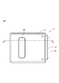
- the partition plate 34 will be described in detail with reference to FIGS. 13 and 14.
- the partition plate 34 differs from the partition plate 24 in that the front case 51 is provided in place of the front case 41.
- the front case 51 differs from the front case 41 in that the first opening 515, the second opening 516, and the corrugated portion 520 are formed in place of the first opening 415, the second opening 416, and the corrugated portion 420. ..
- the front case 51 is different from the front case 41 in that the sensor position display 519 is arranged instead of the sensor position display 419.
- the components of the partition plate 34 other than the first opening 515, the second opening 516, the sensor position display 519, and the corrugated portion 520 are the components and functions of the partition plate 24 having the same reference numerals. Since it is the same as the above, detailed description thereof will be omitted here.
- the first opening 515 and the second opening 516 are through holes penetrating from the facing surface 410 to the first inner surface 414, and the length in the longitudinal direction is longer than that of the first opening 415 and the second opening 416, respectively. long.
- the near-end sensor 45 is movably arranged in the first opening 515 so as to face the end surface 101 of the roll paper 100, and the operating member 47 is movably arranged in the second opening 416.
- the sensor position display 519 is arranged in the vicinity of the operating member 47 and indicates the position of the near-end sensor 45.
- the sensor position display 519 displays five numbers from the number "1" indicating the first position to the number "5" indicating the fifth position.
- the corrugated portion 520 is formed on the first inner surface 414, and by engaging with the arm portion 483 of the support plate 48, the near-end sensor 45 moved by the operating member 47 is displayed on the sensor position display 519 by the number “1”. It is fixed at the first to fifth positions corresponding to each of "5".
- the near-end sensor 45 is adjusted to five positions according to the diameter of the core material around which the paper 103 is wound.
- the first position indicated by the number “1" in the sensor position display 519 is the position where the near-end sensor 45 is arranged when the diameter of the core material around which the paper 103 is wound is the smallest.
- the fifth position indicated by the number "5" in the sensor position display 519 is a position where the near-end sensor 45 is arranged when the diameter of the core material around which the paper 103 is wound is the largest.
- the second position, the third position, and the fourth position indicated by the numbers "2", "3", and "4" in the sensor position display 519 the diameter of the core material around which the paper 103 is wound is thick. This is the position where the near-end sensor 45 is arranged.
- the first position, the second position, the third position, the fourth position, and the fifth position may be selected by the user of the printer 2 according to the intended use and preference.
- the roll paper 100 wound around the core material 104 is lowered in height as the remaining amount of the paper 103 decreases, and the core material 104 is moved so as to cross the pressing member 43.
- the pushing member 43 contacts the end face 101 of the opposing roll paper 100 until the near-end sensor 45 detects that the remaining amount of the paper 103 has decreased to a predetermined amount. Further, the pushing member 43 is separated from the end face 101 of the roll paper 100 after the near-end sensor 45 detects that the remaining amount of the paper 103 has decreased to a predetermined amount. When the pushing member 43 is separated from the end face 101 of the roll paper 100, the pushing force is not applied to the roll paper 100 from the pushing member 43.
- the pressing member 43 keeps the end face 101 of the roll paper 100 until the near-end sensor 45 detects that the remaining amount of the paper 103 has decreased to a predetermined amount at all the positions from the first position to the fifth position. You don't have to stay in contact with. Further, in the printer 2, before the near-end sensor 45 detects that the remaining amount of the paper 103 has decreased to a predetermined amount at all the positions from the first position to the fifth position, the pressing member 43 is the end face of the roll paper 100. It does not have to be separated from 101. Further, in the printer 2, the pressing member 43 does not have to be separated from the end face 101 of the roll paper 100.
- the pushing member 43 contacts the end face 101 of the opposing roll paper 100 until the near-end sensor 45 detects that the remaining amount of the paper 103 has decreased to a predetermined amount, so that the roll paper 100 is skewed. And the slackening of the roll paper 100 is reduced.
- the push-in surface is separated from the end face of the roll paper after the near-end sensor 45 detects that the remaining amount of paper has decreased to a predetermined amount, but when the roll paper is separated from the push-in member 43.
- the paper diameter is small enough that the roll paper does not skew after the push-in surface is separated from the end face of the roll paper.
- the distance between the end face 101 and the near-end sensor 45 is kept constant. Will be done. In the printers 1 and 2, since the distance between the end face 101 and the near-end sensor 45 is kept constant, the detection accuracy of the near-end sensor 45 is improved.
- the pressing member 43 separates from the end face 101, so that when the remaining amount of the paper 103 becomes low.
- the pushing force is not excessively applied to the roll paper 100.
- the pushing force is not excessively applied to the roll paper 100, so that there is a low possibility that a problem will occur in the transport of the paper 103.
- the pushing member 43 can push the end face 101 of the opposing roll paper 100 by line contact instead of surface contact.
- the pushing member 43 pushes the end face 101 of the roll paper 100 by line contact, the magnitude of the frictional force generated does not become larger than the surface contact, so that there is a possibility that a problem may occur in the transport of the paper 103. Is low.
- the pushing member 43 since the pushing member 43 further has an inclined surface 436 extending obliquely from the end of the pushing surface in the direction opposite to the reference surface 23, the pushing member 43 extends from the end surface 101 of the roll paper 100. Gradually separate. In the printers 1 and 2, since the pushing member 43 is gradually separated from the end face 101 of the roll paper 100, the pushing force of the pushing member 43 pushing the end face 101 of the roll paper 100 is gradually reduced. In the printers 1 and 2, since the pushing force by the pushing member 43 is gradually reduced, there is no possibility that a problem due to a sudden change in the pushing force applied to the roll paper 100 will occur.
- the printers 1 and 2 since the urging member 44 for urging the pushing surface of the pushing member 43 in the direction of the reference surface 23 is arranged between the pushing member 43 and the support plate 48, the printers 1 and 2 are stored in the storage section 10.
- the end face 101 of the rolled paper 100 can be pushed in with a force corresponding to the elastic force of the urging member 44.
- the printers 1 and 2 are arranged so that the urging member 44 is in contact with the receiving portion formed along the inner wall of the first shaft hole 417, the urging member 44 can be arranged in a smaller size. it can.
- the pressing member 43 pushes the end surface 101 of the roll paper 100 on the surfaces of the first arm portion 431 and the second arm portion 432 in addition to the central portion 430, so that the diameter of the roll paper 100 becomes large. Even if it becomes thin, the end face 101 of the roll paper 100 can be continuously pushed.
- each of the first arm portion 431 and the second arm portion 432 of the pushing member 43 extends in the vertical direction, but in the printer according to the embodiment, the arm portion of the pushing member is inclined from the vertical direction. May be placed. Further, in the printer according to the embodiment, the number of arms of the pressing member may be one or three or more.
- the distance between the end portions of the first arm portion 431 and the second arm portion 432 of the pushing member 43 and the center of the central portion 430 is set to the center of the near-end sensor 45, the operating member 47, and the central portion 430. It is almost the same as the distance between.
- the distance between the end of the arm portion of the pushing member and the center of the central portion is longer than the distance between the near-end sensor 45 and the operating member 47 and the center of the central portion 430. It may be short or short.
- the printer 1 is a thermal printer
- the printer 1 according to the embodiment is not limited to the thermal printer, and may be any one that uses roll paper.
- the printer 1 according to the embodiment may be a printer of another printing format such as an inkjet printer, an electrophotographic printer, a dot impact printer, and a sublimation printer.
Abstract
A printer that has: a housing unit that houses a paper roll of printing paper that is wound into a roll; a printing unit that prints on paper; a transport unit that transports paper from the paper roll housed in the housing unit to the printing unit; a pressing member having a pressing surface facing an end surface of the paper roll housed in the housing unit; and a sensor that detects that the remaining paper wound on the paper roll has reduced to a prescribed amount. The housing unit houses the paper roll such that the center position of the paper roll moves in accordance with the reduction in paper and the sensor and pressing surface are arranged relative to the housing unit such that the pressing surface abuts the end of the paper roll until the sensor detects that the remaining paper has reduced to the prescribed amount and such that the pressing surface separates from the end surface of the paper roll after the sensor has detected that the remaining paper has reduced to the prescribed amount.
Description
本発明は、プリンタに関する。
The present invention relates to a printer.
ドロップイン方式等のロール紙を用いたプリンタにおいて、ロール紙の斜行を防止するための種々の技術が知られている。
In a printer using roll paper such as a drop-in method, various techniques for preventing skewing of roll paper are known.
例えば、特開2006-232474号公報(以下、特許文献1とも称する)には、ロール紙の側部を基準面に向けて押圧する押圧手段を設けたプリンタが記載されている。また、特開昭55-16875号公報(以下、特許文献2とも称する)には、ロール紙を軸方向に側圧する板バネの側圧点をロール紙の中心よりもロール紙の引っ張り側に配置したプリンタが記載されている。さらに、実開平3-84151号公報(以下、特許文献3とも称する)には、ロール紙の側面の前半部を押圧する一対のガイド板を設けたプリンタが記載されている。特許文献1~3に記載されるプリンタは、ロール紙の側面を種々の押込部材によって押し込むことでロール紙の斜行を防止できる。
For example, Japanese Patent Application Laid-Open No. 2006-232474 (hereinafter, also referred to as Patent Document 1) describes a printer provided with a pressing means for pressing a side portion of a roll paper toward a reference surface. Further, in Japanese Patent Application Laid-Open No. 55-16875 (hereinafter, also referred to as Patent Document 2), the lateral pressure point of the leaf spring that laterally presses the roll paper in the axial direction is arranged on the pulling side of the roll paper from the center of the roll paper. The printer is listed. Further, Japanese Patent Application Laid-Open No. 3-84151 (hereinafter, also referred to as Patent Document 3) describes a printer provided with a pair of guide plates for pressing the front half of the side surface of the roll paper. The printers described in Patent Documents 1 to 3 can prevent skewing of the roll paper by pushing the side surface of the roll paper with various pressing members.
また、用紙の残量が減少したことを検出するニアエンドセンサ(以下、単にセンサとも称する)の検出機能を向上させる種々の技術が知られている。
Further, various techniques for improving the detection function of a near-end sensor (hereinafter, also simply referred to as a sensor) that detects that the remaining amount of paper has decreased are known.
例えば、特開2017-109335号公報(以下、特許文献4とも称する)には、印字媒体のロール部が収納部の所定領域に移動したことを検知するセンサと、ロール部の側面に対して角度を有し、ロール部の側面を両側から押圧する一対の側壁を備える保持部とを有するプリンタが記載されている。特許文献4に記載されるプリンタは、印字媒体収納部に収納されているロール紙に印加される重力の方向が概ね90°変化した場合でも、同一構成でロール紙をセンサが配置される位置に移動させることができる。
For example, Japanese Patent Application Laid-Open No. 2017-109335 (hereinafter, also referred to as Patent Document 4) describes a sensor that detects that the roll portion of the printing medium has moved to a predetermined area of the storage portion, and an angle with respect to the side surface of the roll portion. A printer is described that has a holding portion having a pair of side walls that press the side surfaces of the roll portion from both sides. The printer described in Patent Document 4 has the same configuration in which the roll paper is placed at a position where the sensor is arranged even when the direction of gravity applied to the roll paper stored in the print medium storage portion changes by approximately 90 °. Can be moved.
しかしながら、特許文献1~4のそれぞれに記載されるプリンタでは、用紙の残量にかかわらずロール紙の側面を一定の力で押し込むため、用紙の残量が少なくなったときに押込力がロール紙に過剰に印加され、ロール紙の搬送に不具合が生じるおそれがある。
However, in the printers described in Patent Documents 1 to 4, since the side surface of the roll paper is pushed with a constant force regardless of the remaining amount of paper, the pushing force is applied to the roll paper when the remaining amount of paper is low. Is applied excessively to the paper, which may cause a problem in transporting the roll paper.
本発明は、用紙の残量にかかわらずロール紙の斜行の発生を防止すると共に、用紙の残量を検出するセンサの検出精度が向上可能なプリンタを提供することを目的とする。
An object of the present invention is to provide a printer capable of preventing the occurrence of skewing of roll paper regardless of the remaining amount of paper and improving the detection accuracy of a sensor that detects the remaining amount of paper.
本発明に係るプリンタは、印字用の用紙をロール状に巻回したロール紙を収納する収納部と、用紙に印字する印字部と、収納部に収納されたロール紙から用紙を印字部へ搬送する搬送部と、収納部に収納されたロール紙の端面に対向する押込面を有する押込部材と、ロール紙に巻回された用紙の残量が所定量まで減少したことを検出するセンサと、を有し、収納部は、用紙の減少に応じてロール紙の中心位置が移動するようにロール紙を収納し、センサが用紙の残量が所定量まで減少したことを検出するまでは押込面がロール紙の端面に接触し、センサが用紙の残量が所定量まで減少したことを検出した後に押込面がロール紙の一方の端面から離隔するように、収納部に対してセンサ及び押込面が配置される。
The printer according to the present invention has a storage unit for storing roll paper in which printing paper is rolled into a roll, a printing unit for printing on the paper, and a roll paper stored in the storage unit for transporting the paper to the printing unit. A transport section, a push member having a push surface facing the end face of the roll paper stored in the storage section, a sensor for detecting that the remaining amount of paper wound around the roll paper has decreased to a predetermined amount, and a sensor. The storage unit stores the roll paper so that the center position of the roll paper moves as the amount of paper decreases, and the push-in surface until the sensor detects that the remaining amount of paper has decreased to a predetermined amount. Touches the end face of the roll paper, and after the sensor detects that the remaining amount of paper has decreased to a predetermined amount, the sensor and the push surface are separated from one end face of the roll paper so that the push-in surface is separated from one end face of the roll paper. Is placed.
さらに、本発明に係るプリンタでは、押込面は、湾曲していることが好ましい。
Further, in the printer according to the present invention, it is preferable that the pressing surface is curved.
さらに、本発明に係るプリンタでは、押込部材は、押込面の端部からロール紙の端面と反対の方向に斜めに延伸する傾斜面を更に有することが好ましい。
Further, in the printer according to the present invention, it is preferable that the pressing member further has an inclined surface extending obliquely from the end of the pressing surface in the direction opposite to the end surface of the roll paper.
さらに、本発明に係るプリンタは、押込部材のロール紙の端面に対向する面の反対の面から押込部材のロール紙の端面に対向する面をロール紙の端面の方向に付勢する付勢部材を更に有することが好ましい。
Further, the printer according to the present invention is an urging member that urges the surface of the pressing member facing the end surface of the roll paper from the surface opposite to the surface of the pressing member facing the end surface of the roll paper. It is preferable to have more.
さらに、本発明に係るプリンタは、押込部材及びセンサを搭載し、ロール紙の幅に応じて移動可能に配置される仕切り板を更に有することが好ましい。
Further, it is preferable that the printer according to the present invention further has a partition plate on which a pressing member and a sensor are mounted and arranged so as to be movable according to the width of the roll paper.
さらに、本発明に係るプリンタでは、押込部材は、中央部と、中央部から上方に延伸する第1腕部と、中央部から下方に延伸する第2腕部とを有することが好ましい。
Further, in the printer according to the present invention, it is preferable that the pressing member has a central portion, a first arm portion extending upward from the central portion, and a second arm portion extending downward from the central portion.
本発明に係るプリンタは、用紙の残量にかかわらずロール紙の斜行の発生を防止すると共に、用紙の残量を検出するセンサの検出精度を向上させることができる。
The printer according to the present invention can prevent the occurrence of skewing of the roll paper regardless of the remaining amount of paper, and can improve the detection accuracy of the sensor that detects the remaining amount of paper.
以下、図面を参照して、本発明に係るプリンタについて説明する。ただし、本発明の技術的範囲はそれらの実施の形態には限定されず、特許請求の範囲に記載された発明とその均等物に及ぶ点に留意されたい。
Hereinafter, the printer according to the present invention will be described with reference to the drawings. However, it should be noted that the technical scope of the present invention is not limited to those embodiments and extends to the inventions described in the claims and their equivalents.
(第1実施形態に係るプリンタの構成及び機能)
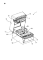
図1~4を参照して、第1実施形態に係るプリンタの構成及び機能について説明する。図1はプリンタにロール紙を収納していない状態でプリンタの上ケースが開いたときの斜視図であり、図2はプリンタにロール紙を収納した状態でプリンタの上ケースが開いたときの斜視図である。 (The configuration and function of the printer according to the first embodiment)
The configuration and function of the printer according to the first embodiment will be described with reference to FIGS. 1 to 4. FIG. 1 is a perspective view when the upper case of the printer is opened when the roll paper is not stored in the printer, and FIG. 2 is a perspective view when the upper case of the printer is opened when the roll paper is stored in the printer. It is a figure.
プリンタ1は、収納部10と、サーマルヘッド11と、プラテンローラ12と、固定刃13と、可動刃14と、上ケース15と、下ケース16と、回転軸17と、開閉ボタン18と、用紙排出口19とを有する。プリンタ1は、加熱により変色する感熱紙であるロール紙100に、加熱されたサーマルヘッド11を接触させることで文字又は図形を印字するドロップイン方式等のサーマルプリンタである。ロール紙100は、円筒状の芯材に印字用の用紙103をロール状に巻回している。
The printer 1 includes a storage unit 10, a thermal head 11, a platen roller 12, a fixed blade 13, a movable blade 14, an upper case 15, a lower case 16, a rotating shaft 17, an open / close button 18, and paper. It has a discharge port 19. The printer 1 is a thermal printer of a drop-in method or the like that prints characters or figures by bringing a heated thermal head 11 into contact with a roll paper 100 that is a thermal paper that changes color by heating. In the roll paper 100, the printing paper 103 is wound around a cylindrical core material in a roll shape.
収納部10は、ロール紙ホルダ20を有し、第1ロール紙ローラ21と、第2ロール紙ローラ22と、基準面23と、仕切り板24と、第1ガイド軸25と、第2ガイド軸26とが配置され、印字用の用紙103をロール状に巻回したロール紙100を収納する。ロール紙ホルダ20、第1ロール紙ローラ21、第2ロール紙ローラ22、基準面23、仕切り板24、第1ガイド軸25及び第2ガイド軸26のそれぞれは、下ケース16の内部に配置される。
The storage portion 10 has a roll paper holder 20, a first roll paper roller 21, a second roll paper roller 22, a reference surface 23, a partition plate 24, a first guide shaft 25, and a second guide shaft. 26 and 26 are arranged, and the roll paper 100 in which the printing paper 103 is wound in a roll shape is stored. Each of the roll paper holder 20, the first roll paper roller 21, the second roll paper roller 22, the reference surface 23, the partition plate 24, the first guide shaft 25, and the second guide shaft 26 is arranged inside the lower case 16. To.
ロール紙ホルダ20は、用紙103の減少に応じてロール紙100の中心位置が移動するように傾斜し、第1ロール紙ローラ21及び第2ロール紙ローラ22と共に、収納部10に収納されたロール紙100を保持する。第1ロール紙ローラ21及び第2ロール紙ローラ22は、ロール紙ホルダ20と共にロール紙100を支持しながら、ロール紙100の搬送に伴って回転する。第2ロール紙ローラ22は、ニアエンドセンサ45とサーマルヘッド11との間に位置し、ロール紙100の側面が接触する突起部である。
The roll paper holder 20 is tilted so that the center position of the roll paper 100 moves as the amount of paper 103 decreases, and the rolls stored in the storage unit 10 together with the first roll paper roller 21 and the second roll paper roller 22. Holds the paper 100. The first roll paper roller 21 and the second roll paper roller 22 rotate along with the transport of the roll paper 100 while supporting the roll paper 100 together with the roll paper holder 20. The second roll paper roller 22 is a protrusion located between the near-end sensor 45 and the thermal head 11 and in contact with the side surface of the roll paper 100.
基準面23は、収納部10に収納されたロール紙100の一方の端面102に対向して配置される。仕切り板24は、基準面23に対向し且つ基準面23の方向にロール紙100の幅に応じて移動可能に配置され、収納部10にロール紙100が収納されたとき、ロール紙100の他方の端面101に対向する。第1ガイド軸25及び第2ガイド軸26は、第2ロール紙ローラ22の延伸方向と平行に延伸し、基準面23の直交する方向に仕切り板24を移動可能に支持する。
The reference surface 23 is arranged so as to face one end surface 102 of the roll paper 100 stored in the storage unit 10. The partition plate 24 is arranged so as to face the reference surface 23 and move in the direction of the reference surface 23 according to the width of the roll paper 100, and when the roll paper 100 is stored in the storage portion 10, the other side of the roll paper 100 Facing the end face 101 of. The first guide shaft 25 and the second guide shaft 26 are stretched in parallel with the stretching direction of the second roll paper roller 22 and movably support the partition plate 24 in the direction orthogonal to the reference surface 23.
サーマルヘッド11は、上ケース15が閉まったときにプラテンローラ12と対向する位置に配置され、ロール紙100に巻回された用紙103に文字又は図形を印字する印字部である。用紙103は、サーマルヘッド11とプラテンローラ12とに挟持されて印字される。サーマルヘッド11は、内蔵されるバネ材によりプラテンローラ12の方向に押圧されると共に、印字する文字又は図形を示す印字データに応じて内蔵する発熱体を発熱させ、用紙103に文字又は図形を印字する。
The thermal head 11 is a printing unit that is arranged at a position facing the platen roller 12 when the upper case 15 is closed and prints characters or figures on the paper 103 wound around the roll paper 100. The paper 103 is sandwiched between the thermal head 11 and the platen roller 12 for printing. The thermal head 11 is pressed in the direction of the platen roller 12 by the built-in spring material, and at the same time, heats the built-in heating element according to the print data indicating the characters or figures to be printed, and prints the characters or figures on the paper 103. To do.
プラテンローラ12は、不図示の駆動モータにより回転して収納部10に収納されたロール紙100から用紙103をサーマルヘッド11へ搬送する搬送部である。サーマルヘッド11とプラテンローラ12とによって挟持された用紙103は、プラテンローラ12が回転することによって搬送される。サーマルヘッド11によりロール紙100に印字された後に、用紙103は被印字領域の後端で固定刃13及び可動刃14によって切断され、用紙排出口19から排出される。
The platen roller 12 is a transport unit that is rotated by a drive motor (not shown) to transport the paper 103 from the roll paper 100 stored in the storage unit 10 to the thermal head 11. The paper 103 sandwiched between the thermal head 11 and the platen roller 12 is conveyed by the rotation of the platen roller 12. After printing on the roll paper 100 by the thermal head 11, the paper 103 is cut by the fixed blade 13 and the movable blade 14 at the rear end of the area to be printed, and is discharged from the paper ejection port 19.
固定刃13はサーマルヘッド11と上ケース15の用紙排出口19側の端面との間に固定して配置され、可動刃14はプラテンローラ12と下ケース16の用紙排出口19側の端面との間に鉛直方向に移動可能に配置される。用紙103は、サーマルヘッド11により印字された後に、固定刃13及び可動刃14によって切断され、図2において矢印Aで示される方向にプリンタ1から排出される。
The fixed blade 13 is fixedly arranged between the thermal head 11 and the end face of the upper case 15 on the paper discharge port 19 side, and the movable blade 14 is formed between the platen roller 12 and the end face of the lower case 16 on the paper discharge port 19 side. It is arranged so that it can be moved vertically between them. After being printed by the thermal head 11, the paper 103 is cut by the fixed blade 13 and the movable blade 14, and is ejected from the printer 1 in the direction indicated by the arrow A in FIG.
上ケース15は、下ケース16の上部を覆い、下ケース16の上部に回転軸17によって回転自在に支持されている。上ケース15は、表面に窓部150が形成される。開閉ボタン18は、上ケース15に配置され、押下されることに応じて、回転軸17を中心として、上ケース15が下ケース16に対して上方に回転して、上ケース15が開く。なお、プリンタ1は、上ケース15が閉じた状態で使用される。
The upper case 15 covers the upper part of the lower case 16 and is rotatably supported by the rotating shaft 17 on the upper part of the lower case 16. The upper case 15 has a window portion 150 formed on the surface thereof. The open / close button 18 is arranged in the upper case 15, and when pressed, the upper case 15 rotates upward with respect to the lower case 16 about the rotation shaft 17, and the upper case 15 opens. The printer 1 is used with the upper case 15 closed.
図5及び6を参照して、仕切り板24について詳細に説明する。
The partition plate 24 will be described in detail with reference to FIGS. 5 and 6.
仕切り板24は、フロントケース41と、リアケース42と、押込部材43と、付勢部材44と、単にセンサとも称されるニアエンドセンサ45と、センサカバー46と、操作部材47と、支持板48と、締結部材49とを有する。フロントケース41及びリアケース42は、押込部材43、付勢部材44、ニアエンドセンサ45、センサカバー46、操作部材47、支持板48及び締結部材49を搭載する基材である。
The partition plate 24 includes a front case 41, a rear case 42, a pushing member 43, an urging member 44, a near-end sensor 45 which is also simply called a sensor, a sensor cover 46, an operating member 47, and a support plate 48. And a fastening member 49. The front case 41 and the rear case 42 are base materials on which the pushing member 43, the urging member 44, the near-end sensor 45, the sensor cover 46, the operating member 47, the support plate 48, and the fastening member 49 are mounted.
フロントケース41は、対向面410と、第1ガイド軸支持部411と、第2ガイド軸支持部412と、固定部413と、対向面の反対の第1内面414とを有する。また、フロントケース41は、対向面410から第1内面414に貫通する第1開口部415、第2開口部416、及び第1軸穴417が形成されると共に、対向面410に押込部材収納部418が形成される。
The front case 41 has a facing surface 410, a first guide shaft support portion 411, a second guide shaft support portion 412, a fixing portion 413, and a first inner surface 414 opposite to the facing surface. Further, the front case 41 is formed with a first opening 415, a second opening 416, and a first shaft hole 417 penetrating from the facing surface 410 to the first inner surface 414, and the pushing member accommodating portion is formed on the facing surface 410. 418 is formed.
対向面410は、基準面23に対向すると共に、収納部10にロール紙100が収納されたときに、ロール紙100の端面101に対向する。また、対向面410は、第1開口部415を介してニアエンドセンサ45がロール紙100の端面101に対向して移動可能に配置される。さらに、対向面410は、第2開口部416を介して操作部材47が移動可能に配置される。対向面410は、操作部材47の近傍にニアエンドセンサ45の位置を示すセンサ位置表示419が配置される。センサ位置表示419は、第1位置を示す数字「1」及び第2位置を示す数字「2」の2つの数字が表示される。第1位置及び第2位置は、ロール紙100が巻回される芯材の径の太さに応じて決定される。なお、第1位置及び第2位置は、プリンタ1の使用者が使用用途及び好みに応じて選択されてもよい。
The facing surface 410 faces the reference surface 23 and faces the end surface 101 of the roll paper 100 when the roll paper 100 is stored in the storage portion 10. Further, on the facing surface 410, the near-end sensor 45 is movably arranged so as to face the end surface 101 of the roll paper 100 via the first opening 415. Further, in the facing surface 410, the operating member 47 is movably arranged via the second opening 416. On the facing surface 410, a sensor position display 419 indicating the position of the near-end sensor 45 is arranged in the vicinity of the operating member 47. The sensor position display 419 displays two numbers, a number "1" indicating the first position and a number "2" indicating the second position. The first position and the second position are determined according to the diameter of the core material around which the roll paper 100 is wound. The first position and the second position may be selected by the user of the printer 1 according to the intended use and preference.
第1ガイド軸支持部411は第1ガイド軸25が貫通し、第2ガイド軸支持部412は第2ガイド軸26が貫通する。固定部413は、ロール紙ホルダ20に形成される係合部と係合することで、ロール紙ホルダ20に固定される。仕切り板24は、ロール紙100の幅に応じて第1ガイド軸25及び第2ガイド軸26を介して基準面23との間の距離が変更可能であり、ロール紙100の幅と一致する位置で固定部413によって固定される。
The first guide shaft 25 penetrates the first guide shaft support portion 411, and the second guide shaft 26 penetrates the second guide shaft support portion 412. The fixing portion 413 is fixed to the roll paper holder 20 by engaging with the engaging portion formed on the roll paper holder 20. The distance between the partition plate 24 and the reference surface 23 via the first guide shaft 25 and the second guide shaft 26 can be changed according to the width of the roll paper 100, and the position coincides with the width of the roll paper 100. Is fixed by the fixing portion 413.
第1内面414は、対向面410の反対の面であり、波形の形状を有する波形部420が形成される。波形部420は、支持板48の腕部483と係合することで、操作部材47によって移動されるニアエンドセンサ45をセンサ位置表示419に表示される数字「1」及び「2」のそれぞれに対応する第1位置及び第2位置に固定する。
The first inner surface 414 is the opposite surface of the facing surface 410, and a corrugated portion 420 having a corrugated shape is formed. The corrugated portion 420 corresponds to the numbers "1" and "2" displayed on the sensor position display 419 for the near-end sensor 45 moved by the operating member 47 by engaging with the arm portion 483 of the support plate 48. It is fixed in the first position and the second position.
リアケース42は、第2内面421を有する。第2内面421は、外縁に沿って複数の凸部422が形成されると共に、第1軸穴417に対応する位置に第2軸穴423が第2内面421から裏面に貫通するように形成される。複数の凸部422は、フロントケース41の第1内面414の外縁に形成される凹部と係合して、フロントケース41とリアケース42とを一体化させる。また、リアケース42は、第2軸穴423の周囲に支持板48の形状に対応する形状を有し、支持板48を収容する凹部424が形成される。
The rear case 42 has a second inner surface 421. The second inner surface 421 is formed so that a plurality of convex portions 422 are formed along the outer edge, and the second shaft hole 423 penetrates from the second inner surface 421 to the back surface at a position corresponding to the first shaft hole 417. To. The plurality of convex portions 422 engage with the concave portions formed on the outer edge of the first inner surface 414 of the front case 41 to integrate the front case 41 and the rear case 42. Further, the rear case 42 has a shape corresponding to the shape of the support plate 48 around the second shaft hole 423, and a recess 424 for accommodating the support plate 48 is formed.
押込部材43は、中央部430と、第1腕部431と、第2腕部432と、軸部433と、第1係合部434と、第2係合部435と、傾斜面436とを有する。中央部430は略円形の平面形状を有する。第1腕部431は、中央部430の外縁から中央部430から離隔するように直線状に鉛直方向上方に延伸する。第2腕部432は、中央部430の外縁から第1腕部431の延伸方向と反対の方向、すなわち鉛直方向下方に中央部430から離隔するように直線状に延伸する。第1腕部431及び2腕部432の端部と中央部430の中心との間の距離は、ニアエンドセンサ45及び操作部材47と中央部430の中心との間の距離と略同一である。中央部430、第1腕部431及び第2腕部432の表面は、ロール紙100の端面101を押し込む押込面である。
The pushing member 43 includes a central portion 430, a first arm portion 431, a second arm portion 432, a shaft portion 433, a first engaging portion 434, a second engaging portion 435, and an inclined surface 436. Have. The central portion 430 has a substantially circular planar shape. The first arm portion 431 extends linearly upward in the vertical direction so as to be separated from the central portion 430 from the outer edge of the central portion 430. The second arm portion 432 extends linearly from the outer edge of the central portion 430 in a direction opposite to the extending direction of the first arm portion 431, that is, downward in the vertical direction so as to be separated from the central portion 430. The distance between the ends of the first arm portion 431 and the second arm portion 432 and the center of the central portion 430 is substantially the same as the distance between the near-end sensor 45 and the operating member 47 and the center of the central portion 430. The surfaces of the central portion 430, the first arm portion 431, and the second arm portion 432 are pushing surfaces for pushing the end surface 101 of the roll paper 100.
軸部433は、中央部430の裏面から直線状に起立する。第1係合部434は第1腕部431の先端に配置され、第2係合部435は第2腕部432の先端に配置される。第1係合部434及び第2係合部435は、押込部材収納部418の内部に形成される係合部と係合することで、押込部材43をフロントケース41に固定する。
The shaft portion 433 stands linearly from the back surface of the central portion 430. The first engaging portion 434 is arranged at the tip of the first arm portion 431, and the second engaging portion 435 is arranged at the tip of the second arm portion 432. The first engaging portion 434 and the second engaging portion 435 fix the pushing member 43 to the front case 41 by engaging with the engaging portion formed inside the pushing member accommodating portion 418.
傾斜面436は、中央部430、第1腕部431及び第2腕部432の表面である押込面の端部から基準面23と反対の方向に斜めに延伸する。傾斜面436は、中央部430の両端から延伸し、第1腕部431の両端及び上端から延伸し、第2腕部432の両端及び下端から延伸する。
The inclined surface 436 extends diagonally from the end of the pushing surface, which is the surface of the central portion 430, the first arm portion 431, and the second arm portion 432, in the direction opposite to the reference surface 23. The inclined surface 436 extends from both ends of the central portion 430, extends from both ends and the upper end of the first arm portion 431, and extends from both ends and the lower ends of the second arm portion 432.
付勢部材44は、押込部材43の軸部433に係合する、具体的には押込部材43の軸部433が内部を貫通するバネであり、一端がフロントケース41の第1軸穴417の内壁に沿って形成される受け部に接し、他端が押込部材43の中央部430の裏面に接するように配置される。付勢部材44は、中央部430の裏面から押圧することで、押込部材43の中央部430、第1腕部431及び第2腕部432の何れかの部分をロール紙100の端面101に直線状に接触させて、ロール紙100を基準面の方向に押し込む。
The urging member 44 is a spring that engages with the shaft portion 433 of the pushing member 43, specifically, the shaft portion 433 of the pushing member 43 penetrates the inside, and one end of the first shaft hole 417 of the front case 41. It is arranged so as to be in contact with the receiving portion formed along the inner wall and the other end to be in contact with the back surface of the central portion 430 of the pushing member 43. By pressing the urging member 44 from the back surface of the central portion 430, any portion of the central portion 430, the first arm portion 431, and the second arm portion 432 of the pushing member 43 is linearly aligned with the end surface 101 of the roll paper 100. The roll paper 100 is pushed in the direction of the reference surface in contact with each other.
図7に示すように、押込部材43は、付勢部材44によって裏面から付勢される。押込部材43が付勢部材44によって裏面から付勢されることによって、押込部材43のロール紙100の端面101に対向する押込面は、ロール紙100の端面101に向けて凸状に鉛直方向に湾曲している。押込部材43の押込面は、ロール紙100の端面101に向けて凸状に鉛直方向に湾曲することで、水平方向に延伸する線状の部分によってロール紙100の端面101に接触する。
As shown in FIG. 7, the pushing member 43 is urged from the back surface by the urging member 44. When the pushing member 43 is urged from the back surface by the urging member 44, the pushing surface of the pushing member 43 facing the end face 101 of the roll paper 100 is projected in the vertical direction toward the end face 101 of the roll paper 100. It is curved. The pushing surface of the pushing member 43 is convexly curved in the vertical direction toward the end face 101 of the roll paper 100, so that the pushing surface of the pushing member 43 comes into contact with the end face 101 of the roll paper 100 by a linear portion extending in the horizontal direction.
ニアエンドセンサ45は、例えば光学センサであり、ロール紙100に巻回された用紙103の残量が所定量まで減少したことを検出するセンサである。ニアエンドセンサ45の構成及び機能は、よく知られているので、ここでは詳細な説明は省略する。センサカバー46は、ニアエンドセンサ45の裏面に配置され、ニアエンドセンサ45を支持板48に固定する。
The near-end sensor 45 is, for example, an optical sensor, which detects that the remaining amount of the paper 103 wound around the roll paper 100 has decreased to a predetermined amount. Since the configuration and function of the near-end sensor 45 are well known, detailed description thereof will be omitted here. The sensor cover 46 is arranged on the back surface of the near-end sensor 45, and fixes the near-end sensor 45 to the support plate 48.
操作部材47は、表面が第2開口部416を介して対向面410から視認可能なように支持板48に固定され、不図示の操作者がニアエンドセンサ45の位置を操作するときに、操作者によって操作される。
The surface of the operating member 47 is fixed to the support plate 48 so that the surface can be seen from the facing surface 410 via the second opening 416, and when an operator (not shown) operates the position of the near-end sensor 45, the operator Manipulated by.
支持板48は、支持面480と、センサ固定部481と、操作部材固定部482と、腕部483とを有し、仕切り板24の移動方向に直交する面内で回動可能である。支持板48は、第1軸穴417及び第2軸穴423のそれぞれに対応する位置に貫通孔484が支持面480から支持面480の裏面に貫通するように形成される。貫通孔484は、第1軸穴417及び第2軸穴423と共に、押込部材43の軸部433が挿入される。支持板48は、操作部材固定部482に固定された操作部材47が操作者によって操作されることに応じて、軸部433の中心を中心点として貫通孔484の周囲に形成されるボスを軸として回動する。支持板48が回動することで、センサ固定部481に固定されたニアエンドセンサ45が貫通孔484の周囲に形成されるボスを軸として軸部433を中心に回動する。
The support plate 48 has a support surface 480, a sensor fixing portion 481, an operating member fixing portion 482, and an arm portion 483, and is rotatable in a plane orthogonal to the moving direction of the partition plate 24. The support plate 48 is formed so that the through hole 484 penetrates from the support surface 480 to the back surface of the support surface 480 at a position corresponding to each of the first shaft hole 417 and the second shaft hole 423. The shaft portion 433 of the pushing member 43 is inserted into the through hole 484 together with the first shaft hole 417 and the second shaft hole 423. The support plate 48 has a boss formed around the through hole 484 with the center of the shaft portion 433 as the center point in response to the operation member 47 fixed to the operation member fixing portion 482 being operated by the operator. Rotate as. By rotating the support plate 48, the near-end sensor 45 fixed to the sensor fixing portion 481 rotates about the shaft portion 433 around the boss formed around the through hole 484.
締結部材49は、押込部材43の軸部433と螺合して押込部材43をフロントケース41に固定する。締結部材49は、押込部材43が一定以上たわまないようにすると共に、フロントケース41から押込部材43が外れないようにするストッパーとして機能する。
The fastening member 49 is screwed with the shaft portion 433 of the pushing member 43 to fix the pushing member 43 to the front case 41. The fastening member 49 functions as a stopper that prevents the pushing member 43 from bending more than a certain amount and prevents the pushing member 43 from coming off from the front case 41.
図8及び9を参照して、プリンタ1における用紙103の残量の減少に伴うロール紙100の移動を説明する。図8はニアエンドセンサ45が第1位置に配置されたときの用紙103の残量の減少に伴うロール紙100の移動を示し、図9はニアエンドセンサ45が第2位置に配置されたときの用紙103の残量の減少に伴うロール紙100の移動を示す。図8(a)及び9(a)は、用紙103の残量がニアエンドセンサ45が検出する所定量まで減少したときの図3に示されるB-B線に沿うプリンタ1の要部の断面図である。図8(b)及び9(b)は、用紙103の残量がニアエンドセンサ45が検出する所定量まで減少した後の図3に示されるB-B線に沿うプリンタ1の要部の断面図である。
With reference to FIGS. 8 and 9, the movement of the roll paper 100 as the remaining amount of the paper 103 in the printer 1 decreases will be described. FIG. 8 shows the movement of the roll paper 100 as the remaining amount of the paper 103 decreases when the near-end sensor 45 is placed in the first position, and FIG. 9 shows the paper when the near-end sensor 45 is placed in the second position. The movement of the roll paper 100 with the decrease of the remaining amount of 103 is shown. 8 (a) and 9 (a) are cross-sectional views of a main part of the printer 1 along the line BB shown in FIG. 3 when the remaining amount of the paper 103 is reduced to a predetermined amount detected by the near-end sensor 45. Is. 8 (b) and 9 (b) are cross-sectional views of a main part of the printer 1 along the line BB shown in FIG. 3 after the remaining amount of the paper 103 is reduced to a predetermined amount detected by the near-end sensor 45. Is.
ニアエンドセンサ45は、ロール紙が巻回される芯材の径に応じて2つの位置に調整される。センサ位置表示419において数字「1」で示される第1位置は、用紙103が巻回される芯材の径が比較的細いときにニアエンドセンサ45が配置される位置である。また、センサ位置表示419において数字「2」で示される第2位置は、用紙103が巻回される芯材の径が比較的太いときにニアエンドセンサ45が配置される位置である。なお、第1位置及び第2位置は、プリンタ1の使用者が使用用途及び好みに応じて選択されてもよい。
The near-end sensor 45 is adjusted to two positions according to the diameter of the core material around which the roll paper is wound. The first position indicated by the number “1” in the sensor position display 419 is a position where the near-end sensor 45 is arranged when the diameter of the core material around which the paper 103 is wound is relatively small. Further, the second position indicated by the number "2" in the sensor position display 419 is a position where the near-end sensor 45 is arranged when the diameter of the core material around which the paper 103 is wound is relatively large. The first position and the second position may be selected by the user of the printer 1 according to the intended use and preference.
芯材104に巻回されたロール紙100は、用紙103の残量の減少に従って、図8(a)及び8(b)並びに9(a)及び9(b)において矢印Cで示される凹部に嵌る位置に移動する。ロール紙100は、ニアエンドセンサ45及び押込部材43の押込面とサーマルヘッド11との間に位置し、ロール紙100の端面101が接触する突起部である第2ロール紙ローラ22、及びロール紙ホルダ20によって支持されながら移動する。ロール紙100が第2ロール紙ローラ22及びロール紙ホルダ20によって支持されながら移動することで、ロール紙100の端面101からニアエンドセンサ45及び押込部材43の押込面が順次離隔する。
The roll paper 100 wound around the core material 104 is formed in the recesses indicated by arrows C in FIGS. 8 (a) and 8 (b) and 9 (a) and 9 (b) as the remaining amount of the paper 103 decreases. Move to the fitting position. The roll paper 100 is located between the push-in surface of the near-end sensor 45 and the push-in member 43 and the thermal head 11, and is a protrusion on which the end face 101 of the roll paper 100 comes into contact with the second roll paper roller 22 and the roll paper holder. Move while being supported by 20. As the roll paper 100 moves while being supported by the second roll paper roller 22 and the roll paper holder 20, the near-end sensor 45 and the pushing surface of the pushing member 43 are sequentially separated from the end face 101 of the roll paper 100.
図8(a)及び9(a)に示す状態では、ニアエンドセンサ45は、ロール紙100の用紙103の残量が所定量まで減少したことを検出する。ニアエンドセンサ45が用紙103の残量が所定量まで減少したことを検出するまで、押込部材43は、対向するロール紙100の端面101に接触する。
In the state shown in FIGS. 8A and 9A, the near-end sensor 45 detects that the remaining amount of the paper 103 of the roll paper 100 has decreased to a predetermined amount. The pushing member 43 contacts the end face 101 of the opposing roll paper 100 until the near-end sensor 45 detects that the remaining amount of the paper 103 has decreased to a predetermined amount.
図8(b)及び9(b)に示す状態では、押込部材43は、ニアエンドセンサ45が用紙103の残量が所定量まで減少したことを検出した後に、ロール紙100の端面101から離隔する。押込部材43がロール紙100の端面101から離隔することで、ロール紙100は、押込部材43から押込力を印加されなくなる。
In the state shown in FIGS. 8 (b) and 9 (b), the pushing member 43 is separated from the end face 101 of the roll paper 100 after the near-end sensor 45 detects that the remaining amount of the paper 103 has decreased to a predetermined amount. .. When the pushing member 43 is separated from the end face 101 of the roll paper 100, the pushing force is not applied to the roll paper 100 from the pushing member 43.
(第2実施形態に係るプリンタの構成及び機能)
図10~12を参照して、第2実施形態に係るプリンタの構成及び機能について説明する。 (The configuration and function of the printer according to the second embodiment)
The configuration and function of the printer according to the second embodiment will be described with reference to FIGS. 10 to 12.
図10~12を参照して、第2実施形態に係るプリンタの構成及び機能について説明する。 (The configuration and function of the printer according to the second embodiment)
The configuration and function of the printer according to the second embodiment will be described with reference to FIGS. 10 to 12.
プリンタ2は、仕切り板34が仕切り板24の代わりに収納部10に配置されることが、プリンタ1と相違する。仕切り板34以外のプリンタ2の構成要素の構成及び機能は、同一符号が付されたプリンタ1の構成要素の構成及び機能と同一なので、ここでは詳細な説明は省略する。
The printer 2 is different from the printer 1 in that the partition plate 34 is arranged in the storage unit 10 instead of the partition plate 24. Since the configurations and functions of the components of the printer 2 other than the partition plate 34 are the same as the configurations and functions of the components of the printer 1 with the same reference numerals, detailed description thereof will be omitted here.
図13及び14を参照して、仕切り板34について詳細に説明する。
The partition plate 34 will be described in detail with reference to FIGS. 13 and 14.
仕切り板34は、フロントケース51をフロントケース41の代わりに有することが仕切り板24と相違する。フロントケース51は、第1開口部515、第2開口部516及び波形部520が第1開口部415、第2開口部416及び波形部420の代わりに形成されることがフロントケース41と相違する。また、フロントケース51は、センサ位置表示519がセンサ位置表示419の代わりに配置されることがフロントケース41と相違する。第1開口部515、第2開口部516、センサ位置表示519及び波形部520以外の仕切り板34の構成要素の構成及び機能は、同一符号が付された仕切り板24の構成要素の構成及び機能と同一なので、ここでは詳細な説明は省略する。
The partition plate 34 differs from the partition plate 24 in that the front case 51 is provided in place of the front case 41. The front case 51 differs from the front case 41 in that the first opening 515, the second opening 516, and the corrugated portion 520 are formed in place of the first opening 415, the second opening 416, and the corrugated portion 420. .. Further, the front case 51 is different from the front case 41 in that the sensor position display 519 is arranged instead of the sensor position display 419. The components of the partition plate 34 other than the first opening 515, the second opening 516, the sensor position display 519, and the corrugated portion 520 are the components and functions of the partition plate 24 having the same reference numerals. Since it is the same as the above, detailed description thereof will be omitted here.
第1開口部515及び第2開口部516は、対向面410から第1内面414に貫通する貫通孔であり、第1開口部415及び第2開口部416のそれぞれよりも長手方向の長さが長い。第1開口部515はニアエンドセンサ45がロール紙100の端面101に対向して移動可能に配置され、第2開口部416は操作部材47が移動可能に配置される。
The first opening 515 and the second opening 516 are through holes penetrating from the facing surface 410 to the first inner surface 414, and the length in the longitudinal direction is longer than that of the first opening 415 and the second opening 416, respectively. long. The near-end sensor 45 is movably arranged in the first opening 515 so as to face the end surface 101 of the roll paper 100, and the operating member 47 is movably arranged in the second opening 416.
センサ位置表示519は、センサ位置表示419と同様に、操作部材47の近傍に配置され、ニアエンドセンサ45の位置を示す。センサ位置表示519は、第1位置を示す数字「1」から第5位置を示す数字「5」までの5つの数字が表示される。
Similar to the sensor position display 419, the sensor position display 519 is arranged in the vicinity of the operating member 47 and indicates the position of the near-end sensor 45. The sensor position display 519 displays five numbers from the number "1" indicating the first position to the number "5" indicating the fifth position.
波形部520は、第1内面414に形成され、支持板48の腕部483と係合することで、操作部材47によって移動されるニアエンドセンサ45をセンサ位置表示519に表示される数字「1」~「5」のそれぞれに対応する第1位置~第5位置に固定する。
The corrugated portion 520 is formed on the first inner surface 414, and by engaging with the arm portion 483 of the support plate 48, the near-end sensor 45 moved by the operating member 47 is displayed on the sensor position display 519 by the number “1”. It is fixed at the first to fifth positions corresponding to each of "5".
ニアエンドセンサ45は、用紙103が巻回される芯材の径に応じて5つの位置に調整される。センサ位置表示519において数字「1」で示される第1位置は、用紙103が巻回される芯材の径が一番細いときにニアエンドセンサ45が配置される位置である。また、センサ位置表示519において数字「5」で示される第5位置は、用紙103が巻回される芯材の径が一番太いときにニアエンドセンサ45が配置される位置である。センサ位置表示519において数字「2」、「3」及び「4」のそれぞれで示される第2位置、第3位置及び第4位置は、用紙103が巻回される芯材の径が中間の太さであるときにニアエンドセンサ45が配置される位置である。なお、第1位置、第2位置、第3位置、第4位置及び第5位置は、プリンタ2の使用者が使用用途及び好みに応じて選択されてもよい。
The near-end sensor 45 is adjusted to five positions according to the diameter of the core material around which the paper 103 is wound. The first position indicated by the number "1" in the sensor position display 519 is the position where the near-end sensor 45 is arranged when the diameter of the core material around which the paper 103 is wound is the smallest. Further, the fifth position indicated by the number "5" in the sensor position display 519 is a position where the near-end sensor 45 is arranged when the diameter of the core material around which the paper 103 is wound is the largest. At the second position, the third position, and the fourth position indicated by the numbers "2", "3", and "4" in the sensor position display 519, the diameter of the core material around which the paper 103 is wound is thick. This is the position where the near-end sensor 45 is arranged. The first position, the second position, the third position, the fourth position, and the fifth position may be selected by the user of the printer 2 according to the intended use and preference.
図15に示すように、芯材104に巻回されたロール紙100は、用紙103の残量の減少に従って、高さを低くすると共に、芯材104を押込部材43を横切るように移動させる。ニアエンドセンサ45が用紙103の残量が所定量まで減少したことを検出するまで、押込部材43は、対向するロール紙100の端面101に接触する。また、押込部材43は、ニアエンドセンサ45が用紙103の残量が所定量まで減少したことを検出した後に、ロール紙100の端面101から離隔する。押込部材43がロール紙100の端面101から離隔することで、ロール紙100は、押込部材43から押込力を印加されなくなる。
As shown in FIG. 15, the roll paper 100 wound around the core material 104 is lowered in height as the remaining amount of the paper 103 decreases, and the core material 104 is moved so as to cross the pressing member 43. The pushing member 43 contacts the end face 101 of the opposing roll paper 100 until the near-end sensor 45 detects that the remaining amount of the paper 103 has decreased to a predetermined amount. Further, the pushing member 43 is separated from the end face 101 of the roll paper 100 after the near-end sensor 45 detects that the remaining amount of the paper 103 has decreased to a predetermined amount. When the pushing member 43 is separated from the end face 101 of the roll paper 100, the pushing force is not applied to the roll paper 100 from the pushing member 43.
なお、プリンタ2において、第1位置~第5位置の全ての位置で、ニアエンドセンサ45が用紙103の残量が所定量まで減少したことを検出するまで、押込部材43がロール紙100の端面101に接触し続けていなくてもよい。また、プリンタ2において、第1位置~第5位置の全て位置で、ニアエンドセンサ45が用紙103の残量が所定量まで減少したことを検出する前に、押込部材43は、ロール紙100の端面101から離隔しなくてもよい。また、プリンタ2において、押込部材43は、ロール紙100の端面101から離隔しなくてもよい。
In the printer 2, the pressing member 43 keeps the end face 101 of the roll paper 100 until the near-end sensor 45 detects that the remaining amount of the paper 103 has decreased to a predetermined amount at all the positions from the first position to the fifth position. You don't have to stay in contact with. Further, in the printer 2, before the near-end sensor 45 detects that the remaining amount of the paper 103 has decreased to a predetermined amount at all the positions from the first position to the fifth position, the pressing member 43 is the end face of the roll paper 100. It does not have to be separated from 101. Further, in the printer 2, the pressing member 43 does not have to be separated from the end face 101 of the roll paper 100.
(実施形態に係るプリンタの作用効果)
プリンタ1及び2では、押込部材43がニアエンドセンサ45が用紙103の残量が所定量まで減少したことを検出するまで、対向するロール紙100の端面101に接触するので、ロール紙100の斜行を防止すると共にロール紙100の巻き弛みが軽減される。なお、プリンタ1及び2では、ニアエンドセンサ45が用紙の残量が所定量まで減少したことを検出した後に押込面がロール紙の端面から離隔するが、押込部材43からロール紙が離隔した時の用紙径は十分に小さく、押込面がロール紙の端面から離隔した後にロール紙は斜行しない。 (The effect of the printer according to the embodiment)
In the printers 1 and 2, the pushing member 43 contacts the end face 101 of the opposing roll paper 100 until the near-end sensor 45 detects that the remaining amount of the paper 103 has decreased to a predetermined amount, so that the roll paper 100 is skewed. And the slackening of the roll paper 100 is reduced. In the printers 1 and 2, the push-in surface is separated from the end face of the roll paper after the near-end sensor 45 detects that the remaining amount of paper has decreased to a predetermined amount, but when the roll paper is separated from the push-in member 43. The paper diameter is small enough that the roll paper does not skew after the push-in surface is separated from the end face of the roll paper.
プリンタ1及び2では、押込部材43がニアエンドセンサ45が用紙103の残量が所定量まで減少したことを検出するまで、対向するロール紙100の端面101に接触するので、ロール紙100の斜行を防止すると共にロール紙100の巻き弛みが軽減される。なお、プリンタ1及び2では、ニアエンドセンサ45が用紙の残量が所定量まで減少したことを検出した後に押込面がロール紙の端面から離隔するが、押込部材43からロール紙が離隔した時の用紙径は十分に小さく、押込面がロール紙の端面から離隔した後にロール紙は斜行しない。 (The effect of the printer according to the embodiment)
In the
また、押込部材43がニアエンドセンサ45が用紙103の残量が所定量まで減少したことを検出するまでロール紙100の端面101に接触するので、端面101とニアエンドセンサ45との距離が一定に維持される。プリンタ1及び2では、端面101とニアエンドセンサ45との距離が一定に維持されるのでニアエンドセンサ45の検出精度が向上する。
Further, since the pushing member 43 contacts the end face 101 of the roll paper 100 until the near-end sensor 45 detects that the remaining amount of the paper 103 has decreased to a predetermined amount, the distance between the end face 101 and the near-end sensor 45 is kept constant. Will be done. In the printers 1 and 2, since the distance between the end face 101 and the near-end sensor 45 is kept constant, the detection accuracy of the near-end sensor 45 is improved.
また、プリンタ1及び2では、ニアエンドセンサ45が用紙103の残量が所定量まで減少したことを検出した後に、押込部材43が端面101から離隔するので、用紙103の残量が少なくなったときに押込力がロール紙100に過剰に印加されない。プリンタ1及び2では、用紙103の残量が少なくなったときに押込力がロール紙100に過剰に印加されないので、用紙103の搬送に不具合が生じるおそれが低い。
Further, in the printers 1 and 2, after the near-end sensor 45 detects that the remaining amount of the paper 103 has decreased to a predetermined amount, the pressing member 43 separates from the end face 101, so that when the remaining amount of the paper 103 becomes low. The pushing force is not excessively applied to the roll paper 100. In the printers 1 and 2, when the remaining amount of the paper 103 is low, the pushing force is not excessively applied to the roll paper 100, so that there is a low possibility that a problem will occur in the transport of the paper 103.
また、プリンタ1及び2では、押込部材43の押込面が湾曲しているので、押込部材43は、対向するロール紙100の端面101を面接触ではなく線接触により押し込むことができる。プリンタ1及び2では、押込部材43がロール紙100の端面101を線接触により押し込むことで、発生する摩擦力の大きさが面接触よりも大きくはならないので、用紙103の搬送に不具合が生じるおそれが低い。
Further, in the printers 1 and 2, since the pushing surface of the pushing member 43 is curved, the pushing member 43 can push the end face 101 of the opposing roll paper 100 by line contact instead of surface contact. In the printers 1 and 2, when the pushing member 43 pushes the end face 101 of the roll paper 100 by line contact, the magnitude of the frictional force generated does not become larger than the surface contact, so that there is a possibility that a problem may occur in the transport of the paper 103. Is low.
また、プリンタ1及び2では、押込部材43は、押込面の端部から基準面23と反対の方向に斜めに延伸する傾斜面436を更に有するので、押込部材43がロール紙100の端面101から徐々に離隔する。プリンタ1及び2では、押込部材43がロール紙100の端面101から徐々に離隔するので、押込部材43がロール紙100の端面101を押し込む押込力が徐々に減少する。プリンタ1及び2では、押込部材43による押込力が徐々に減少するため、ロール紙100に印加される押込力の急激な変化に伴う不具合が発生するおそれはない。
Further, in the printers 1 and 2, since the pushing member 43 further has an inclined surface 436 extending obliquely from the end of the pushing surface in the direction opposite to the reference surface 23, the pushing member 43 extends from the end surface 101 of the roll paper 100. Gradually separate. In the printers 1 and 2, since the pushing member 43 is gradually separated from the end face 101 of the roll paper 100, the pushing force of the pushing member 43 pushing the end face 101 of the roll paper 100 is gradually reduced. In the printers 1 and 2, since the pushing force by the pushing member 43 is gradually reduced, there is no possibility that a problem due to a sudden change in the pushing force applied to the roll paper 100 will occur.
また、プリンタ1及び2は、押込部材43と支持板48との間に押込部材43の押込面を基準面23の方向に付勢する付勢部材44が配置されるので、収納部10に収納されたロール紙100の端面101を付勢部材44の弾性力に応じた力で押し込むことができる。また、プリンタ1及び2は、付勢部材44が第1軸穴417の内壁に沿って形成される受け部に接するように配置されるので、より小さいサイズで付勢部材44を配置することができる。
Further, in the printers 1 and 2, since the urging member 44 for urging the pushing surface of the pushing member 43 in the direction of the reference surface 23 is arranged between the pushing member 43 and the support plate 48, the printers 1 and 2 are stored in the storage section 10. The end face 101 of the rolled paper 100 can be pushed in with a force corresponding to the elastic force of the urging member 44. Further, since the printers 1 and 2 are arranged so that the urging member 44 is in contact with the receiving portion formed along the inner wall of the first shaft hole 417, the urging member 44 can be arranged in a smaller size. it can.
また、プリンタ1及び2は、押込部材43は、中央部430に加えて、第1腕部431及び第2腕部432の表面でロール紙100の端面101を押し込むので、ロール紙100の径が細くなってもロール紙100の端面101を押し込み続けることができる。
Further, in the printers 1 and 2, the pressing member 43 pushes the end surface 101 of the roll paper 100 on the surfaces of the first arm portion 431 and the second arm portion 432 in addition to the central portion 430, so that the diameter of the roll paper 100 becomes large. Even if it becomes thin, the end face 101 of the roll paper 100 can be continuously pushed.
(実施形態に係るプリンタの変形例)
また、プリンタ1では、押込部材43の第1腕部431及び第2腕部432のそれぞれは鉛直方向に延伸するが、実施形態に係るプリンタでは、押込部材の腕部は、鉛直方向から傾斜して配置されてもよい。また、実施形態に係るプリンタでは、押込部材の腕部は、1本でもよく、3本以上であってもよい。 (Modified example of the printer according to the embodiment)
Further, in theprinter 1, each of the first arm portion 431 and the second arm portion 432 of the pushing member 43 extends in the vertical direction, but in the printer according to the embodiment, the arm portion of the pushing member is inclined from the vertical direction. May be placed. Further, in the printer according to the embodiment, the number of arms of the pressing member may be one or three or more.
また、プリンタ1では、押込部材43の第1腕部431及び第2腕部432のそれぞれは鉛直方向に延伸するが、実施形態に係るプリンタでは、押込部材の腕部は、鉛直方向から傾斜して配置されてもよい。また、実施形態に係るプリンタでは、押込部材の腕部は、1本でもよく、3本以上であってもよい。 (Modified example of the printer according to the embodiment)
Further, in the
また、プリンタ1では、押込部材43の第1腕部431及び2腕部432の端部と中央部430の中心との間の距離は、ニアエンドセンサ45及び操作部材47と中央部430の中心との間の距離と略同一である。しかしながら、実施形態に係るプリンタでは、押込部材の腕部の端部と中央部の中心との間の距離は、ニアエンドセンサ45及び操作部材47と中央部430の中心との間の距離よりも長くてもよく、短くてもよい。
Further, in the printer 1, the distance between the end portions of the first arm portion 431 and the second arm portion 432 of the pushing member 43 and the center of the central portion 430 is set to the center of the near-end sensor 45, the operating member 47, and the central portion 430. It is almost the same as the distance between. However, in the printer according to the embodiment, the distance between the end of the arm portion of the pushing member and the center of the central portion is longer than the distance between the near-end sensor 45 and the operating member 47 and the center of the central portion 430. It may be short or short.
また、プリンタ1は、サーマルプリンタであるが、実施形態に係るプリンタ1は、サーマルプリンタに限定されず、ロール紙を使用するものであればよい。実施形態に係るプリンタ1は、例えばインクジェットプリンタ、電子写真方式プリンタ、ドットインパクトプリンタ、及び昇華型プリンタ等の他の印字形式のプリンタであってもよい。
Further, although the printer 1 is a thermal printer, the printer 1 according to the embodiment is not limited to the thermal printer, and may be any one that uses roll paper. The printer 1 according to the embodiment may be a printer of another printing format such as an inkjet printer, an electrophotographic printer, a dot impact printer, and a sublimation printer.
Claims (6)
- 印字用の用紙をロール状に巻回したロール紙を収納する収納部と、
用紙に印字する印字部と、
前記収納部に収納されたロール紙から用紙を前記印字部へ搬送する搬送部と、
前記収納部に収納されたロール紙の端面に対向する押込面を有する押込部材と、
ロール紙に巻回された用紙の残量が所定量まで減少したことを検出するセンサと、を有し、
前記収納部は、用紙の減少に応じてロール紙の中心位置が移動するようにロール紙を収納し、
前記センサが用紙の残量が所定量まで減少したことを検出するまでは前記押込面がロール紙の一方の端面に接触し、前記センサが用紙の残量が所定量まで減少したことを検出した後に前記押込面がロール紙の端面から離隔するように、前記収納部に対して前記センサ及び前記押込面が配置される、
ことを特徴とするプリンタ。 A storage unit that stores roll paper that is made by rolling printing paper into a roll,
The printing part that prints on paper and
A transport unit that transports paper from the roll paper stored in the storage unit to the printing unit, and
A pushing member having a pushing surface facing the end face of the roll paper stored in the storage portion, and
It has a sensor that detects that the remaining amount of paper wound around the roll paper has decreased to a predetermined amount.
The storage unit stores the roll paper so that the center position of the roll paper moves as the amount of paper decreases.
Until the sensor detects that the remaining amount of paper has decreased to a predetermined amount, the pressing surface contacts one end surface of the roll paper, and the sensor detects that the remaining amount of paper has decreased to a predetermined amount. Later, the sensor and the push-in surface are arranged with respect to the storage portion so that the push-in surface is separated from the end face of the roll paper.
A printer that features that. - 前記押込面は、湾曲している、請求項1に記載のプリンタ。 The printer according to claim 1, wherein the push-in surface is curved.
- 前記押込部材は、前記押込面の端部からロール紙の端面と反対の方向に斜めに延伸する傾斜面を更に有する、請求項1又は2に記載のプリンタ。 The printer according to claim 1 or 2, wherein the pressing member further has an inclined surface extending obliquely from the end of the pressing surface in a direction opposite to the end surface of the roll paper.
- 前記押込部材の前記ロール紙の端面に対向する面の反対の面から前記押込部材の前記ロール紙の端面に対向する面をロール紙の端面の方向に付勢する付勢部材を更に有する、請求項1~3の何れか一項に記載のプリンタ。 The claim further comprises an urging member that urges the surface of the pressing member facing the end surface of the roll paper from the surface opposite to the surface of the pressing member facing the end surface of the roll paper in the direction of the end surface of the roll paper. The printer according to any one of items 1 to 3.
- 前記押込部材及び前記センサを搭載し、ロール紙の幅に応じて移動可能に配置される仕切り板を更に有する、請求項1~4の何れか一項に記載のプリンタ。 The printer according to any one of claims 1 to 4, further comprising a partition plate on which the pressing member and the sensor are mounted and arranged so as to be movable according to the width of the roll paper.
- 前記押込部材は、中央部と、前記中央部から上方に延伸する第1腕部と、前記中央部から下方に延伸する第2腕部とを有する、請求項1~5の何れか一項に記載のプリンタ。 The pushing member has a central portion, a first arm portion extending upward from the central portion, and a second arm portion extending downward from the central portion, according to any one of claims 1 to 5. Described printer.
Applications Claiming Priority (2)
| Application Number | Priority Date | Filing Date | Title |
|---|---|---|---|
| JP2019099446A JP7128773B2 (en) | 2019-05-28 | 2019-05-28 | printer |
| JP2019-099446 | 2019-05-28 |
Publications (1)
| Publication Number | Publication Date |
|---|---|
| WO2020240973A1 true WO2020240973A1 (en) | 2020-12-03 |
Family
ID=73548671
Family Applications (1)
| Application Number | Title | Priority Date | Filing Date |
|---|---|---|---|
| PCT/JP2020/009841 WO2020240973A1 (en) | 2019-05-28 | 2020-03-06 | Printer |
Country Status (2)
| Country | Link |
|---|---|
| JP (1) | JP7128773B2 (en) |
| WO (1) | WO2020240973A1 (en) |
Cited By (1)
| Publication number | Priority date | Publication date | Assignee | Title |
|---|---|---|---|---|
| US20220242687A1 (en) * | 2021-02-02 | 2022-08-04 | Toshiba Tec Kabushiki Kaisha | Paper sheet storage device |
Citations (2)
| Publication number | Priority date | Publication date | Assignee | Title |
|---|---|---|---|---|
| JP2005306535A (en) * | 2004-04-20 | 2005-11-04 | Star Micronics Co Ltd | Rolled sheet retaining mechanism and printer |
| JP2010202306A (en) * | 2009-03-02 | 2010-09-16 | Seiko Epson Corp | Mechanism for feeding paper roll and paper roll printer |
Family Cites Families (5)
| Publication number | Priority date | Publication date | Assignee | Title |
|---|---|---|---|---|
| JPS5516875A (en) * | 1978-07-22 | 1980-02-05 | Tamura Electric Works Ltd | Rolled paper supporting mechanism for paper feeding apparatus |
| JPH0384151U (en) * | 1989-12-16 | 1991-08-27 | ||
| JP4291791B2 (en) | 2005-02-24 | 2009-07-08 | 沖電気工業株式会社 | Printing device |
| JP5516875B2 (en) | 2010-04-30 | 2014-06-11 | 株式会社ユック・コーポレーション | Hair shaping aids |
| JP2017109335A (en) | 2015-12-15 | 2017-06-22 | セイコーエプソン株式会社 | Printer |
-
2019
- 2019-05-28 JP JP2019099446A patent/JP7128773B2/en active Active
-
2020
- 2020-03-06 WO PCT/JP2020/009841 patent/WO2020240973A1/en active Application Filing
Patent Citations (2)
| Publication number | Priority date | Publication date | Assignee | Title |
|---|---|---|---|---|
| JP2005306535A (en) * | 2004-04-20 | 2005-11-04 | Star Micronics Co Ltd | Rolled sheet retaining mechanism and printer |
| JP2010202306A (en) * | 2009-03-02 | 2010-09-16 | Seiko Epson Corp | Mechanism for feeding paper roll and paper roll printer |
Cited By (1)
| Publication number | Priority date | Publication date | Assignee | Title |
|---|---|---|---|---|
| US20220242687A1 (en) * | 2021-02-02 | 2022-08-04 | Toshiba Tec Kabushiki Kaisha | Paper sheet storage device |
Also Published As
| Publication number | Publication date |
|---|---|
| JP7128773B2 (en) | 2022-08-31 |
| JP2020193071A (en) | 2020-12-03 |
Similar Documents
| Publication | Publication Date | Title |
|---|---|---|
| JP3865072B2 (en) | Roll paper holder and printer using the holder | |
| JP4577378B2 (en) | Sheet conveying apparatus and image recording apparatus | |
| JP4872738B2 (en) | Rolled medium support mechanism and recording apparatus | |
| JP5621620B2 (en) | Printing device | |
| WO2020240973A1 (en) | Printer | |
| US6068415A (en) | Printer with floating print head with alignment surfaces to position printhead | |
| JP4871946B2 (en) | Printer | |
| EP1614546B1 (en) | Printer | |
| JP5082896B2 (en) | Printer | |
| JP2007168350A (en) | Thermal printer | |
| JP4518160B2 (en) | Sheet conveying apparatus and image recording apparatus | |
| WO2020235193A1 (en) | Printer | |
| USRE38473E1 (en) | Printer with floating print head with alignment surfaces to position printhead | |
| JP2018069471A (en) | Printer | |
| JP4770579B2 (en) | Printing device | |
| JP3724414B2 (en) | Printer device | |
| JP3714241B2 (en) | Printer device | |
| JP4835137B2 (en) | Recording device | |
| WO2020179847A1 (en) | Printer | |
| US20240140116A1 (en) | Roll paper printer | |
| JP7428694B2 (en) | printer | |
| JP5159524B2 (en) | Printer | |
| US20240140115A1 (en) | Roll paper printer | |
| JP2000203122A (en) | Printer | |
| JP4725567B2 (en) | Roll sheet holder |
Legal Events
| Date | Code | Title | Description |
|---|---|---|---|
| 121 | Ep: the epo has been informed by wipo that ep was designated in this application |
Ref document number: 20815489 Country of ref document: EP Kind code of ref document: A1 |
|
| NENP | Non-entry into the national phase |
Ref country code: DE |
|
| 122 | Ep: pct application non-entry in european phase |
Ref document number: 20815489 Country of ref document: EP Kind code of ref document: A1 |