WO2020240896A1 - 超音波フェーズドアレイ検査装置 - Google Patents
超音波フェーズドアレイ検査装置 Download PDFInfo
- Publication number
- WO2020240896A1 WO2020240896A1 PCT/JP2019/048308 JP2019048308W WO2020240896A1 WO 2020240896 A1 WO2020240896 A1 WO 2020240896A1 JP 2019048308 W JP2019048308 W JP 2019048308W WO 2020240896 A1 WO2020240896 A1 WO 2020240896A1
- Authority
- WO
- WIPO (PCT)
- Prior art keywords
- flaw detection
- phased array
- detection test
- target
- pipe
- Prior art date
- Legal status (The legal status is an assumption and is not a legal conclusion. Google has not performed a legal analysis and makes no representation as to the accuracy of the status listed.)
- Ceased
Links
Images


Classifications
-
- G—PHYSICS
- G01—MEASURING; TESTING
- G01N—INVESTIGATING OR ANALYSING MATERIALS BY DETERMINING THEIR CHEMICAL OR PHYSICAL PROPERTIES
- G01N29/00—Investigating or analysing materials by the use of ultrasonic, sonic or infrasonic waves; Visualisation of the interior of objects by transmitting ultrasonic or sonic waves through the object
- G01N29/22—Details, e.g. general constructional or apparatus details
- G01N29/26—Arrangements for orientation or scanning by relative movement of the head and the sensor
- G01N29/262—Arrangements for orientation or scanning by relative movement of the head and the sensor by electronic orientation or focusing, e.g. with phased arrays
-
- G—PHYSICS
- G01—MEASURING; TESTING
- G01N—INVESTIGATING OR ANALYSING MATERIALS BY DETERMINING THEIR CHEMICAL OR PHYSICAL PROPERTIES
- G01N29/00—Investigating or analysing materials by the use of ultrasonic, sonic or infrasonic waves; Visualisation of the interior of objects by transmitting ultrasonic or sonic waves through the object
- G01N29/04—Analysing solids
-
- G—PHYSICS
- G01—MEASURING; TESTING
- G01N—INVESTIGATING OR ANALYSING MATERIALS BY DETERMINING THEIR CHEMICAL OR PHYSICAL PROPERTIES
- G01N29/00—Investigating or analysing materials by the use of ultrasonic, sonic or infrasonic waves; Visualisation of the interior of objects by transmitting ultrasonic or sonic waves through the object
- G01N29/04—Analysing solids
- G01N29/043—Analysing solids in the interior, e.g. by shear waves
-
- G—PHYSICS
- G01—MEASURING; TESTING
- G01N—INVESTIGATING OR ANALYSING MATERIALS BY DETERMINING THEIR CHEMICAL OR PHYSICAL PROPERTIES
- G01N29/00—Investigating or analysing materials by the use of ultrasonic, sonic or infrasonic waves; Visualisation of the interior of objects by transmitting ultrasonic or sonic waves through the object
- G01N29/22—Details, e.g. general constructional or apparatus details
- G01N29/225—Supports, positioning or alignment in moving situation
-
- G—PHYSICS
- G01—MEASURING; TESTING
- G01N—INVESTIGATING OR ANALYSING MATERIALS BY DETERMINING THEIR CHEMICAL OR PHYSICAL PROPERTIES
- G01N29/00—Investigating or analysing materials by the use of ultrasonic, sonic or infrasonic waves; Visualisation of the interior of objects by transmitting ultrasonic or sonic waves through the object
- G01N29/22—Details, e.g. general constructional or apparatus details
- G01N29/26—Arrangements for orientation or scanning by relative movement of the head and the sensor
- G01N29/265—Arrangements for orientation or scanning by relative movement of the head and the sensor by moving the sensor relative to a stationary material
-
- G—PHYSICS
- G01—MEASURING; TESTING
- G01N—INVESTIGATING OR ANALYSING MATERIALS BY DETERMINING THEIR CHEMICAL OR PHYSICAL PROPERTIES
- G01N29/00—Investigating or analysing materials by the use of ultrasonic, sonic or infrasonic waves; Visualisation of the interior of objects by transmitting ultrasonic or sonic waves through the object
- G01N29/44—Processing the detected response signal, e.g. electronic circuits specially adapted therefor
- G01N29/4409—Processing the detected response signal, e.g. electronic circuits specially adapted therefor by comparison
- G01N29/4418—Processing the detected response signal, e.g. electronic circuits specially adapted therefor by comparison with a model, e.g. best-fit, regression analysis
-
- G—PHYSICS
- G01—MEASURING; TESTING
- G01N—INVESTIGATING OR ANALYSING MATERIALS BY DETERMINING THEIR CHEMICAL OR PHYSICAL PROPERTIES
- G01N2291/00—Indexing codes associated with group G01N29/00
- G01N2291/26—Scanned objects
- G01N2291/263—Surfaces
- G01N2291/2636—Surfaces cylindrical from inside
-
- G—PHYSICS
- G01—MEASURING; TESTING
- G01N—INVESTIGATING OR ANALYSING MATERIALS BY DETERMINING THEIR CHEMICAL OR PHYSICAL PROPERTIES
- G01N2291/00—Indexing codes associated with group G01N29/00
- G01N2291/26—Scanned objects
- G01N2291/267—Welds
- G01N2291/2675—Seam, butt welding
-
- Y—GENERAL TAGGING OF NEW TECHNOLOGICAL DEVELOPMENTS; GENERAL TAGGING OF CROSS-SECTIONAL TECHNOLOGIES SPANNING OVER SEVERAL SECTIONS OF THE IPC; TECHNICAL SUBJECTS COVERED BY FORMER USPC CROSS-REFERENCE ART COLLECTIONS [XRACs] AND DIGESTS
- Y02—TECHNOLOGIES OR APPLICATIONS FOR MITIGATION OR ADAPTATION AGAINST CLIMATE CHANGE
- Y02E—REDUCTION OF GREENHOUSE GAS [GHG] EMISSIONS, RELATED TO ENERGY GENERATION, TRANSMISSION OR DISTRIBUTION
- Y02E30/00—Energy generation of nuclear origin
- Y02E30/30—Nuclear fission reactors
Definitions
- the present invention mainly relates to an ultrasonic phased array inspection device for performing an ultrasonic phased array method flaw detection test on equipment provided with a large number of tubes.
- a large number of pipes arranged in parallel at regular intervals and a pipe plate perpendicular to these pipes are welded to heat exchangers and reactors in various plants.
- the number of the above pipes is extremely large, it is required to inspect each pipe promptly and with high accuracy.
- Japanese Patent Application Laid-Open No. 2016-191571 discloses a device that facilitates adjustment and positioning of the depth to be inserted into a pipe (for example,). , Patent Document 1).
- the jig inserted and fixed in the pipe has an expansion / contraction portion larger / smaller than the inner diameter of the pipe. By expanding / contracting this expansion / contraction portion inside the pipe, the jig can be easily fixed / released to the pipe.
- the ultrasonic phased array inspection device described in Patent Document 1 is a dedicated device for a tube having a specific inner diameter. Therefore, the accuracy of the flaw detection test by the ultrasonic phased array inspection device is lowered for the pipes that deviate from the specific inner diameter. Further, even if the pipe has a specific inner diameter, if the inner diameter of the pipe becomes non-uniform due to wall thinning due to corrosion or the like, the accuracy of the flaw detection test by the ultrasonic phased array inspection device will be lowered.
- an object of the present invention is to provide an ultrasonic phased array inspection device capable of performing a flaw detection test with high accuracy even if the inner diameter of the pipe changes.
- the ultrasonic phased array inspection apparatus is an ultrasonic phased array in which a flaw detection test of a welded portion is sequentially performed on a plurality of pipes arranged in parallel by an ultrasonic phased array method. It is an array inspection device A flaw detection test piece inserted into a target pipe to be subjected to a flaw detection test among the above pipes and performing a flaw detection test on the welded portion of the target pipe. A drive mechanism that rotates the flaw detection test piece around the axis of the target tube, It is equipped with a jig that is inserted and fixed in a tube different from the target tube.
- the flaw detection test piece A flaw detector with a built-in phased array probe that performs a phased array method using ultrasonic waves, It has a pressing mechanism that presses the flaw detection portion against the inner surface of the target tube.
- the pressing mechanism of the flaw detection specimen in the ultrasonic phased array inspection apparatus according to the first invention is provided on the back side and the front side of the target tube with respect to the flaw detection portion. It is placed on the side.
- the pressing mechanism of the flaw detection specimen in the ultrasonic phased array inspection device according to the first or second invention is used.
- a pressing power unit that can move the flaw detection part toward the inner surface of the target tube by elastic force, It has a guide member that guides the flaw detection portion to the inner surface of the target pipe.
- the ultrasonic phased array inspection device is the ultrasonic phased array inspection device according to any one of the first to third inventions, in which the drive mechanism and the flaw detection specimen are displaced from each other. It is provided with an eccentricity allowable joint that allows and connects the above.
- the ultrasonic phased array inspection device is the ultrasonic phased array inspection device according to any one of the first to fourth inventions. Equipped with a body that holds jigs and flaw detection specimens The main body has an adjusting tool for adjusting the depth of the target tube of the flaw detection portion.
- the ultrasonic phased array inspection device even if the inner diameter changes due to wall thinning due to corrosion of the target tube, the phased array probe being tested for flaw detection and the inner surface of the target tube are maintained in close proximity to each other. Therefore, the flaw detection test can be performed with high accuracy.
- this ultrasonic phased array inspection device 1 is a facility in which a large number of pipes 9 arranged in parallel (parallel) at regular intervals and a pipe plate 91 perpendicular to these pipes 9 are welded together.
- it is an inspection device for sequentially (one after another) performing a flaw detection test of a phased array method by ultrasonic waves on a welded portion (hereinafter referred to as a welded portion 92) from the inside of the pipe 9.
- the tube 94 on which the flaw detection test is being performed or the tube 94 on which the flaw detection test is to be performed is designated as the tube 94 to be subjected to the flaw detection test, and will be referred to as the target tube 94 below.
- the predetermined pipe 9 is a target pipe 94, but when the flaw detection test is completed, the predetermined pipe 9 is no longer a target pipe 94 and becomes a target of the next flaw detection test.
- the pipe 9 is the target pipe 94.
- the ultrasonic phased array inspection device 1 includes a flaw detection test piece 4 which is inserted into a target pipe 94 and performs a flaw detection test on a welded portion 92 of the target pipe 94, and the target.
- a drive mechanism 2 for rotating the flaw detection test body 4 around the axis 90 of the tube 94, and a jig 6 inserted and fixed in a tube 96 different from the target tube 94 are provided.
- the flaw detection test body 4 has a flaw detection portion 41 having a built-in phased array probe 42 that performs a phased array method using ultrasonic waves, and a pressing mechanism 45 that presses the flaw detection portion 41 against the inner surface of the target tube 94.
- the entire flaw detection test body 4 does not need to be inserted into the target pipe 94, and is inserted into the target pipe 94 at least to a depth at which the flaw detection portion 41 can perform a flaw detection test of the welded portion 92 from the inside of the target pipe 94. Anything is fine.
- the front side and the front side into which the flaw detection test piece 4 is inserted in the target tube 94 will be referred to as the back side and the front side of the target tube 94, respectively.
- the pressing mechanism 45 is not particularly limited as long as it presses the flaw detection portion 41 against the inner surface of the target tube 94, but for example, a compression spring 46, a tension spring, a brush, or the like that presses the flaw detection portion 41 with an elastic force (elastic member). Those that are pressed by magnetic force, those that are pressed by atmospheric pressure or hydraulic pressure, and the like. Further, when the pressing mechanism 45 comes into contact with the inner surface of the target tube 94, it is preferable that the pressing mechanism 45 has a roller 48 at the contacting portion. This is because such a roller 48 reduces the friction between the pressing mechanism 45 and the inner surface of the target tube 94.
- the pressing mechanism 45 is set so that the pressing force does not hinder the rotation of the flaw detection test body 4 by the drive mechanism 2 (does not extremely reduce the rotation speed).
- the pressing mechanism 45 is elastic such as a pressing power unit (for example, a compression spring 46 or a brush) provided between the longitudinal member 40 constituting the flaw detection test body 4 and the flaw detection portion 41.
- a member and a guide member 49 that guides the flaw detection portion 41 to the inner surface of the target pipe 94 may be provided. It is preferable that the guide member 49 guides the flaw detection portion 41 perpendicularly to the inner surface of the target pipe 94.
- the drive mechanism 2 is not particularly limited as long as it rotates the flaw detection test body 4 around the axis 90 of the target tube 94, but is, for example, a motor.
- the jig 6 is not particularly limited as long as it is inserted into a pipe 96 different from the target pipe 94 and is fixed to the pipe 96, but for example, a bulge that can expand and contract inside the pipe 96. It may be a leg having a contracted portion at the tip, or a leg having a contracted portion at the tip that can be mechanically expanded and contracted inside the pipe 96.
- the flaw detection test piece 4 is inserted into the target tube 94
- the jig 6 is inserted into a tube 96 different from the target tube 94, and the jig 6 is fixed to the target tube 96. ..
- the flaw detection portion 41 is pressed against the inner surface of the target tube 94 by the pressing mechanism 45.
- the drive mechanism 2 rotates the flaw detection test piece 4 around the axis 90 of the target tube 94.
- the flaw detection test piece 4 is subjected to a flaw detection test by the phased array method using ultrasonic waves of the phased array probe 42 while rotating.
- the flaw detection unit 41 is pressed against the inner surface of the target tube 94 by the pressing mechanism 45, the phased array probe 42 and the inner surface of the target tube 94 are maintained in close proximity to each other.
- the ultrasonic phased array inspection device 1 according to the second embodiment which can perform the target test with higher accuracy than the ultrasonic phased array inspection device 1 according to the first embodiment, will be described with reference to the drawings.
- the description will be focused on a configuration different from that of the first embodiment, and the same configuration as that of the first embodiment will be designated by the same reference numerals and the description thereof will be omitted.
- the ultrasonic phased array inspection device 1 includes a jig 6 and a main body 5 that holds the flaw detection test body 4.
- the drive mechanism 2 has an electric motor 21 fixed to the main body 5, a pinion 22 connected to the output shaft of the electric motor 21, and a gear 23 that meshes with the pinion 22.
- the ultrasonic phased array inspection device 1 includes an eccentricity allowable joint 3 that connects the drive mechanism 2 and the flaw detection test piece 4.
- the eccentricity allowable joint 3 allows a deviation between the axis of the drive mechanism 2 (hereinafter referred to as the drive axis 31) and the axis of the flaw detection test body 4 (hereinafter referred to as the driven axis 32).
- the eccentricity allowable joint 3 may transmit the rotation of the drive mechanism 2 around the drive shaft center 31 to the rotation of the flaw detection test piece 4 around the driven shaft center 32 (transmit to the rotation), or the drive shaft center.
- the rotation of the drive mechanism 2 around 31 may be transmitted (transmitted to the rotation) to the rotation of the flaw detection test piece 4 around the drive axis 31.
- the main body 5 has an adjusting tool 7 for adjusting the depth of the target pipe 94 of the flaw detection portion 41.
- the adjuster 7 is a bolt 72 provided with a knob 71 at one end, and is screwed into a female screw hole 57 formed in the main body 5 along the drive shaft center 31, and the one end is outside the main body 5.
- the other end is connected to the gear 23 inside the main body 5 via a bearing 24 or the like.
- the flaw detection test body 4 has a plurality of pressing mechanisms 45, for example, and FIG. 4 shows two cases. Of these plurality of pressing mechanisms 45, one is arranged on the back side of the target tube 94, and the other is arranged on the front side of the target tube 94. That is, the pressing mechanism 45 is arranged on the back side and the front side of the target pipe 94 with respect to the flaw detection portion 41. Of these plurality of pressing mechanisms 45, the one arranged on the front side of the target tube 94 may be inside the target tube 94 as shown in FIG. 4, or inside the main body 5 as shown in FIG. Good. The configuration shown in FIG.
- FIG. 4 is suitable for a flaw detection test when the welded portion 92 is located deeper than the target pipe 94
- the configuration shown in FIG. 5 is suitable for a flaw detection test when the welded portion 92 is located on the front side of the target pipe 94. Suitable for testing.
- the flaw detection test piece 4 is inserted into the target tube 94
- the jig 6 is inserted into a tube 96 different from the target tube 94
- the jig 6 is inserted into the target tube 96.
- the flaw detection portion 41 is pressed against the inner surface of the target tube 94 by the pressing mechanism 45. Since this pressing is from both the back side and the front side of the target tube 94 with respect to the flaw detection portion 41, it is more stable than that of the first embodiment.
- the depth of the flaw detection portion 41 in the target pipe 94 is not appropriate. In this case, the depth is adjusted by turning the knob 71 of the adjusting tool 7.
- the drive mechanism 2 rotates the flaw detection test piece 4 around the axis 90 of the target tube 94.
- the rotation is appropriately transmitted from the drive mechanism 2 to the flaw detection test piece 4.
- the flaw detection test body 4 is subjected to the flaw detection test by the phased array method using ultrasonic waves of the phased array probe 42 while rotating.
- the flaw detection unit 41 is pressed against the inner surface of the target tube 94 by the pressing mechanism 45, the phased array probe 42 and the inner surface of the target tube 94 are maintained in close proximity to each other.
- the ultrasonic phased array inspection device 1
- the inner diameter changes due to the wall thinning due to the corrosion of the target tube 94 the inner surfaces of the phased array probe 42 and the target tube 94 that are performing the flaw detection test. Since the state in close proximity to and is stably maintained, the flaw detection test can be performed with higher accuracy.
- the flaw detection test piece 4 rotates appropriately with respect to the target pipe 94, and as a result, The flaw detection test can be performed with higher accuracy.
- the depth of the flaw detection portion 41 in the target pipe 94 is adjusted by the adjusting tool 7, the positional relationship between the welded portion 92 of the target pipe 94 and the flaw detection portion 41 becomes more appropriate, and as a result, the accuracy becomes higher. A flaw detection test can be performed.
- the ultrasonic phased array inspection device 1 according to the embodiment in which the first and second embodiments are shown more concretely will be described with reference to FIGS. 6 to 9.
- the description will be focused on the configurations different from those of the first and second embodiments, and the same configurations as those of the first embodiment will be designated by the same reference numerals and the description thereof will be omitted.
- the main body 5 of the ultrasonic phased array inspection device 1 has a bifurcated shape in which two substantially rectangular parallelepipeds 52 and 53 are connected at each tip.
- the two substantially rectangular parallelepipeds in the following, the one in which the flaw detection test body 4 is projected is referred to as a test body side rectangular parallelepiped 53, and the other rectangular parallelepiped is referred to as a motor side rectangular parallelepiped 52.
- the portion that connects the rectangular parallelepiped 52 with its tip is referred to as a connecting portion 55.
- the jig 6 of the ultrasonic phased array inspection device 1 is an elongated hole holding member attached to the rectangular parallelepiped 53 on the test piece side in a direction orthogonal to the drive axis 31. 65, two legs 61 fixed at an arbitrary position of the elongated hole holding member 65 and parallel to the flaw detection test body 4, and two legs 61 provided at the tips of these two legs 61 for expansion and expansion. It has an expansion / contraction portion 62 that can be contracted, and an air tube 63 that supplies and discharges air for expanding and contracting the expansion / contraction portion 62.
- the legs 61 are configured so that their lengths can be adjusted and can be fastened at arbitrary positions of the elongated holes formed in the elongated hole holding member 65. Further, the leg portion 61 is fixed to the elongated hole holding member 65 at a position where the flaw detection test body 4 is inserted into the target pipe 94 when the leg portion 61 is inserted into the two pipes 96 adjacent to the target pipe 94, respectively. Will be done.
- the electric motor 21 is housed in the motor-side rectangular parallelepiped 52 and is fixed to the motor-side rectangular parallelepiped 52.
- the pinion 22 connected to the output shaft of the electric motor 21 is housed in the tip end portion of the motor-side rectangular parallelepiped 52.
- the gear 23 that meshes with the pinion 22 is accommodated over the connecting portion 55 and the tip portion of the rectangular parallelepiped 53 on the test piece side.
- the bearing 24 of the gear 23 is housed in the tip end portion of the rectangular parallelepiped 53 on the test piece side, and is configured to be movable along the drive shaft center 31 by the adjuster 7.
- the female screw hole 57 into which the bolt 72 of the adjuster 7 is screwed is formed on an extension of the drive shaft center 31 of the rectangular parallelepiped 53 on the test piece side.
- the eccentricity allowable joint 3 connected to the gear 23 is housed in the rectangular parallelepiped 53 on the test piece side and has the following members 33 to 36. That is, the eccentricity allowable joint 3 is attached to the flexible coupling 33 to which the shaft of the gear 23 is connected on the drive side, the driven member 34 connected to the flexible coupling 33 on the driven side, and the driven member 34. It has a guide pin 35 that is orthogonal to the drive axis 31 and a sliding member 36 that slides along the guide pin 35.
- the flexible coupling 33 transmits the rotation of the gear 23 around the drive shaft center 31 to rotation, and the driven member 34, the guide pin 35, and the sliding member 36 transmit the rotation of the gear 23 around the drive shaft center 31. It is transmitted to the revolution.
- the flaw detection test body 4 includes a longitudinal member 40 along the driven axis 32, a pressing mechanism 45 that presses the longitudinal member 40 in a direction parallel to the guide pin 35, and a flaw detection portion 41 provided on the longitudinal member 40.
- a longitudinal member 40 along the driven axis 32
- a pressing mechanism 45 that presses the longitudinal member 40 in a direction parallel to the guide pin 35
- a flaw detection portion 41 provided on the longitudinal member 40.
- One end of the longitudinal member 40 is attached to the sliding member 36 inside the rectangular parallelepiped 53 on the specimen side, and the central portion and the other end project from the rectangular parallelepiped 53 on the specimen side.
- the pressing mechanism 45 is arranged inside and outside the rectangular parallelepiped 53 on the test piece side, respectively.
- Each pressing mechanism 45 has a compression spring 46 having one end connected to the longitudinal member 40 and a roller member 47 connected to the other end of the compression spring 46.
- the roller member 47 has a roller 48 that rotates around an axial center parallel to the driven axial center 32.
- the flaw detector 41 includes a phased array probe 42 arranged near the surface of the longitudinal member 40, a wedge 43 that covers the phased array probe 42 and can face the inner surface of the target tube 94, and the wedge 43. It has a medium supply hole 44 capable of supplying the contact medium necessary for the flaw detection test from the periphery of the.
- the flaw detection test piece 4 is inserted into the target tube 94
- the contracted expansion / contraction portion 62 of the jig 6 is inserted into the tube 96 adjacent to the target tube 94.
- the jig 6 is fixed to the pipe 96 by expanding the expansion / contraction portion 62 inside the pipe 96.
- the flaw detection portion 41 is pressed against the inner surface of the target tube 94 by the pressing mechanism 45.
- the depth of the flaw detection portion 41 in the target pipe 94 is not appropriate.
- the depth is adjusted by turning the knob 71 of the adjusting tool 7.
- the drive mechanism 2 rotates the flaw detection test piece 4 around the axis 90 of the target tube 94.
- the rotation is appropriately transmitted from the drive mechanism 2 to the flaw detection test piece 4.
- the eccentricity allowable joint 3 transmits the rotation of the drive mechanism 2 to rotation and revolution, the rotation is appropriately transmitted from the drive mechanism 2 to the flaw detection test piece 4 even if the deviation is large.
- the flaw detection test body 4 is subjected to the flaw detection test by the phased array method using ultrasonic waves of the phased array probe 42 while rotating.
- the flaw detection unit 41 is pressed against the inner surface of the target tube 94 by the pressing mechanism 45, the phased array probe 42 and the inner surface of the target tube 94 are maintained in close proximity to each other.
- the distance between the inner surface of the target tube 94 and the wedge 43 is several ⁇ m to several hundred ⁇ m, and the contact medium supplied from the medium supply hole 44 is filled by the capillary phenomenon in this distance. Then, the flaw detection test is conducted more appropriately.
- the following effects are also exhibited. That is, since the eccentricity-allowing joint 3 that transmits the rotation of the drive mechanism 2 to rotation and revolution allows the deviations of the axes 31 and 32 more appropriately, the flaw detection test piece 4 is more appropriate for the target pipe 94. As a result, the flaw detection test can be performed with higher accuracy.
- the pipe 9 is shown as being used for equipment in which the pipe 9 projects from the pipe plate 91 to the front side, but the pipe 9 does not protrude from the pipe plate 91 to the front side. It may be used for equipment.
- the pressing mechanisms 45 arranged on the back side and the front side of the target tube 94 are shown as the same with respect to the flaw detection portion 41, but they may be different. .. It is preferable that these pressing mechanisms 45 uniformly press the flaw detection portion 41 against the inner surface of the target tube 94 in the depth direction. This is because the flaw detection portion 41 is pressed uniformly in the depth direction, so that the flaw detection test can be performed with higher accuracy.
- the pressing mechanism 45 arranged inside the rectangular parallelepiped 53 on the test piece side even if the elastic member of the pressing mechanism 45 is a tension spring, the flaw detection portion 41 is passed through the longitudinal member 40 by the tension spring to the target tube. Since it is pulled to the inner surface of the 94, the flaw detection portion 41 can be pressed against the inner surface of the target tube 94.
- the pressing mechanism 45 is one or two has been described, but the number may be three or more.
- the pressing mechanism 45 does not press the inner surface of the target tube 94 as shown in FIG.
- the pressing power unit shown as the compression spring 46 in FIG. 3 is not limited to an elastic member such as the compression spring 46, and may be any one capable of moving the flaw detection unit 41 toward the inner surface of the target pipe 94.
- first and second embodiments and examples are exemplary in all respects and are not restrictive.
- the scope of the present invention is shown by the scope of claims rather than the above description, and it is intended to include all modifications within the meaning and scope equivalent to the scope of claims.
- the configurations described in the first and second embodiments and the embodiments are arbitrary configurations, and are appropriately deleted and modified. It is possible.
Landscapes
- Physics & Mathematics (AREA)
- Health & Medical Sciences (AREA)
- Life Sciences & Earth Sciences (AREA)
- Chemical & Material Sciences (AREA)
- Analytical Chemistry (AREA)
- Biochemistry (AREA)
- General Health & Medical Sciences (AREA)
- General Physics & Mathematics (AREA)
- Immunology (AREA)
- Pathology (AREA)
- Acoustics & Sound (AREA)
- Engineering & Computer Science (AREA)
- Signal Processing (AREA)
- Investigating Or Analyzing Materials By The Use Of Ultrasonic Waves (AREA)
Abstract
並列に配置された複数の管(9)に対して超音波によるフェーズドアレイ法で溶接部(92)の探傷試験を順次行う超音波フェーズドアレイ検査装置(1)である。超音波フェーズドアレイ検査装置(1)は、管(9)のうち探傷試験の対象となる対象管(94)に挿入されて溶接部(92)に対して探傷試験を行う探傷試験体(4)と、対象管(94)の軸回りに探傷試験体を回転させる駆動機構(2)と、対象管(94)とは異なる管(96)に挿入されて固定される治具(6)とを備える。探傷試験体(4)は、超音波によるフェーズドアレイ法を行うフェーズドアレイ探触子(42)が内蔵された探傷部(41)と、探傷部(41)を対象管(94)の内面に押圧する押圧機構(45)とを有する。
Description
本発明は、主として多数の管を備える設備に対して、超音波によるフェーズドアレイ法の探傷試験を行うための超音波フェーズドアレイ検査装置に関するものである。
各種プラントにおける熱交換器や反応器などには、一定の間隔で平行に配置された多数の管と、これら管に垂直な管板とが溶接されている。このような熱交換器や反応器での溶接の検査では、上記管の数が極めて多いので、一つ一つの管の検査を速やかに且つ高精度に行うことが要求される。
多数の管での溶接の超音波フェーズドアレイ検査装置として、例えば、日本国特開2016-191571号公報に、管に挿入する深さの調整および位置決めが容易になる装置が開示されている(例えば、特許文献1参照)。この特許文献1に記載の超音波フェーズドアレイ検査装置では、管に挿入されて固定される治具が、当該管の内径よりも大きく/小さくなる拡縮部を有する。この拡縮部を管の内部で拡張/縮小することで、管への治具の固定/解除が容易に行える。
しかしながら、前記特許文献1に記載の超音波フェーズドアレイ検査装置は、特定の内径を有する管に対する専用の装置である。このため、当該特定の内径から外れる管に対しては、前記超音波フェーズドアレイ検査装置による探傷試験の精度が低下することになる。また、特定の内径を有する管であっても、当該管の内径が腐食などによる減肉で不均一になれば、前記超音波フェーズドアレイ検査装置による探傷試験の精度が低下することになる。
そこで、本発明は、管の内径が変化しても、高精度に探傷試験を行うことが可能な超音波フェーズドアレイ検査装置を提供することを目的とする。
前記課題を解決するため、第1の発明に係る超音波フェーズドアレイ検査装置は、並列に配置された複数の管に対して超音波によるフェーズドアレイ法で溶接部の探傷試験を順次行う超音波フェーズドアレイ検査装置であって、
前記管のうち探傷試験の対象となる対象管に挿入されて当該対象管の溶接部に対して探傷試験を行う探傷試験体と、
前記対象管の軸回りに探傷試験体を回転させる駆動機構と、
前記対象管とは異なる管に挿入されて固定される治具とを備え、
前記探傷試験体が、
超音波によるフェーズドアレイ法を行うフェーズドアレイ探触子が内蔵された探傷部と、
前記探傷部を対象管の内面に押圧する押圧機構とを有するものである。
前記管のうち探傷試験の対象となる対象管に挿入されて当該対象管の溶接部に対して探傷試験を行う探傷試験体と、
前記対象管の軸回りに探傷試験体を回転させる駆動機構と、
前記対象管とは異なる管に挿入されて固定される治具とを備え、
前記探傷試験体が、
超音波によるフェーズドアレイ法を行うフェーズドアレイ探触子が内蔵された探傷部と、
前記探傷部を対象管の内面に押圧する押圧機構とを有するものである。
また、第2の発明に係る超音波フェーズドアレイ検査装置は、第1の発明に係る超音波フェーズドアレイ検査装置における探傷試験体の押圧機構が、探傷部に対して、対象管の奥側および手前側に配置されたものである。
さらに、第3の発明に係る超音波フェーズドアレイ検査装置は、第1または第2の発明に係る超音波フェーズドアレイ検査装置における探傷試験体の押圧機構が、
弾性力により探傷部を対象管の内面に向けて移動させ得る押圧動力部と、
前記探傷部を対象管の内面に案内する案内部材とを有するものである。
弾性力により探傷部を対象管の内面に向けて移動させ得る押圧動力部と、
前記探傷部を対象管の内面に案内する案内部材とを有するものである。
加えて、第4の発明に係る超音波フェーズドアレイ検査装置は、第1乃至第3のいずれかの発明に係る超音波フェーズドアレイ検査装置において、駆動機構と探傷試験体との各軸心のずれを許容して接続する偏心許容継手を備えるものである。
また、第5の発明に係る超音波フェーズドアレイ検査装置は、第1乃至第4のいずれかの発明に係る超音波フェーズドアレイ検査装置において、
治具および探傷試験体を保持する本体を備え、
前記本体が、探傷部の対象管における深さを調整する調整具を有するものである。
治具および探傷試験体を保持する本体を備え、
前記本体が、探傷部の対象管における深さを調整する調整具を有するものである。
前記超音波フェーズドアレイ検査装置によると、対象管の腐食による減肉などにより内径が変化しても、探傷試験を行っているフェーズドアレイ探触子と対象管の内面との近接した状態が維持されるので、高精度に探傷試験を行うことができる。
[実施の形態1]
以下、本発明の実施の形態に係る超音波フェーズドアレイ検査装置について図面に基づき説明する。
以下、本発明の実施の形態に係る超音波フェーズドアレイ検査装置について図面に基づき説明する。
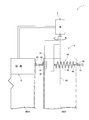
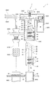
図1に示すように、この超音波フェーズドアレイ検査装置1は、一定の間隔で平行(並列)に配置された多数の管9と、これら管9に垂直な管板91とが溶接された設備に対して、溶接された部分(以下、溶接部92という)の超音波によるフェーズドアレイ法の探傷試験を、前記管9の内部から順次(次々に)行うための検査装置である。前記多数の管9のうち、探傷試験が行われている管94、または、探傷試験が行われようとされている管94を、探傷試験の対象となる管94として、以下では対象管94と称する。所定の管9に探傷試験を行う場合、当該所定の管9は対象管94であるが、当該探傷試験が終われば当該所定の管9は対象管94でなくなり、次の探傷試験の対象となる管9が対象管94となる。
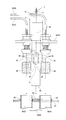
前記超音波フェーズドアレイ検査装置1は、図1および図2に示すように、対象管94に挿入されて当該対象管94の溶接部92に対して探傷試験を行う探傷試験体4と、前記対象管94の軸90回りに探傷試験体4を回転させる駆動機構2と、前記対象管94とは異なる管96に挿入されて固定される治具6とを備える。前記探傷試験体4は、超音波によるフェーズドアレイ法を行うフェーズドアレイ探触子42が内蔵された探傷部41と、この探傷部41を対象管94の内面に押圧する押圧機構45とを有する。
前記探傷試験体4は、その全体が対象管94に挿入される必要がなく、少なくとも探傷部41が対象管94の内部から溶接部92の探傷試験を行える深さまで当該対象管94に挿入されるものであればよい。なお、以下では、対象管94において探傷試験体4が挿入される先側および元側を、それぞれ対象管94の奥側および手前側と称する。
前記押圧機構45は、前記探傷部41を対象管94の内面に押圧するものであれば特に限定されないが、例えば、圧縮ばね46、引張ばね若しくはブラシなど弾性力で押圧するもの(弾性部材)、磁力で押圧するもの、または、気圧若しくは液圧で押圧するものなどである。また、前記押圧機構45は、対象管94の内面に接触する場合、当該接触する部分にローラ48を有することが好ましい。このようなローラ48により、押圧機構45と対象管94の内面との摩擦が低減されるからである。さらに、前記押圧機構45は、その押圧する力が駆動機構2による探傷試験体4の回転を妨げない(回転の速度を極端に低下させない)程度に設定される。前記押圧機構45は、図3に示すように、前記探傷試験体4を構成する長手部材40と前記探傷部41との間に設けられた押圧動力部(例えば、圧縮ばね46またはブラシなどの弾性部材)と、前記探傷部41を対象管94の内面に案内する案内部材49とを有するものでもよい。当該案内部材49は、前記探傷部41を対象管94の内面に対して垂直に案内するものであることが好ましい。
前記駆動機構2は、前記対象管94の軸90回りに探傷試験体4を回転させるものであれば特に限定されないが、例えば、モータである。
前記治具6は、対象管94とは異なる管96に挿入された状態で当該管96に固定されるものであれば特に限定されないが、例えば、当該管96の内部で膨張および収縮し得る膨縮部を先端に有する脚部でもよく、当該管96の内部で機械的に拡張および縮小し得る拡縮部を先端に有する脚部でもよい。
以下、前記超音波フェーズドアレイ検査装置1の使用方法について説明する。
まず、図1に示すように、対象管94に探傷試験体4を挿入する一方で、当該対象管94とは異なる管96に治具6を挿入し、当該管96に治具6を固定する。そして、図2に示すように、対象管94の内部では、押圧機構45により対象管94の内面に探傷部41が押圧される。
次に、駆動機構2により、探傷試験体4を対象管94の軸90回りに回転させる。探傷試験体4は、回転しながらフェーズドアレイ探触子42の超音波によるフェーズドアレイ法で探傷試験を行っていく。この際に、探傷部41は押圧機構45により対象管94の内面に押圧されているので、フェーズドアレイ探触子42と対象管94の内面との近接した状態が維持される。
このように、前記超音波フェーズドアレイ検査装置1によると、対象管94の腐食による減肉などにより内径が変化しても、探傷試験を行っているフェーズドアレイ探触子42と対象管94の内面との近接した状態が維持されるので、高精度に探傷試験を行うことができる。
[実施の形態2]
[実施の形態2]
以下、前記実施の形態1に係る超音波フェーズドアレイ検査装置1よりも高精度に対象試験を行うことが可能な実施の形態2に係る超音波フェーズドアレイ検査装置1について、図面に基づき説明する。本実施の形態2では、前記実施の形態1とは異なる構成に着目して説明するとともに、前記実施の形態1と同一の構成については、同一の符号を付してその説明を省略する。
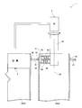
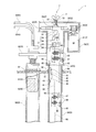
図4に示すように、本実施の形態2に係る超音波フェーズドアレイ検査装置1は、治具6および探傷試験体4を保持する本体5を備える。
駆動機構2は、前記本体5に固定された電動モータ21と、この電動モータ21の出力軸に接続されたピニオン22と、このピニオン22に噛み合うギヤ23とを有する。
前記超音波フェーズドアレイ検査装置1は、駆動機構2と探傷試験体4とを接続する偏心許容継手3を備える。この偏心許容継手3は、駆動機構2の軸心(以下、駆動軸心31と称する)と探傷試験体4の軸心(以下、従動軸心32と称する)とのずれを許容する。前記偏心許容継手3は、駆動軸心31回りの駆動機構2の回転を、従動軸心32回りの探傷試験体4の回転に伝達する(自転に伝達する)ものでもよく、または、駆動軸心31回りの駆動機構2の回転を、駆動軸心31回りの探傷試験体4の回転に伝達する(公転に伝達する)ものでもよい。
前記本体5は、探傷部41の対象管94における深さを調整する調整具7を有する。この調整具7は、一端につまみ71が設けられたボルト72であり、前記本体5に駆動軸心31に沿って形成された雌ネジ孔57に螺合して、当該一端が本体5の外部に位置するとともに、他端が本体5の内部でギヤ23に軸受け24などを介して接続されたものである。
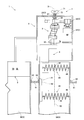
前記探傷試験体4の押圧機構45は、例えば、複数であり、図4では2つの場合を示す。これら複数の押圧機構45のうち、一方は対象管94の奥側に配置され、他方は対象管94の手前側に配置される。すなわち、前記押圧機構45は、探傷部41に対して、対象管94の奥側および手前側に配置されたものである。これら複数の押圧機構45のうち、前記対象管94の手前側に配置されたものは、図4に示すように当該対象管94の内部でもよく、図5に示すように前記本体5の内部でもよい。図4に示す構成は、対象管94のより奥側に溶接部92がある場合の探傷試験に適し、図5に示す構成は、対象管94のより手前側に溶接部92がある場合の探傷試験に適する。
以下、前記超音波フェーズドアレイ検査装置1の使用方法について説明する。
まず、図4および図5に示すように、対象管94に探傷試験体4を挿入する一方で、当該対象管94とは異なる管96に治具6を挿入し、当該管96に治具6を固定する。そして、対象管94の内部では、押圧機構45により対象管94の内面に探傷部41が押圧される。この押圧は、探傷部41に対して対象管94の奥側および手前側の両方からなので、前記実施の形態1に比べて安定している。
対象管94とは異なる管96に治具6を固定した後、探傷部41の対象管94における深さが適切でないことに気付く場合もある。この場合、調整具7のつまみ71を回すことにより、当該深さを調整する。
次に、駆動機構2により、探傷試験体4を対象管94の軸90回りに回転させる。この際に、対象管94の内径によって、駆動機構2の軸心である駆動軸心31と探傷試験体4の軸心である従動軸心32とをずらす必要が生ずる。しかしながら、このずれは偏心許容継手3により許容されるので、駆動機構2から探傷試験体4に回転が適切に伝達される。そして、探傷試験体4は、回転しながらフェーズドアレイ探触子42の超音波によるフェーズドアレイ法で探傷試験を行っていく。この際に、探傷部41は押圧機構45により対象管94の内面に押圧されているので、フェーズドアレイ探触子42と対象管94の内面との近接した状態が維持される。
このように、前記超音波フェーズドアレイ検査装置1によると、対象管94の腐食による減肉などにより内径が変化しても、探傷試験を行っているフェーズドアレイ探触子42と対象管94の内面との近接した状態が安定して維持されるので、より高精度に探傷試験を行うことができる。
また、偏心許容継手3により駆動機構2と探傷試験体4との各軸心31,32のずれが許容されるので、探傷試験体4が対象管94に対して適切に回転し、その結果、より高精度に探傷試験を行うことができる。
さらに、調整具7により探傷部41の対象管94における深さが調整されるので、対象管94の溶接部92と探傷部41との位置関係がより適切になり、その結果、より高精度に探傷試験を行うことができる。
以下、前記実施の形態1および2をより具体的に示した実施例に係る超音波フェーズドアレイ検査装置1について、図6~図9に基づき説明する。本実施例では、前記実施の形態1および2とは異なる構成に着目して説明するとともに、前記実施の形態と同一の構成については、同一の符号を付してその説明を省略する。
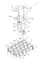
図6および図7に示すように、本実施例に係る超音波フェーズドアレイ検査装置1の本体5は、2つの略直方体52,53を各先端部で連結した二股形状である。これら2つの略直方体52,53のうち、以下では、探傷試験体4を突出させた方を試験体側直方体53と称し、他方の直方体をモータ側直方体52と称し、前記試験体側直方体53とモータ側直方体52とをそれらの先端部で連結している部分を連結部55と称する。
本実施例に係る超音波フェーズドアレイ検査装置1の治具6は、図6および図8に示すように、駆動軸心31に直交する向きで前記試験体側直方体53に取り付けられた長穴保持部材65と、この長穴保持部材65の任意の位置で固定されて探傷試験体4に対して平行な2本の脚部61と、これら2本の脚部61の先端にそれぞれ設けられて膨張および収縮し得る膨縮部62と、これら膨縮部62を膨張および収縮させるためのエアを供給および排出するエアチューブ63とを有する。また、前記脚部61は、それらの長さを調整可能に且つ、長穴保持部材65に形成された長穴の任意の位置で締結可能に構成される。さらに、前記脚部61は、対象管94に隣接する2本の管96にそれぞれ挿入された際に探傷試験体4が前記対象管94に挿入される位置で、前記長穴保持部材65に固定される。
次に、前記超音波フェーズドアレイ検査装置1の前記治具6が対象管94に隣接する管96に挿入されて固定された状態について、図9に基づき説明する。
電動モータ21は、モータ側直方体52に収容されるとともに、当該モータ側直方体52に固定される。前記電動モータ21の出力軸に接続されたピニオン22は、前記モータ側直方体52の先端部に収容される。前記ピニオン22に噛み合うギヤ23は、連結部55および試験体側直方体53の先端部に亘って収容される。ギヤ23の軸受け24は、前記試験体側直方体53の先端部に収容されるとともに、調整具7により駆動軸心31に沿って移動可能に構成される。調整具7のボルト72が螺合する雌ネジ孔57は、試験体側直方体53における駆動軸心31の延長上に形成される。
前記ギヤ23に接続された偏心許容継手3は、試験体側直方体53に収容されるとともに、次の部材33~36を有する。すなわち、前記偏心許容継手3は、前記ギヤ23の軸が駆動側で接続されたフレキシブルカップリング33と、このフレキシブルカップリング33に従動側で接続された従動部材34と、この従動部材34に取り付けられて駆動軸心31に直交する案内ピン35と、この案内ピン35に沿って摺動する摺動部材36とを有する。前記フレキシブルカップリング33が駆動軸心31回りのギヤ23の回転を自転に伝達するものであり、前記従動部材34、案内ピン35および摺動部材36が駆動軸心31回りのギヤ23の回転を公転に伝達するものである。
前記探傷試験体4は、従動軸心32に沿った長手部材40と、この長手部材40を案内ピン35に平行な方向で押圧する押圧機構45と、長手部材40に設けられた探傷部41とを有する。前記長手部材40は、一端部が試験体側直方体53の内部で摺動部材36に取り付けられ、中央部および他端部が試験体側直方体53から突出する。前記押圧機構45は、前記試験体側直方体53の内部および外部にそれぞれ配置される。各押圧機構45は、前記長手部材40に一端が接続された圧縮ばね46と、当該圧縮ばね46の他端に接続されたローラ部材47とを有する。このローラ部材47は、従動軸心32に平行な軸心回りに回転するローラ48を有する。前記探傷部41は、長手部材40の表面近傍に配置されたフェーズドアレイ探触子42と、当該フェーズドアレイ探触子42を覆って対象管94の内面に面し得るウェッジ43と、このウェッジ43の周囲から探傷試験に必要な接触媒体を供給し得る媒体供給穴44とを有する。
以下、前記超音波フェーズドアレイ検査装置1の使用方法について説明する。
まず、図6に示すように、対象管94に探傷試験体4を挿入する一方で、当該対象管94に隣接する管96に治具6の収縮させた膨縮部62を挿入する。次いで、図9に示すように、前記管96の内部で膨縮部62を膨張させることで、当該管96に治具6を固定する。そして、対象管94の内部では、押圧機構45により対象管94の内面に探傷部41が押圧される。
対象管94に隣接する管96に治具6を固定した後、探傷部41の対象管94における深さが適切でないことに気付く場合もある。例えば、探傷部41に電気的に接続されたモニタ(図示省略)で探傷試験の状況を確認した場合などである。この場合、調整具7のつまみ71を回すことにより、当該深さを調整する。
次に、駆動機構2により、探傷試験体4を対象管94の軸90回りに回転させる。この際に、対象管94の内径によって、駆動機構2の軸心である駆動軸心31と探傷試験体4の軸心である従動軸心32とをずらす必要が生ずる。しかしながら、このずれは偏心許容継手3により許容されるので、駆動機構2から探傷試験体4に回転が適切に伝達される。特に、この偏心許容継手3は、駆動機構2の回転を自転および公転に伝達するものであるから、前記ずれが大きくても、駆動機構2から探傷試験体4に回転が適切に伝達される。そして、探傷試験体4は、回転しながらフェーズドアレイ探触子42の超音波によるフェーズドアレイ法で探傷試験を行っていく。この際に、探傷部41は押圧機構45により対象管94の内面に押圧されているので、フェーズドアレイ探触子42と対象管94の内面との近接した状態が維持される。対象管94の内面とウェッジ43との間隔が数μm~数百μm生ずるが、この間隔には媒体供給穴44から供給された接触媒体が毛細管現象により満たされる。そして、探傷試験がより適切に行われる。
このように、前記超音波フェーズドアレイ検査装置1によると、前記実施の形態1および2で奏する効果に加えて、次の効果も奏する。すなわち、駆動機構2の回転を自転および公転に伝達する偏心許容継手3により、各軸心31,32のずれが一層適切に許容されるので、探傷試験体4が対象管94に対して一層適切に回転し、その結果、一層高精度に探傷試験を行うことができる。
ところで、前記実施の形態1および2並びに実施例では、管板91から管9が手前側に突出している設備に使用するものとして図示したが、管板91から管9が手前側に突出していない設備に使用するものであってもよい。
また、前記実施の形態2および実施例では、探傷部41に対して対象管94の奥側および手前側に配置された押圧機構45が同一のものとして図示したが、異なるものであってもよい。これら押圧機構45は、探傷部41を対象管94の内面に深さ方向で均一に押圧するものであることが好ましい。探傷部41が深さ方向で均一に押圧されることで、一層高精度に探傷試験を行うことができるからである。なお、前記試験体側直方体53の内部に配置された押圧機構45であれば、押圧機構45の弾性部材が引張ばねであっても、当該引張ばねにより探傷部41が長手部材40を介して対象管94の内面に引っ張られるので、探傷部41を対象管94の内面に押圧することが可能である。
また、前記実施の形態1および2並びに実施例は、押圧機構45が1つまたは2つの場合について説明したが、3つ以上であってもよい。なお、押圧機構45が小型化可能な場合は、図3に示すように、対象管94の内面を押圧しない構成であることが好ましい。図3で圧縮ばね46として示した押圧動力部は、圧縮ばね46などの弾性部材に限られず、探傷部41を対象管94の内面に向けて移動させ得るものであればよい。
加えて、前記実施の形態1および2並びに実施例は、全ての点で例示であって制限的なものではない。本発明の範囲は、前述した説明ではなく請求の範囲によって示され、請求の範囲と均等の意味および範囲内での全ての変更が含まれることが意図される。前記実施の形態1および2並びに実施例で説明した構成のうち「課題を解決するための手段」での第1の発明として記載した構成以外については、任意の構成であり、適宜削除および変更することが可能である。
Claims (5)
- 並列に配置された複数の管に対して超音波によるフェーズドアレイ法で溶接部の探傷試験を順次行う超音波フェーズドアレイ検査装置であって、
前記管のうち探傷試験の対象となる対象管に挿入されて当該対象管の溶接部に対して探傷試験を行う探傷試験体と、
前記対象管の軸回りに探傷試験体を回転させる駆動機構と、
前記対象管とは異なる管に挿入されて固定される治具とを備え、
前記探傷試験体が、
超音波によるフェーズドアレイ法を行うフェーズドアレイ探触子が内蔵された探傷部と、
前記探傷部を対象管の内面に押圧する押圧機構とを有することを特徴とする超音波フェーズドアレイ検査装置。 - 前記探傷試験体の押圧機構が、探傷部に対して、対象管の奥側および手前側に配置されたものであることを特徴とする請求項1に記載の超音波フェーズドアレイ検査装置。
- 前記探傷試験体の押圧機構が、
弾性力により探傷部を対象管の内面に向けて移動させ得る押圧動力部と、
前記探傷部を対象管の内面に案内する案内部材とを有することを特徴とする請求項1または2に記載の超音波フェーズドアレイ検査装置。 - 前記駆動機構と探傷試験体との各軸心のずれを許容して接続する偏心許容継手を備えることを特徴とする請求項1または2に記載の超音波フェーズドアレイ検査装置。
- 前記治具および探傷試験体を保持する本体を備え、
前記本体が、探傷部の対象管における深さを調整する調整具を有することを特徴とする請求項1または2に記載の超音波フェーズドアレイ検査装置。
Priority Applications (3)
| Application Number | Priority Date | Filing Date | Title |
|---|---|---|---|
| CN201980096205.5A CN113841047A (zh) | 2019-05-29 | 2019-12-10 | 超声波相控阵检查装置 |
| US17/614,465 US12085538B2 (en) | 2019-05-29 | 2019-12-10 | Ultrasonic phased array detection device for flaw detection of parallel tubes |
| SA521430983A SA521430983B1 (ar) | 2019-05-29 | 2021-11-28 | جهاز كشف بمصفوفة بأطوار فوق صوتية |
Applications Claiming Priority (2)
| Application Number | Priority Date | Filing Date | Title |
|---|---|---|---|
| JP2019099852A JP7308080B2 (ja) | 2019-05-29 | 2019-05-29 | 超音波フェーズドアレイ検査装置 |
| JP2019-099852 | 2019-05-29 |
Publications (1)
| Publication Number | Publication Date |
|---|---|
| WO2020240896A1 true WO2020240896A1 (ja) | 2020-12-03 |
Family
ID=73548655
Family Applications (1)
| Application Number | Title | Priority Date | Filing Date |
|---|---|---|---|
| PCT/JP2019/048308 Ceased WO2020240896A1 (ja) | 2019-05-29 | 2019-12-10 | 超音波フェーズドアレイ検査装置 |
Country Status (5)
| Country | Link |
|---|---|
| US (1) | US12085538B2 (ja) |
| JP (1) | JP7308080B2 (ja) |
| CN (1) | CN113841047A (ja) |
| SA (1) | SA521430983B1 (ja) |
| WO (1) | WO2020240896A1 (ja) |
Families Citing this family (2)
| Publication number | Priority date | Publication date | Assignee | Title |
|---|---|---|---|---|
| JP2023103502A (ja) * | 2022-01-14 | 2023-07-27 | 日立造船株式会社 | 超音波フェーズドアレイ検査装置及びこれを使用する超音波フェーズドアレイ検査方法 |
| CN118032939B (zh) * | 2024-04-15 | 2024-07-30 | 葫芦岛北检科技有限公司 | 一种采用声磁组合技术检测奥氏体焊缝的方法 |
Citations (3)
| Publication number | Priority date | Publication date | Assignee | Title |
|---|---|---|---|---|
| JPS6293658A (ja) * | 1985-10-18 | 1987-04-30 | Nichizou Tec:Kk | 管端溶接部の超音波探傷用治具 |
| US20090193899A1 (en) * | 2008-02-25 | 2009-08-06 | Battelle Memorial Institute | System and process for ultrasonic characterization of deformed structures |
| JP2016191571A (ja) * | 2015-03-31 | 2016-11-10 | 日立造船株式会社 | 超音波検査装置 |
Family Cites Families (3)
| Publication number | Priority date | Publication date | Assignee | Title |
|---|---|---|---|---|
| JPH028211Y2 (ja) * | 1980-03-07 | 1990-02-27 | ||
| JPS59149055U (ja) * | 1983-03-25 | 1984-10-05 | 株式会社トキメック | 超音波探傷装置 |
| CN202533416U (zh) | 2012-02-27 | 2012-11-14 | 西南交通大学 | 便携式实心车轴超声探伤装置 |
-
2019
- 2019-05-29 JP JP2019099852A patent/JP7308080B2/ja active Active
- 2019-12-10 WO PCT/JP2019/048308 patent/WO2020240896A1/ja not_active Ceased
- 2019-12-10 CN CN201980096205.5A patent/CN113841047A/zh active Pending
- 2019-12-10 US US17/614,465 patent/US12085538B2/en active Active
-
2021
- 2021-11-28 SA SA521430983A patent/SA521430983B1/ar unknown
Patent Citations (3)
| Publication number | Priority date | Publication date | Assignee | Title |
|---|---|---|---|---|
| JPS6293658A (ja) * | 1985-10-18 | 1987-04-30 | Nichizou Tec:Kk | 管端溶接部の超音波探傷用治具 |
| US20090193899A1 (en) * | 2008-02-25 | 2009-08-06 | Battelle Memorial Institute | System and process for ultrasonic characterization of deformed structures |
| JP2016191571A (ja) * | 2015-03-31 | 2016-11-10 | 日立造船株式会社 | 超音波検査装置 |
Also Published As
| Publication number | Publication date |
|---|---|
| US20220236233A1 (en) | 2022-07-28 |
| US12085538B2 (en) | 2024-09-10 |
| JP7308080B2 (ja) | 2023-07-13 |
| SA521430983B1 (ar) | 2023-12-05 |
| JP2020193878A (ja) | 2020-12-03 |
| CN113841047A (zh) | 2021-12-24 |
Similar Documents
| Publication | Publication Date | Title |
|---|---|---|
| US6877894B2 (en) | Self-aligning apparatus for acoustic thermography | |
| JP4881423B2 (ja) | 着脱式探触子を備えた検査装置 | |
| US7694564B2 (en) | Boiler tube inspection probe with centering mechanism and method of operating the same | |
| WO2020240896A1 (ja) | 超音波フェーズドアレイ検査装置 | |
| CN103453862B (zh) | 用于检查管子的设备和方法 | |
| JP6760727B2 (ja) | 実質的に丸い穴についての検査システム用のプローブ | |
| US8146430B2 (en) | Method and apparatus for conveying an ultrasonic sensor about an outer peripheral surface of a tube | |
| GB2122713A (en) | Apparatus for working on the interior of pipes | |
| JP6206694B1 (ja) | 管肉厚測定装置 | |
| JP6258025B2 (ja) | 狭隘部サンプル採取ヘッド、狭隘部サンプル採取方法および余寿命診断方法 | |
| CN112055810B (zh) | 用于wh型骨架膨胀工具的疲劳测试装置 | |
| CN111474247A (zh) | 一种晶片阵列角度可调式相控阵超声波探头及其组装和检测方法 | |
| JP4902444B2 (ja) | 渦流探傷用マルチコイルプローブ装置 | |
| JP2013148477A (ja) | 管径測定装置及び管径検査方法 | |
| JP6489901B2 (ja) | 超音波検査装置 | |
| CN112557518B (zh) | 一种检测管道内壁的环形探头对中机构及检测系统 | |
| CN113252798B (zh) | 一种小径管超声检测用扫查器 | |
| JPH0886774A (ja) | 超音波探傷試験装置 | |
| JP5813735B2 (ja) | 配管の非破壊検査装置 | |
| US20220317093A1 (en) | Scanner having flexible probe | |
| JP2015108520A (ja) | 拡管部検査装置 | |
| JP6636255B2 (ja) | 測定装置の補助具 | |
| KR102847670B1 (ko) | 보일러 튜브용 감육 검사장치 | |
| CN121917655A (zh) | 一种管道热熔接头缺陷用相控阵换能检测装置及方法 | |
| JPH0618910U (ja) | 超音波探触子の押し付け機構 |
Legal Events
| Date | Code | Title | Description |
|---|---|---|---|
| 121 | Ep: the epo has been informed by wipo that ep was designated in this application |
Ref document number: 19930687 Country of ref document: EP Kind code of ref document: A1 |
|
| NENP | Non-entry into the national phase |
Ref country code: DE |
|
| 122 | Ep: pct application non-entry in european phase |
Ref document number: 19930687 Country of ref document: EP Kind code of ref document: A1 |
|
| WWG | Wipo information: grant in national office |
Ref document number: 521430983 Country of ref document: SA |