WO2020240805A1 - ターボチャージャのシール構造およびターボチャージャ - Google Patents
ターボチャージャのシール構造およびターボチャージャ Download PDFInfo
- Publication number
- WO2020240805A1 WO2020240805A1 PCT/JP2019/021668 JP2019021668W WO2020240805A1 WO 2020240805 A1 WO2020240805 A1 WO 2020240805A1 JP 2019021668 W JP2019021668 W JP 2019021668W WO 2020240805 A1 WO2020240805 A1 WO 2020240805A1
- Authority
- WO
- WIPO (PCT)
- Prior art keywords
- wall surface
- plate
- exhaust gas
- turbine housing
- turbocharger
- Prior art date
- Legal status (The legal status is an assumption and is not a legal conclusion. Google has not performed a legal analysis and makes no representation as to the accuracy of the status listed.)
- Ceased
Links
Images







Classifications
-
- F—MECHANICAL ENGINEERING; LIGHTING; HEATING; WEAPONS; BLASTING
- F02—COMBUSTION ENGINES; HOT-GAS OR COMBUSTION-PRODUCT ENGINE PLANTS
- F02B—INTERNAL-COMBUSTION PISTON ENGINES; COMBUSTION ENGINES IN GENERAL
- F02B37/00—Engines characterised by provision of pumps driven at least for part of the time by exhaust
- F02B37/12—Control of the pumps
- F02B37/24—Control of the pumps by using pumps or turbines with adjustable guide vanes
-
- F—MECHANICAL ENGINEERING; LIGHTING; HEATING; WEAPONS; BLASTING
- F01—MACHINES OR ENGINES IN GENERAL; ENGINE PLANTS IN GENERAL; STEAM ENGINES
- F01D—NON-POSITIVE DISPLACEMENT MACHINES OR ENGINES, e.g. STEAM TURBINES
- F01D11/00—Preventing or minimising internal leakage of working-fluid, e.g. between stages
- F01D11/003—Preventing or minimising internal leakage of working-fluid, e.g. between stages by packing rings; Mechanical seals
-
- F—MECHANICAL ENGINEERING; LIGHTING; HEATING; WEAPONS; BLASTING
- F01—MACHINES OR ENGINES IN GENERAL; ENGINE PLANTS IN GENERAL; STEAM ENGINES
- F01D—NON-POSITIVE DISPLACEMENT MACHINES OR ENGINES, e.g. STEAM TURBINES
- F01D17/00—Regulating or controlling by varying flow
- F01D17/10—Final actuators
- F01D17/12—Final actuators arranged in stator parts
- F01D17/14—Final actuators arranged in stator parts varying effective cross-sectional area of nozzles or guide conduits
- F01D17/16—Final actuators arranged in stator parts varying effective cross-sectional area of nozzles or guide conduits by means of nozzle vanes
- F01D17/165—Final actuators arranged in stator parts varying effective cross-sectional area of nozzles or guide conduits by means of nozzle vanes for radial flow, i.e. the vanes turning around axes which are essentially parallel to the rotor centre line
-
- F—MECHANICAL ENGINEERING; LIGHTING; HEATING; WEAPONS; BLASTING
- F01—MACHINES OR ENGINES IN GENERAL; ENGINE PLANTS IN GENERAL; STEAM ENGINES
- F01D—NON-POSITIVE DISPLACEMENT MACHINES OR ENGINES, e.g. STEAM TURBINES
- F01D25/00—Component parts, details, or accessories, not provided for in, or of interest apart from, other groups
- F01D25/24—Casings; Casing parts, e.g. diaphragms, casing fastenings
-
- F—MECHANICAL ENGINEERING; LIGHTING; HEATING; WEAPONS; BLASTING
- F02—COMBUSTION ENGINES; HOT-GAS OR COMBUSTION-PRODUCT ENGINE PLANTS
- F02B—INTERNAL-COMBUSTION PISTON ENGINES; COMBUSTION ENGINES IN GENERAL
- F02B39/00—Component parts, details, or accessories relating to, driven charging or scavenging pumps, not provided for in groups F02B33/00 - F02B37/00
-
- F—MECHANICAL ENGINEERING; LIGHTING; HEATING; WEAPONS; BLASTING
- F05—INDEXING SCHEMES RELATING TO ENGINES OR PUMPS IN VARIOUS SUBCLASSES OF CLASSES F01-F04
- F05D—INDEXING SCHEME FOR ASPECTS RELATING TO NON-POSITIVE-DISPLACEMENT MACHINES OR ENGINES, GAS-TURBINES OR JET-PROPULSION PLANTS
- F05D2220/00—Application
- F05D2220/40—Application in turbochargers
-
- F—MECHANICAL ENGINEERING; LIGHTING; HEATING; WEAPONS; BLASTING
- F05—INDEXING SCHEMES RELATING TO ENGINES OR PUMPS IN VARIOUS SUBCLASSES OF CLASSES F01-F04
- F05D—INDEXING SCHEME FOR ASPECTS RELATING TO NON-POSITIVE-DISPLACEMENT MACHINES OR ENGINES, GAS-TURBINES OR JET-PROPULSION PLANTS
- F05D2240/00—Components
- F05D2240/10—Stators
- F05D2240/12—Fluid guiding means, e.g. vanes
- F05D2240/128—Nozzles
-
- F—MECHANICAL ENGINEERING; LIGHTING; HEATING; WEAPONS; BLASTING
- F05—INDEXING SCHEMES RELATING TO ENGINES OR PUMPS IN VARIOUS SUBCLASSES OF CLASSES F01-F04
- F05D—INDEXING SCHEME FOR ASPECTS RELATING TO NON-POSITIVE-DISPLACEMENT MACHINES OR ENGINES, GAS-TURBINES OR JET-PROPULSION PLANTS
- F05D2240/00—Components
- F05D2240/55—Seals
-
- F—MECHANICAL ENGINEERING; LIGHTING; HEATING; WEAPONS; BLASTING
- F05—INDEXING SCHEMES RELATING TO ENGINES OR PUMPS IN VARIOUS SUBCLASSES OF CLASSES F01-F04
- F05D—INDEXING SCHEME FOR ASPECTS RELATING TO NON-POSITIVE-DISPLACEMENT MACHINES OR ENGINES, GAS-TURBINES OR JET-PROPULSION PLANTS
- F05D2240/00—Components
- F05D2240/55—Seals
- F05D2240/58—Piston ring seals
-
- Y—GENERAL TAGGING OF NEW TECHNOLOGICAL DEVELOPMENTS; GENERAL TAGGING OF CROSS-SECTIONAL TECHNOLOGIES SPANNING OVER SEVERAL SECTIONS OF THE IPC; TECHNICAL SUBJECTS COVERED BY FORMER USPC CROSS-REFERENCE ART COLLECTIONS [XRACs] AND DIGESTS
- Y02—TECHNOLOGIES OR APPLICATIONS FOR MITIGATION OR ADAPTATION AGAINST CLIMATE CHANGE
- Y02T—CLIMATE CHANGE MITIGATION TECHNOLOGIES RELATED TO TRANSPORTATION
- Y02T10/00—Road transport of goods or passengers
- Y02T10/10—Internal combustion engine [ICE] based vehicles
- Y02T10/12—Improving ICE efficiencies
Definitions
- the present disclosure relates to a seal structure for sealing a gap formed in a turbine housing in a turbocharger, and a turbocharger having the above seal structure.
- variable displacement turbocharger is known as a turbocharger that supercharges intake air by using the energy of the exhaust gas of an engine (see, for example, Patent Document 1).
- the variable displacement turbocharger enhances the supercharging effect by changing the flow velocity and pressure of the exhaust gas sent to the turbine wheel by adjusting the flow of exhaust gas from the scroll flow path of the turbine housing to the turbine wheel with a variable nozzle mechanism. It is a thing.
- variable nozzle mechanism generally includes a nozzle vane (variable nozzle) provided in the exhaust gas flow path that guides the exhaust gas from the scroll flow path to the turbine wheel, and is housed inside the turbine housing and rotatably supports the nozzle vane. It includes an annular nozzle mount and an annular nozzle plate that defines an exhaust gas flow path between the nozzle mounts.
- Patent Document 1 describes a tubular portion housed in a turbine housing, a nozzle plate having a nozzle portion extending radially outward from one end of the tubular portion, the other end surface of the tubular portion, and the inside of the turbine housing.
- a seal structure including a seal ring for sealing between a wall surface (step surface) and a wall surface (step surface) is disclosed.
- the seal ring described in Patent Document 1 is made of an annular body having a U-shaped or V-shaped cross section, and is configured such that the opening side of the cross section faces the radial direction.
- one of the two legs defined by the U-shaped or V-shaped cross section is in contact with the other end surface of the tubular portion, and the other leg is inside the turbine housing.
- the wall surface step surface
- the other end surface of the tubular portion and the inner wall surface (step surface) of the turbine housing are sealed.
- the turbine housing and nozzle plate in the seal structure described in Patent Document 1 are deformed by receiving the heat of the exhaust gas during the operation of the turbocharger. A difference is generated, and the relative positional relationship between the turbine housing and the nozzle plate changes due to the above difference.
- the seal ring whose legs are in contact with each of the turbine housing and the nozzle plate is deformed or the legs slide with respect to the turbine housing or the nozzle plate each time the relative positional relationship changes. ..
- the seal ring may deteriorate and the elastic force may decrease, and by repeating the sliding of the leg portion, the leg portion may be worn.
- the seal ring receives the heat of the exhaust gas during the operation of the turbocharger, and may deteriorate due to repeated thermal expansion and contraction, resulting in a decrease in elastic force. Therefore, the seal ring in the above seal structure may not exhibit stable sealing performance for a long period of time.
- an object of at least one embodiment of the present invention is to provide a turbocharger sealing structure capable of exhibiting stable sealing performance for a long period of time.
- the seal structure of the turbocharger is A turbine housing with a scroll flow path and With the nozzle mount supported inside the turbine housing, A nozzle plate that defines an exhaust gas flow path that guides exhaust gas from the scroll flow path to the turbine wheel between the nozzle mount and the nozzle plate, and has a flow path wall surface that defines the exhaust gas flow path on one side in the thickness direction.
- a nozzle plate including an annular plate portion and a tubular portion extending from an inner peripheral end portion of a back surface of the annular plate portion located on the other side in the thickness direction toward the first inner wall surface of the turbine housing.
- the above sealing device A first plate member having one surface that comes into contact with the end surface of the tubular portion, and It is a sealing member that seals between the other surface of the first plate member and the first inner wall surface, and is configured to urge the first plate member toward the end surface of the tubular portion. Including a sealing member.
- the first plate member is supported between the seal member and the nozzle plate by being urged by the seal member toward the end surface of the tubular portion of the nozzle plate. Therefore, one surface of the first plate member is swingable with respect to the end surface of the tubular portion.
- the nozzle plate is slid with respect to the first plate member, so that the relative surface between the first inner wall surface of the turbine housing and the other surface of the first plate member is obtained. It is possible to suppress changes in the positional relationship.
- the first plate member blocks (heat shields) the exhaust gas flowing from the scroll flow path and the heat from the nozzle plate so that it is not transmitted to the seal member, so that thermal expansion and contraction of the seal member are suppressed.
- deterioration of the sealing performance due to fatigue of the sealing member can be suppressed. Therefore, according to the seal structure of the turbocharger, stable sealing performance can be exhibited for a long period of time.
- the turbocharger seal structure according to (1) above, wherein the first plate member extends in a direction intersecting the first inner wall surface.
- a radial plate portion extending toward the second inner wall surface of the housing is included, and the outer end surface of the radial plate portion is configured to be in contact with the second inner wall surface.
- the outer end surface of the radial plate portion is in contact with the second inner wall surface of the turbine housing, so that the first plate member is radially outward when it receives the heat of the exhaust gas. Growth is restricted. As a result, the amount of thermal deformation in the radial direction of the turbine housing and the first plate member when receiving the heat of the exhaust gas can be made uniform. In the seal structure, the amount of thermal deformation in the radial direction of the turbine housing and the first plate member is made uniform so that the first inner wall surface of the turbine housing and the other surface of the first plate member when the heat of the exhaust gas is received are aligned.
- the turbocharger seal structure according to (1) or (2) is configured such that the seal member is in contact with the first inner wall surface.
- the sealing member is configured to be in contact with the first inner wall surface, so that the other surface of the first plate member and the first inner wall surface can be sealed. ..
- the turbocharger seal structure according to (1) or (2) above, wherein the seal device is a second plate member having one surface in contact with the first inner wall surface.
- the seal member is configured to come into contact with the other surface of the second plate member.
- the second plate member is used to remove the seal member from the turbine housing. It can block heat (heat shield). By blocking the heat from the turbine housing, it is possible to suppress thermal expansion and contraction of the sealing member, and by extension, deterioration of sealing performance due to fatigue of the sealing member can be suppressed.
- the turbocharger seal structure according to any one of (1) to (4) above, and the first plate member intersects the first inner wall surface.
- a radial plate portion extending in the direction toward the second inner wall surface of the turbine housing, and an axial plate portion extending from the inner end portion of the radial plate portion toward the first inner wall surface side. Includes part and.
- the first plate member since the first plate member includes the axial plate portion extending from the inner end portion of the radial plate portion toward the first inner wall surface side, the first plate member is formed by the axial plate portion.
- the turbocharger seal structure according to any one of (1) to (5) above, wherein the seal device is attached to the outer peripheral surface of the tubular portion.
- the plate member further includes a third plate member extending toward the second inner wall surface of the turbine housing extending in a direction intersecting the first inner wall surface.
- the sealing device since the sealing device includes the third plate member extending toward the second inner wall surface of the turbine housing, the nozzle plate and the second inner wall surface of the turbine housing are provided by the third plate member.
- the flow rate of the exhaust gas flowing through the gap toward the seal member can be suppressed.
- the amount of heat energy applied to the seal member from the exhaust gas can be reduced, and the thermal expansion and contraction of the seal member can be suppressed.
- the turbocharger seal structure according to any one of (1) to (6) above, and the cross-sectional shape of the seal member is a U shape having an opening on the outer side in the radial direction. , V-shaped, or J-shaped.
- the cross-sectional shape of the seal member is formed into a U-shape, a V-shape, or a J-shape having an opening on the outer side in the radial direction.
- the opening of the sealing member faces the scroll flow path side. Therefore, since the opening of the sealing member is widened by the pressure of the exhaust gas in the scroll flow path, it is possible to effectively seal between the end surface of the tubular portion and the first inner wall surface.
- the turbocharger seal structure according to any one of (1) to (7) above, wherein the turbine housing intersects the first inner wall surface.
- the second inner wall surface extending so as to have a gap between the nozzle plate and the outer peripheral surface of the tubular portion and the second inner wall surface extending in a direction intersecting the second inner wall surface,
- the second inner wall surface and the third inner wall surface of the turbine housing, and the nozzle including a third inner wall surface configured to have a gap between the annular plate portion of the nozzle plate and the back surface thereof.
- At least one groove extending along the circumferential direction was formed on at least one of the outer peripheral surface of the tubular portion of the plate and the back surface of the annular plate portion.
- At least one of the second inner wall surface and the third inner wall surface of the turbine housing, the outer peripheral surface of the tubular portion of the nozzle plate, and the back surface of the annular plate portion is in the circumferential direction. Since at least one groove extending along the groove is formed, the exhaust gas flowing from the scroll flow path toward the seal member is expanded in at least one groove (expansion chamber) to increase the pressure loss, thereby sealing. The flow rate of the exhaust gas flowing toward the member can be suppressed. By suppressing the flow rate of the exhaust gas flowing toward the seal member, the amount of heat energy applied to the seal member from the exhaust gas can be reduced, and the thermal expansion and contraction of the seal member can be suppressed.
- the turbocharger seal structure according to (8) above includes a third inner wall surface side groove portion formed on the third inner wall surface.
- the nozzle plate further includes a nozzle plate-side protruding portion that protrudes from the back surface into the inside of the third inner wall surface side groove portion.
- the nozzle plate since the nozzle plate includes a nozzle plate side projecting portion protruding from the back surface into the inside of the third inner wall surface side groove portion, the nozzle plate side projecting into the inside of the third inner wall surface side groove portion.
- turbocharger seal structure according to (8) or (9) above, wherein at least one groove is a back surface gutter formed on the back surface of the annular plate portion.
- the turbine housing further includes a housing-side projecting portion that projects from the third inner wall surface into the back surface gutter portion.
- the turbine housing since the turbine housing includes a housing-side protrusion protruding from the third inner wall surface to the inside of the back-side gutter, the turbine housing is provided by the housing-side protrusion that protrudes inside the back-side gutter.
- the turbocharger according to at least one embodiment of the present invention is Turbine wheel and The turbocharger seal structure according to any one of (1) to (10) above is provided.
- a turbocharger sealing structure capable of exhibiting stable sealing performance for a long period of time is provided.
- expressions such as “same”, “equal”, and “homogeneous” that indicate that things are in the same state not only represent exactly the same state, but also have tolerances or differences to the extent that the same function can be obtained. It shall also represent the state of existence.
- an expression representing a shape such as a quadrangular shape or a cylindrical shape not only represents a shape such as a quadrangular shape or a cylindrical shape in a geometrically strict sense, but also an uneven portion or chamfering within a range in which the same effect can be obtained.
- the shape including the part and the like shall also be represented.
- the expression “comprising”, “including”, or “having” one component is not an exclusive expression excluding the existence of another component.
- the same reference numerals may be given to the same configurations, and the description thereof may be omitted.
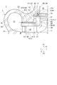
- FIG. 1 is a schematic cross-sectional view including an axis of a turbocharger having a seal structure according to an embodiment of the present invention.
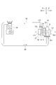
- FIG. 2 is a schematic configuration diagram of an engine including a turbocharger according to an embodiment of the present invention.
- the seal structure 1 according to some embodiments is mounted on the turbocharger 10 as shown in FIG.
- the turbocharger 10 (variable capacity type turbocharger) according to some embodiments includes a turbine wheel 11, a turbine housing 3 for accommodating the turbine wheel 11, a rotating shaft 12, and a rotary shaft 12. It includes a bearing 13 that rotatably supports the rotary shaft 12, a bearing housing 14 that houses the bearing 13 inside, and a variable nozzle device 15 that is a combination of the turbine housing 3 and the bearing housing 14 and is mounted inside.
- the turbocharger 10 further includes a compressor wheel 16 and a compressor housing 17 that houses the compressor wheel 16 inside.
- the direction in which the axis LA of the turbine housing 3 extends is defined as the axial direction X
- the direction orthogonal to the axis LA is defined as the radial direction Y.
- the side where the turbine housing 3 is located with respect to the bearing housing 14 is one side X1
- the side where the compressor housing 17 is located with respect to the bearing housing 14 is the other side. It is the side X2.
- the compressor housing 17 is arranged on the side opposite to the turbine housing 3 with the bearing housing 14 in the axial direction X.
- Each of the turbine housing 3 and the compressor housing 17 is connected and fixed to the bearing housing 14 by fastening members such as bolts and V-clamps.
- the rotating shaft 12 has a longitudinal direction along the axial direction X.
- the turbine wheel 11 is mechanically connected to the end 121 of the one side X1 in the longitudinal direction
- the compressor wheel 16 is mechanically connected to the end 122 of the other side X2 in the longitudinal direction.
- the turbine wheel 11 is provided coaxially with the compressor wheel 16.
- the compressor wheel 16 is provided in a supply line 19 that supplies air (combustion gas) to the engine 18 (combustion device).
- the turbine wheel 11 is provided on a discharge line 20 that discharges exhaust gas from the engine 18.
- the turbocharger 10 rotates the turbine wheel 11 by the exhaust gas introduced from the engine 18 (combustion device) through the discharge line 20 into the inside of the turbine housing 3. Since the compressor wheel 16 is mechanically connected to the turbine wheel 11 via the rotating shaft 12, it rotates in conjunction with the rotation of the turbine wheel 11. By rotating the compressor wheel 16, the turbocharger 10 compresses the air (combustion gas) introduced into the compressor housing 17 through the supply line 19 and sends it to the engine 18 described above.
- the turbine housing 3 rotates an exhaust gas introduction port 301 for introducing exhaust gas from the outside in the radial direction Y into the inside of the turbine housing 3 and a turbine wheel 11. It has an exhaust gas discharge port 302 for discharging exhaust gas to the outside of the turbine housing 3 along the axial direction X.
- the compressor housing 17 passes through an air intake port 171 for introducing air from the outside of the compressor housing 17 along the axial direction X and a compressor wheel 16 as shown in FIG. It has an air supply port 172 for discharging the generated air to the outside of the compressor housing 17 along the radial direction Y and sending it to the engine 18.
- the turbine housing 3 includes a wheel accommodating chamber 34 for accommodating the turbine wheel 11, a scroll flow path 31 for sending the exhaust gas introduced from the exhaust gas introduction port 301 to the wheel accommodating chamber 34, and a wheel. It has an exhaust gas discharge flow path 33 for sending exhaust gas from the accommodation chamber 34 to the exhaust gas discharge port 302.
- the wheel accommodating chamber 34 accommodates the turbine wheel 11 in a rotatable state.
- the scroll flow path 31 has a spiral shape that surrounds the circumference of the wheel accommodating chamber 34 (outside Y in the radial direction).
- the scroll flow path 31 is provided on the upstream side of the wheel accommodating chamber 34 in the flow direction of the exhaust gas, and communicates with the exhaust gas introduction port 301 and the wheel accommodating chamber 34.
- the scroll flow path 31 is defined by the scroll inner wall surface 351 of the scroll forming portion 35.
- the turbine housing 3 includes a scroll forming portion 35, and the scroll forming portion 35 has a scroll inner wall surface 351 defining a scroll flow path 31.
- the exhaust gas discharge flow path 33 is provided on one side X1 of the wheel accommodating chamber 34 and extends along the axial direction X.
- the exhaust gas discharge flow path 33 is provided on the downstream side of the wheel storage chamber 34 in the flow direction of the exhaust gas, and communicates with the wheel storage chamber 34 and the exhaust gas discharge port 302.
- the exhaust gas discharge flow path 33 is defined by the bore inner wall surface 361 (inner peripheral surface) of the tubular bore forming portion 36 extending along the axial direction X.
- the turbine housing 3 includes a bore forming portion 36, and the bore forming portion 36 has a bore inner wall surface 361 that defines an exhaust gas discharge flow path 33.
- the exhaust gas discharge port 302 described above is open to the downstream opening end portion 362 of the bore forming portion 36.
- the turbine housing 3 includes a first inner wall surface 371 extending along a direction intersecting (orthogonal) with the axis LA, and a second inner wall surface 372 extending along the axis LA. It has a third inner wall surface 373 extending along a direction intersecting (orthogonal) with the axis LA.
- each of the first inner wall surface 371, the second inner wall surface 372, and the third inner wall surface 373 is formed at the upstream opening end portion 363 of the bore forming portion 36.
- the first inner wall surface 371, the second inner wall surface 372, and the third inner wall surface 373 may be formed in addition to the upstream opening end portion 363.
- the third inner wall surface 373 is an end surface of the upstream side opening end portion 363.
- the second inner wall surface 372 is an inner wall surface connected to the third inner wall surface 373 and the first inner wall surface 371.
- the first inner wall surface 371 is a bottom surface of a step portion 37 provided recessed on one side X1 of the third inner wall surface 373, and is a stepped surface connected to the second inner wall surface 372 and the bore inner wall surface 361.
- variable nozzle device 15 is provided so as to surround the periphery (diameter Y outside) of the wheel accommodating chamber 34 for accommodating the turbine wheel 11.
- the variable nozzle device 15 is provided inside the scroll flow path 31 in the radial direction Y.
- the variable nozzle device 15 is configured to define an exhaust gas flow path 32 (nozzle flow path) that guides the exhaust gas from the scroll flow path 31 to the turbine wheel 11.
- the exhaust gas flow path 32 is provided on the upstream side of the wheel accommodating chamber 34 in the flow direction of the exhaust gas, and communicates with the scroll flow path 31 and the wheel accommodating chamber 34. Further, the variable nozzle device 15 is configured so that the flow of exhaust gas from the scroll flow path 31 to the turbine wheel 11 can be adjusted by the nozzle vanes 21.
- the variable nozzle device 15 includes a nozzle mount 4, a nozzle plate 5, and at least one nozzle vane 21 provided in the above-mentioned exhaust gas flow path 32 defined by the nozzle mount 4 and the nozzle plate 5.
- the nozzle plate 5 is provided with at least one nozzle support 22 that supports the nozzle plate 5 at a distance from the nozzle mount 4, and a variable nozzle mechanism 23 that is configured to be able to adjust the blade angle of at least one nozzle vane 21.
- the nozzle mount 4 and the nozzle plate 5 are supported inside the turbine housing 3.
- the exhaust gas flow path 32 described above is defined by the nozzle mount 4 and the nozzle plate 5.
- the nozzle mount 4 is an annular body extending along a direction intersecting (orthogonal) with the axis LA.
- the nozzle mount 4 has a bearing-side flow path wall surface 42 that defines a part of the exhaust gas flow path 32 on one side (one side X1) in the thickness direction.
- the bearing-side flow path wall surface 42 extends along a direction intersecting (orthogonal) with the axis LA.
- the nozzle mount 4 is supported inside the turbine housing 3 by sandwiching the outer peripheral edge portion 41 by the turbine housing 3 and the bearing housing 14 from both sides in the axial direction X.
- an annular back plate 24 is arranged between the inner peripheral edge portion 43 of the nozzle mount 4 and the bearing housing 14.
- the nozzle plate 5 has an annular plate portion 51 extending along a direction intersecting (orthogonal) with the axis LA and a turbine housing from an inner peripheral end portion 55 of the back surface 54 of the annular plate portion 51.
- 3 includes a tubular portion 52 extending toward the first inner wall surface 371 of 3.
- the annular plate portion 51 of the nozzle plate 5 has a flow path wall surface 53 (turbine side flow path wall surface) defining a part of the exhaust gas flow path 32 on one side in the thickness direction (the other side X2 in the axial direction X).
- the back surface 54 is provided on the other side (one side X1) in the thickness direction.
- Each of the flow path wall surface 53 and the back surface 54 extends along a direction intersecting (orthogonal) with the axis LA.
- the tubular portion 52 of the nozzle plate 5 extends along the axial direction X.
- the wheel accommodating chamber 34 described above has an inner peripheral surface 56 of the tubular portion 52 of the nozzle plate 5, a turbine side end surface 141 of one side X1 of the bearing housing 14, and one side of the back plate 24. It is defined by the surface 241 of X1.
- the nozzle support 22 is formed in a rod shape extending along the axial direction X, the end portion 221 of one side X1 is mechanically connected to the nozzle plate 5, and the end portion 222 on the other side X2 side is attached to the nozzle mount 4. It is mechanically connected. Therefore, the nozzle plate 5 is supported inside the turbine housing 3 by the nozzle support 22 and the nozzle mount 4.
- the exhaust gas discharged from the engine 18 passes through the exhaust gas introduction port 301, the scroll flow path 31 and the exhaust gas flow path 32 of the turbine housing 3 in the above order, and then is sent to the turbine wheel 11 (wheel accommodation chamber 34).
- the exhaust gas sent to the turbine wheel 11 (wheel accommodating chamber 34) flows through the exhaust gas discharge flow path 33 to one side X1 along the axial direction X, and then is discharged to the outside of the turbine housing 3 from the exhaust gas discharge port 302. .
- variable nozzle device 15 can expand or contract the flow path area of the exhaust gas flow path 32 by adjusting the blade angle of the nozzle vane 21 by the variable nozzle mechanism 23, and the flow velocity of the exhaust gas sent to the turbine wheel 11 accordingly. And the pressure of the air supplied to the engine 18 (see FIG. 2) can be adjusted by changing the supply amount.
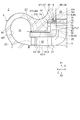
- FIG. 3 is a schematic cross-sectional view of the seal structure according to the first embodiment of the present invention.
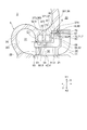
- FIG. 4 is a schematic cross-sectional view of the seal structure according to the second embodiment of the present invention, and is a schematic cross-sectional view for explaining a first plate member that comes into contact with the second inner wall surface.
- FIG. 5 is a schematic cross-sectional view of the seal structure according to the third embodiment of the present invention, and is a schematic cross-sectional view for explaining the second plate member.
- FIG. 6 is a schematic cross-sectional view of a seal structure according to a fourth embodiment of the present invention, and is a schematic cross-sectional view for explaining a first plate member including an axial plate portion.
- FIG. 7 is a schematic cross-sectional view of the seal structure according to the fifth embodiment of the present invention, and is a schematic cross-sectional view for explaining the third plate member.
- the seal structure 1 of the turbocharger 10 is supported by the above-mentioned turbine housing 3 having a scroll flow path 31 and the inside of the above-mentioned turbine housing 3.
- the above-mentioned nozzle plate 5 that defines the nozzle mount 4 and the exhaust gas flow path 32 between the nozzle mount 4, and the above-mentioned nozzle plate 5 including the above-mentioned annular plate portion 51 and the above-mentioned tubular portion 52.
- a sealing device 6 for sealing between the end surface 57 of the tubular portion 52 and the first inner wall surface 371 is provided.
- the exhaust gas flowing through the scroll flow path 31 does not pass through the exhaust gas flow path 32 and the turbine wheel 11 (wheel accommodating chamber 34), but the turbine housing 3 and the nozzle plate. It is a device for suppressing the outflow to the exhaust gas discharge flow path 33 through the gap C1 formed between the five and the exhaust gas discharge flow path 33.
- the above-described sealing device 6 includes a first plate member 7 having a single surface 72 that abuts on the end surface 57 of the tubular portion 52, and a first plate member 7, as shown in FIGS. 3 to 7.
- a sealing member 8 for sealing between the other surface 73 and the first inner wall surface 371 is included.
- the seal member 8 is configured to urge the first plate member 7 toward the end surface 57 of the tubular portion 52.
- the first plate member 7 is formed in an annular shape, for example, as shown in FIG.
- the outer diameter of the first plate member 7 is larger than the outer peripheral surface 58 of the tubular portion 52, and the inner diameter is larger than the inner peripheral surface 56 of the tubular portion 52.
- the first plate member 7 may be formed in an arc shape extending along the circumferential direction, or may be formed in a spiral shape wound around one or more turns along the circumferential direction. You may be.
- the first plate member 7 may be configured such that the outer diameter is the same as the outer peripheral surface 58 of the tubular portion 52 or smaller than the outer peripheral surface 58, and the inner diameter is the same as the inner peripheral surface 56 of the tubular portion 52. It may be the same or smaller than the inner peripheral surface 56.
- the seal member 8 is configured such that, for example, as shown in FIG. 3, the seal member 8 is formed in an annular shape and elastically deforms when compressed along the axial direction X. Has been done.
- the seal member 8 is arranged at the axial X position corresponding to the end surface 57 of the tubular portion 52 in a compressed state along the axial direction X. That is, the seal member 8 is located between the end surface 57 of the tubular portion 52 and the portion of the first inner wall surface 371 facing the end surface 57.
- the seal member 8 (8A) is formed in a V shape having an opening 81 on the outer side in the radial direction Y in its cross-sectional shape, for example, as shown in FIG.
- the seal member 8 may be formed in a U-shape or a J-shape (see FIGS. 8 to 13 described later) having an opening 81 on the outer side in the radial direction of the seal member 8. ..
- the gap C1 of the turbine housing 3 is defined. Since the amount of heat energy received from the exhaust gas is larger than that of the portion having the first inner wall surface 371, the amount of thermal deformation is also large. Therefore, when the turbocharger 10 is operated, the relative positional relationship between the first inner wall surface 371 of the turbine housing 3 and the end surface 57 of the tubular portion 52 of the nozzle plate 5 changes.
- the first plate member 7 is urged by the seal member 8 toward the end surface 57 of the tubular portion 52 of the nozzle plate 5, so that the first plate member 7 is between the seal member 8 and the nozzle plate 5. Since it is supported, one surface 72 of the first plate member 7 is swingable with respect to the end surface 57 of the tubular portion 52.
- the seal structure 1 slides the nozzle plate 5 with respect to the first plate member 7 when it receives the heat of the exhaust gas, so that the first inner wall surface 371 of the turbine housing 3 and the other surface 73 of the first plate member 7 are slid. It is possible to suppress changes in the relative positional relationship between and.
- the first inner wall surface 371 of the turbine housing 3 By suppressing the change in the relative positional relationship between the first inner wall surface 371 of the turbine housing 3 and the other surface 73 of the first plate member 7, the first inner wall surface 371 and the first plate member of the turbine housing 3 are suppressed. Deformation and wear of the sealing member 8 that seals between the other surface 73 of 7 can be suppressed.
- the first plate member 7 blocks (heat shields) the exhaust gas flowing from the scroll flow path 31 and the heat from the nozzle plate 5 so as not to be transmitted to the seal member 8, so that the seal member 8 is thermally expanded. And heat shrinkage can be suppressed, and eventually, deterioration of the sealing performance due to fatigue of the sealing member 8 can be suppressed. Therefore, according to the seal structure 1, stable sealing performance can be exhibited for a long period of time.
- the first plate member 7 described above has a coefficient of linear expansion equivalent to that of the turbine housing 3 described above (specifically, the difference in the coefficient of linear expansion between the turbine housing 3 and the first plate member 7 is ⁇ . It is made of a material that has (within 10%). In this case, since the amount of thermal deformation between the first plate member 7 and the first inner wall surface 371 can be made uniform, between the first inner wall surface 371 of the turbine housing 3 and the other surface 73 of the first plate member 7. It is possible to effectively suppress changes in the relative positional relationship of.
- the first plate member 7 described above includes a radial plate portion 71 extending towards the second inner wall surface 372 of the turbine housing 3, as shown in FIGS. 4-7.
- the outer end surface 74 of the radial plate portion 71 is configured to come into contact with the second inner wall surface 372.
- the radial plate portion 71 has the above-mentioned other surface 73 on one side (one side X1) in the thickness direction, and the above-mentioned one surface on the other side (the other side X2) in the thickness direction.
- the seal structure 1 aligns the amount of thermal deformation of the turbine housing 3 and the first plate member 7 in the radial direction, so that the first inner wall surface 371 and the first plate member 7 of the turbine housing 3 receive the heat of the exhaust gas.
- the change in the relative positional relationship with the other surface 73 can be suppressed more effectively, and the deformation and wear of the seal member 8 can be suppressed more effectively.
- the outer end surface 74 of the radial plate portion 71 is in contact with the second inner wall surface 372 of the turbine housing 3, the exhaust gas that does not pass through the turbine wheel 11 comes into contact with the seal member 8. Therefore, it is possible to more effectively suppress the thermal expansion and contraction of the seal member 8.
- the seal member 8 described above is configured to abut the first inner wall surface 371.
- the end portion 82 of one side X1 of the open end portions 82, 83 abuts on the first inner wall surface 371, and the end portion 83 of the other side X2. Is in contact with the other surface 73 of the first plate member 7.
- the seal member 8 urges the first plate member 7 toward the end surface 57 of the tubular portion 52 and the first inner wall surface 371 toward one side X1 by an elastic force (restoring force). There is.
- the seal member 8 is configured to be in contact with the first inner wall surface 371 to seal between the other surface 73 of the first plate member 7 and the first inner wall surface 371. Can be done.
- the above-mentioned sealing device 6 further includes a second plate member 61 having one surface 611 in contact with the first inner wall surface 371, and the sealing member 8 is a second. It is configured to come into contact with the other surface 612 of the plate member 61.
- the second plate member 61 is formed in an annular shape as shown in FIG.
- the outer diameter of the second plate member 61 is larger than the outer peripheral surface 58 of the tubular portion 52, and the inner diameter is larger than the inner peripheral surface 56 of the tubular portion 52.
- the outer end surface 613 of the second plate member 61 is configured to come into contact with the second inner wall surface 372.
- the second plate member 61 may be formed in an arc shape extending along the circumferential direction, or may be formed in a spiral shape wound around one or more turns along the circumferential direction. You may be.
- the second plate member 61 may be configured such that the outer diameter is the same as the outer peripheral surface 58 of the tubular portion 52 or smaller than the outer peripheral surface 58, and the inner diameter is the same as the inner peripheral surface 56 of the tubular portion 52. It may be the same or smaller than the inner peripheral surface 56. Further, the outer end surface 613 of the second plate member 61 may have a gap between it and the second inner wall surface 372.
- the sealing member 8 urges the first plate member 7 toward the end surface 57 of the tubular portion 52 by an elastic force (restoring force), and brings the second plate member 61 and the first inner wall surface 371 to one side X1. I'm urging towards.
- the seal member 8 is configured to abut on the other surface 612 of the second plate member 61 having one surface 611 that abuts on the first inner wall surface 371, the turbine is provided by the second plate member 61.
- the heat from the housing 3 can be blocked (heat shielded).
- the above-mentioned second plate member 61 has a coefficient of linear expansion equivalent to that of the above-mentioned first plate member 7 (specifically, the coefficient of linear expansion of the first plate member 7 and the second plate member 61). The difference is within ⁇ 10%). In this case, since the amount of thermal deformation between the first plate member 7 and the second plate member 61 can be made uniform, between the other surface 73 of the first plate member 7 and the other surface 612 of the second plate member 61. It is possible to effectively suppress changes in the relative positional relationship of.
- the above-mentioned first plate member 7 has a radial direction with the above-mentioned radial plate portion 71 extending toward the second inner wall surface 372 of the turbine housing 3. Includes an axial plate portion 76 extending from the inner end portion 75 of the plate portion 71 toward the first inner wall surface 371 side.
- the first plate member 7 since the first plate member 7 includes the axial plate portion 76 extending from the inner end portion 75 of the radial plate portion 71 toward the first inner wall surface 371 side, the axial plate portion By narrowing the gap between the first plate member 7 and the turbine housing 3 by 76, it is possible to prevent the exhaust gas that has passed through the turbine wheel 11 from flowing toward the seal member 8 through the gap. By suppressing the exhaust gas that has passed through the turbine wheel 11 from coming into contact with the seal member 8, the thermal expansion and contraction of the seal member 8 can be suppressed more effectively.
- the first inner wall surface 371 and the bore inner wall surface 361 extend along a direction intersecting the first inner wall surface 371 and the bore inner wall surface 361.
- a cutout surface 374 is formed.
- the first inner wall surface 371 is connected to the bore inner wall surface 361 via the notch surface 374.
- the axial plate portion 76 extends along the axial direction X to the space notched by the notched surface 374.
- the downstream end 761 of the axial plate portion 76 is located on one side X1 in the axial direction X with respect to the first inner wall surface 371, and a part of the downstream end 761 faces the cutout surface 374. In the illustrated embodiment, the downstream end 761 does not abut on the notch surface 374 and has a gap between it and the notch surface 374.
- the first plate member 7 since the axial plate portion 76 extends to the space cut out by the cutout surface 374, the first plate member 7 and the turbine are formed by the axial plate portion 76.
- the gap with the housing 3 can be further narrowed. According to such a first plate member 7, it is possible to effectively suppress the exhaust gas that has passed through the turbine wheel 11 from flowing toward the seal member 8 through the gap.
- the seal device 6 described above is a third plate member 62 attached to the outer peripheral surface 58 of the tubular portion 52 and is a second inner wall surface of the turbine housing 3.
- a third plate member 62 extending towards 372 is further included.
- the third plate member 62 fits the inner end portion 621 into the outer peripheral groove portion 581 formed on the outer peripheral surface 58 of the tubular portion 52 along the circumferential direction. Therefore, it is supported by the nozzle plate 5.
- the third plate member 62 is configured to be removable from the outer peripheral groove portion 581.
- the third plate member 62 comprises a plate-like member formed in an arc shape extending along the circumferential direction. Further, in some embodiments, the third plate member 62 comprises a spirally formed seal ring wound around one or more turns along the circumferential direction.
- the sealing device 6 since the sealing device 6 includes the third plate member 62 extending toward the second inner wall surface 372 of the turbine housing 3, the third plate member 62 makes the nozzle plate 5 and the turbine housing 3 By narrowing the gap with the second inner wall surface 372, the flow rate of the exhaust gas flowing through the gap toward the seal member 8 can be suppressed. By suppressing the flow rate of the exhaust gas flowing toward the seal member 8, the amount of heat energy applied to the seal member 8 from the exhaust gas can be reduced, and the thermal expansion and contraction of the seal member 8 can be suppressed. ..
- the cross-sectional shape of the seal member 8 described above is formed into a U-shape, a V-shape, or a J-shape having an opening 81 on the outer side in the radial direction Y.
- the cross-sectional shape of the seal member 8 is formed into a U-shape, a V-shape, or a J-shape having an opening 81 on the outer side in the radial direction, and thus the other surfaces 73 and the first of the first plate member 7.
- the opening 81 of the sealing member 8 faces the scroll flow path 31 side. Therefore, since the opening 81 of the sealing member 8 is expanded by the pressure of the exhaust gas in the scroll flow path 31, the sealing member 8 effectively seals between the end surface 57 of the tubular portion 52 and the first inner wall surface 371. Can be done.
- the cross-sectional shape of the seal member 8 (8B) described above is formed in a J shape having an opening 81 on the outer side in the radial direction Y.
- the seal member 8 (8B) is configured such that the end 82 of one side X1 of the open ends 82, 83 is longer than the end 83 of the other side X2.
- the outer end of the end 82 is located radially Y outside of the outer end of the end 83.
- the second end portion 82 having a longer length is compared with the case where the seal member 8 (8B) is formed in a U shape or a V shape. Since the contact area with 1 inner wall surface 371 can be increased, elastic force (restoring force) can be stably generated for a long period of time.
- FIG. 8 is a schematic cross-sectional view of the seal structure according to the sixth embodiment of the present invention.
- FIG. 9 is a schematic cross-sectional view of a first modification of the seal structure according to the sixth embodiment.
- FIG. 10 is a schematic cross-sectional view of a second modification of the seal structure according to the sixth embodiment.
- FIG. 11 is a schematic cross-sectional view of a third modification of the seal structure according to the sixth embodiment.
- the above-mentioned turbine housing 3 includes the above-mentioned second inner wall surface 372 and the above-mentioned third inner wall surface 373. Circumferential direction on at least one of the second inner wall surface 372 and the third inner wall surface 373 of the turbine housing 3, the outer peripheral surface 58 of the tubular portion 52 of the nozzle plate 5 and the back surface 54 of the annular plate portion 51 described above. At least one groove 9 extending along the line was formed.
- At least one groove portion 9 has a rectangular cross-sectional shape in a cross section along the axis LA. Further, at least one groove 9 is formed in an annular shape. In another embodiment, at least one groove 9 may be formed in a cross-sectional shape other than a rectangular shape, or may be formed in an arc shape.
- the above-mentioned at least one groove portion 9 includes one third inner wall surface side groove portion 91 formed on the above-mentioned third inner wall surface 373.
- at least one groove portion 9 described above includes a plurality of third inner wall surface side groove portions 92 provided on the third inner wall surface 373 described above at intervals in the radial direction Y.
- the third inner wall surface side groove portion 91 described above can have a larger cross-sectional area in the cross section than the third inner wall surface side groove portion 92.
- At least one groove portion 9 described above is a plurality of back surface side groove portions 93 provided on the back surface 54 of the annular plate portion 51 at intervals in the radial direction, and a tubular portion 52.
- at least one groove portion 9 described above includes the plurality of third inner wall surface side groove portions 92 described above and the plurality of back surface side groove portions 93 described above.
- At least one of the second inner wall surface 372 and the third inner wall surface 373 of the turbine housing 3, the outer peripheral surface 58 of the tubular portion 52 of the nozzle plate 5, and the back surface 54 of the annular plate portion 51 is formed.
- the exhaust gas flowing from the scroll flow path 31 toward the seal member 8 is expanded in at least one groove 9 (expansion chamber).
- the flow rate of the exhaust gas flowing toward the seal member 8 can be suppressed.
- the amount of heat energy applied to the seal member 8 from the exhaust gas can be reduced, and the thermal expansion and contraction of the seal member 8 can be suppressed. ..
- At least one groove portion 9 in this embodiment is combined with the above-mentioned seal structure 1 in the illustrated embodiment, it can be implemented independently.
- at least one groove portion 9 in the present embodiment does not have the above-mentioned sealing device 6 for sealing between the end surface 57 of the tubular portion 52 and the first inner wall surface 371 (seal structure 1 to sealing device 6). (Excluded structure) and a seal structure that seals between the end surface 57 of the tubular portion 52 and the first inner wall surface 371 only by the seal member 8 (a structure in which the seal device 6 other than the seal member 8 is excluded from the seal structure 1). It is applicable to such as.
- FIG. 12 is a schematic cross-sectional view of the seal structure according to the seventh embodiment of the present invention.
- FIG. 13 is a schematic cross-sectional view of the seal structure according to the eighth embodiment of the present invention.
- the turbine housing 3 described above includes the third inner wall surface 373 described above, and at least one groove 9 described above is formed on the third inner wall surface 373.
- the third inner wall surface side groove portion 92 described above is included.
- the nozzle plate 5 described above includes at least one nozzle plate side projecting portion 59 projecting from the back surface 54 into the inside of the third inner wall surface side groove portion 92.
- the nozzle plate side protruding portion 59 has a rectangular cross-sectional shape in a cross section along the axis LA. Further, the nozzle plate side protruding portion 59 is formed in an annular shape. In another embodiment, the nozzle plate side protrusion 59 may be formed in a cross-sectional shape other than a rectangular shape, or may be formed in an arc shape extending along the circumferential direction.
- At least one third inner wall surface side groove portion 92 described above includes a plurality of third inner wall surface side groove portions 92 provided on the third inner wall surface 373 at intervals in the radial direction Y.
- the at least one nozzle plate side projecting portion 59 described above includes a plurality of nozzle plate side projecting portions 59 projecting from portions on the back surface 54 that are spaced apart from each other in the radial direction Y.
- the number of nozzle plate-side projecting portions 59 projecting inside the third inner wall surface-side groove portion 92 increases, the total length of the gap C1 between the turbine housing 3 and the nozzle plate 5 can be lengthened, and the gap C1 flows through the gap C1. Since the number of times the exhaust gas flow direction is changed in the intersecting (orthogonal) direction can be increased, the flow rate of the exhaust gas flowing toward the seal member 8 can be suppressed.
- the nozzle plate 5 since the nozzle plate 5 includes the nozzle plate side projecting portion 59 projecting from the back surface 54 to the inside of the third inner wall surface side groove portion 92, the nozzle projecting to the inside of the third inner wall surface side groove portion 92.
- the plate-side protrusion 59 By increasing the total length of the gap C1 between the turbine housing 3 and the nozzle plate 5 by the plate-side protrusion 59, the flow rate of the exhaust gas flowing toward the seal member 8 can be suppressed.
- the amount of heat energy applied to the seal member 8 from the exhaust gas can be reduced, and the thermal expansion and contraction of the seal member 8 can be suppressed. ..
- the nozzle plate side protrusion 59 in this embodiment is combined with the seal structure 1 described above in the illustrated embodiment, it can be implemented independently.
- the nozzle plate side protrusion 59 in the present embodiment can be applied to the above-mentioned structure in which the sealing device 6 is removed from the sealing structure 1, the structure in which the sealing device 6 other than the sealing member 8 is removed from the sealing structure 1, and the like. Is.
- the turbine housing 3 described above includes the third inner wall surface 373 described above, and at least one groove portion 9 described above is formed on the back surface 54 of the annular plate portion 51. Includes at least one of the above-mentioned back side gutters 93.
- the turbine housing 3 described above includes at least one housing-side projecting portion 38 projecting from the third inner wall surface 373 into the back surface side groove portion 93.
- the housing-side protrusion 38 has a rectangular cross-sectional shape in a cross section along the axis LA. Further, the housing-side protrusion 38 is formed in an annular shape. In another embodiment, the housing-side protrusion 38 may be formed in a cross-sectional shape other than a rectangular shape, or may be formed in an arc shape extending along the circumferential direction.
- the at least one back surface gutter 93 described above includes a plurality of back surface gutters 93 provided on the back surface 54 at intervals in the radial direction Y, and at least one housing side protrusion described above.
- the portion 38 includes a plurality of housing-side projecting portions 38 projecting from portions on the third inner wall surface 373 that are spaced apart from each other in the radial direction Y.
- the number of housing-side protruding portions 38 protruding into the rear-side groove portion 93 increases, the total length of the gap C1 between the turbine housing 3 and the nozzle plate 5 can be lengthened, and the flow direction of the exhaust gas flowing through the gap C1. Since the number of times of changing in the direction of crossing (orthogonal) can be increased, the flow rate of the exhaust gas flowing toward the seal member 8 can be suppressed.
- the turbine housing 3 since the turbine housing 3 includes a housing-side projecting portion 38 projecting from the third inner wall surface 373 to the inside of the back-side gutter portion 93, the housing-side projecting portion 38 projecting inside the back-side gutter portion 93. Therefore, by increasing the total length of the gap C1 between the turbine housing 3 and the nozzle plate 5, the flow rate of the exhaust gas flowing toward the seal member 8 can be suppressed. By suppressing the flow rate of the exhaust gas flowing toward the seal member 8, the amount of heat energy applied to the seal member 8 from the exhaust gas can be reduced, and the thermal expansion and contraction of the seal member 8 can be suppressed. ..
- the housing-side protrusion 38 in the present embodiment is combined with the above-mentioned seal structure 1 in the illustrated embodiment, but can be implemented independently.
- the housing-side protruding portion 38 in the present embodiment can be applied to a structure in which the sealing device 6 is removed from the above-mentioned sealing structure 1, a structure in which the sealing device 6 other than the sealing member 8 is removed from the sealing structure 1, and the like. is there.
- the turbocharger 10 includes the above-mentioned turbine wheel 11 and the above-mentioned seal structure 1.
- the seal structure 1 of the turbocharger 10 can exhibit stable sealing performance for a long period of time, deterioration of the performance of the turbocharger 10 can be suppressed for a long period of time.
- the present invention is not limited to the above-described embodiment, and includes a modified form of the above-described embodiment and a combination of these embodiments as appropriate.
Landscapes
- Engineering & Computer Science (AREA)
- Mechanical Engineering (AREA)
- General Engineering & Computer Science (AREA)
- Chemical & Material Sciences (AREA)
- Combustion & Propulsion (AREA)
- Supercharger (AREA)
- Gasket Seals (AREA)
- Turbine Rotor Nozzle Sealing (AREA)
Priority Applications (5)
| Application Number | Priority Date | Filing Date | Title |
|---|---|---|---|
| CN201980095923.0A CN113906203B (zh) | 2019-05-31 | 2019-05-31 | 涡轮增压器的密封构造以及涡轮增压器 |
| DE112019007207.2T DE112019007207T5 (de) | 2019-05-31 | 2019-05-31 | Abdichtungsstruktur eines Turboladers und Turbolader |
| US17/606,563 US11828222B2 (en) | 2019-05-31 | 2019-05-31 | Sealing structure of turbocharger and turbocharger |
| PCT/JP2019/021668 WO2020240805A1 (ja) | 2019-05-31 | 2019-05-31 | ターボチャージャのシール構造およびターボチャージャ |
| JP2021521717A JP7240490B2 (ja) | 2019-05-31 | 2019-05-31 | ターボチャージャのシール構造およびターボチャージャ |
Applications Claiming Priority (1)
| Application Number | Priority Date | Filing Date | Title |
|---|---|---|---|
| PCT/JP2019/021668 WO2020240805A1 (ja) | 2019-05-31 | 2019-05-31 | ターボチャージャのシール構造およびターボチャージャ |
Publications (1)
| Publication Number | Publication Date |
|---|---|
| WO2020240805A1 true WO2020240805A1 (ja) | 2020-12-03 |
Family
ID=73553721
Family Applications (1)
| Application Number | Title | Priority Date | Filing Date |
|---|---|---|---|
| PCT/JP2019/021668 Ceased WO2020240805A1 (ja) | 2019-05-31 | 2019-05-31 | ターボチャージャのシール構造およびターボチャージャ |
Country Status (5)
| Country | Link |
|---|---|
| US (1) | US11828222B2 (https=) |
| JP (1) | JP7240490B2 (https=) |
| CN (1) | CN113906203B (https=) |
| DE (1) | DE112019007207T5 (https=) |
| WO (1) | WO2020240805A1 (https=) |
Families Citing this family (4)
| Publication number | Priority date | Publication date | Assignee | Title |
|---|---|---|---|---|
| GB201912322D0 (en) * | 2019-08-28 | 2019-10-09 | Rolls Royce Plc | Gas turbine engine flow control |
| US12553355B2 (en) * | 2022-03-22 | 2026-02-17 | Accelleron Switzerland Ltd. | Nozzle ring for a radial turbine, exhaust turbine, and turbocharger |
| WO2023228467A1 (ja) * | 2022-05-25 | 2023-11-30 | 株式会社Ihi | タービンおよび過給機 |
| CN117189342B (zh) * | 2023-10-27 | 2026-04-21 | 潍坊富源增压器有限公司 | 一种涡轮端密封结构 |
Citations (2)
| Publication number | Priority date | Publication date | Assignee | Title |
|---|---|---|---|---|
| JPS62108501U (https=) * | 1985-12-25 | 1987-07-10 | ||
| JP2006125588A (ja) * | 2004-11-01 | 2006-05-18 | Ishikawajima Harima Heavy Ind Co Ltd | 過給機および密封装置 |
Family Cites Families (11)
| Publication number | Priority date | Publication date | Assignee | Title |
|---|---|---|---|---|
| JPS62108501A (ja) * | 1985-11-06 | 1987-05-19 | 株式会社東芝 | 抵抗器 |
| DE102007049925B4 (de) | 2007-10-18 | 2012-10-31 | Federal-Mogul Sealing Systems Gmbh | Geschweißte Metalldichtung |
| JP5402061B2 (ja) * | 2009-02-17 | 2014-01-29 | 株式会社Ihi | ターボチャージャ |
| JP5402682B2 (ja) | 2010-01-29 | 2014-01-29 | 株式会社Ihi | ターボチャージャのシール装置 |
| JP5561368B2 (ja) | 2010-09-13 | 2014-07-30 | 株式会社Ihi | 固定翼式ターボチャージャ |
| US8763393B2 (en) * | 2011-08-08 | 2014-07-01 | Honeywell International Inc. | Sealing arrangement between a variable-nozzle assembly and a turbine housing of a turbocharger |
| JP5118767B1 (ja) | 2011-09-22 | 2013-01-16 | 三菱重工業株式会社 | ターボチャージャのシールリング組付け方法及びターボチャージャ |
| DE102012006711A1 (de) | 2012-01-18 | 2013-07-18 | Ihi Charging Systems International Gmbh | Abgasturbolader |
| JP5949164B2 (ja) | 2012-05-29 | 2016-07-06 | 株式会社Ihi | 可変ノズルユニット及び可変容量型過給機 |
| EP2685054B1 (de) | 2012-07-09 | 2020-11-25 | ABB Schweiz AG | Diffusor einer abgasturbine |
| US9556880B2 (en) * | 2013-06-26 | 2017-01-31 | Honeywell International Inc. | Turbine exhaust seal |
-
2019
- 2019-05-31 CN CN201980095923.0A patent/CN113906203B/zh active Active
- 2019-05-31 DE DE112019007207.2T patent/DE112019007207T5/de active Pending
- 2019-05-31 US US17/606,563 patent/US11828222B2/en active Active
- 2019-05-31 JP JP2021521717A patent/JP7240490B2/ja active Active
- 2019-05-31 WO PCT/JP2019/021668 patent/WO2020240805A1/ja not_active Ceased
Patent Citations (2)
| Publication number | Priority date | Publication date | Assignee | Title |
|---|---|---|---|---|
| JPS62108501U (https=) * | 1985-12-25 | 1987-07-10 | ||
| JP2006125588A (ja) * | 2004-11-01 | 2006-05-18 | Ishikawajima Harima Heavy Ind Co Ltd | 過給機および密封装置 |
Also Published As
| Publication number | Publication date |
|---|---|
| CN113906203A (zh) | 2022-01-07 |
| US11828222B2 (en) | 2023-11-28 |
| JP7240490B2 (ja) | 2023-03-15 |
| JPWO2020240805A1 (https=) | 2020-12-03 |
| DE112019007207T5 (de) | 2022-01-13 |
| US20220205382A1 (en) | 2022-06-30 |
| CN113906203B (zh) | 2023-10-31 |
Similar Documents
| Publication | Publication Date | Title |
|---|---|---|
| US8616007B2 (en) | Structural attachment system for transition duct outlet | |
| WO2020240805A1 (ja) | ターボチャージャのシール構造およびターボチャージャ | |
| US8657573B2 (en) | Circumferential sealing arrangement | |
| JP2009047043A (ja) | 軸流タービン | |
| US10472982B2 (en) | Variable geometry turbine assembly | |
| JP6177421B2 (ja) | シール構造及び該シール構造を備える過給機 | |
| EP2912279A1 (en) | Gas turbine including belly band seal anti-rotation device | |
| US6644668B1 (en) | Brush seal support | |
| JP5374563B2 (ja) | 軸流タービン | |
| JP2012087928A (ja) | ターボ機械シール組立体 | |
| EP2914814A1 (en) | Belly band seal with underlapping ends | |
| US11371369B2 (en) | Vanes and shrouds for a turbo-machine | |
| CN114526264A (zh) | 具有衬套环和偏置构件的可变导向叶片组件 | |
| JP4815536B2 (ja) | ガスタービンエンジンのシール構造 | |
| EP3542031B1 (en) | Vane arrangement for a turbo-machine | |
| US10830083B2 (en) | Gas turbine engine with a turbine blade tip clearance control system | |
| KR20160030082A (ko) | 가변 구조 터빈 | |
| US10294814B2 (en) | Ellipsoidal inner central blade storage space | |
| US11459902B1 (en) | Seal for a wave rotor disk engine | |
| US20140054863A1 (en) | Seal assembly for a turbine system |
Legal Events
| Date | Code | Title | Description |
|---|---|---|---|
| 121 | Ep: the epo has been informed by wipo that ep was designated in this application |
Ref document number: 19930517 Country of ref document: EP Kind code of ref document: A1 |
|
| ENP | Entry into the national phase |
Ref document number: 2021521717 Country of ref document: JP Kind code of ref document: A |
|
| 122 | Ep: pct application non-entry in european phase |
Ref document number: 19930517 Country of ref document: EP Kind code of ref document: A1 |