WO2020235481A1 - 輸送容器及び収容方法 - Google Patents
輸送容器及び収容方法 Download PDFInfo
- Publication number
- WO2020235481A1 WO2020235481A1 PCT/JP2020/019447 JP2020019447W WO2020235481A1 WO 2020235481 A1 WO2020235481 A1 WO 2020235481A1 JP 2020019447 W JP2020019447 W JP 2020019447W WO 2020235481 A1 WO2020235481 A1 WO 2020235481A1
- Authority
- WO
- WIPO (PCT)
- Prior art keywords
- transport container
- cold storage
- main body
- lid
- cold
- Prior art date
- Legal status (The legal status is an assumption and is not a legal conclusion. Google has not performed a legal analysis and makes no representation as to the accuracy of the status listed.)
- Ceased
Links
Images









Classifications
-
- B—PERFORMING OPERATIONS; TRANSPORTING
- B65—CONVEYING; PACKING; STORING; HANDLING THIN OR FILAMENTARY MATERIAL
- B65D—CONTAINERS FOR STORAGE OR TRANSPORT OF ARTICLES OR MATERIALS, e.g. BAGS, BARRELS, BOTTLES, BOXES, CANS, CARTONS, CRATES, DRUMS, JARS, TANKS, HOPPERS, FORWARDING CONTAINERS; ACCESSORIES, CLOSURES, OR FITTINGS THEREFOR; PACKAGING ELEMENTS; PACKAGES
- B65D81/00—Containers, packaging elements, or packages, for contents presenting particular transport or storage problems, or adapted to be used for non-packaging purposes after removal of contents
- B65D81/18—Containers, packaging elements, or packages, for contents presenting particular transport or storage problems, or adapted to be used for non-packaging purposes after removal of contents providing specific environment for contents, e.g. temperature above or below ambient
Definitions
- the present invention relates to a transport container and a storage method.
- the present application claims priority based on Japanese Patent Application No. 2019-0945664 filed in Japan on May 20, 2019, the contents of which are incorporated herein by reference.
- a heat-insulating packaging container 2 that seals and houses a transportation object 8 that is entirely wrapped by a heat-retaining sheet 4 after filling a space with a heat-insulating member 3 or the like is a constant-temperature transportation packing device 1. It is disclosed as.
- the heat insulating sheet 4 includes a bag-shaped portion 4a1 in which a temperature adjusting material 5 that changes state from a liquid to a solid when the temperature drops below a certain temperature is sealed.
- the object to be transported (hereinafter, this may be referred to as an object) is entirely wrapped with a heat insulating sheet 4 containing a cold storage material or the like, but the heat insulating sheet 4 is stopped with a tape or the like. Due to the structure, the heat insulating sheet 4 and the object to be transported 8 may not be sufficiently adhered to each other.
- one aspect of the present invention provides a transport container capable of bringing the cold storage material and the object into closer contact with each other.
- the transport container of one aspect of the present invention is a transport container including a main body portion having a bottom surface portion and a side surface portion, and a lid portion provided so as to open and close the opening of the main body portion.
- the main body and the lid have elasticity and the object is surrounded by at least one cold storage device in which a plurality of cold storage parts for holding the cold storage material are connected to each other.
- the volume of the shipping container is larger than the volume before storage.
- the cold storage material holding the cold storage material does not shift, and there is no place where the cold storage material does not come into contact with the object.
- the cold insulator suppresses the heat inflow between the outside and the object, and the temperature of the object can be strictly maintained at the phase transition temperature of the cold storage material.
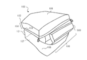
- FIG. 1A is a perspective view seen from the front when the transport container according to the first embodiment is closed.
- FIG. 1B is a perspective view seen from the back surface when the transport container according to the first embodiment is closed.
- FIG. 1C is a schematic view when the transport container according to the first embodiment is opened.
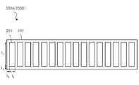
- FIG. 2 is a schematic view of a cold insulation device used in one aspect of the present invention.
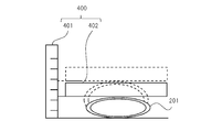
- FIG. 3 is a schematic view showing the relationship between the pressing pressure of the cold storage portion and the displacement of the height of the cold storage portion with respect to the pressing pressure. It is the schematic of the measuring apparatus which measures the pushing pressure of a cold storage part and the relationship of the displacement of the height of a cold storage part with respect to a pushing pressure.
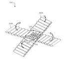
- FIG. 5A is a schematic view of an object and a cold insulator to be housed in a transport container according to the first embodiment.
- FIG. 5B is a schematic view of the contents according to the first embodiment.
- FIG. 6A is a schematic view of accommodating the object in the transport container according to the first embodiment.
- FIG. 6B is a schematic view when the object is housed in the transport container according to the first embodiment.
- FIG. 7 is a temperature characteristic diagram showing a temperature change with time between Example 1 and Comparative Example 1 of the transport container according to the first embodiment.
- FIG. 8 is a schematic view of a transport container according to Comparative Example 2.
- FIG. 9 is a temperature characteristic diagram showing a temperature change with time between Example 1 and Comparative Example 2 of the transport container according to the first embodiment.
- FIG. 10A is a schematic view when the object is stored in the transport container according to the second embodiment.
- FIG. 10B is a schematic view when the object is housed in the transport container according to the second embodiment.
- FIG. 11 is a temperature characteristic diagram showing a temperature change with time between the first embodiment and the second embodiment of the transport container according to the first embodiment.
- FIG. 12A is a perspective view seen from the front when another shipping container according to the first embodiment is closed.
- FIG. 12B is a perspective view seen from the back surface when another shipping container according to the first embodiment is closed.
- FIG. 12C is a schematic view when another shipping container according to the first embodiment is opened.
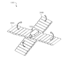
- FIG. 13A is a schematic view of an object and a cold storage device to be housed in a transport container according to the second embodiment.
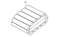
- FIG. 13B is a schematic view of the contents according to the second embodiment.
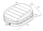
- FIG. 14 is a schematic view when the object is housed in the transport container according to the second embodiment.
- FIG. 1A, 1B, and 1C show the transport container 100 according to the present embodiment.
- FIG. 1A is a perspective view seen from the front when the transport container 100 according to the present embodiment is closed.
- FIG. 1B is a perspective view seen from the back surface when the transport container 100 according to the present embodiment is closed.
- FIG. 1C is a schematic view when the transport container 100 according to the present embodiment is opened.
- the transport container 100 has a bottom surface portion 107 and a side surface portion 108, and has an elastic main body portion 101 and an opening 106 of the main body portion 101 that can be opened and closed.
- a lid portion 102 having elasticity is provided.
- the main body 101 and the lid 102 may have a heat insulating property, which suppresses the inflow of heat from the outside of the transport container 100 and prolongs the phase transition time of the cold storage material described later. It is possible to extend the cold insulation time of the object 501.
- the transport container 100 includes a connecting portion 105 for connecting the main body portion 101 and the lid portion 102, and a fixing portion 103 for fixing the lid portion 102 to the main body portion 101 and the opening 106 so as to be openable and closable.
- the fixing portion 103 is, for example, a fastener, and is a line fastener as shown in FIGS. 1A, 1B, and 1C.
- the fixing portion 103 may be a hook-and-loop fastener or a point fastener.
- the lid portion 102 has a plate-shaped upper surface portion 109 corresponding to the opening 106, and an extension extending from the upper surface portion 109 toward the side surface portion 108 of the main body portion 101 in a state where the opening portion 106 is narrowed by the lid portion 102.
- a unit 104 is provided.
- the bottom surface portion 107 includes a bottom plate portion 110 having a lower elasticity than the main body portion 101. Since the main body 101 is provided with the bottom plate 110, even if the transport container 100 is highly elastic and easily changes in shape, the shape is stable and self-supporting, and the transport container 100 can be accommodated when the container 300 is stored. It becomes unnecessary to support the container 300, which will be described later, and can be easily stored in the transport container 100. Further, since the transport container 100 is provided with the bottom plate portion 110, the heat insulating property is improved as compared with the case where the bottom plate portion 110 is not provided.
- the bottom plate portion 110 is, for example, EVA resin or the like.
- the volume of the transport container 100 is the object 501 in a state of being surrounded by the cold insulators 200A and 200B shown in FIG. 2 in which a plurality of cold storage portions 201 each holding a cold storage material inside are connected (hereinafter, this is the container 500).
- the volume is larger than the volume of the transport container 100 before the storage.
- FIG. 2 shows a schematic view of the cold insulators 200A and 200B used in one aspect of the present invention.
- the cold insulators 200A and 200B each include a plurality of cold storage units 201 that hold the cold storage material inside.
- the material of the cold storage material held inside the cold storage unit 201 is, for example, a material that becomes solid at a constant temperature and changes its shape from solid to liquid when the temperature rises. Further, the cold storage portion 201 is connected by a seal portion 202 formed by thermocompression bonding the upper surface and the lower surface of the outer periphery of the cold storage portion 201. The seal portion is also formed on the outer periphery of the cold insulation tools 200A and 200B.
- the material forming the main body 101 and the lid 102 includes a rubber material such as chloroprene, the main body 101 and the lid 102 are elastically deformed, and the main body 101 and the lid 102 tighten the container 300.
- the transport container 100 As the Young's modulus of the material forming the main body 101 and the lid 102 is lower, the transport container 100 is elastically deformed and the transport container 100 is deformed even if the difference in volume between the transport container 100 and the container 300 is large. It becomes possible to accommodate the container 300.
- the upper limit of the Young's modulus of the material forming the main body 101 and the lid 102 is 100 MPa or less, preferably 10 MPa or less.
- the lower limit of the Young's modulus of the material forming the main body 101 and the lid 102 is the pressure at which the cold storage section 201 provided in the cold insulators 200A and 200B can be tightened so as not to separate from the object 501 when the cold storage section 201 is in a liquid state.
- Young's modulus defines the one-dimensional elastic modulus in the vertical direction of the material, and the degree of tightening when tightening the three-dimensional object 501 from all directions as in one aspect of the present invention is only Young's modulus. It is difficult to define with. Therefore, the pressure at which the main body 101 and the lid 102 tighten the object 501 and the cold insulators 200A and 200B is defined as shown in FIGS. 3 and 4 below.
- a pressing pressure which is a pressure for pressing the cool packs 200A and 200B, is used to determine the tightening pressure.
- FIG. 3 is a schematic view showing the relationship between the pressing pressure of the cold storage unit 201 provided in the cold storage tools 200A and 200B and the displacement of the height of the cold storage unit 201 with respect to the pressing pressure. Note that FIG. 3 is obtained by using a measuring device 400 for measuring the relationship of the height displacement of the cold storage unit 201 with respect to the pressing pressure shown in FIG.
- the measuring device 400 includes a displacement measuring unit 401 for measuring displacement and a rigid body 402 that does not deform when pressure is applied. Pressure is applied to the cold storage unit 201 via the rigid body 402, and the relationship between the applied pressure and the displacement of the height of the cold storage unit 201 from the time when no pressure is applied is measured.
- the cold storage section 201 is plastically deformed, and the height of the cold storage section 201 becomes smaller in proportion to the pressure applied to the cold storage section 201.
- the displacement of the height of the cold storage unit 201 is constant regardless of the pressure applied to the cold storage unit 201, and the shape of the cold storage unit 201 does not change with the pressure applied to the cold storage unit 201.
- the cold storage section 201 is broken and the cold storage material held inside the cold storage section 201 goes out of the cold storage section 201.
- the pressure for tightening the object 501 and the cold storage section 201 of the material forming the main body 101 and the lid 102 is a pressure P1 or higher that stops after the plastic deformation of the cold storage section 201 occurs when a pressing force is applied to the cold storage section 201. is there.
- the pressure P1 is the pressure at the boundary between the region 301 and the region 302.
- the pressure for tightening the object 501 and the cold storage portion 201 of the material forming the main body 101 and the lid 102 By setting the pressure for tightening the object 501 and the cold storage portion 201 of the material forming the main body 101 and the lid 102 to be pressure P1 or higher, the object 501 and the cold insulators 200A and 200B are brought into close contact with each other.
- the cold storage unit 201 follows the shape of the object 501 and changes its shape.
- the cold storage unit 201 When the cold storage material flows along with the phase transition from the solid to the liquid, the cold storage unit 201 follows the shape of the object 501 and changes its shape, so that the temperature of the object 501 is further changed in the phase of the cold storage material. Can be maintained at temperature. On the other hand, if the tightening pressure is equal to or higher than the pressure P2 and is as high as the region 303, the bag will break.
- the pressure for tightening the object 501 and the cold storage portion 201 of the material forming the main body 101 and the lid 102 is preferably in the pressure range of the region 302 in which the pressure P1 or more and the pressure P2 or less.
- FIG. 5A is a schematic view of the object 501 and the cold storage devices 200A and 200B housed in the transport container 100 according to the present embodiment.
- FIG. 5B is a schematic view of the contained object 300 according to the present embodiment.
- FIG. 6A is a schematic view when the object 501 is housed in the transport container 100 according to the present embodiment.
- FIG. 6B is a schematic view of the container 100 according to the present embodiment when the container 500 is stored.
- FIG. 5A the operator surrounds the object 501 with a cold insulator 200A including a plurality of cold storage portions 201 which are connected and hold the cold storage material inside, and then the object 501 and the cold storage material.
- the tool 200A is surrounded by the cold box 200B to make the container 500.
- FIG. 5B shows an outline of the contained object 500 in which the object 501 is contained.
- the object 501 is surrounded by the cold insulator 200A and the cold insulator 200B, and the cold insulator 200A and the cold insulator 200B are substantially relative to the direction in which the respective cold storage portions 201 are connected. It has areas that intersect vertically.
- the object 501 can be surrounded from two directions, and the object can be surrounded. Things are less likely to be exposed. Further, it is preferable that the height l 1 of the cold insulation device described later is longer than the length of any one of the height h, the width w, and the depth d of the object described later. As a result, the object is less likely to be exposed, and heat inflow to the object can be suppressed.
- the target object 501 may include inclusions 502 to 505.
- inclusions 502 to 505 are four centrifuge tubes containing blood, and object 501 is a plastic box shaped like a rectangular parallelepiped that can protect inclusions 502 to 505.
- the operator arranges the container 500 on the main body 101 of the transport container 100 having the bottom surface 107 and the side surface 108 while extending the main body 101.
- the operator extends the lid 102 having the upper surface 109 that can open and close the opening 106 of the main body 101 from the lid 102. Close the opening 106.
- the transport container 100 has a shape as shown in FIG. 6B.
- the above-mentioned worker surrounds the object 501 to make the container 500, arranges the container 500 in the transport container 100, closes the transport container 100, and the like, and the transport container 100 accommodates the container 500. ..
- the container 500 When the container 500 is stored in the transport container 100 shown in FIG. 6A, it extends from the upper surface 109 toward the side surface 108 of the main body 101 in a state where the opening 106 is closed by the lid 102. A part of the container 500 is hooked and housed in a part of the stretched portion 104.
- the lid 102 has the stretched portion 104
- the volume of the container 500 is larger than the volume of the transport container 100
- a part of the container 500 can be hooked on a part of the stretched portion 104, so that the lid
- the portion 102 is fixed to the main body portion 101 by the fixing portion 103, it becomes easy to fix the portion 102.
- the lid portion 102 When the lid portion 102 has the extending portion 104 in this way, it becomes easier to fix the lid portion 102 to the main body portion 101 by the fixing portion 103, so that the container 500 can be effectively stored in the transport container 100. Can be done.
- the transport container 100 tightens the container 500. Since the transport container 100 tightens the cold insulators 200A and 200B contained in the container 500, the cold insulators 200A and 200B are in close contact with the object 501 even when the transport container 100 is transported, and the cold insulators 200A and 200B are the targets. It becomes difficult to deviate from the object 501.
- the transport container 100 since the main body 101 and the lid 102 included in the transport container 100 have elasticity, the transport container 100 has the same size as the container 500 even when the container 500 is stored. It becomes. Since the transport container 100 is about the same size as the container 500 even when the container 500 is stored, the transport container 100 is excellent in portability.
- the transport container 100 tightens the cool packs 200A and 200B contained in the container 500, the cool packs 200A and 200B do not swell downward due to the weight of the cold storage material even when the state of the cold storage material changes from solid to liquid.
- the cold storage material in the cold storage section 201 is not sparse and dense, and the temperature variation in the object 501 can be reduced.
- the transport container 100 has the heat insulating property, and the cold insulation tools 200A and 200B have the cold insulation performance. Therefore, only the cold storage devices 200A and 200B can be cooled in a freezer or the like, and the cold storage devices 200A and 200B can be returned to the cold storage state in a short time.
- FIG. 7 shows a temperature characteristic diagram showing a temperature change with time between Example 1 and Comparative Example 1 of the transport container according to the present embodiment.
- the height h of the transport container 100 is 120 mm
- the width w is 210 mm
- the depth d is 190 mm
- the thickness f of the lid 102 is 30 mm in an empty state
- the material of the transport container 100 is chloroprene
- the thickness of chloroprene is 5 mm.
- the volume and internal volume of the transport container 100 were 7.5 L.
- the cold insulators 200A and 200B each have a weight of 500 g, for example.
- the cold storage unit 201 provided in the cold insulators 200A and 200B has a height l 1 of 150 mm and a width l 2 of 40 mm, and 30 ml of a cold storage material is injected therein to form a series of 16 pieces.
- the seal width l 3, l 4 of the cold storage unit 201 is set to 10 mm.
- a freezing unit 201 of the cold storage devices 200A and 200B was used in a freezer at -18 ° C.
- the operation of winding the cold insulator 200A and then winding the cold insulator 200B was repeated four times to form the container 500.
- the total weight of the cold storage devices 200A and 200B is 4 kg.
- the cold insulators 200A and 200B are wound around the object 501 in four layers, but the cold insulators 200A and 200B may be wound around the object 501 only once, and may be double or triple. However, it is possible to wind it in multiple layers.
- the cold storage material can be selected from, for example, a latent heat storage material containing water as the main component.
- a latent heat storage material containing water as the main component.
- the packaging material constituting the cold insulators 200A and 200B was a film laminated with nylon 15 ⁇ m, aluminum-deposited PET 12 ⁇ m, and low-density polyethylene 70 ⁇ m.
- the cold insulators 200A and 200B are configured such that low-density polyethylene comes into contact with the cold storage material.
- the sealing portion 202 is formed by thermocompression bonding the facing low-density polyethylenes to each other.
- the inclusions 502 to 505 were four centrifuge tubes containing 10 ml of blood, and the object 501 had a height h of 40 mm, a width w of 192 mm, and a depth d of 150 mm.
- the transport container 100 containing the container 500 composed of the cold insulators 200A and 200B and the object 501 having the above-mentioned dimensions has a height h of 150 mm, a width w of 240 mm, and a depth d of 210 mm.
- the transport container 100 containing the container 500 is longer than the empty transport container 100 in all sides of height, width, and depth, the transport container 100 is returned to the container 500. It can be seen that the pressure as shown by the arrow in FIG. 6B is working.
- the object 501 and the cold insulators 200A and 200B are tightened by the transport container 100, and by being tightened to the transport container 100, the object 501 and the cool packs 200A and 200B are brought into close contact with each other.
- Example 1 As Comparative Example 1 to be compared with Example 1, a styrofoam heat insulating container having a volume of 36 L and an internal volume of 20 L was used. A frozen cold storage material containing paraffin as a main component having a melting point of 5 ° C. is arranged on each of the six wall surfaces inside the heat insulating container, and the object 501 is arranged inside. In Comparative Example 1, the weight of the cold storage material was 4 kg.
- the transport container 100 and the heat insulating container of Comparative Example 1 were allowed to stand in a state where the environmental temperature was 35 ° C., and the temperature change of the object 501 in this example and Comparative Example 1 with time was measured. ..
- Graph 701 of FIG. 7 shows the time course of the average temperature of the four centrifuge tubes of the object 501 in this embodiment.
- Graph 702 of FIG. 7 shows the time course of the average temperature of the four centrifuge tubes of the object 501 in Comparative Example 1. As can be seen from the graphs 701 and 702, the time maintained at 2 ° C. to 8 ° C. is longer in the object 501 in the present example than in the object 501 in the comparative example 1.
- the volume of the transport container 100 of this example is a comparative example. It is as small as 1/5 compared to Styrofoam.
- a stretchable material is used as a heat insulating material for the transport container 100 when transporting the object 501 for cold insulation as in the present embodiment
- a non-stretchable material is used.
- the cold insulation time for keeping the object 501 at the target temperature can be lengthened as compared with the above.
- the transport container 100 may be further placed in a styrofoam case for transportation, and in this case, the cold insulation time for keeping the object 501 at the target temperature is further extended.
- a transport container 800 was prepared in which the main body 101 and the lid 102 did not tighten the container 300 of Example 1.
- the height h of the transport container 800 in the empty state of Comparative Example 2 is 170 mm
- the width w is 300 mm
- the depth d is 280 mm
- the thickness f of the lid 102 is 30 mm
- the volume and internal volume of the transport container 800 are 14. It is .3L.
- the material and thickness of the transport container 800 are the same as those of the transport container 100 of Example 1, and have the same heat insulating properties as that of Example 1. Although the container 500 of Example 1 was housed in this transport container 800, there was no extension on each side, and the container 500 was not tightened by the main body 101 and the lid 102.
- FIG. 9 is a temperature characteristic diagram showing temperature changes with time between Example 1 and Comparative Example 2.
- Graphs 901 to 904 of FIG. 9 show temperature changes of inclusions 502 to 505 in this example with time.
- Graphs 905 to 908 of FIG. 9 show the temperature changes of the inclusions 502 to 505 in Comparative Example 2 with time.
- the graph 909 of FIG. 9 shows the temperature change of the environmental temperature.
- the time maintained at 2 ° C. to 8 ° C. is longer for inclusions 502 to 505 in this example than for inclusions 502 to 505 in Comparative Example 2. ing.
- the contained object 500 is tightened by the main body 101 and the lid 102, and the object 501 and the cold insulators 200A and 200B are in close contact with each other, so that the cold insulators 200A and 200B do not shift from the object 501.
- Example 1 since the heat insulating properties of the cold insulators 200A and 200B are maintained, there is no heat inflow from the outside of the transport container 100, and the inclusions 502 to 505 are kept cold for a long time at the melting point of the cold storage material, 3 ° C. be able to. Further, in the graph 901 of FIG. 9, the temperature variation is extremely small as compared with the graph 902 of FIG. 9, and the temperatures of the inclusions 502 to 505 are substantially the same.
- the fluidity of the cold storage material in the cold storage section 201 increases as the cold storage section changes from solid to liquid, but the cold storage material in the cold storage section 201 is tightened by the main body 101 and the lid 102. Since it is difficult to create a downward swelling or a sparse and dense region, the heat inflow from the outside is uniform, and the temperature variation in the object 501 becomes small.
- Example 1 500 g of the cold insulator used in Example 1 as Example 2 was wound twice with the cold insulator 1000A in the width and depth directions of the object 501, respectively.
- the object 501 was wound twice with the cold insulator 1000B.
- the object 501 was wound twice with the cold storage device 1000C in the direction of rotating clockwise with respect to the cold storage device 1000A by approximately 45 degrees. Further, the object 501 was wound twice with the cold insulator 1000D in the direction of being rotated clockwise by about 45 degrees with respect to the cold insulator 1000B.
- Example 2 the object 501 was wound around a total of eight 4 kg cold insulators in the same manner as in Example 1, to form the contained object 1000.
- FIG. 10A is a schematic view when the object is stored in the transport container according to the second embodiment.
- FIG. 10B is a schematic view when the object 501 is housed in the transport container according to the second embodiment.
- the cold storage devices 1000A and 1000B intersect each other in a substantially vertical direction with respect to the connecting direction of the cold storage unit 201 at the position where the object 501 is arranged.
- the cold insulators 1000C and 1000D intersect each other in a substantially vertical direction with respect to the connecting direction of the cold storage unit 201 at the position where the object 501 is arranged.
- the cold insulators 1000A and 1000B and the cold insulators 1000C and 1000D are rotated by about 45 degrees and overlap each other at the position where the object 501 is arranged.
- the object 501 can be surrounded from four directions as in the second embodiment, and the object 501 is less likely to be exposed.
- the object 501 is less likely to be exposed.
- the height l 1 of the cold insulation device when the height l 1 of the cold insulation device is shorter than the length of any one of the height h, the width w, and the depth d of the object, and the cold insulation device surrounds the object from two directions. The corners of the object 501 are exposed.
- the second embodiment by winding from an oblique 45 degree direction in addition to the above two directions, it is possible to prevent the object 501 from being exposed even when the object 501 is exposed in the first embodiment. it can.
- FIG. 11 is a temperature characteristic diagram showing a temperature change with time between the first embodiment and the second embodiment of the transport container according to the first embodiment.
- Graph 1101 of FIG. 11 shows the temperature change of the object 501 with time in Example 2.
- Graph 1102 of FIG. 11 shows the temperature change of the object 501 of Example 1 with time.
- the time maintained at 2 ° C. to 8 ° C. is longer in the object 501 in the second embodiment than in the object 501 in the first embodiment.
- the object 501 is wound with a cold insulator in the diagonal direction, and the heat inflow from the outside of the transport container 100 is smaller. Therefore, the object 501 is placed near the melting point of the cold storage material. Has a high ability to keep cold. As a result, the object 501 keeps the melting point of the cold storage material around 3 ° C. for a long time, and the time until it exceeds 8 ° C. becomes long.
- FIG. 12A is a perspective view seen from the front when another transport container according to the present embodiment is closed.
- FIG. 12B is a perspective view seen from the back when another shipping container according to the present embodiment is closed.
- FIG. 12C is a schematic view when another transport container according to the present embodiment is opened.
- the main body 1201 corresponds to the main body 101
- the lid 1202 corresponds to the lid 102
- the fixed portion 1203 corresponds to the fixed portion 103
- the connecting portion 1205 corresponds to the connecting portion 105
- the opening 1206 corresponds to the opening 106
- the bottom surface 1207 corresponds to the bottom surface 107
- the side surface 1208 corresponds to the side surface 108
- the upper surface 1209 corresponds to the upper surface 109
- the bottom plate 1210 corresponds to the bottom plate 110.
- the transport container 1200 is not provided with the stretched portion 104, so that the number of manufacturing steps is reduced, so that the manufacturing cost is reduced.
- the object 501 to be transported by the transport container 100 has a rectangular parallelepiped shape
- the present invention is not limited to this, and the object 1301 is a boat shape as shown in FIG. 13A. It may have a complicated shape such as.
- FIG. 13A is a schematic view of the object 1301 and the cold storage devices 200A and 200B housed in the transport container 1400 according to the present embodiment.
- FIG. 13B is a schematic view of the contained object 1300 according to the present embodiment.
- FIG. 14 is a schematic view of the container 1400 according to the present embodiment when the container 1300 is stored. Similar to the transport containers 100 and 1200 in the first embodiment, the transport container 1400 is elastically deformed and tightens the container 1300 because it contains a rubber material such as chloroprene.
- the transport container 1400 of the present embodiment has a bottom surface portion 1407 and a side surface portion 1408, and has a stretchable main body portion 1401 and a main body, as in the first embodiment.
- the opening 1406 of the portion 1401 can be opened and closed, and a lid portion 1402 having elasticity is provided.
- the main body portion 1401 and the lid portion 1402 have heat insulating properties and prevent heat from flowing in from the outside of the transport container 1400.
- the volume of the transport container 1400 is the object 1301 (hereinafter, the object 1301) in a state of being surrounded by the cold insulators 200A and 200B to which a plurality of cold storage portions 201 for holding the cold storage material are connected, respectively, as in the first embodiment.
- This may be referred to as the container 1300), which is larger than the volume of the transport container 1400 before the storage.
- the operator surrounds the object 1301 with a cold insulation device 200A including a plurality of cold storage units 201 which are connected and holds the cold storage material inside, and then surrounds the object 1301 and the cold storage device 200A with the cold storage device 200B. Enveloped with 1300.
- the object 1301 is, for example, a boat-shaped plastic container containing 25 ml of a cell culture solution.
- the fixing portion 1403 is a fastener, for example, a wire fastener, but may be a surface fastener or a point fastener.
- the transport container 1400 of the present embodiment has the same effect as that of the first embodiment even when the object 1301 having a shape different from that of the rectangular parallelepiped is housed as the container 1300.
- the transport container 1400 tightens the cold insulators 200A and 200B contained in the container 1300, the cold insulators 200A and 200B are in close contact with the object 1301 even when the transport container 1400 is transported, and the cold insulator 200A , 200B is less likely to deviate from the object 1301.
- the transport container 1400 has a height h of 100 mm, a width w of 265 mm, and a depth. d became 335 mm.
- the transport container 1400 in this case extends in all directions of height h, width w, and depth d, it can be seen that the exterior is about to return to its original dimensions.
- the transport container 1400 may have a radiant heat reflecting layer such as aluminum formed on the outside in order to keep the object 1301 at the target temperature for a long time and enhance the heat insulating effect.
- the present invention is not limited to the above-described embodiment, and various modifications are possible.
- it can be replaced with a configuration that is substantially the same as the configuration shown in the above-described embodiment, a configuration that exhibits the same action and effect, or a configuration that can achieve the same purpose.
Landscapes
- Engineering & Computer Science (AREA)
- Mechanical Engineering (AREA)
- Packages (AREA)
Abstract
蓄冷材が状態変化しても蓄冷材を保持する保冷具がずれず、保冷具が対象物に接触しない箇所が発生しない。これにより、保冷具が外部と対象物との間の熱流入を抑制し、対象物の温度を蓄冷材の相転移温度にて厳密に維持できる輸送容器及び収容方法を提供する。本発明の輸送容器は、底面部と側面部を有する本体部と、本体部の開口部を開閉可能に設けられた蓋部と、を備える輸送容器であって、本体部及び前記蓋部は、伸縮性を有し、それぞれ蓄冷材を内部に保持する複数の蓄冷部が連結された少なくとも1つの保冷具によって包囲された状態の対象物を内部に収容した場合に、輸送容器の体積は、収容前の体積より増加する。
Description
本発明は、輸送容器及び収容方法に関する。
本願は、2019年5月20日に日本で出願された特願2019-094564号に基づき優先権を主張し、その内容をここに援用する。
本願は、2019年5月20日に日本で出願された特願2019-094564号に基づき優先権を主張し、その内容をここに援用する。
例えば特許文献1には、保温シート4が全体的に包んでいる輸送対象物8を、断熱部材3などで空間を埋めた上で、密閉して収容する断熱包装容器2が定温輸送梱包装置1として開示されている。保温シート4は、一定温度以下になると液体から固体に状態変化する温度調整材料5が封入された袋状部4a1を含む。
特許文献1に記載された構成は、輸送対象物(以下、これを対象物と呼んでもよい)を、蓄冷材などを含む保温シート4で全体的に包むが、保温シート4はテープなどで止める構成であるため、保温シート4と輸送対象物8の密着が十分でない場合がある。
本発明の一つの態様は、上記に鑑み、蓄冷材と対象物をより密着させることのできる輸送容器を提供する。
上記課題を解決するため、本発明の一態様の輸送容器は、底面部と側面部を有する本体部と、本体部の開口部を開閉可能に設けられた蓋部と、を備える輸送容器であって、本体部及び蓋部は、伸縮性を有し、それぞれ蓄冷材を内部に保持する複数の蓄冷部が連結された少なくとも1つの保冷具によって包囲された状態の対象物を内部に収容した場合に、輸送容器の体積は、収容前の体積より増加する。
本発明の一態様によれば、蓄冷材が状態変化しても蓄冷材を保持する保冷具がずれず、保冷具が対象物に接触しない箇所が発生しない。これにより、保冷具が外部と対象物との間の熱流入を抑制し、対象物の温度を蓄冷材の相転移温度にて厳密に維持可能な輸送容器及び収容方法を提供することができる。
以下、本発明の実施の形態について、図面を参照しながら説明する。
[第1の実施の形態]
図1A、図1B、図1Cに本実施の形態における輸送容器100を示す。図1Aは、本実施の形態による輸送容器100を閉じた際の前面から見た斜視図である。図1Bは、本実施の形態による輸送容器100を閉じた際の背面から見た斜視図である。図1Cは、本実施の形態による輸送容器100を開いた際の概略図である。
図1A、図1B、図1Cに本実施の形態における輸送容器100を示す。図1Aは、本実施の形態による輸送容器100を閉じた際の前面から見た斜視図である。図1Bは、本実施の形態による輸送容器100を閉じた際の背面から見た斜視図である。図1Cは、本実施の形態による輸送容器100を開いた際の概略図である。
図1A、図1B、図1Cに示すように輸送容器100は、底面部107と側面部108とを有し、伸縮性を有する本体部101と、本体部101の開口部106を開閉可能とし、伸縮性を有する蓋部102と、を備える。本体部101及び蓋部102は、断熱性を有していてもよく、これにより輸送容器100の外部からの熱の流入を抑制し、後述の蓄冷材の相転移時間が長くなるため、輸送対象である対象物501の保冷時間を伸長することができる。
また輸送容器100は、本体部101と蓋部102とを接続する接続部105と、蓋部102を本体部101に、開口部106を開閉可能に固定する固定部103と、を備える。
固定部103は、例えば、ファスナーであって、図1A、図1B、図1Cに示すように線ファスナーとする。なお固定部103は、面ファスナーでも点ファスナーでもよいものとする。
蓋部102は、開口部106に対応する板状の上面部109と、開口部106が蓋部102によって絞められた状態において、上面部109から本体部101の側面部108に向かって延伸する延伸部104と、を備える。
底面部107は、本体部101より伸縮性が低い底板部110を備える。本体部101が底板部110を備えることで、輸送容器100の伸縮性が高く形状変化し易いものであっても、形状が安定して自立し、収容物300を収容する際に輸送容器100を支える必要がなくなり、後述の収容物300を輸送容器100に収容しやすくなる。また輸送容器100は、底板部110を備えることで底板部110を備えない場合と比較して断熱性が高くなる。なお底板部110は例えばEVA樹脂などとする。
輸送容器100の体積は、それぞれ蓄冷材を内部に保持する複数の蓄冷部201が連結された図2に示す保冷具200A,200Bによって包囲された状態の対象物501(以下、これを収容物500と呼んでもよい)を内部に収容した場合に、収容前の輸送容器100の体積より増加する。
図2は本発明の一態様に用いる保冷具200A,200Bの概略図を示す。図2に示すように保冷具200A,200Bは、それぞれ蓄冷材を内部に保持する複数の蓄冷部201を備える。
蓄冷部201の内部に保持される蓄冷材の材料は、例えば一定の温度で固体となり、温度が上昇すると固体から液体へと形状を変化させるような材料とする。また蓄冷部201は、蓄冷部201の外周の上面と下面とを熱圧着などをすることで形成するシール部202によって連結される。なおシール部は保冷具200A,200Bの外周にも形成される。
本体部101及び蓋部102を形成する材料はクロロプレンのようなゴム素材などを含むため、本体部101及び蓋部102は弾性変形し、本体部101及び蓋部102は収容物300を締め付ける。
本体部101及び蓋部102を形成する材料のヤング率が低いほど、輸送容器100と収容物300との体積の大きさの差が大きくても、輸送容器100が弾性変形し、輸送容器100が収容物300を収容することが可能となる。
輸送容器100が弾性変形することが必要であるため、本体部101及び蓋部102を形成する材料のヤング率の上限は、100MPa以下であって、好ましくは、10MPa以下である。
本体部101及び蓋部102を形成する材料のヤング率の下限は、保冷具200A,200Bの備える蓄冷部201が液体状態において、蓄冷部201が対象物501から離れないように締め付けることができる圧力を生じる程度のヤング率を有している。
ただし、ヤング率は材料の縦方向の一次元的な弾性率を定義するものであり、本発明の一態様のように立体的な対象物501を全方位から締め付ける際の締め付け度合をヤング率だけで定義することは難しい。そのため、本体部101及び蓋部102が対象物501及び保冷具200A,200Bを締め付ける圧力を以下の図3、図4に示すように定義する。図3では締め付ける圧力を決定するために保冷具200A,200Bを押す圧力である押し圧を用いている。
図3は、保冷具200A,200Bの備える蓄冷部201の押し圧及び押し圧に対する蓄冷部201の高さの変位の関係を示す模式図である。なお図3は、図4に示す押し圧に対する蓄冷部201の高さの変位の関係を測定する測定装置400を用いて求める。
測定装置400は、変位を測定する変位測定部401と圧力をかけた際に変形しない剛体402とを備える。蓄冷部201に剛体402を介して圧力をかけ、かけた圧力と圧力をかけていない時からの蓄冷部201の高さの変位の関係を測定する。
図3の領域301では、蓄冷部201は塑性変形をしており、蓄冷部201にかかる圧力に比例して、蓄冷部201の高さが小さくなっていることがわかる。また領域302では、蓄冷部201にかかる圧力にかかわらず蓄冷部201の高さの変位は一定であって、蓄冷部201にかかる圧力では蓄冷部201の形状が変化していないことがわかる。また領域303では、蓄冷部201は破袋してしまい、蓄冷部201の内部に保持された蓄冷材が蓄冷部201の外部にでてしまうことがわかる。
本体部101及び蓋部102を形成する材料の対象物501及び蓄冷部201を締め付ける圧力は、蓄冷部201に押し圧を印加した際に蓄冷部201の塑性変形が起きた後に止まる圧力P1以上である。なお圧力P1は領域301と領域302との境界の圧力である。
本体部101及び蓋部102を形成する材料の対象物501及び蓄冷部201を締め付ける圧力を圧力P1以上とすることで、対象物501と保冷具200A,200Bが密着する。
また本体部101及び蓋部102を形成する材料の対象物501及び蓄冷部201を締め付ける圧力を圧力P1以上とすることで、固体から液体からの相転移に伴い蓄冷材が流動する際に、対象物501の形状に合わせて蓄冷部201が追従して形状変化する。
固体から液体からの相転移に伴い蓄冷材が流動する際に、対象物501の形状に合わせて蓄冷部201が追従して形状変化することで、より対象物501の温度を蓄冷材の相転移温度にて維持することができる。一方で、締め付ける圧力が圧力P2以上となり領域303の領域まで高い場合には破袋してしまう。
上記の理由により、本体部101及び蓋部102を形成する材料の対象物501及び蓄冷部201を締め付ける圧力は、圧力P1以上圧力P2未満である領域302の圧力範囲であることが好ましい。
次に図5A,図5B,図6A,図6Bを用いて、輸送容器100への収容物300の収容方法を説明する。図5Aは、本実施の形態による輸送容器100に収容する対象物501及び保冷具200A,200Bの概略図である。
図5Bは、本実施の形態による収容物300の概略図である。図6Aは、本実施の形態による輸送容器100に対象物501を収容する際の概略図である。図6Bは、本実施の形態による輸送容器100に収容物500を収容した際の概略図である。
まず作業者は対象物501を、図5Aに示すように、それぞれ、連結されるとともに蓄冷材を内部に保持する複数の蓄冷部201を含む保冷具200Aによって包囲し、次に対象物501及び保冷具200Aを保冷具200Bによって包囲し、収容物500とする。図5Bに対象物501が収容された収容物500の概要を示している。
図5A及び図5Bに示すように、対象物501は保冷具200A及び保冷具200Bにより包囲されており、保冷具200A及び保冷具200Bはそれぞれの蓄冷部201が連結されている方向に対して略垂直に交差する領域を有する。
保冷具200A及び保冷具200Bは保冷具の蓄冷部201が連結されている方向に対して略垂直に交差する領域を有しているため、対象物501を2方向から包囲することができ、対象物が露出され難くなる。また、後述する保冷具の高さl1は後述する対象物の高さh、幅w、奥行きdのいずれか一辺の長さよりも長いことが好ましい。これにより、さらに対象物が露出され難くなり、対象物への熱流入を抑えることができる。
なお対象物501には、内包物502~505が内包されていてもよいものとする。例えば内包物502~505は血液が入った4本の遠沈管とし、対象物501は内包物502~505を保護できるような例えば直方体のような形状のプラスチックボックスとする。
次に作業者は、収容物500を、図6Aに示すように、底面部107と側面部108とを有する輸送容器100の本体部101に、本体部101を伸ばしながら配置する。次に作業者は、対象物501が本体部101に配置された状態において、本体部101の開口部106を開閉可能に設けられた上面部109を有する蓋部102を伸ばしながら、蓋部102より開口部106を閉じる。開口部106を閉じると、輸送容器100は、図6Bに示すような形状となる。
上述の作業者が、対象物501を包囲し収容物500とし、収容物500を輸送容器100に配置し、輸送容器100を閉じるといった手順を踏むことで、輸送容器100は収容物500を収容する。
なお図6Aに示す輸送容器100内に収容物500を収容する際には、開口部106が蓋部102によって締められた状態において、上面部109から本体部101の側面部108に向かって延伸する延伸部104の一部に、収容物500の一部を引っ掛けながら収容する。
蓋部102が延伸部104を有すると、収容物500の体積が輸送容器100の体積よりも大きい場合に、延伸部104の一部に、収容物500の一部を引っ掛けることができるため、蓋部102を本体部101に固定部103で固定する際に固定しやすくなる。
このように蓋部102が延伸部104を有すると、蓋部102を本体部101に固定部103で固定する際に固定しやすくなるため、効果的に収容物500を輸送容器100に収容することができる。
本実施の形態によれば、輸送容器100の備える本体部101及び蓋部102は、伸縮性を有するため、輸送容器100は収容物500を締め付ける。輸送容器100が収容物500に含まれる保冷具200A,200Bを締め付けるため、輸送容器100が輸送される際にも、保冷具200A,200Bが対象物501に密着し、保冷具200A,200Bが対象物501からずれにくくなる。
また本実施の形態によれば、輸送容器100の備える本体部101及び蓋部102は、伸縮性を有するため、輸送容器100は収容物500を収容した場合においても収容物500と同程度の大きさとなる。輸送容器100は収容物500を収容した場合においても収容物500と同程度の大きさとなるため、輸送容器100は可搬性に優れている。
また輸送容器100が収容物500に含まれる保冷具200A,200Bを締め付けるため、蓄冷材が固体から液体へと状態変化した場合においても蓄冷材の自重による保冷具200A,200Bの下膨れが起こらない。これにより、蓄冷部201内の蓄冷材の疎密がなく、対象物501内の温度のばらつきを小さくすることができる。
また本実施の形態によれば、断熱性は輸送容器100が有し、保冷性能は保冷具200A,200Bが有する。このため、保冷具200A,200Bだけを冷凍庫などで冷やすことが可能となり、短時間で保冷具200A,200Bを保冷可能状態へと戻すことができる。
次に図7を用いて本実施の形態による具体的な例の詳細の説明をする。図7は本実施の形態による輸送容器の実施例1と比較例1との経時による温度変化を示す温度特性図を示す。
実施例1として空の状態で輸送容器100の高さhを120mm、幅wを210mm、奥行きdを190mm、蓋部102の厚みfを30mmとし、輸送容器100の材質はクロロプレンとし、クロロプレンの厚さは5mmとする。また輸送容器100の体積及び内容積は7.5Lとなった。
また保冷具200A,200Bは、例えばそれぞれ重量が500gとなる。また保冷具200A,200Bが備える蓄冷部201は、高さl1を150mm、幅l2を40mmとし、内部に蓄冷材30mlが注入され、16個連なる。また蓄冷部201のシール幅l3,l4は10mmとした。本実施例においては例えば-18℃の凍結庫にて、保冷具200A,200Bの蓄冷部201を凍結させたものを用いた。
本実施例においては保冷具200Aを巻いたあとに、保冷具200Bを巻くという動作を4回繰り返し、収容物500を構成した。このように本実施例では保冷具200Aを4つ、200Bを4つ使用しているため、保冷具200A,200Bの合計の重量は4kgとなった。
なお本実施例では保冷具200A,200Bを対象物501に4重に巻く場合について説明しているが、保冷具200A,200Bを対象物501に1回巻くだけでもよいし、2重でも3重でもよく何重に巻いてもよいものとする。
蓄冷材は、例えば水を主剤とした潜熱蓄熱材から選択することができる。本実施例では、例えばワクチンや血液や細胞などの医薬品の輸送においては2℃~8℃の温度で輸送されるため、蓄冷材は3℃に融点を持つ材料を選択した。
保冷具200A,200Bを構成する包材は、ナイロン15μm、アルミニウム蒸着PET12μm、低密度ポリエチレン70μmがラミネート加工されたフィルムとした。保冷具200A,200Bは低密度ポリエチレンが蓄冷材に接触するように構成される。なお向い合う低密度ポリエチレン同士を熱圧着することでシール部202が形成される。
内包物502~505は血液10mlが入った4本の遠沈管とし、対象物501は高さhを40mm、幅wを192mm、奥行きdを150mmとした。上述のような寸法の保冷具200A,200B及び対象物501から構成される収容物500を収容した輸送容器100は、高さhが150mm、幅wが240mm、奥行きdが210mmとなった。
収容物500を収容した輸送容器100が、空の輸送容器100よりも高さ、幅、奥行きのすべての辺において長さが伸長していることから、収容物500に輸送容器100が元に戻ろうとする図6Bの矢印で示したような圧力が働いていることがわかる。
このような圧力によって対象物501と保冷具200A,200Bは輸送容器100によって締め付けられ、輸送容器100に締め付けられることで対象物501と保冷具200A,200Bとは密着する。
実施例1と比較する比較例1として、体積が36L、内容積が20Lの発泡スチロールの断熱容器を用いた。この断熱容器の内部の6つのそれぞれの壁面には、5℃に融点を持つパラフィンを主剤とする凍結された蓄冷材が配置され、対象物501が内部に配置される。比較例1では、蓄冷材の重量を4kgとした。
本実施例では、環境温度35℃とした状態で、輸送容器100と比較例1の断熱容器とを静置し、本実施例及び比較例1における、対象物501の経時による温度変化を測定した。
図7のグラフ701は、本実施例における対象物501の4つの遠沈管の温度の平均の経時変化を示す。図7のグラフ702は、比較例1における対象物501の4つの遠沈管の平均温度の経時変化を示す。グラフ701,702からわかるように、2℃~8℃に維持されている時間は本実施例における対象物501の方が比較例1における対象物501と比較して長くなっている。
なお本実施例において断熱材として使用されているクロロプレンよりも断熱効果の高い発泡スチロールを実施例1では断熱材として使用しているのに加えて、本実施例の輸送容器100の体積は比較例の発泡スチロールと比較して1/5と小さい。
このように本実施の形態のように、保冷を目的とした対象物501を輸送する際の輸送容器100の断熱材として伸縮性を有する材料を使用すると、伸縮性を有しない材料を使用する場合に比べ対象物501を目的の温度に保つ保冷時間を長くすることができる。
なお本実施の形態においては、輸送容器100をさらに発泡スチロールのケースに入れて輸送するなどしてもよく、この場合は対象物501を目的の温度に保つ保冷時間がさらに長くなる。
次に、実施例1と比較する比較例2として、図8に示すように、実施例1の収容物300を本体部101及び蓋部102が締め付けない輸送容器800を準備した。比較例2の輸送容器800の空の状態での高さhは170mm、幅wは300mm、奥行きdは280mm、蓋部102の厚みfは30mmであり、輸送容器800の体積及び内容積は14.3Lである。
輸送容器800の材質および厚みは実施例1の輸送容器100と同じであり、実施例1と同じ断熱性を有する。この輸送容器800に実施例1の収容物500を収容したが、各辺の伸長はなく、収容物500は本体部101及び蓋部102により締め付けられていない。
次に輸送実験として、環境温度30℃とした恒温室内に輸送容器100と輸送容器800を静置し、本実施例及び比較例2における、内包物502~505の4本の遠沈管のそれぞれの温度の経時変化を測定した。図9は、実施例1と比較例2との経時による温度変化を示す温度特性図である。
図9のグラフ901~904は、本実施例における内包物502~505の経時による温度変化を示す。図9のグラフ905~908は、比較例2における内包物502~505の経時による温度変化を示す。なお図9のグラフ909は環境温度の温度変化を示している。
グラフ901~904,905~908からわかるように、2℃~8℃に維持されている時間は本実施例における内包物502~505が比較例2における内包物502~505と比較して長くなっている。
実施例1では本体部101及び蓋部102により収容物500が締め付けられ、対象物501と保冷具200A,200Bとは密着するため、対象物501から保冷具200A,200Bがずれることがない。
実施例1は保冷具200A,200Bによる断熱性が保たれるため、輸送容器100の外部からの熱流入がなく、蓄冷材の融点である3℃にて内包物502~505を長時間保冷することができる。また、図9のグラフ901は、図9のグラフ902に比べて、温度のばらつきが極めて小さく、内包物502~505の温度が略同じ温度である。
これは、蓄冷部が固体から液体に相変化に伴い蓄冷部201内の蓄冷材の流動性が増すが、本体部101及び蓋部102が蓄冷部の締め付けにより、蓄冷部201内の蓄冷材の下膨れや、疎と密の領域が作られ難いため、外部からの熱流入が均一であり、対象物501内の温度のばらつきが小さくなる。
次に、実施例2として実施例1で用いた1つあたり500gの保冷具を図10A、図10Bに示すように、対象物501の幅及び奥行方向に、それぞれ保冷具1000Aで2回巻き、保冷具1000Bで対象物501を2回巻いた。
さらに保冷具1000Aに対して右回りに略45度回転させた方向で、保冷具1000Cで対象物501を2回巻いた。また保冷具1000Bに対して右回りに略45度回転させた方向で、保冷具1000Dで対象物501を2回巻いた。
実施例2では、実施例1と同様に計8本、4kgの保冷具にて対象物501を巻き付け、収容物1000を構成した。図10Aは実施例2による輸送容器に対象物を収容する際の概略図である。図10Bは実施例2による輸送容器に対象物501を収容した際の概略図である。
なお保冷具1000A及び1000Bは、それぞれ互いに、対象物501が配置される位置で、蓄冷部201の連結されている方向に対して、略垂直方向で交差する。同様に保冷具1000C及び1000Dは、それぞれ互いに、対象物501が配置される位置で、蓄冷部201の連結されている方向に対して、略略垂直方向で交差する。また保冷具1000A,1000Bと保冷具1000C,1000Dとは、対象物501が配置される位置で、略45度回転して重なっている。
実施例2のように対象物501を4方向から包囲することができ、対象物501が露出され難くなる。例えば実施例1では、保冷具の高さl1が、対象物の高さh、幅w、奥行きdのいずれか一辺の長さよりも短く、その保冷具で2方向から包囲した場合には、対象物501の角部が露出してしまう。
これに対して実施例2では前記2方向に加えて、斜め45度方向から巻き付けることで、実施例1において対象物501が露出される場合でも、対象物501が露出されることを防ぐことができる。
さらに、輸送容器100に収容物1000を収容し輸送実験として、環境温度40℃とした恒温室内に実施例1の輸送容器100と実施例2の輸送容器100を静置し、実施例1及び実施例2の対象物501の経時における温度変化を測定した。図11は、第1の実施の形態による輸送容器の実施例1と実施例2との経時による温度変化を示す温度特性図である。
図11のグラフ1101は、実施例2における対象物501の経時による温度変化を示す。図11のグラフ1102は、実施例1の対象物501の経時による温度変化を示す。グラフ1101,1102からわかるように、2℃~8℃に維持されている時間は本実施例2における対象物501の方が実施例1における対象物501と比較して長くなっている。
実施例2では実施例1に比べて、対象物501の斜め方向にも保冷具で巻き付けられており、より輸送容器100の外部からの熱流入が少ないため、対象物501を蓄冷材の融点付近にて保冷する能力が高い。その結果、対象物501は蓄冷材の融点である3℃付近を長く保持し、8℃を超えるまでの時間が長くなる。
なお本実施の形態においては、図12A、図12B、図12Cに示す輸送容器1200のように、延伸部104を設けなくてもよいものとする。図12Aは、本実施の形態による別の輸送容器を閉じた際の前面から見た斜視図である。図12Bは、本実施の形態による別の輸送容器を閉じた際の背面から見た斜視図である。図12Cは、本実施の形態による別の輸送容器を開いた際の概略図である。
本体部1201は本体部101に、蓋部1202は蓋部102に、固定部1203は固定部103に、接続部1205は接続部105に対応する。また開口部1206は開口部106に、底面部1207は底面部107に、側面部1208は側面部108に、上面部1209は上面部109に、底板部1210は底板部110に対応する。輸送容器1200は、輸送容器100と比較して延伸部104が設けられないため製造工程が少なくなるため、製造コストが安くなる。
[第2の実施の形態]
第1の実施の形態では輸送容器100で輸送する対象物501の形状が直方体のような形状の場合について述べたが、本発明はこれに限らず、図13Aに示すように対象物1301は舟形のような複雑な形状でもよい。
第1の実施の形態では輸送容器100で輸送する対象物501の形状が直方体のような形状の場合について述べたが、本発明はこれに限らず、図13Aに示すように対象物1301は舟形のような複雑な形状でもよい。
図13A,図13B,図14を用いて、輸送容器1400への収容物1300の収容方法を説明する。図13Aは、本実施の形態による輸送容器1400に収容する対象物1301及び保冷具200A,200Bの概略図である。
図13Bは、本実施の形態による収容物1300の概略図である。図14は、本実施の形態による輸送容器1400に収容物1300を収容した際の概略図である。第1の実施の形態における輸送容器100,1200と同様に、輸送容器1400は、クロロプレンの様なゴム素材などを含むため、弾性変形し収容物1300を締め付ける。
なお本実施の形態の輸送容器1400は、図14に示すように、第1の実施の形態と同様に、底面部1407と側面部1408とを有し、伸縮性を有する本体部1401と、本体部1401の開口部1406を開閉可能とし、伸縮性を有する蓋部1402と、を備える。本体部1401及び蓋部1402は、断熱性を有し輸送容器1400の外部からの熱の流入を防ぐ。
また輸送容器1400の体積は、第1の実施の形態と同様にそれぞれ蓄冷材を内部に保持する複数の蓄冷部201が連結された保冷具200A,200Bによって包囲された状態の対象物1301(以下、これを収容物1300と呼んでもよい)を内部に収容した場合に、収容前の輸送容器1400の体積より増加する。
まず作業者は、対象物1301を、それぞれ、連結されるとともに蓄冷材を内部に保持する複数の蓄冷部201を含む保冷具200Aによって包囲し、次に対象物1301及び保冷具200Aを保冷具200Bによって包囲し、収容物1300とする。なお対象物1301は、例えば細胞培養液25mlが入った舟形のプラスチック容器とする。
次に作業者は、収容物1300を、固定部1403を有する開口部1406を介して輸送容器1400に配置し、固定部1403により開口部1406を閉じる。なお固定部1403はファスナーであって、例えば線ファスナーとするが、面ファスナーでもよいし、点ファスナーでもよいものとする。
作業者が対象物1301を包囲し収容物1300とし、収容物1300を輸送容器1400に配置し、輸送容器1400を閉じるといった手順を踏むことで、輸送容器1400は収容物1300を収容する。このように本実施の形態の輸送容器1400は、直方体とは違う形状の対象物1301を収容物1300として収容する場合にも、第1の実施の形態と同様の効果が得られる。
具体的には輸送容器1400が収容物1300に含まれる保冷具200A,200Bを締め付けるため、輸送容器1400が輸送される際にも、保冷具200A,200Bが対象物1301に密着し、保冷具200A,200Bが対象物1301からずれにくくなる。
具体的には、空の輸送容器1400の高さhを40mm、幅wを260mm、奥行きdを330mmとした場合を例に挙げる。この場合に、保冷具200A,200Bを1つずつ用いて、対象物1301を収容物1300として、この輸送容器1400に収容すると、輸送容器1400は、高さhが100mm、幅wが265mm、奥行きdが335mmとなった。
この場合の輸送容器1400は、高さh、幅w、奥行きdの全ての方向に関して伸長しているため、外装は元の寸法に戻ろうとしていることがわかる。なお輸送容器1400は、対象物1301を目標温度に長時間保てるようにして断熱効果を高めるために、外側にアルミニウムなどの輻射熱反射層が形成されていてもよいものとする。
なお本発明は、上述の実施の形態に限定されるものではなく、種々の変形が可能である。例えば、上述の実施の形態で示した構成と実質的に同一の構成、同一の作用効果を奏する構成又は同一の目的を達成することができる構成で置き換えることができる。
Claims (14)
- 底面部と側面部を有する本体部と、
前記本体部の開口部を開閉可能とする蓋部と、を備える輸送容器であって、
前記本体部及び前記蓋部は、伸縮性を有し、
それぞれ蓄冷材を内部に保持する複数の蓄冷部が連結された少なくとも1つの保冷具によって包囲された状態の対象物を内部に収容した場合に、前記輸送容器の体積は、収容前の体積より増加する、
輸送容器。 - 前記輸送容器は、更に、
前記本体部と前記蓋部とを接続する接続部と、
前記蓋部を前記本体部に、前記開口部を開閉可能に固定する固定部と、
を備える、
請求項1に記載の輸送容器。 - 前記固定部は、ファスナーで形成されている、
請求項2に記載の輸送容器。 - 前記蓋部は、
前記開口部に対応する板状の上面部と、
前記開口部が前記蓋部によって閉められた状態において、前記上面部から前記本体部の前記側面部に向かって延伸する延伸部と、を備える、
請求項1~3のいずれか1項に記載の輸送容器。 - 前記底面部は、更に、前記本体部より伸縮性が低い底板部を備える、
請求項1~4のいずれか1項に記載の輸送容器。 - 前記本体部及び蓋部は、断熱性を有する、
請求項1~5のいずれか1項に記載の輸送容器。 - 前記本体部及び蓋部のヤング率は100MPa以下である、
請求項1~6のいずれか1項に記載の輸送容器。 - 前記本体部及び蓋部のヤング率は10MPa以下である、
請求項7に記載の輸送容器。 - 前記保冷具により包囲された状態の対象物を前記輸送容器に収容した場合における、前記輸送容器から前記対象物に対する圧力は、前記保冷具を加圧した場合に、前記保冷具の塑性変形が起きた後に止まる圧力以上であり、前記保冷具が破袋しない圧力未満である、
請求項1~8のいずれか1項に記載の輸送容器。 - 前記少なくとも1つの保冷具は少なくとも2つの保冷具からなる1組の保冷具を含み、前記対象物は、前記1組の保冷具により包囲されており、前記1組の保冷具に含まれるそれぞれの保冷具が、前記蓄冷部の連結されている方向に対して、前記対象物が配置される位置で、略垂直に交差する、
請求項1~9のいずれか1項に記載の輸送容器。 - 前記少なくとも1つの保冷具はそれぞれ前記少なくとも2つの保冷具からなる2組の前記保冷具を含み、
前記2組の保冷具に含まれるそれぞれの保冷具は前記蓄冷部の連結されている方向に対して、前記対象物が配置される位置で、略垂直に交差するとともに、前記2組の保冷具は略45度回転して重なるように配置されている、
請求項1~9のいずれか1項に記載の輸送容器。 - 前記本体部及び蓋部を形成する材料はクロロプレンを含む、
請求項1~11のいずれか1項に記載の輸送容器。 - 対象物を、それぞれ、連結されるとともに蓄冷材を内部に保持する複数の蓄冷部を含む保冷具によって包囲し、
包囲された状態の前記対象物を底面部と側面部とを有する輸送容器の本体部に、前記本体部を伸ばしながら配置し、
前記対象物が前記本体部に配置された状態において、前記本体部の開口部を開閉可能に設けられた上面部を有する蓋部を伸ばしながら、前記蓋部により前記開口部を閉じて、前記輸送容器内に包囲された状態の前記対象物を収容する、
対象物の収容方法。 - 前記輸送容器内に包囲された状態の前記対象物を収容する際には、更に、前記開口部が前記蓋部によって絞められた状態において、前記上面部から前記本体部の前記側面部に向かって延伸する延伸部の一部に、包囲された状態の前記対象物の一部を引っ掛けながら収容する、
請求項13に記載の対象物の収容方法。
Priority Applications (1)
| Application Number | Priority Date | Filing Date | Title |
|---|---|---|---|
| JP2021520766A JP7590960B2 (ja) | 2019-05-20 | 2020-05-15 | 輸送容器及び収容方法 |
Applications Claiming Priority (2)
| Application Number | Priority Date | Filing Date | Title |
|---|---|---|---|
| JP2019-094564 | 2019-05-20 | ||
| JP2019094564 | 2019-05-20 |
Publications (1)
| Publication Number | Publication Date |
|---|---|
| WO2020235481A1 true WO2020235481A1 (ja) | 2020-11-26 |
Family
ID=73458294
Family Applications (1)
| Application Number | Title | Priority Date | Filing Date |
|---|---|---|---|
| PCT/JP2020/019447 Ceased WO2020235481A1 (ja) | 2019-05-20 | 2020-05-15 | 輸送容器及び収容方法 |
Country Status (2)
| Country | Link |
|---|---|
| JP (1) | JP7590960B2 (ja) |
| WO (1) | WO2020235481A1 (ja) |
Cited By (1)
| Publication number | Priority date | Publication date | Assignee | Title |
|---|---|---|---|---|
| US12366400B2 (en) | 2021-03-04 | 2025-07-22 | Cold Chain Technologies, Llc | Shipping system for storing and/or transporting temperature-sensitive materials |
Citations (3)
| Publication number | Priority date | Publication date | Assignee | Title |
|---|---|---|---|---|
| JP2000053953A (ja) * | 1998-08-05 | 2000-02-22 | Tanaka Sangyo Kk | 保冷材 |
| JP2005088989A (ja) * | 2003-09-17 | 2005-04-07 | Keiko Kubo | あったか弁ベルト |
| JP2010018340A (ja) * | 2008-07-11 | 2010-01-28 | Yuzo Ogawa | ポリマーを封入した巻き付け形保冷具と携帯用保冷具 |
Family Cites Families (2)
| Publication number | Priority date | Publication date | Assignee | Title |
|---|---|---|---|---|
| US20040074936A1 (en) | 2002-10-16 | 2004-04-22 | Mcdonald Hugh J. | Soft-sided cooler with quick access opening |
| US20110182532A1 (en) | 2010-01-26 | 2011-07-28 | Igloo Products Corp. | Liner for use with flexible containers |
-
2020
- 2020-05-15 JP JP2021520766A patent/JP7590960B2/ja active Active
- 2020-05-15 WO PCT/JP2020/019447 patent/WO2020235481A1/ja not_active Ceased
Patent Citations (3)
| Publication number | Priority date | Publication date | Assignee | Title |
|---|---|---|---|---|
| JP2000053953A (ja) * | 1998-08-05 | 2000-02-22 | Tanaka Sangyo Kk | 保冷材 |
| JP2005088989A (ja) * | 2003-09-17 | 2005-04-07 | Keiko Kubo | あったか弁ベルト |
| JP2010018340A (ja) * | 2008-07-11 | 2010-01-28 | Yuzo Ogawa | ポリマーを封入した巻き付け形保冷具と携帯用保冷具 |
Cited By (1)
| Publication number | Priority date | Publication date | Assignee | Title |
|---|---|---|---|---|
| US12366400B2 (en) | 2021-03-04 | 2025-07-22 | Cold Chain Technologies, Llc | Shipping system for storing and/or transporting temperature-sensitive materials |
Also Published As
| Publication number | Publication date |
|---|---|
| JPWO2020235481A1 (ja) | 2020-11-26 |
| JP7590960B2 (ja) | 2024-11-27 |
Similar Documents
| Publication | Publication Date | Title |
|---|---|---|
| US11518602B2 (en) | Thermally insulated container | |
| US8607581B2 (en) | Package having phase change materials and method of use in transport of temperature sensitive payload | |
| US20090078708A1 (en) | Temperature Maintaining Package Having Corner Discontinuities | |
| US9957099B2 (en) | Insulated container system for maintaining a controlled payload temperature | |
| US5435142A (en) | Method of and apparatus for packaging temperature sensitive materials for transportation | |
| CN108027192B (zh) | 热保护存储单元、运输箱及其用途 | |
| US7257963B2 (en) | Thermal insert for container having a passive controlled temperature interior | |
| US20190226744A1 (en) | A passive temperature control system for transport and storage containers | |
| EP2221569A1 (en) | Modular cuboidal passive temperature controlled shipping container | |
| US20100314397A1 (en) | Thermal Containment System Providing Temperature Maintaining Shipping Package with Segmented Flexible PCM Panels | |
| JPS61501700A (ja) | 熱絶縁容器 | |
| GB2554127A (en) | A passive temperature control system for transport and storage containers | |
| WO2008133374A1 (en) | Cool-keeping system | |
| WO2010044107A2 (en) | Thermal control container for perishable and non-perishable products | |
| WO2020235481A1 (ja) | 輸送容器及び収容方法 | |
| JP2022135643A (ja) | 低温輸送容器及び低温輸送容器への物品の梱包方法 | |
| WO2019230627A1 (ja) | 梱包容器、保冷対象物の輸送方法 | |
| WO2020003844A1 (ja) | 保冷具、物流梱包容器、保冷対象物の輸送方法及び保冷具の製造方法 | |
| JP2014177287A (ja) | 搬送用容器 | |
| JP4770476B2 (ja) | 恒温輸送容器 | |
| US20170088337A1 (en) | Method and Apparatus for Providing an Insulated Shipping Container | |
| JP2019156458A (ja) | 保温搬送容器および搬送方法 | |
| JPWO2017141861A1 (ja) | 搬送容器及び調温装置 | |
| GB2586194A (en) | A thermally insulated container | |
| JP2014115050A (ja) | 保温板及び容器 |
Legal Events
| Date | Code | Title | Description |
|---|---|---|---|
| 121 | Ep: the epo has been informed by wipo that ep was designated in this application |
Ref document number: 20808830 Country of ref document: EP Kind code of ref document: A1 |
|
| ENP | Entry into the national phase |
Ref document number: 2021520766 Country of ref document: JP Kind code of ref document: A |
|
| NENP | Non-entry into the national phase |
Ref country code: DE |
|
| 122 | Ep: pct application non-entry in european phase |
Ref document number: 20808830 Country of ref document: EP Kind code of ref document: A1 |