WO2020225976A1 - レポート作成装置及びレポート作成方法 - Google Patents
レポート作成装置及びレポート作成方法 Download PDFInfo
- Publication number
- WO2020225976A1 WO2020225976A1 PCT/JP2020/011037 JP2020011037W WO2020225976A1 WO 2020225976 A1 WO2020225976 A1 WO 2020225976A1 JP 2020011037 W JP2020011037 W JP 2020011037W WO 2020225976 A1 WO2020225976 A1 WO 2020225976A1
- Authority
- WO
- WIPO (PCT)
- Prior art keywords
- amount
- report
- period
- water treatment
- reduction
- Prior art date
- Legal status (The legal status is an assumption and is not a legal conclusion. Google has not performed a legal analysis and makes no representation as to the accuracy of the status listed.)
- Ceased
Links
Images



Classifications
-
- G—PHYSICS
- G06—COMPUTING OR CALCULATING; COUNTING
- G06Q—INFORMATION AND COMMUNICATION TECHNOLOGY [ICT] SPECIALLY ADAPTED FOR ADMINISTRATIVE, COMMERCIAL, FINANCIAL, MANAGERIAL OR SUPERVISORY PURPOSES; SYSTEMS OR METHODS SPECIALLY ADAPTED FOR ADMINISTRATIVE, COMMERCIAL, FINANCIAL, MANAGERIAL OR SUPERVISORY PURPOSES, NOT OTHERWISE PROVIDED FOR
- G06Q10/00—Administration; Management
- G06Q10/06—Resources, workflows, human or project management; Enterprise or organisation planning; Enterprise or organisation modelling
-
- G—PHYSICS
- G06—COMPUTING OR CALCULATING; COUNTING
- G06Q—INFORMATION AND COMMUNICATION TECHNOLOGY [ICT] SPECIALLY ADAPTED FOR ADMINISTRATIVE, COMMERCIAL, FINANCIAL, MANAGERIAL OR SUPERVISORY PURPOSES; SYSTEMS OR METHODS SPECIALLY ADAPTED FOR ADMINISTRATIVE, COMMERCIAL, FINANCIAL, MANAGERIAL OR SUPERVISORY PURPOSES, NOT OTHERWISE PROVIDED FOR
- G06Q50/00—Information and communication technology [ICT] specially adapted for implementation of business processes of specific business sectors, e.g. utilities or tourism
- G06Q50/06—Energy or water supply
Definitions
- the present invention relates to a report creation device and a report creation method.
- the present application claims priority based on Japanese Patent Application No. 2019-089310 filed in Japan on May 9, 2019, the contents of which are incorporated herein by reference.
- the injection amount of chemicals that affect the agglutination state can be accurately controlled by using a sensor that detects the agglomeration state of turbidity in the agglutination tank. This makes it possible to accurately predict the cost of chemicals used for water treatment. Therefore, a customer who considers the introduction of a water treatment system may be presented with a predicted value of a cost that can be reduced when a new water treatment system is introduced (see Patent Documents 1, 2 and 3). ..
- the customer could not know the actual value of the cost (reduction amount) reduced by the introduction of the new water treatment system in an easy-to-understand format. That is, in some cases, the actual value of the cost reduced when the water treatment system was introduced was not presented to the customer in an easy-to-understand manner.
- One aspect of the present invention is the data of the reference treatment amount which is the treatment amount for water treatment measured in advance before the target period and the treatment amount within the period which is the treatment amount for water treatment measured in the target period.
- the data is acquired, the standard amount of money corresponding to the standard processing amount and the intra-period amount of money corresponding to the intra-period processing amount are derived, and the reduction amount of the intra-period amount with respect to the standard amount is calculated.
- One aspect of the present invention is the above-mentioned report producing apparatus, and the reduction amount derivation unit has the said reduction regarding at least one of the amount of coagulant used, the amount of neutralizing agent used, and the amount of sludge generated. Derivate the amount.
- One aspect of the present invention is the above-mentioned report producing apparatus, and a reduction amount for deriving at least one reduction amount of the amount of the coagulant used, the amount of the neutralizing agent used, and the amount of sludge generated.
- a derivation unit is further provided, and the preparation unit creates a report further expressing the reduction amount.
- One aspect of the present invention is the above-mentioned report creation device, and the preparation unit further creates a report representing the reference amount and the amount within the period.
- One aspect of the present invention is the above-mentioned report creation device, and the preparation unit further creates a report that further represents a time-series graph of water quality in the target period.
- One aspect of the present invention is the above-mentioned report creating device, and the length of the target period is one month.
- One aspect of the present invention is a report creation method executed by a report creation device that creates a report on water treatment, and data on a reference treatment amount which is a treatment amount related to water treatment measured in advance before a target period. , The data of the treatment amount within the period, which is the treatment amount related to the water treatment measured in the target period, is acquired, and the reference amount, which is the amount corresponding to the reference treatment amount, and the amount according to the treatment amount within the period. It is a report creation method including a reduction amount derivation step of deriving the amount within a period and deriving a reduction amount of the amount within the period with respect to the reference amount, and a creation step of creating a report representing the derived amount of the reduction. ..
- FIG. 1 is a diagram showing a configuration example of the water treatment management system 1.
- the water treatment management system 1 is a system (real-time monitoring system) that manages the operation of the water treatment system.
- the water treatment management system 1 includes a water treatment system 2, a communication line 3, an information processing device 4, and a report creation device 5.
- the water treatment system 2 is a system that executes water treatment on raw water, for example, water purification equipment, sewage treatment equipment, vehicle manufacturing factory equipment, chemical factory equipment, or paper mill equipment.
- the water treatment system 2 transmits a signal related to water treatment to the report creation device 5 via the communication line 3.
- the communication line 3 is a line such as the Internet.
- the information processing device 4 is an information processing device such as a smartphone terminal, a tablet terminal, or a personal computer.
- the information processing device 4 includes a communication unit, a display unit such as a liquid crystal display, and an operation unit such as a keyboard or a touch panel.
- the communication unit of the information processing device 4 receives an image of a portal site (web page) for a customer who operates the water treatment system 2 from the report creation device 5.
- the image of the portal site for customers is described using, for example, a language such as HTML (HyperText Markup Language).
- the display unit of the information processing device 4 displays an image of a portal site for customers (for users of the information processing device 4).
- the image of the portal site for customers includes, for example, a trend graph regarding water treatment in the water treatment system 2 and information showing the amount of chemicals in the chemical tank.
- the image of the portal site for the customer may include an image for user authentication of the portal site for the customer and an image of a report on water treatment in the water treatment system 2.
- the operation unit of the information processing device 4 accepts operations by the user (customer) of the information processing device 4.
- the user operation includes, for example, an operation for transmitting the identification number and password information for user authentication of the portal site for the customer to the report creation device 5, and a report creation command for water treatment to the report creation device 5. It is an operation to do.
- the information processing device 4 transmits a report creation command regarding water treatment, for example, once a month in response to an operation by the user of the information processing device 4.
- the report creation device 5 is an information processing device that creates a report on water treatment in the water treatment system 2, and is, for example, a server device.
- the report creation device 5 creates, for example, a monthly report on water treatment in the water treatment system 2.
- the monthly report shows the amount of reduction during the month covered by the report.
- This reduction amount is, for example, when the sensor 25 is installed in the water treatment system 2 based on the cost when the sensor 25 is not installed in the water treatment system 2 (a new water treatment system has been introduced). It is the actual value of the cost (reduction amount) reduced to (case).
- This cost is, for example, a treatment cost (amount) according to the amount of the flocculant used, the amount of the neutralizing agent used, and the amount of sludge generated.
- the amount of sludge generated is determined according to the amount of coagulant and neutralizer used, the type of coagulant and neutralizer, and the water content of sludge.
- the water treatment system 2 includes a reaction tank 100, a adjusting tank 101, a coagulation tank 102, and a settling tank 103.
- the water treatment system 2 includes a water treatment control device 20, a chemical injection control device 21, a first coagulant injection device 22, a regulator injection device 23, a second coagulant injection device 24, a sensor 25, and dehydration.
- the agent injection device 26 and the gateway device 27 are provided.
- an inorganic flocculant or an organic flocculant is injected into raw water.
- the water in the reaction tank 100 is sent to the adjusting tank 101.
- a neutralizing agent pH adjusting agent
- the water in the adjusting tank 101 is sent to the coagulation tank 102.
- the polymer flocculant is injected into the water in the coagulation tank 102.
- the water in the coagulation tank 102 is sent to the settling tank 103.
- sludge is settled.
- the settling tank 103 sends the water from which the sludge has been separated (treated water) to a predetermined water tank.
- the water treatment control device 20 is an information processing device that executes control related to water treatment, and is, for example, a personal computer or a workstation.
- the water treatment control device 20 outputs an operation signal to the drug injection control device 21.
- the operation signal includes, for example, a signal indicating the injection timing of the chemical.
- the water treatment control device 20 may acquire a signal indicating the injection amount of the chemical from the chemical injection control device 21.
- the water treatment control device 20 outputs a signal related to water treatment to the gateway device 27.
- the signal related to water treatment includes, for example, information on the injection amount of chemicals, information on the water quality detection result by the sensor 25, and information on the amount of wastewater.
- the water treatment control device 20 may acquire an image of the portal site for the customer from the report creation device 5 via the gateway device 27.
- the display unit of the water treatment control device 20 may display an image of a portal site for customers.
- the drug injection control device 21 is a device that controls the injection amount of a drug, for example, a programmable logic controller (PLC).
- PLC programmable logic controller
- the chemical injection control device 21 includes a first coagulant injection device 22, an adjusting agent injection device 23, a second coagulant injection device 24, and a dehydrating agent, depending on the agglomeration state of the turbid substance contained in the water of the coagulation tank 102.
- a signal for controlling the injection amount of the drug (hereinafter referred to as “drug injection control signal”) is output to at least one of the injection device 26.
- the first coagulant injection device 22 is a device for injecting an inorganic coagulant or an organic coagulant into the reaction vessel 100, and is, for example, an electric pump.
- the first flocculant injection device 22 injects an amount of the inorganic flocculant or the organic flocculant based on the chemical injection control signal into the reaction vessel 100.
- the first flocculant injection device 22 injects, for example, polyaluminum chloride (PAC) or iron chloride polyiron into the reaction vessel 100.
- PAC polyaluminum chloride
- the adjusting agent injection device 23 is a device for injecting a neutralizing agent into the adjusting tank 101, for example, an electric pump.
- the adjusting agent injection device 23 injects an amount of the neutralizing agent based on the chemical injection control signal into the adjusting tank 101.
- the second coagulant injection device 24 is a device for injecting the polymer coagulant into the coagulation tank 102, for example, an electric pump.
- the second flocculant injection device 24 injects an amount of the polymer flocculant based on the drug injection control signal into the adjusting tank 101.
- the sensor 25 is a device that detects the aggregated state of turbidity (water quality such as turbidity).
- the sensor 25 detects the agglomerated state of the turbid substance contained in the water of the agglutinating tank 102.
- the sensor 25 outputs a signal indicating the aggregated state of the turbid substance to the drug injection control device 21.
- the dehydrating agent injection device 26 is a device for injecting a dehydrating agent into sludge, for example, an electric pump.
- the dehydrating agent injection device 26 injects an amount of dehydrating agent based on the chemical injection control signal into the sludge.
- the gateway device 27 is a communication device.
- the gateway device 27 communicates with the report creation device 5 via the communication line 3 according to a protocol such as TCP / IP (Transmission Control Protocol / Internet Protocol).
- the gateway device 27 transmits a signal related to water treatment in the water treatment system 2 to the report creation device 5.
- the gateway device 27 may send the identification number and password information for user authentication of the portal site for the customer to the report creation device 5.
- the gateway device 27 may acquire an image of the portal site for the customer from the report creation device 5.
- the gateway device 27 may acquire a report on water treatment in the water treatment system 2 from the report creation device 5.
- the report creation device 5 includes a communication device 50, a bus 51, a storage device 52, and an information processing unit 53.
- a part or all of each functional unit of the report creation device 5 is a storage device in which a processor such as a CPU (Central Processing Unit) or a GPU (Graphics Processing Unit) is a non-volatile recording medium (non-temporary recording medium). It is realized as software by executing the program stored in 52.
- a part or all of each functional part of the report creation device 5 may be realized by using hardware such as LSI (Large Scale Integration) or FPGA (Field Programmable Gate Array).
- the communication device 50 communicates with the gateway device 27 and the information processing device 4 via the communication line 3 according to a protocol such as TCP / IP.
- the communication device 50 acquires the identification number and password information for user authentication of the portal site for the customer from the gateway device 27 or the information processing device 4.
- the communication device 50 transmits an image of the portal site for the customer authenticated by the information processing unit 53 to the gateway device 27 or the information processing device 4.
- the communication device 50 transmits the report created by the information processing unit 53 to the gateway device 27 or the information processing device 4 that requested the report.
- the bus 51 transmits data between each functional unit of the report creation device 5 and the storage device 52.
- the storage device 52 stores the program.
- the storage device 52 stores the password information of the portal site for the customer and the data table for each customer.
- the data table contains, for example, the information contained in the water treatment signal received from the gateway device 27 by the communication device 50.
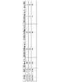
- FIG. 2 is a diagram showing an example of a data table.
- the date, time, amount of wastewater, amount of coagulant used, amount of neutralizer used, amount of sludge generated, and turbidity of water in the coagulation tank 102 Is associated with.
- Each of these pieces of information is information contained in a signal relating to water treatment received from the gateway device 27 by the communication device 50.
- the time is, for example, an hourly time.
- the amount of wastewater is the amount of treated water discharged from the water treatment system 2 per hour, and is substantially equal to the amount of raw water entering the water treatment system 2 per hour.
- the addition rate of the coagulant and the addition rate of the neutralizing agent may be further associated with each other.
- the information processing unit 53 is a functional unit that executes information processing.
- the information processing unit 53 includes an authentication unit 530, a control unit 531, a reduction amount derivation unit 532, a reduction amount derivation unit 533, and a creation unit 534.
- the authentication unit 530 is a functional unit that executes a user authentication process.
- the control unit 531 generates an image of the portal site for the customer authenticated in the user authentication process.
- the control unit 531 transmits the image of the portal site for the authenticated customer to the gateway device 27 or the information processing device 4 via the communication device 50.
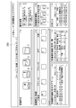
- FIG. 3 is a diagram showing a display example of a portal site for customers.
- the image of the portal site for the customer is displayed on the display unit of the water treatment control device 20 or the information processing device 4 of the authenticated customer.
- the image of the portal site for the customer includes an image showing the equipment status of the water treatment system 2, an image showing the remaining amount of chemicals, and a key image 200.
- the information processing device 4 transmits a report creation command regarding water treatment to the report creation device 5.
- the gateway device 27 transmits a report creation command regarding water treatment to the report creation device 5.
- the control unit 531 instructs the reduction amount derivation unit 532, the reduction amount derivation unit 533, and the preparation unit 534 to create a report regarding water treatment. ..
- the reduction amount derivation unit 532 acquires information on the treatment amount related to water treatment (hereinafter referred to as “reference treatment amount”) measured in advance before the target period from the storage device 52.
- the reduction amount derivation unit 532 acquires information on the processing amount related to water treatment (hereinafter referred to as “treatment amount within the period”) measured in the target period from the storage device 52.
- treatment amount within the period is the information included in the signal related to water treatment received from the gateway device 27 by the communication device 50.
- the reduction amount derivation unit 532 derives the reduction amount of the treatment amount within the period in the target period with respect to the reference treatment amount based on the signal related to the water treatment in the water treatment system 2. For example, the reduction amount deriving unit 532 derives at least one reduction amount of the amount of the flocculant used, the amount of the neutralizing agent used, and the amount of sludge generated. The reduction amount derivation unit 532 may derive the reduction amount or the processing amount in the target period on a daily basis, or may derive the cumulative value of the reduction amount or the processing amount in the target period.
- the reduction amount derivation unit 533 acquires the data of the reference processing amount from the storage device 52.
- the reduction amount derivation unit 533 acquires the data of the processing amount within the period from the storage device 52.
- the reduction amount derivation unit 533 acquires at least one data of the unit price of the coagulant, the unit price of the neutralizing agent, and the unit price of the sludge disposal cost from the storage device 52.
- the reduction amount derivation unit 533 derives the difference between the reference amount and the amount within the period in the target period. That is, the reduction amount derivation unit 533 derives the reduction amount of the amount within the period in the target period with respect to the reference amount.
- Creation department 534 creates a report showing the amount of reduction (cost merit) during the target period.
- the preparation unit 534 may further create a report showing the amount within the period in the target period and the reference amount.
- the preparation unit 534 may further create a report that further represents a time-series graph (trend graph) of water quality during the target period.
- the data of the created report is transmitted to the water treatment system 2 or the information processing apparatus 4 that ordered the creation of the report.
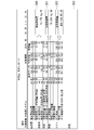
- FIG. 4 is a diagram showing the first example of the monthly report.
- the standard amount (“cost” in “basic data”)
- the amount within the period (“cost” in “October results”)
- the reduction amount (“cost” in “reduction amount”) are shown. They are associated with each other.
- the display area 300 is an area for displaying the amount of chemical reduction (chemical reduction amount).
- the display area 301 is an area for displaying the amount of reduction in the amount of sludge generated (sludge reduction amount).
- the display area 302 is an area for displaying the total cost reduction amount (total reduction cost).
- the display area 303 is an area for displaying findings regarding the contents of the monthly report. This finding is recorded in the monthly report by, for example, the administrator of the report creation device 5.
- the water quality condition is, for example, a condition that the turbidity of the treated water is maintained at a low level.
- FIG. 5 is a diagram showing a second example of the monthly report.
- the monthly report shown in FIG. 5 further includes an average value information, a trend graph and a graph of aggregated data as compared to the monthly report shown in FIG.
- the average value information is information on the average value such as turbidity per hour in the target period.
- the trend graph represents a time-series graph of displacement, a time-series graph of coagulant (polyiron), and a time-series graph of turbidity.
- the graph of the aggregated data is a graph showing the amount of chemicals used on a daily basis.
- FIG. 6 is a flowchart showing an operation example of the report creation device 5.
- the reduction amount derivation unit 533 acquires the data of the reference processing amount measured before the predetermined target period (step S101). The reduction amount derivation unit 533 acquires the data of the processing amount within the period measured in the predetermined target period (step S102). The reduction amount derivation unit 533 acquires at least one data of the unit price of the coagulant, the unit price of the neutralizing agent, and the unit price of the sludge disposal cost (step S103). The reduction amount derivation unit 533 derives the standard amount based on the standard processing amount and each unit price (step S104). The reduction amount derivation unit 533 derives the amount within the period based on the processing amount within the period and each unit price (step S105).
- the reduction amount derivation unit 533 derives the reduction amount of the amount within the period with respect to the reference amount (step S106).
- the preparation unit 534 creates a report showing the reduction amount in the target period (step S107).
- the communication device 50 outputs the report created by the creation unit 534 to the gateway device 27 or the information processing device 4 that requested the report (step S108).
- the report creation device 5 of the embodiment includes a reduction amount derivation unit 533 and a creation unit 534.
- the reduction amount derivation unit 533 acquires the data of the reference processing amount which is the processing amount related to the water treatment measured in advance before the target period.
- the length of the target period is, for example, one month.
- the reduction amount derivation unit 533 acquires the data of the treatment amount within the period, which is the treatment amount related to the water treatment measured in the target period.
- the target period is a predetermined month (for example, the period of October).
- the reduction amount derivation unit 533 derives a reference amount which is an amount corresponding to the standard processing amount and an amount within the period which is an amount corresponding to the processing amount within the period.
- the reduction amount derivation unit 533 derives the reduction amount of the amount within the period with respect to the reference amount.
- the preparation unit 534 creates a report (monthly report) showing the reduction amount in the target period, as in the “total reduction cost” shown in FIG.
- the reduction amount derivation unit 533 derives, for example, the reduction amount for at least one of the amount of coagulant used, the amount of neutralizing agent used, and the amount of sludge generated.
- the report creation device 5 may further include a reduction amount derivation unit 532.
- the reduction amount derivation unit 532 may derive at least one reduction amount of the amount of the flocculant used, the amount of the neutralizing agent used, and the amount of sludge generated.
- the preparation unit 534 may further prepare a report showing the derived chemical reduction amount and sludge reduction amount as shown in FIG.
- the creation unit 534 may further create a report showing the standard amount (“cost” of “basic data”) and the amount within the period (“cost” of “October result”) as shown in FIG. ..
- the preparation unit 534 may further create a report that further represents a time-series graph (trend graph) of water quality such as turbidity, drainage amount, and usage amount during the target period.
- the creation unit 534 may create a report that further represents a graph of the aggregated data, as shown in FIG.
- the preparation unit 534 may create a report representing the character string "OK" or the like indicating that the water quality condition was satisfied during the target period. As a result, it is possible to show the customer that the water quality condition is satisfied while the actual cost value is reduced.
- the reduction amount derivation unit 532 may derive the reduction amount of the carbon dioxide emission amount in the water treatment system 2 with respect to a predetermined reference emission amount.
- the amount of carbon dioxide emitted is determined, for example, according to the amount of sludge generated.
- the reduction amount derivation unit 533 may, for example, derive the reduction amount according to the reduction amount of the carbon dioxide emission amount in the water treatment system 2.
- the report creation device 5 may create a report (monthly report) showing the amount of reduction in carbon dioxide emissions in the water treatment system 2.
- the reduction amount derivation unit 533 may derive a standard amount, which is an amount corresponding to the standard processing amount, for each target period. For example, when the reduction amount derivation unit 533 derives the reduction amount of the amount within the period of the target month, the amount within the period of the previous month of the target month may be used as the reference amount. The reduction amount derivation unit 533 derives the reduction amount of the amount within the period of October with respect to the reference amount based on the amount of money within the period of September, for example. As a result, the report creation device 5 can present the customer with a report representing the billing amount optimized for each target period. This billing amount is determined according to, for example, the reduction amount (cost merit).
- the reduction amount derivation unit 532 may derive the reduction amount of the human cost in the water treatment system 2 with respect to a predetermined reference treatment amount. Since the chemical injection control device 21 accurately controls the amount of chemicals used, the operator does not need to adjust the amount of chemicals used (labor saving), so that the human cost in the water treatment system 2 is reduced.
- the reduction amount derivation unit 533 may, for example, derive the reduction amount related to the labor cost in the water treatment system 2.
- the report creation device 5 may create a report (monthly report) showing the amount of reduction in labor costs in the water treatment system 2.
- the communication device 50 processes information at a predetermined timing of each month (for example, the timing of the beginning of the month following the target period).
- the report data created by the unit 53 may be transmitted to the gateway device 27 or the information processing device 4 by a push method.
- the present invention is applicable to a server device that creates a report on a water treatment system or the like.
Landscapes
- Business, Economics & Management (AREA)
- Engineering & Computer Science (AREA)
- Economics (AREA)
- Human Resources & Organizations (AREA)
- Strategic Management (AREA)
- Physics & Mathematics (AREA)
- Theoretical Computer Science (AREA)
- Entrepreneurship & Innovation (AREA)
- Health & Medical Sciences (AREA)
- Marketing (AREA)
- General Physics & Mathematics (AREA)
- General Business, Economics & Management (AREA)
- Tourism & Hospitality (AREA)
- Game Theory and Decision Science (AREA)
- Quality & Reliability (AREA)
- Operations Research (AREA)
- Educational Administration (AREA)
- Development Economics (AREA)
- Public Health (AREA)
- Water Supply & Treatment (AREA)
- General Health & Medical Sciences (AREA)
- Primary Health Care (AREA)
- Management, Administration, Business Operations System, And Electronic Commerce (AREA)
- Separation Of Suspended Particles By Flocculating Agents (AREA)
Abstract
レポート作成装置は、対象期間よりも前に予め測定された水処理に関する処理量である基準処理量のデータと、対象期間において測定された水処理に関する処理量である期間内処理量のデータとを取得し、基準処理量に応じた金額である基準金額と期間内処理量に応じた金額である期間内金額とを導出し、基準金額に対する期間内金額の削減額を導出する削減額導出部と、導出された削減額を表すレポートを作成する作成部とを備える。
Description
本発明は、レポート作成装置及びレポート作成方法に関する。
本願は、2019年5月9日に日本に出願された特願2019-089310号に基づき優先権を主張し、その内容をここに援用する。
本願は、2019年5月9日に日本に出願された特願2019-089310号に基づき優先権を主張し、その内容をここに援用する。
水処理システムでは、凝集槽における濁質の凝集状態を検出するセンサが用いられることによって、凝集状態に影響する薬品の注入量が精度よく制御可能となった。これによって、水処理に使用される薬品等のコストが精度よく予測可能となった。そこで、水処理システムの導入を検討する顧客に対して、新たな水処理システムが導入された場合に削減可能なコストの予測値が提示される場合がある(特許文献1、2及び3参照)。
しかしながら、顧客は、新たな水処理システムが導入されたことによって削減されたコスト(削減額)の実績値を、分かり易い形式では知ることができなかった。すなわち、水処理システムが導入された場合に削減されたコストの実績値が顧客に分かり易く提示されない場合があった。
上記事情に鑑み、本発明は、水処理システムが導入された場合に削減されたコストの実績値を顧客に提示することが可能であるレポート作成装置及びレポート作成方法を提供することを目的としている。
本発明の一態様は、対象期間よりも前に予め測定された水処理に関する処理量である基準処理量のデータと、前記対象期間において測定された水処理に関する処理量である期間内処理量のデータとを取得し、前記基準処理量に応じた金額である基準金額と前記期間内処理量に応じた金額である期間内金額とを導出し、前記基準金額に対する前記期間内金額の削減額を導出する削減額導出部と、導出された前記削減額 を表すレポートを作成する作成部とを備えるレポート作成装置である。
本発明の一態様は、上記のレポート作成装置であって、前記削減額導出部は、凝集剤の使用量と中和剤の使用量と汚泥の発生量とのうちの少なくとも一つに関する前記削減額を導出する。
本発明の一態様は、上記のレポート作成装置であって、前記凝集剤の使用量と前記中和剤の使用量と前記汚泥の発生量とのうちの少なくとも一つの削減量を導出する削減量導出部を更に備え、前記作成部は、前記削減量を更に表すレポートを作成する。
本発明の一態様は、上記のレポート作成装置であって、前記作成部は、前記基準金額及び前記期間内金額を更に表すレポートを作成する。
本発明の一態様は、上記のレポート作成装置であって、前記作成部は、前記対象期間における水質の時系列のグラフを更に表すレポートを作成する。
本発明の一態様は、上記のレポート作成装置であって、前記対象期間の長さは、1か月間である。
本発明の一態様は、水処理に関するレポートを作成するレポート作成装置が実行するレポート作成方法であって、対象期間よりも前に予め測定された水処理に関する処理量である基準処理量のデータと、前記対象期間において測定された水処理に関する処理量である期間内処理量のデータとを取得し、前記基準処理量に応じた金額である基準金額と前記期間内処理量に応じた金額である期間内金額とを導出し、前記基準金額に対する前記期間内金額の削減額を導出する削減額導出ステップと、導出された前記削減額を表すレポートを作成する作成ステップとを含むレポート作成方法である。
本発明により、水処理システムが導入された場合に削減されたコストの実績値を顧客に提示することが可能である。
本発明の実施形態について、図面を参照して詳細に説明する。
図1は、水処理管理システム1の構成例を示す図である。水処理管理システム1は、水処理システムの運転を管理するシステム(リアルタイム・モニタリング・システム)である。水処理管理システム1は、水処理システム2と、通信回線3と、情報処理装置4と、レポート作成装置5とを備える。
図1は、水処理管理システム1の構成例を示す図である。水処理管理システム1は、水処理システムの運転を管理するシステム(リアルタイム・モニタリング・システム)である。水処理管理システム1は、水処理システム2と、通信回線3と、情報処理装置4と、レポート作成装置5とを備える。
水処理システム2は、原水に対して水処理を実行するシステムであり、例えば、浄水処理設備、下水処理設備、車両製造工場設備、化学工場設備又は製紙工場設備である。水処理システム2は、通信回線3を介して、水処理に関する信号をレポート作成装置5に送信する。通信回線3は、インターネット等の回線である。
情報処理装置4は、スマートフォン端末、タブレット端末、パーソナルコンピュータ等の情報処理装置である。情報処理装置4は、通信部と、液晶ディスプレイ等の表示部と、キーボード又はタッチパネル等の操作部とを備える。
情報処理装置4の通信部は、水処理システム2を運転する顧客用のポータルサイト(ウェブページ)の画像を、レポート作成装置5から受信する。顧客用のポータルサイトの画像は、例えば、HTML(HyperText Markup Language)等の言語を用いて記述されている。情報処理装置4の表示部は、顧客用(情報処理装置4のユーザ用)のポータルサイトの画像を表示する。
顧客用のポータルサイトの画像には、例えば、水処理システム2における水処理に関するトレンドグラフと、薬品タンク内の薬品量を表す情報とが含まれている。顧客用のポータルサイトの画像には、顧客用のポータルサイトのユーザ認証用の画像と、水処理システム2における水処理に関するレポートの画像とが含まれていてもよい。
情報処理装置4の操作部は、情報処理装置4のユーザ(顧客)による操作を受け付ける。ユーザによる操作とは、例えば、顧客用のポータルサイトのユーザ認証のための識別番号及びパスワード情報をレポート作成装置5に送信するための操作、水処理に関するレポートの作成命令をレポート作成装置5に送信するための操作である。情報処理装置4は、水処理に関するレポートの作成命令を、情報処理装置4のユーザによる操作に応じて例えば1か月ごとに送信する。
レポート作成装置5は、水処理システム2における水処理に関するレポートを作成する情報処理装置であり、例えば、サーバ装置である。レポート作成装置5は、例えば、水処理システム2における水処理に関する月次レポートを作成する。月次レポートには、レポートの対象月間における削減額が記載されている。この削減額とは、例えば、水処理システム2にセンサ25が設置されていない場合のコストを基準として、水処理システム2にセンサ25が設置されている場合(新たな水処理システムが導入された場合)に削減されたコスト(削減額)の実績値である。このコストとは、例えば、凝集剤の使用量と中和剤の使用量と汚泥の発生量とに応じた処理コスト(金額)である。汚泥の発生量は、凝集剤及び中和剤の使用量と、凝集剤及び中和剤の種類と、汚泥の含水率とに応じて定まる。
次に、水処理システム2の詳細を説明する。
水処理システム2は、反応槽100と、調整槽101と、凝集槽102と、沈殿槽103とを備える。水処理システム2は、水処理制御装置20と、薬注制御装置21と、第1凝集剤注入装置22と、調整剤注入装置23と、第2凝集剤注入装置24と、センサ25と、脱水剤注入装置26と、ゲートウェイ装置27とを備える。
水処理システム2は、反応槽100と、調整槽101と、凝集槽102と、沈殿槽103とを備える。水処理システム2は、水処理制御装置20と、薬注制御装置21と、第1凝集剤注入装置22と、調整剤注入装置23と、第2凝集剤注入装置24と、センサ25と、脱水剤注入装置26と、ゲートウェイ装置27とを備える。
反応槽100では、無機凝集剤又は有機凝集剤が原水に注入される。反応槽100の水は、調整槽101に送られる。調整槽101の水には、中和剤(pH調整剤)が注入される。調整槽101の水は、凝集槽102に送られる。凝集槽102の水には、高分子凝集剤が注入される。凝集槽102の水は、沈殿槽103に送られる。沈殿槽103の水では、汚泥(sludge)が沈殿する。沈殿槽103は、汚泥が分離された水(処理水)を、所定の水槽に送る。
水処理制御装置20は、水処理に関する制御を実行する情報処理装置であり、例えば、パーソナルコンピュータ、ワークステーションである。水処理制御装置20は、運転信号を薬注制御装置21に出力する。運転信号は、例えば、薬品の注入タイミングを表す信号を含む。水処理制御装置20は、薬品の注入量を表す信号を、薬注制御装置21から取得してもよい。水処理制御装置20は、水処理に関する信号を、ゲートウェイ装置27に出力する。水処理に関する信号は、例えば、薬品の注入量の情報と、センサ25による水質検出結果の情報と、排水量の情報とを含む。
水処理制御装置20は、顧客用のポータルサイトの画像を、ゲートウェイ装置27を介してレポート作成装置5から取得してもよい。水処理制御装置20の表示部は、顧客用のポータルサイトの画像を表示してもよい。
薬注制御装置21は、薬品の注入量を制御する装置であり、例えば、プログラマブル・ロジック・コントローラ(programmable logic controller : PLC)である。薬注制御装置21は、運転信号を水処理制御装置20から受信した場合、薬品の注入量を制御する。薬注制御装置21は、凝集槽102の水に含まれている濁質の凝集状態に応じて、第1凝集剤注入装置22と調整剤注入装置23と第2凝集剤注入装置24と脱水剤注入装置26とのうちの少なくとも一つに、薬品の注入量を制御するための信号(以下「薬注制御信号」という。)を出力する。
第1凝集剤注入装置22は、無機凝集剤又は有機凝集剤を反応槽100に注入する装置であり、例えば、電動ポンプである。第1凝集剤注入装置22は、薬注制御信号に基づく量の無機凝集剤又は有機凝集剤を、反応槽100に注入する。第1凝集剤注入装置22は、例えば、ポリ塩化アルミニウム(Poly Aluminium Chloride : PAC)又は塩化鉄ポリ鉄を、反応槽100に注入する。
調整剤注入装置23は、中和剤を調整槽101に注入する装置であり、例えば、電動ポンプである。調整剤注入装置23は、薬注制御信号に基づく量の中和剤を、調整槽101に注入する。第2凝集剤注入装置24は、高分子凝集剤を凝集槽102に注入する装置であり、例えば、電動ポンプである。第2凝集剤注入装置24は、薬注制御信号に基づく量の高分子凝集剤を、調整槽101に注入する。
センサ25は、濁質の凝集状態(濁度等の水質)を検出する装置である。センサ25は、凝集槽102の水に含まれている濁質の凝集状態を検出する。センサ25は、濁質の凝集状態を表す信号を、薬注制御装置21に出力する。脱水剤注入装置26は、脱水剤を汚泥に注入する装置であり、例えば、電動ポンプである。脱水剤注入装置26は、薬注制御信号に基づく量の脱水剤を汚泥に注入する。
ゲートウェイ装置27は、通信装置である。ゲートウェイ装置27は、TCP/IP(Transmission Control Protocol / Internet Protocol)等のプロトコルに従って、通信回線3を介してレポート作成装置5と通信する。ゲートウェイ装置27は、水処理システム2における水処理に関する信号を、レポート作成装置5に送信する。
ゲートウェイ装置27は、顧客用のポータルサイトのユーザ認証のための識別番号及びパスワード情報を、レポート作成装置5に送信してもよい。ゲートウェイ装置27は、顧客用のポータルサイトの画像を、レポート作成装置5から取得してもよい。ゲートウェイ装置27は、水処理システム2における水処理に関するレポートを、レポート作成装置5から取得してもよい。
次に、レポート作成装置5の詳細を説明する。
レポート作成装置5は、通信装置50と、バス51と、記憶装置52と、情報処理部53とを備える。レポート作成装置5の各機能部の一部又は全部は、CPU(Central Processing Unit)又はGPU(Graphics Processing Unit)等のプロセッサが、不揮発性の記録媒体(非一時的な記録媒体)である記憶装置52に記憶されたプログラムを実行することにより、ソフトウェアとして実現される。レポート作成装置5の各機能部の一部又は全部は、例えば、LSI(Large Scale Integration)又はFPGA(Field Programmable Gate Array)等のハードウェアを用いて実現されてもよい。
レポート作成装置5は、通信装置50と、バス51と、記憶装置52と、情報処理部53とを備える。レポート作成装置5の各機能部の一部又は全部は、CPU(Central Processing Unit)又はGPU(Graphics Processing Unit)等のプロセッサが、不揮発性の記録媒体(非一時的な記録媒体)である記憶装置52に記憶されたプログラムを実行することにより、ソフトウェアとして実現される。レポート作成装置5の各機能部の一部又は全部は、例えば、LSI(Large Scale Integration)又はFPGA(Field Programmable Gate Array)等のハードウェアを用いて実現されてもよい。
通信装置50は、TCP/IP等のプロトコルに従って、通信回線3を介してゲートウェイ装置27及び情報処理装置4と通信する。通信装置50は、顧客用のポータルサイトのユーザ認証のための識別番号及びパスワード情報を、ゲートウェイ装置27又は情報処理装置4から取得する。通信装置50は、情報処理部53によって認証された顧客用のポータルサイトの画像を、ゲートウェイ装置27又は情報処理装置4に送信する。通信装置50は、情報処理部53によって作成されたレポートを、レポートを要求したゲートウェイ装置27又は情報処理装置4に送信する。バス51は、レポート作成装置5の各機能部及び記憶装置52の間のデータを伝送する。
記憶装置52は、プログラムを記憶する。記憶装置52は、顧客用のポータルサイトのパスワード情報と、データテーブルとを、顧客ごとに記憶する。データテーブルは、例えば、通信装置50によってゲートウェイ装置27から受信された水処理に関する信号に含まれていた情報を含む。
図2は、データテーブルの例を示す図である。図2に示されたデータテーブルでは、年月日と、時刻と、排水量と、凝集剤の使用量と、中和剤の使用量と、汚泥の発生量と、凝集槽102の水の濁度とが対応付けられている。これらの各情報は、通信装置50によってゲートウェイ装置27から受信された水処理に関する信号に含まれていた情報である。
時刻は、一例として1時間ごとの時刻である。排水量は、1時間あたりで水処理システム2から排出された処理水の量であり、1時間あたりで水処理システム2に入った原水の量にほぼ等しい。なお、データテーブルでは、凝集剤の添加率と、中和剤の添加率とが更に対応付けられていてもよい。
図1に戻り、水処理管理システム1の構成例の説明を続ける。情報処理部53は、情報処理を実行する機能部である。情報処理部53は、認証部530と、制御部531と、削減量導出部532と、削減額導出部533と、作成部534とを備える。認証部530は、ユーザ認証処理を実行する機能部である。制御部531は、ユーザ認証処理において認証された顧客用のポータルサイトの画像を生成する。制御部531は、認証された顧客用のポータルサイトの画像を、通信装置50を介してゲートウェイ装置27又は情報処理装置4に送信する。
図3は、顧客用のポータルサイトの表示例を示す図である。顧客用のポータルサイトの画像は、認証された顧客の水処理制御装置20又は情報処理装置4の表示部に表示される。顧客用のポータルサイトの画像には、水処理システム2の設備状況を表す画像と、薬品残量を表す画像と、キー画像200とが含まれている。
情報処理装置4のユーザによってキー画像200が操作された場合、情報処理装置4は、水処理に関するレポートの作成命令を、レポート作成装置5に送信する。水処理システム2のユーザによってキー画像200が操作された場合、ゲートウェイ装置27は、水処理に関するレポートの作成命令を、レポート作成装置5に送信する。
レポート作成装置5では、制御部531は、水処理に関するレポートの作成命令を取得した場合、水処理に関するレポートの作成を、削減量導出部532と削減額導出部533と作成部534とに指示する。削減量導出部532は、対象期間よりも前に予め測定された水処理に関する処理量(以下「基準処理量」という。)の情報を、記憶装置52から取得する。削減量導出部532は、対象期間において測定された水処理に関する処理量(以下「期間内処理量」という。)の情報を、記憶装置52から取得する。期間内処理量の情報は、通信装置50によってゲートウェイ装置27から受信された水処理に関する信号に含まれていた情報である。
削減量導出部532は、水処理システム2における水処理に関する信号に基づいて、基準処理量に対する、対象期間における期間内処理量の削減量を導出する。例えば、削減量導出部532は、凝集剤の使用量と中和剤の使用量と汚泥の発生量とのうちの少なくとも一つの削減量を導出する。なお、削減量導出部532は、対象期間における削減量又は処理量を日ごとに導出してもよいし、対象期間における削減量又は処理量の累積値を導出してもよい。
削減額導出部533は、基準処理量のデータを記憶装置52から取得する。削減額導出部533は、期間内処理量のデータを記憶装置52から取得する。削減額導出部533は、凝集剤の単価と中和剤の単価と汚泥処分費用の単価とのうちの少なくとも一つのデータを、記憶装置52から取得する。
削減額導出部533は、基準処理量及び各単価に基づいて、基準金額(=基準処理量×単価)を導出する。削減額導出部533は、期間内処理量及び各単価に基づいて、期間内金額(=期間内処理量×単価)を導出する。削減額導出部533は、基準金額と対象期間における期間内金額との差額を導出する。すなわち、削減額導出部533は、基準金額に対する、対象期間における期間内金額の削減額を導出する。
作成部534は、対象期間における削減額(コストのメリット)を表すレポートを作成する。作成部534は、対象期間における期間内金額と、基準金額とを更に表すレポートを作成してもよい。作成部534は、対象期間における水質の時系列のグラフ(トレンドグラフ)を更に表すレポートを作成してもよい。作成されたレポートのデータは、レポートの作成を命令した水処理システム2又は情報処理装置4に送信される。
図4は、月次レポートの第1例を示す図である。月次レポートでは、基準金額(「基本データ」の「コスト」)と、期間内金額(「10月実績」の「コスト」)と、削減額(「削減量」の「コスト」)とが、互いに対応付けられている。
表示領域300は、薬品の削減量(薬品削減量)を表示するための領域である。表示領域301は、汚泥の発生量の削減量(汚泥削減量)を表示するための領域である。表示領域302は、コストの削減額の合計(合計削減費)を表示するための領域である。表示領域303は、月次レポートの内容に関する所見を表示する領域である。この所見は、例えば、レポート作成装置5の管理者によって月次レポートに記入される。
なお、月次レポートが顧客に提示される場合、対象期間において水質の条件が満たされていたことを表す情報と、削減額とが、顧客に提示されてもよい。水質の条件とは、例えば、処理水の濁度が低レベルを維持しているという条件である。
図5は、月次レポートの第2例を示す図である。図5に示された月次レポートは、図4に示された月次レポートと比較して、平均値情報とトレンドグラフと集計データのグラフとを更に含む。平均値情報は、対象期間における1時間あたりの濁度等の平均値の情報である。トレンドグラフは、排水量の時系列のグラフと、凝集剤(ポリ鉄)の時系列のグラフと、濁度の時系列のグラフとを表す。集計データのグラフは、薬品の使用量を日ごとに表すグラフである。
次に、レポート作成装置5の動作例を説明する。
図6は、レポート作成装置5の動作例を示すフローチャートである。レポート作成装置5は、レポートの作成命令を水処理システム2又は情報処理装置4から受信した場合、図6に示された動作手順を実行する。
図6は、レポート作成装置5の動作例を示すフローチャートである。レポート作成装置5は、レポートの作成命令を水処理システム2又は情報処理装置4から受信した場合、図6に示された動作手順を実行する。
削減額導出部533は、所定の対象期間よりも前に測定された基準処理量のデータを取得する(ステップS101)。削減額導出部533は、所定の対象期間に測定された期間内処理量のデータを取得する(ステップS102)。削減額導出部533は、凝集剤の単価と中和剤の単価と汚泥処分費用の単価とのうちの少なくとも一つのデータを取得する(ステップS103)。削減額導出部533は、基準処理量及び各単価に基づいて、基準金額を導出する(ステップS104)。削減額導出部533は、期間内処理量及び各単価に基づいて、期間内金額を導出する(ステップS105)。
削減額導出部533は、基準金額に対する期間内金額の削減額を導出する(ステップS106)。作成部534は、対象期間における削減額を表すレポートを作成する(ステップS107)。通信装置50は、作成部534によって作成されたレポートを、レポートを要求したゲートウェイ装置27又は情報処理装置4に出力する(ステップS108)。
以上のように、実施形態のレポート作成装置5は、削減額導出部533と、作成部534とを備える。削減額導出部533は、対象期間よりも前に予め測定された水処理に関する処理量である基準処理量のデータを取得する。対象期間の長さは、例えば1か月間である。削減額導出部533は、対象期間において測定された水処理に関する処理量である期間内処理量のデータを取得する。対象期間は、予め定められた月間(例えば、10月の期間)である。削減額導出部533は、基準処理量に応じた金額である基準金額と、期間内処理量に応じた金額である期間内金額とを導出する。削減額導出部533は、基準金額に対する期間内金額の削減額を導出する。作成部534は、図4に示された「合計削減費」のように、対象期間における削減額を表すレポート(月次レポート)を作成する。
これによって、水処理システム2が導入されない場合と比較して、水処理システム2が導入された場合に削減されたコストの実績値を、顧客(ユーザ)に対して提示することが可能である。
削減額導出部533は、例えば、凝集剤の使用量と中和剤の使用量と汚泥の発生量とのうちの少なくとも一つに関する削減額を導出する。レポート作成装置5は、削減量導出部532を更に備えてもよい。削減量導出部532は、凝集剤の使用量と中和剤の使用量と汚泥の発生量とのうちの少なくとも一つの削減量を導出してもよい。作成部534は、導出された薬品削減量及び汚泥削減量を更に表すレポートを、図4のように作成してもよい。
作成部534は、基準金額(「基本データ」の「コスト」)と、期間内金額(「10月実績」の「コスト」)とを更に表すレポートを、図4のように作成してもよい。作成部534は、図5のように、対象期間における濁度等の水質と排水量と使用量との時系列のグラフ(トレンドグラフ)を更に表すレポートを作成してもよい。作成部534は、図5のように、集計データのグラフを更に表すレポートを作成してもよい。作成部534は、対象期間において水質の条件が満たされていたことを表す文字列「OK」等を表すレポートを作成してもよい。これによって、コストの実績値が削減された上で水質の条件が満たされていたことを顧客に提示することが可能である。
(第1の変形例)
削減量導出部532は、所定の基準排出量に対して、水処理システム2における二酸化炭素の排出量の削減量を導出してもよい。二酸化炭素の排出量は、例えば、汚泥の発生量に応じて定まる。削減額導出部533は、例えば、水処理システム2における二酸化炭素の排出量の削減量に応じた削減額を導出してもよい。レポート作成装置5は、水処理システム2における二酸化炭素の排出量の削減量を表すレポート(月次レポート)を作成してもよい。
削減量導出部532は、所定の基準排出量に対して、水処理システム2における二酸化炭素の排出量の削減量を導出してもよい。二酸化炭素の排出量は、例えば、汚泥の発生量に応じて定まる。削減額導出部533は、例えば、水処理システム2における二酸化炭素の排出量の削減量に応じた削減額を導出してもよい。レポート作成装置5は、水処理システム2における二酸化炭素の排出量の削減量を表すレポート(月次レポート)を作成してもよい。
(第2の変形例)
削減額導出部533は、基準処理量に応じた金額である基準金額を、対象期間ごとに導出してもよい。例えば、削減額導出部533は、対象月間の期間内金額の削減額を導出する場合、対象月間の前月の期間内金額を基準金額としてもよい。削減額導出部533は、例えば9月の期間内金額に基づく基準金額に対する、10月の期間内金額の削減額を導出する。これによって、レポート作成装置5は、対象期間ごとに最適化された請求金額を表すレポートを、顧客に提示することができる。この請求金額は、例えば、削減額(コストのメリット)に応じて定められる。
削減額導出部533は、基準処理量に応じた金額である基準金額を、対象期間ごとに導出してもよい。例えば、削減額導出部533は、対象月間の期間内金額の削減額を導出する場合、対象月間の前月の期間内金額を基準金額としてもよい。削減額導出部533は、例えば9月の期間内金額に基づく基準金額に対する、10月の期間内金額の削減額を導出する。これによって、レポート作成装置5は、対象期間ごとに最適化された請求金額を表すレポートを、顧客に提示することができる。この請求金額は、例えば、削減額(コストのメリット)に応じて定められる。
(第3の変形例)
削減量導出部532は、所定の基準処理量に対して、水処理システム2における人的コストの削減量を導出してもよい。薬注制御装置21が薬品の使用量を精度よく制御するので、薬品の使用量を運転員が調整する必要がないため(業務省力化)、水処理システム2における人的コストは削減される。削減額導出部533は、例えば、水処理システム2における人件費に関する削減額を導出してもよい。レポート作成装置5は、水処理システム2における人件費に関する削減額を表すレポート(月次レポート)を作成してもよい。
削減量導出部532は、所定の基準処理量に対して、水処理システム2における人的コストの削減量を導出してもよい。薬注制御装置21が薬品の使用量を精度よく制御するので、薬品の使用量を運転員が調整する必要がないため(業務省力化)、水処理システム2における人的コストは削減される。削減額導出部533は、例えば、水処理システム2における人件費に関する削減額を導出してもよい。レポート作成装置5は、水処理システム2における人件費に関する削減額を表すレポート(月次レポート)を作成してもよい。
(第4の変形例)
ゲートウェイ装置27又は情報処理装置4がレポートの作成を要求していない場合でも、例えば毎月の所定タイミング(例えば、対象期間である月間の次月の月初のタイミング)で、通信装置50は、情報処理部53によって作成されたレポートのデータを、プッシュ方式でゲートウェイ装置27又は情報処理装置4に送信してもよい。
ゲートウェイ装置27又は情報処理装置4がレポートの作成を要求していない場合でも、例えば毎月の所定タイミング(例えば、対象期間である月間の次月の月初のタイミング)で、通信装置50は、情報処理部53によって作成されたレポートのデータを、プッシュ方式でゲートウェイ装置27又は情報処理装置4に送信してもよい。
以上、この発明の実施形態について図面を参照して詳述してきたが、具体的な構成はこの実施形態に限られるものではなく、この発明の要旨を逸脱しない範囲の設計等も含まれる。
本発明は、水処理システム等に関するレポートを作成するサーバ装置に適用可能である。
1…水処理管理システム、2…水処理システム、3…通信回線、4…情報処理装置、5…レポート作成装置、20…水処理制御装置、21…薬注制御装置、22…第1凝集剤注入装置、23…調整剤注入装置、24…第2凝集剤注入装置、25…センサ、26…脱水剤注入装置、100…反応槽、101…調整槽、102…凝集槽、103…沈殿槽、50…通信装置、51…バス、52…記憶装置、53…情報処理部、200…キー画像、300…表示領域、301…表示領域、302…表示領域、303…表示領域、530…認証部、531…制御部、532…削減量導出部、533…削減額導出部、534…作成部
Claims (7)
- 対象期間よりも前に予め測定された水処理に関する処理量である基準処理量のデータと、前記対象期間において測定された水処理に関する処理量である期間内処理量のデータとを取得し、前記基準処理量に応じた金額である基準金額と前記期間内処理量に応じた金額である期間内金額とを導出し、前記基準金額に対する前記期間内金額の削減額を導出する削減額導出部と、
導出された前記削減額を表すレポートを作成する作成部と
を備えるレポート作成装置。 - 前記削減額導出部は、凝集剤の使用量と中和剤の使用量と汚泥の発生量とのうちの少なくとも一つに関する前記削減額を導出する、
請求項1に記載のレポート作成装置。 - 前記凝集剤の使用量と前記中和剤の使用量と前記汚泥の発生量とのうちの少なくとも一つの削減量を導出する削減量導出部を更に備え、
前記作成部は、前記削減量を更に表すレポートを作成する、
請求項2に記載のレポート作成装置。 - 前記作成部は、前記基準金額及び前記期間内金額を更に表すレポートを作成する、
請求項1に記載のレポート作成装置。 - 前記作成部は、前記対象期間における水質の時系列のグラフを更に表すレポートを作成する、
請求項1に記載のレポート作成装置。 - 前記対象期間の長さは、1か月間である、
請求項1に記載のレポート作成装置。 - 水処理に関するレポートを作成するレポート作成装置が実行するレポート作成方法であって、
対象期間よりも前に予め測定された水処理に関する処理量である基準処理量のデータと、前記対象期間において測定された水処理に関する処理量である期間内処理量のデータとを取得し、前記基準処理量に応じた金額である基準金額と前記期間内処理量に応じた金額である期間内金額とを導出し、前記基準金額に対する前記期間内金額の削減額を導出する削減額導出ステップと、
導出された前記削減額を表すレポートを作成する作成ステップと
を含むレポート作成方法。
Applications Claiming Priority (2)
| Application Number | Priority Date | Filing Date | Title |
|---|---|---|---|
| JP2019-089310 | 2019-05-09 | ||
| JP2019089310A JP7061984B2 (ja) | 2019-05-09 | 2019-05-09 | レポート作成装置及びレポート作成方法 |
Publications (1)
| Publication Number | Publication Date |
|---|---|
| WO2020225976A1 true WO2020225976A1 (ja) | 2020-11-12 |
Family
ID=73050591
Family Applications (1)
| Application Number | Title | Priority Date | Filing Date |
|---|---|---|---|
| PCT/JP2020/011037 Ceased WO2020225976A1 (ja) | 2019-05-09 | 2020-03-13 | レポート作成装置及びレポート作成方法 |
Country Status (2)
| Country | Link |
|---|---|
| JP (1) | JP7061984B2 (ja) |
| WO (1) | WO2020225976A1 (ja) |
Families Citing this family (1)
| Publication number | Priority date | Publication date | Assignee | Title |
|---|---|---|---|---|
| JP7759830B2 (ja) * | 2021-06-29 | 2025-10-24 | オルガノ株式会社 | 情報処理システム、情報処理装置、情報処理方法およびプログラム |
Citations (8)
| Publication number | Priority date | Publication date | Assignee | Title |
|---|---|---|---|---|
| JP2002133044A (ja) * | 2000-10-30 | 2002-05-10 | Kubota Corp | プラント施設管理サービスシステム |
| JP2003114718A (ja) * | 2001-10-04 | 2003-04-18 | Kurita Water Ind Ltd | 設備管理システム |
| JP2005288361A (ja) * | 2004-04-01 | 2005-10-20 | Jfe Engineering Kk | 汚泥減量化支援システム |
| JP2008059144A (ja) * | 2006-08-30 | 2008-03-13 | Toshiba Corp | 運転評価システム |
| JP2010061273A (ja) * | 2008-09-02 | 2010-03-18 | Tsukishima Kikai Co Ltd | コスト算出装置、コスト算出方法、プログラム |
| JP2010179294A (ja) * | 2009-02-05 | 2010-08-19 | Shoei:Kk | 濾過装置ユニット、入浴アトラクション付の浴槽又はプール及び水景施設の省エネルギー機器のデータ管理・遠隔データ管理システム・方法・管理プログラム、並びにそのプログラムを記録したコンピュータ読み取り可能な記録媒体 |
| US20110022241A1 (en) * | 2009-07-23 | 2011-01-27 | Robert Higgins | Qualification system and method for chilled water plant operations |
| JP2011020069A (ja) * | 2009-07-17 | 2011-02-03 | Panasonic Corp | 汚泥削減手段の運用方法と装置 |
Family Cites Families (2)
| Publication number | Priority date | Publication date | Assignee | Title |
|---|---|---|---|---|
| US20060065606A1 (en) * | 2004-03-05 | 2006-03-30 | Ultrastrip Systems, Inc. | Modular wastewater remediation system and method of using |
| JP2008234070A (ja) * | 2007-03-16 | 2008-10-02 | Idemitsu Kosan Co Ltd | 運用管理システム、運用管理方法、そのプログラム、および、そのプログラムを記録した記録媒体 |
-
2019
- 2019-05-09 JP JP2019089310A patent/JP7061984B2/ja active Active
-
2020
- 2020-03-13 WO PCT/JP2020/011037 patent/WO2020225976A1/ja not_active Ceased
Patent Citations (8)
| Publication number | Priority date | Publication date | Assignee | Title |
|---|---|---|---|---|
| JP2002133044A (ja) * | 2000-10-30 | 2002-05-10 | Kubota Corp | プラント施設管理サービスシステム |
| JP2003114718A (ja) * | 2001-10-04 | 2003-04-18 | Kurita Water Ind Ltd | 設備管理システム |
| JP2005288361A (ja) * | 2004-04-01 | 2005-10-20 | Jfe Engineering Kk | 汚泥減量化支援システム |
| JP2008059144A (ja) * | 2006-08-30 | 2008-03-13 | Toshiba Corp | 運転評価システム |
| JP2010061273A (ja) * | 2008-09-02 | 2010-03-18 | Tsukishima Kikai Co Ltd | コスト算出装置、コスト算出方法、プログラム |
| JP2010179294A (ja) * | 2009-02-05 | 2010-08-19 | Shoei:Kk | 濾過装置ユニット、入浴アトラクション付の浴槽又はプール及び水景施設の省エネルギー機器のデータ管理・遠隔データ管理システム・方法・管理プログラム、並びにそのプログラムを記録したコンピュータ読み取り可能な記録媒体 |
| JP2011020069A (ja) * | 2009-07-17 | 2011-02-03 | Panasonic Corp | 汚泥削減手段の運用方法と装置 |
| US20110022241A1 (en) * | 2009-07-23 | 2011-01-27 | Robert Higgins | Qualification system and method for chilled water plant operations |
Also Published As
| Publication number | Publication date |
|---|---|
| JP2020187386A (ja) | 2020-11-19 |
| JP7061984B2 (ja) | 2022-05-02 |
Similar Documents
| Publication | Publication Date | Title |
|---|---|---|
| US10640404B2 (en) | Water treatment system and method | |
| DE102017220367B4 (de) | Programm-Aktualisierungssteuersystem und Programm-Aktualisierungssteuerverfahren | |
| KR101959862B1 (ko) | 사용자 디바이스 브라우저와 로컬 디바이스 사이의 통신을 가능하게 하는 방법 | |
| RU2012127289A (ru) | Устройство для обработки изображений и способ управления им | |
| JP7061984B2 (ja) | レポート作成装置及びレポート作成方法 | |
| US11866348B2 (en) | System, apparatus, and method for treating wastewater in real time | |
| ATE475234T1 (de) | Verfahren und system zur verwaltung eines xml- dokuments | |
| JP7264697B2 (ja) | プラント運転支援システム及びプラント運転支援方法 | |
| JP2012043067A (ja) | 情報処理システム、Webサーバ、情報処理装置、それらの制御方法、及びプログラム | |
| JP2025500550A5 (ja) | ||
| US10666631B2 (en) | Distributed validation of credentials | |
| JP4906799B2 (ja) | 自動運転制御システム | |
| CN115838238B (zh) | 一种用于污泥脱水设备的加药方法、系统及设备 | |
| CN117850361A (zh) | 自动检测启动混凝动力学模型的工艺智能控制模型方法 | |
| US5246590A (en) | Water treatment to reduce fog levels controlled with streaming current detector | |
| JP2008194559A (ja) | 凝集剤注入制御装置 | |
| CN107037793A (zh) | 污水处理监控方法及系统 | |
| JP7814883B2 (ja) | 薬品注入支援システム、薬品注入支援方法、及びプログラム | |
| US8860987B2 (en) | Driver program | |
| TWI591464B (zh) | Equipment Management System | |
| Horváth et al. | Oscillations in the concentration of fluoride ions induced by a pH oscillator | |
| Fallah et al. | Chemical disinfection of secondary municipal wastewater effluents: Optimizing CT dose and tailing effects through high‐intensity mixing | |
| JP2024131272A (ja) | 水質管理方法、水質管理装置、水質管理システム、及び水質管理プログラム | |
| JP2001038342A (ja) | 水処理プロセスの運転方法および装置 | |
| KR102454792B1 (ko) | 스마트 하수처리용 응집제 원격 자동주입 장치 및 방법 |
Legal Events
| Date | Code | Title | Description |
|---|---|---|---|
| 121 | Ep: the epo has been informed by wipo that ep was designated in this application |
Ref document number: 20802643 Country of ref document: EP Kind code of ref document: A1 |
|
| NENP | Non-entry into the national phase |
Ref country code: DE |
|
| 122 | Ep: pct application non-entry in european phase |
Ref document number: 20802643 Country of ref document: EP Kind code of ref document: A1 |