WO2020218591A1 - 防水膜とこれを備える防水部材及び電子機器 - Google Patents
防水膜とこれを備える防水部材及び電子機器 Download PDFInfo
- Publication number
- WO2020218591A1 WO2020218591A1 PCT/JP2020/017858 JP2020017858W WO2020218591A1 WO 2020218591 A1 WO2020218591 A1 WO 2020218591A1 JP 2020017858 W JP2020017858 W JP 2020017858W WO 2020218591 A1 WO2020218591 A1 WO 2020218591A1
- Authority
- WO
- WIPO (PCT)
- Prior art keywords
- waterproof
- waterproof film
- less
- sound
- housing
- Prior art date
- Legal status (The legal status is an assumption and is not a legal conclusion. Google has not performed a legal analysis and makes no representation as to the accuracy of the status listed.)
- Ceased
Links
Images


Classifications
-
- H—ELECTRICITY
- H04—ELECTRIC COMMUNICATION TECHNIQUE
- H04R—LOUDSPEAKERS, MICROPHONES, GRAMOPHONE PICK-UPS OR LIKE ACOUSTIC ELECTROMECHANICAL TRANSDUCERS; ELECTRIC HEARING AIDS; PUBLIC ADDRESS SYSTEMS
- H04R1/00—Details of transducers, loudspeakers or microphones
- H04R1/02—Casings; Cabinets ; Supports therefor; Mountings therein
- H04R1/023—Screens for loudspeakers
-
- H—ELECTRICITY
- H04—ELECTRIC COMMUNICATION TECHNIQUE
- H04R—LOUDSPEAKERS, MICROPHONES, GRAMOPHONE PICK-UPS OR LIKE ACOUSTIC ELECTROMECHANICAL TRANSDUCERS; ELECTRIC HEARING AIDS; PUBLIC ADDRESS SYSTEMS
- H04R1/00—Details of transducers, loudspeakers or microphones
- H04R1/44—Special adaptations for subaqueous use, e.g. for hydrophone
-
- H—ELECTRICITY
- H04—ELECTRIC COMMUNICATION TECHNIQUE
- H04M—TELEPHONIC COMMUNICATION
- H04M1/00—Substation equipment, e.g. for use by subscribers
- H04M1/02—Constructional features of telephone sets
-
- H—ELECTRICITY
- H04—ELECTRIC COMMUNICATION TECHNIQUE
- H04R—LOUDSPEAKERS, MICROPHONES, GRAMOPHONE PICK-UPS OR LIKE ACOUSTIC ELECTROMECHANICAL TRANSDUCERS; ELECTRIC HEARING AIDS; PUBLIC ADDRESS SYSTEMS
- H04R1/00—Details of transducers, loudspeakers or microphones
- H04R1/02—Casings; Cabinets ; Supports therefor; Mountings therein
- H04R1/025—Arrangements for fixing loudspeaker transducers, e.g. in a box, furniture
-
- H—ELECTRICITY
- H04—ELECTRIC COMMUNICATION TECHNIQUE
- H04R—LOUDSPEAKERS, MICROPHONES, GRAMOPHONE PICK-UPS OR LIKE ACOUSTIC ELECTROMECHANICAL TRANSDUCERS; ELECTRIC HEARING AIDS; PUBLIC ADDRESS SYSTEMS
- H04R1/00—Details of transducers, loudspeakers or microphones
- H04R1/08—Mouthpieces; Microphones; Attachments therefor
- H04R1/083—Special constructions of mouthpieces
- H04R1/086—Protective screens, e.g. all weather or wind screens
-
- H—ELECTRICITY
- H05—ELECTRIC TECHNIQUES NOT OTHERWISE PROVIDED FOR
- H05K—PRINTED CIRCUITS; CASINGS OR CONSTRUCTIONAL DETAILS OF ELECTRIC APPARATUS; MANUFACTURE OF ASSEMBLAGES OF ELECTRICAL COMPONENTS
- H05K5/00—Casings, cabinets or drawers for electric apparatus
- H05K5/06—Hermetically-sealed casings
- H05K5/068—Hermetically-sealed casings having a pressure compensation device, e.g. membrane
-
- H—ELECTRICITY
- H05—ELECTRIC TECHNIQUES NOT OTHERWISE PROVIDED FOR
- H05K—PRINTED CIRCUITS; CASINGS OR CONSTRUCTIONAL DETAILS OF ELECTRIC APPARATUS; MANUFACTURE OF ASSEMBLAGES OF ELECTRICAL COMPONENTS
- H05K5/00—Casings, cabinets or drawers for electric apparatus
- H05K5/06—Hermetically-sealed casings
- H05K5/069—Other details of the casing, e.g. wall structure, passage for a connector, a cable, a shaft
-
- H—ELECTRICITY
- H04—ELECTRIC COMMUNICATION TECHNIQUE
- H04R—LOUDSPEAKERS, MICROPHONES, GRAMOPHONE PICK-UPS OR LIKE ACOUSTIC ELECTROMECHANICAL TRANSDUCERS; ELECTRIC HEARING AIDS; PUBLIC ADDRESS SYSTEMS
- H04R2499/00—Aspects covered by H04R or H04S not otherwise provided for in their subgroups
- H04R2499/10—General applications
- H04R2499/11—Transducers incorporated or for use in hand-held devices, e.g. mobile phones, PDA's, camera's
Definitions
- the present invention relates to a waterproof film, a waterproof member provided with the waterproof film, and an electronic device.
- the housing of the electronic device may be provided with an opening for allowing sound and gas to pass through.
- wearable devices such as smart watches, smartphones, mobile phones, and electronic devices such as cameras have voice functions, and voice conversion units such as microphones and speakers are provided inside the housing.
- the housing of the electronic device is usually provided with an opening (external sound transmission port), and the voice conversion unit is used to provide sound through the opening. It is housed in a housing so that sound can be transmitted between the conversion unit and the outside.
- the housing may be provided with an opening (vent) for the purpose of eliminating the pressure difference between the inside and the outside of the housing.
- a waterproof film that prevents water from entering is arranged so as to prevent water from entering from the outside to the inside of the housing through the opening.
- Patent Documents 1 and 2 disclose a polytetrafluoroethylene (hereinafter referred to as "PTFE") porous membrane that can be used as a waterproof membrane.
- PTFE polytetrafluoroethylene
- the waterproof membranes of Patent Documents 1 and 2 can be arranged so as to prevent water from entering through the external sound vent.
- An object of the present invention is to provide a waterproof film capable of further reducing the sound transmission region.
- the present invention When the area of the sound transmission area is 1.3 mm 2 , The insertion loss for sound with a frequency of 1 kHz is 5.0 dB or less. Insertion loss for sound with a frequency of 10 kHz is 5.0 dB or less. Waterproof membrane, I will provide a.
- the invention The waterproof film of the present invention and A waterproof member comprising a support bonded to the waterproof film. I will provide a.
- the present invention A housing with an opening and An electronic device including the waterproof film of the present invention attached to the housing and / or a member inside the housing so as to prevent water from entering from the outside to the inside of the housing through the opening. , I will provide a.
- a waterproof film capable of further reducing the sound transmission region is achieved.
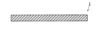
- FIG. 1 is a cross-sectional view schematically showing an example of the waterproof film of the present invention.
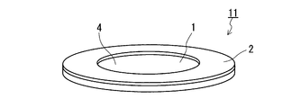
- FIG. 2A is a perspective view schematically showing an example of the waterproof member of the present invention.
- FIG. 2B is a plan view showing a surface of the waterproof member of FIG. 2A on which the support 2 is arranged, as viewed from a direction perpendicular to the main surface of the waterproof film.
- FIG. 3 is a cross-sectional view showing an example of a state in which the waterproof film of the present invention is arranged in an electronic device.
- FIG. 4 is a cross-sectional view showing another example of a state in which the waterproof film of the present invention is arranged in an electronic device.
- FIG. 5 is a plan view showing an example of the electronic device of the present invention.
- Figure 6 is a schematic view for explaining an evaluation method of the maximum velocity V max for waterproofing membrane.
- FIG. 7 is a schematic diagram for explaining a method of evaluating the sound transmission characteristic (insertion loss) of the waterproof film
- the waterproof film 1 of FIG. 1 has an insertion loss of 5.0 dB or less for a sound having a frequency of 1 kHz and a frequency of 10 kHz when the area of the sound transmission region (sound transmission region) in the waterproof film 1 is 1.3 mm 2.
- the insertion loss for the sound of is 5.0 dB or less.
- the sound transmission region in the waterproof film 1 refers to the waterproof film 1 assuming a state in which the waterproof film 1 is arranged on an object (for example, a housing of an electronic device or a member inside the housing). It means the area where sound is mainly transmitted.
- the permeation region is typically surrounded by a joint of the waterproof membrane 1 to a surface on which the waterproof membrane 1 should be placed (eg, a joint 3 described below) when viewed from a direction perpendicular to the main surface of the waterproof membrane 1. It can be defined as an area. However, when both main surfaces of the waterproof film 1 are joined to the respective surfaces to be arranged, that is, when both main surfaces of the waterproof film 1 have joints, one of them. When the area of the area surrounded by the joint is different between the main surface of the above and the other main surface, the smaller area is defined as the area of the transmission area.
- the shape of the transmission region is a circle when viewed from the direction perpendicular to the main surface of the waterproof film 1, the area of 1.3 mm 2 corresponds to the area of the transmission region in which the diameter of the circle is 1.3 mm. ..
- the sound transmission characteristics (for example, insertion loss) of the waterproof membrane have been such that the electronic device on which the waterproof membrane is placed is mainly a mobile phone, and the emphasis has been placed on ensuring the call characteristics as a telephone. Evaluation of sound with a frequency of 1 kHz, which is considered to be the median value of, has been mainly carried out.
- the sound transmission characteristics do not change so much with respect to the sound having a frequency of 1 kHz, while the sound in the high frequency range is typical. It has been found that the sound transmission characteristics for sounds having a frequency of 10 kHz tend to be significantly reduced.
- the waterproof film according to the present invention has both an insertion loss for a sound having a frequency of 1 kHz and an insertion loss for a sound having a frequency of 10 kHz at 1.3 mm 2 , which is the area of the transmission region assuming further reduction. , It is less than the predetermined value. Therefore, the waterproof film according to the present invention can cope with further reduction of the transmission region.
- the insertion loss of the waterproof film 1 (hereinafter referred to as "insertion loss IL 1.3 / 1kHz ”) for a sound having a frequency of 1 kHz when the area of the transmission region is 1.3 mm 2 is 4.0 dB or less, 3.5 dB or less, It may be 3.1 dB or less, 2.7 dB or less, and further 2.0 dB or less. Further, the insertion loss of the waterproof film 1 (hereinafter referred to as "insertion loss IL 1.3 / 10kHz ”) for sound having a frequency of 10 kHz when the area of the transmission region is 1.3 mm 2 is 4.5 dB or less and 4.0 dB.
- the waterproof film 1 may simultaneously satisfy the preferable range of the insertion loss IL 1.3 / 1kHz and the preferable range of the insertion loss IL 1.3 / 10kHz in any combination.
- the area of the transmissive region is the insertion loss of the waterproof membrane 1 with respect to the frequency 1kHz sound when the 0.79 mm 2 (hereinafter referred to as "insertion loss IL 0.79 / 1kHz"), for example 8.5dB below It may be 8.2 dB or less, 6.0 dB or less, 5.1 dB or less, 4.0 dB or less, and further 3.0 dB or less.
- the area of the transmissive region is the insertion loss of the waterproof membrane 1 with respect to sounds in the frequency 10kHz when the 0.79 mm 2 (hereinafter referred to as "insertion loss IL 0.79 / 10kHz") is, for example, less than 8.0 dB, It may be 7.5 dB or less, 7.0 dB or less, 6.5 dB or less, 6.0 dB or less, 5.6 dB or less, 5.0 dB or less, and further 4.6 dB or less.
- the waterproof film 1 may simultaneously satisfy the preferable range of the insertion loss IL 0.79 / 1kHz and the preferable range of the insertion loss IL 0.79 / 10kHz in any combination.
- the shape of the transmission region is a circle when viewed from the direction perpendicular to the main surface of the waterproof film 1, the area of 0.79 mm 2 corresponds to the area of the transmission region where the diameter of the circle is 1.0 mm. ..
- Difference between the maximum insertion loss IL 1.3 / max and the minimum insertion loss IL 1.3 / min of the waterproof film 1 for sound in the frequency range of 200 Hz or more and 10 kHz or less when the area of the transmission region is 1.3 mm 2 IL 1.3 / max- IL 1.3 / min is, for example, 5.0 dB or less, 4.2 dB or less, 4.0 dB or less, 3.0 dB or less, 2.0 dB or less, 1.5 dB or less, 1.0 dB or less, and even 0. It may be 5 dB or less.
- the difference between the maximum insertion loss IL 0.79 / max and minimum insertion loss IL 0.79 / min of waterproofing membrane 1 with respect to sounds 10kHz below the range of frequencies 200 Hz IL 0.79 / max- IL 0.79 / min is, for example, 7.0 dB or less, 6.0 dB or less, 5.6 dB or less, 5.0 dB or less, 4.0 dB or less, 3.6 dB or less, 3.0 dB or less, 2. It may be 5 dB or less, 2.0 dB or less, 1.0 dB or less, and further 0.5 dB or less.
- the waterproof film 1 having a difference of IL 1.3 / max- IL 1.3 / min and / or a difference of IL 0.79 / max- IL 0.79 / min in these ranges has a wide sound range even when the transmission region is further reduced. It has flat sound transmission characteristics over the entire range, and in this respect, it can more reliably cope with further reduction of the transmission region.
- the maximum speed V max of the out-of-plane vibration of the waterproof film 1 when transmitting sound with a frequency of 100 Hz to 10 kHz (hereinafter, simply referred to as "maximum speed V max ").
- maximum speed V max 100 ⁇ m / sec or more, 110 ⁇ m / sec or more, 120 ⁇ m / sec or more, 200 ⁇ m / sec or more, 300 ⁇ m / sec or more, 400 ⁇ m / sec or more, 500 ⁇ m / sec or more, 600 ⁇ m / sec or more, 700 ⁇ m / sec. It may be 800 ⁇ m / sec or more.
- the upper limit of the maximum speed V max is, for example, 1300 ⁇ m / sec or less.
- the sound with a frequency of 1 kHz which is a conventional evaluation standard for the waterproof film, and the sound concerned It was found that the state of vibration of the film generated during transmission has a particularly large effect, unlike the transmission of sound in the mid-low range including sound (typically, sound having a frequency of 8 kHz or less). More specifically, the larger the maximum speed V max , the more the sound transmission characteristic for the sound having a frequency of 10 kHz tends to be improved.
- the maximum speed V max of the waterproof film 1 can be measured by a laser Doppler vibrometer, which is a non-contact vibrometer.
- the air permeability of the waterproof film 1 in the thickness direction is measured in accordance with the air permeability measurement method A (Frazil type method) specified in Japanese Industrial Standards (hereinafter referred to as "JIS") L1096: 2010. In terms of degree, it is preferably less than 3.0 cm 3 / (cm 2 ⁇ sec), 2.5 cm 3 / (cm 2 ⁇ sec) or less, 2.2 cm 3 / (cm 2 ⁇ sec) or less, 2 0.0 cm 3 / (cm 2 seconds) or less, 1.8 cm 3 / (cm 2 seconds) or less, 1.6 cm 3 / (cm 2 seconds) or less, 1.0 cm 3 / (cm 2 seconds) or less , 0.8 cm 3 / (cm 2 ⁇ sec) or less, 0.5 cm 3 / (cm 2 ⁇ sec) or less, and further may be 0.3 cm 3 / (cm 2 ⁇ sec) or less.
- JIS Japanese Industrial Standards
- the maximum velocity V max of the film can be improved, whereby the permeation region can be improved. Even when the area is further reduced, the sound transmission characteristics in the high frequency range can be secured more reliably.
- a measuring jig is a resin plate having a through hole formed in the center having a cross-sectional area corresponding to the area of a desired measuring area.
- a measuring jig having a through hole having a circular cross section having a diameter of 1 mm or less and formed in the center can be used.
- the water pressure resistance of the waterproof film 1 is, for example, 80 kPa or more.
- the water pressure resistance of the waterproof film 1 may be 100 kPa or more, 150 kPa or more, 180 kPa or more, 200 kPa or more, 230 kPa or more, 250 kPa or more, and further 270 kPa or more.
- the upper limit of the water pressure resistance is not limited, and is, for example, 3000 kPa or less.
- the water pressure resistance of the waterproof film 1 can be measured as follows by using a measuring jig and conforming to the water resistance test A method (low water pressure method) or B method (high water pressure method) of JIS L1092: 2009.
- An example of a measuring jig is a stainless steel disk with a diameter of 47 mm provided with a through hole (having a circular cross section) with a diameter of 1 mm in the center. This disk has a thickness that is not deformed by the water pressure applied when measuring the water pressure resistance.
- the water pressure resistance can be measured using this measuring jig as follows.
- the waterproof film 1 to be evaluated is fixed to one surface of the measuring jig so as to cover the opening of the through hole of the measuring jig. Fixing is performed so that water does not leak from the fixed portion of the film during the measurement of water pressure resistance.
- a double-sided adhesive tape having a water passage port having a shape matching the shape of the opening punched in the center can be used.
- the double-sided adhesive tape may be arranged between the measuring jig and the waterproof film 1 so that the circumference of the water passage and the circumference of the opening coincide with each other.
- the measuring jig to which the waterproof film 1 is fixed is set in the test device so that the surface opposite to the fixed surface of the waterproof film 1 is the water pressure application surface at the time of measurement, and the water resistance of JIS L1092: 2009 is set.
- Test The water resistance is measured according to method A (low water pressure method) or method B (high water pressure method). However, the water pressure resistance is measured based on the water pressure when water comes out from one place on the film surface of the waterproof film 1.
- the measured water pressure resistance can be the water pressure resistance of the waterproof film 1.
- an apparatus having the same configuration as the water resistance test apparatus exemplified in JIS L1092: 2009 and having a test piece mounting structure in which the above-mentioned measuring jig can be set can be used.
- the surface density of the waterproof film 1 is, for example, 1 to 30 g / m 2 .
- the upper limit of the surface density may be 20 g / m 2 or less, 15 g / m 2 or less, 10 g / m 2 or less, and further 5 g / m 2 or less.
- the lower limit of the surface density may be 2 g / m 2 or more.
- the surface density can be calculated by dividing the mass of the waterproof film 1 by the area (area of the main surface).
- the thickness of the waterproof film 1 is, for example, 3 to 30 ⁇ m.
- the upper limit of the thickness may be 25 ⁇ m or less, 20 ⁇ m or less, and further may be 15 ⁇ m or less.
- the lower limit of the thickness may be 5 ⁇ m or more.
- the waterproof film 1 may satisfy at least two types of ranges selected from the above-mentioned range of air permeability in the thickness direction, range of water pressure resistance, range of surface density, and range of thickness in any combination. ..
- the waterproof film 1 includes, for example, polyester such as polyethylene terephthalate (PET), polycarbonate, polyethylene, polyimide, polytetrafluoroethylene (PTFE), polyvinylidene fluoride (PVDF), tetrafluoroethylene-ethylene copolymer (ETFE), and polyurethane. , Consists of resins such as silicone.
- PET polyethylene terephthalate
- PTFE polycarbonate
- PVDF polyvinylidene fluoride
- ETFE tetrafluoroethylene-ethylene copolymer
- polyurethane Consists of resins such as silicone.
- the resin constituting the waterproof film 1 is not limited to the above example.
- PTFE is suitable.
- the film composed of PTFE (PTFE film) has a good balance between mass and strength.
- the waterproof film 1 may be a porous film.
- the PTFE membrane may be a paste extruded product containing PTFE particles or a porous membrane formed by stretching a cast membrane (PTFE porous membrane).
- the waterproof film 1 may be a microporous film or a non-porous film.
- the microporous membrane and the non-porous membrane can have high water pressure resistance and the degree of deformation due to water pressure is small.
- the microporous membrane may be a PTFE microporous membrane composed of PTFE.
- the non-porous membrane may be a PTFE non-porous membrane composed of PTFE.
- the air permeability in the thickness direction of the microporous membrane is based on the air permeability (garley air permeability) obtained in accordance with the air permeability measurement method B (garley type method) specified in JIS L1096: 2010. Represented, it means a film of 10 seconds / 100 mL or more and 10,000 seconds / 100 mL or less.
- the lower limit of the Garley air permeability in the microporous membrane may be 20 seconds / 100 mL or more, 30 seconds / 100 mL or more, 40 seconds / 100 mL or more, 50 seconds / 100 mL or more, and further 70 seconds / 100 mL or more.
- the upper limit of the Garley air permeability in the microporous membrane may be 5000 seconds / 100 mL or less, 1000 seconds / 100 mL or less, and further 300 seconds / 100 mL or less.
- the non-porous membrane means a membrane in which the air permeability in the thickness direction exceeds 10,000 seconds / 100 mL in terms of the Garley air permeability.
- the air permeability in the thickness direction of the porous membrane is usually less than 10 seconds / 100 mL in terms of the Garley air permeability.
- the Garley air permeability can be evaluated by using a measuring jig.
- An example of a measuring jig is a polycarbonate disk having a thickness of 2 mm and a diameter of 47 mm, which is provided with a through hole (having a circular cross section of 1 mm or 2 mm in diameter) in the center.
- the measurement of the Garley air permeability using this measuring jig can be carried out as follows.
- the waterproof film 1 to be evaluated is fixed to one surface of the measuring jig so as to cover the opening of the through hole of the measuring jig.
- air passes only through the opening and the effective test part of the waterproof film 1 to be evaluated (the part that overlaps the opening when viewed from the direction perpendicular to the main surface of the fixed waterproof film 1) during the measurement of the Garley air permeability.
- the fixed portion does not obstruct the passage of air in the effective test portion of the waterproof film 1.
- a double-sided adhesive tape having a vent having a shape matching the shape of the opening punched in the center can be used.
- the double-sided adhesive tape may be arranged between the measuring jig and the waterproof film 1 so that the circumference of the vent and the circumference of the opening coincide with each other.
- the measuring jig to which the waterproof film 1 is fixed is set in the Garley type breathability tester so that the fixed surface of the waterproof film 1 is on the downstream side of the air flow at the time of measurement, and 100 mL of air is discharged to the waterproof film 1.
- the time t1 to pass through is measured.
- the obtained converted value t can be used as the garley air permeability of the waterproof film 1.
- the area of the effective test portion of the waterproof film 1 is the area of the cross section of the through hole.
- Condensation may occur inside the housing when the temperature of the housing drops due to the use or mounting of electronic devices in water.
- the occurrence of dew condensation can be prevented by reducing the amount of water vapor that stays inside the housing.
- the waterproof film 1 is a non-porous film, for example, a PTFE non-porous film
- water vapor is prevented from entering the inside of the housing through the waterproof film 1. Therefore, by selecting the non-porous film as the waterproof film 1, the amount of water vapor staying inside the housing can be reduced, and the occurrence of dew condensation inside the housing can be prevented.
- the retention of water vapor inside the housing may be unavoidable.
- the housing is composed of a hygroscopic resin such as polybutylene terephthalate (PBT), acrylonitrile-butadiene-styrene resin (ABS), polymethylmethacrylate (PMMA), polypropylene (PP) or polycarbonate (PC).
- PBT polybutylene terephthalate
- ABS acrylonitrile-butadiene-styrene resin
- PMMA polymethylmethacrylate
- PP polypropylene
- PC polycarbonate
- the waterproof membrane 1 capable of releasing the water vapor accumulated inside the housing to the outside.
- An example of a selectable waterproof membrane 1 is a porous membrane or a microporous membrane, such as a PTFE porous membrane or a PTFE microporous membrane.
- the waterproof membrane 1 is a porous membrane or a microporous membrane, the retained water vapor can be discharged to the outside by the appropriate air permeability of the waterproof membrane 1, and the occurrence of dew condensation inside the housing can be prevented.
- the waterproof film 1 is a microporous film, high waterproofness is further expected.
- the average pore size of the waterproof film 1, for example, a PTFE film may be 0.01 to 1 ⁇ m.
- the upper limit of the average pore size may be 0.85 ⁇ m or less, 0.75 ⁇ m or less, 0.5 ⁇ m or less, 0.4 ⁇ m or less, 0.3 ⁇ m or less, and further 0.2 ⁇ m or less.
- the maximum pore size of the waterproof film 1, for example, a PTFE film may be 0.01 to 3 ⁇ m.
- the upper limit of the maximum pore diameter may be 1.0 ⁇ m or less, 0.8 ⁇ m or less, 0.5 ⁇ m or less, and further 0.25 ⁇ m or less.
- the ratio of the maximum pore diameter to the average pore diameter in the waterproof film 1, for example, a PTFE film, may be 1.8 or less, 1.6 or less, 1.4 or less, 1.3 or less, and further 1. It may be 2 or less.
- the film structure of the waterproof film 1 in which the ratio of the maximum pore diameter to the average pore diameter is 2 or less can have high homogeneity. Therefore, even when the transmission region is reduced, it is expected that the variation in characteristics in the state of being arranged so as to close the opening can be reduced and the maximum speed V max is further improved.
- the average pore diameter and the maximum pore diameter of the waterproof film 1 can be measured according to ASTM (American Society for Testing and Materials) F316-86.
- the porosity of the waterproof film 1, for example, the PTFE film, may be 1 to 99%.
- the upper limit of the porosity may be 90% or less, 85% or less, 80% or less, 75% or less, 70% or less, 60% or less, and further 50% or less.
- the lower limit of the porosity may be 5% or more, 10% or more, 15% or more, and further 20% or more.
- the porosity of the waterproof film 1 can be calculated by substituting the mass, thickness, area (area of the main surface) and true density of the film into the following formula.
- the true density of PTFE is 2.18 g / cm 3 .
- Formula: Porosity (%) ⁇ 1- (mass [g] / (thickness [cm] x area [cm 2 ] x true density [g / cm 3 ])) ⁇ x 100
- the specific surface area of the waterproof film 1, for example, a PTFE film may be 6 m 2 / g or more, 10 m 2 / g or more, 30 m 2 / g or more, 50 m 2 / g or more, and further 75 m 2 / g or more. There may be.
- the upper limit of the specific surface area is, for example, 200 m 2 / g or less.
- the film structure of the waterproof film 1 having a specific surface area of 8 m 2 / g or more may have a film structure in which fine pores are uniformly distributed throughout. Therefore, further improvement of the maximum velocity V max is expected.
- the specific surface area of the waterproof film 1 can be measured according to ASTM F316-86.
- the membrane 1 When the waterproof membrane 1 is a PTFE porous membrane or a PTFE microporous membrane, the membrane 1 can be composed of innumerable PTFE fine fibers (fibrils).
- the film 1 may have an aggregated portion (node) of PTFE in which a plurality of fibrils are connected. Fibrils and nodes are typically formed by stretching a PTFE sheet, which is an aggregate of PTFE.
- the average fibril diameter of the waterproof film 1 may be, for example, 0.2 ⁇ m or less, 0.16 ⁇ m or less, 0.1 ⁇ m or less, and further 0.075 ⁇ m or less. The lower limit of the average fibril diameter is, for example, 0.02 ⁇ m or more.
- the average inter-node distance in the waterproof film 1 may be, for example, 10 ⁇ m or less, 7.5 ⁇ m or less, 5 ⁇ m or less, 2.5 ⁇ m or less, and further 1.5 ⁇ m or less.
- the lower limit of the average inter-node distance is, for example, 0.1 ⁇ m or more.
- the average fibril diameter and the average inter-node distance can be evaluated by analyzing a magnified observation image of the surface and / or cross section of the waterproof film 1 obtained by using a scanning electron microscope (SEM) or the like. The average value of the measured values evaluated at at least 10 measurement points is defined as the average fibril diameter and the average inter-node distance.
- the waterproof film 1 may be a single-layer film or a laminated body of two or more films.
- the waterproof film 1 may be composed of a single-layer PTFE film or may be a laminate of two or more PTFE films.
- the waterproof film 1 may be a colored film.
- the waterproof film 1 may be colored, for example, gray or black.
- the gray or black waterproof film 1 can be formed, for example, by mixing a gray or black colorant with a material constituting the film.
- the black colorant is, for example, carbon black.
- the color in the range of 1 to 4 is defined as "black” and the color in the range of 5 to 8 is defined as “gray” in accordance with the "achromatic lightness NV" defined in JIS Z8721: 1993. be able to.
- the waterproof film 1 may be water-repellent, oil-repellent, or liquid-repellent.
- the liquid-repellent treatment is a treatment that imparts both water-repellent and oil-repellent properties to the waterproof film 1.
- the surface of the waterproof film 1, particularly the waterproof film 1 including a PTFE film may be subjected to a physical treatment such as a sputtering treatment or a chemical treatment such as a sodium treatment. By these treatments, for example, the adhesiveness and adhesiveness on the treated surface can be enhanced.
- the shape of the waterproof film 1 is a polygon including, for example, a circle (including a substantially circle), an ellipse (including a substantially ellipse), a square, and a rectangle when viewed from a direction perpendicular to the main surface of the waterproof film 1.
- the corners of the polygon may be rounded.
- the shape of the waterproof film 1 is not limited to the above example.
- the waterproof film 1 can be distributed in a shape that is actually used, or can be distributed as a wound body of a strip-shaped film.
- the waterproof film 1 may be distributed as a single leaf having one or more arranged on the base film.
- the surface of the base film on which the waterproof film 1 is arranged may be an adhesive surface.
- the waterproof film 1 which is a wound body is used, for example, after being punched into a predetermined shape.
- the waterproof film 1 includes, for example, a housing in which a voice conversion unit that converts an electric signal and sound is housed and is provided with an opening (external sound transmission port) for transmitting sound between the voice conversion unit and the outside.
- the electronic device to be provided can be used by being attached to a housing and / or a member inside the housing so as to prevent water from entering from the outside to the inside of the housing through the opening.
- the waterproof film 1 is typically arranged in the sound transmission path between the opening and the voice conversion unit corresponding to the opening.
- the waterproof film 1 may be attached so as to close the opening.
- the opening is located between the voice conversion unit and the outside of the housing.
- the member inside the housing is, for example, a voice conversion unit.
- the waterproof film 1 may be attached so as to block the sound transmission port of the voice conversion unit.
- the mode of arrangement of the waterproof film 1 is not limited to the above example, and the member inside the housing in which the waterproof film 1 can be arranged is not limited to the above example.
- the arrangement of the waterproof film 1 allows sound to be transmitted between the audio conversion unit and the outside through the opening, and from the inside and / or the outside to the audio conversion unit of the housing through the opening. It can prevent the intrusion of water.
- the use of the waterproof film 1 is not limited to this example.
- the voice converter is typically an electroacoustic converter having the functions of a microphone, a speaker, and both a microphone and a speaker.
- the waterproof film 1 which is a PTFE porous film is obtained from, for example, an unfired PTFE sheet obtained by molding an admixture of unfired PTFE powder and a liquid lubricant into a sheet by a method such as extrusion and / or rolling. It can be formed by removing the liquid lubricant and making the PTFE sheet porous by stretching.
- the stretching may be a multi-stage stretching in which the stretching of the PTFE sheet in the MD direction (longitudinal direction) and the stretching in the TD direction (width direction) are combined.
- the sheet After forming an unfired PTFE sheet, the sheet may be treated in an atmosphere equal to or higher than the melting point of PTFE to fire the PTFE.
- a fired PTFE porous film is obtained. Be done.
- the treatment includes stretching for porosity.
- the liquid lubricant is not limited as long as it can wet the surface of the PTFE particles and can be removed later, and is, for example, a hydrocarbon oil such as naphtha, white oil, or liquid paraffin.
- "firing" means that the molded article of PTFE is treated in an atmosphere of 327 ° C. or higher, which is the melting point of PTFE.
- the waterproof film 1 which is a PTFE microporous film removes the liquid lubricant from the unfired PTFE sheet obtained for forming the PTFE porous film, and removes the liquid lubricant in a predetermined in-plane direction (typically, the MD direction). ), Then the sheet is stretched in another in-plane direction (typically in the TD direction) for microporous formation.
- the waterproof film 1 which is a PTFE non-porous film can be formed by rolling a PTFE sheet formed by an arbitrary method such as a casting method or a skive method.
- FIGS. 2A and 2B An example of the waterproof member of the present invention is shown in FIGS. 2A and 2B.
- the waterproof member 11 shown in FIGS. 2A and 2B includes a waterproof film 1 and a support 2 joined to the waterproof film 1.
- FIG. 2B shows the surface of the waterproof member 11 of FIG. 2A on the side where the support 2 is arranged, as viewed from the direction perpendicular to the main surface of the waterproof film 1.
- the waterproof film 1 is reinforced by joining the supports 2, and the handleability as the waterproof member 11 is improved.
- the support 2 can be attached to a portion where the waterproof film 1 is arranged, such as the inner surface of the housing or the surface of the voice conversion unit.
- the shape of the waterproof film 1 is a circle when viewed from the direction perpendicular to the main surface of the film 1.
- the support 2 has a shape corresponding to the shape of the peripheral edge of the waterproof film 1 when viewed from a direction perpendicular to the main surface of the waterproof film 1.
- the shape of the support 2 is a ring shape.
- the support 2 is joined to the peripheral edge of the waterproof film 1. According to this embodiment, the waterproof member 11 can be miniaturized while securing the area of the transmission region of the waterproof film 1 as much as possible.
- the transmission region (sound transmission region) of the waterproof member 11 is defined as a region surrounded by the joint portion 3 of the waterproof film 1 with the support 2 when viewed from a direction perpendicular to the main surface of the waterproof film 1.
- area 4 may also be 1.3 mm 2 or less, and further may be 0.79 mm 2 or less.
- the waterproof member 11 provided with the waterproof film 1 may have good sound transmission characteristics for high-pitched sound, for example, 10 kHz sound, even when the area of the transmission region 4 is within these ranges. In other words, the waterproof member 11 can cope with further reduction of the transmission region 4.
- the waterproof member 11 shown in FIGS. 2A and 2B includes one support 2, and the one support 2 is joined to one main surface of the waterproof film 1.
- the waterproof member 11 may include two or more supports 2, and the supports 2 may be joined to both main surfaces of the waterproof film 1. When the area of the transmission region 4 is different between both main surfaces, the smaller area can be used as the area of the transmission region 4 of the waterproof member 11.
- the waterproof member 11 can have each of the characteristics that the waterproof film 1 can have as described above in the description of the waterproof film 1.
- the material constituting the support 2 is, for example, a resin, a metal, or a composite material thereof.
- the resin is, for example, a polyolefin such as polyethylene or polypropylene; a polyester such as PET; a polycarbonate; a polyimide or a composite material thereof.
- the metal is a metal having excellent corrosion resistance, such as stainless steel and aluminum.
- the support 2 may be made of a resin foam.
- the support 2 may be a double-sided adhesive tape.
- the waterproof film 1 and the waterproof member 11 can be more reliably fixed to the surface to be arranged, which is brought about by the waterproof film 1 and the waterproof member 11. It is possible to further improve the waterproofness.
- a known double-sided adhesive tape can be used as the double-sided adhesive tape that can form the support 2.
- the base material of the double-sided adhesive tape is, for example, a resin film, a non-woven fabric, or a foam.
- the resin that can be used as the base material is not limited, and is, for example, polyester such as PET; polyolefin such as polyethylene; polyimide.
- Various adhesives such as acrylic adhesives and silicone adhesives can be used for the adhesive layer of the double-sided adhesive tape. It is preferable to use an acrylic pressure-sensitive adhesive for the pressure-sensitive adhesive layer because the bonding force to the waterproof film 1 and / or the surface to be arranged can be improved.
- the double-sided adhesive tape may be a heat-adhesive tape.
- the double-sided adhesive tape may be a base-less double-sided adhesive tape having no base material.
- the thickness of the support 2 is, for example, 5 to 500 ⁇ m, and may be 25 to 200 ⁇ m. Further, the width of the support 2 having a shape corresponding to the shape of the peripheral portion of the waterproof film 1 may be about 0.5 to 2 mm, paying attention to the function as an attachment margin.
- the support 2 which is a double-sided adhesive tape
- the support 2 and the waterproof film 1 may be bonded by the adhesive layer.
- the method of joining the waterproof film 1 and the support 2 is not limited to these examples.
- the waterproof member 11 includes, for example, a housing in which a voice conversion unit that converts an electric signal and sound is housed and is provided with an opening (external sound transmission port) for transmitting sound between the voice conversion unit and the outside.
- the electronic device to be provided can be attached to the housing and / or a member inside the housing so as to prevent water from entering through the opening from the outside to the inside of the housing.
- the waterproof member 11 is typically arranged in a sound transmission path between the opening and the voice conversion unit corresponding to the opening.
- the waterproof member 11 may be attached so as to close the opening.
- the opening is located between the voice conversion unit and the outside of the housing.
- the member inside the housing is, for example, a voice conversion unit.
- the waterproof member 11 may be attached so as to block the sound transmission port of the voice conversion unit.
- the mode of arrangement of the waterproof member 11 is not limited to the above example, and the member inside the housing in which the waterproof member 11 can be arranged is not limited to the above example.
- the support 2 is a double-sided adhesive tape
- the adhesive layer of the support 2 may be used to fix the member 11 to the surface on which the waterproof member 11 should be arranged.
- the arrangement of the waterproof member 11 allows sound to be transmitted between the sound conversion unit and the outside through the opening, and from the inside and / or the outside to the sound conversion part of the housing through the opening. It can prevent the intrusion of water.
- the use of the waterproof member 11 is not limited to this example.
- FIG. 3 shows an example of a state in which the waterproof film 1 is arranged on the electronic device.
- the waterproof film 1 is arranged inside the housing 51 of the electronic device.
- the housing 51 houses an electroacoustic converter 53 that is a voice conversion unit, and has an opening (external sound passage) 52 that transmits sound between the electroacoustic converter 53 and the outside of the housing 51. It is provided.
- the electroacoustic converter 53 has a sound passage port 54 on one surface 56 thereof.
- the opening 52 and the sound passage port 54 are in a positional relationship in which sound can be transmitted between the outside of the housing 51 and the electroacoustic converter 53, and in the example shown in FIG.
- the electroacoustic converter 53 is typically a microphone that converts sound transmitted from the sound transmission port 54 into an electric signal, a speaker that converts an electric signal into sound and outputs it from the sound transmission port 54, or a microphone and a speaker. It is a converter that has both functions.
- the electroacoustic transducer 53 may be configured by a micromechanical system (MEMS).
- MEMS micromechanical system
- the waterproof film 1 is arranged in a sound transmission path between the opening 52 of the housing 51 and the sound transmission port 54 of the electroacoustic converter 53.
- the waterproof film 1 is joined to the inner surface 55 of the housing 51 so as to cover the opening 52 via the support 2 (2B) which is a double-sided adhesive tape. Further, the waterproof film 1 is joined to the surface 56 of the electroacoustic converter 53 via a support 2 (2A) which is a double-sided adhesive tape so as to cover the sound passage port 54.
- the laminated body of the waterproof film 1 and the supports 2A and 2B is also a waterproof member 11.
- the waterproof film 1 prevents the ingress of water while allowing the transmission of sound.
- the arrangement of the waterproof film 1 enables sound to be transmitted between the electroacoustic transducer 53 and the outside of the housing 51 through the opening 52, while the housing 51 is connected through the opening 52. It is possible to prevent water from entering the inside and the electroacoustic transducer 53.
- FIG. 4 shows another example of the state in which the waterproof film 1 is arranged in the electronic device.
- the example shown in FIG. 4 is the same as the example shown in FIG. 3 except for the following points.
- the circuit board 57 on which the sound passage 58 is formed is housed inside the housing 51, and the electroacoustic converter 53 is fixed to one surface 59 of the circuit board 57 by a socket 61.
- the opening 52, the sound passage port 58, and the sound passage port 54 are in a positional relationship in which sound can be transmitted between the outside of the housing 51 and the electroacoustic converter 53.
- the housing 51 Seen from the direction perpendicular to the inner surface 55, they overlap each other as a whole.
- the waterproof film 1 is joined to the one surface 59 of the circuit board 57 so as to cover the sound passage port 58 via the support 2 (2B) which is a double-sided adhesive tape. Further, the waterproof film 1 is joined to the surface 56 of the electroacoustic converter 53 via a support 2 (2A) which is a double-sided adhesive tape so as to cover the sound passage port 54.
- the waterproof film 1 is fixed to the circuit board 57 in a state of being inserted into the opening of the socket 61, which is a member of the circuit board 57. Further, the waterproof member 11 provided with the waterproof film 1 and the support 2 (2A, 2B) is fixed to the circuit board 57 in a state of being inserted into the opening of the socket 61 which is a member of the circuit board 57.
- the waterproof film 1 and / or the waterproof member 11 may be fixed to the circuit board 57 in a state of being inserted into the sound passage port 58 of the circuit board 57.
- a seal 60 is arranged between the circuit board 57 and the housing 51.
- the seal 60 has, for example, the same configuration as the support 2.
- the arrangement of the waterproof film 1 enables sound to be transmitted between the electroacoustic transducer 53 and the outside of the housing 51 through the opening 52, while the housing 51 is connected through the opening 52. It is possible to prevent water from entering the inside and the electroacoustic transducer 53.
- the state of arrangement of the waterproof member with respect to the electronic device is not limited to those shown in the above examples.
- FIG. 5 An example of the electronic device of the present invention is shown in FIG.
- the electronic device shown in FIG. 5 is a smartphone 62. Inside the housing 51 of the smartphone 62, a voice conversion unit that converts an electric signal and sound is arranged.
- the housing 51 is provided with an opening 52 (52A) and an opening 52 (52B), which are external sound passage ports.
- the smartphone 62 includes a waterproof film 1 and / or a waterproof member 11.
- the state of arrangement of the waterproof film 1 and / or the waterproof member 11 on the smartphone 62 is as shown in FIG. 3 or FIG. 4, for example.
- the waterproof film 1 is arranged in the sound transmission path between the opening 52A and / or the opening 52B and the voice conversion unit corresponding to each of the openings 52A and 52B, whereby the opening 52A is arranged. And / or to the inside and / or each audio conversion unit of the housing 51 through the opening 52A and / or the opening 52B while enabling sound transmission between each audio conversion unit and the outside through the opening 52B. It is not limited as long as the intrusion of water from the outside is prevented.
- the electronic device provided with the waterproof film 1 and / or the waterproof member 11 is not limited to the smartphone 62.
- Electronic devices include, for example, wearable devices such as smart watches and wristbands; various cameras including action cameras and security cameras; communication devices such as mobile phones and smartphones; virtual reality (VR) devices; augmented reality (AR) devices; Sensor devices, etc.
- VR virtual reality
- AR augmented reality
- the waterproof film 1 and the waterproof member 11 described above have air permeability in the thickness direction
- the waterproof film 1 and the waterproof member 11 have openings for the purpose of gas flow (for example, a vent, a ventilation port, a pressure adjusting port, etc.).
- gas flow for example, a vent, a ventilation port, a pressure adjusting port, etc.
- the waterproof film 1 and the waterproof member 11 each function as a waterproof film and a waterproof member that allow gas to permeate and prevent water from entering, and by this function, the housing of the housing through the opening in the electronic device. It is possible to prevent water from entering the inside of the housing through the opening while allowing ventilation inside and outside.
- the waterproof film 1 and the waterproof member 11 may be used without being directly combined with the voice conversion unit.
- An electronic device provided with a housing provided with an opening for the purpose of gas flow is, for example, a sensor device such as a pressure sensor, a flow rate sensor, or a gas concentration sensor (O 2 sensor). Further, the electronic device may be an electronic device having a voice function such as a smartphone. In this case, the opening is typically provided in the housing separately from the external sound vent. However, the electronic device provided with a housing provided with an opening for the purpose of gas flow is not limited to the above example.
- Example 1 20 parts by weight of liquid lubricant (n-dodecane, manufactured by Japan Energy Co., Ltd.) is uniformly mixed with 100 parts by weight of PTFE fine powder (Polyflon F-104 manufactured by Daikin Industries, Ltd.), compressed into a cylinder, and then ram. It was extruded with an extruder to obtain a sheet-like molded body extending in the longitudinal direction. This sheet-shaped molded product was passed between metal rolling rolls in a state containing a liquid lubricant and rolled to a thickness of 0.2 mm.
- liquid lubricant n-dodecane, manufactured by Japan Energy Co., Ltd.
- PTFE fine powder Polyflon F-104 manufactured by Daikin Industries, Ltd.
- the liquid lubricant was removed by heating the sheet-shaped molded product to 150 ° C., and the sheet-shaped molded product was dried. Then, the sheet-shaped molded product is stretched at 300 ° C. in the longitudinal direction at a magnification of 2.5 times, stretched at 200 ° C. at a magnification of 20 times in the width direction, and then at 400 ° C., which is a temperature equal to or higher than the melting point of PTFE. It was fired to obtain a waterproof film A which is a PTFE porous film having a thickness of 15 ⁇ m.
- Example 2 A sheet-shaped molded product having a thickness of 0.2 mm (before removal of the liquid lubricant) obtained in the same manner as in Example 1 was stretched at room temperature at a magnification of 4.5 times in the width direction. Next, the stretched sheet-shaped molded product was heated to 150 ° C. to remove the liquid lubricant and dried. Then, the sheet-shaped molded product is stretched at 300 ° C. in the longitudinal direction at a magnification of 2.0 times, stretched at 100 ° C. in the width direction at a magnification of 20 times, and then at 400 ° C., which is a temperature equal to or higher than the melting point of PTFE. By firing, a waterproof film B, which is a PTFE porous film having a thickness of 6 ⁇ m, was obtained.
- the coating film was formed by immersing the polyimide substrate in a PTFE dispersion and then pulling it up. Next, the entire substrate and coating film were heated to form a cast film of PTFE. The heating was carried out in two stages: a first heating (100 ° C., 1 minute) and a subsequent second heating (390 ° C., 1 minute). The first heating proceeded with the removal of the dispersion medium contained in the coating film, and the second heating promoted the formation of a cast film based on the binding of PTFE particles contained in the coating film. After repeating the above immersion and subsequent heating twice more, the formed PTFE cast film (thickness 25 ⁇ m) was peeled off from the polyimide substrate.
- the peeled cast film was rolled in the MD direction (longitudinal direction) and further stretched in the TD direction (width direction). Rolling in the MD direction was carried out by roll rolling. The rolling magnification (area magnification) was 2.0 times, and the temperature (roll temperature) was 170 ° C. Stretching in the TD direction was carried out by a tenter stretching machine. The stretching ratio in the TD direction was 2.0 times, and the temperature (temperature of the stretching atmosphere) was 300 ° C. In this way, a waterproof film C, which is a PTFE microporous film having a film thickness of 10 ⁇ m and a surface density of 15 g / m 2 , was obtained.
- Example 4 A sheet-shaped molded product having a thickness of 0.2 mm (before removal of the liquid lubricant) obtained in the same manner as in Example 1 was stretched at room temperature at a magnification of 4.5 times in the width direction. Next, the stretched sheet-shaped molded product was heated to 150 ° C. to remove the liquid lubricant and dried. Then, the sheet-shaped molded product is stretched at 300 ° C. in the longitudinal direction at a magnification of 3.0 times, stretched at 100 ° C. in the width direction at a magnification of 20 times, and then at 400 ° C., which is a temperature equal to or higher than the melting point of PTFE. By firing, a waterproof film D, which is a PTFE porous film having a thickness of 8 ⁇ m, was obtained.
- the stretching temperature in the longitudinal direction is set to 380 ° C.
- the stretching ratio is set to 4.5 times
- the stretching temperature in the width direction is set to 330 ° C.
- the stretching ratio is set to 10 times
- the stretching ratio is set to 10 times in the width direction.
- a waterproof film E which is a PTFE porous film having a film thickness of 25 ⁇ m, was obtained in the same manner as the waterproof film A except that firing was not performed after stretching.
- the average pore diameter and the maximum pore diameter of the waterproof film were determined using an Automated perm porometer manufactured by Porous Materials Inc., which can measure in accordance with ASTM F316-86. Further, the ratio of the maximum pore diameter to the average pore diameter was calculated from the obtained average pore diameter and the maximum pore diameter.
- the specific surface area of the waterproof film was determined using a Perm-Porometer manufactured by Porous Materials Inc., which can measure according to ASTM F316-86.
- the average fibril diameter and the average inter-node distance of the waterproof film are measured in 10 measurement areas (50 ⁇ m ⁇ 50 ⁇ m ⁇ ) in a magnified observation image (magnification 1000 to 20000 times) obtained by observing the surface of the waterproof film to be evaluated by SEM. A 50 ⁇ m square) is determined, the average diameter of the fibrils existing in each measurement area, and the average distance between the nodes existing in each measurement area are calculated, and then the average between the measurement areas for each of the average diameter and the average distance. The value was calculated and calculated.
- the water pressure resistance of the waterproof film was measured according to the water resistance test A method (low water pressure method) or B method (high water pressure method) of JIS L1092: 2009 using the above-mentioned measuring jig.
- the waterproof film to be evaluated was punched into a circle having a diameter of 5.8 mm to obtain a test piece 71.
- the supports 72A and 72B (outer diameter 5.8 mm and inner diameter 1.3 mm) made of double-sided adhesive tape (Nitto Denko, No. 57120B) were placed on both main surfaces of the obtained test piece 71. Ring-shaped, 0.2 mm thick) were joined.
- the supports 72A and 72B were joined to the test piece 71 by using an adhesive layer of a double-sided adhesive tape so that the outer circumferences of the supports 72A and 72B coincided with the circumference of the test piece 71.
- the shape and area of the transmission region in the test piece 71 became a circle and 1.3 mm 2 when viewed perpendicular to the main surface of the test piece 71 by joining the supports 72A and 72B having the predetermined shape and size. ..
- a polycarbonate sheet 73 (circle with a diameter of 47 mm, thickness 1.0 mm) imitating the housing of an electronic device and a polycarbonate sheet 75 (circle with a diameter of 47 mm, thickness 1.0 mm) imitating the housing of a voice conversion unit.
- a polycarbonate sheet 73 (circle with a diameter of 47 mm, thickness 1.0 mm) imitating the housing of an electronic device
- a polycarbonate sheet 75 (circle with a diameter of 47 mm, thickness 1.0 mm) imitating the housing of a voice conversion unit.
- Sound vents 74 and 76 are provided in the centers of the polycarbonate sheets 73 and 75, respectively, and the polycarbonate sheets 73 and 75 are the main surfaces of the test piece 71. It was joined to the test piece 71 so that the centers of the sound passage ports 74 and 76 coincided with the center of the test piece 71 when viewed from the direction perpendicular to. When joining the members, a gap was not formed between both members to be joined. This point also applies to the joining of the members described below.
- each wall is composed of a 2.0 mm thick polycarbonate plate having a rectangular parallelepiped outer shape with a width of 50 mm, a depth of 60 mm, and a height of 28 mm, and the bottom wall of the housing 78.
- a test sound transmitter 82 equipped with a speaker 79 (SCC-16A manufactured by Star Micronics) was prepared.
- the upper wall 81 of the test sound transmitting device 82 is provided with a sound passage port 80 (a circle having a cross-sectional shape of 2.0 mm in diameter), and the speaker 79 is viewed from a direction perpendicular to the surface of the upper wall 81. It was placed on the inner surface so that the center of the sound passage 80 and the center of the cone, which is the output portion of the speaker 79, coincide with each other.
- a seal 77 (outer diameter 5.8 mm and inner diameter 1.3 mm) composed of double-sided adhesive tape (Nitto Denko, No. 57120B) is formed and has a thickness.
- the laminated body of the test piece 71, the supports 72A and 72B, and the polycarbonate sheets 73 and 75 was joined via the 1.3 mm diameter.
- the laminated body was joined so that the center of the test piece 71 and the center of the sound passage port 80 of the test sound generator 82 coincided with each other when viewed from a direction perpendicular to the main surface of the test piece 71. In the joined state, the distance between the surface of the speaker 79 and the test piece 71 was about 21 mm.
- a sound having a frequency of 100 Hz to 10 kHz (sound pressure level of 85 dB at the sound passage port 80) is output from the speaker 79 while raising the frequency from 100 Hz to pass through the test piece 71, and a laser Doppler vibrometer (manufactured by Polytech).
- NLV-2500 laser oscillation / receiver 83 is fixed above the sound passage port 74, the laser 84 is irradiated to the upper surface of the test piece 71 through the sound passage port 74, and the laser 84 reflected on the upper surface.
- Irradiation of the laser 84 was carried out so that the irradiation direction was perpendicular to the main surface of the test piece 71.
- the laser 84 that irradiates the test piece 71 and is reflected on the upper surface of the test piece 71 is analyzed by the attached analysis software, so that the test piece 71 is out of the plane generated by sound transmission.
- the state of vibration in the direction (including the maximum velocity V max ) can be evaluated. In this way, the maximum speed V max of the waterproof film was evaluated.
- the temperature of the measurement environment was 25 ⁇ 5 ° C., and the relative humidity was 60 ⁇ 5%.
- a laminate of the test piece 71 and the supports 72A and 72B was obtained in the same manner as in the evaluation method of the maximum velocity V max . Also, change the waterproof membrane A ⁇ E, a ring-shaped support 72A, by changing the inner diameter of 72B to 1.5mm and 1.0 mm, the area of the transmissive area in each of 1.8 mm 2 and 0.79 mm 2 The laminated body was also produced.
- a speaker unit 85 to be housed in the simulated housing was manufactured. Specifically, it is as follows. It consists of a speaker 86 (manufactured by Star Micronics, SCC-16A), which is a sound source, and a urethane sponge. It accommodates the speaker 86 and does not unnecessarily diffuse the sound from the speaker (passing the test piece 71 to be evaluated). Filling materials 87A, 87B, and 87C were prepared so as not to generate the sound input to the evaluation microphone as much as possible. The filler 87A is provided with a sound passage port 88 having a circular cross section having a diameter of 5 mm in the thickness direction thereof.
- the filler 87B is provided with a notch having a shape corresponding to the shape of the speaker 86 and a notch for accommodating the speaker cable 89 and leading the speaker cable 89 out of the speaker unit 85.
- the fillers 87C and 87B were overlapped, and the speaker 86 and the speaker cable 89 were housed in the notch of the filler 87B.
- the filler 87A was stacked so that the sound was transmitted from the speaker 86 to the outside of the speaker unit 85 via the sound transmission port 88 to obtain the speaker unit 85 (FIG. 7 (b)).
- the speaker unit produced above is inside a simulated housing 91 (made of polystyrene, outer diameter 60 mm ⁇ 50 mm ⁇ 28 mm, plate thickness 2 mm) that imitates the housing of an electronic device.
- Contained 85 is as follows.
- the prepared simulated housing 91 is composed of two portions 91A and 91B, and the portions 91A and 91B can be fitted to each other.
- a sound passage port 92 (having a circular cross section with a diameter of 2 mm) for transmitting the sound emitted from the speaker unit 85 housed inside to the outside of the simulated housing 91 and a speaker cable 89 are mounted on the simulated housing.
- a conduction hole 93 that leads out to the outside of the 91 is provided.
- the portions 91A and 91B By fitting the portions 91A and 91B to each other, a space having no opening other than the sound passage port 92 and the conduction hole 93 is formed in the simulated housing 91.
- the portion 91A and the portion 91B were fitted together, and the speaker unit 85 was housed in the simulated housing 91.
- the sound passage port 88 of the speaker unit 85 and the sound passage port 92 of the portion 91A are overlapped, and the sound is transmitted from the speaker 86 to the outside of the simulated housing 91 through both sound passage ports 88 and 92. It was to so.
- the speaker cable 89 was pulled out from the conduction hole 93 to the outside of the simulated housing 91, and the conduction hole 93 was closed with putty.
- the laminated body 94 of the test piece 71 and the supports 72A and 72B is formed with the adhesive layer of the support 72A to form the sound passage port 92 in the simulated housing 91. It was bonded to the surface 95.
- the laminated body 94 is joined so that the transmission region of the test piece 71 covers the sound passage port 92 and the support 72A does not overlap with the sound transmission port 92 when viewed from the direction perpendicular to the main surface of the test piece 71. did.
- the microphone 96 (Knowles) is provided by the adhesive layer of the support 72B so as to cover the transmission region of the test piece 71 in the laminated body of the test piece 71 and the supports 72A and 72B.
- SPU0410LR5H manufactured by Acoustics Co., Ltd. was bonded.
- the distance between the speaker 86 and the microphone 96 when the microphone 96 was joined was 22 mm.
- the speaker 86 and the microphone 96 are connected to an acoustic evaluation device (Multi-analyzer System 3560-B-030 manufactured by B & K), and the evaluation method is SSR (Solid State Response) mode (test signal 20 Hz to 20 kHz, sweep up).
- the insertion loss of the test piece 71 was evaluated.
- the insertion loss is automatically obtained from the test signal input from the acoustic evaluation device to the speaker 86 and the signal received by the microphone 96.
- the value (blank value) of the insertion loss when the test piece 71 is removed was obtained in advance.
- the blank value was ⁇ 24 dB at a frequency of 1 kHz and ⁇ 35 dB at a frequency of 10 kHz.
- the insertion loss of the test piece 71 is a value obtained by subtracting this blank value from the value measured by the acoustic evaluation device. The smaller the value of the insertion loss, the more the sound transmission characteristic of the sound output from the speaker 86 is maintained.
- the technology of the present invention can be applied to various electronic devices such as wearable devices such as smart watches; various cameras; communication devices such as mobile phones and smartphones; and sensor devices.
Landscapes
- Engineering & Computer Science (AREA)
- Signal Processing (AREA)
- Physics & Mathematics (AREA)
- Acoustics & Sound (AREA)
- Microelectronics & Electronic Packaging (AREA)
- Details Of Audible-Bandwidth Transducers (AREA)
- Telephone Set Structure (AREA)
- Casings For Electric Apparatus (AREA)
Abstract
Description
音の透過領域の面積が1.3mm2のときに、
周波数1kHzの音に対する挿入損失が5.0dB以下であり、
周波数10kHzの音に対する挿入損失が5.0dB以下である、
防水膜、
を提供する。
上記本発明の防水膜と、
前記防水膜に接合された支持体と、を備える防水部材、
を提供する。
開口が設けられた筐体と、
前記筐体の外部から内部への前記開口を介した水の侵入を防ぐように前記筐体及び/又は前記筐体の内部の部材に取り付けられた上記本発明の防水膜と、を備える電子機器、
を提供する。
本発明の防水膜の一例を図1に示す。図1の防水膜1は、防水膜1における音の透過領域(通音領域)の面積が1.3mm2のときに、周波数1kHzの音に対する挿入損失が5.0dB以下であり、かつ周波数10kHzの音に対する挿入損失が5.0dB以下である。本明細書において防水膜1における音の透過領域とは、対象物(例えば電子機器の筐体又は筐体の内部の部材)に防水膜1を配置した状態を想定したときに、防水膜1において音が主として透過する領域を意味する。透過領域は、典型的には、防水膜1の主面に垂直な方向から見て、防水膜1を配置すべき表面に対する防水膜1の接合部(例えば、後述の接合部3)により囲まれた領域として定めることができる。ただし、防水膜1の双方の主面がそれぞれの上記配置すべき表面に接合されている場合、即ち、防水膜1の双方の主面がそれぞれ接合部を有している場合であって、一方の主面と他方の主面との間で接合部により囲まれた領域の面積が異なるときは、小さい方の当該面積を透過領域の面積とする。なお、防水膜1の主面に垂直な方向から見て透過領域の形状が円である場合、1.3mm2の上記面積は、円の直径が1.3mmである透過領域の面積に対応する。
式:気孔率(%)={1-(質量[g]/(厚さ[cm]×面積[cm2]×真密度[g/cm3]))}×100
本発明の防水部材の一例を、図2A及び図2Bに示す。図2A及び図2Bに示す防水部材11は、防水膜1と、防水膜1に接合された支持体2とを備える。図2Bには、防水膜1の主面に垂直な方向から見た、図2Aの防水部材11における支持体2が配置された側の面が示されている。防水部材11では、支持体2の接合によって防水膜1が補強されるとともに、防水部材11としての取扱性が向上する。また、防水部材11では、支持体2を筐体の内面や音声変換部の表面といった防水膜1が配置される部分への取り付けしろとすることができる。
電子機器に防水膜1を配置した状態の一例を図3に示す。図3に示す例では、電子機器の筐体51の内部に防水膜1が配置されている。筐体51には、音声変換部である電気音響変換器53が収容されるとともに、電気音響変換器53と筐体51の外部との間で音を伝達する開口(外部通音口)52が設けられている。電気音響変換器53は、その1つの表面56に通音口54を有している。開口52と通音口54とは、筐体51の外部と電気音響変換器53との間で音が伝達可能な位置関係にあり、図3に示す例では、筐体51の内面55に垂直な方向から見て、各々の全体において互いに重複している。電気音響変換器53は、典型的には、通音口54から伝達された音を電気信号に変換するマイクロフォン、電気信号を音に変換して通音口54から出力するスピーカー、あるいはマイクロフォン及びスピーカーの双方の機能を有する変換器である。電気音響変換器53は、微小機械システム(MEMS)により構成されていてもよい。防水膜1は、筐体51の開口52と電気音響変換器53の通音口54との間の音の伝達経路に配置されている。より具体的には、防水膜1は、両面粘着テープである支持体2(2B)を介して開口52を覆うように筐体51の内面55に接合されている。また、防水膜1は、両面粘着テープである支持体2(2A)を介して通音口54を覆うように電気音響変換器53の表面56に接合されている。防水膜1及び支持体2A,2Bの積層体は、防水部材11でもある。防水膜1は、音の透過を許容しつつ、水の侵入を防ぐ。防水膜1の配置により図3の電子機器では、開口52を介した電気音響変換器53と筐体51の外部との間の音の伝達が可能となりながら、開口52を介した筐体51の内部及び電気音響変換器53への水の侵入を防ぐことができる。
・通音口58が形成された回路基板57が筐体51の内部に収容されており、電気音響変換器53は、回路基板57の一方の表面59に対してソケット61により固定されている。開口52、通音口58及び通音口54は、筐体51の外部と電気音響変換器53との間で音が伝達可能な位置関係にあり、図4に示す例では、筐体51の内面55に垂直な方向から見て、各々の全体において互いに重複している。
・防水膜1は、両面粘着テープである支持体2(2B)を介して通音口58を覆うように回路基板57の上記一方の表面59に接合されている。また、防水膜1は、両面粘着テープである支持体2(2A)を介して通音口54を覆うように電気音響変換器53の表面56に接合されている。
・防水膜1は、回路基板57が有する部材であるソケット61の開口の内部に挿入された状態で回路基板57に固定されている。また、防水膜1及び支持体2(2A,2B)を備える防水部材11は、回路基板57が有する部材であるソケット61の開口の内部に挿入された状態で回路基板57に固定されている。防水膜1及び/又は防水部材11は、回路基板57の通音口58に挿入された状態で回路基板57に固定されていてもよい。
・回路基板57と筐体51との間にはシール60が配置されている。シール60は、例えば、支持体2と同様の構成を有している。
本発明の電子機器の一例を図5に示す。図5に示す電子機器は、スマートフォン62である。スマートフォン62の筐体51の内部には、電気信号と音との変換を行う音声変換部が配置されている。筐体51には、外部通音口である開口52(52A)及び開口52(52B)が設けられている。スマートフォン62は、防水膜1及び/又は防水部材11を備えている。スマートフォン62における防水膜1及び/又は防水部材11の配置の状態は、例えば、図3又は図4に示すとおりである。ただし、当該配置の状態は、開口52A及び/又は開口52Bと、各々の開口52A,52Bに対応する音声変換部との間の音の伝達経路に防水膜1が配置され、これにより、開口52A及び/又は開口52Bを介した各音声変換部と外部との間の音の伝達が可能となりながら、開口52A及び/又は開口52Bを介した筐体51の内部及び/又は各音声変換部への外部からの水の侵入が防がれる限り、限定されない。
防水膜として、以下の5種類の防水膜A,B,C,D及びEを準備した。
PTFE微粉末(ダイキン工業株式会社製、ポリフロンF-104)100重量部に対し、液状潤滑剤(n-ドデカン、株式会社ジャパンエナジー製)20重量部を均一に混合し、シリンダーに圧縮した後にラム押し出し機で押出し、長手方向に延びるシート状成形体を得た。このシート状成形体を、液状潤滑剤が含まれた状態で金属製圧延ロール間に通し、厚さ0.2mmとなるように圧延した。その後、シート状成形体を150℃に加熱することにより液状潤滑剤を除去し、シート状成形体を乾燥させた。その後、シート状成形体を、300℃において長手方向に2.5倍の倍率で延伸し、200℃において幅方向に20倍の倍率で延伸した後、PTFEの融点以上の温度である400℃で焼成して、膜厚15μmのPTFE多孔質膜である防水膜Aを得た。
実施例1と同様に得た厚さ0.2mmのシート状成形体(液状潤滑剤の除去前)を常温にて幅方向に4.5倍の倍率で伸張させた。次に、伸張後のシート状成形体を150℃に加熱することにより液状潤滑剤を除去し、乾燥させた。その後、シート状成形体を、300℃において長手方向に2.0倍の倍率で延伸し、100℃において幅方向に20倍の倍率で延伸した後、PTFEの融点以上の温度である400℃で焼成して、膜厚6μmのPTFE多孔質膜である防水膜Bを得た。
PTFE粒子の分散液(PTFE粒子の濃度40質量%、PTFE粒子の平均粒径0.2μm、PTFE100質量部に対してノニオン性界面活性剤を6質量部含有)に、フッ素系界面活性剤(DIC製、メガファックF-142D)をPTFE100質量部に対して1質量部加えた。次に、フッ素系界面活性剤を加えた上記PTFE分散液の塗布膜(厚さ20μm)を、帯状のポリイミド基板(厚さ125μm)の表面に形成した。塗布膜は、ポリイミド基板をPTFE分散液に浸漬した後、引き上げることで形成した。次に、基板及び塗布膜の全体を加熱して、PTFEのキャスト膜を形成した。加熱は、第1の加熱(100℃、1分)と、その後の第2の加熱(390℃、1分)との2段階とした。第1の加熱によって、塗布膜に含まれる分散媒の除去が、第2の加熱によって、塗布膜に含まれるPTFE粒子の結着に基づくキャスト膜の形成が進行した。上記浸漬及びその後の加熱をさらに2回繰り返した後、形成されたPTFEキャスト膜(厚さ25μm)をポリイミド基板から剥離した。次に、剥離したキャスト膜をMD方向(長手方向)に圧延し、さらにTD方向(幅方向)に延伸した。MD方向の圧延は、ロール圧延により実施した。圧延の倍率(面積倍率)は2.0倍、温度(ロール温度)は170℃とした。TD方向の延伸は、テンター延伸機により実施した。TD方向の延伸の倍率は2.0倍、温度(延伸雰囲気の温度)は300℃とした。このようにして、膜厚10μm、面密度15g/m2のPTFE微多孔膜である防水膜Cを得た。
実施例1と同様に得た厚さ0.2mmのシート状成形体(液状潤滑剤の除去前)を常温にて幅方向に4.5倍の倍率で伸張させた。次に、伸張後のシート状成形体を150℃に加熱することにより液状潤滑剤を除去し、乾燥させた。その後、シート状成形体を、300℃において長手方向に3.0倍の倍率で延伸し、100℃において幅方向に20倍の倍率で延伸した後、PTFEの融点以上の温度である400℃で焼成して、膜厚8μmのPTFE多孔質膜である防水膜Dを得た。
液状潤滑剤を除去したシート状成形体に対する長手方向の延伸温度を380℃、延伸倍率を4.5倍とし、幅方向の延伸温度を330℃、延伸倍率を10倍とするとともに、幅方向の延伸を実施した後の焼成を実施しなかった以外は防水膜Aと同様にして、膜厚25μmのPTFE多孔質膜である防水膜Eを得た。
上記作製した防水膜について、以下の特性を評価した。
防水膜の気孔率は、上述の方法により求めた。
防水膜の平均孔径及び最大孔径は、ASTM F316-86に準拠した測定が可能であるPorous Materials Inc.製、Automated perm porometerを使用して求めた。また、求めた平均孔径及び最大孔径から、平均孔径に対する最大孔径の比を算出した。
防水膜の比表面積は、ASTM F316-86に準拠した測定が可能であるPorous Materials Inc.製、Perm-Porometerを使用して求めた。
防水膜の平均フィブリル径及び平均ノード間距離は、評価対象物である防水膜の表面をSEMにより観察して得た拡大観察像(倍率1000~20000倍)において10か所の測定領域(50μm×50μmの正方形)を定め、各測定領域内に存在するフィブリルの平均径、及び各測定領域内に存在するノード間の平均距離を求めた後、平均径及び平均距離の各々について測定領域間の平均値を算出して求めた。
防水膜の厚さ方向の通気性は、JIS L1096:2010に定められた通気性測定A法(フラジール形法)に準拠した上述の方法により、フラジール通気度として評価した。
防水膜の耐水圧は、上述した測定冶具を使用し、JIS L1092:2009の耐水度試験A法(低水圧法)又はB法(高水圧法)に準拠して測定した。
透過領域の面積が1.3mm2のときの周波数100Hz~10kHzの音の透過時における防水膜の面外方向への振動の最大速度Vmaxは、レーザードップラー振動計を用いて以下のように評価した。評価方法を図6を参照しながら説明する。
防水膜の挿入損失は、電子機器の筐体を模した模擬筐体を用いて以下のように評価した。


Claims (10)
- 音の透過領域の面積が1.3mm2のときに、
周波数1kHzの音に対する挿入損失が5.0dB以下であり、
周波数10kHzの音に対する挿入損失が5.0dB以下である、
防水膜。 - 前記透過領域の面積が1.3mm2のときに、周波数200Hz以上10kHz以下の範囲の音に対する最大の挿入損失IL1.3/maxと最小の挿入損失IL1.3/minとの差IL1.3/max-IL1.3/minが5.0dB以下である請求項1に記載の防水膜。
- 厚さ方向の通気度が、JIS L1096:2010に定められた通気性測定A法(フラジール形法)に準拠して測定したフラジール通気度により表して、3.0cm3/(cm2・秒)未満である請求項1又は2に記載の防水膜。
- 前記透過領域の面積が1.3mm2のときに、周波数100Hz~10kHzの音の透過時における面外方向への振動の最大速度Vmaxが100μm/秒以上である請求項1~3のいずれかに記載の防水膜。
- ポリテトラフルオロエチレン膜を含む請求項1~4のいずれかに記載の防水膜。
- 比表面積が6m2/g以上である請求項1~5のいずれかに記載の防水膜。
- 請求項1~6のいずれかに記載の防水膜と、
前記防水膜に接合された支持体と、を備える防水部材。 - 前記支持体が、前記防水膜の主面に垂直な方向から見て、前記防水膜の周縁部の形状に対応する形状を有するとともに、当該周縁部に接合されており、
前記方向から見て、前記防水膜における前記支持体との接合部により囲まれた領域として定められる前記防水部材の透過領域の面積が1.3mm2以下である請求項7に記載の防水部材。 - 開口が設けられた筐体と、
前記筐体の外部から内部への前記開口を介した水の侵入を防ぐように前記筐体及び/又は前記筐体の内部の部材に取り付けられた請求項1~6のいずれかに記載の防水膜と、を備える電子機器。 - 電気信号と音声との変換を行う音声変換部が前記筐体に収容されており、
前記開口が、前記音声変換部と前記筐体の外部との間に位置している請求項9に記載の電子機器。
Priority Applications (5)
| Application Number | Priority Date | Filing Date | Title |
|---|---|---|---|
| DE112020002143.2T DE112020002143T5 (de) | 2019-04-26 | 2020-04-24 | Wasserdichte membran, wasserdichtes element, das diese umfasst, und elektronische vorrichtung |
| US16/973,190 US11310931B2 (en) | 2019-04-26 | 2020-04-24 | Waterproof membrane, waterproof member including same, and electronic device |
| CN202410994148.5A CN118921593A (zh) | 2019-04-26 | 2020-04-24 | 具有防水膜和支承体的防水构件 |
| KR1020217038165A KR102813098B1 (ko) | 2019-04-26 | 2020-04-24 | 방수막과 이것을 구비하는 방수 부재 및 전자 기기 |
| CN202080030987.5A CN113728657B (zh) | 2019-04-26 | 2020-04-24 | 防水膜、具有该防水膜的防水构件以及电子设备 |
Applications Claiming Priority (2)
| Application Number | Priority Date | Filing Date | Title |
|---|---|---|---|
| JP2019-086644 | 2019-04-26 | ||
| JP2019086644 | 2019-04-26 |
Publications (1)
| Publication Number | Publication Date |
|---|---|
| WO2020218591A1 true WO2020218591A1 (ja) | 2020-10-29 |
Family
ID=72942087
Family Applications (1)
| Application Number | Title | Priority Date | Filing Date |
|---|---|---|---|
| PCT/JP2020/017858 Ceased WO2020218591A1 (ja) | 2019-04-26 | 2020-04-24 | 防水膜とこれを備える防水部材及び電子機器 |
Country Status (7)
| Country | Link |
|---|---|
| US (1) | US11310931B2 (ja) |
| JP (3) | JP6853400B2 (ja) |
| KR (1) | KR102813098B1 (ja) |
| CN (2) | CN118921593A (ja) |
| DE (1) | DE112020002143T5 (ja) |
| TW (1) | TW202100233A (ja) |
| WO (1) | WO2020218591A1 (ja) |
Families Citing this family (8)
| Publication number | Priority date | Publication date | Assignee | Title |
|---|---|---|---|---|
| KR102870067B1 (ko) * | 2019-12-20 | 2025-10-16 | 삼성전자주식회사 | 통기 및 방수 구조를 포함하는 웨어러블 전자 장치 |
| JP2022118886A (ja) * | 2021-02-03 | 2022-08-16 | ホシデン株式会社 | マイクロホンユニット |
| JP2022129647A (ja) * | 2021-02-25 | 2022-09-06 | カシオ計算機株式会社 | 音響装置及び電子機器 |
| US12576367B2 (en) | 2021-08-30 | 2026-03-17 | W. L. Gore & Associates, Inc. | Polyethylene membrane acoustic assembly |
| CN114554049B (zh) * | 2022-02-08 | 2024-09-06 | 歌尔科技有限公司 | 电子产品和安防系统 |
| DE102022125034A1 (de) * | 2022-09-28 | 2024-03-28 | Brückner Maschinenbau GmbH | Walzenlagerungsvorrichtung für ein Auswaschbad |
| KR20250065170A (ko) * | 2023-11-03 | 2025-05-12 | 삼성전자주식회사 | 방수 구조를 포함하는 전자 장치 |
| WO2025225328A1 (ja) * | 2024-04-26 | 2025-10-30 | 日東電工株式会社 | 防水部材 |
Citations (2)
| Publication number | Priority date | Publication date | Assignee | Title |
|---|---|---|---|---|
| JP2013115531A (ja) * | 2011-11-28 | 2013-06-10 | Nitto Denko Corp | 防水通音膜およびそれを用いた防水通音部材 |
| WO2013179631A1 (ja) * | 2012-05-31 | 2013-12-05 | 日東電工株式会社 | 音響部品用保護部材及び防水ケース |
Family Cites Families (14)
| Publication number | Priority date | Publication date | Assignee | Title |
|---|---|---|---|---|
| JP2815618B2 (ja) * | 1989-07-08 | 1998-10-27 | 日東電工株式会社 | 防水通音材 |
| JPH09169867A (ja) * | 1995-10-17 | 1997-06-30 | Asahi Chem Ind Co Ltd | 微多孔膜及びその製造方法 |
| JPH10165787A (ja) | 1996-12-11 | 1998-06-23 | Nitto Denko Corp | ポリテトラフルオロエチレン多孔質膜およびその製造方法 |
| ATE448072T1 (de) | 2001-02-21 | 2009-11-15 | New Japan Chem Co Ltd | Aufeinanderfolgend biaxial ausgerichtete, poröse polypropylenfolie und verfahren ihrer herstellung |
| JP2004083811A (ja) | 2002-08-28 | 2004-03-18 | Nitto Denko Corp | 防水通音膜 |
| JP2010165787A (ja) | 2009-01-14 | 2010-07-29 | Toshiba Corp | 半導体装置 |
| EP2475186B1 (en) * | 2009-09-04 | 2021-04-07 | Nitto Denko Corporation | Sound-transmitting film for microphone, sound-transmitting film member for microphone provided with the film, microphone, and electronic device provided with microphone |
| JP6118131B2 (ja) * | 2013-02-25 | 2017-04-19 | 日東電工株式会社 | 防水通音膜、通音部材、及び電気機器 |
| EP2914015B1 (en) * | 2013-08-30 | 2019-07-17 | Nitto Denko Corporation | Waterproof sound-transmitting film, waterproof sound-transmitting member provided with same, electronic equipment, electronic equipment case, and waterproof sound-transmitting structure |
| US10306352B2 (en) * | 2013-09-27 | 2019-05-28 | 3M Innovative Properties Company | Microphone having closed cell foam body |
| KR102458688B1 (ko) * | 2014-09-24 | 2022-10-24 | 닛토덴코 가부시키가이샤 | 고분자 필름, 방수 통음 막, 방수 통음 부재, 전자 기기, 전자 기기용 케이스, 방수 통음 구조, 방수 통기 막, 방수 통기 부재, 방수 통기 구조, 흡착용 시트, 흡착 유닛에의 작업 대상물의 흡착 방법, 세라믹 콘덴서의 제조 방법, 광학 필름, 광학 부재 및 조성물 |
| JP5940634B2 (ja) * | 2014-11-13 | 2016-06-29 | 株式会社巴川製紙所 | 音響透過性材料、並びに、当該材料を用いた建築用途を含む音響調整面構造、マイクロホン用風防、保護用グリル、音響透過性映写スクリーン及びスピーカ |
| WO2017090246A1 (ja) * | 2015-11-24 | 2017-06-01 | 日東電工株式会社 | 防水通音膜、防水通音部材及び電子機器 |
| JP6656110B2 (ja) | 2016-07-27 | 2020-03-04 | 日本ゴア株式会社 | 防水通音カバー、防水通音カバー部材および音響装置 |
-
2020
- 2020-04-24 DE DE112020002143.2T patent/DE112020002143T5/de active Pending
- 2020-04-24 CN CN202410994148.5A patent/CN118921593A/zh active Pending
- 2020-04-24 JP JP2020077793A patent/JP6853400B2/ja active Active
- 2020-04-24 US US16/973,190 patent/US11310931B2/en active Active
- 2020-04-24 KR KR1020217038165A patent/KR102813098B1/ko active Active
- 2020-04-24 CN CN202080030987.5A patent/CN113728657B/zh active Active
- 2020-04-24 WO PCT/JP2020/017858 patent/WO2020218591A1/ja not_active Ceased
- 2020-04-27 TW TW109114027A patent/TW202100233A/zh unknown
-
2021
- 2021-03-11 JP JP2021039262A patent/JP7638117B2/ja active Active
-
2025
- 2025-02-18 JP JP2025024380A patent/JP2025071172A/ja active Pending
Patent Citations (2)
| Publication number | Priority date | Publication date | Assignee | Title |
|---|---|---|---|---|
| JP2013115531A (ja) * | 2011-11-28 | 2013-06-10 | Nitto Denko Corp | 防水通音膜およびそれを用いた防水通音部材 |
| WO2013179631A1 (ja) * | 2012-05-31 | 2013-12-05 | 日東電工株式会社 | 音響部品用保護部材及び防水ケース |
Also Published As
| Publication number | Publication date |
|---|---|
| US11310931B2 (en) | 2022-04-19 |
| DE112020002143T5 (de) | 2022-02-17 |
| JP6853400B2 (ja) | 2021-03-31 |
| CN113728657A (zh) | 2021-11-30 |
| JP2020184758A (ja) | 2020-11-12 |
| JP2025071172A (ja) | 2025-05-02 |
| CN118921593A (zh) | 2024-11-08 |
| JP7638117B2 (ja) | 2025-03-03 |
| CN113728657B (zh) | 2024-08-06 |
| US20210251095A1 (en) | 2021-08-12 |
| JP2021101558A (ja) | 2021-07-08 |
| TW202100233A (zh) | 2021-01-01 |
| KR20220005508A (ko) | 2022-01-13 |
| KR102813098B1 (ko) | 2025-05-28 |
Similar Documents
| Publication | Publication Date | Title |
|---|---|---|
| JP6853400B2 (ja) | 防水膜とこれを備える防水部材及び電子機器 | |
| KR102852340B1 (ko) | 방수 부재 및 전자 기기 | |
| CN103404166B (zh) | 防水透声膜及电气产品 | |
| JP5244257B1 (ja) | 通音膜、及び通音膜を備えた電子機器 | |
| US9877094B2 (en) | Waterproof sound-permeable membrane and electronic device | |
| JP2011078089A (ja) | マイクロフォン用通音膜とそれを備えるマイクロフォン用通音膜部材、マイクロフォンならびにマイクロフォンを備える電子機器 | |
| JP2016082595A (ja) | 通音膜とそれを備える通音膜部材、ならびにマイクロフォンおよび電子機器 | |
| TW201731933A (zh) | 防水透音膜、防水透音材及電子機器 | |
| WO2016174871A1 (ja) | 高分子樹脂フィルムとこれを備える通気膜、通音膜、音響抵抗体、通気膜部材、通音膜部材、音響抵抗体部材および音響機器ならびに高分子樹脂フィルムの製造方法 | |
| JP2025084830A (ja) | 変換素子部材とこれを備える変換素子モジュール及び電子機器 | |
| JP6324109B2 (ja) | 防水通音膜の製造方法、防水通音膜及び電子機器 |
Legal Events
| Date | Code | Title | Description |
|---|---|---|---|
| 121 | Ep: the epo has been informed by wipo that ep was designated in this application |
Ref document number: 20795416 Country of ref document: EP Kind code of ref document: A1 |
|
| ENP | Entry into the national phase |
Ref document number: 20217038165 Country of ref document: KR Kind code of ref document: A |
|
| 122 | Ep: pct application non-entry in european phase |
Ref document number: 20795416 Country of ref document: EP Kind code of ref document: A1 |
|
| WWR | Wipo information: refused in national office |
Ref document number: 1020217038165 Country of ref document: KR |
|
| WWC | Wipo information: continuation of processing after refusal or withdrawal |
Ref document number: 1020217038165 Country of ref document: KR |