WO2020217707A1 - 受電装置、送電装置およびそれらの制御方法、無線電力伝送システム - Google Patents
受電装置、送電装置およびそれらの制御方法、無線電力伝送システム Download PDFInfo
- Publication number
- WO2020217707A1 WO2020217707A1 PCT/JP2020/008408 JP2020008408W WO2020217707A1 WO 2020217707 A1 WO2020217707 A1 WO 2020217707A1 JP 2020008408 W JP2020008408 W JP 2020008408W WO 2020217707 A1 WO2020217707 A1 WO 2020217707A1
- Authority
- WO
- WIPO (PCT)
- Prior art keywords
- detection
- power transmission
- power
- transmission device
- receiving device
- Prior art date
- Legal status (The legal status is an assumption and is not a legal conclusion. Google has not performed a legal analysis and makes no representation as to the accuracy of the status listed.)
- Ceased
Links
Images
Classifications
-
- H—ELECTRICITY
- H04—ELECTRIC COMMUNICATION TECHNIQUE
- H04B—TRANSMISSION
- H04B5/00—Near-field transmission systems, e.g. inductive or capacitive transmission systems
- H04B5/70—Near-field transmission systems, e.g. inductive or capacitive transmission systems specially adapted for specific purposes
- H04B5/79—Near-field transmission systems, e.g. inductive or capacitive transmission systems specially adapted for specific purposes for data transfer in combination with power transfer
-
- H—ELECTRICITY
- H02—GENERATION; CONVERSION OR DISTRIBUTION OF ELECTRIC POWER
- H02J—ELECTRIC POWER NETWORKS; CIRCUIT ARRANGEMENTS OR SYSTEMS FOR SUPPLYING OR DISTRIBUTING ELECTRIC POWER; SYSTEMS FOR STORING ELECTRIC ENERGY
- H02J50/00—Circuit arrangements or systems for wireless supply or distribution of electric power
- H02J50/60—Circuit arrangements or systems for wireless supply or distribution of electric power responsive to the presence of foreign objects, e.g. detection of living beings
-
- H—ELECTRICITY
- H02—GENERATION; CONVERSION OR DISTRIBUTION OF ELECTRIC POWER
- H02J—ELECTRIC POWER NETWORKS; CIRCUIT ARRANGEMENTS OR SYSTEMS FOR SUPPLYING OR DISTRIBUTING ELECTRIC POWER; SYSTEMS FOR STORING ELECTRIC ENERGY
- H02J50/00—Circuit arrangements or systems for wireless supply or distribution of electric power
- H02J50/10—Circuit arrangements or systems for wireless supply or distribution of electric power using inductive coupling
-
- H—ELECTRICITY
- H02—GENERATION; CONVERSION OR DISTRIBUTION OF ELECTRIC POWER
- H02J—ELECTRIC POWER NETWORKS; CIRCUIT ARRANGEMENTS OR SYSTEMS FOR SUPPLYING OR DISTRIBUTING ELECTRIC POWER; SYSTEMS FOR STORING ELECTRIC ENERGY
- H02J50/00—Circuit arrangements or systems for wireless supply or distribution of electric power
- H02J50/80—Circuit arrangements or systems for wireless supply or distribution of electric power involving the exchange of data, concerning supply or distribution of electric power, between transmitting devices and receiving devices
-
- H—ELECTRICITY
- H04—ELECTRIC COMMUNICATION TECHNIQUE
- H04B—TRANSMISSION
- H04B5/00—Near-field transmission systems, e.g. inductive or capacitive transmission systems
- H04B5/20—Near-field transmission systems, e.g. inductive or capacitive transmission systems characterised by the transmission technique; characterised by the transmission medium
- H04B5/24—Inductive coupling
- H04B5/26—Inductive coupling using coils
-
- H—ELECTRICITY
- H04—ELECTRIC COMMUNICATION TECHNIQUE
- H04B—TRANSMISSION
- H04B5/00—Near-field transmission systems, e.g. inductive or capacitive transmission systems
- H04B5/40—Near-field transmission systems, e.g. inductive or capacitive transmission systems characterised by components specially adapted for near-field transmission
- H04B5/45—Transponders
-
- H—ELECTRICITY
- H02—GENERATION; CONVERSION OR DISTRIBUTION OF ELECTRIC POWER
- H02J—ELECTRIC POWER NETWORKS; CIRCUIT ARRANGEMENTS OR SYSTEMS FOR SUPPLYING OR DISTRIBUTING ELECTRIC POWER; SYSTEMS FOR STORING ELECTRIC ENERGY
- H02J50/00—Circuit arrangements or systems for wireless supply or distribution of electric power
- H02J50/10—Circuit arrangements or systems for wireless supply or distribution of electric power using inductive coupling
- H02J50/12—Circuit arrangements or systems for wireless supply or distribution of electric power using inductive coupling of the resonant type
Definitions
- the present invention relates to a power receiving device, a power transmitting device, a control method thereof, and a wireless power transmission system.
- WPC a standardization body for non-contact charging standards
- WPC a standardization body for non-contact charging standards
- NFC a standard for short-range wireless communication
- NFC is an abbreviation for Near Field Communication.
- NFC standard sending a message to detect a device to communicate with by transmitting a carrier wave and modulating the carrier wave is called polling.
- Polling is transmitted by a device having a function called an NFC standard reader / writer.
- a device having a function of receiving polling transmitted by a reader / writer, applying load modulation to a carrier wave transmitted by the reader / writer, and responding to this polling is called an NFC tag.
- Patent Document 1 describes a configuration in which a WPC standard-compliant power receiving device having an NFC tag function transmits a response to a poll performed by a WPC standard-compliant power transmitting device having an NFC standard-compliant reader / writer function. ing.
- a WPC standard-compliant power receiving device having an NFC tag function transmits a response to a poll performed by a WPC standard-compliant power transmitting device having an NFC standard-compliant reader / writer function.
- wireless power is limited when the power transmission device performs NFC communication.
- the NFC tag may be damaged by the power transmitted from the power transmission device.
- the power transmission device has a reader / writer function as in Patent Document 1, the power transmission device detects the presence of the NFC tag by polling and limits the power to be transmitted, so that damage to the NFC tag can be avoided.
- the power receiving device has a reader / writer function
- wireless power transmission can be appropriately controlled depending on the presence or absence of the NFC tag even if the power transmitting device does not have the reader / writer function.
- no proposal has been made so far regarding the cooperative operation of the power receiving device and the power transmitting device in order to avoid damage to the NFC tag when the reader / writer function is implemented in the power receiving device.
- the present invention provides a technique related to cooperative operation of a power receiving device and a power transmitting device in a wireless power transmission system when a reader / writer is mounted on the power receiving device.
- the power receiving device has the following configuration. That is, It is a power receiving device that receives power wirelessly from the power transmission device.
- the control means is said to be the case where the power transmission device is determined not to have the detection function by the determination means and the detection state of the other device by the detection means is not determined.
- the detection by the detection means is executed, and when the detection state by the detection means is confirmed, the detection by the detection means is controlled so as not to be executed.
- the communication means transmits a signal according to the result of detection by the detection means to the power transmission device.
- the present invention when a reader / writer is mounted on the power receiving device, a suitable cooperative operation between the power receiving device and the power transmitting device in the wireless power transmission system is realized.
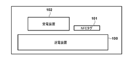
- FIG. 1A is a diagram showing an example of a system configuration according to an embodiment.
- FIG. 1B is a block diagram showing a configuration example of a power receiving device according to an embodiment.
- FIG. 2 is a block diagram showing a configuration example of a power transmission device according to an embodiment.
- FIG. 3 is a flowchart showing the operation by the control unit of the power receiving device.
- FIG. 4 is a conceptual diagram of communication regarding NFC between the first control unit and the second control unit.
- FIG. 5 is a flowchart showing the operation by the control unit of the power transmission device.
- FIG. 6 is an operation sequence diagram of the wireless charging system according to the embodiment.
- FIG. 1A is a diagram showing a configuration example of a wireless power transmission system according to an embodiment.
- a power receiving device 102 conforming to the WPC standard is mounted on the power transmitting device 100 conforming to the WPC standard.
- the power receiving device 102 receives the electric power transmitted wirelessly from the power transmitting device 100.
- the power transmission device 100 and the power reception device 102 of the present embodiment conform to the WPC standard, and further have the functions described in the WPC standard v1.2.3.
- the power transmission device 100 can detect the power reception device 102.
- the power receiving device 102 can supply the power received from the power transmitting device 100 to a load (for example, a rechargeable battery) connected to itself.
- a load for example, a rechargeable battery
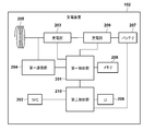
- FIG. 1B is a block diagram showing a configuration example of the power receiving device 102 according to the embodiment.
- the power receiving device 102 mounts an NFC reader / writer.
- the power transmitting device 100 and the power receiving device 102 will be described as being compliant with the WPC standard, but the present invention is not limited to this, and even if the power transmitting device 100 and the power receiving device 102 are compliant with other wireless power transmission standards. Good.
- the first control unit 201 has, for example, one or a plurality of processors and controls the entire power receiving device 102.
- An example of a processor is a CPU (Central Processing Unit) that realizes various functions by executing a predetermined program.
- the power receiving unit 203 receives the wireless power transmitted by the power transmission device 100 via the power receiving coil 205.
- the power receiving unit 203 converts the AC voltage / AC current received by the power receiving coil 205 into a DC voltage / DC current and supplies the power to the charging unit 209.
- the DC voltage / DC current output by the power receiving unit 203 is also used as a power source for driving the first control unit 201.
- the first communication unit 204 wirelessly communicates with the power transmission device 100 under the control of the first control unit 201.
- the first communication unit 204 performs load modulation, superimposes a signal on the electromagnetic wave of wireless power received via the power receiving coil 205, and transmits the signal to the power transmission device 100.
- the load modulation may be frequency modulation or amplitude modulation.
- the memory 208 stores the calculation result of the first control unit 201.
- the first communication unit 204 may perform communication conforming to the Bluetooth (registered trademark) Low Energy (hereinafter referred to as “BLE”) standard. Further, the first communication unit 204 may perform communication by a communication method such as an IEEE802.11 standard series wireless LAN (for example, Wi-Fi (registered trademark)) or ZigBee.
- NFC202 which is an example of short-range wireless communication as the second communication unit, is an NFC reader / writer and is controlled by a program implemented in the second control unit 210.
- the NFC202 is composed of a circuit conforming to the NFC standard and an NFC coil.
- the second control unit 210 that controls the NFC 202 has a function of transmitting and receiving information regarding the operation of the NFC 202 to and from the first control unit 201.
- the NFC202 can detect other devices (eg, NFC tags) that have the ability to communicate with the NFC202. Further, the second control unit 210 and the NFC 202 operate by receiving power supply from the battery 207.
- the UI 206 is a user interface of the power receiving device 102, and has a function of notifying the user of various information.
- the UI 206 will be described as being controlled by the second control unit 210, but the present invention is not limited to this.
- the UI 206 may be controlled by the first control unit 201, or may be controlled by another control unit (not shown).
- the charging unit 209 supplies the electric power supplied from the power receiving unit 203 to the battery 207 and controls the charging of the battery 207.
- FIG. 1B shows the first communication unit 204, the power receiving unit 203, and the first control unit 201 as separate bodies, some or all of them may be packaged and mounted as one component. .. Further, although the NFC 202 and the second control unit 210 are shown as separate bodies, they may be packaged and mounted as one component. That is, as long as each of the above-described configurations can realize the functions described later, there are no restrictions on the form or the like for realizing the functions.
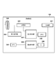
- FIG. 2 is a block diagram showing a configuration example of the power transmission device 100 according to the embodiment.
- the third control unit 301 has one or more processors and controls the entire power transmission device 100.
- An example of such a processor is a CPU that realizes various functions by executing a program.
- the power supply unit 307 uses power from a battery or an external power source (for example, a commercial power source) to supply power for operating at least the third control unit 301, the fourth control unit 309, and the power transmission unit 303.
- the power transmission unit 303 generates an alternating voltage / alternating current for transmission to the power receiving device 102 via the power transmission coil 305. Specifically, the power transmission unit 303 converts the DC voltage supplied by the power supply unit 307 into an AC voltage by a switching circuit having a half-bridge or full-bridge configuration using a FET (Field Effect Transistor).
- the power transmission unit 303 includes a gate driver that controls ON / OFF of the FET.
- the power transmission unit 303 has an ability to supply 15 watts of electric power to the charging unit 209 of the power receiving device 102 corresponding to the WPC standard.
- the third communication unit 304 wirelessly communicates with the power receiving device 102 under the control of the third control unit 301.
- the third communication unit 304 performs load modulation, superimposes the signal on the electromagnetic wave of the electric power transmitted wirelessly via the power transmission coil 305, and transmits the signal to the power receiving device 102.
- the third communication unit 304 may perform communication conforming to the Bluetooth (registered trademark) Low Energy (hereinafter referred to as "BLE") standard.
- BLE Bluetooth (registered trademark) Low Energy
- the third communication unit 304 may perform communication by a communication method such as an IEEE802.11 standard series wireless LAN (for example, Wi-Fi (registered trademark)) or ZigBee.
- the memory 308 stores the calculation result of the third control unit 301.
- NFC302 is an NFC reader / writer.
- the fourth control unit 309 controls the NFC 302. Further, the fourth control unit 309 has a function of transmitting and receiving information regarding the operation of the NFC 302 to and from the second control unit 210 of the power receiving device 102.
- the UI 306 is a user interface included in the power transmission device 100, and has a function of notifying the user of various information.
- both the power transmission device 100 and the power reception device 102 have an NFC reader / writer function.
- the NFC tag 101 is affected by wireless power transmission based on the WPC standard. Therefore, the power transmission device 100 and the power reception device 102 cooperate with each other so that the NFC tag 101 is not affected by such influence. More specifically, the power transmitting device 100 and the power receiving device 102 detect the presence of the NFC tag 101 by polling prior to wireless power transmission / reception, and determine whether or not wireless power transmission can be executed according to the detection result. To do.
- the power transmission device 100 and the power reception device 102 may interfere with each other and the NFC tag 101 may not be able to receive the poll correctly and may not be able to respond to the poll. In that case, the power transmission device 100 and the power reception device 102 cannot detect the NFC tag 101 even if it is present in the vicinity. As a result, wireless power transmission may start between the power transmitting device 100 and the power receiving device 102 even though the NFC tag 101 is present in the vicinity, and the NFC tag 101 may be damaged. In order to solve such a problem, it is important that the power transmission device 100 and the power reception device 102 operate in cooperation with each other to detect the NFC tag 101. Specifically, the power transmission device 100 and the power reception device 102 perform the following processing.
- the reader / writer is an example of a detection function for detecting an NFC tag.
- the power receiving device 102 When the power transmission device does not have a reader / writer, the power receiving device 102 operates the reader / writer to detect the NFC tag. [2] If the power transmission device has a reader / writer but does not perform polling processing, the power receiving device 102 performs polling processing. [3] When the power transmission device has a reader / writer and the polling process has already been executed, the power receiving device 102 does not perform the polling process.
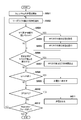
- FIG. 3 is a flowchart showing processing by the first control unit 201 of the power receiving device 102.
- FIG. 5 is a flowchart showing processing by the third control unit 301 of the power transmission device 100.
- the operation of the power receiving device 102 and the power transmitting device 100 according to the present embodiment will be described with reference to the flowcharts of FIGS. 3 and 5.
- S502 to S512 in FIG. 5 show a part of the processing executed by the power transmission device 100 during the negotiation phase (processing until it is determined as NO in S512).
- [1] is a case where the power transmission device 100 does not have a reader / writer (in FIG.
- the power transmission device 100 does not have the NFC 302 and the fourth control unit 309). In this case, the power transmission device 100 does not have the function of notifying that the S502 does not have the reader / writer function and executing the processes of S503 to S505 of FIG.
- the power transmission device 100 transmits the Digital Ping defined in the WPC standard (S501).
- the first control unit 201 is activated (S401).
- the magnitude of the power of the Digital Ping is a power sufficient for starting the first control unit 201 of the power receiving device 102 existing at least in the vicinity of the power transmission coil 305.
- the first control unit 201 activated by the Digital Ping controls the first communication unit 204 and transmits a Signal Strength Packet indicating the size of the received Digital Ping to the power transmission device 100.
- the Signal Strength Packet is a packet defined in the WPC standard, and is transmitted to the power transmission device 100 via the power receiving coil 205.
- the first control unit 201 controls the first communication unit 204 to transmit an ID Packet including its own identification information to the power transmission device 100.
- the ID Packet is a packet defined by the WPC standard, and includes version information of the WPC standard to which the first control unit 201 complies, an individual identification number of the first control unit 201, and the like. Further, the first control unit 201 controls the first communication unit 204 to transmit the Configuration Packet to the power transmission device 100.
- the Configuration Packet is a packet defined by the WPC standard, and includes information on the functions supported by the first control unit 201.
- the first control unit 201 receives an ACK from the third control unit 301 of the power transmission device 100 as a response to the Configuration Packet.
- ACK is a signal defined by the WPC standard, and indicates that the power transmission device 100 has correctly received the information contained in the Configuration Packet and has accepted the contents.
- the first control unit 201 transitions to the Negotiation phase.
- the third control unit 301 transmits ACK, it transitions to the Negotiation phase.
- negotiations regarding wireless power transmission are carried out between the power receiving device 102 and the power transmitting device 100.
- the first control unit 201 inquires the power transmission device 100 whether or not the power transmission device 100 has a reader / writer function (detection function) for detecting the NFC tag (S402).
- the General Request Packet (Capability) of the General Request Packet defined in the WPC standard and indicating the inquiry to the power transmission device can be used.
- the General Request Packet (Capability) is a packet for inquiring about the capacity information of the power transmission device.
- the packet that can be used for inquiring about the presence / absence of the NFC tag detection function is not limited to the above-mentioned packet.
- a Reserved Packet or a Proprietary Packet for which a Packet type is not defined may be defined and used as an inquiry regarding the presence or absence of the NFC tag detection function.
- the Reserved Packets and Proprietary Packets for which the Packet type is not defined may be used.
- the third control unit 301 of the power transmission device 100 notifies a packet indicating whether or not it has a reader / writer function (S502). Here, it is notified that the reader / writer function is not provided.
- the first control unit 201 that executes the determination process of S402 as described above has a function of communicating with the power transmission device 100 by using the first communication unit 204, and the power transmission device 100 has a function of detecting an NFC tag (another device). This is an example of a configuration for determining whether or not.
- a General Request Packet (Capability) and a Capability packet are used for inquiries and responses of the above-mentioned functions.
- the process proceeds to S403.
- the first control unit 201 determines that the power transmission device 100 does not have the NFC tag detection function
- the first control unit 201 inquires of the second control unit 210 whether or not the NFC tag has been detected and the result of the detection (S403). ..
- such an inquiry is referred to as a status confirmation.
- FIG. 4 is a diagram showing the contents of communication for confirming the state of NFC tag detection between the first control unit 201 and the second control unit 210.
- the response to the status confirmation inquiry consists of 2 bits. Bit0 indicates whether or not polling has been performed.
- the polling referred to here is polling executed via a coil for NFC 202 and NFC (not shown) based on a polling instruction from the first control unit 201.
- Bit0 is "0" it indicates that the second control unit 210 is not executing polling according to the instruction from the first control unit 201.
- bit0 indicates that the second control unit 210 has executed polling in response to an instruction from the first control unit 201.
- bit1 indicates whether or not the NFC tag is detected as a result of executing the above polling. If bit1 is "0”, it indicates that the second control unit 210 has not detected the NFC tag. If bit1 is "1”, it indicates that the second control unit 210 has detected the NFC tag.
- the second control unit 210 responds to the status confirmation with "00" indicating that the polling process is not executed and the NFC tag is not detected, that is, the detection status of the NFC tag is undetermined. It is assumed that the first control unit 201 is notified. If bit0 is "0", polling has not been executed, so it may be determined that the detection state of the NFC tag is undetermined regardless of the state of bit1.
- the second control unit 201 receives a second The control unit 210 is instructed to execute polling (YES in S404, NO in S405, S406).
- the first control unit 201 determines that the power transmission device 100 does not have the function of detecting the NFC tag, and the detection state of the NFC tag by the NFC 202 is undecided.
- the NFC tag is detected by using the second control unit 210 and the NFC 202.
- the first control unit 201 executes the detection of the NFC tag using the NFC 202
- the first control unit 201 communicates with the first communication unit 204 so as to limit the power transmission by the power transmission device 100 over a predetermined time.
- Request to the power transmission device 100 For example, the first control unit 201 temporarily suspends the power transmission of the Digital Ping and transmits data requesting that the polling be restarted after a predetermined time to the power transmission device 100 in order to prevent the polling from being affected by the Digital Ping (. S407).
- An End Power Transmission (EPT) packet that requests a power transmission stop, as defined in the WPC standard, can be used to request a temporary suspension of power transmission.
- the first control unit 201 transmits an EPT to which an information element indicating a temporary interruption of power transmission is added to the power transmission device 100.
- the EPT packet including the information element indicating the temporary interruption is expressed as EPT (interruption).
- the predetermined time from the interruption of the power transmission to the restart is required at least from the time when the second control unit 210 receives the polling instruction from the first control unit 201 until the polling is transmitted using the NFC 202 and the response is received. It shall be longer than the time.
- the period for temporary suspension may be set in advance in the power transmission device 100, or information for designating the predetermined time may be included in the EPT (suspension).
- the power transmission device 100 stops the power transmission of the Digital Ping for the predetermined time specified by the EPT (interruption).
- the NFC 202 starts the polling transmission and executes the polling process (S408).
- the second control unit 210 stores the detection result of the NFC tag by this polling process.
- the power receiving device 102 receives the power transmission of Digital Ping from the power transmission device 100
- the power receiving device 102 transmits a signal according to the detection result of the NFC tag to the power transmission device 100.
- the power receiving device 102 detects the NFC tag
- the power receiving device 102 transmits an EPT (NFC) packet containing an information element indicating that the NFC tag has been detected in the EPT packet to the power transmission device 100. If the NFC tag is not detected, a Signal Strength Packet or the like is transmitted.
- NFC EPT
- the transmission by the power transmission device 100 is stopped (in the execution of polling) in the detection of the NFC tag 101, but the present invention is not limited to this.
- it may be required to limit the maximum value of transmitted power to a predetermined value or less.
- the maximum value of the transmitted power is determined within a range that does not affect polling.
- the maximum value of the transmitted power may be notified from the power receiving device 102 to the power transmitting device.
- the second control unit 210 detects the NFC tag.
- the second control unit 210 holds information (referred to as NFC-related information) indicating this detection state.
- the first control unit 201 confirms the status of the second control unit 210 regarding the detection of the NFC tag, and whether or not the second control unit 210 has already executed polling (the detection status of the NFC tag is Whether it is confirmed or not) is judged. Since the second control unit 210 detected the NFC tag according to the polling instruction of the first control unit 201, it means that the polling has been executed (bit0 is "1") and the NFC tag is detected (bit1 is "1"). The indicated "11" is transmitted to the first control unit 201.
- the first control unit 201 Since the first control unit 201 is notified by the second control unit 210 that the NFC tag has been detected, it requests the power transmission device 100 to limit the power transmission of the Digital Ping (YES in S404, S405, S409, S410). ). Specifically, the power receiving device 102 transmits an EPT (NFC) packet containing an information element indicating that an NFC tag has been detected in the EPT packet to the power transmission device 100.
- the third control unit 301 of the power transmission device 100 that has received the EPT (NFC) stops the wireless power transmission (S510, S511). In the above, the power transmission by the power transmission device 100 is stopped by the EPT (NFC) packet, but the present invention is not limited to this.
- the maximum value of transmitted power may be required to limit the maximum value of transmitted power to a predetermined value or less. In that case, the maximum value of the transmitted power is determined within a range that does not damage the NFC tag. Further, in the request, the maximum value of the transmitted power may be notified from the power receiving device 102 to the power transmitting device.
- the first control unit 201 transmits an EPT to the power transmission device 100 (S411).
- the power transmission device 100 that has received the EPT stops the wireless power transmission.
- the situation in which the first control unit 201 cannot receive the response to the status confirmation from the second control unit 210 may occur, for example, when the second control unit 210 has stopped operating due to the remaining battery power. In such a case, the power receiving device 102 cannot confirm the presence or absence of the NFC tag. Therefore, in order to more reliably avoid the possibility that the NFC tag exists in the vicinity of the power transmission device 100 and is damaged by the power transmission, the first control unit 201 stops the power transmission by the power transmission device 100.
- the power transmission device 100 may be required to limit the maximum value of the power transmission to a predetermined value or less. In this way, a small amount of electric power that does not damage the NFC tag is transmitted, and the battery 207 can be charged with that electric power.
- the power receiving device 102 When the power receiving device 102 operates as described above, when the power transmitting device 100 does not have a reader / writer, the power receiving device 102 can operate the reader / writer to detect the NFC tag. Further, in the present embodiment, the second control unit 210 supplied with power from the battery 207 stores NFC-related information indicating whether or not the NFC tag detection has been performed and the result. Therefore, suitable control is realized as follows.
- NFC-related information is stored in a volatile memory (not shown) inside the first control unit 201, the first control unit 201 and the volatile memory are reset when Digital Ping is stopped due to EPT (interruption) transmission. It ends up.
- the status confirmation (S403) after restarting what should be judged based on "11" indicating that the polling process has been completed and the NFC tag has been detected is based on "00" in the reset state. Will be judged.
- the second control unit 210 which receives power from the battery 207 and is not reset by stopping the Digital Ping, stores NFC-related information.
- the second control unit 210 erases the NFC-related information held by the second control unit 210 in response to the reference by the first control unit 201 (the detection state of the NFC tag by the reader / writer). This point will be described later with reference to FIG.
- the same effect can be obtained even if the NFC-related information is stored by another configuration that is not reset by stopping Digital Ping.
- NFC-related information is stored in a non-volatile memory (not shown).
- a non-volatile memory may be mounted inside the first control unit 201 or may be connected to the first control unit 201.
- the power transmission device 100 may store NFC-related information. This is because the internal circuit of the power transmission device 100 is supplied with power by the power supply unit 307, so that the state is not reset even if the Digital Ping is stopped. In that case, the NFC-related information can be notified from the power transmitting device 100 to the power receiving device 102 in the Negotiation phase.
- This operation is an operation when the power transmission device 100 has a function of detecting the NFC tag, but the polling process is not executed.
- the process proceeds to S412.
- the power transmission device 100 has a reader / writer
- the power reception device 102 may be controlled so as not to execute polling, but in the present embodiment, the operation is switched according to the detection state of the NFC tag in the power transmission device 100. Achieve more suitable cooperative operation.
- the first control unit 201 determines that the power transmission device 100 has a reader / writer, it determines whether or not polling has been executed in the power transmission device 100 (S412).
- This determination can be realized by inquiring NFC-related information to the power transmission device 100 and receiving the response from the power transmission device 100 in the Negotiation phase. Therefore, a packet requesting information corresponding to bit0 and bit1 shown in FIG. 4 (packet inquiring about NFC-related information) is transmitted to the power transmission device 100.
- a packet for inquiring NFC-related information for example, among the packets defined in the WPC standard, a Reserved Packet or a Proprietary Packet in which the Packet type is not defined can be defined. Further, among the General Requests and Specific Requests defined in the WPC standard, the Reserved Packet and the Proprietary Packet in which the Packet type is not defined may be used.
- the third control unit 301 of the power transmission device 100 Upon receiving the inquiry for NFC-related information, the third control unit 301 of the power transmission device 100 confirms the status by inquiring the fourth control unit 309 whether or not the NFC tag has been detected and the result of the detection (S503, S504). ..
- the third control unit 301 receives the information indicating the detection state described in FIG. 4 from the fourth control unit 309, and uses the third communication unit 304 as a response to the inquiry of the NFC-related information in the packet containing this information. It is transmitted to the power transmission device 100 (S505).
- the response from the power transmission device 100 is information (“00”) indicating that polling is not executed and the NFC tag is not detected (NO in S412).
- the first control unit 201 instructs the second control unit 210 to poll (S406).
- the second control unit 210 detects the NFC tag without interfering with the Digital Ping.
- the present invention is not limited to this. If NO in S412, the first control unit 201 may execute the processing after S403.
- the first control unit 201 sends a packet indicating that it performs processing for detecting the NFC tag (that is, polling) to the power transmission device 100 following the inquiry of the NFC-related information. May be good.
- a Reserved Packet or a Proprietary Packet in which the Packet type is not defined can be defined as a packet indicating the intention of the NFC detection process.
- the Recommended Packet or the Proprietary Packet in which the Packet type is not defined may be used.
- the power transmission device 100 may not perform the polling process for a predetermined time (YES in S506, S507). By doing so, it is possible to more reliably prevent the polls transmitted by the NFC 302 of the power transmission device 100 and the NFC 202 of the power receiving device 102 from interfering with each other.
- the predetermined time is at least longer than the time required from when the second control unit 210 receives the polling instruction to when the polling is transmitted and the response is received.
- This operation is an operation when the power transmission device 100 has a reader / writer and the polling process has been executed in the power transmission device 100.
- the first control unit 201 terminates the process shown in FIG. 3, assuming that it has been confirmed that the NFC tag does not exist in the vicinity of the power transmission device 100, and wireless power transmission from the power transmission device 100 to the power reception device 102. Is executed.
- the response from the power transmission device 100 is the information (“11” in FIG. 4) indicating that polling is being executed and the NFC tag is detected.
- the first control unit 201 transmits the EPT (NFC) to the power transmission device 100 on the assumption that the NFC tag exists in the vicinity of the power transmission device 100, and ends this process (S421, S413, S410). ).
- the power transmission from the power transmission device 100 is stopped, and the wireless power transmission from the power transmission device 100 to the power reception device 102 is not executed.
- the first control unit 201 transmits EPT (NFC) in response to the detection of the NFC tag to stop the power transmission by the power transmission device 100, but the present invention is not limited to this.
- EPT NFC
- a packet requesting transmission of electric power small enough not to damage the NFC tag may be transmitted to the electric power transmission device 100, and the battery 207 may be charged with the electric power.
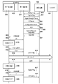
- FIG. 6 is an operation sequence diagram of the wireless charging system according to the embodiment.
- FIG. 6 illustrates an operation sequence in the case of [1] among the above three cooperative operations.
- Analog Ping is a signal of minute electric power for detecting an object existing in the vicinity of the power transmission coil 305.
- the power transmission device 100 detects the voltage value or current value of the power transmission coil 305 when the Analog Ping is transmitted, and if the voltage falls below a certain threshold value or the current value exceeds a certain threshold value, it is determined that an object exists, and the Ping phase. Transition to.
- the power transmission device 100 transmits the Digital Ping with a power larger than that of the Analog Ping (601).
- the first control unit 201 When the first control unit 201 receives the Digital Ping, it transmits the Signal Strength Packet, the ID Packet, and the Configuration Packet to the power transmission device 100 (602, 603, 604). When the power transmission device 100 transmits an ACK to the Configuration Packet and the power reception device 102 receives this (605), the power transmission device 100 and the power reception device 102 transition to the Negotiation phase. In the Negotiation phase, the first control unit 201 transmits a General Request (Capability) inquiring whether or not it has an NFC tag detection function to the power transmission device 100 (606). The first control unit 201 receives a capability from the power transmission device 100, which includes information indicating whether or not the power transmission device 100 has an NFC tag detection function (607).
- Capability General Request
- the power transmission device 100 does not have a reader / writer function (it does not have a function to detect an NFC tag).
- the first control unit 201 confirms the state of the second control unit 210 regarding the detection of the NFC tag (608).
- “00” indicating that the polling process is not executed and the NFC tag is not detected is received from the second control unit 210 (609).
- the second control unit 210 resets (erases) the detected status (NFC-related information) of the held NFC tag (610).
- the first control unit 201 issues a polling instruction to the second control unit 210 (611).
- the first control unit 201 transmits an EPT (interruption) to the power transmission device 100 (613).
- the power transmission device 100 temporarily suspends the transmission of the Digital Ping in response to the EPT (interruption)
- the second control unit 210 performs a polling process (614).
- the second control unit 210 updates and holds the detection state (NFC-related information) of the NFC tag (616).
- the first control unit 201 receives the Digital Ping from the power transmission device 100 again and restarts (617), and checks the status of the second control unit 210 again (618).
- the second control unit 210 performs polling processing and holds NFC-related information indicating that the NFC tag is detected. Therefore, “11” (FIG. 4) is the first response for status confirmation. It is transmitted to the control unit 201 (619).
- the second control unit 210 responds to the status confirmation, the NFC-related information held is cleared (erased) (620).
- the first control unit 201 Upon receiving "11" as the detection state of the NFC tag, the first control unit 201 transmits EPT (NFC) to the power transmission device 100 in order to stop the power transmission by the power transmission device 100 (621).
- EPT EPT
- the second control unit 210 clears the NFC-related information after the status confirmation response, that is, in response to the reference by the first control unit 201 (620). Specifically, the second control unit 210 transmits the detection state "11" to the first control unit 201, and then returns the detection state to "00". The reason for this is that the second control unit 210 responds (619) with information (that is, the latest NFC-related information) for polling (614) immediately after the latest polling instruction (611) of the first control unit 201. This is because it is necessary to transmit to the first control unit 201.
- the retained NFC-related information is not cleared and the status of the poll executed immediately before is retained, the following problems can be considered. For example, it is assumed that when the status confirmation (608) is received, the NFC tag is not detected by the polling performed in the past (that is, the status "10") is retained.
- the first control unit 201 does not give a polling instruction (YES in S405, NO in S409) based on the flowchart of FIG. In this case, if the NFC tag exists at the time when the status confirmation (608) is requested, there arises a problem that the NFC tag cannot be detected.
- the second control unit 210 When the second control unit 210 responds to the request for status confirmation from the first control unit 201, the held state is cleared (set to "00"), so that such a problem can be avoided. That is, the second control unit 210 holds the result of the detection executed in response to the determination by the first control unit 201 to execute the detection of the NFC tag 101 in the holding unit (for example, the non-volatile memory) as the detection state. .. Then, when the detection state held in the holding unit is referred to by the first control unit 201, the second control unit 210 operates so as to erase the detection state from the holding unit.
- the holding unit for example, the non-volatile memory
- the power receiving device 102 may be moved from the power transmission device 100 to another power transmission device (not shown). Since the first control unit 201 is stopped while the Digital Ping is stopped, the first control unit 201 cannot detect such a replacement.
- the power receiving device 102 is removed from the power transmission device 100 by the user immediately after the EPT (interruption) is transmitted, and polling is performed before the power receiving device 102 is placed in another power transmission device.
- the state related to NFC is "10" (the NFC tag is not detected as a result of polling processing).
- the power receiving device 102 is placed on the other power transmission device and an NFC tag in the vicinity of the other power transmission device is present.
- the first control unit 201 indicates the detection state (“10”) of the NFC-related information received from the second control unit 210.
- the second control unit 210 should notify the first control unit 201 of the state related to NFC as "00", but the state "10" is actually stored, and the state mismatch occurs.
- the first control unit 201 of the power receiving device 102 acquires the identification information of the power transmission device 100 and executes the detection of the NFC tag by the NFC 202, it is determined whether the acquired identification information matches before and after the execution. Confirm. If they do not match, the first control unit 201 erases the detection state held by the second control unit 210.
- the first control unit 201 Every time the first control unit 201 receives power from the Digital Ping and activates it, it inquires about the identification information of the power transmission device 100. Specifically, among the General Request Packets defined in the WPC standard, a packet inquiring about the identification information of the power transmission device is transmitted, and the identification information of the power transmission device is received. Such a packet is, for example, a General Request Packet (Power Transmitter Identification).
- the first control unit 201 compares the identification information acquired last time from the power transmission device with the identification information acquired this time, and if the identification information does not match, gives an instruction to the second control unit 210 to clear the NFC-related information. Do. In this way, the identification information of the power transmission device before and after transmitting the EPT (interruption) (before and after the detection operation of the NFC tag) can be compared, and the above-mentioned problem is solved.
- the power receiving device 102 transmits (613) the EPT (interruption), it is placed in the power transmission device 100 of the identification information “aa”, and another power transmission device (identification information “bb”) is placed during the Digital Ping interruption.
- the identification information of the power transmission device does not match before and after the EPT (interruption) (after the restart of the first control unit 201) (aa ⁇ bb)
- the state related to NFC is cleared to "00". ..
- the first control unit 201 obtains "00" as the response (619) of the status confirmation (619), and can detect the NFC tag placed on another power transmission device.
- the EPT (interruption) (613) is placed in the power transmission device of the identification information "aa” before being transmitted, and is placed in the same power transmission device (identification information "aa") even after the digital ping is interrupted. Since the identification information before and after EPT (interruption) matches, the NFC-related information is not cleared. Therefore, since the first control unit 201 receives the information information (619) related to NFC updated after polling (614), it is possible to correctly detect the presence or absence of the NFC tag placed in the power transmission device.
- the NFC reader / writer is used for NFC tag detection has been described, but the present invention is not limited to this.
- the reader / writer may be used in another application (other than the application of NFC tag detection).
- the NFC reader / writer is used in another application and the above-mentioned NFC-related information is stored, the following problems may occur. That is, when the reader / writer is used to communicate with the NFC tag in another application, the NFC-related information is updated to "11". As described above, the second control unit 210 does not clear the NFC-related information unless it transmits a response to the status confirmation. Therefore, when the power transmission device 100 and the power receiving device 102 are close to each other in this state, the first control unit 201 receives "11" from the second control unit 210 as a response of the state confirmation (S403). As a result, the first control unit 201 transmits EPT (NFC) to the power transmission device 100, and the battery 207 of the power reception device 102 can be charged even when there is no NFC tag in the vicinity of the power transmission device 100. Can not.
- EPT EPT
- the second control unit 210 stores the detection result of polling immediately after receiving the polling instruction for controlling the wireless power transmission from the first control unit 201 as an NFC-related state, and if not, the NFC. Avoid remembering related states. By doing so, even if the reader / writer is operated by another application, the second control unit 210 can solve the above-mentioned problem without updating the NFC-related information.
- the wireless power transmission method is not particularly limited.
- a magnetic field resonance method is used in which power is transmitted by coupling by resonance of the magnetic field between the resonator (resonant element) of the power transmitting device and the resonator (resonant element) of the power receiving device.
- a power transmission method using an electromagnetic induction method, an electric field resonance method, a microwave method, a laser or the like can be used.
- the power transmission device and the power receiving device may be, for example, an image input device such as an image pickup device (camera, video camera, etc.) or a scanner, or an image output device such as a printer, a copier, or a projector.
- the power transmitting device and the power receiving device may be a storage device such as a hard disk device or a memory device, or an information processing device such as a personal computer (PC) or a smartphone.
- PC personal computer
- the flow chart shown in FIG. 3 is started when the power is turned on to the first control unit 201.
- the process shown in FIG. 3 is realized by the first control unit 201 executing the program stored in the memory of the power receiving device 102.
- the process shown in FIG. 5 is realized by the third control unit 301 executing the program stored in the memory of the power transmission device 100.
- at least a part of the processes shown in the flow charts of FIGS. 3 and 5 may be realized by hardware.
- a dedicated circuit may be automatically generated on the FPGA from the program for realizing each step.
- FPGA is an abbreviation for Field Programmable GATE Array.
- the GATE Array circuit may be formed in the same manner as the FPGA and realized as hardware.
- the present invention supplies a program that realizes one or more functions of the above-described embodiment to a system or device via a network or storage medium, and one or more processors in the computer of the system or device reads and executes the program. It can also be realized by the processing to be performed. It can also be realized by a circuit (for example, ASIC) that realizes one or more functions.
Landscapes
- Engineering & Computer Science (AREA)
- Computer Networks & Wireless Communication (AREA)
- Power Engineering (AREA)
- Signal Processing (AREA)
- Near-Field Transmission Systems (AREA)
- Charge And Discharge Circuits For Batteries Or The Like (AREA)
- Transmitters (AREA)
Priority Applications (10)
| Application Number | Priority Date | Filing Date | Title |
|---|---|---|---|
| EP20796178.0A EP3961858A4 (en) | 2019-04-26 | 2020-02-28 | POWER RECEIVING DEVICE, POWER TRANSMITTING DEVICE, METHOD FOR CONTROLLING SUCH POWER RECEIVING DEVICE AND SUCH POWER TRANSMITTING DEVICE, AND WIRELESS POWER TRANSMITTING SYSTEM |
| CN202510226475.0A CN119921483A (zh) | 2019-04-26 | 2020-02-28 | 电力发送装置、电力发送装置的方法和存储介质 |
| EP23177372.2A EP4228125A1 (en) | 2019-04-26 | 2020-02-28 | Power receiving apparatus, power transmitting apparatus, control methods therefor, and wireless power transmission system |
| CN202310699791.0A CN116599549B (zh) | 2019-04-26 | 2020-02-28 | 电力发送装置、通信方法和存储介质 |
| KR1020217037345A KR102678518B1 (ko) | 2019-04-26 | 2020-02-28 | 수전 장치, 송전 장치 및 그것들의 제어 방법, 무선 전력 전송 시스템 |
| CN202510226473.1A CN119921482A (zh) | 2019-04-26 | 2020-02-28 | 电力发送装置、电力发送装置的方法和存储介质 |
| CN202080031104.2A CN113785469B (zh) | 2019-04-26 | 2020-02-28 | 电力接收装置、电力发送装置、方法和无线电力发送系统 |
| KR1020247011197A KR102693155B1 (ko) | 2019-04-26 | 2020-02-28 | 수전 장치, 송전 장치 및 그것들의 제어 방법, 무선 전력 전송 시스템 |
| US17/509,499 US12088120B2 (en) | 2019-04-26 | 2021-10-25 | Power transmitting apparatus having NFC tag detection function, control methods therefor, and storage medium |
| US18/794,761 US20240396377A1 (en) | 2019-04-26 | 2024-08-05 | Power receiving apparatus, power transmitting apparatus, control methods therefor, and storage medium |
Applications Claiming Priority (2)
| Application Number | Priority Date | Filing Date | Title |
|---|---|---|---|
| JP2019-085795 | 2019-04-26 | ||
| JP2019085795A JP7169937B2 (ja) | 2019-04-26 | 2019-04-26 | 受電装置、送電装置およびそれらの制御方法、無線電力伝送システム |
Related Child Applications (1)
| Application Number | Title | Priority Date | Filing Date |
|---|---|---|---|
| US17/509,499 Continuation US12088120B2 (en) | 2019-04-26 | 2021-10-25 | Power transmitting apparatus having NFC tag detection function, control methods therefor, and storage medium |
Publications (1)
| Publication Number | Publication Date |
|---|---|
| WO2020217707A1 true WO2020217707A1 (ja) | 2020-10-29 |
Family
ID=72942447
Family Applications (1)
| Application Number | Title | Priority Date | Filing Date |
|---|---|---|---|
| PCT/JP2020/008408 Ceased WO2020217707A1 (ja) | 2019-04-26 | 2020-02-28 | 受電装置、送電装置およびそれらの制御方法、無線電力伝送システム |
Country Status (6)
| Country | Link |
|---|---|
| US (2) | US12088120B2 (https=) |
| EP (2) | EP4228125A1 (https=) |
| JP (5) | JP7169937B2 (https=) |
| KR (2) | KR102693155B1 (https=) |
| CN (4) | CN113785469B (https=) |
| WO (1) | WO2020217707A1 (https=) |
Cited By (1)
| Publication number | Priority date | Publication date | Assignee | Title |
|---|---|---|---|---|
| WO2025047110A1 (ja) * | 2023-08-29 | 2025-03-06 | キヤノン株式会社 | 受電装置、送電装置、受電装置が実行する方法、送電装置が実行する方法、およびプログラム |
Families Citing this family (6)
| Publication number | Priority date | Publication date | Assignee | Title |
|---|---|---|---|---|
| JP7614796B2 (ja) * | 2020-11-12 | 2025-01-16 | キヤノン株式会社 | 送電装置、送電装置の制御方法、及びプログラム |
| EP4344023A4 (en) * | 2021-05-17 | 2025-07-02 | Lg Electronics Inc | METHOD AND APPARATUS FOR CONTROLLING POWER BETWEEN A PLURALITY OF DEVICES VIA OUT-OF-BAND COMMUNICATION IN A WIRELESS POWER TRANSMISSION SYSTEM |
| JP2023181742A (ja) * | 2022-06-13 | 2023-12-25 | キヤノン株式会社 | 送電装置、送電装置の制御方法、およびプログラム |
| JP2024030058A (ja) * | 2022-08-23 | 2024-03-07 | キヤノン株式会社 | 受電装置、送電装置、無線電力伝送システム、制御方法、およびプログラム |
| EP4376259A1 (en) * | 2022-11-25 | 2024-05-29 | Koninklijke Philips N.V. | Wireless power transfer |
| EP4686043A1 (en) | 2023-03-22 | 2026-01-28 | Canon Kabushiki Kaisha | Power reception device, power transmission device, method to be performed by power reception device, and storage medium |
Citations (7)
| Publication number | Priority date | Publication date | Assignee | Title |
|---|---|---|---|---|
| JP2014075858A (ja) * | 2012-10-02 | 2014-04-24 | Tokai Rika Co Ltd | ワイヤレス充電器 |
| JP2014093818A (ja) | 2012-11-01 | 2014-05-19 | Tokai Rika Co Ltd | 非接触充電器 |
| WO2017169442A1 (ja) * | 2016-03-29 | 2017-10-05 | キヤノン株式会社 | 送電装置、受電装置、制御方法、及びプログラム |
| JP2017184488A (ja) * | 2016-03-30 | 2017-10-05 | キヤノン株式会社 | 送電装置、送電装置の制御方法及びプログラム |
| JP2018133855A (ja) * | 2017-02-14 | 2018-08-23 | キヤノン株式会社 | 給電装置 |
| JP2019062595A (ja) * | 2017-09-25 | 2019-04-18 | キヤノン株式会社 | 給電機器、給電機器の制御方法、プログラム |
| JP2019085795A (ja) | 2017-11-08 | 2019-06-06 | 株式会社鴻池組 | 掘進機及びその運転方法 |
Family Cites Families (32)
| Publication number | Priority date | Publication date | Assignee | Title |
|---|---|---|---|---|
| JP5703823B2 (ja) * | 2011-02-21 | 2015-04-22 | ソニー株式会社 | 送電装置、送電方法および電力伝送システム |
| KR20120135885A (ko) * | 2011-06-07 | 2012-12-17 | 삼성전자주식회사 | 무선 전력 송수신 시스템에서의 송신기 및 수신기 간의 양방향 통신 방법 및 상기 장치들 |
| US9660478B2 (en) * | 2012-12-12 | 2017-05-23 | Qualcomm Incorporated | System and method for facilitating avoidance of wireless charging cross connection |
| EP3462570B1 (en) | 2013-07-17 | 2020-09-09 | Koninklijke Philips N.V. | Wireless inductive power transfer |
| JP6129726B2 (ja) | 2013-11-27 | 2017-05-17 | 京セラ株式会社 | 携帯端末 |
| JP6278687B2 (ja) * | 2013-12-18 | 2018-02-14 | キヤノン株式会社 | 電子機器、方法及びプログラム |
| JP6410476B2 (ja) * | 2014-05-28 | 2018-10-24 | キヤノン株式会社 | 電子機器、その制御方法、プログラム、並びに給電装置 |
| KR101711538B1 (ko) * | 2014-07-24 | 2017-03-02 | 엘지전자 주식회사 | 무선 전력 전송방법, 무선 전력 전송장치 및 무선 충전 시스템 |
| US9762085B2 (en) | 2014-10-03 | 2017-09-12 | Qualcomm Incorporated | System and method for prevention of wireless charging cross connection |
| JP2016111792A (ja) * | 2014-12-04 | 2016-06-20 | キヤノン株式会社 | 受電装置、受電装置の制御方法、プログラム |
| KR102026984B1 (ko) * | 2014-12-15 | 2019-10-07 | 주식회사 위츠 | 무선 충전 제어 방법 및 그를 이용한 무선 전력 송신 장치 및 수신 장치 |
| EP3346613B1 (en) | 2015-09-04 | 2023-03-15 | Sony Group Corporation | Information processing apparatus, information processing method, and program |
| KR102481953B1 (ko) | 2015-09-09 | 2022-12-29 | 삼성전자주식회사 | 무선 전력 송신기 및 그 제어 방법 |
| US10673487B2 (en) * | 2015-09-23 | 2020-06-02 | Intel Corporation | Method, system and apparatus to optimize A4WP wireless charging and NFC co-existence |
| KR20170053237A (ko) * | 2015-11-06 | 2017-05-16 | 엘지이노텍 주식회사 | 멀티 코일 무선 충전 방법 및 그를 위한 장치 및 시스템 |
| JP6685158B2 (ja) * | 2016-03-29 | 2020-04-22 | キヤノン株式会社 | 送電装置、受電装置、制御方法、及びプログラム |
| JP6781563B2 (ja) | 2016-03-29 | 2020-11-04 | キヤノン株式会社 | 受電装置、制御方法、及びプログラム |
| WO2017179874A1 (ko) * | 2016-04-12 | 2017-10-19 | 엘지전자 주식회사 | 무선전력 전송방법 및 무선전력 전송장치 |
| US10277058B2 (en) * | 2016-05-16 | 2019-04-30 | Qualcomm Incorporated | Near field communication (NFC) coexistance |
| KR102607032B1 (ko) * | 2016-06-16 | 2023-11-29 | 삼성전자주식회사 | 무선 전력 송신기, 무선 전력 수신기 및 그 제어 방법 |
| KR20190033480A (ko) * | 2016-07-29 | 2019-03-29 | 소니 세미컨덕터 솔루션즈 가부시키가이샤 | 수전 장치 및 전자 기기 |
| EP3493363B1 (en) * | 2016-07-29 | 2020-07-01 | Sony Semiconductor Solutions Corporation | Power-supplying device |
| JP7136694B2 (ja) * | 2016-07-29 | 2022-09-13 | ソニーセミコンダクタソリューションズ株式会社 | 給電システム |
| JP6721459B2 (ja) * | 2016-08-25 | 2020-07-15 | ラピスセミコンダクタ株式会社 | 受電装置、送電装置、給電システム及び受電方法 |
| US10530426B2 (en) * | 2016-09-23 | 2020-01-07 | Lg Electronics Inc. | Wireless power transferring method and device therefor |
| JP2018082563A (ja) | 2016-11-16 | 2018-05-24 | ローム株式会社 | 非接触給電システム及び送電装置 |
| KR20180062653A (ko) * | 2016-12-01 | 2018-06-11 | 엘지이노텍 주식회사 | 근거리 무선 통신을 이용한 무선 충전 방법 및 장치 |
| US10693296B2 (en) | 2017-05-03 | 2020-06-23 | International Business Machines Corporation | Stabilizing consumer energy demand |
| JP6968605B2 (ja) | 2017-07-14 | 2021-11-17 | シャープ株式会社 | 受電装置、受電方法、受電プログラム、非接触給電システム、および非接触給電方法 |
| KR20190054416A (ko) * | 2017-11-13 | 2019-05-22 | 삼성전기주식회사 | 무선 전력 송신 장치 |
| US10892647B2 (en) * | 2017-11-14 | 2021-01-12 | Wits Co., Ltd. | Wireless power transmitter with data communication provision |
| JP7233898B2 (ja) * | 2018-11-28 | 2023-03-07 | キヤノン株式会社 | 送電装置、送電装置の制御方法及びプログラム |
-
2019
- 2019-04-26 JP JP2019085795A patent/JP7169937B2/ja active Active
-
2020
- 2020-02-28 CN CN202080031104.2A patent/CN113785469B/zh active Active
- 2020-02-28 CN CN202510226473.1A patent/CN119921482A/zh active Pending
- 2020-02-28 KR KR1020247011197A patent/KR102693155B1/ko active Active
- 2020-02-28 CN CN202510226475.0A patent/CN119921483A/zh active Pending
- 2020-02-28 WO PCT/JP2020/008408 patent/WO2020217707A1/ja not_active Ceased
- 2020-02-28 CN CN202310699791.0A patent/CN116599549B/zh active Active
- 2020-02-28 EP EP23177372.2A patent/EP4228125A1/en active Pending
- 2020-02-28 EP EP20796178.0A patent/EP3961858A4/en active Pending
- 2020-02-28 KR KR1020217037345A patent/KR102678518B1/ko active Active
-
2021
- 2021-10-25 US US17/509,499 patent/US12088120B2/en active Active
-
2022
- 2022-10-25 JP JP2022170865A patent/JP7336581B2/ja active Active
-
2023
- 2023-07-27 JP JP2023122739A patent/JP7413594B2/ja active Active
- 2023-12-25 JP JP2023218431A patent/JP7576149B2/ja active Active
-
2024
- 2024-08-05 US US18/794,761 patent/US20240396377A1/en active Pending
- 2024-10-18 JP JP2024184274A patent/JP7755710B2/ja active Active
Patent Citations (7)
| Publication number | Priority date | Publication date | Assignee | Title |
|---|---|---|---|---|
| JP2014075858A (ja) * | 2012-10-02 | 2014-04-24 | Tokai Rika Co Ltd | ワイヤレス充電器 |
| JP2014093818A (ja) | 2012-11-01 | 2014-05-19 | Tokai Rika Co Ltd | 非接触充電器 |
| WO2017169442A1 (ja) * | 2016-03-29 | 2017-10-05 | キヤノン株式会社 | 送電装置、受電装置、制御方法、及びプログラム |
| JP2017184488A (ja) * | 2016-03-30 | 2017-10-05 | キヤノン株式会社 | 送電装置、送電装置の制御方法及びプログラム |
| JP2018133855A (ja) * | 2017-02-14 | 2018-08-23 | キヤノン株式会社 | 給電装置 |
| JP2019062595A (ja) * | 2017-09-25 | 2019-04-18 | キヤノン株式会社 | 給電機器、給電機器の制御方法、プログラム |
| JP2019085795A (ja) | 2017-11-08 | 2019-06-06 | 株式会社鴻池組 | 掘進機及びその運転方法 |
Cited By (1)
| Publication number | Priority date | Publication date | Assignee | Title |
|---|---|---|---|---|
| WO2025047110A1 (ja) * | 2023-08-29 | 2025-03-06 | キヤノン株式会社 | 受電装置、送電装置、受電装置が実行する方法、送電装置が実行する方法、およびプログラム |
Also Published As
| Publication number | Publication date |
|---|---|
| JP7336581B2 (ja) | 2023-08-31 |
| US20240396377A1 (en) | 2024-11-28 |
| KR20240049642A (ko) | 2024-04-16 |
| JP2024029107A (ja) | 2024-03-05 |
| CN116599549A (zh) | 2023-08-15 |
| US20220045553A1 (en) | 2022-02-10 |
| EP3961858A1 (en) | 2022-03-02 |
| JP7413594B2 (ja) | 2024-01-15 |
| JP7576149B2 (ja) | 2024-10-30 |
| US12088120B2 (en) | 2024-09-10 |
| KR20210151966A (ko) | 2021-12-14 |
| CN113785469B (zh) | 2025-02-25 |
| CN119921482A (zh) | 2025-05-02 |
| JP7169937B2 (ja) | 2022-11-11 |
| JP2022191489A (ja) | 2022-12-27 |
| CN113785469A (zh) | 2021-12-10 |
| CN116599549B (zh) | 2025-07-15 |
| JP2020182355A (ja) | 2020-11-05 |
| EP4228125A1 (en) | 2023-08-16 |
| JP2023134835A (ja) | 2023-09-27 |
| EP3961858A4 (en) | 2023-01-04 |
| JP7755710B2 (ja) | 2025-10-16 |
| JP2025011294A (ja) | 2025-01-23 |
| CN119921483A (zh) | 2025-05-02 |
| KR102693155B1 (ko) | 2024-08-09 |
| KR102678518B1 (ko) | 2024-06-27 |
Similar Documents
| Publication | Publication Date | Title |
|---|---|---|
| JP7755710B2 (ja) | 送電装置および通信方法、プログラム | |
| US20250015837A1 (en) | Power transmission apparatus, power reception apparatus, method, and recording medium | |
| JP7467716B2 (ja) | 送電装置、送電装置の制御方法及びプログラム | |
| EP4254816A2 (en) | Power receiving device, power receiving device control method, and program |
Legal Events
| Date | Code | Title | Description |
|---|---|---|---|
| 121 | Ep: the epo has been informed by wipo that ep was designated in this application |
Ref document number: 20796178 Country of ref document: EP Kind code of ref document: A1 |
|
| NENP | Non-entry into the national phase |
Ref country code: DE |
|
| ENP | Entry into the national phase |
Ref document number: 20217037345 Country of ref document: KR Kind code of ref document: A |
|
| ENP | Entry into the national phase |
Ref document number: 2020796178 Country of ref document: EP Effective date: 20211126 |
|
| WWG | Wipo information: grant in national office |
Ref document number: 202080031104.2 Country of ref document: CN |