WO2020217486A1 - 中継装置及び中継方法 - Google Patents
中継装置及び中継方法 Download PDFInfo
- Publication number
- WO2020217486A1 WO2020217486A1 PCT/JP2019/018043 JP2019018043W WO2020217486A1 WO 2020217486 A1 WO2020217486 A1 WO 2020217486A1 JP 2019018043 W JP2019018043 W JP 2019018043W WO 2020217486 A1 WO2020217486 A1 WO 2020217486A1
- Authority
- WO
- WIPO (PCT)
- Prior art keywords
- base station
- information
- relay device
- donor base
- neighboring cell
- Prior art date
- Legal status (The legal status is an assumption and is not a legal conclusion. Google has not performed a legal analysis and makes no representation as to the accuracy of the status listed.)
- Ceased
Links
Images







Classifications
-
- H—ELECTRICITY
- H04—ELECTRIC COMMUNICATION TECHNIQUE
- H04W—WIRELESS COMMUNICATION NETWORKS
- H04W16/00—Network planning, e.g. coverage or traffic planning tools; Network deployment, e.g. resource partitioning or cells structures
- H04W16/24—Cell structures
- H04W16/26—Cell enhancers or enhancement, e.g. for tunnels, building shadow
-
- H—ELECTRICITY
- H04—ELECTRIC COMMUNICATION TECHNIQUE
- H04W—WIRELESS COMMUNICATION NETWORKS
- H04W36/00—Hand-off or reselection arrangements
- H04W36/14—Reselecting a network or an air interface
- H04W36/142—Reselecting a network or an air interface over the same radio air interface technology
Definitions
- the present invention relates to a relay technique for relaying communication between a terminal device and a donor base station.
- LTE Long T erm E volution
- the terminal device in order to improve the coverage area of (UE U ser E quipment), in addition to the donor base station has a smaller coverage area than the donor base station Small-cell base stations are used. Small cell base station, access (AC: Ac cess Link) through a communication path connected to the terminal device.
- the small cell base station establishes communication with the donor base station, through the donor base station backhaul (BH: B ack h aul Link ) mobile operators by channel (MNO: M obile N Connect to a mobile communication network operated by etwork O perator).
- BH B ack h aul Link
- MNO M obile N Connect to a mobile communication network operated by etwork O perator.
- the base station stores the neighborhood cell information table, which is a table including the information of the neighborhood cell of the base station, in the storage unit as the information of the handover destination candidate of the terminal device (Patent Document 2).
- a neighborhood cell information table is called a Neighbor Relation Table (NRT).
- Patent No. 6025892 Japanese Unexamined Patent Publication No. 2018-148376
- the terminal device and the relay device are associated with a specific mobile communication operator, and the movement operated by this specific mobile communication operator. Connected to a mobile network.
- a plurality of mobile communication carriers are associated with one of the above relay devices (or small cell base stations) so that the relay devices can be connected to a network operated by the plurality of mobile communication carriers.
- the relay device needs to store cell information about the networks of a plurality of operators in order to hand over the terminal device, and as a result, more information on neighboring cells is stored.
- the present invention has been made in view of the above, and an object of the present invention is to more equitably store information on neighboring cells in a relay device among a plurality of businesses.
- the relay device is a relay device that relays communication between the terminal device and the donor base station, and is among the base stations associated with the identification information of a specific mobile communication carrier.
- a storage unit for storing information on the neighboring cell is provided, and an area in the storage unit for storing information on the neighboring cell is secured for each of the identification information corresponding to the established backhaul communication path.
- the relay method is a relay method implemented by a relay device that relays communication between a terminal device and a donor base station, and is associated with identification information of a specific mobile communication carrier.
- the backhaul communication path was established with the donor base station, and the information of the neighboring cells of the relay device among the cells formed by the base station was received from the base station.
- An area in the storage unit for storing the information of the neighboring cells, including storing in the storage unit based on the signal, is secured for each of the identification information corresponding to the established backhaul communication path. Will be done.
- information on neighboring cells can be more fairly stored in the relay device among a plurality of businesses.
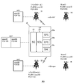
- FIG. 1 It is a conceptual diagram which shows the structure of the typical mobile communication system which concerns on one Embodiment. It is a hardware block diagram of the relay device which concerns on one Embodiment. It is a schematic diagram explaining the operation of the backhaul communication part which concerns on one Embodiment. It is a schematic diagram explaining the operation of the division
- FIG. 1 It is a conceptual diagram which shows the structure of the typical mobile communication system which concerns on one Embodiment. It is a hardware block diagram of the relay device which concerns on one Embodiment. It is a schematic diagram explaining the operation of the backhaul communication part which concerns on one Embodiment. It
- FIG. It is a conceptual diagram which shows the structure of the mobile communication system which concerns on Example 2.
- FIG. It is a conceptual diagram which shows the structure of the mobile communication system which concerns on Example 3.
- FIG. It is a conceptual diagram which shows the structure of the mobile communication system which concerns on Example 4.
- FIG. It is a conceptual diagram which shows the structure of the mobile communication system which concerns on Example 5.
- FIG. It is a conceptual diagram which shows the structure of the mobile communication system which concerns on Example 6.
- FIG. 1 is a schematic diagram showing an example of a typical configuration included in the mobile communication system according to the present embodiment.
- the mobile communication system 100 includes terminal devices 10a, 10b, 10c, a relay device 20, and donor base stations 30a, 30b, 30c.
- the configuration of the mobile communication system is not limited to this.
- the mobile communication system may not include a part of the configuration shown in FIG. 1, or may further include other configurations.
- the terminal devices 10a, 10b, and 10c are mobile communication terminals such as smartphones and mobile phones. Terminal devices in the drawings are also referred to as UE (U ser E quipment).
- the terminal device 10a is a terminal device associated with the mobile communication carrier a.
- the terminal device 10b is a terminal device associated with the mobile communication carrier b.
- the terminal device 10c is a terminal device associated with the mobile communication carrier c. In the following description, when it is not necessary to distinguish each of the terminal devices 10a, 10b and 10c, the terminal devices 10a, 10b or 10c are simply referred to as "terminal device 10".
- the donor base stations 30a, 30b, and 30c have a configuration as a so-called macro-cell base station.
- a donor base station is a large number of macrocell base stations in which a backhaul communication path is established by a terminal device, a relay device, and a wireless bearer. Particularly in the LTE standard, sometimes referred donor base station DeNB (D onor eN ode B) .
- DeNB D onor eN ode B
- the donor base station 30a is a donor base station associated with the mobile communication carrier a.
- the donor base station 30b is a donor base station associated with the mobile communication carrier b.
- the donor base station 30c is a donor base station associated with the mobile communication carrier c. In the following description, when it is not necessary to distinguish each of the donor base stations 30a, 30b and 30c, the donor base stations 30a, 30b or 30c are simply referred to as "donor base station 30".
- Each of the donor base stations 30 operates so as to form a radio access network (RAN: Radio Access Network).
- the donor base station 30 is configured to establish a backhaul communication path BH with the relay device 20 and also establish a direct access communication path AC with the terminal device 10.
- the donor base station 30 provides a macro cell which is a service area having a radius of several hundred meters to a dozen kilometers by generating relatively high-power radio waves.
- the donor base stations 30a, 30b and 30c are connected to the core networks 70a, 70b and 70c owned by the mobile communication carriers a, b and c, respectively.
- the core networks 70a, 70b or 70c are simply referred to as "core networks 70".
- the core network 70 is a management node connected via an IP multimedia subsystem (not shown), and is also called an EPC (Evolved Packet Core).
- the EPC has a UE mobility control function, an authentication function, a voice service support function, and the like. ..
- the relay device 20 is a relay device that relays communication between the terminal device 10 and the donor base station 30. As shown in FIG. 1, the relay device 20 includes an access communication unit 22, a division / integration unit 24, and a backhaul communication unit 26a, 26b, 26c. In the drawings, the relay device 20 is also referred to as UR (U ser Equipment R elay) .
- UR U ser Equipment R elay
- the relay device 20 of the present embodiment is configured to be able to implement the following relay method for relaying the communication between the terminal device 10 and the donor base station 30.
- a step of connecting to one or more terminal devices 10 access communication unit 22.
- the access communication unit 22 is a communication device that establishes a communication connection with one or more terminal devices 10.
- the access communication unit 22 is commonly connected to the terminal device 10a, the terminal device 10b, and the terminal device 10c.
- the access communication unit 22 constructs a small cell which is a service area having a radius of several meters to several tens of meters by generating a radio wave (signal) having a relatively low output with respect to the terminal device 10. Therefore, the access communication unit 22, in the LTE standard, pico eNB (e volved N ode B) , also referred to as a femto eNB, or a home eNB. In the drawings referred to an access communication unit 22 and the SC (S mall- c ell).
- pico eNB e volved N ode B
- SC mall- c ell
- the access communication unit 22 is connected to any terminal device 10 via radio waves in the same frequency band to form an access communication path AC.
- the access communication unit 22 demodulates the uplink data received from each terminal device 10 and outputs it as a block of packet data in the order of reception. Further, the access communication unit 22 modulates a block of packet data, which is downlink data provided by the division / integration unit 24, with a carrier wave of a common frequency band, and transmits the block via the access communication path AC. Both the uplink data and the downlink data are composed of a plurality of packet data blocks.
- the corresponding mobile telecommunications carrier is identified by the identification information given to each block.
- the access communication unit 22 is mainly composed of hardware. However, it is also possible to configure the access communication unit 22 so that the control unit performs the same function by executing a software program.
- the backhaul communication units 26a, 26b, and 26c are communication devices that establish communication with the base station.
- the backhaul communication units 26a, 26b, 26c are particularly backhauls associated with the specific identification information with the donor base station 30 among the base stations associated with the identification information of the specific mobile communication carrier.
- Each hall communication path BH is established.
- the backhaul communication unit 26a is a backhaul communication unit associated with the mobile communication carrier a.
- the backhaul communication unit 26b is a backhaul communication unit associated with the mobile communication carrier b.
- the backhaul communication unit 26c is a backhaul communication unit associated with the mobile communication carrier c. Further, in the following description, when it is not necessary to distinguish each of the backhaul communication units 26a, 26b and 26c, the backhaul communication unit 26a, 26b or 26c is simply referred to as "backhaul communication unit 26".
- the backhaul communication unit 26a establishes a backhaul communication path BHa with the donor base station 30a associated with the specific identification information IDa indicating the mobile communication carrier a.
- the backhaul communication unit 26b establishes a backhaul communication path BHb with the donor base station 30b associated with the specific identification information IDb indicating the mobile communication carrier b.
- the backhaul communication unit 26c establishes a backhaul communication path BHc with the donor base station 30c associated with the specific identification information IDc indicating the mobile communication carrier c.
- the uplink data and downlink data transmitted and received via the backhaul communication path BH are radio waves modulated by a carrier wave in a frequency band designated by the corresponding donor base station 30, respectively.
- Backhaul communication unit 26 customer premises equipment: also called (CPE C ustomer P moists E quipment ).
- the backhaul communication unit 26 is mainly composed of hardware. However, it is also possible to configure the backhaul communication unit 26 so that the control unit performs the same function by executing a software program.
- the backhaul communication paths BHa, BHb, and BHc formed by the backhaul communication unit 26 are routes for transmitting packet data via an antenna.
- the packet data may be modulated by a carrier wave in a predetermined frequency band according to a predetermined modulation method according to a communication standard.
- Division integration unit (SCU: S plitting and C ombining U nit) 24 is associated to the terminal device 10 associated with the identification information of a specific mobile operator identification information of a specific mobile operator It is configured to connect to a specific backhaul communication path BH.
- the division / integration unit 24 is functionally realized, for example, by operating predetermined hardware with software.
- the mobile communication system 100 has a device or other configuration associated with each of the mobile communication carriers a, b, and c, but is of the mobile communication carrier.
- the number is not limited to three.
- the mobile communication system 100 may have a device or other configuration associated with two or four or more operators.
- FIG. 2 illustrates the hardware configuration of the relay device 20 centered on the division / integration unit 24.
- the division / integration unit 24 includes a control unit 200, a storage unit 204, and interface circuits 206 and 210.
- Control unit 200 includes a central processing unit: and a (CPU C entral P rocessing U nit ) 201 and a memory 202.
- the control unit 200 functionally realizes the division / integration unit 24 by executing the computer program stored in the memory 202 by the CPU 201.
- the interface circuit 206 is a connection means for transmitting and receiving an integrated data CD to and from the access communication unit 22.
- the interface circuit 210 is a connection means for transmitting and receiving divided data SD with each backhaul communication unit 26.
- the storage unit 204 is a memory configured to read data in the order of writing. Specifically, in the uplink, the storage unit 204 sequentially stores the packet data received from the terminal device 10 via the antenna 222 by the access communication unit 22 and supplied to the internal bus via the interface circuit 206. Then, the packet data sequentially read from the storage unit 204 under the control of the control unit 200 is an interface associated with the identification information of the mobile communication operator in block units associated with the identification information of the mobile communication operator. It is transferred to the backhaul communication unit 26 via the circuit 210 and transmitted from the antenna 262 toward the donor base station 30.
- the packet data received from the antenna 262 by the backhaul communication unit 26 and supplied to the internal bus via the interface circuit 210 is stored in the order of reception by the storage unit 204. Then, the packet data sequentially read from the storage unit 204 under the control of the control unit 200 is used as an integrated data CD in block units associated with the identification information of the mobile communication operator via the access communication unit 22 via the interface circuit 206. Is transferred from the antenna 222 to the terminal device 10.
- the block diagram shown in FIG. 2 is merely an example, and it is possible to configure the block diagram so as to perform the same function by different configurations.
- the uplink data and the downlink data were supplied to the internal bus managed by the control unit 200, but the access communication unit 22 and the backhaul communication unit 26 are directly connected via the buffer memory.
- the control unit 200 can also be configured to perform only the overall control function. Such a configuration is appropriate when the communication speed is relatively high or the traffic capacity is large.
- backhaul communication unit 26 The function of the backhaul communication unit 26 will be described with reference to FIG. As shown in FIG. 3, a plurality of backhaul communication units 26 are provided in parallel in correspondence with the identification information that identifies the mobile communication operator.
- identification information for identifying the mobile operator for example, it is available PLMN (P ublic L and M obile N etwork) number.
- the PLMN number consists of a 3-digit country code and a 2-3-digit network number that identifies the operator.
- the identification information of the mobile communication carrier may be given by a system other than the PLMN number.
- IDa the identification information of the mobile communication carrier a will be referred to as IDa.
- the backhaul communication unit 26a establishes a backhaul communication path BHa with the donor base station 30a associated with the identification information IDa that identifies the mobile communication operator a, and connects to the access communication unit 22.
- the terminal device 10a to be connected is connected to the mobile communication network MNa.
- the backhaul communication unit 26b establishes a backhaul communication path BHa with the donor base station 30b associated with the identification information IDb that identifies the mobile communication operator b, and connects to the access communication unit 22.
- the terminal device 10b is connected to the mobile communication network MNb.
- the backhaul communication unit 26c establishes a backhaul communication path BHc with the donor base station 30c associated with the identification information IDc that identifies the mobile communication operator c, and connects to the access communication unit 22.
- the terminal device 10c is connected to the mobile communication network MNc. In this way, it is possible to provide a backhaul communication unit 26x capable of establishing a specific backhaul communication path BHx for any mobile communication carrier x whose business is permitted.
- the backhaul communication unit 26 and the terminal device 10 are provided with means for limiting the connection destination so that only a specific mobile communication carrier is allowed to connect and the connection to another mobile communication carrier is prohibited. It is possible to configure. Such restriction means, for example SIM (S ubscriber I dentity M odule ) card and the like.
- SIM Subscriber I dentity M odule
- the connection destination may be changed to any mobile communication operator. The connection destination can be changed by replacing the SIM card or rewriting the parameters by remote control.
- the division / integration unit 24 The function of the division / integration unit 24 will be described with reference to FIG. As shown in FIG. 4, the division / integration unit 24 is provided between the access communication unit 22 and the plurality of backhaul communication units 26.
- the division / integration unit 24 supplies the uplink data provided by the access communication unit 22 to the backhaul communication unit 26x that establishes the backhaul communication path BHx associated with the identification information IDx included in the uplink data.
- the identification information determination unit 242 of the division / integration unit 24 refers to the identification information IDx included in the uplink data.
- the block of the packet data to which the identification information IDx is attached is supplied to the corresponding backhaul communication unit 26x.
- the integrated data CD is sorted into the divided data SD for each mobile communication carrier.
- the division / integration unit 24 sequentially supplies downlink data from one or more backhaul communication paths BH to the access communication unit 22. Specifically, the packet data received and transferred by the backhaul communication unit 26 is integrated for each block in the order of arrival to generate an integrated data CD. By this operation, the blocks of packet data individually transmitted from each mobile communication carrier are integrated.
- FIG. 5 shows a case where an integrated data CD in which blocks ACb, ACa, and ACc of packet data transmitted from the terminal devices 10b, 10a, and 10c in this order are connected is divided and supplied to the backhaul communication path BH. There is. Identification information IDb, IDa, and IDc that identify the corresponding mobile communication operator are attached to the block of packet data from each terminal device 10.
- the division / integration unit 24 writes a block of packet data to the storage unit 204 (see FIG. 2) in the order of arrival. Then, the division / integration unit 24 reads out the packet data blocks in the order of writing by the function of the storage unit 204.
- the read packet data block is supplied to the backhaul communication unit 26x as divided data SDx sorted for each mobile communication carrier x according to the identification information IDx.
- the supplied divided data SDx is transmitted to the corresponding mobile communication network MNx via the backhaul communication path BHx.
- FIG. 6 shows a case where packet data blocks are supplied from the mobile communication networks MNa, MNc, and MNb to the backhaul communication units 26a, 26c, and 26b in this order via the backhaul communication paths BHa, BHc, and BHb, respectively. Shown. Identification information IDa, IDc, and IDb that identify the corresponding mobile communication carrier are attached to each packet data block. Each backhaul communication unit 26a, 26c, 26b outputs a block of packet data in the order of arrival. The division / integration unit 24 writes a block of packet data to the storage unit 204 in the order of output.
- the division / integration unit 24 reads out the packet data blocks in the order of writing by the function of the storage unit 204, and outputs the integrated data CD to the access communication unit 22.
- the access communication unit 22 sequentially transmits a block of packet data in a common frequency band.
- Each terminal device 10a, 10c, 10b can refer to all the packet data provided in the same frequency band, but the packet data directed for the mobile communication operator x contracted by the identification information IDx. Only the block of is identified and received.
- the neighborhood cell information table stored in the relay device 20 will be described with reference to FIG. 7.
- the relay device 20 has a memory 22a.
- a neighboring cell information table is stored in a predetermined area of the memory 22a.
- the neighborhood cell information table is generally referred to as the Neighbor Relation Table (NRT).
- the neighborhood cell information table is a table that stores information on the neighborhood cells of the relay device 20 among the cells formed by the base station. Whether or not it is a neighboring cell of the relay device 20 is determined based on, for example, the quality or strength of the signal received by the relay device 20 from the base station.
- the neighboring cell in which the information is stored may be a cell formed by the donor base station or a cell formed by the small cell base station.
- the relay device 20 refers to the neighboring cell information table in order to identify the candidate of the handover destination cell of the terminal device 10 among the neighboring cells.
- the neighboring cell information table may be stored in another storage unit (for example, memory 202) instead of the memory 22a
- the neighboring cell information table includes, for example, PCI (Physical Cell Identity) as identification information for identifying a cell. Further, the neighboring cell information table includes, for example, a PLMN number as identification information for identifying the mobile communication operator associated with each cell.
- the memory 22a can store the neighboring cell information table in various ways. An example of a method of storing the information of the neighboring cell in the neighboring cell information table and a method of acquiring the information of the neighboring cell will be described below.
- Example 1 The first embodiment of the method of storing the information of the neighboring cell in the neighboring cell information table and the method of acquiring the information of the neighboring cell will be described with reference to FIG.
- the relay device performs network listening in order to acquire information on neighboring cells.
- Network listening is to receive a signal transmitted from a nearby base station and acquire information from the signal.
- FIG. 8 shows a mobile communication system 101 including a relay device 20, donor base stations 31, 32, and small cell base stations 33, 34 (for example, a nanocell base station or a femtocell base station).
- the process until the neighboring cell information table (NRT) is stored in the relay device 20 will be described below.
- the backhaul communication unit 26 establishes a backhaul communication path based on the quality of the signals received from the donor base stations 31 and 32. Specifically, the backhaul communication unit 26 establishes a backhaul communication path with a donor base station whose received signal quality is at least a certain level. The signal quality is determined based on, for example, RSRP (Reference Signal Received Power), RSRQ (Reference Signal Received Quality), or SINR (Signal to Interference plus Noise Ratio).
- RSRP Reference Signal Received Power
- RSRQ Reference Signal Received Quality
- SINR Signal to Interference plus Noise Ratio
- the access communication unit 22 generates an NRT including PLMN received from the division / integration unit 24 and stores it in the memory 22a (see FIG. 7).
- the access communication unit 22 further carries a signal including the PLMN and transmits a radio wave to the access communication path.
- PLMN “xxxx10” which is the PLMN of the donor base station 31 and “xxxx20” which is the PLMN of the donor base station 32 are stored in the NRT. That is, in this example, since the quality of the signals received from the donor base stations 31 and 32 by the backhaul communication unit 26 is above a certain level, the PLMNs of the donor base stations 31 and 32 are stored in the NRT.
- the relay device 20 searches for a neighboring cell (Ncell) of the relay device 20 by performing network listening for each PLMN stored in the access communication unit 22, and the quality of the received signal is equal to or higher than a certain level.
- the PCI is stored in the NRT.
- the quality of the signal is determined based on, for example, RSRP, RSRQ, or SINR, as above.
- the area in the memory 22a for storing the PCI is associated with the donor base station that has established the backhaul communication path.
- Each PLMN is secured in the memory 22a in advance with a predetermined size. That is, the area in the memory 22a for storing the PCI is reserved in advance in the memory 22a in a predetermined size for each identification information of the mobile communication operator corresponding to the established backhaul communication path.
- the PCI "105" of the neighboring cell formed by the small cell base station 33 having the PLMN "xxxx10” is associated with the PLMN "xxxx10” and stored in the NRT.
- the PCI "88" of the neighboring cell formed by the small cell base station 34 whose PLMN is "xxxx20” is associated with the PLMN "xxxx20" and stored in the NRT.
- the area for storing PCI (neighboring cell information) stored in association with PLMN “xxxx10” is associated with PLMN “xxxx20”.
- Areas for storing the PCIs to be stored are each secured in the memory 22a with a predetermined size. For example, the sizes of the regions associated with the PLMNs "xxxx10" and "xxxx20" are allotted evenly. At this time, it is not possible to store information on neighboring cells having a capacity exceeding the allocated size for a specific PLMN.
- each PLMN may be prioritized and a storage area having a size corresponding to the priority may be allocated. That is, a storage area is secured in the memory 22a for each PLMN (identification information) corresponding to the established backhaul communication path, and one storage area (first area) is that of another storage area (second area). It is secured at a predetermined ratio of capacity to capacity. Alternatively, for each of the plurality of areas reserved for each PLMN in a predetermined order determined according to the PLMN corresponding to the adjacent cell so that the size of the stored area is equal or fair. It may be remembered.
- the information stored in the NRT is updated regularly. For example, after a certain PCI is stored in the NRT, if the quality of the signal received by the backhaul communication unit 26 from the base station forming the cell corresponding to the PCI falls below a predetermined level, the PCI is deleted from the NRT. Will be done. That is, when the quality of the signal received by the backhaul communication unit 26 from the base station forming the neighboring cell of the relay device 20 falls below a predetermined level, the information of the neighboring cell is deleted from the storage unit (memory 22a). ..
- the quality level of the received signal from the base station is determined based on, for example, RSRP, RSRQ, or SINR, as described above.
- the area for storing the information (PCI) of the neighboring cell in the memory 22a of the relay device 20 is for each identification information (PLMN) corresponding to the established backhaul communication path.
- PLMN identification information
- the information of the neighboring cell associated with a specific PLMN is larger than the information of the neighboring cell associated with another PLMN (information of the second neighboring cell).
- the information of the first neighboring cell is stored in most of the area for NRT of the memory 22a of the relay device 20, and the information of the second neighboring cell detected later is stored. It is possible to avoid the problem that sufficient space is not secured for the operation. That is, according to the first embodiment, the information of neighboring cells can be stored in the relay device 20 more fairly among the plurality of businesses.
- the storage area of the memory 22a having a finite size can be efficiently used.
- the relay device acquires information on neighboring cells from the measurement report received from the terminal device.
- the mobile communication system 102 includes terminal devices 11 and 12, relay devices 20, donor base stations 31 and 32, and small cell base stations 33 and 34 (for example, nanocell base station or femtocell base station). ) Is provided.
- the cell C10 is a cell formed by the relay device 20.
- the terminal devices 11 and 12 are in the cell C10. The process until the neighboring cell information table (NRT) is stored in the relay device 20 will be described below.
- NRT neighboring cell information table
- the backhaul communication unit 26 first establishes a backhaul communication path based on the quality of the signals received from the donor base stations 31 and 32. Specifically, the backhaul communication unit 26 establishes a backhaul communication path with a donor base station whose received signal quality is at least a certain level. After that, the PLMN corresponding to the mobile communication operator corresponding to the established backhaul communication path is output from the backhaul communication unit 26 to the access communication unit 22 via the division / integration unit 24.
- the access communication unit 22 generates an NRT including PLMN received from the division / integration unit 24 and stores it in the memory 22a.
- PLMN received from the division / integration unit 24
- the access communication unit 22 further carries a signal including the PLMN to generate a radio wave to the access communication path.
- the relay device 20 receives the measurement report transmitted from the terminal devices 11 and 12 located in the cell C10.
- the measurement report includes the number of neighboring cells, the identification information of the neighboring cells, and the information indicating the communication quality in the neighboring cells, for example, RSRP, RSRQ, and the like.
- the measurement report MR1 transmitted from the terminal device 11 to the relay device 20 includes the PCI “105” and RSRP “-100 dBm” of the cell formed by the small cell base station 33.
- the measurement report MR2 transmitted from the terminal device 12 to the relay device 20 includes the PCI “88” and the RSRP “ ⁇ 105 dBm” of the cell formed by the small cell base station 34.
- the relay device 20 identifies neighboring cells whose quality is equal to or higher than a certain level based on quality information such as RSRP and RSRQ included in the measurement report received from the small cell base stations 33 and 34 by the backhaul communication unit 26.
- the relay device 20 associates the PCI of the specified neighboring cell with the corresponding PLMN and stores it in the NRT of the memory 22a. That is, the information of the neighboring cell whose quality based on the quality information included in the measurement report received from the base station forming the neighboring cell by the backhaul communication unit 26 is above a certain level is associated with the corresponding identification information (PLMN). It is stored in the storage unit (memory 22a).
- PLMN identification information
- the PCI “105” of the neighboring cell formed by the small cell base station 33 having the PLMN “xxxx10” is associated with the PLMN “xxxx10” and stored in the NRT.
- the PCI “88” of the neighboring cell formed by the small cell base station 34 whose PLMN is "xxxx20” is associated with the PLMN "xxxx20” and stored in the NRT.
- the method of securing an area for storing the information of the neighboring cell, the order of storing the information in each storage area, and the method of deleting the information of the neighboring cell are the same as those in the first embodiment.
- Example 3 The third embodiment will be described with reference to FIG. In the third embodiment, the handover of the terminal device is prohibited.
- the mobile communication system 103 includes terminal devices 11 and 12, relay devices 20, donor base stations 31 and 32, and small cell base stations 33 and 34.
- the cell C10 is a cell formed by the relay device 20.
- the terminal devices 11 and 12 are in the cell C10.
- the backhaul communication unit 26 receives a signal from the donor base stations 31 and 32, and establishes a backhaul communication path with the donor base station whose quality of the signal is at least a certain level. .. After that, the PLMN corresponding to the mobile communication operator corresponding to the established backhaul communication path is output from the backhaul communication unit 26 to the access communication unit 22 via the division / integration unit 24.
- the access communication unit 22 generates an NRT including PLMN received from the division / integration unit 24 and stores it in the memory 22a.
- PLMN received from the division / integration unit 24
- the access communication unit 22 further carries a signal including the PLMN and transmits a radio wave to the access communication path.
- the access communication unit 22 when a backhaul communication path for a plurality of mobile communication carriers is established and a plurality of PLMNs are transmitted to the access communication path, the access communication unit 22 sends information (PCI) of a neighboring cell to the NRT. Do not remember. That is, the relay device 20 does not store the information of the handover destination candidate of the terminal device, and stops the handover function.
- PCI information
- the relay device stores the information of the cell formed by the donor base station in the NRT as the information of the handover destination candidate.
- the mobile communication system 104 includes a relay device 20, donor base stations 31, 32, and small cell base stations 33, 34.
- the backhaul communication unit 26 receives a signal from the donor base stations 31 and 32, and establishes a backhaul communication path with the donor base station whose quality of the signal is at a certain level or higher. After that, the PLMN corresponding to the mobile communication operator corresponding to the established backhaul communication path is output from the backhaul communication unit 26 to the access communication unit 22 via the division / integration unit 24.
- the backhaul communication unit 26 receives the PCI of the cell formed by the donor base stations 31 and 32.
- the PCI is output to the access communication unit 22 via the division / integration unit 24.
- the access communication unit 22 generates an NRT including PLMN and PCI received from the division / integration unit 24 and stores it in the memory 22a.
- the PCI is stored in association with the corresponding PLMN.
- the PLMN “xxxx10” of the donor base station 31 and the PLMN “xxxx20” of the donor base station 32 are stored in the NRT. Further, the PCI "209" of the cell formed by the donor base station 31 is stored in the NRT in association with the PLMN of the donor base station 31. The PCI "173" of the cell formed by the donor base station 32 is stored in the NRT in association with the PLMN of the donor base station 32.
- the access communication unit 22 stores the cell information formed by the donor base stations 31 and 32 in the NRT as the information of the handover destination candidate.
- the relay device stores the information of the cell formed by the donor base station in the NRT as the information of the handover destination candidate. Therefore, it becomes possible to more easily store the information of neighboring cells in the NRT as compared with Examples 1 to 3.
- the relay device acquires the NRT stored in the neighboring donor base station from the donor base station, and stores the information of the neighboring cell included in the NRT.
- the mobile communication system 105 includes a relay device 20, donor base stations 31, 32, and small cell base stations 33, 34.
- the backhaul communication unit 26 receives a signal from the donor base stations 31 and 32, and establishes a backhaul communication path with the donor base station whose quality of the signal is at a certain level or higher. After that, the PLMN corresponding to the mobile communication operator corresponding to the established backhaul communication path is output from the backhaul communication unit 26 to the access communication unit 22 via the division / integration unit 24.
- the backhaul communication unit 26 receives the NRT stored in the donor base stations 31 and 32 from the donor base stations 31 and 32.
- the NRT stored in the donor base station 31 includes cell information (PCI 105) formed by the small cell base station 33.
- the NRT stored in the donor base station 32 includes cell information (PCI 88) formed by the small cell base station 34.
- Neighboring cell information (PCI) included in the NRT received from the donor base stations 31 and 32 is output to the access communication unit 22 via the division / integration unit 24.
- the access communication unit 22 generates an NRT including PLMN and PCI received from the division / integration unit 24 and stores it in the memory 22a.
- the PCI is stored in association with the corresponding PLMN.
- the PLMN “xxxx10” of the donor base station 31 and the PLMN “xxxx20” of the donor base station 32 are stored in the NRT of the relay device 20. Further, the PCI "105" included in the NRT stored in the donor base station 31 is stored in the NRT of the relay device 20 in association with the PLMN "xxxx10” of the donor base station 31. The PCI "88" included in the NRT stored in the donor base station 32 is stored in the NRT of the relay device 20 in association with the PLMN "xxxx20” of the donor base station 32.
- the backhaul communication unit 26 of the relay device 20 receives the NRT stored in the neighboring donor base station from the donor base station, and the area reserved in advance in the memory 22a is The information of the neighboring cell of the donor base station included in the received NRT is stored. Therefore, the relay device 20 can acquire the information of the neighboring cell without searching the information of the neighboring cell by its own machine. Therefore, the relay device 20 can be realized by a simple configuration.
- the relay device acquires and stores information on neighboring cells from the server device based on the position of its own device.
- the mobile communication system 106 includes a relay device 20, a donor base station 31, a small cell base station 33, and a server device 40.
- the backhaul communication unit 26 receives a signal from the donor base station 31, and when the quality of the signal is above a certain level, a backhaul communication path is established with the donor base station 31. To do. After that, the PLMN corresponding to the mobile communication operator corresponding to the established backhaul communication path is output from the backhaul communication unit 26 to the access communication unit 22 via the division / integration unit 24.
- the access communication unit 22 generates an NRT including PLMN received from the division / integration unit 24 and stores it in the memory 22a. In the example shown in FIG. 13, "xxxx10" is stored in the NRT as PLMN.
- the access communication unit 22 further carries a signal including the PLMN and transmits a radio wave to the access communication path.
- the relay device 20 includes a positioning unit 27.
- the positioning unit 27 positions the relay device 20 by GPS (Global Positioning System) or the like.
- GPS Global Positioning System
- the implementation of positioning is not limited to the one using GPS, and any method can be adopted.
- the relay device 20 transmits the position information (for example, latitude / longitude information) of the own device specified by the positioning unit 27 to the server device 40.
- the server device 40 stores in advance the cell information formed by each base station and the position information of the base station.
- the server device 40 identifies a neighboring cell of the relay device 20 (for example, a cell within 500 m from the relay device 20) based on the position information received from the relay device 20, and transmits the information of the specified neighboring cell to the relay device 20. Send to.
- the relay device 20 generates an NRT including the received information on neighboring cells and stores it in the memory 22a.
- PCI "105" is stored in the NRT in association with PLMN "xxxx10".
- Example 7 The above-mentioned Examples 1 to 3 and 6 are applicable to a general relay device, not a relay device capable of connecting to a network operated by a plurality of mobile communication carriers as in the relay device 20. ..
- the relay device performs network listening to acquire information on neighboring cells.
- the relay device acquires information on neighboring cells from the measurement report received from the terminal device.
- the relay device acquires and stores information on neighboring cells from the server device based on the position of its own device.
- Example 8 Each of the above Examples 1 to 7 can be carried out in combination with at least a part of one or more other Examples.
- the description is based on the premise that the communication standard is LTE, but the description is not limited to this.
- the present invention can be applied to 5G, which is a successor standard to LTE.
Landscapes
- Engineering & Computer Science (AREA)
- Computer Networks & Wireless Communication (AREA)
- Signal Processing (AREA)
- Mobile Radio Communication Systems (AREA)
Abstract
中継装置は、端末装置とドナー基地局との間の通信を中継する。中継装置は、1以上の端末装置と通信可能なアクセス通信部と、特定の識別情報に対応付けられたドナー基地局との間でバックホール通信路を各々確立する複数のバックホール通信部と、中継装置の近隣セルの情報を記憶する記憶部と、を備える。記憶部において近隣セルの情報を記憶するための領域は、確立されたバックホール通信路に対応する識別情報ごとに、確保される。
Description
本発明は、端末装置とドナー基地局との間で通信を中継する中継技術に関する。
移動体通信に関する標準規格を策定する3GPP(The 3rd Generation Partnership Project)のリリース8において、通信規格としてLTE(Long Term Evolution)が規定され運用されている(非特許文献1)。LTEその他の通信規格に準拠した移動体通信システムでは、端末装置(UE: User Equipment)のカバレッジエリアを改善するために、ドナー基地局に加えて、ドナー基地局よりも小さなカバレッジエリアを有するスモールセル(Small-cell)基地局が用いられている。スモールセル基地局は、アクセス(AC:Access Link)通信路を介して端末装置と接続する。またスモールセル基地局は、ドナー基地局との間で通信を確立し、ドナー基地局を介してバックホール(BH:Backhaul Link)通信路により移動体通信事業者(MNO: Mobile Network Operator)が運営する移動体通信ネットワークと接続する。これにより、スモールセル基地局が形成するセルの及ぶ範囲は、ドナー基地局が形成するセルが及ばない範囲を補完し、カバレッジを改善する。このようなスモールセル基地局に関する技術として、アクセス通信路とバックホール通信路に互いに異なる周波数帯域を割り当てる中継装置が考案されている(特許文献1)。
また、基地局は、端末装置のハンドオーバ先候補の情報として、当該基地局の近隣セルの情報を含むテーブルである近隣セル情報テーブルを記憶部に記憶している(特許文献2)。このような近隣セル情報テーブルは、Neighbor Relation Table(NRT)と呼ばれる。
http://www.3gpp.org/technologies/keywords-acronyms/98-lte
上記先行技術文献に記載されているような移動体通信システムでは、端末装置及び中継装置は、特定の移動体通信事業者に対応づけられており、この特定の移動体通信事業者の運営する移動体通信ネットワークに接続される。
仮に、一つの上記中継装置(又はスモールセル基地局)に複数の移動体通信事業者を対応付け、当該中継装置が複数の移動体通信事業者の運営するネットワークに接続できるようにしたとする。この場合、当該中継装置は、端末装置のハンドオーバのために、複数事業者のネットワークについてのセルの情報を記憶する必要がある結果、より多くの近隣セルの情報を記憶することになる。
中継装置の記憶部の容量は有限であるため、複数事業者間でより公平に近隣セルの情報を記憶することが望まれる。
本発明は、上記に鑑みてなされたものであり、複数事業者間でより公平に近隣セルの情報を中継装置に記憶することを目的とする。
本発明の一態様に係る中継装置は、端末装置とドナー基地局との間の通信を中継する中継装置であって、特定の移動体通信事業者の識別情報に対応付けられた基地局のうち、ドナー基地局との間でバックホール通信路を各々確立する複数のバックホール通信部と、前記基地局が形成するセルのうち、前記中継装置の近隣セルの情報を前記基地局から受信した信号に基づいて記憶する記憶部と、を備え、前記近隣セルの情報を記憶するための前記記憶部における領域は、前記確立されたバックホール通信路に対応する前記識別情報ごとに、確保される。
本発明の一態様に係る中継方法は、端末装置とドナー基地局との間の通信を中継する中継装置により実施される中継方法であって、特定の移動体通信事業者の識別情報に対応付けられた基地局のうち、ドナー基地局との間でバックホール通信路を各々確立することと、前記基地局が形成するセルのうち、前記中継装置の近隣セルの情報を前記基地局から受信した信号に基づいて記憶部に記憶することと、を含み、前記近隣セルの情報を記憶するための前記記憶部における領域は、前記確立されたバックホール通信路に対応する前記識別情報ごとに、確保される。
本発明によれば、複数事業者間でより公平に近隣セルの情報を中継装置に記憶することができる。
以下、図面を参照しながら、本発明の実施形態を説明する。以下に説明する実施形態は、例示に過ぎず、明示しない種々の変形を排除しない。また、図面において、同一又は類似の構成要素については同一又は類似の符号を付している。
(全体システム)
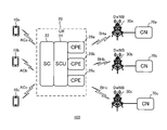
図1は、本実施形態に係る移動体通信システムが備える典型的な構成の例を示す模式図である。図1に示すように、移動体通信システム100は、端末装置10a,10b,10c、中継装置20、及びドナー基地局30a,30b,30cを備えて構成される。移動体通信システムが備える構成はこれに限定されない。移動体通信システムは、図1に示す構成の一部を備えなくてもよいし、他の構成をさらに備えてもよい。
図1は、本実施形態に係る移動体通信システムが備える典型的な構成の例を示す模式図である。図1に示すように、移動体通信システム100は、端末装置10a,10b,10c、中継装置20、及びドナー基地局30a,30b,30cを備えて構成される。移動体通信システムが備える構成はこれに限定されない。移動体通信システムは、図1に示す構成の一部を備えなくてもよいし、他の構成をさらに備えてもよい。
端末装置10a,10b,10cは、スマートフォン、携帯電話等の移動体通信端末である。端末装置は、図面ではUE(User Equipment)とも表記される。端末装置10aは、移動体通信事業者aに対応づけられた端末装置である。端末装置10bは、移動体通信事業者bに対応づけられた端末装置である。端末装置10cは、移動体通信事業者cに対応づけられた端末装置である。以下の説明において、端末装置10a、10b及び10cのそれぞれを区別する必要がない場合には、端末装置10a、10b又は10cを単に「端末装置10」と称する。
ドナー基地局30a,30b,30cは、いわゆるマクロセル(macro-cell)基地局としての構成を備える。ドナー基地局は、多数のマクロセル基地局のうち、端末装置や中継装置と無線ベアラによりバックホール通信路を確立しているものをいう。特にLTE規格では、ドナー基地局をDeNB(Donor eNodeB)と表記することもある。
ドナー基地局30aは、移動体通信事業者aに対応づけられたドナー基地局である。ドナー基地局30bは、移動体通信事業者bに対応づけられたドナー基地局である。ドナー基地局30cは、移動体通信事業者cに対応づけられたドナー基地局である。以下の説明において、ドナー基地局30a、30b及び30cのそれぞれを区別する必要がない場合には、ドナー基地局30a、30b又は30cを単に「ドナー基地局30」と称する。
ドナー基地局30は、各々が無線アクセスネットワーク(RAN: Radio Access Network)を形成するように動作する。ドナー基地局30は、中継装置20との間でバックホール通信路BHを確立するほか、端末装置10との間でも直接アクセス通信路ACを確立するように構成されている。ドナー基地局30は、相対的に高出力の電波を発生することによって、半径数百メートルから十数キロメートルのサービスエリアであるマクロセルを提供する。また、ドナー基地局30a、30b及び30cは、それぞれ移動体通信事業者a、b、cが保有するコアネットワーク70a、70b及び70cに接続されている。コアネットワーク70a、70b及び70cのそれぞれを区別する必要がない場合には、コアネットワーク70a、70b又は70cを単に「コアネットワーク70」と称する。
コアネットワーク70は、図示しないIPマルチメディアサブシステムを介して接続される管理ノードであり、EPC(Evolved Packet Core)とも呼ばれる。EPCはUEのモビリティ制御や認証機能、音声サービスサポート機能等を有する。。
中継装置20は、端末装置10とドナー基地局30との間の通信を中継する中継装置である。図1に示すように、中継装置20は、アクセス通信部22、分割統合部24、及びバックホール通信部26a,26b,26cを備える。図面では、中継装置20をUR(User Equipment Relay)とも称する。
上記構成要素により、本実施形態の中継装置20は、端末装置10とドナー基地局30との間の通信を中継するための次の中継方法を実施可能に構成されている。
(1)1以上の端末装置10と接続するステップ(アクセス通信部22)。
(2)特定の移動体通信事業者の識別情報に対応付けられたドナー基地局30との間で特定の移動体通信事業者の識別情報に対応付けられたバックホール通信路BHを各々確立するステップ(バックホール通信部26)。
(3)特定の移動体通信事業者の識別情報に対応づけられた端末装置10を特定の識別情報に対応付けられた特定のバックホール通信路BHと接続するステップ(分割統合部24)。
(1)1以上の端末装置10と接続するステップ(アクセス通信部22)。
(2)特定の移動体通信事業者の識別情報に対応付けられたドナー基地局30との間で特定の移動体通信事業者の識別情報に対応付けられたバックホール通信路BHを各々確立するステップ(バックホール通信部26)。
(3)特定の移動体通信事業者の識別情報に対応づけられた端末装置10を特定の識別情報に対応付けられた特定のバックホール通信路BHと接続するステップ(分割統合部24)。
以下、各ステップを実行する構成要素について具体的に説明する。
アクセス通信部22は、1以上の端末装置10との間の通信接続を確立する通信装置である。図1では、アクセス通信部22は、端末装置10a、端末装置10b、及び端末装置10cに共通に通信接続している。
アクセス通信部22は、1以上の端末装置10との間の通信接続を確立する通信装置である。図1では、アクセス通信部22は、端末装置10a、端末装置10b、及び端末装置10cに共通に通信接続している。
アクセス通信部22は、端末装置10に対して相対的に低出力の電波(信号)を発生することによって、半径数メートルから数十メートルのサービスエリアであるスモールセルを構築する。このことから、アクセス通信部22を、LTE規格では、ピコeNB(evolved NodeB)、フェムトeNB、又はホームeNBとも呼ぶ。図面ではアクセス通信部22をSC(Small-cell)と表記する。
アクセス通信部22は、いずれの端末装置10との間でも同一の周波数帯域の電波を介して接続し、アクセス通信路ACを形成している。アクセス通信部22は、各端末装置10から受信したアップリンクデータを復調し、パケットデータのブロックとして受信順に出力するようになっている。またアクセス通信部22は、分割統合部24から提供されたダウンリンクデータであるパケットデータのブロックを共通の周波数帯域の搬送波で変調してアクセス通信路ACを介して送信するようになっている。アップリンクデータ及びダウンリンクデータともに、複数のパケットデータのブロックにより構成されている。個々のブロックに付与されている識別情報により対応する移動体通信事業者を識別するようになっている。アクセス通信部22は、ハードウェアを主体として構成される。但し、アクセス通信部22を制御部がソフトウェアプログラムを実行することにより同様の機能を奏するように構成することも可能である。
バックホール通信部26a,26b,26cは、基地局との間で通信を確立する通信装置である。バックホール通信部26a,26b,26cは特に、特定の移動体通信事業者の識別情報に対応付けられた基地局のうち、ドナー基地局30との間で特定の識別情報に対応付けられたバックホール通信路BHを各々確立する。
バックホール通信部26aは、移動体通信事業者aに対応づけられたバックホール通信部である。バックホール通信部26bは、移動体通信事業者bに対応づけられたバックホール通信部である。バックホール通信部26cは、移動体通信事業者cに対応づけられたバックホール通信部である。また、以下の説明において、バックホール通信部26a、26b及び26cのそれぞれを区別する必要がない場合には、バックホール通信部26a、26b又は26cを単に「バックホール通信部26」と称する。
図1では、バックホール通信部26aが、移動体通信事業者aを示す特定の識別情報IDaに対応づけられたドナー基地局30aとの間でバックホール通信路BHaを確立している。バックホール通信部26bが、移動体通信事業者bを示す特定の識別情報IDbに対応づけられたドナー基地局30bとの間でバックホール通信路BHbを確立している。バックホール通信部26cが、移動体通信事業者cを示す特定の識別情報IDcに対応づけられたドナー基地局30cとの間でバックホール通信路BHcを確立している。バックホール通信路BHを介して送受信されるアップリンクデータ及びダウンリンクデータはそれぞれ対応するドナー基地局30が指定する周波数帯域の搬送波で変調された電波である。バックホール通信部26は、顧客構内装置(CPE:Customer Premises Equipment)とも呼ばれる。バックホール通信部26は、ハードウェアを主体として構成される。但し、バックホール通信部26を制御部がソフトウェアプログラムを実行することにより同様の機能を奏するように構成することも可能である。
バックホール通信部26が形成するバックホール通信路BHa,BHb,BHcは、空中線経由でパケットデータを伝送する経路である。パケットデータは通信規格に従った所定の変調方式に従って所定の周波数帯域の搬送波で変調されていてもよい。
分割統合部(SCU:Splitting and Combining Unit)24は、特定の移動体通信事業者の識別情報に対応づけられた端末装置10を特定の移動体通信事業者の識別情報に対応付けられた特定のバックホール通信路BHと接続するように構成されている。分割統合部24は、例えば、所定のハードウェアをソフトウェアで動作させることにより機能的に実現される。
図1に示した例において、移動体通信システム100は、移動体通信事業者a,b,cのそれぞれに対応付けられた装置又はその他の構成を有しているが、移動体通信事業者の数は3に限定されない。移動体通信システム100は、2事業者又は4事業者以上に対応付けられた装置又はその他の構成を有してもよい。
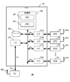
図2に、分割統合部24を中心とする中継装置20のハードウェア構成を例示する。図2に示すように、分割統合部24は、制御部200、記憶部204、インターフェース回路206及び210を備える。
制御部200は、中央処理装置(CPU:Central Processing Unit)201及びメモリ202を備えている。制御部200は、メモリ202に格納されるコンピュータプログラムをCPU201が実行することにより、分割統合部24を機能的に実現している。但し、分割統合部24をハードウェアのみにより同様の機能を奏するように構成することも可能である。
インターフェース回路206は、アクセス通信部22との間で統合データCDを送受信する接続手段である。インターフェース回路210は、各バックホール通信部26との分割データSDを送受信する接続手段である。
記憶部204は、書き込んだ順番でデータが読み出されるように構成されたメモリである。具体的には、アップリンクでは、アクセス通信部22が端末装置10からアンテナ222を介して受信し、インターフェース回路206経由で内部バスに供給したパケットデータを、記憶部204が順番に記憶する。そして制御部200の制御により記憶部204から順次読み出されたパケットデータは、移動体通信事業者の識別情報に対応づけられたブロック単位で移動体通信事業者の識別情報に対応づけられたインターフェース回路210を介してバックホール通信部26に転送され、アンテナ262からドナー基地局30に向けて送信される。また、ダウンリンクでは、バックホール通信部26がアンテナ262から受信してインターフェース回路210経由で内部バスに供給したパケットデータを、記憶部204が受信した順番に記憶していく。そして制御部200の制御により記憶部204から順次読み出されたパケットデータは、移動体通信事業者の識別情報に対応づけられたブロック単位で統合データCDとしてインターフェース回路206を介してアクセス通信部22に転送され、アンテナ222から端末装置10に向けて送信される。
なお、図2に示したブロック図は例示に過ぎず、異なる構成により同様の機能を奏するように構成することも可能である。例えば、上記ブロック図では、アップリンクデータ及びダウンリンクデータを制御部200の管理する内部バスに供給していたが、アクセス通信部22とバックホール通信部26とをバッファメモリを介して直結し、制御部200は全体の制御機能のみを奏するように構成することも可能である。このような構成は、通信速度が相対的に高かったりトラフィックの容量が大きかったりする場合に妥当な構成である。
図3を参照して、バックホール通信部26の機能を説明する。図3に示すように、移動体通信事業者を特定する識別情報に対応させてバックホール通信部26が複数並行して設けられている。
移動体通信事業者を特定する識別情報として、例えば、PLMN(Public Land Mobile Network)番号を利用可能である。PLMN番号は、3桁の国番号と事業者と特定する2-3桁のネットワーク番号で構成される。但し、移動体通信事業者の識別情報は、PLMN番号以外の体系で付与されていてもよい。以下、簡単のために、移動体通信事業者aの識別情報をIDaというように表記する。
図3では、バックホール通信部26aが、移動体通信事業者aを特定する識別情報IDaに対応づけられたドナー基地局30aとの間でバックホール通信路BHaを確立し、アクセス通信部22に接続する端末装置10aが移動体通信ネットワークMNaに接続されている。また、バックホール通信部26bが、移動体通信事業者bを特定する識別情報IDbに対応づけられたドナー基地局30bとの間でバックホール通信路BHaを確立し、アクセス通信部22に接続する端末装置10bが移動体通信ネットワークMNbに接続されている。さらに、バックホール通信部26cが、移動体通信事業者cを特定する識別情報IDcに対応づけられたドナー基地局30cとの間でバックホール通信路BHcを確立し、アクセス通信部22に接続する端末装置10cが移動体通信ネットワークMNcに接続されている。このように、事業が許可されている任意の移動体通信事業者xについて特定のバックホール通信路BHxを確立可能なバックホール通信部26xを設けることが可能である。
なお、バックホール通信部26や端末装置10は、接続先の制限手段を設けて、特定の移動体通信事業者のみ接続を許可し、他の移動体通信事業者への接続を禁止するように構成することが可能である。このような制限手段として、例えばSIM(Subscriber Identity Module)カードが挙げられる。一方、当該国の通信規制制度が許容していれば、任意の移動体通信事業者に接続先を変更可能に構成してもよい。接続先の変更は、SIMカードの差し替えや遠隔操作によるパラメータの書き換えによって実現可能である。
図4を参照して、分割統合部24の機能を説明する。図4に示すように、分割統合部24は、アクセス通信部22と複数のバックホール通信部26との間に設けられる。
分割統合部24は、アクセス通信部22から提供されたアップリンクデータを当該アップリンクデータに含まれる識別情報IDxに対応付けられたバックホール通信路BHxを確立しているバックホール通信部26xに供給する。具体的には、分割統合部24の識別情報判定部242がアップリンクデータに含まれている識別情報IDxを参照する。そして、当該識別情報IDxが付されているパケットデータのブロックを対応するバックホール通信部26xに供給する。この動作により、統合データCDが移動体通信事業者ごとの分割データSDに仕分けされることになる。
また分割統合部24は、1以上のバックホール通信路BHからのダウンリンクデータを順次アクセス通信部22に供給する。具体的に、バックホール通信部26により受信されて転送されてくるパケットデータを到着順にブロック毎に統合して統合データCDを生成する。この動作により、各移動体通信事業者から個別に送信されてきたしたパケットデータのブロックが統合されることになる。
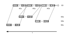
図5を参照して、アップリンクデータの分割動作を説明する。図5は、端末装置10b、10a、10cからこの順番で送信されたパケットデータのブロックACb,ACa、ACcが連結された統合データCDをバックホール通信路BHに分割して供給する場合を示している。各端末装置10からのパケットデータのブロックには、対応する移動体通信事業者を特定する識別情報IDb、IDa、IDcが付されている。分割統合部24は、記憶部204(図2参照)に、到着順にパケットデータのブロックを書き込んでいく。そして、分割統合部24は、記憶部204の機能により、書き込まれた順番でパケットデータのブロックを読み出す。読み出されたパケットデータのブロックは、識別情報IDxに応じて移動体通信事業者xごとに仕分けされた分割データSDxとして、バックホール通信部26xに供給される。供給された分割データSDxは、バックホール通信路BHxを介して対応する移動体通信ネットワークMNxに送信される。
図6を参照して、ダウンリンクデータの統合動作を説明する。図6は、移動体通信ネットワークMNa、MNc、MNbからこの順番でパケットデータのブロックがそれぞれのバックホール通信路BHa、BHc、BHb経由でバックホール通信部26a、26c、26bに供給された場合を示している。それぞれのパケットデータのブロックには、対応する移動体通信事業者を特定する識別情報IDa、IDc、IDbが付されている。各バックホール通信部26a、26c、26bは、到着順にパケットデータのブロックを出力する。分割統合部24は、出力順にパケットデータのブロックを記憶部204に書き込む。そして、分割統合部24は、記憶部204の機能により、書き込まれた順番でパケットデータのブロックを読み出し、統合データCDとしてアクセス通信部22へ出力する。アクセス通信部22は、共通する周波数帯域で順次パケットデータのブロックを送信する。各端末装置10a、10c、10bは、同一の周波数帯域で提供される全てのパケットデータを参照可能であるが、識別情報IDxにより自ら契約する移動体通信事業者xのために仕向けられたパケットデータのブロックのみを識別して受信する。
図7を参照して、中継装置20が記憶する近隣セル情報テーブルについて説明する。同図に示すように、中継装置20は、メモリ22aを有する。メモリ22aの所定の領域には、近隣セル情報テーブルが記憶されている。近隣セル情報テーブルは一般に、Neighbor Relation Table(NRT)と称される。近隣セル情報テーブルは、基地局により形成されるセルのうち、中継装置20の近隣セルの情報を記憶するテーブルである。中継装置20の近隣セルであるか否かは、例えば、中継装置20が基地局から受信する信号の品質又は強度に基づいて判断される。情報が記憶される近隣セルは、ドナー基地局により形成されるセルでもよいし、スモールセル基地局により形成されるセルであってもよい。中継装置20は、近隣セルのうち、端末装置10のハンドオーバ先セルの候補を特定するために、近隣セル情報テーブルを参照する。なお、近隣セル情報テーブルは、メモリ22aではなく、他の記憶部(例えば、メモリ202)に記憶されてもよい。
近隣セル情報テーブルには、セルを特定するための識別情報として、例えば、PCI(Physical Cell Identity)が含まれる。さらに、近隣セル情報テーブルには、各セルに対応付けられた移動体通信事業者を特定する識別情報として、例えば、PLMN番号が含まれる。メモリ22aは様々な方法で近隣セル情報テーブルを記憶可能である。以下に、近隣セルの情報を近隣セル情報テーブルに記憶する方法及び近隣セルの情報を取得する方法の例を説明する。
・実施例1
図8を参照して、近隣セルの情報を近隣セル情報テーブルに記憶する方法及び近隣セルの情報を取得する方法の実施例1を説明する。実施例1では、近隣セルの情報を取得するために、中継装置がネットワークリスニングを行う。ネットワークリスニングとは、近隣の基地局から発信された信号を受信し、当該信号から情報を取得することである。
図8を参照して、近隣セルの情報を近隣セル情報テーブルに記憶する方法及び近隣セルの情報を取得する方法の実施例1を説明する。実施例1では、近隣セルの情報を取得するために、中継装置がネットワークリスニングを行う。ネットワークリスニングとは、近隣の基地局から発信された信号を受信し、当該信号から情報を取得することである。
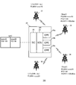
図8には、中継装置20、ドナー基地局31,32、及びスモールセル基地局33,34(例えば、ナノセル基地局又はフェムトセル基地局)を備える移動体通信システム101が示されている。以下に、中継装置20に、近隣セル情報テーブル(NRT)が記憶されるまでの処理を説明する。
中継装置20において、まず、バックホール通信部26がドナー基地局31,32から受信する信号の品質に基づいて、バックホール通信路を確立する。具体的には、バックホール通信部26は、受信する信号の品質が一定水準以上であるドナー基地局との間でバックホール通信路を確立する。信号の品質は、例えば、RSRP(Reference Signal Received Power)、RSRQ(Reference Signal Received Quality)、又はSINR(Signal to Interference plus Noise Ratio)に基づいて判断される。その後、確立されたバックホール通信路に対応する移動体通信事業者に応じたPLMNがバックホール通信部26から分割統合部24を介してアクセス通信部22に出力される。
また、アクセス通信部22は、分割統合部24から受信したPLMNを含むNRTを生成し、メモリ22a(図7参照。)に記憶する。アクセス通信部22はさらに、当該PLMNを含む信号を乗せてアクセス通信路への電波を送信する。
図8の例では、PLMNとして、ドナー基地局31のPLMNである「xxxx10」及びドナー基地局32のPLMNである「xxxx20」がNRTに記憶されている。すなわち、この例では、バックホール通信部26がドナー基地局31及び32から受信した信号の品質が一定水準以上であったため、ドナー基地局31及び32のPLMNがNRTに記憶されたことになる。
中継装置20は、アクセス通信部22に記憶された各PLMNについて、ネットワークリスニングを行うことにより、中継装置20の近隣セル(Ncell)をサーチし、受信信号の品質が一定水準以上である近隣セルのPCIをNRTに記憶する。信号の品質は、上記と同様に、例えば、RSRP、RSRQ、又はSINRに基づいて判断される。
ここで、複数の移動体通信事業者に対応するバックホール通信路が確立された場合、PCIを記憶するためのメモリ22aにおける領域は、バックホール通信路を確立したドナー基地局に対応付けられたPLMNごとに、所定のサイズで予めメモリ22aに確保される。すなわち、PCIを記憶するためのメモリ22aにおける領域は、確立されたバックホール通信路に対応する移動体通信事業者の識別情報ごとに、所定のサイズで予めメモリ22aに確保される。
図8の例では、PLMNが「xxxx10」であるスモールセル基地局33が形成する近隣セルのPCIである「105」がPLMN「xxxx10」に対応付けられてNRTに記憶されている。また、PLMNが「xxxx20」であるスモールセル基地局34が形成する近隣セルのPCIである「88」がPLMN「xxxx20」に対応付けられてNRTに記憶されている。
図8の例では、バックホール通信路が確立されたときに、PLMN「xxxx10」に対応付けて記憶されるPCI(近隣セルの情報)を記憶するための領域と、PLMN「xxxx20」に対応付けて記憶されるPCIを記憶するための領域は、それぞれメモリ22aに所定のサイズで確保される。例えば、PLMN「xxxx10」及び「xxxx20」に対応付けられた領域のサイズは、それぞれ、均等に割り当てられる。このとき、特定のPLMNに関して、割り当てられたサイズを超える容量の近隣セルの情報を記憶することができない。
近隣セルの情報をメモリ22aに記憶する他の方法として、PLMNのそれぞれに対して優先順位を付け、当該優先順位に応じたサイズの記憶領域が割り当てられてもよい。すなわち、確立されたバックホール通信路に対応するPLMN(識別情報)ごとにメモリ22aに記憶領域が確保され、ある記憶領域(第一の領域)は、他の記憶領域(第二の領域)の容量に対して所定の比率の容量で確保される。または、記憶される領域のサイズが均等又は公平になるように、隣接セルに対応するPLMNに応じて定められた所定の順番で、PLMNごとに確保されている複数の領域のそれぞれに対して、記憶されてもよい。例えば、PLMN「xxxx10」及び「xxxx20」のそれぞれについて、近隣セルの情報を記憶するための領域がメモリ22aに確保されているとする。このとき、「xxxx10」のPCI、「xxxx20」のPCI、「xxxx10」のPCI、「xxxx20」のPCI・・・の順番で順次CPIを記憶する。このようにPCIを記憶することにより、特定のPLMNに対応するPCIが多く記憶されてしまうことを抑制することができる。
NRTに記憶される情報は定期的に更新される。例えば、あるPCIがNRTに記憶された後、当該PCIに対応するセルを形成する基地局からバックホール通信部26が受信した信号の品質が所定の水準を下回った場合、当該PCIはNRTから削除される。すなわち、中継装置20の近隣セルを形成する基地局からバックホール通信部26が受信した信号の品質が所定の水準を下回った場合、当該近隣セルの情報は記憶部(メモリ22a)から削除される。基地局からの受信信号の品質の水準は、上記と同様に、例えば、RSRP、RSRQ、又はSINRに基づいて判断される。
以上のように実施例1によれば、中継装置20のメモリ22aにおいて近隣セルの情報(PCI)を記憶するための領域は、確立されたバックホール通信路に対応する識別情報(PLMN)ごとに、所定のサイズ(又は所定の比率)で予め確保されている。例えば、特定のPLMNに対応付けられた近隣セルの情報(第一の近隣セルの情報)が他のPLMNに対応付けられた近隣セルの情報(第二の近隣セルの情報)よりも先に多く検知されたとする。この場合であっても、中継装置20のメモリ22aのNRTのための領域の大部分に第一の近隣セルの情報が記憶されてしまい、後から検出された第二の近隣セルの情報を記憶するための領域が十分に確保されないという問題を回避できる。すなわち、実施例1によれば、複数事業者間でより公平に近隣セルの情報を中継装置20に記憶することができる。
また、実施例1によれば、あるPCIがNRTに記憶された後、当該PCIに対応するセルを形成する基地局からの受信信号の品質が一定水準を下回った場合、当該PCIはNRTから削除される。そのため、サイズが有限であるメモリ22aの記憶領域を効率的に使用することができる。
・実施例2
図9を参照して、実施例2を説明する。実施例2では、中継装置は、端末装置から受信した測定報告(Measurement Report)から近隣セルの情報を取得する。
図9を参照して、実施例2を説明する。実施例2では、中継装置は、端末装置から受信した測定報告(Measurement Report)から近隣セルの情報を取得する。
図9に示すように、移動体通信システム102は、端末装置11,12、中継装置20、ドナー基地局31,32、及びスモールセル基地局33,34(例えば、ナノセル基地局又はフェムトセル基地局)を備える。セルC10は、中継装置20により形成されるセルである。端末装置11,12は、セルC10に在圏している。以下に、中継装置20に、近隣セル情報テーブル(NRT)が記憶されるまでの処理を説明する。
実施例1と同様に、中継装置20において、まず、バックホール通信部26がドナー基地局31,32から受信する信号の品質に基づいて、バックホール通信路を確立する。具体的には、バックホール通信部26は、受信する信号の品質が一定水準以上であるドナー基地局との間でバックホール通信路を確立する。その後、確立されたバックホール通信路に対応する移動体通信事業者に応じたPLMNがバックホール通信部26から分割統合部24を介してアクセス通信部22に出力される。
また、アクセス通信部22は、分割統合部24から受信したPLMNを含むNRTを生成し、メモリ22aに記憶する。図9に示す例では、「xxxx10」及び「xxxx20」がPLMNとして、NRTに記憶されている。アクセス通信部22はさらに、当該PLMNを含む信号を乗せてアクセス通信路への電波を発生する。
中継装置20は、セルC10に在圏する端末装置11,12から送信された測定報告を受信する。測定報告は、近隣セルの数、当該近隣セルの識別情報及び当該近隣セルにおける通信品質を示す情報、例えば、RSRP、RSRQなどを含む。図9の例では、端末装置11から中継装置20に送信された測定報告MR1には、スモールセル基地局33が形成するセルのPCI「105」及びRSRP「-100dBm」が含まれることが示されている。また、端末装置12から中継装置20に送信された測定報告MR2には、スモールセル基地局34が形成するセルのPCI「88」及びRSRP「-105dBm」が含まれることが示されている。
中継装置20は、バックホール通信部26がスモールセル基地局33,34から受信した測定報告に含まれるRSRP及びRSRQなどの品質情報に基づく品質が一定水準以上である近隣セルを特定する。中継装置20は、当該特定された近隣セルのPCIを対応するPLMNに関連付けてメモリ22aのNRTに記憶する。すなわち、バックホール通信部26が近隣セルを形成する基地局から受信した測定報告に含まれる品質情報に基づく品質が一定水準以上である近隣セルの情報が、対応する識別情報(PLMN)に関連付けて記憶部(メモリ22a)に記憶される。図9の例では、PLMNが「xxxx10」であるスモールセル基地局33が形成する近隣セルのPCIである「105」がPLMN「xxxx10」に対応付けられてNRTに記憶されている。また、PLMNが「xxxx20」であるスモールセル基地局34が形成する近隣セルのPCIである「88」がPLMN「xxxx20」に対応付けられてNRTに記憶されている。
近隣セルの情報を記憶するための領域の確保の方法、各記憶領域へ記憶する順番、及び近隣セルの情報を削除する方法は、実施例1と同様である。
・実施例3
図10を参照して、実施例3を説明する。実施例3では、端末装置のハンドオーバを禁止する。
図10を参照して、実施例3を説明する。実施例3では、端末装置のハンドオーバを禁止する。
図10に示すように、移動体通信システム103は、端末装置11,12、中継装置20、ドナー基地局31,32、及びスモールセル基地局33,34を備える。セルC10は、中継装置20により形成されるセルである。端末装置11,12は、セルC10に在圏している。
中継装置20において、まず、バックホール通信部26は、ドナー基地局31,32から信号を受信し、当該信号の品質が一定水準以上であるドナー基地局との間にバックホール通信路を確立する。その後、確立されたバックホール通信路に対応する移動体通信事業者に応じたPLMNがバックホール通信部26から分割統合部24を介してアクセス通信部22に出力される。
また、アクセス通信部22は、分割統合部24から受信したPLMNを含むNRTを生成し、メモリ22aに記憶する。図10に示す例では、「xxxx10」及び「xxxx20」がPLMNとして、NRTに記憶されている。アクセス通信部22はさらに、当該PLMNを含む信号を乗せてアクセス通信路への電波を送信する。
本実施例において、複数の移動体通信事業者についてのバックホール通信路が確立され、複数のPLMNがアクセス通信路へ送信される場合、アクセス通信部22は、NRTに近隣セルの情報(PCI)を記憶しない。すなわち、中継装置20は、端末装置のハンドオーバ先候補の情報を記憶せず、ハンドオーバの機能を停止する。
・実施例4
図11を参照して、実施例4を説明する。実施例4では、中継装置は、ハンドオーバ先候補の情報として、ドナー基地局が形成するセルの情報をNRTに記憶する。
図11を参照して、実施例4を説明する。実施例4では、中継装置は、ハンドオーバ先候補の情報として、ドナー基地局が形成するセルの情報をNRTに記憶する。
図11に示すように、移動体通信システム104は、中継装置20、ドナー基地局31,32、及びスモールセル基地局33,34を備える。
中継装置20において、バックホール通信部26がドナー基地局31,32から信号を受信し、当該信号の品質が一定水準以上であるドナー基地局との間でバックホール通信路を確立する。その後、確立されたバックホール通信路に対応する移動体通信事業者に応じたPLMNがバックホール通信部26から分割統合部24を介してアクセス通信部22に出力される。
さらに、バックホール通信部26は、ドナー基地局31,32が形成するセルのPCIを受信する。当該PCIは、分割統合部24を介してアクセス通信部22に出力される。
また、アクセス通信部22は、分割統合部24から受信したPLMN及びPCIを含むNRTを生成し、メモリ22aに記憶する。PCIは、対応するPLMNに関連付けて記憶される。
図11に示す例では、ドナー基地局31のPLMN「xxxx10」と、ドナー基地局32のPLMN「xxxx20」がNRTに記憶されている。また、ドナー基地局31が形成するセルのPCI「209」がドナー基地局31のPLMNに対応付けてNRTに記憶されている。ドナー基地局32が形成するセルのPCI「173」がドナー基地局32のPLMNに対応付けてNRTに記憶されている。
アクセス通信部22は、ハンドオーバ先候補の情報として、ドナー基地局31,32が形成するセルの情報をNRTに記憶する。
以上のように本実施例によれば、中継装置は、ハンドオーバ先候補の情報として、ドナー基地局が形成するセルの情報をNRTに記憶する。そのため、実施例1乃至3と比べてより簡便にNRTに近隣セルの情報を記憶することが可能となる。
・実施例5
図12を参照して、実施例5を説明する。実施例5では、中継装置は、近隣のドナー基地局が記憶するNRTを当該ドナー基地局から取得し、当該NRTに含まれる近隣セルの情報を記憶する。
図12を参照して、実施例5を説明する。実施例5では、中継装置は、近隣のドナー基地局が記憶するNRTを当該ドナー基地局から取得し、当該NRTに含まれる近隣セルの情報を記憶する。
図12に示すように、移動体通信システム105は、中継装置20、ドナー基地局31,32、及びスモールセル基地局33,34を備える。
中継装置20において、バックホール通信部26がドナー基地局31,32から信号を受信し、当該信号の品質が一定水準以上であるドナー基地局との間でバックホール通信路を確立する。その後、確立されたバックホール通信路に対応する移動体通信事業者に応じたPLMNがバックホール通信部26から分割統合部24を介してアクセス通信部22に出力される。
さらに、バックホール通信部26は、ドナー基地局31,32が記憶しているNRTをドナー基地局31,32から受信する。ドナー基地局31が記憶するNRTには、スモールセル基地局33が形成するセルの情報(PCI 105)が含まれる。ドナー基地局32が記憶するNRTには、スモールセル基地局34が形成するセルの情報(PCI 88)が含まれる。ドナー基地局31,32から受信したNRTに含まれる近隣セルの情報(PCI)は、分割統合部24を介してアクセス通信部22に出力される。
アクセス通信部22は、分割統合部24から受信したPLMN及びPCIを含むNRTを生成し、メモリ22aに記憶する。PCIは、対応するPLMNに関連付けて記憶される。
図12に示す例では、ドナー基地局31のPLMN「xxxx10」と、ドナー基地局32のPLMN「xxxx20」が中継装置20のNRTに記憶されている。また、ドナー基地局31が記憶しているNRTに含まれるPCI「105」がドナー基地局31のPLMN「xxxx10」に対応付けて中継装置20のNRTに記憶されている。ドナー基地局32が記憶しているNRTに含まれるPCI「88」がドナー基地局32のPLMN「xxxx20」に対応付けて中継装置20のNRTに記憶されている。
以上のように本実施例によれば、中継装置20のバックホール通信部26は、近隣のドナー基地局が記憶するNRTを当該ドナー基地局から受信し、メモリ22aに予め確保された領域は、当該受信したNRTに含まれる当該ドナー基地局の近隣セルの情報を記憶する。そのため、中継装置20は、自機で近隣セルの情報をサーチしなくても近隣セルの情報を取得可能である。従って、中継装置20は、簡易な構成により実現可能である。
・実施例6
図13を参照して、実施例6を説明する。実施例6では、中継装置は、自機の位置に基づいてサーバ装置から近隣セルの情報を取得し、記憶する。
図13を参照して、実施例6を説明する。実施例6では、中継装置は、自機の位置に基づいてサーバ装置から近隣セルの情報を取得し、記憶する。
図13に示すように、移動体通信システム106は、中継装置20、ドナー基地局31、スモールセル基地局33、及びサーバ装置40を備える。
中継装置20において、まず、バックホール通信部26がドナー基地局31から信号を受信し、当該信号の品質が一定水準以上であるときに、ドナー基地局31との間でバックホール通信路を確立する。その後、確立されたバックホール通信路に対応する移動体通信事業者に応じたPLMNがバックホール通信部26から分割統合部24を介してアクセス通信部22に出力される。
アクセス通信部22は、分割統合部24から受信したPLMNを含むNRTを生成し、メモリ22aに記憶する。図13に示す例では、「xxxx10」がPLMNとして、NRTに記憶されている。アクセス通信部22はさらに、当該PLMNを含む信号を乗せてアクセス通信路への電波を送信する。
本実施例において、中継装置20は、測位部27を備える。測位部27は、GPS(Global Positioning System)などにより、中継装置20を測位する。測位の実施は、GPSを使用するものに限定せず、任意の方法を採用可能である。
中継装置20は、測位部27により特定された自機の位置情報(例えば、緯度経度情報)をサーバ装置40に送信する。サーバ装置40は、各基地局が形成するセルの情報及び当該基地局の位置情報を予め記憶している。サーバ装置40は、中継装置20から受信した位置情報に基づいて、中継装置20の近隣セル(例えば、中継装置20から500m以内のセル)を特定し、特定された近隣セルの情報を中継装置20に送信する。
中継装置20は、受信した近隣セルの情報を含むNRTを生成し、メモリ22aに記憶する。図13に示す例では、PLMN「xxxx10」に対応付けて、PCI「105」がNRTに記憶されている。
・実施例7
上記の実施例1から3及び6は、中継装置20のように、複数の移動体通信事業者の運営するネットワークに接続できる中継装置ではなく、一般的な中継装置に対しても適用可能である。
上記の実施例1から3及び6は、中継装置20のように、複数の移動体通信事業者の運営するネットワークに接続できる中継装置ではなく、一般的な中継装置に対しても適用可能である。
詳細には、次の手法は、一般的な中継装置に対しても適用可能である。
・中継装置がネットワークリスニングを行って近隣セルの情報を取得する。
・中継装置が端末装置から受信した測定報告から近隣セルの情報を取得する。
・端末装置のハンドオーバを禁止する。
・中継装置は、自機の位置に基づいてサーバ装置から近隣セルの情報を取得し、記憶する。
・中継装置がネットワークリスニングを行って近隣セルの情報を取得する。
・中継装置が端末装置から受信した測定報告から近隣セルの情報を取得する。
・端末装置のハンドオーバを禁止する。
・中継装置は、自機の位置に基づいてサーバ装置から近隣セルの情報を取得し、記憶する。
・実施例8
上記の実施例1から7のそれぞれは、一つ又は複数の他の実施例の少なくとも一部と組み合わせて実施可能である。
上記の実施例1から7のそれぞれは、一つ又は複数の他の実施例の少なくとも一部と組み合わせて実施可能である。
<その他の実施の形態>
以上のとおり本発明の実施形態を説明したが、この実施形態の開示に限定されるものと理解するべきではない。本発明は、上記実施形態に限定されることなく種々に変形して適用することが可能である。
以上のとおり本発明の実施形態を説明したが、この実施形態の開示に限定されるものと理解するべきではない。本発明は、上記実施形態に限定されることなく種々に変形して適用することが可能である。
具体的には、上記各実施形態では、通信規格がLTEであることを前提として記載したが、これに限られない。例えば、LTEの後継規格となる5Gなどでも、本願発明を適用することが可能である。
10…端末装置、20…中継装置、22…アクセス通信部、24…分割統合部、26…バックホール通信部、30…ドナー基地局、40…サーバ装置、100,101,102,103,104,105,106…移動体通信システム
Claims (8)
- 端末装置とドナー基地局との間の通信を中継する中継装置であって、
特定の移動体通信事業者の識別情報に対応付けられた基地局のうち、ドナー基地局との間でバックホール通信路を各々確立する複数のバックホール通信部と、
前記基地局が形成するセルのうち、前記中継装置の近隣セルの情報を前記基地局から受信した信号に基づいて記憶する記憶部と、
を備え、
前記近隣セルの情報を記憶するための前記記憶部における領域は、前記確立されたバックホール通信路に対応する前記識別情報ごとに、確保される、中継装置。 - 前記確立されたバックホール通信路に対応する前記識別情報ごとに確保される前記領域は、他の前記領域の容量に対して所定の比率の容量で確保される、請求項1に記載の中継装置。
- 前記近隣セルを形成する基地局から前記バックホール通信部が受信した信号の品質が所定の水準を下回った場合、当該近隣セルの情報は前記記憶部から削除される、請求項1又は2に記載の中継装置。
- 前記近隣セルの情報は、前記近隣セルに対応する前記識別情報に応じて定められた所定の順番で、前記識別情報ごとに確保されている複数の前記領域のそれぞれに対して、記憶される、請求項1から3のいずれか一項に記載の中継装置。
- 1以上の端末装置と通信可能なアクセス通信部と、
前記端末装置から前記アクセス通信部が受信した測定報告に含まれる品質情報に基づく品質が一定水準以上である前記近隣セルの情報が、対応する前記識別情報に関連付けて前記記憶部に記憶される、請求項1から4のいずれか一項に記載の中継装置。 - 前記近隣セルの情報を記憶するための領域は、前記ドナー基地局が形成するセルの情報を前記近隣セルの情報として記憶する、請求項1から5のいずれか一項に記載の中継装置。
- 前記バックホール通信部は、前記ドナー基地局が記憶する当該ドナー基地局の近隣セルの情報を受信し、
前記近隣セルの情報を記憶するための領域は、前記バックホール通信部が受信した前記近隣セルの情報を記憶する、請求項1から6のいずれか一項に記載の中継装置。 - 端末装置とドナー基地局との間の通信を中継する中継装置により実施される中継方法であって、
特定の移動体通信事業者の識別情報に対応付けられた基地局のうち、ドナー基地局との間でバックホール通信路を各々確立することと、
前記基地局が形成するセルのうち、前記中継装置の近隣セルの情報を前記基地局から受信した信号に基づいて記憶部に記憶することと、
を含み、
前記近隣セルの情報を記憶するための前記記憶部における領域は、前記確立されたバックホール通信路に対応する前記識別情報ごとに、確保される、中継方法。
Priority Applications (2)
| Application Number | Priority Date | Filing Date | Title |
|---|---|---|---|
| JP2021515716A JP7260634B2 (ja) | 2019-04-26 | 2019-04-26 | 中継装置及び中継方法 |
| PCT/JP2019/018043 WO2020217486A1 (ja) | 2019-04-26 | 2019-04-26 | 中継装置及び中継方法 |
Applications Claiming Priority (1)
| Application Number | Priority Date | Filing Date | Title |
|---|---|---|---|
| PCT/JP2019/018043 WO2020217486A1 (ja) | 2019-04-26 | 2019-04-26 | 中継装置及び中継方法 |
Publications (1)
| Publication Number | Publication Date |
|---|---|
| WO2020217486A1 true WO2020217486A1 (ja) | 2020-10-29 |
Family
ID=72940898
Family Applications (1)
| Application Number | Title | Priority Date | Filing Date |
|---|---|---|---|
| PCT/JP2019/018043 Ceased WO2020217486A1 (ja) | 2019-04-26 | 2019-04-26 | 中継装置及び中継方法 |
Country Status (2)
| Country | Link |
|---|---|
| JP (1) | JP7260634B2 (ja) |
| WO (1) | WO2020217486A1 (ja) |
Cited By (1)
| Publication number | Priority date | Publication date | Assignee | Title |
|---|---|---|---|---|
| US20220174519A1 (en) * | 2019-03-28 | 2022-06-02 | Apple Inc. | Physical layer cell identifier (pci) configuration and automatic neighbor relations (anr) for 5g networks |
Citations (3)
| Publication number | Priority date | Publication date | Assignee | Title |
|---|---|---|---|---|
| WO2012035697A1 (ja) * | 2010-09-17 | 2012-03-22 | パナソニック株式会社 | 基地局及び通信システム |
| WO2013069170A1 (ja) * | 2011-11-07 | 2013-05-16 | パナソニック株式会社 | 中継局、基地局及び帯域割当方法 |
| JP2016513380A (ja) * | 2013-01-24 | 2016-05-12 | ノキア テクノロジーズ オーユー | セル再選択方法および装置 |
-
2019
- 2019-04-26 JP JP2021515716A patent/JP7260634B2/ja active Active
- 2019-04-26 WO PCT/JP2019/018043 patent/WO2020217486A1/ja not_active Ceased
Patent Citations (3)
| Publication number | Priority date | Publication date | Assignee | Title |
|---|---|---|---|---|
| WO2012035697A1 (ja) * | 2010-09-17 | 2012-03-22 | パナソニック株式会社 | 基地局及び通信システム |
| WO2013069170A1 (ja) * | 2011-11-07 | 2013-05-16 | パナソニック株式会社 | 中継局、基地局及び帯域割当方法 |
| JP2016513380A (ja) * | 2013-01-24 | 2016-05-12 | ノキア テクノロジーズ オーユー | セル再選択方法および装置 |
Cited By (2)
| Publication number | Priority date | Publication date | Assignee | Title |
|---|---|---|---|---|
| US20220174519A1 (en) * | 2019-03-28 | 2022-06-02 | Apple Inc. | Physical layer cell identifier (pci) configuration and automatic neighbor relations (anr) for 5g networks |
| US12464383B2 (en) * | 2019-03-28 | 2025-11-04 | Apple Inc. | Physical layer cell identifier (PCI) configuration and automatic neighbor relations (ANR) for 5G networks |
Also Published As
| Publication number | Publication date |
|---|---|
| JPWO2020217486A1 (ja) | 2020-10-29 |
| JP7260634B2 (ja) | 2023-04-18 |
Similar Documents
| Publication | Publication Date | Title |
|---|---|---|
| US8494441B2 (en) | Identification of relay base stations in wireless networks | |
| CN101529941B (zh) | 用于估计无线通信网络中接入点的位置的方法和设备 | |
| US9955391B2 (en) | Enhanced cell global identifier-based handover from an eNodeB to a home eNodeB | |
| US20130215820A1 (en) | Relay Nodes | |
| US8874118B2 (en) | Base station, communication method and wireless communication system | |
| CN116325598B (zh) | 经由侧链路连接作为中继进行操作的用户装备 | |
| US20220312178A1 (en) | Sidelink relay selection | |
| US8554230B2 (en) | Method and apparatus for allocating femto cell information for handover in a wireless communication system | |
| US9042934B2 (en) | Method for controlling interference in a radio communications system and apparatus thereof | |
| EP3282759A1 (en) | Cross-menb switching method and apparatus and base station | |
| JP7260634B2 (ja) | 中継装置及び中継方法 | |
| US20180213385A1 (en) | Wireless terminal apparatus, network node, and method | |
| US12279199B2 (en) | Method and apparatus for supporting service continuity in NPN using NWDAF | |
| JP6788754B1 (ja) | 移動体通信システム及びその制御方法 | |
| JP7386254B2 (ja) | 中継装置、中継方法、及び中継システム | |
| US20180310271A1 (en) | Wireless communications system, control station, and terminal | |
| JP7350079B2 (ja) | 中継装置、中継方法、及びプログラム | |
| JP7260644B2 (ja) | 中継装置及び中継方法 | |
| US20240340632A1 (en) | Systems and methods for identifying subscription-based unmanned aerial vehicle (uav) | |
| EP2337381B1 (en) | Wireless base station, wireless network controller, and automatic networking method | |
| WO2025065621A1 (en) | Systems and methods for inter-donor migration | |
| US20260095966A1 (en) | Systems and methods for configuring unmanned aerial vehicle (uav) multi-rat dual connectivity (mrdc) | |
| CN116803012B (zh) | 一种无线通信的方法和装置 | |
| Gupta | NextG Managed Access Systems (N-MAS) for Correctional-Facility Markets | |
| WO2021182842A1 (en) | Method and system for connecting to an lte cell |
Legal Events
| Date | Code | Title | Description |
|---|---|---|---|
| 121 | Ep: the epo has been informed by wipo that ep was designated in this application |
Ref document number: 19925931 Country of ref document: EP Kind code of ref document: A1 |
|
| ENP | Entry into the national phase |
Ref document number: 2021515716 Country of ref document: JP Kind code of ref document: A |
|
| NENP | Non-entry into the national phase |
Ref country code: DE |
|
| 122 | Ep: pct application non-entry in european phase |
Ref document number: 19925931 Country of ref document: EP Kind code of ref document: A1 |