WO2020213738A1 - 熱交換器用タンクのコアプレート - Google Patents
熱交換器用タンクのコアプレート Download PDFInfo
- Publication number
- WO2020213738A1 WO2020213738A1 PCT/JP2020/016983 JP2020016983W WO2020213738A1 WO 2020213738 A1 WO2020213738 A1 WO 2020213738A1 JP 2020016983 W JP2020016983 W JP 2020016983W WO 2020213738 A1 WO2020213738 A1 WO 2020213738A1
- Authority
- WO
- WIPO (PCT)
- Prior art keywords
- core plate
- flat
- rib
- heat exchanger
- tank
- Prior art date
- Legal status (The legal status is an assumption and is not a legal conclusion. Google has not performed a legal analysis and makes no representation as to the accuracy of the status listed.)
- Ceased
Links
Images


Classifications
-
- F—MECHANICAL ENGINEERING; LIGHTING; HEATING; WEAPONS; BLASTING
- F28—HEAT EXCHANGE IN GENERAL
- F28D—HEAT-EXCHANGE APPARATUS, NOT PROVIDED FOR IN ANOTHER SUBCLASS, IN WHICH THE HEAT-EXCHANGE MEDIA DO NOT COME INTO DIRECT CONTACT
- F28D1/00—Heat-exchange apparatus having stationary conduit assemblies for one heat-exchange medium only, the media being in contact with different sides of the conduit wall, in which the other heat-exchange medium is a large body of fluid, e.g. domestic or motor car radiators
- F28D1/02—Heat-exchange apparatus having stationary conduit assemblies for one heat-exchange medium only, the media being in contact with different sides of the conduit wall, in which the other heat-exchange medium is a large body of fluid, e.g. domestic or motor car radiators with heat-exchange conduits immersed in the body of fluid
- F28D1/04—Heat-exchange apparatus having stationary conduit assemblies for one heat-exchange medium only, the media being in contact with different sides of the conduit wall, in which the other heat-exchange medium is a large body of fluid, e.g. domestic or motor car radiators with heat-exchange conduits immersed in the body of fluid with tubular conduits
- F28D1/053—Heat-exchange apparatus having stationary conduit assemblies for one heat-exchange medium only, the media being in contact with different sides of the conduit wall, in which the other heat-exchange medium is a large body of fluid, e.g. domestic or motor car radiators with heat-exchange conduits immersed in the body of fluid with tubular conduits the conduits being straight
-
- F—MECHANICAL ENGINEERING; LIGHTING; HEATING; WEAPONS; BLASTING
- F28—HEAT EXCHANGE IN GENERAL
- F28F—DETAILS OF HEAT-EXCHANGE AND HEAT-TRANSFER APPARATUS, OF GENERAL APPLICATION
- F28F1/00—Tubular elements; Assemblies of tubular elements
- F28F1/02—Tubular elements of cross-section which is non-circular
-
- F—MECHANICAL ENGINEERING; LIGHTING; HEATING; WEAPONS; BLASTING
- F28—HEAT EXCHANGE IN GENERAL
- F28F—DETAILS OF HEAT-EXCHANGE AND HEAT-TRANSFER APPARATUS, OF GENERAL APPLICATION
- F28F9/00—Casings; Header boxes; Auxiliary supports for elements; Auxiliary members within casings
- F28F9/02—Header boxes; End plates
-
- F—MECHANICAL ENGINEERING; LIGHTING; HEATING; WEAPONS; BLASTING
- F28—HEAT EXCHANGE IN GENERAL
- F28F—DETAILS OF HEAT-EXCHANGE AND HEAT-TRANSFER APPARATUS, OF GENERAL APPLICATION
- F28F9/00—Casings; Header boxes; Auxiliary supports for elements; Auxiliary members within casings
- F28F9/02—Header boxes; End plates
- F28F9/04—Arrangements for sealing elements into header boxes or end plates
- F28F9/16—Arrangements for sealing elements into header boxes or end plates by permanent joints, e.g. by rolling
Definitions
- the present invention relates to a core plate of a heat exchanger tank.
- Many heat exchanger tanks consist of a combination of a tank body with one end open and a core plate that closes the opening.
- a large number of flat holes 3a are arranged in parallel inside an annular groove 7a formed on the peripheral edge of the core plate 2a, and an end portion of a flat tube 4a is inserted into the core plate.
- the insertion part is brazed and fixed.
- ribs 9 for reducing the thermal stress generated in the flat tube, particularly the thermal stress concentrated on both ends in the width direction of the flat tube at the joint between the core plate and the flat tube. It is formed.
- an object of the present invention is to provide a core plate of a tank for a heat exchanger, which can further reduce the thermal stress generated in the flat tube.
- a tank of a heat exchanger is formed by an elongated tank body 1 having an opening on the opposite side of the bottom surface and a core plate 2 closing the opening.
- a large number of flat holes 3 having a major axis 3a located in the width direction thereof are arranged in parallel at regular intervals in parallel with each other, and burring protruding toward the inner surface side of the tank at the hole edge of each flat hole 3.
- the end portion of the flat tube 4 is inserted into each flat hole 3, and the insertion portion is brazed.
- the core plate 2 has a continuous rib 5 that is parallel to the flat hole 3 and longer than the flat hole 3 at an intermediate position between adjacent flat holes 3 and projects toward the outer surface side of the core plate 2.
- the rib 5 is formed at an intermediate position in the longitudinal direction of the flat hole 3 with an intermediate rib 5a formed shallowly (t1) with respect to the root of the burring process 6 and deeply (t2) at both end positions.
- It is a core plate of a tank for a heat exchanger characterized by having an end rib 5b.
- a tank of a heat exchanger is formed by an elongated tank body 1 having an opening on the opposite side of the bottom surface and a core plate 2 closing the opening.
- a large number of flat holes 3 having a major axis 3a located in the width direction thereof are arranged in parallel at regular intervals in parallel with each other, and burring protruding toward the inner surface side of the tank at the hole edge of each flat hole 3.
- the end portion of the flat tube 4 is inserted into each flat hole 3, and the insertion portion is brazed.
- the core plate 2 has a continuous rib 5 that is parallel to the flat hole 3 and longer than the flat hole 3 at an intermediate position between adjacent flat holes 3 and projects toward the outer surface side of the core plate 2.
- the rib 5 has a narrow portion 5c formed at an intermediate position in the longitudinal direction of the flat hole 3 with narrow skirts on both sides thereof (d1), and a narrow portion 5c formed at both ends, the width of the skirts on both sides thereof. It is a core plate of a heat exchanger tank having a wide portion 5d formed widely (d2). According to the third aspect of the present invention, a tank of a heat exchanger is formed by an elongated tank body 1 having an opening on the opposite side of the bottom surface and a core plate 2 closing the opening.
- a large number of flat holes 3 having a major axis 3a located in the width direction thereof are arranged in parallel at regular intervals in parallel with each other, and burring protruding toward the inner surface side of the tank at the hole edge of each flat hole 3.
- the end portion of the flat tube 4 is inserted into each flat hole 3, and the insertion portion is brazed.
- the core plate 2 has a continuous rib 5 that is parallel to the flat hole 3 and longer than the flat hole 3 at an intermediate position between adjacent flat holes 3 and projects toward the outer surface side of the core plate 2.
- the rib 5 is formed at an intermediate position in the longitudinal direction of the flat hole 3 with an intermediate rib 5a formed shallowly (t1) with respect to the root of the burring process 6 and deeply (t2) at both end positions. It has an end rib 5b and The rib 5 has a narrow portion 5c formed at an intermediate position in the longitudinal direction of the flat hole 3 with narrow skirts on both sides thereof (d1), and a narrow portion 5c formed at both ends, the width of the skirts on both sides thereof. It is a core plate of a heat exchanger tank having a wide portion 5d formed widely (d2).
- the core plate 2 of the invention according to claim 1 has ribs 5 having both ends longer than the flat holes 3 and continuously project toward the outer surface side of the core plate 2.
- the rib 5 has an intermediate rib 5a that becomes shallower at an intermediate position in the longitudinal direction and an end rib 5b that is deeply formed at both end positions.
- the core plate 2 of the invention according to claim 3 has the features of the invention according to claim 1 and the features of the invention according to claim 2.
- the core plate 2 of the invention according to claim 4 is formed so that the intermediate portion of the ridge line of the rib 5 projects in a chevron shape toward the inner surface side with respect to both end portions in the vertical cross section of the rib 5. ..
- the pressure resistance of the core plate 2 to the tank internal pressure in the intermediate portion is improved, so that sufficient rigidity is ensured for the ribs at both ends, and the rigidity of the ribs in the intermediate portion becomes excessive. This is suppressed, and high pressure resistance is ensured even if the rib in the middle portion is shallow.
- FIG. 1 is a front view of a main part of a heat exchanger tank having the core plate of the present invention.
- 2 (A) is a cross-sectional view of the main part of the II-II arrow of FIG. 1
- (B) is a cross-sectional view of the core plate 2 of FIG. 2 (C) taken along the line BB
- (C) is the core plate 2.
- Top view of the main part. 3A is a cross-sectional view taken along the line AA of FIG. 3C of the core plate
- FIG. 3B is a cross-sectional view taken along the line BB of FIG. 3C
- FIG. 3C is a plan view of the same.
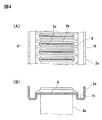
- FIG. 4 is a plan view of the conventional core plate (A) and a sectional view taken along line BB of (A) in FIG.
- FIG. 1 is a front view of a main part of a heat exchanger tank having a core plate of the present invention
- FIG. 2A is a cross-sectional view of a main part of the II-II arrow view of FIG. 2 (B) is a cross-sectional view taken along the line BB of FIG. 2 (C) of the core plate 2
- FIG. 2 (C) is a plan view of a main part of the core plate 2.
- this heat exchanger tank can be used as a radiator for engine cooling water. Then, as shown in FIG.
- Each tank is composed of an elongated tank body 1 having an opening on the opposite side of the bottom surface of the tank and a core plate 2 that closes the opening.
- the small flange portion at the open end of the tank body 1 is fitted into the annular groove of the core plate 2 via the seal 10, and the claw portion 8 provided at the edge portion of the core plate 2 is crimped to form the tank. It is formed. As shown in FIGS.
- the flat surface of the core plate 2 has an annular groove 7 formed on the outer periphery thereof.
- a large number of flat holes 3 located on the major axis 3a in the width direction of the core plate 2 are formed in parallel at regular intervals in the longitudinal direction of the core plate 2, and the edges thereof project toward the inner surface of the tank. Is subjected to burring processing 6. Both ends of the flat tube 4 are inserted into the flat holes 3 of each tank, and the insertion portions are brazed and fixed.
- the ribs 5 are arranged in a straight line between the flat holes 3.
- the rib 5 reaches the annular groove of the core plate 2 at an intermediate position between the adjacent flat holes 3 of the core plate 2, parallel to the flat holes 3 and longer than the flat holes 3, and is also the outer surface of the core plate 2. It protrudes to the side and is continuous. Further, in the rib 5, an intermediate rib 5a formed at a shallow t1 with respect to the root of the burring process 6 is formed at an intermediate position in the longitudinal direction of the flat hole 3, and the rib 5 has a t2 deeper than the intermediate rib 5a at both ends.
- the formed end rib 5b is formed (see FIG. 2B). Further, in this example, as shown in FIG. 3, hem portions are formed along the rib 5 on both sides of the rib 5. As shown in FIG.
- a narrow portion 5c formed in a narrow d1 is formed in the hem portion at an intermediate position in the longitudinal direction of the flat hole 3, and at both end positions of the flat hole 3, the hem portion is formed.
- a wide portion 5d formed in a wide d2 is formed.
- the relationship between the narrow portion 5c of the hem portion and the wide portion 5d is that the width of the narrow portion 5c ⁇ the width of the wide portion 5d.
- the core plate 2 of the present invention absorbs stress generated in response to expansion and contraction of the flat tube 4 while maintaining pressure resistance due to the above-mentioned configuration of the rib 5.
- the core plate 2 of this embodiment by having the intermediate ribs 5a formed shallowly and the end ribs 5b formed deeply, sufficient rigidity is ensured in the ribs 5b at both ends, and the intermediate portion is provided. It is suppressed that the rigidity of the rib 5a is excessive.
- the narrow portion 5c at the intermediate position in the longitudinal direction of the flat hole 3 and the wide portion 5d at the positions of both ends sufficient rigidity is ensured in the wide portion 5d at both ends.
- the rigidity of the narrow portion 5c at the intermediate position becomes excessive. That is, due to the synergistic effect of the relationship between the intermediate rib 5a and the end rib 5b of the rib 5 and the relationship between the narrow portion 5c and the wide portion 5d, the flat tube 4 at the joint between the core plate 2 and the flat tube 4 It is possible to both relax the stress concentration at both ends in the width direction of the flat tube 4 and suppress the stress increase over the entire width direction of the flat tube 4.
- the core plate 2 in which the intermediate ribs 5a and the end ribs 5b are formed and the narrow portion 5c and the wide portion 5d are formed is exemplified.
- the form of the intermediate rib 5a and the end rib 5b, and the form of the narrow portion 5c and the wide portion 5d can be independently adopted for the core plate 2. That is, the core plate 2 in which only the intermediate rib 5a and the end rib 5b shown in FIG. 1 are formed may be used. Further, the core plate 2 in which only the narrow portion 5c and the wide portion 5d shown in FIG. 2 are formed may be used. Further, regarding the form of the core plate 2 in which the intermediate rib 5a and the end rib 5b are formed, as shown in FIG. 2B, the rib 5 has a cross section parallel to the long axis 3a of the flat hole 3.
- the middle portion of the ridgeline can be formed so as to project in a chevron shape toward the inner surface side of the tank with respect to both ends.
Landscapes
- Engineering & Computer Science (AREA)
- Physics & Mathematics (AREA)
- Thermal Sciences (AREA)
- Mechanical Engineering (AREA)
- General Engineering & Computer Science (AREA)
- Geometry (AREA)
- Details Of Heat-Exchange And Heat-Transfer (AREA)
- Heat-Exchange Devices With Radiators And Conduit Assemblies (AREA)
Priority Applications (1)
| Application Number | Priority Date | Filing Date | Title |
|---|---|---|---|
| JP2021514252A JP7511545B2 (ja) | 2019-04-15 | 2020-04-13 | 熱交換器用タンクのコアプレート |
Applications Claiming Priority (2)
| Application Number | Priority Date | Filing Date | Title |
|---|---|---|---|
| JP2019-076834 | 2019-04-15 | ||
| JP2019076834 | 2019-04-15 |
Publications (1)
| Publication Number | Publication Date |
|---|---|
| WO2020213738A1 true WO2020213738A1 (ja) | 2020-10-22 |
Family
ID=72837392
Family Applications (1)
| Application Number | Title | Priority Date | Filing Date |
|---|---|---|---|
| PCT/JP2020/016983 Ceased WO2020213738A1 (ja) | 2019-04-15 | 2020-04-13 | 熱交換器用タンクのコアプレート |
Country Status (2)
| Country | Link |
|---|---|
| JP (1) | JP7511545B2 (https=) |
| WO (1) | WO2020213738A1 (https=) |
Citations (4)
| Publication number | Priority date | Publication date | Assignee | Title |
|---|---|---|---|---|
| JPH01170887U (https=) * | 1988-05-17 | 1989-12-04 | ||
| JPH0346776U (https=) * | 1989-08-30 | 1991-04-30 | ||
| US20160187077A1 (en) * | 2013-09-04 | 2016-06-30 | Mahle International Gmbh | Tube sheet |
| JP2017075741A (ja) * | 2015-10-15 | 2017-04-20 | 株式会社デンソー | 熱交換器 |
-
2020
- 2020-04-13 JP JP2021514252A patent/JP7511545B2/ja active Active
- 2020-04-13 WO PCT/JP2020/016983 patent/WO2020213738A1/ja not_active Ceased
Patent Citations (4)
| Publication number | Priority date | Publication date | Assignee | Title |
|---|---|---|---|---|
| JPH01170887U (https=) * | 1988-05-17 | 1989-12-04 | ||
| JPH0346776U (https=) * | 1989-08-30 | 1991-04-30 | ||
| US20160187077A1 (en) * | 2013-09-04 | 2016-06-30 | Mahle International Gmbh | Tube sheet |
| JP2017075741A (ja) * | 2015-10-15 | 2017-04-20 | 株式会社デンソー | 熱交換器 |
Also Published As
| Publication number | Publication date |
|---|---|
| JPWO2020213738A1 (https=) | 2020-10-22 |
| JP7511545B2 (ja) | 2024-07-05 |
Similar Documents
| Publication | Publication Date | Title |
|---|---|---|
| WO2017064940A1 (ja) | 熱交換器 | |
| US20180187985A1 (en) | Heat exchanger and associated method for producing same | |
| JP6421781B2 (ja) | 熱交換器 | |
| WO2021049505A1 (ja) | 熱交換器のタンク構造 | |
| WO2020213738A1 (ja) | 熱交換器用タンクのコアプレート | |
| JP2012247093A (ja) | ヘッダプレートレス熱交換器用偏平チューブ | |
| TWI586933B (zh) | A condenser with an additional flank configuration | |
| WO2021054484A1 (ja) | 熱交換器の偏平チューブとヘッダプレートのろう付構造 | |
| JP6221727B2 (ja) | シリンダヘッド構造 | |
| KR102252235B1 (ko) | 열교환기 | |
| WO2013161240A1 (ja) | フィンチューブ熱交換器 | |
| WO2022014719A1 (ja) | 熱交換器のヘッダプレート構造 | |
| WO2019163973A1 (ja) | 熱交換器のタンク構造 | |
| JP2018515737A (ja) | 特に自動車両用の熱交換器のためのコレクタプレート | |
| WO2014073413A1 (ja) | シリンダヘッドガスケット | |
| JP7244439B2 (ja) | ヘッダープレートレス型熱交換器 | |
| JP6972947B2 (ja) | フィンチューブ熱交換器 | |
| JP2022060112A (ja) | 熱交換器のヘッダプレート構造 | |
| JP7556702B2 (ja) | 熱交換器のタンク構造 | |
| JP2022060111A (ja) | 熱交換器のヘッダプレート構造 | |
| JP2021042925A5 (https=) | ||
| JP6276114B2 (ja) | ヘッダプレートレス熱交換器用偏平チューブ | |
| KR101280620B1 (ko) | 라디에이터 결합구조 | |
| JP2014077365A (ja) | ガスケット | |
| KR102808792B1 (ko) | 열교환기 |
Legal Events
| Date | Code | Title | Description |
|---|---|---|---|
| 121 | Ep: the epo has been informed by wipo that ep was designated in this application |
Ref document number: 20791843 Country of ref document: EP Kind code of ref document: A1 |
|
| ENP | Entry into the national phase |
Ref document number: 2021514252 Country of ref document: JP Kind code of ref document: A |
|
| NENP | Non-entry into the national phase |
Ref country code: DE |
|
| 122 | Ep: pct application non-entry in european phase |
Ref document number: 20791843 Country of ref document: EP Kind code of ref document: A1 |