WO2020213633A1 - 培養装置、担体支持装置、および培養対象の製造方法 - Google Patents
培養装置、担体支持装置、および培養対象の製造方法 Download PDFInfo
- Publication number
- WO2020213633A1 WO2020213633A1 PCT/JP2020/016539 JP2020016539W WO2020213633A1 WO 2020213633 A1 WO2020213633 A1 WO 2020213633A1 JP 2020016539 W JP2020016539 W JP 2020016539W WO 2020213633 A1 WO2020213633 A1 WO 2020213633A1
- Authority
- WO
- WIPO (PCT)
- Prior art keywords
- carrier
- culture
- culture solution
- unit
- fiber
- Prior art date
- Legal status (The legal status is an assumption and is not a legal conclusion. Google has not performed a legal analysis and makes no representation as to the accuracy of the status listed.)
- Ceased
Links
Images







Classifications
-
- C—CHEMISTRY; METALLURGY
- C12—BIOCHEMISTRY; BEER; SPIRITS; WINE; VINEGAR; MICROBIOLOGY; ENZYMOLOGY; MUTATION OR GENETIC ENGINEERING
- C12M—APPARATUS FOR ENZYMOLOGY OR MICROBIOLOGY; APPARATUS FOR CULTURING MICROORGANISMS FOR PRODUCING BIOMASS, FOR GROWING CELLS OR FOR OBTAINING FERMENTATION OR METABOLIC PRODUCTS, i.e. BIOREACTORS OR FERMENTERS
- C12M1/00—Apparatus for enzymology or microbiology
-
- C—CHEMISTRY; METALLURGY
- C12—BIOCHEMISTRY; BEER; SPIRITS; WINE; VINEGAR; MICROBIOLOGY; ENZYMOLOGY; MUTATION OR GENETIC ENGINEERING
- C12N—MICROORGANISMS OR ENZYMES; COMPOSITIONS THEREOF; PROPAGATING, PRESERVING, OR MAINTAINING MICROORGANISMS; MUTATION OR GENETIC ENGINEERING; CULTURE MEDIA
- C12N1/00—Microorganisms; Compositions thereof; Processes of propagating, maintaining or preserving microorganisms or compositions thereof; Processes of preparing or isolating a composition containing a microorganism; Culture media therefor
-
- C—CHEMISTRY; METALLURGY
- C12—BIOCHEMISTRY; BEER; SPIRITS; WINE; VINEGAR; MICROBIOLOGY; ENZYMOLOGY; MUTATION OR GENETIC ENGINEERING
- C12N—MICROORGANISMS OR ENZYMES; COMPOSITIONS THEREOF; PROPAGATING, PRESERVING, OR MAINTAINING MICROORGANISMS; MUTATION OR GENETIC ENGINEERING; CULTURE MEDIA
- C12N1/00—Microorganisms; Compositions thereof; Processes of propagating, maintaining or preserving microorganisms or compositions thereof; Processes of preparing or isolating a composition containing a microorganism; Culture media therefor
- C12N1/12—Unicellular algae; Culture media therefor
Definitions
- the present invention relates to a culture device, a carrier support device, and a method for producing a culture target.
- Microalgae such as chlorella and microorganisms such as photosynthetic bacteria are highly promising as resources capable of producing energy without emitting CO 2 and other industrially usable resources, and can be utilized and efficiently at the commercial level. There are high expectations for such production.
- microalgae In order to use microalgae for energy resources and other industrial uses, it is required to produce them at the lowest possible cost.
- a culture system for microalgae a system for culturing a large amount of microalgae in water using a large-scale pool or tank is known.
- oil is produced by absorbing light, taking in carbon dioxide, and performing photosynthesis as photosynthetic microalgae in a culture tank (or culture pond) containing a mixed solution of photosynthetic microalgae and a culture solution.
- Photosynthetic microalgae that have produced oil are collected in a floating state by means of recovery means, and as a result, the amount of culture solution associated with the cultured photosynthetic microalgae is significantly reduced.
- a photosynthetic microalgae culture apparatus is disclosed.
- an object of the present invention is to provide a culture apparatus or the like capable of improving the efficiency of culture.
- the technique disclosed herein is a culture apparatus comprising a carrier through which the culture solution flows down the surface and / or inside, and a supply unit for supplying the culture solution to the carrier.
- the carrier has a plurality of first fibers arranged in a direction along the vertical direction and a plurality of second fibers arranged in a direction intersecting the vertical direction, and the culture solution in the direction along the second fibers.
- the diffusion rate is a culture apparatus in which the carrier is arranged in a direction in which the second fiber is arranged in the vertical direction, and the diffusion rate is faster than the diffusion rate of the culture solution in the direction along the first fiber.
- the first fiber and the second fiber each have a curved portion, and the number of curved portions of the first fiber is larger than that of the curved portion of the second fiber. Further, the first fiber and the second fiber each have a curved portion, and the curved portion of the first fiber may have a smaller radius of curvature than the curved portion of the second fiber.
- the carrier may be formed by laminating a fiber layer formed by the plurality of first fibers and the plurality of second fibers. Further, it is preferable that the first fiber and the second fiber can transmit at least a part of the light applied to the carrier. Further, it is preferable that the carrier is suspended from the culture device and is more easily stretched in the direction along the first fiber than in the direction along the second fiber.
- the technique disclosed herein is a culture apparatus comprising a carrier through which the culture solution flows down the surface and / or inside, and a supply unit for supplying the culture solution to the carrier.
- the carrier has a plurality of first fibers arranged in a direction along the vertical direction and a plurality of second fibers arranged in a direction intersecting the vertical direction, and the carrier is suspended in the culture apparatus.
- the culture device is provided so that the direction along the first fiber is easier to stretch than the direction along the second fiber.
- the techniques disclosed herein include a step in which the culture solution flows down the surface and / or inside of the carrier and a step in which the culture solution is supplied to the carrier.
- FIG. 1 It is a schematic block diagram which shows the culture system which concerns on this embodiment. It is a perspective view of a carrier. It is a schematic block diagram of a carrier unit. It is sectional drawing in IV-IV of FIG. It is an enlarged view in the region V of FIG. (A) to (d) are diagrams for explaining the conditions of Experiments 1 to 4. It is a table which shows the yield in Experiments 1 to 4. It is a flowchart explaining the operation of the manufacturing method of a microorganism in a culture system. It is a figure explaining the modification in this embodiment. It is a figure explaining the modification in this embodiment. It is a figure explaining the modification in this embodiment. It is a figure explaining the modification in this embodiment. (A) and (b) are schematic block diagrams of carriers in other embodiments.
- (A) to (c) are diagrams for explaining a dropping test of a carrier.
- (A) to (c) are diagrams for explaining the tensile test of the carrier. It is a flowchart explaining the sterilization process in a culture system. It is a graph which shows the growth curve of chlorella quesleri 11h on a cotton cloth carrier.
- FIG. 1 is a schematic configuration diagram showing a culture system 1 according to the present embodiment.
- FIG. 1 a schematic configuration of the culture system 1 to which the present embodiment is applied will be described.
- the culture system 1 which is an example of the culture apparatus is a culture in which a carrier unit 10 to which a culture solution containing microorganisms is supplied, a culture unit 30 for culturing microorganisms, and a culture solution containing microorganisms are circulated.
- Each configuration includes a liquid circulation unit 50, a gas supply unit 60 that supplies gas to the carrier unit 10, a carrier irradiation unit 70 that irradiates the carrier unit 10 with light, and a culture irradiation unit 80 that irradiates the culture unit 30 with light. It has a control unit 90 that controls the members.
- the vertical direction of the culture system 1 shown in FIG. 1 may be simply referred to as the vertical direction.
- the width direction of the culture system 1 may be simply referred to as the width direction.
- the direction intersecting the vertical direction and the width direction in the culture system 1 may be simply referred to as the depth direction.
- the carrier unit 10 has a carrier 12 to which a culture solution containing microorganisms is supplied, a cover 15 that covers the outer periphery of the carrier 12, and a support 17 that supports the carrier 12 and the cover 15.
- a plurality (two) of carriers 12 housed in the cover 15 are provided side by side in the depth direction.
- the culture solution containing the microorganisms flows down along the carrier 12, and is irradiated with light and supplied with carbon dioxide gas. Details of the carrier unit 10 will be described later.
- the culture unit 30, which is an example of the culture unit, includes a culture tank 31 in which the culture solution is stored and the microorganisms are cultured, a stirrer 35 for stirring the culture solution in the culture tank 31, and filtration for filtering the cultured microorganisms. It has a vessel 37.
- the culture tank 31 is a container in which the upper side in the vertical direction is open. In the culture tank 31, the stored culture solution can come into contact with the outside air. That is, the culture tank 31 has an opening for taking in the outside air.
- the culture tank 31 is made of a resin, glass, or the like that is transparent to the light emitted by the culture irradiation unit 80. That is, the side surface of the culture tank 31 functions as a passage region for passing light toward the culture solution.
- the stirrer 35 which is an example of the stirring unit, stirs the culture solution in the culture tank 31 by rotating a rotor (not shown) provided in the culture tank 31.
- the stirrer 35 is not limited to the configuration using a rotor as long as it is possible to stir the culture solution in the culture tank 31.
- the culture solution may be agitated by supplying a gas such as carbon dioxide gas or a liquid such as a culture solution into the culture tank 31.
- the culture solution may be agitated by vibrating the culture tank 31 by, for example, ultrasonic waves.
- the filter 37 receives the cultured microorganisms from the culture tank 31 together with the culture solution. Then, the filter 37 recovers the microorganisms by separating the microorganisms from the culture solution by filtration.
- the culture solution from which the microorganisms have been separated by the filter 37, that is, the filtrate may be discarded, or may be supplied to the culture tank 31 and used again for culturing the microorganisms.
- the culture solution circulation unit 50 which is an example of the supply unit, receives the culture solution from the first pipe 51 that supplies the culture solution to the carrier unit 10, the second pipe 53 that collects the culture solution from the carrier unit 10, and the culture tank 31. It has a third pipe 57 for circulation and a pump 59 as a driving source for circulating the culture solution.
- the culture solution circulation unit 50 supplies the microorganisms and the culture solution from the culture tank 31 to the carrier unit 10 by the pump 59, and repeatedly collects the microorganisms together with the culture solution from the carrier unit 10 to the culture tank 31, thereby forming the microorganisms and the culture solution. Circulate the culture medium.
- the illustrated culture unit 30 is arranged at a position deviated from the lower side in the vertical direction of the carrier unit 10. That is, the culture unit 30 is provided at a different point from the carrier unit 10.
- the carrier unit 10 and the culture unit 30 provided at different points and separated from each other are connected to each other by the first pipe 51, the second pipe 53, and the third pipe 57.
- the gas supply unit 60 which is an example of the gas supply unit, has a gas cylinder 61 for compressing and accommodating carbon dioxide gas, and a gas pipe 63 for supplying carbon dioxide gas supplied from the gas cylinder 61 to the carrier unit 10.
- the carrier irradiation unit 70 which is an example of the irradiation unit, has a first irradiation panel 71 and a second irradiation panel 73 that irradiate the carrier unit 10 with light from both sides in the depth direction with the carrier unit 10 interposed therebetween.
- the first irradiation panel 71 and the second irradiation panel 73 have a substantially plate-like shape that is arranged to face the carrier unit 10.
- the first irradiation panel 71 and the second irradiation panel 73 for example, have a fluorescent lamp, an organic EL, an LED, or the like arranged as a light source, and are configured to irradiate light having a wavelength and a light amount suitable for the growth of microorganisms. There is.
- the wavelength of the light emitted by the first irradiation panel 71 and the second irradiation panel 73 is, for example, in the range of 380 to 780 nm. Further, it is preferable that the first irradiation panel 71 and the second irradiation panel 73 can irradiate only red light, for example, with respect to microorganisms capable of growing only with red light.
- the culture irradiation unit 80 which is an example of another irradiation unit, has a first irradiation panel 81 and a second irradiation panel 83 that irradiate light toward the carrier unit 10 from both sides in the depth direction across the culture tank 31.
- the first irradiation panel 81 and the second irradiation panel 83 are configured in the same manner as the first irradiation panel 71 and the second irradiation panel 73.
- the first irradiation panel 81 and the second irradiation panel 83 have a fluorescent lamp, an organic EL, an LED, or the like arranged as a light source, and irradiate light having a wavelength and a light amount suitable for the growth of microorganisms. It is configured as follows.
- the wavelength of the light emitted by the first irradiation panel 81 and the second irradiation panel 83 is, for example, in the range of 380 to 780 nm. Further, it is preferable that the first irradiation panel 81 and the second irradiation panel 83 can irradiate only red light, for example, to microorganisms capable of growing only with red light.
- the first irradiation panel 81 and the second irradiation panel 83 have a substantially plate-like shape that is arranged so as to face the carrier unit 10, but if the culture tank 31 can be irradiated with light, for example, in the vertical direction.
- the structure is not particularly limited, such as irradiating only from the upper side.
- the control unit 90 is configured by a computer or the like and controls the constituent members of the culture system 1. For example, the control unit 90 controls the operation timing of the culture solution circulation unit 50.
- microorganisms are cultivated in the culture unit 30. Then, while the culture solution containing the microorganism is circulated by the culture solution circulation unit 50, the carrier unit 10 supplies carbon dioxide gas to the microorganism and the culture solution and irradiates the culture solution with light. That is, in the carrier unit 10, carbon dioxide gas and light energy necessary for microorganisms to perform photosynthesis are supplied. Then, the microorganism and the culture solution are guided to the culture unit 30 again, and the microorganism is cultured in the culture unit 30. Further, in the culture unit 30, the culture of microorganisms is promoted by irradiating the culture irradiation unit 80 with light.
- the time required for the culture solution to pass through the culture unit 30 is longer than the time required for the culture solution to pass through the carrier unit 10.
- the time for the culture solution to be stored in the culture tank 31 is longer than the time for the culture solution to flow down the carrier 12.
- the amount of the culture solution stored in the culture tank 31 is larger than the amount of the culture solution existing in the cover 15.
- the microorganism to be cultured is, for example, a photosynthetic microorganism such as a photosynthetic bacterium or a photosynthetic microalgae.
- the culture system 1 does not have to include the carrier irradiation unit 70 and the culture irradiation unit 80.
- the culture solution is not particularly limited as long as it is a diluted solution of a medium capable of culturing microalgae by a usual method to increase the concentration of microorganisms.
- a general inorganic medium such as CHU medium, JM medium, or MDM medium can be used.
- diluted solutions of various media such as Gambog B5 medium, BG11 medium, and HSM medium are preferable.
- antibiotics and the like that do not affect the growth of microalgae may be added to the medium.
- the pH of the medium is preferably 4-10.
- wastewater discharged from various industries may be used.
- FIG. 2 is a perspective view of the carrier 12.
- FIG. 3 is a schematic configuration diagram of the carrier unit 10.
- the carrier unit 10 has a carrier 12, a cover 15, and a support 17.
- each configuration will be described.
- the carrier 12 is a plate-shaped member through which a culture solution containing microorganisms passes.
- the illustrated carrier 12 is a cloth member having a substantially rectangular front view. More specifically, the carrier 12 is composed of a flexible member, more specifically, a resin fiber such as polyester. Further, the illustrated carrier 12 is formed of a filamentous member that transmits at least a part of the light emitted from the first irradiation panel 71 and the second irradiation panel 73.
- the material of the carrier 12 is not particularly limited, and cotton, silk, hair, acrylic, or the like may be used.
- the carrier 12 has a warp 126 arranged along the longitudinal direction of the carrier 12 and a plurality of weft threads 127 arranged along a direction (width direction) intersecting the longitudinal direction of the carrier 12.
- a plurality of warp threads 126 are provided at predetermined intervals in the width direction.
- a plurality of weft threads 127 are provided at predetermined intervals in the longitudinal direction. Therefore, the carrier 12 can be regarded as a net body formed in a mesh shape.
- a plurality of openings 128 are formed in the carrier 12. The details will be described later, but the opening 128 has a size that allows microorganisms to pass through. Further, the opening 128 can be regarded as a through hole penetrating in the thickness direction of the carrier 12. Further, at least one of the warp 126 and the weft 127 may be a so-called wavy fiber member having a plurality of curved portions.
- the carrier 12 is provided in the carrier unit 10 by being bent in two at substantially the center in the longitudinal direction (see FIG. 1).
- the size of the carrier 12 is not particularly limited, but is formed large in order to culture the microorganism more efficiently.
- the carrier 12 is abbreviated in the longitudinal direction so as to have a vertical dimension of about 1.25 m by using a cloth member having a length of 2.5 m in the longitudinal direction and a length of 1 m in the width direction when unfolded. Folded in the center.
- irregularities and pores may be provided on the surface of the carrier 12.
- the “loading amount of microorganisms per 1 m 2 of carrier” means the loaded amount of microorganisms per 1 m 2 of surface area assuming that the surface of the carrier is a smooth flat surface, and forms irregularities and pores. It does not mean the actual surface area in consideration of the increase in surface area due to the above.
- the cover 15 As shown in FIG. 1, the cover 15 is formed by bending the center of the flexible sheet member in the longitudinal direction.
- the cover 15 is made of a material that transmits light emitted from the carrier irradiation unit 70.
- the cover 15 is made of a synthetic resin such as vinyl chloride, polyethylene, polyester, polypropylene, or PET.
- the cover 15 is formed in a flat bag shape capable of accommodating the carrier 12 inside. Further explaining, the cover 15 is formed so that the inside can be sealed except for a part. Specifically, the cover 15 shown in FIG. 3 has an outlet 154 for leading out the culture solution, an introduction port 156 for introducing the culture solution, and a gas port 157 for introducing carbon dioxide gas.
- the outlet 154 is provided at the lower end portion 152, which is the lower end portion in the vertical direction of the cover 15.
- the second pipe 53 can be attached to and detached from the outlet 154.
- the introduction port 156 is provided on the upper side of the cover 15 in the vertical direction.
- the end portion of the cover support 171 described later penetrates through the introduction port 156.
- the gas port 157 is provided at the central portion in the vertical direction of the cover 15. The end of the gas supply pipe 177, which will be described later, penetrates the gas port 157.
- the support 17 as an example of the support portion includes a cover support 171 that supports the cover 15, a carrier support 173 that supports the carrier 12, and a gas supply pipe 177 that supplies carbon dioxide gas. , A cover support 171, a carrier support 173, and a frame 179 that supports the gas supply pipe 177.
- the support 17 is formed of a material such as aluminum that does not interfere with the culture of microorganisms.
- the cover support 171 is a cylindrical member extending in the width direction.
- the cover 15 is hung on the cover support 171.
- the cover support 171 is formed with culture solution discharge holes 175 at predetermined intervals in the width direction.
- the culture solution discharge hole 175 is formed on the lower surface of the cover support 171 in the vertical direction.
- the culture solution discharge hole 175 discharges the culture solution from the inside of the cover support 171.
- one end of the cover support 171 protrudes from the introduction port 156 and is connected to the first pipe 51.
- the other end of the cover support 171 is connected to a pipe (not shown). This pipe guides the culture solution that was not supplied to the carrier 12 to the culture tank 31.
- the carrier support 173 is a columnar member extending in the width direction.
- the carrier support 173 is provided so as to be suspended from the cover support 171 on the lower side in the vertical direction with respect to the cover support 171.
- the carrier support 173 is a portion on which the bent carrier 12 is hung.
- the carrier support 173 in the illustrated example has a smaller dimension (outer diameter) in the depth direction than the cover support 171 (see FIG. 4 described later).
- the gas supply pipe 177 is a cylindrical member extending in the width direction.
- a plurality of gas discharge holes 178 are formed on the outer periphery of the gas supply pipe 177.
- the gas discharge hole 178 which is an example of the supply port, is open toward both sides in the vertical direction and both sides in the width direction.
- the gas discharge hole 178 discharges carbon dioxide gas from the inside of the gas supply pipe 177.
- the end of the gas supply pipe 177 protrudes from the gas port 157 and is connected to the gas pipe 63.
- the gas supply pipe 177 in the illustrated example has a smaller dimension (outer diameter) in the depth direction than the carrier support 173 (see FIG. 4 described later).
- the portion of the culture system 1 other than the carrier 12 can be regarded as a carrier support device.
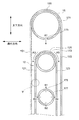
- FIG. 4 is a cross-sectional view taken along the line IV-IV of FIG.
- FIG. 5 is an enlarged view in the region V of FIG.
- FIGS. 3 to 5 the structure around the carrier 12 in the carrier unit 10 will be described with reference to FIGS. 3 to 5.
- the cover 15 is hung on the cover support 171 and arranged.
- the cover 15 has a first portion 151 and a second portion 153 located across a bent portion 155, which is an example of a continuous portion.
- the first part 151 and the second part 153 are respectively provided upright in the vertical direction.
- the carrier 12 is hung on the carrier support 173 and arranged.
- the carrier 12 has a shape having a first portion 121 and a second portion 123, which are examples of a flat plate portion, with a bent portion 125, which is a bent and curved portion, interposed therebetween.
- the first part 121 and the second part 123 are provided upright in the vertical direction, respectively.
- the first part 121 and the second part 123 are arranged apart from each other.
- the first part 121 and the second part 123 are arranged apart from the cover 15.
- the first part 121 and the second part 123 are examples of the first facing portion and the second facing portion.
- the culture solution discharge hole 175 of the cover support 171 is located on the upper side of the bent portion 125 of the carrier 12 in the vertical direction. That is, the culture solution discharge hole 175, which is an example of another supply port, opens toward the bent portion 125. Further, a gas supply pipe 177 is arranged between the first part 121 and the second part 123 of the carrier 12. The gas discharge hole 178 of the gas supply pipe 177 opens toward the space sandwiched by the first part 121 and the second part 123.
- the culture solution discharged from the culture solution discharge hole 175 is supplied to the bent portion 125 of the carrier 12 (see arrow A1 in the figure).
- the culture solution supplied to the bent portion 125 branches into the first portion 121 and the second portion 123 and flows down (see arrows A3 and A5 in the figure).
- the carbon dioxide gas discharged from the gas discharge hole 178 is supplied into the space sandwiched by the first part 121 and the second part 123 of the carrier 12 (see arrows B1 to B4 in the figure). At this time, a part of the carbon dioxide gas flows in the vertical direction (see arrows B1 and B2 in the figure), and a part of the carbon dioxide gas flows in the depth direction, that is, toward the first part 121 and the second part 123 (arrows B3 and B2 in the figure). See B4).
- the flow of the culture solution and the like in the carrier 12 will be described in detail with reference to FIG.
- the culture solution flows from the upper side to the lower side in the vertical direction (see arrow A7 in the figure).
- carbon dioxide gas passes through Part 1 121 along the depth direction (see arrow B5 in the figure). This flow of carbon dioxide gas intersects with the flow of the culture solution (see arrow A7 in the figure). Further, carbon dioxide gas flows from the lower side in the vertical direction to the upper side (see arrow B6 in the figure). The flow of this carbon dioxide gas is in the opposite direction to the culture solution, that is, in the direction facing the culture solution. In this way, the amount of carbon dioxide gas supplied to the culture solution can be increased by flowing the carbon dioxide gas in the direction intersecting the culture solution and in the direction opposite to the culture solution.
- the light emitted from the second irradiation panel 73 passes through the first part 121 along the depth direction (see arrow C1 in the figure).
- the traveling direction of this light is the direction intersecting with the culture solution. As a result, the amount of light received by the microorganisms contained in the culture solution can be increased.
- the microorganisms flow down together with the culture solution from the upper side in the vertical direction to the lower side. That is, in the initial stage of starting the flow of the culture solution, the microorganisms fall along the warp 126.
- the microorganisms that fall along the warp 126 change their flow direction when they hit the weft 127 (arrows A11, A13, A15, A17 in the figure). That is, the microorganisms fall while swinging in the depth direction. More specifically, the microorganisms fall while passing through the opening 128 of the carrier 12. This prolongs the time that the microorganisms come into contact with the gas, and as a result, the gas exchange efficiency of the microorganisms increases.
- the weft threads 127 are molded in a wavy shape, and the weft threads 127 are arranged so as to be displaced from each other in the depth direction. This further promotes the fluctuation of microorganisms in the depth direction. As a result, the growth of microorganisms on the carrier is promoted.
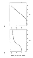
- FIG. 17 showing the results of Example 2 is a growth curve of chlorella cells on a cloth (corresponding to the carrier 12 of the present invention).
- the left figure (a) shows the amount of microorganisms on the vertical axis on a logarithmic scale
- the right figure (b) shows the amount on a linear scale.
- the straight part in the left figure represents exponential growth (logarithmic growth phase), and the straight part in the right figure represents the linear growth phase. Therefore, even on the carrier 12 in the production of the photosynthetic microorganism using the microbial culture system of the present invention, first logarithmic growth, then linear growth, and gradual growth approaching saturation, basically in a liquid medium. Take a growth curve similar to the suspension culture in.
- the cells adhering to or staying on the carrier 12 hardly move, so that the cells located on the surface continue to receive light. Therefore, it is composed of a cell group having a different environment from the inner cell group located between the surface cell group that continues to receive light and the carrier 12 and located behind the surface cell group. That is, the cells of the cell group on the surface layer are cells that retain the proliferative ability of logarithmic growth. This point is different from the cells in liquid culture in which the cell concentration has increased and the cells have entered the linear growth phase.
- the microbial culture system of the present invention to photosynthetic microorganisms, even when the amount of cells attached to the carrier 12 is increased, the cells of the cell group on the surface layer have the ability to proliferate in logarithmic growth. Can be retained. Therefore, when the expected production amount per day (dry weight gDW) is P (gDW / m 2 ) and the daily proliferative capacity of cells during logarithmic growth (expressed as a magnification per unit period) is ⁇ times.
- the initial cell mass C 0 (gDW / m 2 ) of the day is P ⁇ C 0 ⁇ ( ⁇ -1), the following formula (1) C 0 ⁇ P / ( ⁇ -1) ⁇ ⁇ ⁇ (1) ( ⁇ is the specific growth rate, sometimes expressed per hour).
- P is, for example, 5 g / m 2 or more, 6 g / m 2 or more, 7 g / m 2 or more, 8 g / m 2 or more, 9 g / m 2 or more, 10 g / m 2 or more, 15 g / m 2 or more
- the initial cell mass C 0 can be set to be 20 g / m 2 or more.
- the upper limit of P is not particularly limited, in order to ensure a sufficient quantity for superficial cells of the carrier 12, is preferably 300 g / m 2 or less, more preferably 100 g / m 2 or less, is 50 g / m 2 or less More preferred.
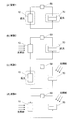
- FIG. 6 (a) to 6 (d) are diagrams for explaining the conditions of Experiments 1 to 4.
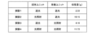
- FIG. 7 is a table showing the yields in Experiments 1 to 4.
- Spirulina was cultivated using the culture system 1 as shown in FIG.
- the carrier 12 a nylon mesh material, a so-called nylon towel (manufactured by Lifelex), was used.
- the dimensions of the carrier 12 were 18 cm in width and 100 cm in length.
- the carrier 12 was measured using two pieces hung in half.
- the cover 15 used two vinyl chloride sheets having a thickness of 0.45 mm and each accommodated the carrier 12.
- the culture solution discharge holes 175 of the cover support 171 had a diameter of 0.9 mm, and were provided at nine locations every 2 cm along the longitudinal direction of the cover support 171.
- the first irradiation panel 71, the second irradiation panel 73, the first irradiation panel 81, and the second irradiation panel 83 were irradiated with light using a red LED (manufactured by Effect). Light intensity was 20 ⁇ mol / m 2 / sec at the end of the carrier 12 50 ⁇ mol / m 2 / sec, in the center of the carrier 12.
- the Eheim amphibious pump 1048 was used as the pump 59.
- a silicon hose (10 ⁇ 13 mm) was used for the first pipe 51, the second pipe 53, and the third pipe 57.
- a Y-shaped connector AS ONE, 1-7377-18
- a flow path branching to the two cover supports 171 was secured in the first pipe 51.
- the culture tank 31 was made of polypropylene and had dimensions of 30 cm in width, 15 cm in depth, and 30 cm in height.
- the culture medium is as shown in Table 1.
- Experiments 1 to 4 were performed while changing the light irradiation conditions for the carrier unit 10 and the culture unit 30. Specifically, each of the carrier unit 10 and the culture unit 30 was switched between a case of irradiating light and a case of shielding light so as not to be irradiated. Further explaining, the light shielding of the carrier unit 10 was performed by covering the cover 15 of the carrier unit 10 with an aluminum foil. In addition, by blocking the light from the carrier unit 10, the light does not reach the carrier 12 of the carrier unit 10. Further, the light shielding of the culture unit 30 was performed by covering the culture tank 31 of the culture unit 30 with aluminum foil. In addition, by shading the culture unit 30, light does not reach the inside of the culture tank 31 of the culture unit 30.
- both the carrier unit 10 and the culture unit 30 were shielded from light.
- the carrier unit 10 was irradiated with light, and the culture unit 30 was shielded from light.
- the carrier unit 10 was shielded from light and the culture unit 30 was irradiated with light.
- both the carrier unit 10 and the culture unit 30 were irradiated with light.
- the culture targets to be cultivated by the culture system 1 are not only non-motile or poor photosynthetic microorganisms such as chlorella, cinecoquistis and spirulina, but also planktonic euglena, chlamydomonas and preurocrisis that move in water with flagella. Is also included.
- the microorganisms to be cultured in the culture system 1 are extremely diverse. Examples of the main microorganism groups to be cultured in the culture system 1 include the following classes A, B, and C.
- prokaryotic eubacteria and archaea can be mentioned.
- the eubacteria include non-oxygenated photosynthetic bacteria, cyanobacteria that perform oxygen-generating photosynthesis, facultative anaerobic and non-fermentative bacteria that utilize organic substances, and inorganic vegetative bacteria, actinomycetes, and corine bacteria.
- Umm spore-forming bacteria can be mentioned.
- Photosynthetic bacteria include Rhodobacter, Rhodospirillum, Chlorobium, and Chloroflexi.
- Cyanobacteria include Synechococcus, Synechococcus, Spirulina, Arsulospira, Nostock, Anabaena, Osilatoria, Lyngbya, Nostoc commune, Suizenji nori.
- facultative anaerobic fermenting bacteria include Escherichia coli and lactic acid bacteria.
- Pseudomonas is an example of a non-fermentative bacterium.
- Examples of inorganic vegetative bacteria include hydrogen bacteria. Streptomyces is an actinomycete, and Bacillus subtilis is an spore-forming bacterium.
- Archaea include thermophiles and halophilic bacteria.
- Thermophiles include Thermococcus and Haloarchaea include Haloarchaea.
- Other examples include glutamic acid-producing bacteria, lysine-producing bacteria, and cellulose-producing bacteria.
- microalgae which are eukaryotic photosynthetic microorganisms can be mentioned.
- Microalgae include green algae, treboxia algae, red algae, diatoms, haptophytes, true eye spot algae, Euglena, and brown algae.
- Green algae include Chlorella, Senedesmus, Chlamydomonas, Botryococcus, Hematococcus, Nannochloris, and Pseudocolycystis
- Treboxia algae include Parachlorella and Cocomixa.
- Red algae include Cyanidioschyzon, Cyanidium, Gardieria, and Porphyridium, and diatoms include Nitzschia, Feodactylum, Chaetoceros, Tarashioshira, Skelettonema, and Fitzlifera.
- Haptophytes include preurocrisis, gefirocapsa, emiliania, isochrysidales and pavlova.
- Euglena is a true eye alga
- Euglena is a euglena.
- symbiodinium is mentioned as a zooxanthellae which is a symbiotic alga of coral.
- Fungi include yeast and Aspergillus.
- hyphal culture of basidiomycetes is a culture target.
- Labyrinthula an aquatic fungus (currently a protist), can also be applied.
- Labyrinthulomy includes Aurantiochytrium.
- green algae such as sea lettuce and green laver
- red algae such as Pyropia tenera, Pyropia yezoensis, Pyropia yezoensis, and other edible seaweed are also targeted for cultivation.
- mosses which are green plants, are also targeted for culture.
- lichens which are symbiotic organisms, are also targeted for culture.
- microalgae can be regarded as containing cyanobacteria.
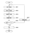
- FIG. 8 is a flowchart illustrating the operation of the method for producing a microorganism in the culture system 1.
- the method of culturing a microorganism executed in the culture system 1 as described above can be regarded as a method for producing a microorganism.
- a method for producing a microorganism executed in the culture system 1 will be described with reference to FIG.
- the carrier 12 of the carrier unit 10 is irradiated with light by the carrier irradiation unit 70 (S801). Further, in the carrier 12, carbon dioxide gas is supplied to the carrier by the gas supply unit 60 (S802).
- the culture irradiation unit 80 irradiates the culture solution containing the microorganism with light (S803). Further, in the culture tank 31 of the culture unit 30, the culture solution is stirred by the stirrer 35 (S804).
- the control unit 90 determines whether it is the timing to harvest the microorganisms in the predetermined culture tank 31 (S805).
- the microorganisms are harvested by filtering the microorganisms from the culture solution by the filter 37 (S806).
- the microorganism and the culture solution are sent to the carrier unit 10 by the culture solution circulation unit 50, so that the microorganism and the culture solution are circulated (S807).
- ⁇ Modification example> 9 to 11 are views for explaining a modification of the present embodiment. Next, a modification of the present embodiment will be described with reference to FIGS. 9 to 11. In the following description, the same parts as those described in the above embodiment are designated by the same reference numerals, and detailed description thereof will be omitted.
- the culture solution that has passed through the carrier unit 10 is collected in the culture unit 30 via the second pipe 53, but the culture solution that has passed through the carrier unit 10 is collected in the culture tank 31.
- the configuration is not particularly limited as long as it is recovered to.
- the culture unit 300 may be provided on the lower side in the vertical direction of the carrier unit 10.
- the culture unit 300 has a culture tank 310 that receives the culture solution and microorganisms that are discharged from the carrier unit 10 and fall.
- the culture tank 310 is a substantially cylindrical container.
- a plurality of irradiation bodies 85 of the culture irradiation unit 80 are arranged side by side on the outer periphery of the culture tank 310.
- the culture solution dropped from the carrier unit 10 is stored in the culture tank 310, and the microorganisms are cultured in the culture tank 310 by being irradiated with light from the irradiator 85.
- the culture irradiation unit 80 irradiates the culture unit 30 with light, but the configuration is not particularly limited as long as the culture unit 30 is irradiated with light.
- the culture unit 350 may be provided outdoors. That is, the culture tank 351 may be configured to receive sunlight and may not be provided with the culture irradiation unit 80. Further, unlike the drawing, it may be configured to receive sunlight and further to include a culture irradiation unit 80.
- the migratory pond method (pound method) is known as one of the culturing methods for microorganisms different from the present embodiment and the modified example.
- this migratory pond method since it can be expanded in the depth direction only within the reach of sunlight (water depth of about 30 cm), it is necessary to acquire a vast land in the horizontal direction.
- the culture system 103 since the microorganisms and the culture solution are irradiated with light in the carrier unit 10, the water depth of the culture tank 351 can be made deeper than the range where sunlight can reach.
- the culture tank 351 in the illustrated example is partially buried underground to secure the dimensions of the culture tank 351 in the depth direction. Further, the illustrated culture tank 351 is formed so that the maximum width of the stored culture solution on the liquid surface is larger than the maximum depth of the stored culture solution.
- the culture system 103 can be regarded as a hybrid culture system that combines the culture of the microorganism by the carrier method in the carrier unit 10 and the culture of the culture by the circulation pond method in the culture unit 305.
- a hybrid type microbial culture system that combines a carrier method and a culturing method for microorganisms other than the migratory pond may be used.
- it may be a hybrid type culturing system of microorganisms in which the culturing of microorganisms by the carrier method in the carrier unit 10 and the culturing of microorganisms by the so-called tank method are combined.
- the microorganism and the culture solution were irradiated with light and the carbon dioxide gas was supplied, but the microorganism and the culture solution were irradiated with light and carbon dioxide.
- the configuration is not particularly limited as long as the gas supply is performed.
- a tank 110 that stores the culture solution and executes light irradiation and carbon dioxide gas supply may be provided.
- an irradiation panel 75 as a light emitting source and a gas supply unit 65 for supplying carbon dioxide gas are provided.
- the microorganisms and the culture solution that have been irradiated with light and supplied with carbon dioxide in the carrier unit 10 are guided to the tank 110. Then, microorganisms are cultivated in this tank 110.
- the tank 110 is provided with the gas supply unit 65, but the tank 110 may not be provided with the gas supply unit 65.
- the cover 15 of the carrier unit 10 is provided for each carrier 12, but the present invention is not limited to this.
- a plurality of carriers 12 may be provided in one cover 15.
- the cover 15 for each carrier 12 it becomes easy to control the carbon dioxide gas supplied to each of the carriers 12.
- the culture system 1 may have a configuration in which the carrier unit 10 is not provided with the cover 15.
- the carrier 12 is bent in two and the bent portion 125 is hung on the support 17, but the present invention is not limited to this.
- the carrier 12 may be provided by suspending it in a flat plate shape.
- the carrier 12 may be formed in a shape other than a flat plate such as a cylinder or a square cylinder.
- the carrier 12 is a cloth member formed of fibers, but the material and shape are not limited to this.
- the carrier 12 may be a plate-shaped member having a plurality of through holes having a size that allows microorganisms to pass through.
- the culture unit 30 is irradiated with light, but the culture unit 30 may not be irradiated with light. Further explaining, for example, the culture tank 31 as a whole is provided underground or indoors without opening the upper part of the culture tank 31, and is not received by the carrier irradiation unit 70 or sunlight. May be good.
- the cover support 171 supplied the culture solution to the bent portion 125, but the present invention is not limited to this as long as the culture solution can be supplied to the carrier 12.
- a spray unit (not shown) which is configured as a separate body from the cover support 171 and sprays the culture solution is provided at a position facing each of the first part 121 and the second part 123, and is provided through the spray part.
- the culture solution may be supplied to the carrier 12.
- the gas supply pipe 177 is provided between the first part 121 and the second part 123, but if carbon dioxide gas is supplied to the carrier 12, it will be provided. Not limited.
- the gas supply pipe 177 may be provided at a position facing each of the first part 121 and the second part 123, and may be configured to blow carbon dioxide gas.
- the carrier 12 may be configured not to supply carbon dioxide gas.
- FIG. 12A and 12 (b) are schematic block diagrams of the carrier 120 in other embodiments.
- FIG. 12A is a diagram showing a cross section of the carrier 120 in the depth direction
- FIG. 12B is a diagram showing the structures of the warp 1260 and the weft 1270 constituting the carrier 120.
- FIG. 13 is a diagram illustrating the difference between the warp threads 1260 and the weft threads 1270.
- the carrier 120 is configured by laminating layer members 1290, which are cloth-like members.
- layer members 1290 which are cloth-like members.
- the culture solution flows from the upper side to the lower side in the vertical direction (see arrow A7 in the figure).
- carbon dioxide gas passes through each layer member 1290 along the depth direction (see arrow B5 in the figure).
- a space is formed between the layer members 1290. This can increase the amount of carbon dioxide gas supplied to the culture broth.
- the layer member 1290 is an example of a fiber layer.
- the carrier 120 (layer member 1290) is composed of warp threads 1260 and weft threads 1270.
- the warp 1260 and weft 1270 are resin fibers such as nylon.
- the warp 1260 and the weft 1270 are formed of a thread-like member capable of transmitting at least a part of the light emitted from the carrier irradiation unit 70 (see FIG. 1). This makes it possible for the light of the carrier irradiation unit 70 to reach each layer member 1290.
- an opening 1280 is formed between the warp 1260 and the weft 1270. By passing through the opening 1280, the light of the carrier irradiation unit 70 can reach each layer member 1290.
- carbon dioxide gas can pass through the opening 1280. As a result, carbon dioxide gas can be supplied to each of the layer members 1290 provided in a laminated manner.
- the warp 1260 which is an example of the first fiber, is formed by twisting a plurality of (7 in the illustrated example) warp fibers 1261.
- the weft 1270 which is an example of the second fiber, is formed by twisting a plurality of (7 in the illustrated example) weft fibers 1271. That is, in the illustrated warp 1260 and weft 1270, the number of fibers (warp fibers 1261 and weft fibers 1271) constituting each is the same.
- the diameters of the vertical fibers 1261 and the horizontal fibers 1271 are substantially the same. Here, substantially the same includes not only that the respective diameters are the same, but also that the difference between the respective diameters is within 30%.
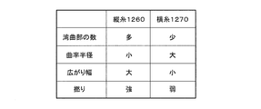
- the warp threads 1260 and the weft threads 1270 have different shapes from each other. Specifically, the warp 1260 and the weft 1270 have different curved shapes and twisted states. More specifically, as shown in FIG. 13, the warp 1260 has a curved portion per unit length (see curved portion R1 and curved portion R3 in FIG. 12B) as compared with the weft 1270. a lot. Further, the warp yarn 1260 has a smaller radius of curvature of the curved portion than the weft yarn 1270. In other words, the warp 1260 is formed to be more curved than the weft 1270.
- the warp yarn 1260 has a larger width (spread width, see width S1 and width S3 in FIG. 12B) in the direction intersecting each longitudinal direction as compared with the weft yarn 1270. .. Further, the warp yarn 1260 has a stronger twist than the weft yarn 1270. In other words, the warp 1260 is twisted to have a higher fiber density than the weft 1270. Therefore, the warp yarns 1260 have a larger number of fibers per unit area than the weft yarns 1270.
- the culture solution in which the carrier 120 flows down from the upper side to the lower side in the vertical direction is promoted to spread in the width direction. Then, as the culture solution spreads in the width direction, the time for the culture solution to flow down the carrier 120 becomes longer, and the amount of carbon dioxide gas supplied to the culture solution can be increased. In addition, the amount of light received by the microorganisms contained in the culture solution can be increased. As a result, the microorganisms are more easily cultured in the culture system 1 (see FIG. 1).
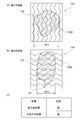
- FIGS. 14A and 14B are views for explaining the dropping test of the carrier 120.
- FIG. 14 (a) is a diagram showing the results of the vertical test
- FIG. 14 (b) is a diagram showing the results of the horizontal test
- FIG. 14 (c) shows the arrangement of the carrier 120. It is a figure which shows the relationship of diffusion.
- FIGS. 14A and 14B the description of the weft 1270 is omitted.
- FIG. 14A the arrangement of the warp threads 1260 along the vertical direction (longitudinal arrangement) is the direction in which the carrier 120 is installed in the culture system 1 (see FIG. 1).
- FIG. 14B the arrangement in which the warp threads 1260 intersect in the vertical direction (horizontal arrangement) is a direction different from the direction in which the carrier 120 is installed in the culture system 1.
- the test conditions for the drop test are as follows. First, the carrier 120 immersed in water in the container (not shown) was lifted in the air, suspended from a support mechanism (not shown), and the carrier 120 was installed in the vertical direction. Then, after 15 seconds had elapsed, 100 ⁇ L of ink solution was attached to the carrier 120 using a micropipette. Then, after 30 seconds had passed from the adhesion, the spread of the ink liquid on the carrier 120 was confirmed. As the carrier 120, a nylon towel (manufactured by Lifelex) was used. Further, unlike FIG. 12A, the carrier 120 used was composed of a single layer.
- the ink diffusion region 136 in the vertical test shown in FIG. 14 (a) has a longer horizontal length than the ink diffusion region 137 in the horizontal test shown in FIG. 14 (b). It was confirmed that it would be longer. Specifically, the maximum horizontal width W11 of the diffusion region 136 was 6.3 cm, and the maximum horizontal width W12 of the diffusion region 137 was 4.8 cm when 30 seconds had passed since the adhesion. From this, in the vertical arrangement (see FIG. 14 (a)), the carrier 120 has the warp threads 1260 in the vertical direction as shown in FIG. 14 (a) rather than the horizontal arrangement (see FIG. 14 (b)). When the carrier 120 is arranged in a direction in which the warp threads 1260 intersect in the vertical direction as shown in FIG. 14 (b), the diffusion of water in the horizontal direction is further promoted. More specifically, as shown in FIG. 14 (c), the vertical arrangement (see FIG. 14 (a)) diffuses water faster than the horizontal arrangement (see FIG. 14 (b)).
- the aspect ratio of the diffusion region 136 was 1.2 at the maximum position
- the aspect ratio of the diffusion region 137 was 0.7 at the maximum position
- the area was about 167,171 cm 2 .
- the average thickness of water can be obtained by dividing 100 ⁇ L by the area, and if it is 100 cm 2 , the water thickness is 10 ⁇ m.
- the diffusion regions 136 and 137 were further expanded. It is also considered that this is because the water thickness could not be maintained and spread. The water thickness at this time is calculated to be 6 ⁇ m on average.
- the vertical arrangement in the network structure of the carrier 120, in the water flow of the culture solution, the vertical arrangement (see FIG. 14A) is more horizontal than the horizontal arrangement (see FIG. 14B). Spreads quickly. Therefore, as the orientation in which the carrier 120 is mounted in the culture system 1 (see FIG. 1), the microorganisms are more likely to stay in the carrier 120 in the vertical arrangement shown in FIG. 14 (a). As a result, the microorganisms are more easily cultured in the culture system 1 (see FIG. 1).
- FIGS. 15A and 15B are views for explaining the tensile test of the carrier 120. Specifically, FIG. 15 (a) is a diagram showing a vertical test piece, FIG. 15 (b) is a diagram showing a horizontal test piece, and FIG. 15 (c) is a diagram showing the result of a tensile test. Is. In addition, in FIGS. 15A and 15B, the description of the weft 1270 is omitted.
- the longitudinal test piece is a test piece whose longitudinal direction is a direction along the warp 1260 (hereinafter, may be referred to as a longitudinal direction).
- the lateral test piece is a test piece whose longitudinal direction is a direction intersecting with the warp 1260 (hereinafter, may be referred to as a lateral direction).
- the length (see L10 in the figure) of the vertical test piece and the horizontal test piece was 10 cm, and the width (see W10 in the figure) was 3 cm.
- As the carrier 120 a nylon towel (manufactured by Lifelex) was used. Further, unlike FIG. 12A, the carrier 120 used was composed of a single layer.
- a desktop precision universal testing machine AGS-J manufactured by Shimadzu Corporation equipped with a 5 kN load cell and a 1 kN tensile test jig was used.
- the measurement conditions were a distance between jigs of 100 mm and a speed of 50 mm / min at room temperature.
- the vertical test piece had a larger elongation rate and fracture strength than the horizontal test piece.
- the difference in the elongation rates of the longitudinal test piece and the transverse test piece is due to the shapes of the warp 1260 and the weft 1270 being different from each other as described above. More specifically, when the warp threads 1260 are stretched in the direction along the warp threads 1260 as in the warp direction test piece, the warp threads 1260 are mainly stretched. On the other hand, in the case of stretching in the direction intersecting the warp 1260, that is, in the direction along the weft 1270 like the weft test piece, the weft 1270 is mainly stretched.
- the warp 1260 has more curved portions than the weft 1270. From this, it can be considered that the longitudinal test piece in which the warp 1260 is stretched has a larger elongation rate than the lateral test piece in which the weft 1270 is stretched.
- the carrier 120 is provided by suspending the warp threads 1260 in the vertical direction. That is, the warp threads 1260, which are more stretchable, are arranged along the vertical direction.
- the warp threads 1260 are configured to be more stretchable, the upper portion of the carrier 120 suspended and provided in the vertical direction is in a more stretched state as compared with the lower portion. Therefore, the upper portion of the carrier 120 suspended and provided in the vertical direction has a larger opening 1280 (see FIG. 12B) as compared with the lower portion.
- the carbon dioxide gas supplied to the culture solution can be increased.
- the carrier 120 carbon dioxide gas is supplied to the culture solution flowing from the upper side in the vertical direction to the lower side. Therefore, the culture solution passing through the upper side of the carrier 120 contains less carbon dioxide gas than the culture solution passing through the lower side. Therefore, the efficiency of supplying carbon dioxide gas in the carrier 120 can be improved by increasing the opening 1280 in the upper portion of the carrier 120, which is a region in which the culture solution contains a small amount of carbon dioxide gas.
- FIG. 16 is a flowchart illustrating a sterilization process in the culture system 1. Next, the sterilization treatment in the culture system 1 will be described. Although the description is omitted above, foreign matter may be mixed into the culture system 1 as the culture system 1 is operated. If this foreign substance is a fungus such as a mold, it may grow in the culture system 1 and reduce the yield of microorganisms.
- the culture system 1 may have a sterilizing unit (not shown) for sterilizing the mixed fungi.
- This sterilizing unit has a sterilizing water supply function of supplying so-called sterilizing water such as hydrogen peroxide solution into the culture system 1 and a drying function of supplying a gas having a predetermined temperature into the culture system 1 to dry the sterilizing water.
- a process of sterilizing the culture system 1 is performed at a predetermined timing (for example, every 7 days). This suppresses the reduction in the yield of microorganisms.
- the sterilization here means not only killing all the fungi mixed in the culture system 1, but also reducing the number of fungi mixed in the culture system 1 or suppressing the growth of the fungi. Including.
- control unit 90 determines whether the sterilization timing is predetermined (S1601). When the sterilization timing is reached, the pump 59 is stopped (S1602). Along with this, the circulation of the culture solution in the culture system 1 is stopped.
- the pump 59 circulates the culture solution again at a flow rate larger than the flow rate of the culture solution before stopping (S1603).
- the culture solution flowing at an increased flow rate peels off the microorganisms attached to the carrier 120 from the carrier 120.
- the pump 59 is stopped again at a predetermined timing (S1604).
- the microorganisms stripped from the carrier 120 by the culture solution are harvested by being filtered by the filter 37 (S1605).
- the sterilizing unit supplies sterilizing water into the culture system 1 (S1606). Along with this, the fungi mixed in the culture system 1 are sterilized. Then, the sterilizing unit supplies a gas having a predetermined temperature to the culture system 1 to dry the sterilizing water (S1607).
- the sterilization timing for executing the above sterilization treatment may be determined according to the growth rate of the fungi or the timing at which the microorganisms are harvested.
- mold spores are generally known to grow in about 7 days. Therefore, if the sterilization treatment is performed 7 days after the previous sterilization timing, the mold can be reliably sterilized even if the mold spores remain in the previous sterilization.
- the configuration of the carrier 120 is not particularly limited as long as it has warp 1260 and weft 1270.
- the carrier 120 can be regarded as, for example, a woven fabric or a mesh body.
- the carrier irradiation unit 70 and the culture irradiation unit 80 are provided, but the carrier irradiation unit 70 and the culture irradiation unit 80 are not provided in the culture system 1, and the carrier 120 and the like receive sunlight. This may allow the microorganism to be cultivated.
- a culture curve of green algae mounted on a carrier was created.
- a carrier made of cotton cloth is equipped with the green alga Chlorella quesleri 11h (formerly called IAM C-531 and now renamed to Parachlorella quesleri NIES-2160) so that the dry weight is 1 g per 1 m 2. did.
- Such a carrier was placed in 0.2x Gambog B5 medium (manufactured by Nihon Pharmaceutical Co., Ltd.) so as to spread vertically.
- FIG. 17 When the vertical axis is the logarithmic axis as shown in FIG. 17 (a), the same culture curve as the suspension culture in the liquid medium can be obtained in the culture of green algae mounted on the carrier, but FIG. 17 When the vertical axis was the linear axis as shown in (b), it was found that the cell mass increased by an equal amount. This result suggests that when culturing on a carrier, the surface green algae can always obtain sufficient light and retain the growth ability of logarithmic growth.
- the photosynthetic microorganism can be continuously produced as long as a sufficient amount of light can be supplied to the surface of the carrier, and it is clarified that the microorganism culture system of the present invention can be suitably used for the production of the photosynthetic microorganism. It was.
Landscapes
- Engineering & Computer Science (AREA)
- Life Sciences & Earth Sciences (AREA)
- Health & Medical Sciences (AREA)
- Chemical & Material Sciences (AREA)
- Bioinformatics & Cheminformatics (AREA)
- Biotechnology (AREA)
- Organic Chemistry (AREA)
- Zoology (AREA)
- Wood Science & Technology (AREA)
- Genetics & Genomics (AREA)
- General Engineering & Computer Science (AREA)
- Biomedical Technology (AREA)
- Microbiology (AREA)
- Medicinal Chemistry (AREA)
- Biochemistry (AREA)
- General Health & Medical Sciences (AREA)
- Virology (AREA)
- Tropical Medicine & Parasitology (AREA)
- Cell Biology (AREA)
- Botany (AREA)
- Sustainable Development (AREA)
- Apparatus Associated With Microorganisms And Enzymes (AREA)
- Micro-Organisms Or Cultivation Processes Thereof (AREA)
Abstract
本発明は、例えばプールやタンクのみを用いて培養対象を培養する場合と比較して、培養の効率を向上させることが可能な培養装置などを提供することを課題とする。 本発明の培養装置は、培養液が表面および/または内部を流下する担体と、担体に培養液を供給する供給部とを備える、担体は、上下方向に沿う向きに配置される複数の第1繊維と、上下方向と交差する向きに配置される複数の第2繊維とを有し、第2繊維に沿う向きの培養液の拡散速度は、担体が第2繊維が上下方向に沿う向きに配置される場合における、第1繊維に沿う向きの培養液の拡散速度よりも速い培養装置である。
Description
本発明は、培養装置、担体支持装置、および培養対象の製造方法に関する。
地球温暖化対策として、温暖化ガスの排出を可及的に抑える取り組み等が各国の産業界に強く求められている。クロレラ等の微細藻類や光合成細菌などの微生物は、CO2を排出しないでエネルギー生産が可能な資源その他の産業上利用可能な資源として非常に有望視されており、商業レベルでの活用および効率的な製造に期待が寄せられている。
微細藻類をエネルギー資源その他の産業上の利用に供するためには、できるだけ低いコストで生産することが要求される。そして、微細藻類の培養システムとして、大規模なプールやタンクを用いて、微細藻類を水中で大量に培養するシステムが知られている。
例えば、特許文献1においては、光合成微細藻類と培養液の混合液を収容する培養槽(又は培養池)において、光合成微細藻類として、光を吸収し二酸化炭素を取り込み光合成を行うことで油を生成する光合成微細藻類を用い、油を生成した光合成微細藻類を、回収手段によって、浮上している状態で回収するようにし、その結果、培養した光合成微細藻類に同伴される培養液を大幅に低減する光合成微細藻類培養装置が開示されている。
ところで、例えばプールやタンクを用いて培養対象を培養する場合において、培養の効率を向上させることが要求されている。
そこで、本発明は、培養の効率を向上させることが可能な培養装置などを提供することを目的とする。
そこで、本発明は、培養の効率を向上させることが可能な培養装置などを提供することを目的とする。
かかる目的のもと、本明細書に開示される技術は、培養液が表面および/または内部を流下する担体と、当該担体に培養液を供給する供給部とを備える培養装置であって、前記担体は、上下方向に沿う向きに配置される複数の第1繊維と、上下方向と交差する向きに配置される複数の第2繊維とを有し、前記第2繊維に沿う向きの培養液の拡散速度は、前記担体が当該第2繊維が上下方向に沿う向きに配置される場合における、前記第1繊維に沿う向きの培養液の拡散速度よりも速い培養装置である。
ここで、前記第1繊維および前記第2繊維は各々湾曲部を有し、当該第1繊維の湾曲部は、当該第2繊維の湾曲部よりも数が多いとよい。
また、前記第1繊維および前記第2繊維は各々湾曲部を有し、当該第1繊維の湾曲部は、当該第2繊維の湾曲部よりも曲率半径が小さいとよい。
また、前記担体は、前記複数の第1繊維および前記複数の第2繊維により形成される繊維層を積層して構成されるとよい。
また、前記第1繊維および前記第2繊維は、前記担体に照射される光の少なくとも一部を透過可能であるとよい。
また、前記担体は、前記培養装置において吊り下げて設けられ、前記第1繊維に沿う向きの方が前記第2繊維に沿う向きよりも伸びやすいとよい。
また、前記第1繊維および前記第2繊維は各々湾曲部を有し、当該第1繊維の湾曲部は、当該第2繊維の湾曲部よりも曲率半径が小さいとよい。
また、前記担体は、前記複数の第1繊維および前記複数の第2繊維により形成される繊維層を積層して構成されるとよい。
また、前記第1繊維および前記第2繊維は、前記担体に照射される光の少なくとも一部を透過可能であるとよい。
また、前記担体は、前記培養装置において吊り下げて設けられ、前記第1繊維に沿う向きの方が前記第2繊維に沿う向きよりも伸びやすいとよい。
他の観点から捉えると、本明細書に開示される技術は、培養液が表面および/または内部を流下する担体と、当該担体に培養液を供給する供給部とを備える培養装置であって、前記担体は、上下方向に沿う向きに配置される複数の第1繊維と、上下方向と交差する向きに配置される複数の第2繊維とを有し、前記担体は、前記培養装置において吊り下げて設けられ、前記第1繊維に沿う向きの方が前記第2繊維に沿う向きよりも伸びやすい培養装置である。
他の観点から捉えると、本明細書に開示される技術は、担体の表面および/または内部を培養液が流下するステップと、前記担体に培養液を供給するステップとを有し、前記担体は、上下方向に沿う向きに配置される複数の第1繊維と、上下方向と交差する向きに配置される複数の第2繊維とを有し、前記第2繊維に沿う向きの培養液の拡散速度は、前記担体が当該第2繊維が上下方向に沿う向きに配置される場合における、前記第1繊維に沿う向きの培養液の拡散速度よりも速い培養対象の製造方法である。
本明細書に開示される技術によれば、培養の効率を向上させることが可能な培養装置などを提供することができる。
以下、本発明の微生物培養システムの一実施形態について図面を参照して説明する。
<培養システム1>
図1は、本実施の形態に係る培養システム1を示す概略構成図である。
まず、図1を参照して、本実施の形態が適用される培養システム1の概略構成を説明する。
<培養システム1>
図1は、本実施の形態に係る培養システム1を示す概略構成図である。
まず、図1を参照して、本実施の形態が適用される培養システム1の概略構成を説明する。
図1に示すように、培養装置の一例である培養システム1は、微生物を含む培養液が供給される担体ユニット10と、微生物を培養する培養ユニット30と、微生物を含む培養液を循環させる培養液循環ユニット50と、担体ユニット10にガスを供給するガス供給ユニット60と、担体ユニット10に光を照射する担体照射ユニット70と、培養ユニット30に光を照射する培養照射ユニット80と、各構成部材を制御する制御ユニット90とを有する。
なお、以下の説明においては、図1に示す培養システム1の上下方向を、単に上下方向ということがある。また、培養システム1の幅方向を、単に幅方向ということがある。また、培養システム1における上下方向および幅方向と交差する方向を、単に奥行方向ということがある。
図1に示すように、担体ユニット10は、微生物を含む培養液が供給される担体12と、担体12の外周を覆うカバー15と、担体12およびカバー15を支持する支持体17とを有する。図示の例においては、カバー15に収容された担体12が、奥行方向に複数(2つ)並べて設けられている。収容体の一例であるカバー15内においては、微生物を含む培養液が担体12に沿って流れ落ちるとともに、光が照射されかつ炭酸ガスが供給される。担体ユニット10の詳細については後述する。
培養部の一例である培養ユニット30は、培養液が貯留されるとともに微生物が培養される培養槽31と、培養槽31内の培養液を攪拌する攪拌器35と、培養した微生物をろ過するろ過器37とを有する。
培養槽31は、上下方向上側が開放されている容器である。この培養槽31においては、貯留する培養液が外気と接触可能である。すなわち、培養槽31は、外気を内部に取り込む開口を有する構成である。また、培養槽31は、培養照射ユニット80が照射する光に対して透明な樹脂やガラスなどで形成される。すなわち、培養槽31の側面は、培養液に向かう光を通過させる通過領域として機能する。
攪拌部の一例である攪拌器35は、培養槽31内に設けられた不図示の回転子を回転させることにより、培養槽31内の培養液を攪拌する。ここで、攪拌器35は、培養槽31内の培養液をかき混ぜることが可能であれば、回転子を用いる構成に限定されない。例えば、培養槽31内に炭酸ガスなどの気体や、培養液などの液体を供給することで培養液を攪拌してもよい。また、例えば超音波などにより、培養槽31を振動させることで培養液を攪拌してもよい。
ろ過器37は、培養槽31から、培養された微生物を培養液とともに受ける。そして、ろ過器37は、培養液からろ過により微生物を分離することで微生物を回収する。なお、ろ過器37によって微生物が分離された培養液、すなわちろ液は、廃棄されてもよいし、培養槽31へ供給し、再び微生物の培養に利用してもよい。
供給部の一例である培養液循環ユニット50は、担体ユニット10に培養液を供給する第1配管51と、担体ユニット10から培養液を回収する第2配管53と、培養槽31から培養液を循環させる第3配管57と、培養液を循環させる駆動源であるポンプ59とを有する。培養液循環ユニット50は、ポンプ59によって培養槽31から担体ユニット10に微生物および培養液を供給し、担体ユニット10から培養液とともに微生物を培養槽31へと回収することを繰り返すことで、微生物および培養液を循環させる。なお、図示の培養ユニット30は、担体ユニット10の上下方向下側からずれた位置に配置されている。すなわち、培養ユニット30は、担体ユニット10とは異なる地点に設けられている。図示の例においては、第1配管51、第2配管53、および第3配管57によって、異なる地点に設けられ互いに離間した担体ユニット10および培養ユニット30が互いに接続される。
ガス供給部の一例であるガス供給ユニット60は、炭酸ガスを圧縮して収容するガスボンベ61と、ガスボンベ61から供給される炭酸ガスを担体ユニット10に供給するガス配管63とを有する。
照射部の一例である担体照射ユニット70は、担体ユニット10を挟んで奥行方向両側から担体ユニット10に向けて光を照射する第1照射パネル71および第2照射パネル73を有する。図示の例においては、第1照射パネル71および第2照射パネル73は、担体ユニット10に対向配置する略板状の形状である。第1照射パネル71および第2照射パネル73は、例えば、光源として蛍光灯、有機ELまたはLED等を配列しており、微生物の増殖に適した波長や光量の光を照射するように構成されている。第1照射パネル71および第2照射パネル73が照射する光の波長は、例えば380~780nmの範囲である。また、第1照射パネル71および第2照射パネル73は、例えば赤色光のみで増殖が可能な微生物に対しては、赤色光のみを照射できるとよい。
照射部の一例である担体照射ユニット70は、担体ユニット10を挟んで奥行方向両側から担体ユニット10に向けて光を照射する第1照射パネル71および第2照射パネル73を有する。図示の例においては、第1照射パネル71および第2照射パネル73は、担体ユニット10に対向配置する略板状の形状である。第1照射パネル71および第2照射パネル73は、例えば、光源として蛍光灯、有機ELまたはLED等を配列しており、微生物の増殖に適した波長や光量の光を照射するように構成されている。第1照射パネル71および第2照射パネル73が照射する光の波長は、例えば380~780nmの範囲である。また、第1照射パネル71および第2照射パネル73は、例えば赤色光のみで増殖が可能な微生物に対しては、赤色光のみを照射できるとよい。
他の照射部の一例である培養照射ユニット80は、培養槽31を挟んで奥行方向両側から担体ユニット10に向けて光を照射する第1照射パネル81および第2照射パネル83を有する。この第1照射パネル81および第2照射パネル83は、第1照射パネル71および第2照射パネル73と同様に構成されている。さらに説明をすると、第1照射パネル81および第2照射パネル83は、例えば、光源として蛍光灯、有機ELまたはLED等を配列しており、微生物の増殖に適した波長や光量の光を照射するように構成されている。第1照射パネル81および第2照射パネル83が照射する光の波長は、例えば380~780nmの範囲である。また、第1照射パネル81および第2照射パネル83は、例えば赤色光のみで増殖が可能な微生物に対しては、赤色光のみを照射できるとよい。図示の例においては、第1照射パネル81および第2照射パネル83は、担体ユニット10に対向配置する略板状の形状であるが、培養槽31に光を照射可能であれば、例えば上下方向上側からのみ照射するなど、構造は特に限定されない。
制御ユニット90は、コンピュータなどにより構成され、培養システム1の構成部材を制御する。例えば、制御ユニット90は、培養液循環ユニット50の動作タイミングを制御する。
培養システム1においては、培養ユニット30で微生物が培養される。そして、培養液循環ユニット50によって微生物を含む培養液を循環させながら、担体ユニット10で微生物および培養液への炭酸ガスの供給および光の照射が実行される。すなわち、担体ユニット10において、微生物が光合成を行なうのに必要な炭酸ガスおよび光エネルギーが供給される。そして、微生物および培養液が再び培養ユニット30へと導かれ、培養ユニット30において微生物が培養される。また、培養ユニット30においては、培養照射ユニット80によって光が照射されることにより、微生物の培養が促進される。
なお、培養システム1においては、培養液が培養ユニット30を通過するのに要する時間は、培養液が担体ユニット10を通過するのに要する時間よりも長い。言い替えると、培養液が培養槽31に貯留される時間は、培養液が担体12を流れ落ちる時間よりも長い。また、ある時点において、培養槽31に貯留される培養液の量は、カバー15内に存在する培養液の量よりも多い。
ここで、培養対象とする微生物は例えば光合成細菌や光合成微細藻類等の光合成微生物である。なお、光合成を行わずに増殖できる微生物を培養する場合においては、培養システム1が担体照射ユニット70および培養照射ユニット80を備えなくてもよい。
また、培養液としては、微細藻類を通常の方法により培養して、微生物の濃度を高めることが可能な培地の希釈液であれば、特に制限されない。培地としては、例えばCHU培地、JM培地、MDM培地などの一般的な無機培地を用いることができる。さらに、培地としては、ガンボーグB5培地、BG11培地、HSM培地の各種培地の希釈液が好ましい。無機培地には、窒素源としてCa(NO3)2・4H2OやKNO3、NH4Clが、その他の主要な栄養成分としてKH3PO4やMgSO4・7H2O、FeSO4・7H2Oなどが含まれる。また、培地には、微細藻類の生育に影響を与えない抗生物質等を添加してもよい。培地のpHは4~10が好ましい。また、各種産業から排出される廃水等を利用してもよい。
また、培養液としては、微細藻類を通常の方法により培養して、微生物の濃度を高めることが可能な培地の希釈液であれば、特に制限されない。培地としては、例えばCHU培地、JM培地、MDM培地などの一般的な無機培地を用いることができる。さらに、培地としては、ガンボーグB5培地、BG11培地、HSM培地の各種培地の希釈液が好ましい。無機培地には、窒素源としてCa(NO3)2・4H2OやKNO3、NH4Clが、その他の主要な栄養成分としてKH3PO4やMgSO4・7H2O、FeSO4・7H2Oなどが含まれる。また、培地には、微細藻類の生育に影響を与えない抗生物質等を添加してもよい。培地のpHは4~10が好ましい。また、各種産業から排出される廃水等を利用してもよい。
<担体ユニット10>
図2は、担体12の斜視図である。
図3は、担体ユニット10の概略構成図である。
次に、図1乃至図3を参照しながら、担体ユニット10の詳細構成を説明する。
上記のように、担体ユニット10は、担体12と、カバー15と、支持体17とを有する。以下、各々の構成について説明をする。
図2は、担体12の斜視図である。
図3は、担体ユニット10の概略構成図である。
次に、図1乃至図3を参照しながら、担体ユニット10の詳細構成を説明する。
上記のように、担体ユニット10は、担体12と、カバー15と、支持体17とを有する。以下、各々の構成について説明をする。
まず、担体12について説明をする。
図2に示すように、担体12は、微生物を含む培養液が通過する板状部材である。図示の担体12は、正面視略長方形の布部材である。より具体的には、担体12は、可撓性を有する部材、より具体的にはポリエステルなどの樹脂繊維により構成されている。また、図示の担体12は、第1照射パネル71および第2照射パネル73から照射される光の少なくとも一部を透過する糸状部材により形成される。なお、担体12の材質は特に限定されるものではなく、綿、絹、毛、アクリル等を用いてもよい。
図2に示すように、担体12は、微生物を含む培養液が通過する板状部材である。図示の担体12は、正面視略長方形の布部材である。より具体的には、担体12は、可撓性を有する部材、より具体的にはポリエステルなどの樹脂繊維により構成されている。また、図示の担体12は、第1照射パネル71および第2照射パネル73から照射される光の少なくとも一部を透過する糸状部材により形成される。なお、担体12の材質は特に限定されるものではなく、綿、絹、毛、アクリル等を用いてもよい。
ここで、担体12は、担体12の長手方向に沿って配置される縦糸126と、担体12の長手方向と交差する方向(幅方向)に沿って配置される複数の横糸127とを有する。縦糸126は、幅方向において予め定めた間隔で複数設けられている。また、横糸127は、長手方向において予め定めた間隔で複数設けられている。したがって、担体12は、網目状に形成された網体として捉えることができる。この担体12においては、複数の開口128が形成される。詳細は後述するが、開口128は、微生物が通過可能な寸法である。また、開口128は、担体12の厚み方向において貫通する貫通孔として捉えることができる。また、縦糸126および横糸127の少なくとも一方は、複数の湾曲部を有する所謂ウェーブ状の繊維部材であってもよい。
ここで、担体12は、担体ユニット10においては長手方向の略中央で2つに折り曲げられて設けられている(図1参照)。担体12の寸法は、特に限定されないが、より効率的に微生物を培養するために大きく形成される。例えば、担体12は、展開した際の長手方向の長さが2.5mで、幅方向の長さが1mの布部材を用いて、縦寸法が約1.25mになるように長手方向の略中央で折り曲げられる。担体の1m2当たりの微生物の搭載量を高めるために、担体12の表面に凹凸や細孔を設けてもよい。なお、本明細書における「担体1m2当たりの微生物の搭載量」とは、担体表面を平滑な平面と仮定したときの表面積1m2当たりの微生物の搭載量を意味し、凹凸や細孔を形成したことによる表面積増加を加味した実際の表面積を意味するものではない。
次に、カバー15について説明をする。
図1に示すように、カバー15は、可撓性を有するシート部材の長手方向の中央を折り曲げて形成されている。カバー15は、担体照射ユニット70から照射する光を透過する材質により構成される。カバー15は、例えば塩化ビニル、ポリエチレン、ポリエステル、ポリプロピレン、PET等の合成樹脂により構成される。
図1に示すように、カバー15は、可撓性を有するシート部材の長手方向の中央を折り曲げて形成されている。カバー15は、担体照射ユニット70から照射する光を透過する材質により構成される。カバー15は、例えば塩化ビニル、ポリエチレン、ポリエステル、ポリプロピレン、PET等の合成樹脂により構成される。
ここで、カバー15は、内部に担体12を収容できる偏平な袋状に形成されている。さらに説明をすると、カバー15は、一部を除き内部を密閉可能に形成されている。具体的には、図3に示すカバー15は、培養液を導出する導出口154、培養液を導入する導入口156、炭酸ガスを導入するガス口157を有する。
ここで、導出口154は、カバー15における上下方向下側の端部である下端部152に設けられる。この導出口154は、第2配管53が着脱できるようになっている。導入口156は、カバー15における上下方向上側に設けられる。この導入口156は、後述するカバー支持体171の端部が貫通する。また、ガス口157は、カバー15における上下方向中央部に設けられる。このガス口157は、後述するガス供給管177の端部が貫通する。
次に、支持体17について説明をする。
図3に示すように、支持部の一例である支持体17は、カバー15を支持するカバー支持体171と、担体12を支持する担体支持体173と、炭酸ガスを供給するガス供給管177と、カバー支持体171、担体支持体173、およびガス供給管177を支持する枠体179とを有する。なお、支持体17は、例えばアルミニウムなど微生物の培養を妨げない材質で形成される。
図3に示すように、支持部の一例である支持体17は、カバー15を支持するカバー支持体171と、担体12を支持する担体支持体173と、炭酸ガスを供給するガス供給管177と、カバー支持体171、担体支持体173、およびガス供給管177を支持する枠体179とを有する。なお、支持体17は、例えばアルミニウムなど微生物の培養を妨げない材質で形成される。
カバー支持体171は、幅方向に延びる円筒状の部材である。このカバー支持体171は、カバー15が掛けられる。また、カバー支持体171は、幅方向において予め定めた間隔で培養液排出孔175が形成されている。図示の例においては、カバー支持体171における上下方向下側の面に、培養液排出孔175が形成されている。この培養液排出孔175は、カバー支持体171内部から培養液を排出する。また、カバー支持体171は、一方の端部が導入口156から突出し、第1配管51に接続される。カバー支持体171の他方の端部は、不図示の配管に接続されている。この配管は、担体12に供給されなかった培養液を培養槽31へと案内する。
担体支持体173は、幅方向に延びる円柱状の部材である。この担体支持体173は、カバー支持体171よりも上下方向下側で、カバー支持体171に吊るされて設けられている。この担体支持体173は、折り曲げられた担体12が掛けられる部分である。なお、図示の例における担体支持体173は、カバー支持体171よりも奥行方向における寸法(外径)が小さい(後述する図4参照)。
ガス供給管177は、幅方向に延びる円筒状の部材である。このガス供給管177の外周にはガス排出孔178が複数形成されている。供給口の一例であるガス排出孔178は、上下方向両側および幅方向両側などに向けて開口している。ガス排出孔178は、ガス供給管177内部から炭酸ガスを排出する。また、ガス供給管177の端部は、ガス口157から突出し、ガス配管63に接続される。なお、図示の例におけるガス供給管177は、担体支持体173よりも奥行方向における寸法(外径)が小さい(後述する図4参照)。なお、培養システム1の担体12以外の部分は、担体支持装置として捉えることができる。
<担体ユニット10における配置>
図4は、図3のIV-IVにおける断面図である。
図5は図4の領域Vにおける拡大図である。
次に、図3乃至図5を参照しながら、担体ユニット10における担体12の周辺の構造について説明する。
図4は、図3のIV-IVにおける断面図である。
図5は図4の領域Vにおける拡大図である。
次に、図3乃至図5を参照しながら、担体ユニット10における担体12の周辺の構造について説明する。
図4に示すように、カバー15は、カバー支持体171に掛けられて配置される。このカバー15は、連続部の一例である曲げ部155を挟んで位置する第1部151と第2部153とを有する。第1部151と第2部153は、各々上下方向に沿って起立して設けられる。
また、担体12は、担体支持体173に掛けられて配置される。この担体12は、折り曲げられ湾曲した部分である曲げ部125を挟んで、平板部の一例である第1部121と第2部123とを有する形状である。第1部121および第2部123は、各々上下方向に沿って起立して設けられる。ここで、第1部121および第2部123は、互いに離間して配置される。また、第1部121および第2部123は、カバー15から離間して配置される。なお、第1部121および第2部123は、第1対向部および第2対向部の一例である。
ここで、担体12の曲げ部125の上下方向上側にカバー支持体171の培養液排出孔175が位置する。すなわち、他の供給口の一例である培養液排出孔175は、曲げ部125に向けて開口する。また、担体12の第1部121と第2部123との間には、ガス供給管177が配置される。このガス供給管177のガス排出孔178は、第1部121と第2部123によって挟まれる空間内に向けて開口する。
さて、図4に示すように、培養液排出孔175から排出される培養液は、担体12の曲げ部125に供給される(図中矢印A1参照)。この曲げ部125に供給された培養液は、第1部121および第2部123に分岐して流れ落ちる(図中矢印A3およびA5参照)。
また、ガス排出孔178から排出される炭酸ガスは、担体12の第1部121および第2部123によって挟まれる空間内に供給される(図中矢印B1乃至B4参照)。このとき、炭酸ガスは、一部が上下方向に流れ(図中矢印B1およびB2参照)、一部は奥行方向、すなわち第1部121と第2部123に向けて流れる(図中矢印B3およびB4参照)。
ここで、図5を参照しながら、担体12における培養液などの流れについて詳細に説明をする。
担体12の第1部121の表面および/または内部においては、培養液が上下方向上側から下側へと流れる(図中矢印A7参照)。
担体12の第1部121の表面および/または内部においては、培養液が上下方向上側から下側へと流れる(図中矢印A7参照)。
また、炭酸ガスは、奥行方向に沿って第1部121を通過する(図中矢印B5参照)。この炭酸ガスの流れは、培養液の流れ(図中矢印A7参照)と交差する向きである。また、炭酸ガスは、上下方向下側から上側へと流れる(図中矢印B6参照)。この炭酸ガスの流れは、培養液とは反対の向き、すなわち培養液と対向する向きである。このように、炭酸ガスが、培養液と交差する向き、および培養液と反対の向きに流れることにより、培養液に供給される炭酸ガスの量が増加し得る。
第2照射パネル73(図1参照)から照射された光は、奥行方向に沿って第1部121を通過する(図中矢印C1参照)。この光の進行方向は、培養液と交差する向きである。このことにより、培養液に含まれる微生物が受ける光量が増加し得る。
ここで、微生物は、培養液とともに、上下方向上側から下側に向けて流下する。すなわち、培養液流下開始の初期段階においては、微生物は、縦糸126に沿って落下する。ここで、縦糸126に沿って落下する微生物は、横糸127にぶつかると流れる向きが変わる(図中矢印A11、A13、A15、A17)。すなわち、微生物は、奥行方向において揺動しながら落下する。さらに説明をすると、微生物は、担体12の開口128を通過しながら落下する。このことにより、微生物がガスと接触する時間が長くなり、結果として微生物におけるガス交換効率が高まる。なお、図示の例においては、横糸127は、ウェーブ状に成型されており、各横糸127は奥行方向において互いにずれた配置となる。このことにより、微生物の奥行方向における揺動がより促進される。以上により、担体上での微生物の増殖が促進される。
<光合成微生物の製造>
本発明の微生物培養システムを用いた光合成微生物の製造について、以下詳述する。本発明の微生物培養システムの利点としては、オープンポンドでの培養と比較して増殖後の細胞の回収が容易であること、及び、光合成生物に適用した場合には、担体に付着あるいは滞留している細胞量が多くなっても増殖速度が保たれることにある。実施例2の結果を示す図17は、クロレラ細胞の布(本発明の担体12に対応)上での増殖曲線である。左図(a)は縦軸の微生物量を対数目盛で表し、右図(b)は線形目盛で表したものである。左図での直線部は指数的な増殖(対数増殖期)を表し、右図の直線部は直線増殖期を表す。したがって、本発明の微生物培養システムを用いた光合成微生物の製造における担体12上でも、はじめ対数増殖、その後、直線増殖となってほぼ飽和に近づきながら緩やかな増殖となり、基本的には、液体培地中での懸濁培養と類似の増殖曲線をとる。しかし、本発明の微生物培養システムを用いた光合成微生物の製造では、担体12上に付着あるいは滞留している細胞は、ほとんど移動しないため、その表面に位置する細胞が光を受光し続ける。そのため、光を受け続ける表層の細胞群と担体12との間にあって表層細胞群の陰に位置する内部細胞群との異なる環境の細胞群からなる。すなわち、表層の細胞群の細胞は、対数増殖の増殖能力を保持する細胞である。この点は、細胞濃度が高くなり直線増殖期に移行した液体培養中の細胞と異なる。オープンポンドでの培養では、攪拌により、細胞が照射光を直接受ける位置と他の細胞の陰になる位置とに移動が繰り返され、細胞数の増加に伴い全細胞の増殖能力が一様に抑制されるからである。よって、本発明の微生物培養システムを用いた光合成微生物の製造においては、倍加時間の遅い光合成微生物でも、担体12への付着量を高めることにより、より高い生産量が確保できる特徴をもつ。
本発明の微生物培養システムを用いた光合成微生物の製造について、以下詳述する。本発明の微生物培養システムの利点としては、オープンポンドでの培養と比較して増殖後の細胞の回収が容易であること、及び、光合成生物に適用した場合には、担体に付着あるいは滞留している細胞量が多くなっても増殖速度が保たれることにある。実施例2の結果を示す図17は、クロレラ細胞の布(本発明の担体12に対応)上での増殖曲線である。左図(a)は縦軸の微生物量を対数目盛で表し、右図(b)は線形目盛で表したものである。左図での直線部は指数的な増殖(対数増殖期)を表し、右図の直線部は直線増殖期を表す。したがって、本発明の微生物培養システムを用いた光合成微生物の製造における担体12上でも、はじめ対数増殖、その後、直線増殖となってほぼ飽和に近づきながら緩やかな増殖となり、基本的には、液体培地中での懸濁培養と類似の増殖曲線をとる。しかし、本発明の微生物培養システムを用いた光合成微生物の製造では、担体12上に付着あるいは滞留している細胞は、ほとんど移動しないため、その表面に位置する細胞が光を受光し続ける。そのため、光を受け続ける表層の細胞群と担体12との間にあって表層細胞群の陰に位置する内部細胞群との異なる環境の細胞群からなる。すなわち、表層の細胞群の細胞は、対数増殖の増殖能力を保持する細胞である。この点は、細胞濃度が高くなり直線増殖期に移行した液体培養中の細胞と異なる。オープンポンドでの培養では、攪拌により、細胞が照射光を直接受ける位置と他の細胞の陰になる位置とに移動が繰り返され、細胞数の増加に伴い全細胞の増殖能力が一様に抑制されるからである。よって、本発明の微生物培養システムを用いた光合成微生物の製造においては、倍加時間の遅い光合成微生物でも、担体12への付着量を高めることにより、より高い生産量が確保できる特徴をもつ。
以上に説明したとおり、本発明の微生物培養システムを光合成微生物に適用することにより、担体12に付着した細胞量を多くした場合であっても、表層の細胞群の細胞は、対数増殖の増殖能力を保持することができる。したがって、1日間に期待する生産量(乾燥重量gDW)をP(gDW/m2)、対数増殖時における細胞の1日間の増殖能力(単位期間あたりの倍率で表す)をμ倍としたときの1日の最初の細胞量C0(gDW/m2)は、P≦C0×(μ-1)だから、以下の式(1)
C0 ≧ P/(μ-1) ・・・(1)
により設定することができる(μは比増殖速度として、時に時間あたりで表される)。本発明においては、Pが例えば5g/m2以上、6g/m2以上、7g/m2以上、8g/m2以上、9g/m2以上、10g/m2以上、15g/m2以上、20g/m2以上になるように、最初の細胞量C0を設定することができる。Pの上限は特に限定されないが、担体12の表層の細胞に対する十分な光量を確保するため、300g/m2以下であることが好ましく、100g/m2以下がより好ましく、50g/m2以下がさらに好ましい。また、1日当たりの回収可能細胞量は、以下の式(2)
[回収可能細胞量(gDW/m2・日)]=[固相表面細胞量(gDW/m2)]×(2(24/倍加時間)-1) ・・・(2)
(式中、「固相表面細胞量」は、担体12上の光が十分当たる細胞量である)
により設定することができる。
C0 ≧ P/(μ-1) ・・・(1)
により設定することができる(μは比増殖速度として、時に時間あたりで表される)。本発明においては、Pが例えば5g/m2以上、6g/m2以上、7g/m2以上、8g/m2以上、9g/m2以上、10g/m2以上、15g/m2以上、20g/m2以上になるように、最初の細胞量C0を設定することができる。Pの上限は特に限定されないが、担体12の表層の細胞に対する十分な光量を確保するため、300g/m2以下であることが好ましく、100g/m2以下がより好ましく、50g/m2以下がさらに好ましい。また、1日当たりの回収可能細胞量は、以下の式(2)
[回収可能細胞量(gDW/m2・日)]=[固相表面細胞量(gDW/m2)]×(2(24/倍加時間)-1) ・・・(2)
(式中、「固相表面細胞量」は、担体12上の光が十分当たる細胞量である)
により設定することができる。
以下に実施例を掲げて本発明を更に詳細に説明するが、本発明はこれら実施例によって何ら限定されるものではない。
図6(a)乃至(d)は、実験1乃至4の条件を説明する図である。
図7は、実験1乃至4における収穫量を示すテーブルである。
図6(a)乃至(d)は、実験1乃至4の条件を説明する図である。
図7は、実験1乃至4における収穫量を示すテーブルである。
図1に示すような培養システム1を用いてスピルリナを培養した。担体12は、ナイロン製のメッシュ素材、所謂ナイロンタオル(ライフレックス社製)を用いた。担体12の寸法は幅18cm、長さ100cmとした。この担体12は、2つ折りで吊るしたものを2枚用いて測定を行った。また、カバー15は、厚さ0.45mmの塩化ビニールシートを2枚用い、各々担体12を収容させた。カバー支持体171は、アクリル製であり、寸法が厚さ3mm、呼び径16であるものを2本用いた。カバー支持体171の培養液排出孔175は、直径0.9mmであり、カバー支持体171の長手方向に沿って、2cmおきに9か所設けた。
第1照射パネル71、第2照射パネル73、第1照射パネル81および第2照射パネル83は、赤色LED(イフェクト社製)を用いて光を照射した。光の強さは担体12の端で50μmol/m2/sec、担体12の中央で20μmol/m2/secとした。
ポンプ59は、エーハイム水陸両用ポンプ1048を用いた。
第1配管51、第2配管53、第3配管57は、シリコン製ホース(10×13mm)を用いた。ここで、Y字コネクター(アズワン、1-7377-18)を用いることにより、第1配管51において2本のカバー支持体171へ分岐する流路を確保した。
培養槽31は、ポリプロピレン製であり、寸法は、幅30cm、奥行15cm、高さ30cmとした。培養液は、表1に示す通りである。

第1配管51、第2配管53、第3配管57は、シリコン製ホース(10×13mm)を用いた。ここで、Y字コネクター(アズワン、1-7377-18)を用いることにより、第1配管51において2本のカバー支持体171へ分岐する流路を確保した。
培養槽31は、ポリプロピレン製であり、寸法は、幅30cm、奥行15cm、高さ30cmとした。培養液は、表1に示す通りである。
図6(a)乃至(d)に示すように、担体ユニット10および培養ユニット30に対する光の照射条件を変化させながら、実験1乃至実験4を行った。具体的には、担体ユニット10および培養ユニット30の各々に対して、光を照射する場合と、光が照射されないよう遮光する場合とを切り替えた。さらに説明をすると、担体ユニット10の遮光は、担体ユニット10のカバー15をアルミ箔で覆うことにより行った。付言すると、担体ユニット10を遮光することで、担体ユニット10の担体12に光が到達しなくなる。また、培養ユニット30の遮光は、培養ユニット30の培養槽31をアルミ箔で覆うことにより行った。付言すると、培養ユニット30を遮光することで、培養ユニット30の培養槽31の内部に光が到達しなくなる。
図6(a)に示すように、実験1においては、担体ユニット10および培養ユニット30の両者を遮光した。図6(b)に示すように、実験2においては、担体ユニット10には光を照射し、培養ユニット30を遮光した。図6(c)に示すように、実験3においては、担体ユニット10を遮光し、培養ユニット30には光を照射した。図6(d)に示すように、実験4においては、担体ユニット10および培養ユニット30の両者に光を照射した。
実験1乃至実験4の各々における培養養開始時には、各担体12にスピルリナを1g均等に乗せ(2枚合計で2g)た後、カバー15内に収容した。培養槽31には培養液を5L入れポンプ59で循環させた。培養中は、培養槽31内の培養液の温度が30℃となるように室温を調整した。この条件で12日間培養を行った結果、担体12(2枚)および培養槽31内のスピルリナを回収、すなわち収穫して重量を測定した。
図7に示すように、実験1においては、スピルリナの収穫量が2.33gであった。同様に、実験2では収穫量が10.15gであり、実験3では収穫量が4.16gであり、実験4では収穫量が11.73gであった。このことから、担体ユニット10および培養ユニット30の両者に光を照射した実験4では、担体ユニット10のみに光を照射した実験2や、培養ユニット30のみに光を照射した実験3と比較して、収穫量が増加することが確認された。
<培養対象>
上記のように培養システム1が培養する培養対象は、クロレラやシネコキスティス、スピルリナのような運動性のないあるいは乏しい光合成微生物だけでなく、鞭毛で水中を運動するプランクトン性のユーグレナやクラミドモナス、プレウロクリシスも含まれる。言い替えると、培養システム1の培養対象となる微生物は、きわめて多様である。培養システム1の培養対象となる主な微生物群としては、例えば以下のA類、B類、C類が挙げられる。
上記のように培養システム1が培養する培養対象は、クロレラやシネコキスティス、スピルリナのような運動性のないあるいは乏しい光合成微生物だけでなく、鞭毛で水中を運動するプランクトン性のユーグレナやクラミドモナス、プレウロクリシスも含まれる。言い替えると、培養システム1の培養対象となる微生物は、きわめて多様である。培養システム1の培養対象となる主な微生物群としては、例えば以下のA類、B類、C類が挙げられる。
まず、A類として、原核生物である真正細菌と古細菌を挙げることができる。
真正細菌には、酸素非発生型の光合成細菌や酸素発生型光合成を行うシアノバクテリア、有機物質を利用する通性嫌気性発酵性細菌と非発酵性細菌、さらに無機栄養細菌、放線菌およびコリネバクテリウム、有胞子細菌を挙げることができる。光合成細菌には、ロドバクター、ロドスピリルム、クロロビウム、クロロフレクサスが挙げられる。シアノバクテリアにはシネココッカス、シネコキスティス、スピルリナ、アルスロスピラ、ノストック、アナベナ、オシラトリア、リングビア、イシクラゲ、スイゼンジノリが挙げられる。通性嫌気性発酵性細菌として大腸菌、乳酸菌が挙げられる。非発酵性細菌としてシュードモナスが挙げられる。無機栄養細菌として水素細菌が挙げられる。放線菌としてストレプトマイセスが、有胞子細菌として枯草菌が挙げられる。古細菌は好熱菌や高度好塩菌が挙げられる。好熱菌としてサーモコッカスが、高度好塩菌としてハロバクテリウムが挙げられる。その他に、グルタミン酸生産菌、リジン生産菌、セルロース生産菌などが挙げられる。
真正細菌には、酸素非発生型の光合成細菌や酸素発生型光合成を行うシアノバクテリア、有機物質を利用する通性嫌気性発酵性細菌と非発酵性細菌、さらに無機栄養細菌、放線菌およびコリネバクテリウム、有胞子細菌を挙げることができる。光合成細菌には、ロドバクター、ロドスピリルム、クロロビウム、クロロフレクサスが挙げられる。シアノバクテリアにはシネココッカス、シネコキスティス、スピルリナ、アルスロスピラ、ノストック、アナベナ、オシラトリア、リングビア、イシクラゲ、スイゼンジノリが挙げられる。通性嫌気性発酵性細菌として大腸菌、乳酸菌が挙げられる。非発酵性細菌としてシュードモナスが挙げられる。無機栄養細菌として水素細菌が挙げられる。放線菌としてストレプトマイセスが、有胞子細菌として枯草菌が挙げられる。古細菌は好熱菌や高度好塩菌が挙げられる。好熱菌としてサーモコッカスが、高度好塩菌としてハロバクテリウムが挙げられる。その他に、グルタミン酸生産菌、リジン生産菌、セルロース生産菌などが挙げられる。
次に、B類として、真核光合成微生物である微細藻類を挙げることができる。
微細藻類には、緑藻、トレボキシア藻、紅藻、珪藻、ハプト藻、真正眼点藻、ユーグレナ、褐虫藻が挙げられる。
緑藻にはクロレラ、セネデスムス、クラミドモナス、ボトリオコッカス、ヘマトコッカス、ナンノクロリス、シュードコリシスティスが、トレボキシア藻としてパラクロレラやココミクサが挙げられる。紅藻としてシアニディオシゾン、シアニディウム、ガルディエリア、ポルフィリディウムが、珪藻としてニッチア、フェオダクティルム、キートケロス、タラシオシラ、スケレトネマ、フィツリフェラが挙げられる。ハプト藻として、プレウロクリシス、ゲフィロカプサ、エミリアニア、イソクリシス、パブロバが挙げられる。真正眼点藻としてナンノクロロプシス、ユーグレナとしてユーグレナが挙げられる。さらに、サンゴの共生藻である褐虫藻としてはシンビオディニウムが挙げられる。
微細藻類には、緑藻、トレボキシア藻、紅藻、珪藻、ハプト藻、真正眼点藻、ユーグレナ、褐虫藻が挙げられる。
緑藻にはクロレラ、セネデスムス、クラミドモナス、ボトリオコッカス、ヘマトコッカス、ナンノクロリス、シュードコリシスティスが、トレボキシア藻としてパラクロレラやココミクサが挙げられる。紅藻としてシアニディオシゾン、シアニディウム、ガルディエリア、ポルフィリディウムが、珪藻としてニッチア、フェオダクティルム、キートケロス、タラシオシラ、スケレトネマ、フィツリフェラが挙げられる。ハプト藻として、プレウロクリシス、ゲフィロカプサ、エミリアニア、イソクリシス、パブロバが挙げられる。真正眼点藻としてナンノクロロプシス、ユーグレナとしてユーグレナが挙げられる。さらに、サンゴの共生藻である褐虫藻としてはシンビオディニウムが挙げられる。
次にC類として、非光合成真核生物である菌類を挙げることができる。
菌類には酵母菌とコウジカビが挙げられる。また、担子菌類の菌糸培養は培養対象となる。さらに、水生変形菌類(現在は原生生物)のラビリンチュラも適用できる。ラビリンチュラとしては、オーランチオキトリウムを挙げられる。
菌類には酵母菌とコウジカビが挙げられる。また、担子菌類の菌糸培養は培養対象となる。さらに、水生変形菌類(現在は原生生物)のラビリンチュラも適用できる。ラビリンチュラとしては、オーランチオキトリウムを挙げられる。
なお、微生物ではないが、多細胞性海藻のうち、緑藻であるアオサやアオノリ、紅藻であるアサクサノリ、アマノリ、スサビノリ、イワノリ、その他の食用ノリも培養対象となる。さらに、緑色植物であるコケ類も培養対象となる。また、共生生物である地衣類も培養対象となる。
なお、微細藻類は、シアノバクテリアを含むものとして捉えることができる。
なお、微細藻類は、シアノバクテリアを含むものとして捉えることができる。
<微生物の製造方法>
図8は、培養システム1における微生物の製造方法動作を説明するフローチャートである。
上記のような培養システム1において実行される微生物を培養する方法は、微生物の製造方法として捉えることができる。以下、図8を参照しながら、培養システム1において実行される微生物の製造方法を説明する。
図8は、培養システム1における微生物の製造方法動作を説明するフローチャートである。
上記のような培養システム1において実行される微生物を培養する方法は、微生物の製造方法として捉えることができる。以下、図8を参照しながら、培養システム1において実行される微生物の製造方法を説明する。
まず、担体ユニット10の担体12においては、担体照射ユニット70によって担体12へ光が照射される(S801)。また、担体12においては、ガス供給ユニット60によって担体へ炭酸ガスが供給される(S802)。
そして、培養ユニット30の培養槽31においては、培養照射ユニット80によって、微生物を含む培養液へ光が照射される(S803)。また、培養ユニット30の培養槽31においては、攪拌器35によって、培養液が攪拌される(S804)。
そして、制御ユニット90によって、予め定められた培養槽31の微生物を収穫するタイミングであるかが判断される(S805)。微生物を収穫するタイミングである場合(S805でYES)、ろ過器37によって培養液から微生物がろ過されることで、微生物が収穫される(S806)。一方、微生物を収穫するタイミングでない場合(S805でNO)、培養液循環ユニット50によって、微生物および培養液が担体ユニット10へ送られることで、微生物および培養液が循環する(S807)。
<変形例>
図9乃至図11は、本実施の形態における変形例を説明する図である。
次に、図9乃至図11を参照しながら、本実施の形態における変形例を説明する。なお、以下の説明においては、上記実施の形態で説明した構成と同一の部分には同一の符号をつけ、その詳細な説明は省略する。
図9乃至図11は、本実施の形態における変形例を説明する図である。
次に、図9乃至図11を参照しながら、本実施の形態における変形例を説明する。なお、以下の説明においては、上記実施の形態で説明した構成と同一の部分には同一の符号をつけ、その詳細な説明は省略する。
上記の実施の形態においては、担体ユニット10を通過した培養液を、第2配管53を介して培養ユニット30へと回収することを説明したが、担体ユニット10を通過した培養液が培養槽31へ回収される態様であれば、構成は特に限定されない。
例えば、図9に示す培養システム101のように、担体ユニット10の上下方向下側に培養ユニット300が設けられてもよい。この培養ユニット300は、担体ユニット10から排出され落下する培養液および微生物を受ける培養槽310を有する。この培養槽310は略円筒状の容器である。培養槽310の外周には、培養照射ユニット80の照射体85が複数並べて配置されている。担体ユニット10から落下した培養液は、培養槽310によって貯留されるとともに、照射体85からの光が照射されることにより、培養槽310内において微生物が培養される。
上記の実施の形態においては、培養ユニット30に対して培養照射ユニット80が光を照射することを説明したが、培養ユニット30に光が照射される態様であれば、構成は特に限定されない。例えば、図10に示す培養システム103のように、培養ユニット350が、屋外に設けられてもよい。すなわち、培養槽351が太陽光を受ける構成とし、培養照射ユニット80を備えない構成であってもよい。また、図示とは異なり、太陽光を受ける構成としたうえで、さらに培養照射ユニット80を備える構成であってもよい。
ここで、本実施の形態および変形例とは異なる微生物の培養方式の1つとして、回遊池方式(ポンド式)が知られている。この回遊池方式においては、太陽光が届く範囲(水深30cm程度)までしか深さ方向に広げられないため、水平方向に広大な用地を取得する必要がある。一方で、培養システム103においては、担体ユニット10において微生物および培養液に光が照射されることから、培養槽351の水深を太陽光が届く範囲よりも深くすることが可能である。なお、図示の例の培養槽351は、一部を地下に埋没させることにより、培養槽351の深さ方向の寸法を確保している。また、図示の培養槽351は、貯留する培養液の液面における最大幅が、貯留する培養液の最大深さよりも大きい寸法で形成されている。
付言すると、上記培養システム103は、担体ユニット10における担持体方式による微生物の培養と、培養ユニット305における回遊池方式による微生物の培養とを組み合わせたハイブリッド式の微生物の培養システムとして捉えることができる。さらに説明をすると、担持体方式と、回遊池以外の微生物の培養方式とを組み合わせたハイブリッド式の微生物の培養システムであってもよい。例えば、担体ユニット10における担持体方式による微生物の培養と、所謂タンク方式による微生物の培養とを組み合わせたハイブリッド式の微生物の培養システムであってもよい。
さて、上記の実施の形態においては、担体12を用いた担体ユニット10において、微生物および培養液に光の照射および炭酸ガスの供給を実行したが、微生物および培養液に対して光の照射および炭酸ガスの供給が実行される態様であれば、構成は特に限定されない。
例えば、図11に示す培養システム105のように、培養液を貯留し、かつ光の照射および炭酸ガスの供給を実行するタンク110を備える構成であってもよい。このタンク110内においては、発光源である照射パネル75と、炭酸ガスを供給するガス供給部65とが設けられている。担体ユニット10において光の照射および炭酸ガスの供給を受けた微生物および培養液はタンク110へと導かれる。そして、このタンク110において、微生物が培養される。なお、図示の例においては、タンク110にガス供給部65が設けられることを説明したが、タンク110にガス供給部65が設けられない構成であってもよい。
さて、上記の実施の形態においては、担体ユニット10のカバー15が担体12ごとに設けられることを説明したが、これに限定されない。例えば、1つのカバー15内に複数の担体12が設けられる構成であってもよい。付言すると、担体12ごとにカバー15が設けられることにより、担体12の各々に供給される炭酸ガスの制御が容易となる。また、培養システム1は、担体ユニット10にカバー15が設けられない構成であってもよい。
また、上記の実施の形態においては、担体12が2つに折り曲げられ、曲げ部125が支持体17に掛けられることを説明したが、これに限定されない。例えば、担体12を平板状に吊るして設けてもよい。また、担体12を円筒状や角筒状など平板以外の形状で構成してもよい。
また、上記の実施の形態においては、担体12が繊維により形成される布部材であることを説明したが、材質や形状はこれに限定されない。例えば、担体12は、微生物が通過可能な寸法の貫通孔が複数形成された板状部材であってもよい。
また、上記の実施の形態においては、培養ユニット30に光を照射することを説明したが、光を照射しない態様であってもよい。さらに説明をすると、例えば、培養槽31の上部を開放せずに、培養槽31全体が地中や屋内などに設けられ、かつ担体照射ユニット70や太陽光からの光を受けない態様であってもよい。
また、上記の実施の形態においては、カバー支持体171が曲げ部125に培養液を供給したが、担体12に培養液を供給することができれば、これに限定されない。例えば、カバー支持体171とは別体として構成され培養液を噴霧する噴霧部(不図示)が、第1部121および第2部123の各々と対向する位置に設けられ、この噴霧部を介して担体12に培養液を供給してもよい。
また、上記の実施の形態においては、ガス供給管177が第1部121および第2部123の間に設けられることを説明したが、担体12に対して炭酸ガスが供給されれば、これに限定されない。例えば、ガス供給管177が第1部121および第2部123の各々と対向する位置に設けられ、炭酸ガスを吹き付けるような構成であってもよい。また、上記の説明とは異なり、担体12に対して炭酸ガスを供給しない構成であってもよい。
<他の実施の形態>
図12(a)および(b)は、他の実施の形態における担体120の概略構成図である。具体的には、図12(a)は担体120の奥行方向における断面を示す図であり、図12(b)は担体120を構成する縦糸1260および横糸1270の構造を示す図である。
図13は、縦糸1260および横糸1270の差異を説明する図である。
図12(a)および(b)は、他の実施の形態における担体120の概略構成図である。具体的には、図12(a)は担体120の奥行方向における断面を示す図であり、図12(b)は担体120を構成する縦糸1260および横糸1270の構造を示す図である。
図13は、縦糸1260および横糸1270の差異を説明する図である。
次に、図12および図13を参照しながら、他の実施の形態における担体120の詳細構成について説明をする。なお、以下の説明においては、上記実施の形態および変形例などで説明した構成と同一の部分には同一の符号をつけ、その詳細な説明は省略する。
図12(a)に示すように、担体120は、布状の部材である層部材1290を積層することにより構成されている。各層部材1290の表面および/または内部においては、培養液が上下方向上側から下側へと流れる(図中矢印A7参照)。また、炭酸ガスは、奥行方向に沿って各層部材1290を通過する(図中矢印B5参照)。ここで、層部材1290同士の間には空間が形成されている。このことにより、培養液に供給される炭酸ガスの量が増加し得る。なお、層部材1290は、繊維層の一例である。
また、図12(b)に示すように、担体120(層部材1290)は、縦糸1260および横糸1270により構成される。縦糸1260および横糸1270は、ナイロンなどの樹脂繊維である。また、縦糸1260および横糸1270は、担体照射ユニット70(図1参照)から照射される光の少なくとも一部を透過可能な糸状部材により形成される。このことにより、担体照射ユニット70の光が、各層部材1290に到達することが可能となる。また、縦糸1260および横糸1270の間には、開口1280が形成される。この開口1280を通過することによっても、担体照射ユニット70の光が各層部材1290に到達することが可能となる。また、炭酸ガスが、開口1280を通過することが可能となる。このことにより、積層して設けられる層部材1290の各々に、炭酸ガスが供給され得る。
ここで、図12(b)に示すように、第1繊維の一例である縦糸1260は、複数(図示の例では7本)の縦繊維1261を撚ることによって形成されている。また、第2繊維の一例である横糸1270は、複数(図示の例では7本)の横繊維1271を撚ることによって形成されている。すなわち、図示の縦糸1260と横糸1270において、各々構成する繊維(縦繊維1261および横繊維1271)の数は同一である。また、縦繊維1261および横繊維1271の直径は略同一である。ここで略同一とは、各々の直径が一致するだけでなく、各々の直径の差が30%以内であることを含む。
一方で、縦糸1260および横糸1270は、互いに形状が異なる。具体的には、縦糸1260および横糸1270は、各々の湾曲形状および撚りの状態が異なる。さらに説明をすると、図13に示すように、縦糸1260は、横糸1270と比較して、各々の単位長さ当たりの湾曲する部分(図12(b)における湾曲部R1および湾曲部R3参照)の数が多い。また、縦糸1260は、横糸1270と比較して、湾曲する部分の曲率半径が小さい。言い換えると、縦糸1260は、横糸1270と比較して、湾曲がよりきつくなるように形成されている。
また、図13に示すように、縦糸1260は、横糸1270と比較して、各々の長手方向と交差する方向に広がる幅(広がり幅、図12(b)における幅S1および幅S3参照)が大きい。また、縦糸1260は、横糸1270と比較して、撚りが強い。言い替えると、縦糸1260は、横糸1270よりも繊維の密度が高くなるように撚られている。したがって、縦糸1260は、横糸1270と比較して、単位面積当たりに含まれる繊維の本数が多い。
上記のように、縦糸1260を横糸1270と異なる構成とすることにより、担体120を上下方向上側から下側に向けて流下する培養液が、幅方向に広がることを促進する。そして、培養液が幅方向に広がることにより、培養液が担体120を流下する時間が長くなり、培養液に供給される炭酸ガスの量が増加し得る。また、培養液に含まれる微生物が受ける光の量が増加し得る。その結果、培養システム1(図1参照)において微生物がより培養されやすくなる。
<滴下試験>
図14(a)乃至(c)は、担体120の滴下試験について説明をする図である。具体的には、図14(a)は縦方向試験の結果を示す図であり、図14(b)は横方向試験の結果を示す図であり、図14(c)は担体120の配置と拡散の関係を示す図である。なお、図14(a)および(b)においては、横糸1270の記載は省略している。
図14(a)乃至(c)は、担体120の滴下試験について説明をする図である。具体的には、図14(a)は縦方向試験の結果を示す図であり、図14(b)は横方向試験の結果を示す図であり、図14(c)は担体120の配置と拡散の関係を示す図である。なお、図14(a)および(b)においては、横糸1270の記載は省略している。
次に、図14(a)乃至(c)を参照しながら、担体120を用いた滴下試験について説明をする。この滴下試験においては、担体120を設置する向きを変更しながら、担体120に水を滴下させ、担体120における水の広がりを確認する試験行った。なお、この滴下試験においては、担体120における水の広がりを観察しやすくするため、水として墨汁液(普及品ぼくてき、呉竹製)を用いた。
具体的には、図14(a)に示すように縦糸1260が上下方向に沿う向きに担体120を配置した縦方向試験と、図14(b)に示すように縦糸1260が上下方向と交差する向きに担体120を配置した横方向試験とを行った。なお、図14(a)に示すように縦糸1260が上下方向に沿う配置(縦方向配置)は、培養システム1(図1参照)において担体120が設置される向きである。また、図14(b)に示すように縦糸1260が上下方向と交差する配置(横方向配置)は、培養システム1において担体120が設置される向きとは異なる向きである。
また、滴下試験の試験条件は以下のとおりである。まず、容器(不図示)内の水に浸した担体120を気中に持ち上げ、支持機構(不図示)に吊り下げ、担体120を上下方向に設置した。そして、15秒間が経過した後、マイクロピペットを用いて、担体120に100μLの墨汁液を付着させた。そして、付着から30秒が経過した後、担体120における墨汁液の広がりを確認した。なお、担体120としては、ナイロンタオル(ライフレックス社製)を用いた。また、上記図12(a)とは異なり、担体120は単層で構成されているものを用いた。
この滴下試験においては、縦方向試験と横方向試験とで墨汁液の広がりに差異が確認された。具体的には、図14(b)に示す横方向試験においては、拡散領域137が上下方向下側へスパイク状に広がる突起部Spが観察されたが、図14(a)に示す縦方向試験では観察されなかった。
また、図14(a)に示す縦方向試験における墨汁液の拡散領域136は、図14(b)に示す横方向試験における墨汁液の拡散領域137と比較して、水平方向の長さがより長くなることが確認された。具体的には、付着から30秒が経過した際の拡散領域136の水平方向最大幅W11は6.3cmであり、拡散領域137の水平方向最大幅W12は、4.8cmであった。このことから、縦方向配置(図14(a)参照)は、横方向配置(図14(b)参照)よりも図14(a)に示すように縦糸1260が上下方向に沿う向きに担体120を配置したほうが、図14(b)に示すように縦糸1260が上下方向にと交差する向きに担体120を配置したときよりも、水平方向への水の拡散がより促進される。さらに説明をすると、図14(c)に示すように、縦方向配置(図14(a)参照)は、横方向配置(図14(b)参照)よりも水の拡散が速い。
ここで、拡散領域136の縦横比は最大位置で1.2であり、拡散領域137の縦横比は最大位置で0.7であり、面積は約167,171cm2となった。付言すると、100μLを面積で割ると水の平均的厚さが求められ、仮に100cm2とした場合は、水厚さ10μmとなる。また、上記滴下試験の後、支持機構に吊り下げていた担体120を水平にしたところ、拡散領域136、137はさらに広がった。これは、水厚さを保持できず、広がったためとも考えられる。このときの水厚さは平均6μmと算出される。
上記のように、担体120の網目構造は、培養液の通水において、縦方向配置(図14(a)参照)は、横方向配置(図14(b)参照)よりも水平方向の水の拡散が速い。したがって、培養システム1(図1参照)において担体120を搭載する向きとしては、図14(a)に示す縦方向配置のほうが、微生物が担体120により滞留しやすい。その結果、培養システム1(図1参照)において微生物がより培養されやすくなる。
<引張試験>
図15(a)乃至(c)は、担体120の引張試験について説明をする図である。具体的には、図15(a)は縦方向試験片を示す図であり、図15(b)は横方向試験片を示す図であり、図15(c)は引張試験の結果を示す図である。なお、図15(a)および(b)においては、横糸1270の記載は省略している。
図15(a)乃至(c)は、担体120の引張試験について説明をする図である。具体的には、図15(a)は縦方向試験片を示す図であり、図15(b)は横方向試験片を示す図であり、図15(c)は引張試験の結果を示す図である。なお、図15(a)および(b)においては、横糸1270の記載は省略している。
次に、図15(a)乃至(c)を参照しながら、担体120を用いた引張試験について説明をする。この引張試験においては、担体120の一部を切り取ることにより形成された縦方向試験片および横方向試験片を用いた。図15(a)に示すように、縦方向試験片は、縦糸1260に沿う方向(以下、縦方向ということがある。)を長手方向とする試験片である。また、図15(b)に示すように、横方向試験片は、縦糸1260と交差する方向(以下、横方向ということがある。)を長手方向とする試験片である。縦方向試験片および横方向試験片は、長さ(図中L10参照)を10cm、および幅(図中W10参照)を3cmとした。なお、担体120としては、ナイロンタオル(ライフレックス社製)を用いた。また、上記図12(a)とは異なり、担体120は単層で構成されているものを用いた。
また、引張試験においては、5kNロードセルおよび1kN引張試験冶具を装着した卓上形精密万能試験機AGS-J(島津製作所製)を用いた。測定条件は、室温下で、治具間距離100mm、速度50mm/minとした。
図15(c)に示すように、縦方向試験片は、横方向試験片と比較して、伸び率および破壊強度がともに大きいことが確認された。ここで、縦方向試験片および横方向試験片の伸び率の差は、上記のように、縦糸1260および横糸1270の形状が互いに異なるためと考えることができる。具体的に説明をすると、縦方向試験片のように縦糸1260に沿う方向に伸ばす場合は、主に縦糸1260が伸ばされる。一方で、横方向試験片のように縦糸1260と交差する方向、すなわち横糸1270に沿う方向に伸ばす場合は、主に横糸1270が伸ばされる。そして、縦糸1260の方が、横糸1270と比較して湾曲部が多い形状である。このことにより、縦糸1260が伸ばされる縦方向試験片の方が、横糸1270が伸ばされる横方向試験片と比較して、伸び率が大きくなると考えることもできる。
ここで、上記のように培養システム1(図1参照)においては、縦糸1260が上下方向に沿う向きに担体120が吊り下げられて設けられる。すなわち、より伸びやすい縦糸1260が上下方向に沿って配置される。ここで、縦糸1260がより伸びやすく構成されることにより、吊り下げられて設けられる担体120の上下方向上側の部分は、下側の部分と比較して、より伸びた状態となる。したがって、吊り下げられて設けられる担体120の上下方向上側の部分は、下側の部分と比較して、開口1280(図12(b)参照)が大きくなる。このことにともない、例えば担体120の上側の部分において、培養液に供給される炭酸ガスを増加させ得る。
付言すると、担体120においては、上下方向上側から下側に向けて流れる培養液に対して、炭酸ガスが供給される。そのため、担体120の上側を通過している培養液は、下側を通過している培養液よりも含有する炭酸ガスが少ない。そこで、培養液が含有する炭酸ガスが少ない領域である担体120の上側の部分において、開口1280を大きくすることによって、担体120における炭酸ガスの供給効率を向上させ得る。
<殺菌処理>
図16は、培養システム1における殺菌処理を説明するフローチャートである。
次に、培養システム1における殺菌処理について説明をする。
上記においては説明を省略したが、培養システム1を稼働させることにともない、例えば培養システム1に異物が混入することがある。そして、この異物が、カビなどの菌類であると、培養システム1内において増殖し、微生物の収穫量を低減させることがある。
図16は、培養システム1における殺菌処理を説明するフローチャートである。
次に、培養システム1における殺菌処理について説明をする。
上記においては説明を省略したが、培養システム1を稼働させることにともない、例えば培養システム1に異物が混入することがある。そして、この異物が、カビなどの菌類であると、培養システム1内において増殖し、微生物の収穫量を低減させることがある。
そこで、培養システム1において、混入した菌類などを殺菌する処理を施してもよい。例えば、培養システム1が、混入した菌類を殺菌する殺菌部(不図示)を有する構成としても良い。この殺菌部は、過酸化水素水などの所謂殺菌水を培養システム1内に供給する殺菌水供給機能と、予め定めた温度の気体を培養システム1内に供給し殺菌水を乾燥させる乾燥機能とを有する。そして、この殺菌部を用いながら、予め定めたタイミング(例えば7日ごと)において培養システム1を殺菌する処理を施す。このことにより、微生物の収穫量が低減することが抑制される。なお、ここでの殺菌とは、培養システム1内に混入した菌類の全てを殺すことだけではなく、培養システム1内に混入した菌類の数を低減すること、あるいは菌類の増殖を抑制することを含む。
以下、図1および図16を参照しながら、培養システム1における殺菌部を用いた殺菌処理の例を、具体的に説明する。なお、初期状態においては、ポンプ59が稼働し、培養液が循環しているものとする。
まず、制御ユニット90によって、予め定めた殺菌タイミングであるかが判断される(S1601)。殺菌タイミングである場合、ポンプ59が停止する(S1602)。このことにともない培養システム1における培養液の循環が停止する。
次に、ポンプ59は、停止前の培養液の流量よりも大きな流量で、再び培養液を循環させる(S1603)。この流量を増して流れる培養液が、担体120に付着した微生物を担体120から引き剥がす。そして、ポンプ59が予め定めたタイミングで再び停止する(S1604)。そして、培養液によって担体120から引き剥がされた微生物は、ろ過器37によってろ過されることで収穫される(S1605)。
次に、殺菌部によって、培養システム1内に殺菌水が供給される(S1606)。このことにともない培養システム1内に混入した菌類が殺菌される。そして、殺菌部によって、培養システム1内に予め定めた温度の気体が供給されることにより、殺菌水が乾燥する(S1607)。
さて、上記の殺菌処理を実行する殺菌タイミングは、菌類の成長速度に応じて定められてもよいし、微生物を収穫するタイミングに応じて定めてもよい。ここで、カビの胞子は、一般的に約7日で成長することが知られている。したがって、前回の殺菌タイミングから7日後に殺菌処理を施すと、前回の殺菌においてカビの胞子が残存していた場合においても、カビを確実に殺菌することが可能となる。
<変形例>
上記の説明においては、縦糸1260および横糸1270の湾曲形状などを異ならせることで、水平方向への水の拡散を促進することや、各々の伸びやすさを異ならせることを説明したが、これに限定されない。例えば、縦糸1260および横糸1270の材質や、剛性、直径、表面処理などを異ならせることにより、水平方向への水の拡散を促進することや、各々の伸びやすさを異ならせてもよい。
上記の説明においては、縦糸1260および横糸1270の湾曲形状などを異ならせることで、水平方向への水の拡散を促進することや、各々の伸びやすさを異ならせることを説明したが、これに限定されない。例えば、縦糸1260および横糸1270の材質や、剛性、直径、表面処理などを異ならせることにより、水平方向への水の拡散を促進することや、各々の伸びやすさを異ならせてもよい。
また、担体120は、縦糸1260および横糸1270を有するものであれば、構成は特に限定されない。付言すると、担体120は、例えば織物として捉えることもできるし、網目体として捉えることもできる。
また、上記の説明においては、担体照射ユニット70および培養照射ユニット80を設けることを説明したが、培養システム1に担体照射ユニット70および培養照射ユニット80を設けず、担体120などが太陽光を受けることによって微生物が培養されてもよい。
さて、上記では種々の実施形態および変形例を説明したが、これらの実施形態や変形例同士を組み合わせて構成してももちろんよい。
また、本開示は上記の実施形態に何ら限定されるものではなく、本開示の要旨を逸脱しない範囲で種々の形態で実施することができる。
また、本開示は上記の実施形態に何ら限定されるものではなく、本開示の要旨を逸脱しない範囲で種々の形態で実施することができる。
本実施例では、本発明の微生物培養システムが、光合成微生物の製造に好適に用いることができることを示すため、担体に搭載した緑藻の培養曲線を作成した。
綿布からなる担体に、1m2当たり乾燥重量1gになるよう緑藻クロレラ・ケスレリ11h(これまではIAM C-531と呼ばれ、現在はパラクロレラ・ケスレリNIES-2160に名称が変更された)を搭載した。かかる担体を0.2xガンボーグB5培地(日本製薬株式会社製)中に上下方向に広がるように配置した。LED電球(植物培養用ISLM型30cmサイズ、シーシーエス株式会社製)を用いて光量子束密度を110μmol光量子・m-2・sec-1に設定した連続光を照射し、0.2xガンボーグB5培地を1000mL/hの速度で上から供給しながら30℃で培養を行った。
綿布からなる担体に、1m2当たり乾燥重量1gになるよう緑藻クロレラ・ケスレリ11h(これまではIAM C-531と呼ばれ、現在はパラクロレラ・ケスレリNIES-2160に名称が変更された)を搭載した。かかる担体を0.2xガンボーグB5培地(日本製薬株式会社製)中に上下方向に広がるように配置した。LED電球(植物培養用ISLM型30cmサイズ、シーシーエス株式会社製)を用いて光量子束密度を110μmol光量子・m-2・sec-1に設定した連続光を照射し、0.2xガンボーグB5培地を1000mL/hの速度で上から供給しながら30℃で培養を行った。
結果を図17に示す。図17(a)に示されるように縦軸を対数軸とした場合には、担体に搭載した緑藻の培養においても液体培地中での懸濁培養と同様の培養曲線が得られるが、図17(b)に示されるように縦軸を線形軸とした場合には、細胞量が等量ずつ増加していることがわかった。この結果は、担体上での培養においては、表層の緑藻は常に十分な光を得ることができ、対数増殖の増殖能力を保持していることを示唆している。この結果より、担体表面に十分な光量を供給できる限り、連続的に光合成微生物を製造できることが示され、本発明の微生物培養システムが、光合成微生物の製造に好適に用いることができることが明らかになった。
1…培養システム、10…担体ユニット、12…担体、15…カバー、30…培養ユニット、31…培養槽、70…担体照射ユニット、80…培養照射ユニット、120…担体、1260…縦糸、1270…横糸
Claims (8)
- 培養液が表面および/または内部を流下する担体と、当該担体に培養液を供給する供給部とを備える培養装置であって、
前記担体は、上下方向に沿う向きに配置される複数の第1繊維と、上下方向と交差する向きに配置される複数の第2繊維とを有し、
前記第2繊維に沿う向きの培養液の拡散速度は、前記担体が当該第2繊維が上下方向に沿う向きに配置される場合における、前記第1繊維に沿う向きの培養液の拡散速度よりも速い
培養装置。 - 前記第1繊維および前記第2繊維は各々湾曲部を有し、当該第1繊維の湾曲部は、当該第2繊維の湾曲部よりも数が多い
請求項1記載の培養装置。 - 前記第1繊維および前記第2繊維は各々湾曲部を有し、当該第1繊維の湾曲部は、当該第2繊維の湾曲部よりも曲率半径が小さい
請求項1または2記載の培養装置。 - 前記担体は、前記複数の第1繊維および前記複数の第2繊維により形成される繊維層を積層して構成される
請求項1乃至3のいずれか1項記載の培養装置。 - 前記第1繊維および前記第2繊維は、前記担体に照射される光の少なくとも一部を透過可能である
請求項1乃至4のいずれか1項記載の培養装置。 - 前記担体は、前記培養装置において吊り下げて設けられ、前記第1繊維に沿う向きの方が前記第2繊維に沿う向きよりも伸びやすい
請求項1乃至5のいずれか1項記載の培養装置。 - 培養液が表面および/または内部を流下する担体と、当該担体に培養液を供給する供給部とを備える培養装置であって、
前記担体は、上下方向に沿う向きに配置される複数の第1繊維と、上下方向と交差する向きに配置される複数の第2繊維とを有し、
前記担体は、前記培養装置において吊り下げて設けられ、前記第1繊維に沿う向きの方が前記第2繊維に沿う向きよりも伸びやすい
培養装置。 - 担体の表面および/または内部を培養液が流下するステップと、
前記担体に培養液を供給するステップと
を有し、
前記担体は、上下方向に沿う向きに配置される複数の第1繊維と、上下方向と交差する向きに配置される複数の第2繊維とを有し、
前記第2繊維に沿う向きの培養液の拡散速度は、前記担体が当該第2繊維が上下方向に沿う向きに配置される場合における、前記第1繊維に沿う向きの培養液の拡散速度よりも速い
培養対象の製造方法。
Priority Applications (1)
| Application Number | Priority Date | Filing Date | Title |
|---|---|---|---|
| JP2021514191A JP7356180B2 (ja) | 2019-04-17 | 2020-04-15 | 培養装置、担体支持装置、および培養対象の製造方法 |
Applications Claiming Priority (4)
| Application Number | Priority Date | Filing Date | Title |
|---|---|---|---|
| JP2019-078903 | 2019-04-17 | ||
| JP2019078903 | 2019-04-17 | ||
| JP2019-164057 | 2019-09-09 | ||
| JP2019164057 | 2019-09-09 |
Publications (1)
| Publication Number | Publication Date |
|---|---|
| WO2020213633A1 true WO2020213633A1 (ja) | 2020-10-22 |
Family
ID=72837925
Family Applications (1)
| Application Number | Title | Priority Date | Filing Date |
|---|---|---|---|
| PCT/JP2020/016539 Ceased WO2020213633A1 (ja) | 2019-04-17 | 2020-04-15 | 培養装置、担体支持装置、および培養対象の製造方法 |
Country Status (2)
| Country | Link |
|---|---|
| JP (1) | JP7356180B2 (ja) |
| WO (1) | WO2020213633A1 (ja) |
Citations (6)
| Publication number | Priority date | Publication date | Assignee | Title |
|---|---|---|---|---|
| JP2010057485A (ja) * | 2008-08-08 | 2010-03-18 | Mitsubishi Chemicals Corp | Co2固定化方法及びco2固定化用藻類培養装置 |
| JP2011509085A (ja) * | 2008-01-03 | 2011-03-24 | プロテロ インコーポレイテッド | トランスジェニック光合成微生物およびフォトバイオリアクター |
| WO2019009221A1 (ja) * | 2017-07-04 | 2019-01-10 | 日本曹達株式会社 | 培養装置、担体、および培養対象回収方法 |
| JP2019004809A (ja) * | 2017-06-27 | 2019-01-17 | 日本曹達株式会社 | 微生物の培養方法 |
| JP2019010037A (ja) * | 2017-06-29 | 2019-01-24 | 日本曹達株式会社 | 微生物の培養及び回収方法 |
| WO2019035455A1 (ja) * | 2017-08-16 | 2019-02-21 | 日本曹達株式会社 | 微生物培養システム |
-
2020
- 2020-04-15 JP JP2021514191A patent/JP7356180B2/ja active Active
- 2020-04-15 WO PCT/JP2020/016539 patent/WO2020213633A1/ja not_active Ceased
Patent Citations (6)
| Publication number | Priority date | Publication date | Assignee | Title |
|---|---|---|---|---|
| JP2011509085A (ja) * | 2008-01-03 | 2011-03-24 | プロテロ インコーポレイテッド | トランスジェニック光合成微生物およびフォトバイオリアクター |
| JP2010057485A (ja) * | 2008-08-08 | 2010-03-18 | Mitsubishi Chemicals Corp | Co2固定化方法及びco2固定化用藻類培養装置 |
| JP2019004809A (ja) * | 2017-06-27 | 2019-01-17 | 日本曹達株式会社 | 微生物の培養方法 |
| JP2019010037A (ja) * | 2017-06-29 | 2019-01-24 | 日本曹達株式会社 | 微生物の培養及び回収方法 |
| WO2019009221A1 (ja) * | 2017-07-04 | 2019-01-10 | 日本曹達株式会社 | 培養装置、担体、および培養対象回収方法 |
| WO2019035455A1 (ja) * | 2017-08-16 | 2019-02-21 | 日本曹達株式会社 | 微生物培養システム |
Non-Patent Citations (1)
| Title |
|---|
| "What is Broad Sheeting CB Poplin? Differences and characteristics of fabrics", SEWINGSCHOOL.HAPIMADE.COM, 24 August 2016 (2016-08-24), XP055751562, Retrieved from the Internet <URL:https://sewingschool.hapimade.com/poplin> [retrieved on 20200630] * |
Also Published As
| Publication number | Publication date |
|---|---|
| JP7356180B2 (ja) | 2023-10-04 |
| JPWO2020213633A1 (ja) | 2020-10-22 |
Similar Documents
| Publication | Publication Date | Title |
|---|---|---|
| KR101478143B1 (ko) | 미생물들을 배양하고 가스들을 완화시키기 위한 시스템들, 장치들 및 방법들 | |
| US9260685B2 (en) | System and plant for cultivation of aquatic organisms | |
| JP6152933B2 (ja) | クロレラ培養システム及びクロレラの培養方法 | |
| US20080311646A1 (en) | Carbon Supply Device for Cultivating Miro Algae in Large and Its Application Method and Use | |
| US20210403848A1 (en) | Culturing device, carrier, and culture subject collection method | |
| US20110065165A1 (en) | Method for culturing planktonic microalgae | |
| EP3694984A1 (en) | Culture tank | |
| US10829725B2 (en) | Air accordion bioreactor | |
| JP2019033682A (ja) | 微生物培養システム及び微生物の培養方法 | |
| EP3670642A1 (en) | Microorganism culture system | |
| KR20160136623A (ko) | 미세조류 배양장치 | |
| JP7356180B2 (ja) | 培養装置、担体支持装置、および培養対象の製造方法 | |
| WO2014085869A1 (en) | Bioreactor and method of use | |
| KR101372328B1 (ko) | 비닐 시트형 광생물반응기 및 이의 제작방법 | |
| KR101797356B1 (ko) | 알지네이트 필름과 광섬유를 포함하는 미세조류 배양 시스템 및 이의 제조 방법 | |
| CA2997994A1 (en) | Bioreactors supported within a rack framework and methods of cultivating attached cultures of microorganisms therein | |
| EP3360954A1 (en) | Floating biofilm | |
| JP2019004809A (ja) | 微生物の培養方法 | |
| WO2020213632A1 (ja) | 培養装置、担体支持装置、および培養対象の製造方法 | |
| JP2022087852A (ja) | 培養装置、担体支持装置、および培養対象の製造方法 | |
| US20200199505A1 (en) | Production process for high purity algae | |
| Tókos et al. | Automation control system of an equipment for ELF stimulated phototrophic microalgae production | |
| JP7462308B2 (ja) | 培養装置および培養対象の製造方法 | |
| JP2023149278A (ja) | 培養装置、培養ユニットおよび培養対象の製造方法 | |
| CA3194874A1 (en) | Biophotonic reactor with a fluid interface |
Legal Events
| Date | Code | Title | Description |
|---|---|---|---|
| 121 | Ep: the epo has been informed by wipo that ep was designated in this application |
Ref document number: 20790418 Country of ref document: EP Kind code of ref document: A1 |
|
| WWE | Wipo information: entry into national phase |
Ref document number: 2021514191 Country of ref document: JP |
|
| NENP | Non-entry into the national phase |
Ref country code: DE |
|
| 122 | Ep: pct application non-entry in european phase |
Ref document number: 20790418 Country of ref document: EP Kind code of ref document: A1 |