WO2020213392A1 - 早送りナット及び早送りナット組立品 - Google Patents
早送りナット及び早送りナット組立品 Download PDFInfo
- Publication number
- WO2020213392A1 WO2020213392A1 PCT/JP2020/014902 JP2020014902W WO2020213392A1 WO 2020213392 A1 WO2020213392 A1 WO 2020213392A1 JP 2020014902 W JP2020014902 W JP 2020014902W WO 2020213392 A1 WO2020213392 A1 WO 2020213392A1
- Authority
- WO
- WIPO (PCT)
- Prior art keywords
- pair
- nut
- fast
- members
- cover member
- Prior art date
- Legal status (The legal status is an assumption and is not a legal conclusion. Google has not performed a legal analysis and makes no representation as to the accuracy of the status listed.)
- Ceased
Links
Images



Classifications
-
- A—HUMAN NECESSITIES
- A47—FURNITURE; DOMESTIC ARTICLES OR APPLIANCES; COFFEE MILLS; SPICE MILLS; SUCTION CLEANERS IN GENERAL
- A47G—HOUSEHOLD OR TABLE EQUIPMENT
- A47G25/00—Household implements used in connection with wearing apparel; Dress, hat or umbrella holders
- A47G25/02—Dress holders; Dress suspending devices; Clothes-hanger assemblies; Clothing lifters
-
- B—PERFORMING OPERATIONS; TRANSPORTING
- B66—HOISTING; LIFTING; HAULING
- B66F—HOISTING, LIFTING, HAULING OR PUSHING, NOT OTHERWISE PROVIDED FOR, e.g. DEVICES WHICH APPLY A LIFTING OR PUSHING FORCE DIRECTLY TO THE SURFACE OF A LOAD
- B66F3/00—Devices, e.g. jacks, adapted for uninterrupted lifting of loads
- B66F3/08—Devices, e.g. jacks, adapted for uninterrupted lifting of loads screw operated
- B66F3/12—Devices, e.g. jacks, adapted for uninterrupted lifting of loads screw operated comprising toggle levers
Definitions
- the present invention relates to a fast-forward nut and a fast-forward nut assembly.
- round bar member a round bar member in which a spiral male screw such as a bolt is formed at least in part
- a through hole of the nut is passed through the end of the round bar member.
- a pair of half nut members and a pair of half nuts A product called a fast-forward nut has been developed, which includes a nut urging member that separates the split nut member outward in the radial direction of the round bar member and a cover member that houses a pair of half-split nut members.
- a pair of half-split nut members 12 are separated by a spring 14 which is a nut urging member until the leg portion 31 reaches the tightening plate 7. Then, when the leg portion 31 reaches the tightening plate 7, the pair of half-split nut members 12 are pushed up by the leg portion 31, the spring 14 is compressed, and the female screw portion of the pair of half-split nut members 12 is attached to the round bar member. It is pressed so that the male screw of the round bar member and the female screw of the pair of half nut members are screwed together.
- this fast-forward nut can freely slide along the round bar member until the leg 31 reaches the veneer 7, and when the leg 31 reaches the veneer 7, it becomes a nut.
- the tightening plate 7 can be tightened by further rotating the fast-forward nut after it comes to function.
- the fast-forward nut since the fast-forward nut does not function as a nut unless it reaches the fastening plate, the fast-forward nut should function as a nut at any position on the round bar member. I can't. Further, in order to release the tightened state, the fast-forward nut must be rotated to a position where the leg portion 31 is separated from the tightening plate 7. Further, since the spring 14 which is a nut urging member is directly assembled between the pair of half-split nut members 12, the assembling work is difficult.
- An object of the present invention is that it is slidable along a round bar member, and a male screw of the round bar member and a female screw of a pair of half nut members can be screwed at any position of the round bar member, that is, The purpose is to provide a fast-forward nut that can function as a nut.
- Another object of the present invention is to provide a tension rod or a pantograph jack as a fast-forward nut assembly incorporating the fast-forward nut.
- a pair of half-split nut members in which spiral male threads are arranged so as to sandwich a round bar member formed in at least a part thereof and have a female thread portion screwed with the male thread on the inner circumference.
- a nut urging member arranged so as to separate the pair of half-split nut members from the round bar member outward in the radial direction, and a tubular cover member for accommodating the pair of half-split nut members and the nut urging member.
- the pair of half-split nut members are brought closer to each other in the radial direction by the force that moves the cover member in one direction, and while accumulating the nut urging member, the female thread of the pair of half-split nut members and the male thread portion of the round bar member
- the target is a fast-forward nut that unscrews the female screw of a pair of half-split nut members and the male screw of a round bar member by using the force generated by the nut urging member.
- the fast-forward nut of the present invention is formed in the main body portion having a through hole through which the round bar member penetrates and the main body portion so as to face the radial direction of the through hole, and communicates with the through hole and is a pair of half nuts. It has a pair of windows that partially house a pair of half-nut members so that the members can slide in the radial direction, and is arranged inside the cover member so as to be relatively rotatable with respect to the cover member.
- the contour shape of the inner peripheral surface of the cover member is a long axis and a short axis in which a pair of half nut members are housed in a pair of windows.
- the cover member has an elliptical shape, and the shape of the pair of half-split nut members, the shape of the tubular member, the mounting position of the nut urging member, and the elliptical shape of the inner peripheral surface of the cover member make the cover member a tubular member.
- the pair of half-split nut members are rotated relative to each other.
- the split nut member is separated from the round bar member outward in the radial direction, and the screw between the female screw of the pair of half nut members and the male screw of the round bar member is completely released, and the cover member is released from the released state.
- a fast-forward nut capable of screwing a male screw of a round bar member and a female screw of a pair of half-split nut members at any position on the round bar member can be obtained.
- the contour shape of the outer peripheral surface of the cover member can be adjusted to an elliptical shape or another shape according to the inner peripheral surface of the cover member, but it is preferably formed in a cylindrical shape. In this way, the user of the fast-forward nut can easily hold the fast-forward nut.
- the cover member When the cover member is rotated relative to the tubular member in one direction and the screwed state is released, the energy is stored, and when the force that rotates the cover member relatively in one direction is released, the energy is released.
- It is further provided with a coiled torsion spring to be formed and a positioning member which is arranged so as not to rotate with respect to the tubular member and positions the torsion spring with respect to the cover member.
- One end of the torsion spring is a positioning member. It is preferably fixed and the other end is fixed to the cover member. In this way, since the release state can be set only when a rotational force is applied, the fast-forward nut can be used without being conscious of returning to the screwed state.
- first finger hook portion extending radially outward from the outer peripheral surface of the cover member and a second finger hook portion provided on the positioning member, with a finger resting on the second finger hook portion.
- the screwed state is released by putting another finger on the first finger hook and operating the first finger hook so as to pull the first finger hook toward the second finger hook against the urging force of the torsion spring.
- It may be configured to be. In this way, it is possible to obtain a fast-forward nut that can be easily released by pinching the first finger hook and the second finger hook, and screwed by releasing the finger. ..
- the tubular member has a pair of partition walls located on the outer side in the radial direction and between the pair of windows, and a nut urging member is provided between the pair of partition walls and the pair of half-split nut members.
- a plurality of constituent elastic members may be arranged.
- the pair of partition walls is formed with a plurality of bottomed elastic member fixing holes for fixing one ends of the plurality of elastic members, and the elastic member fixing holes formed on one surface of the pair of partition walls.
- the hole and the elastic member fixing hole formed on the other surface facing the one surface may be formed at a position deviated in the extending direction in which the through hole extends.
- each outer peripheral surface of the pair of half-split nut members has a curved surface on which the inner peripheral surface of the cover member comes into contact when changing from the released state to the screwed state. As a result, the cover member rotates smoothly.
- each of the pair of partition walls further holds the rotation of the half-split nut member that the inner peripheral surface of the cover member comes into contact with when changing from the released state to the screwed state, and the radial outer end wall of the partition wall.
- each of the pair of half-split nut members has an extension wall portion extending in the circumferential direction from the extension wall portion, and a flat surface along the inner wall surface of the extension wall portion is formed. As a result, the half-split nut member is guided by the extension wall portion and can slide.
- the pair of half-split nut members are made of half-split nut members of the same shape, and one of the pair of window portions has a half pitch of the female thread portion of the pair of half-split nut members in the direction in which the through hole extends with respect to the other. It may be formed at a separated position. By doing so, it becomes possible to use two half-split nut members having the same shape and the same size as a pair of half-split nut members.
- the cover member may be provided with a gripping lever extending outward in the radial direction. In this way, the fast-forward nut can be operated from a position far away from the grip lever.
- the fast-forward nut of the present invention can also be used in an assembly incorporating the fast-forward nut.
- the fast-forward nut described above can be incorporated into the tension rod.
- the tension rod incorporating the fast-forward nut has a first contact portion that abuts on one of the two opposing wall surfaces at the end of the round bar member, and the other wall surface of the two opposing wall surfaces. It is provided with a tubular body having a second contact portion at the end thereof, and an opening through which a round bar member is inserted is formed at the other end portion.
- the fast-forward nut described above is fixed to the other end of the tubular body in a state where the cover member is arranged so that the through hole of the main body is aligned with the opening.
- the fast-forward nut can be released and the round bar member can be pushed into the tubular body or pulled out from the tubular body to roughly adjust the length of the tension rod. .. Then, after the rough adjustment, the fast-forward nut can be screwed and the round bar member can be rotated with respect to the tubular body to finely adjust the length of the tension rod.
- the fast-forward nut of the present invention can be incorporated into, for example, a pantograph jack.
- the pantograph jack incorporating the fast-forward nut has a lower link mechanism consisting of a first pair of link arms connected via a base and an upper link consisting of a second pair of link arms connected via a receiving seat. It is provided with a holding connecting portion and an operating connecting portion that connect the mechanism, the lower link mechanism and the upper link mechanism in a pantograph shape, and one end of the holding connecting portion is rotatable and does not move in the axial direction.
- the held round bar member is screwed into the operating connecting portion, and is held so that the round bar member is rotated by the rotation operating portion attached to the protruding portion protruding outward from the holding connecting portion of the round bar member.
- the distance between the working connecting part and the working connecting part is configured to be expandable and contractible, and the working connecting part includes the above-mentioned fast-forward nut. Then, the round bar member is screwed into the operating connecting portion by a pair of half-split nut members of the fast-forward nut.
- the operating connecting part can be moved in the axial direction of the round bar member without rotating the rotation operation part, and is held.
- the distance between the working connecting part and the working connecting part can be expanded or contracted. That is, in this state, the distance between the base and the pedestal can be roughly adjusted.
- the fast-forward nut is brought into a screwed state, so that the rotation operation unit can be rotated to finely adjust the distance between the base and the receiving seat.
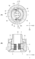
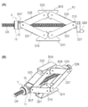
- (A) is a diagram showing a usage state of a fast-forward nut which is an example of this embodiment
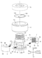
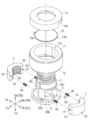
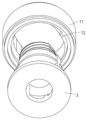
- (B) is a sectional view of (A). It is an exploded perspective view of the fast-forward nut which is an example of this embodiment. It is an exploded perspective view of the fast-forward nut which is an example of this embodiment. It is a perspective view for showing the detent which was formed in the tubular member. It is a perspective view of the bottom surface side of a cover member.
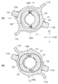
- (A) and (B) are cross-sectional views showing a screwed state of the fast-forward nut 1 and the round bar member CR.
- (A) and (B) are cross-sectional views showing the release state of the fast-forward nut 1 and the round bar member CR.
- FIG. 1 It is a figure which shows the use state of the fast-forward nut 101. It is an exploded perspective view of the fast-forward nut 101.
- (A) is a cross-sectional view showing a screwed state of the fast-forward nut 101 and the round bar member CR
- (B) is a cross-sectional view showing the release of the fast-forward nut 101 and the round bar member CR.
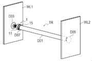
- This is an example of a tension rod TR incorporating the fast-forward nut 1 of the first embodiment, which is the fourth embodiment.
- (A) is a front view
- (B) is a perspective view.
- FIG. 1 (A) is a diagram showing a usage state of a fast-forward nut which is an example of the present embodiment
- FIG. 1 (B) is a cross-sectional view of FIG. 1 (A)
- FIGS. 2 and 3 are. It is an exploded perspective view of the fast-forward nut of this embodiment
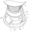
- FIG. 4 is a perspective view (only the tubular member 3 and the cover member 11 are shown) for showing the detent formed on the tubular member
- the fast-forward nut 1 of the present embodiment is used as an adjuster for adjusting the height of the object OB fixed to the fast-forward nut 1.
- a plurality of directions are defined with respect to the fast-forward nut 1. That is, the left-right direction (first direction D1) consisting of the right direction Ri and the left direction Le, the vertical direction (second direction D2) consisting of the upward direction Up and the downward direction Lo, and the front-rear direction consisting of the front direction Fo and the rear direction Re.
- the direction (third direction D3) is defined as shown in FIG. In other figures, the same direction as that used in the explanation of FIG. 2 is used.
- the fast-forward nut 1 is mainly positioned with a tubular member 3, a pair of half-split nut members 5, 7, elastic members 9A to 9D constituting the nut urging member, a cover member 11, and a torsion spring 13. It includes a member 15.
- the tubular member 3 is formed in the main body 17 having a through hole 23 through which the round bar member CR penetrates, and in the main body 17 so as to face the through hole 23 in the radial direction, and communicates with the through hole 23.
- the cover member 11 has a pair of window portions 19, 21 for partially accommodating the pair of half-split nut members 5, 7 so as to allow the pair of half-split nut members 5, 7 to slide in the radial direction. It is arranged so as to be rotatable relative to the cover member 11 inside the cover member 11. As shown in FIG. 4, around the tubular member 3, detents 4 and 4 are formed so that the cover member 11 rotates in a predetermined angle range.
- the pair of half-split nut members 5 and 7 are made of half-split nut members having the same shape, and have a female screw portion screwed with the male screw of the round bar member CR on the inner circumference, and the outer peripheral surface is inside the cover member 11. It has an arc shape including the part where the peripheral surface contacts.
- Flat portions 5A and 7A are formed on one side surface.
- Notches 5B and 7B guided by rail portions 20 and 22 formed on the tubular member 3 are formed on the lower surface.
- elastic member fixing holes 5E, 5F and 7E, 7F for fixing one end of the elastic members 9A to 9D are formed on the facing surfaces 5C, 5D and 7C, 7D facing the pair of partition walls 25, 27. ..
- the elastic member fixing holes 5F and 7F are also opened in the flat portions 5A and 7A.
- a pair of partition walls 25 and 27 are formed between the pair of window portions 19 and 21.
- Elastic members 9A to 9D constituting the nut urging member are arranged between the pair of partition walls 25 and 27 and the pair of half-split nut members 5 and 7, respectively.
- the pair of partition walls 25 and 27 are formed with bottomed elastic member fixing holes 29A to 29D for fixing one end of the elastic members 9A to 9D, and are formed on one surface of the pair of partition walls.
- the elastic member fixing holes 29A and 29B and the elastic member fixing holes 29C and 29D formed on the other surface facing the one surface are formed at positions deviated from each other in the extending direction in which the through hole 23 extends.
- Each of the pair of partition walls 25 and 27 is radially outward so that the inner peripheral surface of the cover member 11 does not come into contact with the nut urging members 9B and 9D when the cover member 11 is changed from the released state to the screwed state described later. It has extension wall portions 25A and 27A extending in the circumferential direction from the end wall, and flat surfaces 5A and 7A along the inner wall surface of the extension wall portion are formed on each of the pair of half nut members.
- the window portion 19 is formed at a position deviated from the window portion 21 by half a pitch of the female screw portions of the pair of half-split nut members 5 and 7 in the direction in which the through hole 23 extends.
- the cover member 11 is a tubular member that houses a pair of half-split nut members 5, 7 and nut urging members 9A to 9D.
- the contour shape of the inner peripheral surface of the cover member 11 is a long axis and a short axis in which the tubular member 3 in a state where the pair of half nut members 5 and 7 are housed in the pair of window portions 19 and 21 is housed. It has an elliptical shape.
- the contour shape of the outer peripheral surface is formed in a cylindrical shape.
- An engaging hole 11a for fixing the torsion spring 13 is formed on the surface of the cover member 11.
- a protrusion 12 that engages with the detent 4 of the tubular member 3 is formed inside the bottom surface of the cover member 11. By engaging the detent 4 and the protrusion 12, the cover member 11 rotates in a predetermined angle range around the tubular member 3.
- the torsion spring 13 is a coil-shaped spring in which one end 13A extends outward in the radial direction and the other end 13B extends in the direction in which the round bar member CR extends.
- the positioning member 15 is a member that is arranged so as not to rotate with respect to the tubular member 3 and positions the torsion spring 13 with respect to the cover member 11.
- a notch 15A is formed in the positioning member 15.
- One end 13A of the torsion spring 13 is fixed to the notch 15A of the positioning member 15, the other end 13B is fixed to the engagement hole 11a of the cover member 11, and the cover member 11 is unidirectionally relative to the tubular member 3. The energy is accumulated when the cover member 11 is relatively rotated to be released from the screwed state, and is released when the force for relatively rotating the cover member 11 in one direction is released.
- 6 (A) and 6 (B) are views showing the screwed state of the fast-forward nut 1 and the round bar member CR
- FIGS. 7 (A) and 7 (B) are the release of the fast-forward nut 1 and the round bar member CR. It is a figure which shows the state. 6 (A) is a sectional view taken along line AA of FIG. 6 (B), and FIG. 6 (B) is a sectional view taken along line BB of FIG. 6 (A).
- 7 (A) is a sectional view taken along line AA of FIG. 7 (B), FIG. 7 (B) is a sectional view taken along line BB of FIG. 7 (A).
- the round bar member CR is not shown in FIGS. 6 and 7.
- the cover member 11 is in a screwed state when no rotational force is applied (FIGS. 6A and 6B). ..
- the sliding direction (first direction) of the pair of half-split nut members 5 and 7 coincides with the direction in which the elliptical minor axis extends, and the inner peripheral surface of the cover member is a pair of half.
- the split nut member is pushed inward in the radial direction against the urging force of the nut urging member, and screwed with the female screw of the pair of half nut members and the male screw of the round bar member. It is in a state.
- the cover member 11 is rotated in one direction relative to the tubular member 3 (counterclockwise in FIG. 6A in the present embodiment), and the pair of half nut members 5
- the pair of half nut members 5 and 7 are railed by the release of the nut urging members 9A to 9D.
- Guided by the portions 20 and 22 and the extension wall portions 25A and 27A they slide away from the round bar member CR in the radial direction, and the female threads of the pair of half nut members 5 and 7 and the male threads of the round bar member CR
- the screw is completely released and the screw is released (FIGS. 7A and 7B).
- the cover member 11 When the force rotating the cover member 11 is removed from the released state, the cover member 11 is relatively in the opposite direction to the tubular member due to the action of the torsion spring 13 (FIG. 7 (A)).
- the inner peripheral surface of the cover member 11 is the pair of half nut members 5 until the sliding direction of the pair of half nut members 5 and 7 coincides with the direction in which the elliptical minor axis extends.
- 7 push the pair of half-split nut members 5, 7 inward in the radial direction against the urging force of the nut urging members 9A to 9D, and the pair of half-split nut members 5, 7 are the rail portions 20, 22.
- ⁇ Second Embodiment> 8 to 10 are fast-forward nuts of the second embodiment.
- the parts common to the first embodiment are designated by adding 100 to the reference numerals given in FIGS. 2 and 3, and the description thereof will be omitted.
- FIG. 8 is a diagram showing a usage state of the fast-forward nut 101
- FIG. 9 is an exploded perspective view of the fast-forward nut 101
- FIG. 10 (A) shows a screwed state of the fast-forward nut 101 and the round bar member CR
- 10 (B) is a cross-sectional view showing a state in which the fast-forward nut 101 and the round bar member CR are released.
- the cover member 111 is provided with the first finger hooks 111A and 111B extending radially outward from the outer peripheral surface, and the positioning member 115 is provided with the second finger hooks 115A and 115B. There is.
- the other finger With the finger resting on the second finger hook (115A or 115B), the other finger is placed on the first finger hook (111A when the second finger hook is 115A, and the second finger hook).
- 111B In the case of 115B, 111B) is operated so as to pull the first finger hook portion toward the second finger hook portion against the urging force of the torsion spring 113 (FIG. 10 (A)). It is configured to be in the released state (FIG. 10 (B)).
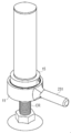
- FIG. 11 is a diagram showing a fast-forward nut according to the third embodiment.
- the third embodiment is an example in which the gripping lever 231 is provided on the cover member 11 of the fast-forward nut 1 of the first embodiment.
- the gripping lever 231 is directly fixed to the cover member 11 and extends outward in the radial direction.
- the gripping lever 231 allows the fast-forward nut to be operated from a distant position within reach.
- the grip lever 231 may cover the periphery of the cover member 11 and extend from a cylindrical portion fixed to the cover member 11.
- the fourth embodiment is an example of the tension rod TR incorporating the fast-forward nut 1 of the first embodiment shown in FIG.
- the tension rod TR is arranged between the two opposing wall surfaces WL1 and WL2.
- the tension rod TR is composed of a round rod member CR and a tubular body D01.
- the end portion of the round bar member CR has a first contact portion D03 that contacts the wall portion WL1.
- the tubular body D01 has a second contact portion D05 in contact with the wall portion WL2 at the end.
- An opening D07 through which the round bar member CR is inserted is formed at the other end, and the cover member 11 is fixed in a state where the cover member 11 is arranged so that the through holes 23 of the main body 17 of the fast-forward nut 1 are aligned. Has been done.
- the tension rod TR releases the fast-forward nut 1 and pushes the round bar member CR into the tubular body D01 or pulls it out from the tubular body D01 to cause the tension rod TR. Rough adjustment of length can be performed. Then, after the rough adjustment, the fast-forward nut 1 can be screwed and the round bar member CR can be rotated with respect to the tubular body D01 to finely adjust the length of the tension rod TR.
- the fifth embodiment is an example of the pantograph jack PJ incorporating the fast-forward nut 1 of the first embodiment shown in FIGS. 13A and 13B.
- the pantograph jack PJ includes a lower link mechanism D11, an upper link mechanism D13, a holding connecting portion D15, and an operating connecting portion D17.
- the lower link mechanism D11 is composed of a first pair of link arms D21 and D21 connected via a base D19
- the upper link mechanism D13 is a second pair of link arms connected via a receiving seat D23. It consists of D25 and D25.
- the lower link mechanism D11 and the upper link mechanism D13 are connected in a pantograph shape by the holding connecting portion D15 and the operating connecting portion D17.
- the round bar member CR having one end rotatably held by the holding connecting portion D15 so as not to move in the axial direction is screwed into the operating connecting portion D17, and the holding connecting portion D15 of the round bar member CR is screwed.
- the distance between the holding connecting portion D15 and the operating connecting portion D17 can be expanded or contracted so that the round bar member CR can be rotated by the rotation operating portion D29 attached to the protruding portion D27 protruding outward. ..
- the operating connecting portion D17 includes the fast-forward nut 1. Then, the round bar member CR is screwed into the operating connecting portion D17 by the pair of half-split nut members 5 and 7 of the fast-forward nut 1.
- the pantograph jack PJ moves the operating connecting portion D17 in the axial direction of the round bar member CR without rotating the rotation operation portion D29.
- the distance between the holding connecting portion D15 and the operating connecting portion D17 can be expanded or contracted. That is, in this state, the rough adjustment of the distance between the base D19 and the receiving seat D23 can be performed.
- the fast-forward nut 1 is brought into a screwed state, so that the rotation operation unit D29 can be rotated to finely adjust the distance between the base D19 and the receiving seat D23.
- fast-forward nut 101 of the second embodiment may be used for the tension rod of the fourth embodiment or the pantograph jack of the fifth embodiment.
- a fast-forward nut that can slide along a round bar member and can screw a male screw of the round bar member and a female screw of a pair of half-split nut members at any position on the round bar member.
- a fast-forward nut assembly incorporating the fast-forward nut can be provided.
Landscapes
- Life Sciences & Earth Sciences (AREA)
- Engineering & Computer Science (AREA)
- Geology (AREA)
- Mechanical Engineering (AREA)
- Structural Engineering (AREA)
- Transmission Devices (AREA)
Priority Applications (1)
| Application Number | Priority Date | Filing Date | Title |
|---|---|---|---|
| JP2021514861A JPWO2020213392A1 (cg-RX-API-DMAC7.html) | 2019-04-17 | 2020-03-31 |
Applications Claiming Priority (2)
| Application Number | Priority Date | Filing Date | Title |
|---|---|---|---|
| JP2019078810 | 2019-04-17 | ||
| JP2019-078810 | 2019-04-17 |
Publications (1)
| Publication Number | Publication Date |
|---|---|
| WO2020213392A1 true WO2020213392A1 (ja) | 2020-10-22 |
Family
ID=72836850
Family Applications (1)
| Application Number | Title | Priority Date | Filing Date |
|---|---|---|---|
| PCT/JP2020/014902 Ceased WO2020213392A1 (ja) | 2019-04-17 | 2020-03-31 | 早送りナット及び早送りナット組立品 |
Country Status (2)
| Country | Link |
|---|---|
| JP (1) | JPWO2020213392A1 (cg-RX-API-DMAC7.html) |
| WO (1) | WO2020213392A1 (cg-RX-API-DMAC7.html) |
Cited By (1)
| Publication number | Priority date | Publication date | Assignee | Title |
|---|---|---|---|---|
| JP2023177023A (ja) * | 2022-06-01 | 2023-12-13 | 愛三工業株式会社 | 締結構造体 |
Citations (5)
| Publication number | Priority date | Publication date | Assignee | Title |
|---|---|---|---|---|
| JPS4720530B1 (cg-RX-API-DMAC7.html) * | 1968-06-04 | 1972-06-10 | ||
| JPS57169794U (cg-RX-API-DMAC7.html) * | 1981-04-16 | 1982-10-26 | ||
| JPH0445473U (cg-RX-API-DMAC7.html) * | 1990-08-23 | 1992-04-17 | ||
| JP2000502434A (ja) * | 1996-10-09 | 2000-02-29 | スレッド テクノロジー インコーポレイテッド | ねじ付き連結部材の急速連結及び解除装置 |
| JP2019060360A (ja) * | 2017-09-25 | 2019-04-18 | 株式会社大里 | 早送りナット |
-
2020
- 2020-03-31 JP JP2021514861A patent/JPWO2020213392A1/ja active Pending
- 2020-03-31 WO PCT/JP2020/014902 patent/WO2020213392A1/ja not_active Ceased
Patent Citations (5)
| Publication number | Priority date | Publication date | Assignee | Title |
|---|---|---|---|---|
| JPS4720530B1 (cg-RX-API-DMAC7.html) * | 1968-06-04 | 1972-06-10 | ||
| JPS57169794U (cg-RX-API-DMAC7.html) * | 1981-04-16 | 1982-10-26 | ||
| JPH0445473U (cg-RX-API-DMAC7.html) * | 1990-08-23 | 1992-04-17 | ||
| JP2000502434A (ja) * | 1996-10-09 | 2000-02-29 | スレッド テクノロジー インコーポレイテッド | ねじ付き連結部材の急速連結及び解除装置 |
| JP2019060360A (ja) * | 2017-09-25 | 2019-04-18 | 株式会社大里 | 早送りナット |
Cited By (2)
| Publication number | Priority date | Publication date | Assignee | Title |
|---|---|---|---|---|
| JP2023177023A (ja) * | 2022-06-01 | 2023-12-13 | 愛三工業株式会社 | 締結構造体 |
| JP7690428B2 (ja) | 2022-06-01 | 2025-06-10 | 愛三工業株式会社 | 締結構造体 |
Also Published As
| Publication number | Publication date |
|---|---|
| JPWO2020213392A1 (cg-RX-API-DMAC7.html) | 2020-10-22 |
Similar Documents
| Publication | Publication Date | Title |
|---|---|---|
| US8534427B2 (en) | Movable desk | |
| US11185999B2 (en) | Folding knife with locking mechanism | |
| US8607491B2 (en) | Vertical fore grip with rotating and/or canting and/or tilting | |
| JP2018116278A (ja) | 表示画面の取り付け具の改良 | |
| US20170326015A1 (en) | Clamping claw for attaching to a slide rail of an operating table | |
| US9038306B2 (en) | Apparatus for mounting a sighting mechanism on a handgun | |
| US9578970B2 (en) | Pivoting articulation joint and piece of furniture provided with such | |
| US7290741B1 (en) | Furniture glide | |
| US8397362B2 (en) | Device for setting a fastener element | |
| EP0446566A1 (en) | A universal espagnolette handle for door and window fixtures | |
| SG188294A1 (en) | One-touch fitting device for fan | |
| JP5039181B2 (ja) | 扉開閉用レバーハンドル装置 | |
| JP6611927B2 (ja) | 家具金具 | |
| US10010746B1 (en) | Seat adjustment structure for exercise machine | |
| JP2020515370A (ja) | ダンス練習ポール用の端部アセンブリ | |
| TW202146180A (zh) | 扭力結構 | |
| JP6930730B2 (ja) | 早送りナット | |
| JP2017160724A (ja) | ラッチ錠 | |
| CN108835958B (zh) | 枪托装置及枪柜 | |
| JPS6145615Y2 (cg-RX-API-DMAC7.html) | ||
| JP7525890B2 (ja) | キャスタ装置 | |
| JP3936173B2 (ja) | 取付装置 | |
| WO2024228365A1 (ja) | 角度調整金具およびこれを用いたソファー | |
| US12618276B2 (en) | Furniture fitting having an adjustment mechanism | |
| JP2018059365A (ja) | ドアガードおよびドアガード装置 |
Legal Events
| Date | Code | Title | Description |
|---|---|---|---|
| 121 | Ep: the epo has been informed by wipo that ep was designated in this application |
Ref document number: 20790463 Country of ref document: EP Kind code of ref document: A1 |
|
| ENP | Entry into the national phase |
Ref document number: 2021514861 Country of ref document: JP Kind code of ref document: A |
|
| NENP | Non-entry into the national phase |
Ref country code: DE |
|
| 122 | Ep: pct application non-entry in european phase |
Ref document number: 20790463 Country of ref document: EP Kind code of ref document: A1 |