WO2020209244A1 - モータユニット - Google Patents
モータユニット Download PDFInfo
- Publication number
- WO2020209244A1 WO2020209244A1 PCT/JP2020/015621 JP2020015621W WO2020209244A1 WO 2020209244 A1 WO2020209244 A1 WO 2020209244A1 JP 2020015621 W JP2020015621 W JP 2020015621W WO 2020209244 A1 WO2020209244 A1 WO 2020209244A1
- Authority
- WO
- WIPO (PCT)
- Prior art keywords
- motor
- inverter
- case
- housing
- case portion
- Prior art date
- Legal status (The legal status is an assumption and is not a legal conclusion. Google has not performed a legal analysis and makes no representation as to the accuracy of the status listed.)
- Ceased
Links
Images



Classifications
-
- B—PERFORMING OPERATIONS; TRANSPORTING
- B60—VEHICLES IN GENERAL
- B60K—ARRANGEMENT OR MOUNTING OF PROPULSION UNITS OR OF TRANSMISSIONS IN VEHICLES; ARRANGEMENT OR MOUNTING OF PLURAL DIVERSE PRIME-MOVERS IN VEHICLES; AUXILIARY DRIVES FOR VEHICLES; INSTRUMENTATION OR DASHBOARDS FOR VEHICLES; ARRANGEMENTS IN CONNECTION WITH COOLING, AIR INTAKE, GAS EXHAUST OR FUEL SUPPLY OF PROPULSION UNITS IN VEHICLES
- B60K17/00—Arrangement or mounting of transmissions in vehicles
- B60K17/04—Arrangement or mounting of transmissions in vehicles characterised by arrangement, location or kind of gearing
- B60K17/16—Arrangement or mounting of transmissions in vehicles characterised by arrangement, location or kind of gearing of differential gearing
-
- H—ELECTRICITY
- H02—GENERATION; CONVERSION OR DISTRIBUTION OF ELECTRIC POWER
- H02K—DYNAMO-ELECTRIC MACHINES
- H02K11/00—Structural association of dynamo-electric machines with electric components or with devices for shielding, monitoring or protection
- H02K11/30—Structural association with control circuits or drive circuits
- H02K11/33—Drive circuits, e.g. power electronics
-
- H—ELECTRICITY
- H02—GENERATION; CONVERSION OR DISTRIBUTION OF ELECTRIC POWER
- H02K—DYNAMO-ELECTRIC MACHINES
- H02K7/00—Arrangements for handling mechanical energy structurally associated with dynamo-electric machines, e.g. structural association with mechanical driving motors or auxiliary dynamo-electric machines
- H02K7/14—Structural association with mechanical loads, e.g. with hand-held machine tools or fans
-
- Y—GENERAL TAGGING OF NEW TECHNOLOGICAL DEVELOPMENTS; GENERAL TAGGING OF CROSS-SECTIONAL TECHNOLOGIES SPANNING OVER SEVERAL SECTIONS OF THE IPC; TECHNICAL SUBJECTS COVERED BY FORMER USPC CROSS-REFERENCE ART COLLECTIONS [XRACs] AND DIGESTS
- Y02—TECHNOLOGIES OR APPLICATIONS FOR MITIGATION OR ADAPTATION AGAINST CLIMATE CHANGE
- Y02T—CLIMATE CHANGE MITIGATION TECHNOLOGIES RELATED TO TRANSPORTATION
- Y02T10/00—Road transport of goods or passengers
- Y02T10/60—Other road transportation technologies with climate change mitigation effect
- Y02T10/64—Electric machine technologies in electromobility
Definitions
- the present invention relates to a motor unit.
- the present application claims priority based on Japanese Patent Application No. 2019-075799 filed on April 11, 2019, the contents of which are incorporated herein by reference.
- a drive device in which an inverter case is attached to a drive device case is known.
- the drive device of Patent Document 1 has a structure in which an inverter is fixed to a top wall via a support and a control device is fixed to a mounting portion.
- the vibration of the motor housing is transmitted to the inverter case, and the inverter case itself deforms and vibrates, which may cause noise.
- One aspect of the present invention is intended to reduce noise caused by an inverter case.
- the motor unit controls a motor having a rotor rotatable about a motor shaft, a stator located radially outside the rotor, and a current supplied to the motor. It includes an inverter and an inverter case for accommodating the inverter.
- the inverter case has a first case portion and a second case portion.
- the first case portion and the second case portion each have a flange portion.
- the first case portion and the second case portion are fixed by the flange portion.
- At least one of the first case portion and the second case portion has ribs extending toward the respective flange portions.
- a motor unit capable of realizing miniaturization is provided.
- FIG. 1 is a perspective view of the motor unit of one embodiment.
- FIG. 2 is a perspective view of the other side of the motor housing of one embodiment.
- FIG. 3 is a one-side perspective view of the motor housing of one embodiment.
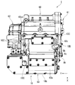
- FIG. 4 is a side view of the motor unit of one embodiment.
- FIG. 5 is a side sectional view of the motor unit of one embodiment.
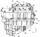
- FIG. 6 is a top perspective view of the motor unit of one embodiment.
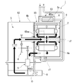
- FIG. 7 is a schematic configuration diagram of the motor unit of one embodiment.
- FIG. 8 is a side perspective view of the motor unit having the rib configuration of the modified example.
- the direction of gravity will be defined based on the positional relationship when the motor unit 1 is mounted on a vehicle located on a horizontal road surface.
- the XYZ coordinate system is shown as a three-dimensional Cartesian coordinate system as appropriate.
- the Z-axis direction indicates the vertical direction (that is, the vertical direction)
- the + Z direction is the upper side (opposite the gravity direction)
- the ⁇ Z direction is the lower side (gravity direction).
- the X-axis direction is a direction orthogonal to the Z-axis direction and indicates a front-rear direction of the vehicle on which the motor unit 1 is mounted.
- the Y-axis direction is a direction orthogonal to both the X-axis direction and the Z-axis direction, and indicates the width direction (left-right direction) of the vehicle.
- the direction parallel to the motor shaft J2 of the motor 2 (Y-axis direction) is simply referred to as "axial direction”, and the radial direction centered on the motor shaft J2 is simply referred to as “diametrical direction”.
- the circumferential direction centered on the motor shaft J2, that is, the circumference of the motor shaft J2 is simply referred to as the "circumferential direction”.
- the "one side in the axial direction” is the positive side in the Y-axis direction (the Y1 side shown in FIGS. 1 and 3), and the “other side in the axial direction” is the negative side in the Y-axis direction (the other side in the Y-axis direction). (Y2 side shown in FIG. 2).
- extending along a predetermined direction means that in addition to the case where it extends in a strictly predetermined direction, it is tilted in a range of less than 45 ° with respect to the exact direction. Including the case of extending in the direction.
- the motor unit 1 is mounted on a vehicle powered by a motor, such as a hybrid electric vehicle (HEV), a plug-in hybrid electric vehicle (PHV), and an electric vehicle (EV), and is used as the power source thereof. That is, the motor unit 1 is a drive device.
- a motor such as a hybrid electric vehicle (HEV), a plug-in hybrid electric vehicle (PHV), and an electric vehicle (EV)
- the motor unit 1 will be described with reference to FIGS. 1 to 7.
- the motor unit 1 includes a motor (main motor) 2, a gear portion 3 including a speed reducer 4 and a differential device 5, a housing 6, an oil O housed in the housing 6, and the like. It includes an inverter 8 and an oil pump 9.
- Oil O is a medium that circulates inside the motor.
- another fluid such as water may be used as a medium. That is, the pump described later may be an oil-cooled pump or a water-cooled pump.
- a storage space for accommodating the motor 2, the gear portion 3, and the inverter 8 is provided inside the housing 6.
- the housing 6 holds the motor 2, the gear portion 3, and the inverter 8 in the accommodation space.
- the motor 2 is housed in the housing 6.
- the motor 2 includes a rotor that rotates about a motor shaft J2 that extends in the horizontal direction, a stator that is located radially outside the rotor, and a pair of bearings that rotatably support the rotor.
- the motor 2 of this embodiment is an inner rotor type motor.
- the rotor rotates when an alternating current is supplied from the battery (not shown) to the stator via the inverter 8.
- the rotor has a shaft, a rotor core, and a plurality of rotor magnets.
- the rotor ie, shaft, rotor core and rotor magnet
- the torque of the rotor is transmitted to the gear portion 3.
- the shaft extends along the axial direction around the motor shaft J2.
- the shaft rotates about the motor shaft J2.
- the gear portion 3 is housed in the housing 6.
- the gear portion 3 is connected to the shaft on one side in the axial direction of the motor shaft J2.
- the gear unit 3 has a speed reducing device 4 and a differential device 5.
- the torque output from the motor 2 is transmitted to the differential device 5 via the speed reducer 4.
- the speed reducer 4 is connected to the rotor of the motor 2.
- the speed reduction device has a function of reducing the rotation speed of the motor 2 and increasing the torque output from the motor 2 according to the reduction ratio.
- the speed reducing device 4 transmits the torque output from the motor 2 to the differential device 5.
- the differential device 5 is connected to the motor 2 via the speed reducer 4.
- the differential device 5 is a device for transmitting the torque output from the motor 2 to the wheels of the vehicle.
- the differential device 5 is connected to an axle that extends along the central axis J1.
- the differential device 5 has a function of transmitting the same torque to the axles of both the left and right wheels while absorbing the speed difference between the left and right wheels when the vehicle turns.
- the housing 6 includes a motor housing 60, a motor cover 61, a gear housing 62, and an inverter housing 63.
- the motor housing 60 accommodates a motor accommodating portion 6a having a motor chamber for accommodating the motor 2 inside, a gear accommodating portion 6b having a gear chamber for accommodating the gear portion 3 inside, a part of the inverter 8 and a connecting line. It has an inverter accommodating portion 6c having an inverter chamber inside.
- the inverter accommodating portion 6c accommodates a connection line connecting the inverter 8 and the motor 2 and a part of the inverter 8. Further, the inverter accommodating portion 6c of the motor housing 60 may accommodate only the connecting line without the inverter 8.
- the motor housing 60 includes a tubular peripheral wall portion 60a that surrounds the motor 2 from the outside in the radial direction, a first side plate portion 60b located on the other side (Y2 side in the drawing) of the peripheral wall portion 60a in the axial direction, and an axial direction of the peripheral wall portion 60a.
- the second side plate portion 60c located on one side (Y1 side in the drawing), the first connecting plate portion 60d that connects the first side plate portion 60b and the second side plate portion 60c and faces the rear (-X side) of the vehicle, and the first The second connecting plate 60e that connects the one side plate 61b and the second side plate 60c and faces upward (+ Z side) in the direction of gravity, and the first side plate 61b and the second side plate extending upward from the peripheral wall 60a. It has a third connecting plate portion 60g that connects the portions 60c.
- the first side plate portion 60b has a first partition wall 60ba, a first protruding portion 60bb, and a motor flange portion 60bc.
- the motor flange portion 60bc surrounds the opening on the other side in the axial direction of the peripheral wall portion 60a and the periphery of the first partition wall 60ba.
- the first protruding portion 60bb protrudes radially outward (rear side of the vehicle; ⁇ X side) from the motor flange portion 60bc.
- the second side plate portion 60c has a second partition wall 60ca, a second overhanging portion 60cc, a second protruding portion 60cc, and a gear flange portion 60cd.
- the gear flange portion 60cd surrounds the second partition wall 60ca and the second overhanging portion 60cc.
- the second protruding portion 60cc projects upward (+ Z side) from the gear flange portion 60cd.
- the second partition wall 60ca has a partition wall opening 68 through which the shaft of the motor 2 is passed.
- the second partition wall 60ca has a recess 69 that opens on one surface of the second partition wall 60ca in the axial direction.
- the bearing of the gear portion 3 is housed in the recess 69.
- the motor housing 60 has a second partition wall 60ca that divides the internal accommodation space into a motor chamber and a gear chamber.
- the motor housing 60 has a second overhanging portion 60cc that projects from the second partition wall 60ca to the rear side of the vehicle.
- the second partition wall 60ca and the second overhanging portion 60cc form a part of the second side plate portion 60c.
- the accommodation space of the motor housing 60 is divided into a motor chamber and an inverter chamber by a peripheral wall portion 60a and a first partition wall 60ba.
- the first partition wall 60ba constitutes a part of the first side plate portion 60b.
- the motor cover 61 is fixed to the outside (Y2 side) of the first side plate portion 60b.
- the second partition wall 60ca, the peripheral wall portion 60a, and the motor cover 61 form a motor chamber, surround the motor, and house the motor. That is, the motor accommodating portion 6a is formed by the second partition wall 60ca and the peripheral wall portion 60a.
- the motor accommodating portion 6a has a cylindrical shape that opens on the other side in the axial direction. The opening of the motor accommodating portion 6a is covered by the motor cover 61 facing the second partition wall 60ca.
- the motor housing 60 has a motor flange portion 60bc connected to the motor cover 61. The motor flange portion 60bc projects to the other side in the axial direction with respect to the first partition wall 60ba.
- the second partition wall 60ca, the second overhanging portion 60cc, and the gear housing 62 form a gear chamber, surround the gear portion 3, and accommodate the gear portion 3. That is, the gear accommodating portion 6b is formed by the second partition wall 60ca and the second overhanging portion 60cc.
- the motor housing 60 has a gear flange portion 60cd connected to the gear housing 62. The gear flange portion 60cd projects on one side in the axial direction with respect to the second side plate portion 60c.
- a part of the peripheral wall portion 60a, the second protruding portion 60cc, the first side plate portion 60b, the first connecting plate portion 60d, the second connecting plate portion 60e, the third connecting plate portion 60g, and the inverter housing 63 constitute an inverter chamber. Then, the inverter 8 is surrounded and the inverter 8 is housed. That is, the peripheral wall portion 60a, the second protruding portion 60cc, the first side plate portion 60b, the first connecting plate portion 60d, the second connecting plate portion 60e, and the third connecting plate portion 60g form the inverter accommodating portion 6c shown in FIG. Constitute.
- the inverter accommodating portion 6c has a bottomed square tube shape that opens upward in the direction of gravity.
- the opening of the inverter accommodating portion 6c is covered by the inverter housing 63 which faces the second connecting plate portion 60e and the peripheral wall portion 60a in the vertical direction.
- the motor housing 60 has an inverter flange portion 60f connected to the inverter housing 63.
- the inverter flange portion 60f is located at the open end portion of the inverter housing portion 6c.
- the inverter flange portion 60f is a flange-shaped portion extending outward from the inverter housing portion 6c.
- the motor housing 60 has an inverter flange portion 60f.
- the inverter flange portion 60f is inclined when viewed from the vehicle width direction (Y-axis direction). That is, the inverter flange portion 60f is inclined with respect to the second connection plate portion 60e.
- the inverter flange portion 60f is connected to the inverter housing 63.
- the motor housing 60 is provided with an axle passage hole 67 through which a drive shaft (not shown) that supports the wheels passes.
- the gear housing 62 is fixed to the gear flange portion 60cd.
- the shape of the gear housing 62 is a concave shape that opens on the other side in the axial direction.
- the opening of the gear housing 62 is covered with the second side plate portion 60c.
- the space between the gear housing 62 and the second side plate portion 60c constitutes a gear chamber for accommodating the gear portion 3.
- the inverter housing 63 is mounted integrally with the motor housing 60. More specifically, the inverter housing 63 is mounted integrally with the motor accommodating portion 6a.
- the inverter housing 63 has a main body accommodating portion 63a and a mounting flange portion 63c.
- the main body accommodating portion 63a projects in the Z-axis direction with respect to the mounting flange portion 63c. That is, the main body accommodating portion 63a overlaps with the inverter accommodating portion 6c when viewed from the direction orthogonal to the motor shaft J2.
- the inverter housing 63 is fixed by the mounting flange portion 63c and the inverter flange portion 60f.
- the opening of the main body accommodating portion 63a is covered with the peripheral wall portion 60a and the second connecting plate portion 60e.
- the space between the inverter housing 63 and the motor housing 60 constitutes an inverter chamber for accommodating the inverter 8.
- the inverter 8 is electrically connected to the motor.
- the inverter 8 controls the current supplied to the motor.
- the inverter housing 63 is provided with an inverter 8 and a cooling water channel 8b through which cooling water for cooling the inverter is passed.
- the inverter 8 has a control element that controls the electric power supplied to the motor.
- the control element is, for example, an IGBT.
- the inverter housing 63 is a plate-shaped portion that extends in the horizontal direction.
- the top surface of the top wall 8c in the direction of gravity is flat.
- the mounting flange portion 63c of the inverter housing 63 and the inverter flange portion 60f of the motor housing 60 overlap.
- the mounting flange portion 63c and the inverter flange portion 60f are in surface contact with each other.
- a screw hole is provided in the inverter flange portion 60f.
- the mounting flange portion 63c and the inverter flange portion 60f are fixed via the bolt fastening portion 10C.
- the space between the inverter housing 63 and the inverter flange portion 60f is sealed with a sealing member (not shown) such as resin so that foreign matter does not enter between the inverter housing 63 and the inverter flange portion 60f. Therefore, the inverter housing 63 and the inverter flange portion 60f do not have to be in direct contact with each other.
- the shape of the inverter flange portion 60f is a quadrangular shape when viewed from the upper side in the direction of gravity.
- a part of the inverter 8 is located inside the inverter accommodating portion 6c.
- a part of the inverter 8 is located below the upper end of the inverter flange portion 60f in the gravity direction and inside the frame-shaped portion of the inverter accommodating portion 6c seen from the upper side in the gravity direction.
- the cooling water channel 8b is supported by the inverter housing 63.
- a part of the cooling water channel 8b and the main body accommodating portion 63a of the inverter housing 63 are a part of a single member. If the portion covering the inverter 8 is box-shaped, the wall surface of the box tends to vibrate.
- the inverter housing 63 support the cooling water channel 8b as in the above configuration, the weight of the cooling water channel 8b can be added to the top wall 8c of the inverter housing 63. Further, when there is cooling water in the cooling water channel 8b, the weight of the volume of the cooling water channel 8b can be added to the top wall 8c.
- the cooling water channel 8b crosses the top wall 8c when viewed from the upper side in the direction of gravity, the same effect as providing the rib on the top wall 8c can be obtained. As a result, the top wall 8c can be made difficult to vibrate.
- a part of the peripheral wall portion 60a, the second protruding portion 60cc, the first side plate portion 60b, the first connecting plate portion 60d, the second connecting plate portion 60e, the third connecting plate portion 60g, and the inverter housing 63 are , Inverter chamber is configured, the inverter 8 is surrounded, and the inverter 8 is housed. That is, a part of the peripheral wall portion 60a, the second protruding portion 60cc, the first side plate portion 60b, the first connecting plate portion 60d, the second connecting plate portion 60e, the third connecting plate portion 60g, and the inverter housing 63 are an inverter case. Consists of 10.
- a part of the peripheral wall portion 60a, the second protruding portion 60cc, the first side plate portion 60b, the first connecting plate portion 60d, the second connecting plate portion 60e, and the third connecting plate portion 60g are configured separately from the motor housing 60. You may. That is, the inverter case 10 may be configured separately from the motor housing 60.
- the inverter case 10 is composed of a first case portion 10a and a second case portion 10b.
- the first case portion 10a is composed of a part of the peripheral wall portion 60a, a second protruding portion 60cc, a first side plate portion 60b, a first connecting plate portion 60d, a second connecting plate portion 60e, and a third connecting plate portion 60g.
- the second case portion 10b is an inverter housing 63.
- the first case portion 10a and the second case portion 10b each have a flange portion.
- the first case portion 10a and the second case portion 10b are connected to each other via their respective flange portions.
- the flange portion of the first case portion 10a is the mounting flange portion 63c
- the flange portion of the second case portion 10b is the inverter flange portion 60f.
- the first case portion 10a and the second case portion 10b are fastened and fixed by a plurality of bolts 13 which are fastening members.
- the inverter case 10 is provided with ribs 11 on the inverter housing 63 and the first connection plate portion 60d of the motor housing 60.
- the rib 11 extends in the vertical direction from the upper end portion of the main body accommodating portion 63a toward the mounting flange portion 63c.
- the rib 11 extends in the vertical direction from the lower end portion of the first connecting plate portion 60d toward the inverter flange portion 60f.
- the mounting flange portion 63c and the inverter flange portion 60f have higher rigidity than the peripheral flat surface portions (first connection plate portion 60d, main body housing portion 63a).
- the ribs 11 may be provided alternately in the inverter housing 63 and the first connection plate portion 60d in the direction in which the flange portion of the inverter case 10 extends.
- the inverter case 10 has a flat surface portion 10A facing the vehicle rear side at an end portion on the vehicle rear side ( ⁇ X side). Since the inverter case 10 is connected to the peripheral wall portion 60a that houses the motor 2, vibration caused by the rotational operation of the motor 2 is transmitted to the flat surface portion 10A of the inverter case 10. The vibration causes the flat surface portion 10A of the inverter case 10 to vibrate. In particular, the central portion of the flat surface portion 10A as seen from the rear side of the vehicle vibrates significantly.
- a flange portion 10B (mounting flange portion 63c and an inverter flange portion 60f) extending in the horizontal direction is provided at the central portion in the vertical direction of the flat surface portion 10A.
- the rib 11 is extended in the vertical direction toward the flange portion 10B, and the rib 11 and the flange portion 10B are connected to each other, so that the rigidity can be further increased. As a result, the vibration of the inverter case 10 can be further suppressed.
- the rib 11 is provided on one or both of the left and right sides of the bolt fastening portion 10C in which the mounting flange portion 63c and the inverter flange portion 60f are fastened by the bolt 13.
- the portion near the bolt fastening portion 10C has a high surface pressure on the sealing surface due to the bolt fastening, resulting in high rigidity. Therefore, by providing the rib 11 in the vicinity of the bolt 13, the rib 11 can be extended to the periphery from a position having high rigidity, and the rigidity of the entire flat surface portion 10A can be effectively increased. By increasing the rigidity of the flat surface portion 10A, vibration of the inverter case 10 can be suppressed.
- the method of fastening the flange portion 10B is not limited to bolts, and other fastening methods such as rivets may be used as long as the rigidity of the rib 11 can be increased.
- the ribs 11a near the center of the flat surface portion 10A are provided alternately on the inverter housing 63 side and the motor housing 60 side along the direction (horizontal direction) in which the flange portion 10B of the inverter case 10 extends, so that the number of ribs 11a is small. The rigidity can be effectively increased.
- five ribs 11 are arranged on the inverter housing 63 side of the flange portion 10B, and five ribs 11 are arranged on the motor housing 60 side.
- the inverter housing 63 side and the motor The same number of ribs 11 may be provided on the housing 60 side.
- the ribs 11 on the inverter housing 63 side and the ribs 11 on the motor housing 60 side may be arranged in the vertical direction.
- the rib 11 is provided on the flat surface of the inverter case 10 opposite to the motor 2. This is because the inverter case 10 has a large flat surface portion 10A on the surface of the inverter case 10 opposite to the motor 2, so that the inverter case 10 is easily affected by vibration, and the vibration suppressing effect of the rib 11 is more effective. Further, in the inverter case 10, the end portion on the vehicle front side (+ X side) is connected to the peripheral wall portion 60a, and both sides in the vehicle width direction (Y-axis direction) are fixed to the motor cover 61 via the motor flange portion 60bc. By being fixed to the gear housing 62 via the gear flange portion 60cd, it is easy to secure the rigidity.
- the rib 11 provided on the surface (flat surface portion 10A) of the inverter case 10 opposite to the motor 2 is effective in suppressing vibration. Further, when the first case portion 10a of the inverter case 10 is connected only to the peripheral wall portion 60a, the inverter case 10 is cantileveredly supported by the motor housing 60. In this case, the vibration tends to increase in the flat surface portion 10A located at the position farthest from the connecting portion between the inverter case 10 and the peripheral wall portion 60a. Therefore, it is more effective to have the inverter case 10 provided with the rib 11.
- the first case portion 10a is a part of the motor housing 60.
- the vibration of the motor 2 is easily transmitted to the inverter case 10.
- a configuration in which the rib 11 is provided on the flat surface portion 10A of the inverter case 10 is particularly effective for suppressing vibration.
- the first case portion 10a which is a part of the motor housing 60, is located on the vehicle rear side of the peripheral wall portion 60a. That is, the first case portion 10a is arranged adjacent to the motor 2 in the horizontal direction (vehicle front-rear direction). According to this configuration, the inverter case 10 is less likely to protrude from the upper part to the upper side or from the lower part to the lower side of the motor unit 1. Therefore, it is possible to prevent the length of the motor unit 1 from increasing in the vertical direction.
- the second case portion 10b (inverter housing 63) is located on the vehicle rear side (-X side) of the upper portion of the motor housing 60. That is, the second case portion 10b is arranged at a position overlapping the motor housing 60 when viewed from the front-rear direction of the vehicle. According to this configuration, the portion of the second case portion 10b located above the motor housing 60 is reduced. The length of the motor unit 1 in the vertical direction can be shortened. When viewed from the front-rear direction of the vehicle, the entire second case portion 10b may be configured to overlap the motor housing 60. According to this configuration, since the second case portion 10b does not protrude upward from the motor housing 60, the length of the motor unit 1 in the vertical direction can be further shortened.
- the oil pump 9 is supported by the motor housing 60 in a cantilevered manner.
- the motor housing 60 has a tubular portion 60h for accommodating the oil pump 9.
- the tubular portion 60h is connected to the outer peripheral surface of the peripheral wall portion 60a on its outer peripheral surface.
- the end of the tubular portion 60h on one side (+ Y side) in the axial direction is connected to the second overhanging portion 60cc. That is, the oil pump 9 which is an auxiliary machine is supported at a position where it protrudes radially outward from the peripheral wall portion 60a of the motor housing 60.
- auxiliary machine such as the oil pump 9
- the motor housing 60 When an auxiliary machine such as the oil pump 9 is supported by the motor housing 60 in a substantially cantilevered state, vibration is generated due to the shaking of the heavy-weight auxiliary machine. Vibration caused by auxiliary equipment may be transmitted to the inverter case 10 and cause vibration. In such a case, providing the rib 11 on the inverter case 10 is particularly effective in suppressing vibration.
- FIG. 8 is a partial perspective view of a motor unit including an inverter case of a modified example.
- the arrangement of the ribs on the flat surface portion 10A facing the rear side of the vehicle is different from the configuration of the embodiment shown in FIG.
- the inverter case 10 of the modified example has a flange portion 10B that horizontally crosses the flat surface portion 10A.
- the flange portion 10B has a plurality of bolt fastening portions 10C arranged in a direction in which the flange portion 10B extends.
- the flange portion 10B has four bolt fastening portions 10C. Two of the bolt fastening portions 10C are arranged at the left and right ends of the flat surface portion 10A, respectively. Note that in FIG. 8, the bolt 13 for fastening the mounting flange portion 63c and the inverter flange portion 60f is not shown.
- the inverter case 10 of the modified example has a plurality of ribs 11A extending downward from the upper end portion of the second case portion 10b and connected to the upper surface of the flange portion 10B on the flat surface portion 10A, and the lower end of the first case portion 10a. It has a plurality of ribs 11B and a plurality of ribs 11C extending upward from the portion and connected to the lower portion of the flange portion 10B, and a plurality of ribs 11D extending in a direction intersecting the plurality of ribs 11B and the plurality of ribs 11C.
- the plurality of ribs 11A connect the upper surface of the mounting flange portion 63c to the surface of the main body accommodating portion 63a facing the vehicle rear side.
- the plurality of ribs 11A extend in the vertical direction.
- the inverter case 10 has seven ribs 11A. Six of the ribs 11A extend upward from a position adjacent to the bolt fastening portion 10C. According to this configuration, the rib 11A is connected to the bolt fastening portion 10C, which is a highly rigid portion of the flange portion 10B, so that the rigidity of the surface of the main body accommodating portion 63a facing the vehicle rear side is increased and vibration is effective. Can be suppressed.
- One of the seven ribs 11A extends upward from the central portion of the mounting flange portion 63c in the vehicle width direction (left-right direction).
- the present embodiment since there is a relatively wide flat surface portion in the left-right direction central portion on the surface of the main body accommodating portion 63a facing the vehicle rear side, one of the ribs 11A is arranged in the left-right direction central portion. Vibration can be suppressed more effectively.
- the plurality of ribs 11B connect the inverter flange portion 60f and the surface of the first connecting plate portion 60d facing the vehicle rear side.
- the lower ends of the plurality of ribs 11B reach the lower ends of the surface of the first connecting plate portion 60d facing the vehicle rear side.
- the inverter case 10 has eight ribs 11B. Two ribs 11B are arranged for each bolt fastening portion 10C. That is, at each of the four bolt fastening portions 10C, the upper ends of the ribs 11B are connected to both ends of the bolt fastening portion 10C in the left-right direction.
- the rigidity of the first connecting plate portion 60d can be increased by connecting the rib 11B to the bolt fastening portion 10C which is a highly rigid portion of the flange portion 10B. Further, since the two ribs 11B extend from one bolt fastening portion 10C, the arrangement density of the ribs 11B on the surface of the first connecting plate portion 60d becomes high. Therefore, vibration can be suppressed in a wide range of the first connection plate portion 60d.
- the plurality of ribs 11C connect the inverter flange portion 60f and the surface of the first connecting plate portion 60d facing the vehicle rear side.
- the inverter case 10 has three ribs 11C.
- the rib 11C is arranged between two bolt fastening portions 10C adjacent to each other in the left-right direction.
- the rib 11C has a width larger than that of the rib 11B. According to this configuration, the rigidity of the region located between the ribs 11B extending from the bolt fastening portion 10C can be increased.
- the rib 11C is a rib that is not connected to the bolt fastening portion 10C, but since it is a rib having a width larger than that of the rib 11B, the rigidity of the first connecting plate portion 60d can be sufficiently increased.
- the plurality of ribs 11D are arranged at the central portion and the lower end portion in the vertical direction of the first connecting plate portion 60d. That is, the inverter case 10 has two ribs 11D. One rib 11D intersects the vertical central portion of the rib 11B and the rib 11C. The other rib 11D intersects the lower ends of the rib 11B and the rib 11C.
Landscapes
- Engineering & Computer Science (AREA)
- Power Engineering (AREA)
- Microelectronics & Electronic Packaging (AREA)
- Chemical & Material Sciences (AREA)
- Combustion & Propulsion (AREA)
- Transportation (AREA)
- Mechanical Engineering (AREA)
- Motor Or Generator Frames (AREA)
Abstract
モータユニットは、モータ軸を中心として回転可能なロータおよびロータの径方向外側に位置するステータを有するモータと、モータに供給される電流を制御するインバータと、インバータを収容するインバータケースと、を備える。インバータケースは、第1ケース部と第2ケース部と、を有する。第1ケース部及び第2ケース部は、それぞれフランジ部を有する。第1ケース部と第2ケース部とは、フランジ部により固定される。第1ケース部又は第2ケース部の少なくとも一方は、それぞれのフランジ部に向かって延びるリブを有する。
Description
本発明は、モータユニットに関する。本願は、2019年4月11日に出願された日本国特許出願第2019-075799号に基づき優先権を主張し、その内容をここに援用する。
インバータケースが駆動装置ケースに対して取り付けられた駆動装置が知られている。特許文献1の駆動装置は、インバータが支持体を介して頂壁に固定され、制御装置が取付部に固定される構造を備えている。
従来のインバータケースをモータハウジングに取り付ける場合、モータハウジングの振動がインバータケースに伝わり、インバータケース自体が変形して振動し、騒音の原因となる場合がある。
本発明の一つの態様は、インバータケースに起因する騒音を低減することを目的の一つとする。
本発明のモータユニットの一つの態様において、モータユニットは、モータ軸を中心として回転可能なロータおよび前記ロータの径方向外側に位置するステータを有するモータと、前記モータに供給される電流を制御するインバータと、前記インバータを収容するインバータケースと、を備える。前記インバータケースは、第1ケース部と第2ケース部と、を有する。前記第1ケース部及び前記第2ケース部は、それぞれフランジ部を有する。前記第1ケース部と前記第2ケース部とは、前記フランジ部により固定される。前記第1ケース部又は第2ケース部の少なくとも一方は、それぞれのフランジ部に向かって延びるリブを有する。
本発明の一つの態様によれば、小型化を実現できるモータユニットが提供される。
以下、図面を参照しながら、本発明の実施形態に係るモータユニットについて説明する。なお、本発明の範囲は、以下の実施の形態に限定されず、本発明の技術的思想の範囲内で任意に変更可能である。
以下の説明では、モータユニット1が水平な路面上に位置する車両に搭載された場合の位置関係を基に、重力方向を規定して説明する。また、図面においては、適宜3次元直交座標系としてXYZ座標系を示す。XYZ座標系において、Z軸方向は、鉛直方向(すなわち上下方向)を示し、+Z方向が上側(重力方向の反対側)であり、-Z方向が下側(重力方向)である。また、X軸方向は、Z軸方向と直交する方向であってモータユニット1が搭載される車両の前後方向を示す。Y軸方向は、X軸方向とZ軸方向との両方と直交する方向であって、車両の幅方向(左右方向)を示す。
以下の説明において特に断りのない限り、モータ2のモータ軸J2に平行な方向(Y軸方向)を単に「軸方向」と呼び、モータ軸J2を中心とする径方向を単に「径方向」と呼び、モータ軸J2を中心とする周方向、すなわち、モータ軸J2の軸周りを単に「周方向」と呼ぶ。本実施形態では、「軸方向一方側」は、Y軸方向の正の側(図1および図3に示すY1側)であり、「軸方向他方側」は、Y軸方向の負の側(図2に示すY2側)である。
また、本明細書において、所定の方向(又は平面)に「沿って延びる」とは、厳密に所定の方向に延びる場合に加えて、厳密な方向に対して、45°未満の範囲で傾いた方向に延びる場合も含む。
以下、本発明の例示的な一実施形態に係るモータユニット1について説明する。本実施形態のモータユニット1は、ハイブリッド自動車(HEV)、プラグインハイブリッド自動車(PHV)、電気自動車(EV)等、モータを動力源とする車両に搭載され、その動力源として使用される。すなわち、モータユニット1は駆動装置である。
図1から図7を用いてモータユニット1を説明する。
モータユニット1は、図7に示すように、モータ(メインモータ)2と、減速装置4および差動装置5を含むギヤ部3と、ハウジング6と、ハウジング6内に収容されるオイルOと、インバータ8と、オイルポンプ9を備える。オイルOはモータ内部を循環する媒体である。なお、オイルOの代わりに水などの別の流体を媒体としても良い。すなわち、後述するポンプは油冷ポンプであっても水冷ポンプであっても良い。
モータユニット1は、図7に示すように、モータ(メインモータ)2と、減速装置4および差動装置5を含むギヤ部3と、ハウジング6と、ハウジング6内に収容されるオイルOと、インバータ8と、オイルポンプ9を備える。オイルOはモータ内部を循環する媒体である。なお、オイルOの代わりに水などの別の流体を媒体としても良い。すなわち、後述するポンプは油冷ポンプであっても水冷ポンプであっても良い。
ハウジング6の内部には、モータ2、ギヤ部3、及びインバータ8を収容する収容空間が設けられる。ハウジング6は、収容空間においてモータ2、ギヤ部3、及びインバータ8を保持する。
<モータ>
モータ2は、ハウジング6に収容される。モータ2は、水平方向に延びるモータ軸J2を中心として回転するロータと、ロータの径方向外側に位置するステータと、ロータを回転可能に支持する一対のベアリングと、を備える。本実施形態のモータ2は、インナーロータ型モータである。
モータ2は、ハウジング6に収容される。モータ2は、水平方向に延びるモータ軸J2を中心として回転するロータと、ロータの径方向外側に位置するステータと、ロータを回転可能に支持する一対のベアリングと、を備える。本実施形態のモータ2は、インナーロータ型モータである。
ロータは、図示略のバッテリからインバータ8を介してステータに交流電流が供給されることで回転する。ロータは、シャフトと、ロータコアと、複数のロータマグネットと、を有する。ロータ(すなわち、シャフト、ロータコアおよびロータマグネット)は、水平方向かつ車両の幅方向に延びるモータ軸J2を中心として回転する。ロータのトルクは、ギヤ部3に伝達される。
シャフトは、モータ軸J2を中心として軸方向に沿って延びる。シャフトは、モータ軸J2を中心として回転する。
<ギヤ部>
ギヤ部3は、ハウジング6に収容される。ギヤ部3は、モータ軸J2の軸方向一方側においてシャフトに接続される。ギヤ部3は、減速装置4と差動装置5とを有する。モータ2から出力されるトルクは、減速装置4を介して差動装置5に伝達される。
ギヤ部3は、ハウジング6に収容される。ギヤ部3は、モータ軸J2の軸方向一方側においてシャフトに接続される。ギヤ部3は、減速装置4と差動装置5とを有する。モータ2から出力されるトルクは、減速装置4を介して差動装置5に伝達される。
<減速装置>
減速装置4は、モータ2のロータに接続される。減速装置は、モータ2の回転速度を減じて、モータ2から出力されるトルクを減速比に応じて増大させる機能を有する。減速装置4は、モータ2から出力されるトルクを差動装置5へ伝達する。
減速装置4は、モータ2のロータに接続される。減速装置は、モータ2の回転速度を減じて、モータ2から出力されるトルクを減速比に応じて増大させる機能を有する。減速装置4は、モータ2から出力されるトルクを差動装置5へ伝達する。
<差動装置>
差動装置5は、減速装置4を介してモータ2に接続される。差動装置5は、モータ2から出力されるトルクを車両の車輪に伝達するための装置である。差動装置5は、中心軸J1に沿って延びる車軸に連結される。差動装置5は、車両の旋回時に、左右の車輪の速度差を吸収しつつ、左右両輪の車軸に同トルクを伝える機能を有する。
差動装置5は、減速装置4を介してモータ2に接続される。差動装置5は、モータ2から出力されるトルクを車両の車輪に伝達するための装置である。差動装置5は、中心軸J1に沿って延びる車軸に連結される。差動装置5は、車両の旋回時に、左右の車輪の速度差を吸収しつつ、左右両輪の車軸に同トルクを伝える機能を有する。
<ハウジング>
ハウジング6は、モータハウジング60と、モータカバー61と、ギヤハウジング62と、インバータハウジング63と、を備える。モータハウジング60は、モータ2を収容するモータ室を内部に有するモータ収容部6aと、ギヤ部3を収容するギヤ室を内部に有するギヤ収容部6bと、インバータ8の一部および接続線を収容するインバータ室を内部に有するインバータ収容部6cを有する。ここで、インバータ収容部6cは、インバータ8とモータ2とを接続する接続線およびインバータ8の一部を収容する。また、モータハウジング60のインバータ収容部6cは、インバータ8がなく接続線のみを収容するものであってもよい。
ハウジング6は、モータハウジング60と、モータカバー61と、ギヤハウジング62と、インバータハウジング63と、を備える。モータハウジング60は、モータ2を収容するモータ室を内部に有するモータ収容部6aと、ギヤ部3を収容するギヤ室を内部に有するギヤ収容部6bと、インバータ8の一部および接続線を収容するインバータ室を内部に有するインバータ収容部6cを有する。ここで、インバータ収容部6cは、インバータ8とモータ2とを接続する接続線およびインバータ8の一部を収容する。また、モータハウジング60のインバータ収容部6cは、インバータ8がなく接続線のみを収容するものであってもよい。
<モータハウジング>
図2および図3は、モータハウジング60の斜視図を示す。モータハウジング60は、モータ2を径方向外側から囲む筒状の周壁部60aと、周壁部60aの軸方向他方側(図示Y2側)に位置する第一側板部60bと、周壁部60aの軸方向一方側(図示Y1側)に位置する第二側板部60cと、第一側板部60bと第二側板部60cとをつないで車両後方(-X側)を向く第一接続板部60dと、第一側板部61bと第二側板部60cとをつないで重力方向上方向(+Z側)に面を向く第二接続板部60eと、周壁部60aから上側へ延び第一側板部61bと第二側板部60cとをつなぐ第三接続板部60gと、を有する。
図2および図3は、モータハウジング60の斜視図を示す。モータハウジング60は、モータ2を径方向外側から囲む筒状の周壁部60aと、周壁部60aの軸方向他方側(図示Y2側)に位置する第一側板部60bと、周壁部60aの軸方向一方側(図示Y1側)に位置する第二側板部60cと、第一側板部60bと第二側板部60cとをつないで車両後方(-X側)を向く第一接続板部60dと、第一側板部61bと第二側板部60cとをつないで重力方向上方向(+Z側)に面を向く第二接続板部60eと、周壁部60aから上側へ延び第一側板部61bと第二側板部60cとをつなぐ第三接続板部60gと、を有する。
第一側板部60bは、第一隔壁60baと、第一突出部60bbと、モータフランジ部60bcと、を有する。モータフランジ部60bcは、周壁部60aの軸方向他方側の開口部と第一隔壁60baの周囲を囲む。第一突出部60bbは、モータフランジ部60bcよりも径方向外側(車両後方側;-X側)に突出する。
第二側板部60cは、第二隔壁60caと、第二張出部60cbと、第二突出部60ccと、ギヤフランジ部60cdと、を有する。ギヤフランジ部60cdは、第二隔壁60caおよび第二張出部60cbの周囲を囲む。第二突出部60ccは、ギヤフランジ部60cdよりも上側(+Z側)に突出する。第二隔壁60caには、モータ2のシャフトが通される隔壁開口68を有する。第二隔壁60caは、第二隔壁60caの軸方向一方側の面に開口する凹部69を有する。凹部69には、ギヤ部3のベアリングが収容される。
第二側板部60cは、第二隔壁60caと、第二張出部60cbと、第二突出部60ccと、ギヤフランジ部60cdと、を有する。ギヤフランジ部60cdは、第二隔壁60caおよび第二張出部60cbの周囲を囲む。第二突出部60ccは、ギヤフランジ部60cdよりも上側(+Z側)に突出する。第二隔壁60caには、モータ2のシャフトが通される隔壁開口68を有する。第二隔壁60caは、第二隔壁60caの軸方向一方側の面に開口する凹部69を有する。凹部69には、ギヤ部3のベアリングが収容される。
モータハウジング60は、内部の収容空間をモータ室とギヤ室とに区画する第二隔壁60caを有する。モータハウジング60は、第二隔壁60caから車両後方側に張り出す第二張出部60cbを有する。第二隔壁60caおよび第二張出部60cbは、第二側板部60cの一部を構成する。また、モータハウジング60の収容空間は、周壁部60aと第一隔壁60baとによってモータ室とインバータ室に区画される。第一隔壁60baは、第一側板部60bの一部を構成する。第一側板部60bの外側(Y2側)に、モータカバー61が固定される。
第二隔壁60caと周壁部60aとモータカバー61とは、モータ室を構成し、モータを囲み、モータを収容する。すなわち、第二隔壁60caと周壁部60aとによって、モータ収容部6aを構成する。モータ収容部6aは、軸方向他方側に開口する円筒形状である。モータ収容部6aの開口は、第二隔壁60caと対向するモータカバー61が覆う。また、モータハウジング60は、モータカバー61と接続されるモータフランジ部60bcを有する。モータフランジ部60bcは、第一隔壁60baに対して軸方向他方側に突出する。
第二隔壁60caと第二張出部60cbとギヤハウジング62とは、ギヤ室を構成し、ギヤ部3を囲み、ギヤ部3を収容する。すなわち、第二隔壁60caと第二張出部60cbとによって、ギヤ収容部6bを構成する。また、モータハウジング60は、ギヤハウジング62と接続されるギヤフランジ部60cdを有する。ギヤフランジ部60cdは、第二側板部60cに対して軸方向一方側に突出する。
周壁部60aの一部と第二突出部60ccと第一側板部60bと第一接続板部60dと第二接続板部60eと第三接続板部60gとインバータハウジング63とは、インバータ室を構成し、インバータ8を囲み、インバータ8を収容する。すなわち、周壁部60aと第二突出部60ccと第一側板部60bと第一接続板部60dと第二接続板部60eと第三接続板部60gとは、図1に示すインバータ収容部6cを構成する。インバータ収容部6cは、重力方向上側に開口する有底角筒形状である。インバータ収容部6cの開口は、第二接続板部60eおよび周壁部60aと上下方向に対向するインバータハウジング63が覆う。また、モータハウジング60は、インバータハウジング63と接続されるインバータフランジ部60fを有する。インバータフランジ部60fは、インバータ収容部6cの開口端部に位置する。インバータフランジ部60fは、インバータ収容部6cから外側に広がる鍔状の部位である。
モータハウジング60は、インバータフランジ部60fを有する。インバータフランジ部60fは、車両幅方向(Y軸方向)から見て傾斜している。すなわち、インバータフランジ部60fは、第二接続板部60eに対して傾斜している。インバータフランジ部60fは、インバータハウジング63と接続される。モータハウジング60には、車輪を支持するドライブシャフト(図示略)が通過する車軸通過孔67が設けられる。
<ギヤハウジング>
ギヤハウジング62は、ギヤフランジ部60cdに固定される。ギヤハウジング62の形状は、軸方向他方側に開口する凹形状である。ギヤハウジング62の開口は、第二側板部60cに覆われる。ギヤハウジング62と第二側板部60cの間との空間は、ギヤ部3を収容するギヤ室を構成する。
ギヤハウジング62は、ギヤフランジ部60cdに固定される。ギヤハウジング62の形状は、軸方向他方側に開口する凹形状である。ギヤハウジング62の開口は、第二側板部60cに覆われる。ギヤハウジング62と第二側板部60cの間との空間は、ギヤ部3を収容するギヤ室を構成する。
<インバータハウジング>
図1及び図4を参照して、インバータハウジング63は、モータハウジング60と一体化して取り付けられる。より詳細に言えば、インバータハウジング63は、モータ収容部6aと一体化して取り付けられる。インバータハウジング63は、本体収容部63aと、取付フランジ部63cと、を有する。本体収容部63aは、取付フランジ部63cに対してZ軸方向に突出する。すなわち、本体収容部63aは、モータ軸J2と直交する方向から見て、インバータ収容部6cと重なる。
図1及び図4を参照して、インバータハウジング63は、モータハウジング60と一体化して取り付けられる。より詳細に言えば、インバータハウジング63は、モータ収容部6aと一体化して取り付けられる。インバータハウジング63は、本体収容部63aと、取付フランジ部63cと、を有する。本体収容部63aは、取付フランジ部63cに対してZ軸方向に突出する。すなわち、本体収容部63aは、モータ軸J2と直交する方向から見て、インバータ収容部6cと重なる。
図4を参照して、インバータハウジング63は、取付フランジ部63cとインバータフランジ部60fによって固定される。本体収容部63aの開口は、周壁部60aおよび第二接続板部60eに覆われる。インバータハウジング63とモータハウジング60との間との空間は、インバータ8を収容するインバータ室を構成する。
<インバータ>
インバータ8は、モータと電気的に接続される。インバータ8は、モータに供給される電流を制御する。図5に示すように、インバータハウジング63には、インバータ8と、インバータを冷却する冷却水が通される冷却水路8bが取り付けられる。インバータ8は、モータに供給される電力を制御する制御素子を有する。制御素子は、例えばIGBTである。
インバータ8は、モータと電気的に接続される。インバータ8は、モータに供給される電流を制御する。図5に示すように、インバータハウジング63には、インバータ8と、インバータを冷却する冷却水が通される冷却水路8bが取り付けられる。インバータ8は、モータに供給される電力を制御する制御素子を有する。制御素子は、例えばIGBTである。
インバータハウジング63は、水平方向に広がる板状の部位である。頂壁8cの重力方向上面は、平らである。重力方向上側から見て、インバータハウジング63の取付フランジ部63cとモータハウジング60のインバータフランジ部60fとが重なる。取付フランジ部63cとインバータフランジ部60fとは面接触する。インバータフランジ部60fには、ねじ穴が設けられる。取付フランジ部63cとインバータフランジ部60fとは、ボルト締結部10Cを介して固定される。なお、インバータハウジング63とインバータフランジ部60fとの間から異物が侵入しないように、インバータハウジング63とインバータフランジ部60fとの間は、樹脂等のシール部材(不図示)でシールされている。そのため、インバータハウジング63とインバータフランジ部60fとが直接接触していなくてもよい。
本実施形態では、インバータフランジ部60fの形状は、重力方向上側から見て四角形状である。インバータ8の一部は、インバータ収容部6cの内側に位置する。換言すれば、インバータ8の一部は、インバータフランジ部60fの重力方向上端よりも下側、かつ、インバータ収容部6cの重力方向上側から見た枠状の部位の内側に位置する。
また、上記の構成では、インバータハウジング63に冷却水路8bが支持される。本実施形態の場合、冷却水路8bの一部と、インバータハウジング63の本体収容部63aが、単一の部材の一部である。インバータ8を覆う部位を箱状とすると、箱の壁面が振動しやすい。しかし、上記の構成のように、インバータハウジング63に冷却水路8bを支持させることにより、インバータハウジング63の頂壁8cに冷却水路8b分の重さを加えることができる。さらに、冷却水路8b内に冷却水がある状態においては、冷却水路8bの体積分の重さも頂壁8cに加えることができる。また、冷却水路8bが重力方向上側から見て頂壁8cを横切ることにより、頂壁8cにリブを設けたのと同様の効果を得ることができる。その結果、頂壁8cを振動しづらくさせることができる。
<インバータケースについて>
上述したように、周壁部60aの一部と第二突出部60ccと第一側板部60bと第一接続板部60dと第二接続板部60eと第三接続板部60gとインバータハウジング63とは、インバータ室を構成し、インバータ8を囲み、インバータ8を収容する。即ち、周壁部60aの一部と第二突出部60ccと第一側板部60bと第一接続板部60dと第二接続板部60eと第三接続板部60gとインバータハウジング63とは、インバータケース10を構成する。なお、周壁部60aの一部と第二突出部60ccと第一側板部60bと第一接続板部60dと第二接続板部60eと第三接続板部60gは、モータハウジング60と別々に構成してもよい。即ち、インバータケース10は、モータハウジング60と別々に構成してもよい。
インバータケース10は、第1ケース部10a及び第2ケース部10bから構成される。第1ケース部10aは、周壁部60aの一部と第二突出部60ccと第一側板部60bと第一接続板部60dと第二接続板部60eと第三接続板部60gとから構成される。第2ケース部10bは、インバータハウジング63である。第1ケース部10a及び第2ケース部10bは、それぞれフランジ部を有する。第1ケース部10aと第2ケース部10bとは、それぞれのフランジ部を介して互いに連結される。本実施形態において、第1ケース部10aのフランジ部は、取付フランジ部63cであり、第2ケース部10bのフランジ部は、インバータフランジ部60fである。第1ケース部10aと第2ケース部10bとは、締結部材である複数のボルト13により締結固定される。
図6を参照して、インバータケース10の振動対策を説明する。インバータケース10には、インバータハウジング63とモータハウジング60の第一接続板部60dとにリブ11が設けられる。インバータハウジング63において、リブ11は、本体収容部63aの上端部から取付フランジ部63cに向かって上下方向に沿って延びる。第一接続板部60dにおいて、リブ11は、第一接続板部60dの下端部からインバータフランジ部60fに向かって上下方向に沿って延びる。取付フランジ部63c及びインバータフランジ部60fは、周辺の平面部(第一接続板部60d、本体収容部63a)より剛性が高い。そのため、リブ11を介して取付フランジ部63cに接続される本体収容部63aと、リブ11を介してインバータフランジ部60fに接続される第一接続板部60dの剛性を高めることができる。これにより、本体収容部63aと第一接続板部60dの振動を抑えることができる。なお、リブ11は、インバータケース10のフランジ部が延びる方向において、インバータハウジング63と第一接続板部60dとでそれぞれ交互に設けてもよい。
本実施形態において、インバータケース10は、車両後方側(-X側)の端部に、車両後方側を向く平面部10Aを有する。インバータケース10は、モータ2を収容する周壁部60aと連結されているため、インバータケース10の平面部10Aには、モータ2の回転動作に起因する振動が伝わる。当該振動により、インバータケース10の平面部10Aが振動する。特に、平面部10Aの車両後方側から見た中央部が大きく振動する。
本実施形態においては、平面部10Aの上下方向の中央部に水平方向に沿って延びるフランジ部10B(取付フランジ部63c及びインバータフランジ部60f)が設けられている。この構成により、平面部10Aの中央部の剛性が高くなる。フランジ部10Bに向けて上下方向に沿ってリブ11を延ばし、リブ11とフランジ部10Bとがつながることにより、より剛性を高めることができる。これにより、よりインバータケース10の振動を抑えることができる。
リブ11は、取付フランジ部63cとインバータフランジ部60fとがボルト13により締結されるボルト締結部10Cの左右の一方側又は両方に設けられる。フランジ部10Bのうち、ボルト締結部10C付近の部分は、ボルト締結によりシール面の面圧が高くなり、剛性が高くなる。そのため、ボルト13付近にリブ11を設けることで、剛性の高い位置からリブ11を周囲に延ばすことができ、効果的に平面部10A全体の剛性を高めることができる。平面部10Aの剛性を高めることで、インバータケース10の振動を抑えることができる。なお、フランジ部10Bの締結方法はボルトに限らず、リブ11の剛性を高めることができるのであれば、例えばリベットなどの他の締結方法を使用してもよい。平面部10Aの中央付近のリブ11aは、インバータケース10のフランジ部10Bが延びる方向(水平方向)に沿って、インバータハウジング63側とモータハウジング60側とでそれぞれ交互に設けることで、少ない本数で効果的に剛性を高めることができる。
なお、本実施形態では、フランジ部10Bのインバータハウジング63側に5本のリブ11が配置され、モータハウジング60側に5本のリブ11が配置される構成であるが、インバータハウジング63側とモータハウジング60側とで、同数のリブ11を設けてもよい。インバータハウジング63側とモータハウジング60側とで、同数のリブ11を設ける場合に、インバータハウジング63側のリブ11と、モータハウジング60側のリブ11とが上下方向に並ぶ配置としてもよい。
本実施の形態において、リブ11は、インバータケース10のモータ2とは反対側の平面に設けられる。インバータケース10のモータ2とは反対側の面に、インバータケース10が大きな平面部10Aをもっているため、振動の影響を受けやすく、リブ11による振動抑制効果がより効果的であるからである。
また、インバータケース10において、車両前方側(+X側)の端部は周壁部60aに接続され、車両幅方向(Y軸方向)の両側は、モータフランジ部60bcを介してモータカバー61に固定され、ギヤフランジ部60cdを介してギヤハウジング62に固定されることで、剛性を確保しやすい。一方、車両後方側を向く平面部10Aの四辺には、他の部材との連結部がなく、モータ2から伝わる振動が低減されにくい。インバータケース10のモータ2とは反対側の面(平面部10A)に設けたリブ11は、振動抑制に効果的である。
さらに、インバータケース10の第1ケース部10aが、周壁部60aにのみ連結され
る構成である場合、インバータケース10は、モータハウジング60に片持ちで支持されることになる。この場合、インバータケース10と周壁部60aとの連結部から最も離れた位置にある平面部10Aにおいて振動が大きくなりやすい。したがって、インバータケース10にリブ11を備える構成とすることがより有効である。
また、インバータケース10において、車両前方側(+X側)の端部は周壁部60aに接続され、車両幅方向(Y軸方向)の両側は、モータフランジ部60bcを介してモータカバー61に固定され、ギヤフランジ部60cdを介してギヤハウジング62に固定されることで、剛性を確保しやすい。一方、車両後方側を向く平面部10Aの四辺には、他の部材との連結部がなく、モータ2から伝わる振動が低減されにくい。インバータケース10のモータ2とは反対側の面(平面部10A)に設けたリブ11は、振動抑制に効果的である。
さらに、インバータケース10の第1ケース部10aが、周壁部60aにのみ連結され
る構成である場合、インバータケース10は、モータハウジング60に片持ちで支持されることになる。この場合、インバータケース10と周壁部60aとの連結部から最も離れた位置にある平面部10Aにおいて振動が大きくなりやすい。したがって、インバータケース10にリブ11を備える構成とすることがより有効である。
本実施形態では、第1ケース部10aは、モータハウジング60の一部である。この構成では、インバータケース10の一部がモータハウジング60と一体に成形されるため、モータ2の振動がインバータケース10に伝わりやすい。インバータケース10の平面部10Aにリブ11を備える構成とすることが、振動を抑制するために特に有効である。
本実施形態では、モータハウジング60の一部である第1ケース部10aは、周壁部60aの車両後方側に位置する。すなわち、第1ケース部10aは、モータ2と水平方向(車両前後方向)に隣り合って配置される。この構成によれば、インバータケース10がモータユニット1の上部から上側、あるいは下部から下側へ突出しにくくなる。したがって、モータユニット1の上下方向の長さが大きくなるのを抑制できる。
本実施形態では、モータハウジング60の一部である第1ケース部10aは、周壁部60aの車両後方側に位置する。すなわち、第1ケース部10aは、モータ2と水平方向(車両前後方向)に隣り合って配置される。この構成によれば、インバータケース10がモータユニット1の上部から上側、あるいは下部から下側へ突出しにくくなる。したがって、モータユニット1の上下方向の長さが大きくなるのを抑制できる。
本実施形態では、図4に示すように、第2ケース部10b(インバータハウジング63)は、モータハウジング60の上側部分の車両後方側(-X側)に位置する。すなわち、車両前後方向から見て、第2ケース部10bは、モータハウジング60と重なる位置に配置される。この構成によれば、第2ケース部10bのうち、モータハウジング60よりも上側に位置する部分が少なくなる。モータユニット1の上下方向の長さを短くできる。
車両前後方向から見て、第2ケース部10bの全体がモータハウジング60と重なる構成であってもよい。この構成によれば、第2ケース部10bがモータハウジング60の上側へ突出しないので、モータユニット1の上下方向の長さをさらに短くできる。
車両前後方向から見て、第2ケース部10bの全体がモータハウジング60と重なる構成であってもよい。この構成によれば、第2ケース部10bがモータハウジング60の上側へ突出しないので、モータユニット1の上下方向の長さをさらに短くできる。
なお、本実施の形態において、オイルポンプ9は、モータハウジング60にほぼ片持ちで支持される。具体的には、図2に示すように、モータハウジング60は、オイルポンプ9を収容する筒部60hを有する。筒部60hは、その外周面において周壁部60aの外周面に連結される。筒部60hの軸方向一方側(+Y側)の端部は、第二張出部60cbに接続される。すなわち、補機であるオイルポンプ9は、モータハウジング60の周壁部60aから径方向外側に突出する位置に支持される。
オイルポンプ9のような補機がほぼ片持ち状態でモータハウジング60に支持される場合、重量物である補機の揺れが原因で振動が発生する。補機が原因の振動がインバータケース10に伝わり、振動を引き起こすことがある。このような場合に、インバータケースに10にリブ11を設けることは、特に振動抑制に効果的である。
オイルポンプ9のような補機がほぼ片持ち状態でモータハウジング60に支持される場合、重量物である補機の揺れが原因で振動が発生する。補機が原因の振動がインバータケース10に伝わり、振動を引き起こすことがある。このような場合に、インバータケースに10にリブ11を設けることは、特に振動抑制に効果的である。
図8は、変形例のインバータケースを備えるモータユニットの部分斜視図である。
変形例のインバータケース10は、車両後方側を向く平面部10Aにおけるリブの配置が、図6に示した実施形態の構成と異なる。
変形例のインバータケース10は、車両後方側を向く平面部10Aにおけるリブの配置が、図6に示した実施形態の構成と異なる。
変形例のインバータケース10は、平面部10Aを水平方向に横切るフランジ部10Bを有する。フランジ部10Bは、フランジ部10Bが延びる方向に並ぶ複数のボルト締結部10Cを有する。図8に示す例では、フランジ部10Bは、4つのボルト締結部10Cを有する。うち2つのボルト締結部10Cは、平面部10Aの左右の端にそれぞれ配置される。なお、図8では、取付フランジ部63cとインバータフランジ部60fとを締結するボルト13の図示は省略されている。
変形例のインバータケース10は、平面部10A上において、第2ケース部10bの上端部から下側へ延び、フランジ部10Bの上面に接続される複数のリブ11Aと、第1ケース部10aの下端部から上側へ延び、フランジ部10Bの下部に接続される複数のリブ11Bおよび複数のリブ11Cと、複数のリブ11Bおよび複数のリブ11Cと交差する方向に延びる複数のリブ11Dと、を有する。
複数のリブ11Aは、取付フランジ部63cの上面と、本体収容部63aの車両後方側を向く面とを接続する。複数のリブ11Aは、上下方向に延びる。インバータケース10は、7本のリブ11Aを有する。うち6本のリブ11Aは、ボルト締結部10Cに隣接する位置から上側へ延びる。この構成によれば、フランジ部10Bにおける高剛性の部位であるボルト締結部10Cにリブ11Aが接続されていることで、本体収容部63aの車両後方側を向く面の剛性を高め、振動を効果的に抑制できる。
7本のうち1本のリブ11Aは、取付フランジ部63cの車両幅方向(左右方向)の中央部から上側へ延びる。本実施形態では、本体収容部63aの車両後方側を向く面における左右方向中央部に、比較的広い平面部分があるため、リブ11Aのうちの1本を左右方向中央部に配置することで、より効果的に振動を抑制できる。
複数のリブ11Bは、インバータフランジ部60fと、第一接続板部60dの車両後方側を向く面とを接続する。複数のリブ11Bの下端は、第一接続板部60dの車両後方側を向く面の下端部に達する。インバータケース10は、8本のリブ11Bを有する。リブ11Bは、ボルト締結部10Cごとに2本ずつ配置される。すなわち、4箇所のボルト締結部10Cのそれぞれにおいて、ボルト締結部10Cの左右方向の両端に、それぞれリブ11Bの上端が接続される。この構成によれば、フランジ部10Bにおける高剛性の部位であるボルト締結部10Cにリブ11Bが接続されていることで、第一接続板部60dの剛性を高めることができる。また、1つのボルト締結部10Cから2本のリブ11Bが延びているため、第一接続板部60dの面上におけるリブ11Bの配置密度が大きくなる。したがって、第一接続板部60dの広い範囲で振動を抑制できる。
複数のリブ11Cは、インバータフランジ部60fと、第一接続板部60dの車両後方側を向く面とを接続する。インバータケース10は、3本のリブ11Cを有する。リブ11Cは、左右方向に隣り合う2つのボルト締結部10Cの間に配置される。リブ11Cは、リブ11Bよりも大きい幅を有する。この構成によれば、ボルト締結部10Cから延びるリブ11Bの間に位置する領域の剛性を高めることができる。リブ11Cは、ボルト締結部10Cに接続されないリブであるが、リブ11Bよりも幅が大きいリブであるため、第一接続板部60dの剛性を十分に高められる。
複数のリブ11Dは、第一接続板部60dの上下方向の中央部と下端部に配置される。すなわちインバータケース10は、2本のリブ11Dを有する。一方のリブ11Dは、リブ11Bおよびリブ11Cの上下方向の中央部と交差する。他方のリブ11Dは、リブ11Bおよびリブ11Cの下端部と交差する。リブ11Bおよびリブ11Cと交差する複数のリブ11Dを有することで、第一接続板部60dの剛性を高め、振動を効果的に抑制できる。
以上に、本発明の実施形態およびその変形例を説明したが、実施形態における各構成およびそれらの組み合わせ等は一例であり、本発明の趣旨から逸脱しない範囲内で、構成の付加、省略、置換およびその他の変更が可能である。また、本発明は実施形態によって限定されることはない。
Claims (13)
- モータ軸を中心として回転可能なロータおよび前記ロータの径方向外側に位置するステータを有するモータと、
前記モータに供給される電流を制御するインバータと、前記インバータを収容するインバータケースと、
を備え、
前記インバータケースは、第1ケース部と第2ケース部と、を有し、前記第1ケース部及び前記第2ケース部は、それぞれフランジ部を有し、
前記第1ケース部と前記第2ケース部とは、前記フランジ部により固定され、
前記第1ケース部又は第2ケース部の少なくとも一方は、それぞれのフランジ部に向かって延びるリブを有する、モータユニット。 - 前記第1ケース部と前記第2ケース部とは、第1ケーブ部のフランジ部と第2ケース部のフランジ部とを締結する締結部材により固定され、
前記リブは、前記締結部材の左右の一方側又は両方に設けられる、請求項1に記載のモータユニット。 - 前記リブは、前記インバータケースのフランジ部が延びる方向にて、第1ケース部と第2ケース部とでそれぞれ交互に設けられる、請求項1または2のいずれか一項に記載のモータユニット。
- 前記リブは、前記インバータケースのフランジ部が延びる方向における中央付近にて、第1ケース部と第2ケース部とでそれぞれ交互に設けられる、請求項1ないし3のいずれか一項に記載のモータユニット。
- 前記リブは、第1ケース部と第2ケース部とで、同数設けられる、請求項1ないし4のいずれか一項に記載のモータユニット。
- 前記リブは、前記インバータケースの前記モータとは反対側の平面に設けられる、請求項1ないし5のいずれか一項に記載のモータユニット。
- 前記インバータケースの前記モータとは反対側の平面は、当該モータユニットの他の部材と接続されない部位である、請求項6に記載のモータユニット。
- 前記モータユニットは、
前記モータを収容するモータハウジングと、補機と、
を備え、
前記補機は、前記モータハウジングの前記モータを収容する部位から径方向外側に突出する位置に支持される、請求項1ないし7のいずれか一項に記載のモータユニット。 - 前記補機は、オイルポンプである、請求項8に記載のモータユニット。
- 前記モータを収容するモータハウジングを有し、
前記第1ケース部は、前記モータハウジングの一部である、
請求項1から9のいずれか1項に記載のモータユニット。 - 前記モータハウジングの一部である前記第1ケース部は、前記モータと水平方向に隣り合って配置される、
請求項10に記載のモータユニット。 - 前記リブと交差する方向に延びるリブをさらに有する、請求項1から11のいずれか1項に記載のモータユニット。
- 前記モータにより駆動される減速装置および差動装置の少なくとも一方を有する、
請求項1から12のいずれか1項に記載のモータユニット。
Applications Claiming Priority (2)
| Application Number | Priority Date | Filing Date | Title |
|---|---|---|---|
| JP2019-075799 | 2019-04-11 | ||
| JP2019075799 | 2019-04-11 |
Publications (1)
| Publication Number | Publication Date |
|---|---|
| WO2020209244A1 true WO2020209244A1 (ja) | 2020-10-15 |
Family
ID=72751280
Family Applications (1)
| Application Number | Title | Priority Date | Filing Date |
|---|---|---|---|
| PCT/JP2020/015621 Ceased WO2020209244A1 (ja) | 2019-04-11 | 2020-04-07 | モータユニット |
Country Status (1)
| Country | Link |
|---|---|
| WO (1) | WO2020209244A1 (ja) |
Cited By (3)
| Publication number | Priority date | Publication date | Assignee | Title |
|---|---|---|---|---|
| CN115224865A (zh) * | 2021-04-15 | 2022-10-21 | 日本电产株式会社 | 驱动马达模块 |
| CN115250030A (zh) * | 2021-04-26 | 2022-10-28 | 日本电产株式会社 | 驱动马达模块 |
| US20220352790A1 (en) * | 2021-04-28 | 2022-11-03 | Nidec Corporation | Drive device |
Citations (2)
| Publication number | Priority date | Publication date | Assignee | Title |
|---|---|---|---|---|
| JP2000295818A (ja) * | 1999-04-01 | 2000-10-20 | Denso Corp | 液冷式回転電機 |
| JP2009201218A (ja) * | 2008-02-20 | 2009-09-03 | Aisin Aw Co Ltd | ハイブリッド駆動装置 |
-
2020
- 2020-04-07 WO PCT/JP2020/015621 patent/WO2020209244A1/ja not_active Ceased
Patent Citations (2)
| Publication number | Priority date | Publication date | Assignee | Title |
|---|---|---|---|---|
| JP2000295818A (ja) * | 1999-04-01 | 2000-10-20 | Denso Corp | 液冷式回転電機 |
| JP2009201218A (ja) * | 2008-02-20 | 2009-09-03 | Aisin Aw Co Ltd | ハイブリッド駆動装置 |
Cited By (5)
| Publication number | Priority date | Publication date | Assignee | Title |
|---|---|---|---|---|
| CN115224865A (zh) * | 2021-04-15 | 2022-10-21 | 日本电产株式会社 | 驱动马达模块 |
| JP2022163984A (ja) * | 2021-04-15 | 2022-10-27 | 日本電産株式会社 | 駆動モータモジュール |
| CN115250030A (zh) * | 2021-04-26 | 2022-10-28 | 日本电产株式会社 | 驱动马达模块 |
| JP2022168575A (ja) * | 2021-04-26 | 2022-11-08 | 日本電産株式会社 | 駆動モータモジュール |
| US20220352790A1 (en) * | 2021-04-28 | 2022-11-03 | Nidec Corporation | Drive device |
Similar Documents
| Publication | Publication Date | Title |
|---|---|---|
| WO2021124792A1 (ja) | 駆動装置 | |
| JP7389045B2 (ja) | モータユニット | |
| JP2006062476A (ja) | インホイールモータのハウジング構造 | |
| JP7400305B2 (ja) | モータユニット | |
| TWI797895B (zh) | 旋轉電機和驅動裝置 | |
| WO2021145114A1 (ja) | モータユニット及び電気自動車 | |
| JP2020167861A (ja) | モータ、駆動装置 | |
| JP2021010269A (ja) | 駆動ユニット及び車両 | |
| WO2021161567A1 (ja) | モータ、モータユニット | |
| JP7552934B2 (ja) | 車両用駆動装置 | |
| WO2023112647A1 (ja) | 駆動装置 | |
| JP7482023B2 (ja) | 液冷式電動モータ | |
| WO2021039747A1 (ja) | モータおよびモータユニット | |
| CN115224865A (zh) | 驱动马达模块 | |
| JP5141233B2 (ja) | 駆動装置 | |
| JP2022168575A (ja) | 駆動モータモジュール | |
| JP2006014477A (ja) | 電動機 | |
| JP2016052177A (ja) | インホイールモータ駆動装置の電気ケーブル接続構造 | |
| TW202234792A (zh) | 驅動馬達模組 | |
| CN211377771U (zh) | 一种提高同轴度的电机 | |
| CN211930433U (zh) | 用于车辆增程系统的发电装置 | |
| WO2022180873A1 (ja) | 駆動モータモジュール | |
| WO2022209625A1 (ja) | 車両用駆動装置 | |
| CN223199870U (zh) | 驱动设备 | |
| CN115250031A (zh) | 驱动装置 |
Legal Events
| Date | Code | Title | Description |
|---|---|---|---|
| 121 | Ep: the epo has been informed by wipo that ep was designated in this application |
Ref document number: 20787087 Country of ref document: EP Kind code of ref document: A1 |
|
| NENP | Non-entry into the national phase |
Ref country code: DE |
|
| 122 | Ep: pct application non-entry in european phase |
Ref document number: 20787087 Country of ref document: EP Kind code of ref document: A1 |
|
| NENP | Non-entry into the national phase |
Ref country code: JP |