WO2020209090A1 - ボールジョイントのボールシート固定構造及びボールシート固定方法 - Google Patents
ボールジョイントのボールシート固定構造及びボールシート固定方法 Download PDFInfo
- Publication number
- WO2020209090A1 WO2020209090A1 PCT/JP2020/013803 JP2020013803W WO2020209090A1 WO 2020209090 A1 WO2020209090 A1 WO 2020209090A1 JP 2020013803 W JP2020013803 W JP 2020013803W WO 2020209090 A1 WO2020209090 A1 WO 2020209090A1
- Authority
- WO
- WIPO (PCT)
- Prior art keywords
- ball
- housing
- convex portion
- ball sheet
- hole
- Prior art date
- Legal status (The legal status is an assumption and is not a legal conclusion. Google has not performed a legal analysis and makes no representation as to the accuracy of the status listed.)
- Ceased
Links
Images








Classifications
-
- F—MECHANICAL ENGINEERING; LIGHTING; HEATING; WEAPONS; BLASTING
- F16—ENGINEERING ELEMENTS AND UNITS; GENERAL MEASURES FOR PRODUCING AND MAINTAINING EFFECTIVE FUNCTIONING OF MACHINES OR INSTALLATIONS; THERMAL INSULATION IN GENERAL
- F16C—SHAFTS; FLEXIBLE SHAFTS; ELEMENTS OR CRANKSHAFT MECHANISMS; ROTARY BODIES OTHER THAN GEARING ELEMENTS; BEARINGS
- F16C11/00—Pivots; Pivotal connections
- F16C11/04—Pivotal connections
- F16C11/06—Ball-joints; Other joints having more than one degree of angular freedom, i.e. universal joints
Definitions
- the present invention relates to a ball seat fixing structure of a ball joint and a ball seat fixing method in a suspension that plays a role of reducing impact from the road surface of a vehicle.
- the suspension of the vehicle reduces the impact transmitted from the road surface to the vehicle body, and the stabilizer increases the roll rigidity (rigidity against twisting) of the vehicle body.
- the suspension and stabilizer are connected via a stabilizer link.
- the stabilizer link is configured with ball joints at both ends of the rod-shaped support bar.
- the ball portion 10b of the metal ball stud 10 is rotatably housed (included) in the metal cup-shaped housing 11 via the resin ball sheet 12.
- the resin ball sheet 12 There is a configuration.
- the ball stud 10 has a structure in which a spherical ball portion 10b is integrally connected to one end of a rod-shaped stud portion 10s.
- a male screw 10n is engraved on the stud portion 10s, and a flange portion 10a1 and a small collar portion 10a2 extending in a circumferential shape are formed on the tip side (ball portion 10b side) of the male screw 10n so as to be separated from each other.
- a dust cover 13 is arranged between the flange portion 10a1 and the upper end portion of the housing 11. The dust cover 13 is sandwiched and fixed by an upper end portion 12b bent outward of the ball sheet 12 in a curved shape and an upper end portion 11a bent in an L shape outside the housing 11.
- a metal support bar 1a is fixed to the outer peripheral surface of the housing 11.
- the axis of the ball stud 10 is configured to be perpendicular to the horizontal line H as indicated by the vertical line V.
- the upper end of the ball sheet 12 has a shape having a tapered surface 12c inclined from a flat surface to the inner peripheral side.
- the inclination angle of the tapered surface 12c is an angle that satisfies a predetermined swing angle of the ball stud 10 when the ball stud 10 swings (arrow ⁇ 1).
- the inner surface of the housing 11 has a straight vertical wall having a cross-sectional shape, and the ball sheet 12 is housed on this inner surface.
- the inner surface of the ball sheet 12 has the shape of a spherical curved surface 12a along the sphere of the ball portion 10b.
- the spherical curved surface 12a is also referred to as an inner spherical surface 12a or an inner spherical surface 12a of the ball sheet.
- a plurality of through holes 11b are formed in the bottom of the housing 11, and a convex portion 12a provided on the bottom of the ball sheet 12 is inserted into each through hole 11b, and the insertion portion protrudes to the outside of the housing 11. It is fixed.
- the protruding portion of the convex portion 12a is widened and then cooled on the outer surface of the housing 11 by heating and melting, and has a diameter larger than the diameter of the through hole 11b.
- the ball sheet 12 is fixed to the housing 11. Examples of the ball joint having such a configuration are those described in Patent Documents 1 to 3.
- the convex portion 12a of the ball sheet 12 has a portion protruding outward from the through hole 11b of the housing 11 which is cooled and fixed after widening by heating and melting.
- the widened portion of the convex portion 12a protruding from the outer surface of the housing 11 is bent due to caulking, so that the fixing strength is weakened.
- the present invention has been made in view of such a background, and it is possible to fix a ball sheet for tightening a ball portion in a housing with high strength, and it is possible to fix the ball sheet in a short tact time and reduce the manufacturing cost.
- An object of the present invention is to provide a ball sheet fixing structure of a ball joint and a ball sheet fixing method.
- the ball sheet fixing structure of the ball joint of the present invention includes a ball stud in which a sphere is integrally joined to the other end of the stud portion to which one end is connected to the structure.
- a housing in which the spherical portion of the ball stud is swingably and rotatably supported, the ball stud has a space protruding from the opening, and a through hole is provided on the opposite side of the opening, and the housing and the spherical portion.
- the ball sheet fixing structure is provided with a resin button portion larger than the through hole, which is fixed to the end surface of the convex portion of the ball sheet which is inserted through the through hole and protrudes to the outside of the housing.
- the portion is characterized in that it is fixed to the end face of the convex portion by laser welding.
- a ball stud having a spherical portion integrally joined to the other end of a stud portion whose one end is connected to a structure and a spherical portion of the ball stud are swung and rotated.
- a method for fixing a ball sheet of a ball joint which comprises a ball sheet made of resin having a convex portion that is inserted and protrudes to the outside of the housing, and the spherical portion covered with the ball sheet is included in the housing.
- the joint is provided with a button portion made of a laser-transmissive resin larger than the through hole, which is fixed to the end surface of the convex portion of the ball sheet which is inserted through the through hole and protrudes to the outside of the housing, and is provided on the end surface of the convex portion. It is characterized in that a step of abutting and setting the button portion and a step of transmitting a laser beam through the button portion and irradiating the end surface of the convex portion with the button portion are executed.
- the ball sheet that tightens the ball portion in the housing can be fixed with high strength, and the fixing can be performed in a short tact time, so that the manufacturing cost can be reduced.
- FIG. 5 is a cross-sectional view showing a first configuration in which a button portion is placed on an end surface of a convex portion of a ball sheet inserted into a through hole of a housing in the ball joint of the present embodiment. It is sectional drawing which shows the structure which laser-welded the button part of the structure shown in FIG. 2 to the convex part of a ball sheet.
- FIG. 5 is a cross-sectional view showing a second configuration in which a button portion is placed on an end surface of a convex portion of a ball sheet inserted into a through hole of a housing in the ball joint of the present embodiment.
- FIG. 5 is a cross-sectional view showing a third configuration in which a button portion is placed on an end surface of a convex portion of a ball sheet inserted into a through hole of a housing in the ball joint of the present embodiment. It is sectional drawing which shows the structure which laser-welded the button part of the structure shown in FIG. 6 to the convex part of a ball sheet.
- FIG. 5 is a cross-sectional view showing a fourth configuration in which a button portion is placed on an end surface of a convex portion of a ball sheet inserted into a through hole of a housing in the ball joint of the present embodiment.
- FIG. 8 It is sectional drawing which shows the structure which laser-welded the button part of the structure shown in FIG. 8 to the convex part of a ball sheet.
- the ball sheet it is a top view which looked at the convex part having a cross-shaped end face from the end face side.
- the ball sheet it is a top view which saw the convex part having a triangular end face from the end face side.
- the ball sheet it is a top view which saw the convex part having a quadrangular end face from the end face side.
- it is a top view which looked at the convex part having a hexagonal end face from the end face side. It is a top view which shows the structure of the button part of the shape example 1.
- FIG. 1 is a vertical sectional view of a ball joint according to an embodiment of the present invention.
- the same parts as those of the components shown in FIG. 21 in FIG. 1 are designated by the same reference numerals, and the description thereof will be omitted as appropriate.
- the difference between the ball joint J1 of the present embodiment shown in FIG. 1 and the conventional ball joint J (FIG. 21) is that the convexity of the resin ball sheet 22 which is inserted into each through hole 11b at the bottom of the housing 11 and protrudes.
- a resin button portion 30 larger than the through hole 11b is laser-welded to the end surface of the portion 22e.
- the protruding portion of the convex portion 22e has a cylindrical shape, and the inner surface of the through hole 11b has a circumferential shape through which the cylindrical shape can be inserted without any gap.
- the button portion 30 is laser welded from the outer surface of the housing 11 and has a size larger than the through hole 11b, the button portion 30 and the ball sheet 22A sandwich the housing 11 and all three are in a fixed state. Therefore, the ball sheet 22 is fixed to the housing 11.
- Laser welding is performed using a laser device (not shown) such as a diode laser device that emits a laser beam 50 indicated by an arrow to the button portion 30.
- the upper end portion 22b of the ball sheet 22 has a shape having a tapered surface 22c inclined from a flat surface to the inner peripheral side.
- the inclination angle of the tapered surface 22c is an angle that satisfies a predetermined swing angle of the ball stud 10 when the ball stud 10 swings (arrow ⁇ 1).
- the inner surface of the ball sheet 22 housed in the housing 11 has the shape of a spherical curved surface 22a along the sphere of the ball portion 10b.
- the spherical curved surface 22a is also referred to as an inscribed sphere 22a.
- a metal plate such as an iron plate is formed into a cup shape by press molding or cold forging.
- the cup-shaped opening end portion 11a is a thin collar type having an upper end portion 11a bent outward in an L-shaped cross section.
- the upper end of the dust cover 13 is fixed to the flange 10a1 of the ball stud 10, and the lower end is between the upper end 11a of the housing 11 and the upper end 22b bent outward of the ball sheet 22. It is pinched and fixed.
- the suspension or stabilizer constitutes the structure according to the claim.
- FIG. 2 is a cross-sectional view showing a configuration in which the button portion 30 is placed on the end surface 22e1 of the convex portion 22e of the ball sheet 22 inserted through the through hole 11b of the housing 11.
- the configuration of FIG. 2 is a state in which the ball joint J1 shown in FIG. 1 is turned upside down. Normally, in this state, the button portion 30 is laser-welded to the convex portion 22e as described later.
- the button portion 30 has a disk shape and is formed of a resin (referred to as a transmissive resin) having a color that transmits 20% or more of the laser beam 50 indicated by the arrow.
- the ball sheet 22 is formed of a resin having a color that does not transmit the laser light 50 or transmits the laser light 50 by less than 20% (referred to as a non-transmissive resin).
- a counterbore portion 30a into which the end surface 22e1 of the convex portion 22e fits is formed on the surface to which the convex portion 22e of the button portion 30 is welded.
- the thickness of the button portion 30 is determined according to the transmittance of the laser beam 50, and is preferably 1 mm to 10 mm.
- the thickness of the button portion 30 is preferably 2.7 mm or the like, and the transmission thickness of the laser beam 50 in consideration of the counterbore portion 30a is preferably a maximum of 2 mm.
- the material of the ball sheet 22 including the convex portion 22e is preferably POM which is polyacetal or polyoxymethylene.
- the convex portion 22e has a length such that the end surface 22e1 slightly protrudes from the outer surface of the housing 11 when the convex portion 22e is inserted into the through hole 11b of the housing 11.
- the length of the convex portion 22e is the plate thickness of the housing 11 + a predetermined length (for example, 1.0 mm or 0.5 mm to 5 mm).
- the end face of the convex portion 22e is preferably flat. Further, it is preferable to determine the diameter of the through hole 11b so that when the convex portion 22e is inserted through the through hole 11b, a gap of 0.01 mm to 1 mm is provided between the two.
- the through hole 11b of the housing 11 is formed with a burr pocket 11c in which the outer edge of the through hole 11b is cut into a tapered shape.
- the burr pocket 11c is for allowing and accommodating burrs generated by melting of the convex portion 22e and the button portion 30 during laser welding.
- a counterbore cut into a slightly tapered shape is formed on the inner edge of the through hole 11b in order to facilitate the insertion of the convex portion 22e and prevent damage.
- the total cross-sectional area of the plurality of (four in this example) through holes 11b at the bottom of the housing 11 is determined according to the required load of the pull-out load (stud pull-out load) of the ball portion 10b. Further, the diameter of the convex portion 22e of the ball sheet 22 is also determined according to the same required load.
- the laser beam 50 is emitted toward the button portion 30 while pressurizing the button portion 30 mounted on the convex portion 22e of the ball sheet 22 having the configuration shown in FIG. 2 via the counterbore portion 30a from above at a predetermined pressure. To do.
- the emitted laser light 50 passes through the button portion 30 of the transparent resin and irradiates the end surface 22e1 of the convex portion 22e. Since the convex portion 22e is a non-transmissive resin and does not transmit the laser beam 50, heat is generated, and the heat generation melts the end face 22e1.
- the counterbore portion 30a of the button portion 30 that is pressurized and comes into contact with the end face 22e1 also conducts heat generation from the end face 22e1 and melts to a certain depth.
- the molten resin of the convex portion 22e and the button portion 30 flows evenly into the burr pocket 11c of the housing 11, and the molten resin at the interface between the convex portion 22e and the button portion 30 is mixed. To do. Due to the melting of this interface, the adhesion between the housing 11, the convex portion 22e of the ball sheet 22 and the button portion 30 is enhanced, and when the whole is cooled in this state, the convex portion 22e and the button portion 30 of the housing 11, the ball sheet 22 and the button portion 30 Welds (or joins).
- the ball joint J1 is a ball stud 10 formed by integrally joining a metal ball portion 10b to the other end of a stud portion 10s to which one end is connected to a suspension or stabilizer as a structure, and a ball stud 10. It includes a metal housing 11 that swingably and rotatably supports the ball portion 10b, has a space for the ball stud 10 to protrude from the opening, and has a through hole 11b on the opposite side of the opening.
- a resin ball sheet 22 having a convex portion 22e interposed between the housing 11 and the ball portion 10b, inserted through the through hole 11b, and protruding to the outside of the housing 11 is provided. Then, the ball portion 10b covered with the ball sheet 22 is included in the housing 11.
- Such a ball sheet fixing structure of the ball joint J1 has the following characteristic configuration.
- the ball sheet fixing structure of the ball joint J1 is made of a resin larger than the through hole 11b, which is inserted into the through hole 11b and fixed to the end surface 22e1 of the convex portion 22e of the ball sheet 22 protruding to the outside of the housing 11.
- Button portion 30 is provided. The button portion 30 is fixed to the end surface 22e1 of the convex portion 22e by laser welding.
- the button portion 30 larger than the through hole 11b is laser-welded to the convex portion of the ball sheet 22 which is inserted into the through hole 11b of the housing 11 and protrudes to the outside.
- the button portion 30 and the ball sheet 22 sandwich the housing 11 and all three are in a fixed state, so that the ball sheet 22 is fixed to the housing 11.
- the ball sheet 22 can be fixed to the housing 11 by laser welding in this way, the heat generated by the laser beam 50 is welded more than the conventional process of heating and fixing the convex portion of the ball sheet 22 with a heater or the like.
- the degree is high, the welding time is short, and the tact time of the fixing process is short. That is, the ball sheet 22 that tightens the ball portion 10b in the housing 11 can be fixed with high strength, and the fixing can be performed in a short tact time, so that the manufacturing cost can be reduced.
- the molten resin of the convex portion 22e and the button portion 30 flows evenly into the burr pocket 11c of the housing 11, and the molten resin at the interface between the convex portion 22e and the button portion 30 is mixed, melted and cooled.
- the adhesion between the above three parties is enhanced by molding shrinkage and heat shrinkage. Therefore, since there is no gap between the button portion 30 and the housing 11, it is possible to prevent the ingress of muddy water and the like. Further, since there is no gap, it is possible to prevent backlash between the housing 11 and the ball sheet 22.
- the welding becomes strong, so that the elastic lift amount described later can be guaranteed to a predetermined value. That is, the tightening allowance of the ball sheet 22 with respect to the ball portion 10b in the housing 11 may be held in a state where the elastic lift amount is appropriate, and the laser welding may be performed in this holding state.
- the elastic lift amount is the amount of movement of the ball portion 10b via the ball sheet 22 in the housing 11.
- the elastic lift amount becomes large, the ball joint J1 rattles, which leads to the generation of abnormal noise while the vehicle is running.
- the button portion 30 is formed of a transparent resin that transmits 20% or more of the laser light
- the ball sheet 22 is formed of a non-transmissive resin that does not transmit the laser light 50.
- the laser beam 50 when the laser beam 50 is emitted toward the button portion 30 set on the end surface 22e1 of the convex portion 22e of the ball sheet 22, the laser beam 50 passes through the button portion 30 of the transparent resin and is not transmitted.
- the end face 22e1 of the convex portion 22e of the ball sheet 22 made of a transparent resin is irradiated. Since the convex portion 22e does not transmit the laser beam, it generates heat, and the heat generated melts the end face 22e1.
- the surface of the button portion 30 that comes into contact with the end surface 22e1 of the convex portion 22e is also melted by conducting heat generated from the end surface 22e1 of the convex portion 22e. After the interface is melted, the convex portion 22e of the ball sheet 22 and the button portion 30 can be welded by cooling.
- the outer edge of the inner peripheral surface of the through hole 11b in the housing 11 is provided with a burr pocket 11c formed by scraping the outer edge in a tapered shape.
- the burr pocket 11c of the through hole 11b of the housing 11 can escape and accommodate the burr generated when the convex portion 22e of the ball sheet 22 and the button portion 30 are melted during laser welding. Therefore, the above three parties can be welded without gaps.
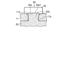
- FIG. 4 is a cross-sectional view showing a configuration in which a concave burr pocket 11d is provided on the outer peripheral edge of the through hole 11b of the housing 11.
- the burr pocket 11d is formed by cutting the outer peripheral edge portion of the through hole 11b into a rectangular shape so as to form a concave shape with the surface of the convex portion 22e inserted through the through hole 11b.
- FIG. 6 is a cross-sectional view showing a configuration in which a concave burr pocket 11e is provided on the outer peripheral edge of the through hole 11b of the housing 11.
- the burr pocket 11e is formed by cutting the outer peripheral edge portion of the through hole 11b into a curved convex shape.
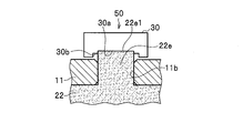
- FIG. 8 is a cross-sectional view showing a configuration in which a concave burr pocket 30b is provided on a button portion 30 set in a convex portion 22e of a ball sheet 22 protruding from a through hole 11b of a housing 11.
- the burr pocket 30b is formed by cutting the edge portion of the counterbore portion 30a of the button portion 30 into a rectangular shape so as to form a concave shape with the surface of the convex portion 22e set in the counterbore portion 30a.
- a counterbore cut into a slightly tapered shape is formed on the outer edge of the through hole 11b in order to facilitate the insertion of the convex portion 22e and prevent damage. This counterbore may not be present.
- the burr pocket 30b can be easily formed on the button portion 30, the burr pocket 30b can be provided at low cost.
- both the burr pocket 30b of the button portion 30 and the burr pocket 11c or 11d of the through hole 11b of the housing 11 described above may be provided in combination.
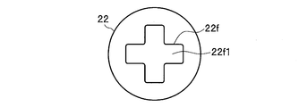
- FIG. 10 is a plan view of the ball sheet 22 when the convex portion 22f having a cross-shaped end surface 22f1 is viewed from the end surface side.
- the convex portion 22f has a cross-shaped columnar shape (cross columnar shape) in which the end surface 22f1 forms a cross shape.
- the through hole 11b of the housing 11 has a planar shape in which a cross columnar shape can be inserted without any gap.
- the cross-shaped convex portion 22f When the cross-shaped convex portion 22f is inserted into the cross-planar through hole 11b, both can be fixed without rotating like a circumference. Therefore, the ball sheet 22 can be fixed even if there is only one cross-shaped convex portion 22f.
- the diameter of the convex portion 22F and the cross-sectional area of the through hole 11b are set to a size that satisfies the required load of the pull-out load of the ball portion 10b.
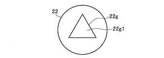
- FIG. 11 is a plan view of the ball sheet 22 when the convex portion 22g having a triangular end face 22g1 is viewed from the end face side.
- the convex portion 22g has a triangular columnar shape (triangular columnar shape) in which the end surface 22g1 forms a triangular shape.
- the through hole 11b of the housing 11 has a planar shape in which a triangular columnar shape can be inserted without any gap.
- the ball sheet 22 can be fixed even if there is only one triangular columnar convex portion 22g.
- the diameter of the convex portion 22F and the cross-sectional area of the through hole 11b are set to a size that satisfies the required load of the pull-out load of the ball portion 10b.
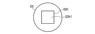
- ⁇ Shape examples 3 and 4 of the convex part of the ball sheet> Similar to the above-mentioned polygonal triangular columnar convex portion 22g, the square columnar convex portion 22h (shape example 3) in which the end surface 22h1 shown in FIG. 12 has a rectangular shape and the end surface 22i1 shown in FIG. 13 have a hexagonal shape.
- the hexagonal columnar convex portion 22i (shape example 3) may be formed.
- the inner surface shape of the through hole 11b is a quadrangular shape or a hexagonal columnar shape in the same manner as described above.
- the end face shape of the convex portion 22 of the ball sheet 22 may be a shape other than a circle (specific shape), and may be a through hole 11b having an inner plane shape similar to this. Even in this shape, the convex portion 22 inserted through the through hole 11b can be fixed without rotating, so that the ball sheet 22 can be firmly fixed to the housing 11.
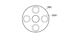
- FIG. 14 is a plan view showing the configuration of the button portion 30A of the shape example 1.
- the button portion 30A has a ring shape in which a plurality of (four in this example) convex portions 22e protruding from the ball sheet 22 can all come into contact with each other.
- the ring-shaped button portion 30A is formed with counterbore portions 30A1 at four positions corresponding to the four convex portions 22e of the ball sheet 22.
- the counterbore portion 30A1 may be formed with a circumferential recess in which the resin welded during laser welding escapes.
- each counterbore portion 30A1 is marked with a laser-transmissible mark so that the counterbore position can be known at the time of laser welding. If the button portion 30A is translucent and the convex portion 22e of the ball sheet 22 is brought into contact with each counterbore portion 30A1 and the convex portion 22e can be seen through, the above mark is unnecessary.
- the four counterbore portions 30A1 of the button portion 30A are set together with the four convex portions 22e protruding from the ball sheet 22. After that, while pressurizing the button portion 30A from above, the laser beam 50 is emitted to the position of the counterbore portion 30A1 of the button portion 30A.
- the four counterbore portions 30A1 of the button portion 30A may be set together with the four convex portions 22e. Therefore, as described above, the four button portions 30 are individually set on the four convex portions 22e. It can be set easily in a short time compared to the case. Therefore, the laser welding time including the set of the button portion 30A can be shortened. Further, if a laser device capable of emitting laser light to four counterbore portions 30A1 at the same time is used, the laser welding time can be further shortened.
- the shapes of the button portions 30 that can be set on the four convex portions 22e at one time include shape examples 2 to 5 shown in FIGS. 15 to 18 described later.
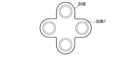
- FIG. 15 is a plan view showing the configuration of the button portion 30B of the shape example 2.
- the button portion 30B has a cross shape in which all four convex portions 22e can come into contact with each other, and a counterbore portion 30B1 is formed at a position corresponding to each convex portion 22e of the cross shape.
- FIG. 16 is a plan view showing the configuration of the button portion 30C of the shape example 3.
- the button portion 30C has a cross-shaped tip with a circular tip to which all four convex portions 22e of the ball sheet 22 can abut, and four circles corresponding to each convex portion 22e of the cross-shaped shape.
- a counterbore portion 30C1 is formed at the position of the shape.
- FIG. 17 is a plan view showing the configuration of the button portion 30D of the shape example 4.
- the button portion 30D has a quadrangular shape in which all four convex portions 22e can come into contact with each other, and a counterbore portion 30D1 is formed at a position corresponding to each of the quadrangular convex portions 22e.
- FIG. 18 is a plan view showing the configuration of the button portion 30E of the shape example 5.
- the button portion 30E has a circular shape in which all four convex portions 22e can come into contact with each other, and a counterbore portion 30E1 is formed at a position corresponding to each convex portion 22e of the circular shape.
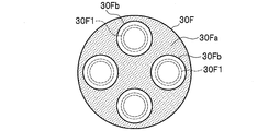
- FIG. 19 is a plan view showing the configuration of the two-color molded button portion 30F.
- the button portion 30F has a resin portion in which the large circular portion (first shape portion) 30 Fa to which the four convex portions 22e can abut is colored for identification, and a transparent resin at a position corresponding to the four convex portions 22e.
- a small circular portion (second shape portion) 30Fb is disposed of.
- the two-color molded button portion 30F having such a configuration, the following effect is obtained when the ball sheet 22 is distinguished from other parts as a specific color in the ball joint J. That is, it can be easily identified as a finished product by color as in the conventional case without lowering the transmittance of the resin of the small circular portion 30Fb which is the laser transmitting portion.
- a small circular portion 30F made of a transparent resin is arranged on the large circular portion 30F of the button portion 30F, and the convex portion 22e is in contact with the position of the small circular portion 30Fb, so that the laser beam 50 is projected.
- the portion 22e can be easily irradiated.
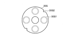
- FIG. 20 is a plan view showing the configuration of the button portion 30G with positioning.
- the button portion 30G has a circular shape in which all four convex portions 22e can come into contact with each other, and a counterbore portion 30G1 is formed at a position corresponding to each convex portion 22e of the circular shape, and is formed on the outer circumference of the circular shape.
- a plurality of V notches 30G2 (two in this example) formed by making a V-shaped notch are provided.
- a V-shaped convex portion (engagement convex portion) (not shown) in which the two V notches 30G2 are engaged is provided on the outer surface of the bottom portion of the housing 11 with a jig.
- the four counterbore portions 30G1 are set in contact with the convex portion 22e protruding from the through hole 11b at the bottom of the housing 11. It is provided at the outer surface of the housing.
- the two V notches 30G2 of the button portion 30G are only engaged with the V-shaped convex portion on the outer surface of the bottom of the housing 11 at the time of laser welding, so that the button portion 30G can be easily facilitated. Can be set in the housing 11.
- the ball joint J1 having a ball seat fixing structure of the present invention can be applied to a joint portion of a robot arm such as an industrial robot or a humanoid robot, or a device in which an arm such as an excavator car or a crane car rotates at the joint portion.
Landscapes
- Engineering & Computer Science (AREA)
- General Engineering & Computer Science (AREA)
- Mechanical Engineering (AREA)
- Pivots And Pivotal Connections (AREA)
Abstract
ボールジョイント(J1)のボールシート固定構造は、サスペンション又はスタビライザに一端部が連結されるスタッド部(10s)の他端部に、ボール部(10b)が一体に接合されて成るボールスタッド(10)と、開口から突き出るボールスタッド(10)のボール部(10b)を揺動及び回転可能に支持し、当該開口の反対側に貫通孔(11b)が設けられたハウジング(11)とを備える。ハウジング(11)内でボール部(10b)を包含し、貫通孔(11b)に挿通されて外部へ突き出る凸部(22e)を有するボールシート(22)を備える。この構成にて、ハウジング(11)の貫通孔(11b)に挿通されて外部へ突き出たボールシート(22)の凸部(22e)の端面(22e1)に、貫通孔(11b)よりも大きい樹脂製のボタン部(30)をレーザ溶着する構成とした。
Description
本発明は、車両の路面からの衝撃軽減等の役割を果たすサスペンションにおけるボールジョイントのボールシート固定構造及びボールシート固定方法に関する。
車両のサスペンションは、路面から車体に伝わる衝撃を軽減し、スタビライザは、車体のロール剛性(捩れに対する剛性)を高める。このサスペンションとスタビライザは、スタビリンクを介して連結されている。スタビリンクは、棒状のサポートバーの両端にボールジョイントを備えて構成されている。
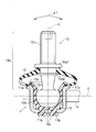
図21に示すように、ボールジョイントJとして、金属製のカップ状のハウジング11内に、樹脂製のボールシート12を介して金属製のボールスタッド10のボール部10bを回転自在に収容(包含)した構成がある。
ボールスタッド10は、棒状のスタッド部10sの一端に球状のボール部10bが一体に連結された構造となっている。スタッド部10sには、雄ねじ10nが螺刻されており、この雄ねじ10nよりも先端側(ボール部10b側)に、周回状に拡がる鍔部10a1と小鍔部10a2とが離間して形成されている。鍔部10a1とハウジング11の上端部との間には、ダストカバー13が配設されている。ダストカバー13は、ボールシート12の外側に湾曲状に折り曲げられた上端部12bと、ハウジング11の外側にL字状に折り曲げられた上端部11aとによって、挟持固定されている。
ハウジング11の外周面には、金属製のサポートバー1aが固定されている。サポートバー1aを水平線Hに沿って水平とした際に、ボールスタッド10の軸芯が水平線Hに対して垂直線Vで示す垂直となるように構成されている。
ボールシート12の上端部は、平坦面から内周側に傾斜するテーパ面12cを有する形状となっている。テーパ面12cの傾斜角は、ボールスタッド10が揺動(矢印α1)した際に、ボールスタッド10の予め定められた揺動角を満たす角度となっている。
ハウジング11の内面は、断面形状の縦壁がストレート形状となっており、この内面にボールシート12が収容されている。ボールシート12の内面は、ボール部10bの球状に沿った球形湾曲面12aの形状となっている。球形湾曲面12aをボールシート内球面12a又は内球面12aともいう。
ハウジング11の底部には、複数の貫通孔11bが形成されており、各貫通孔11bにボールシート12の底に設けられた凸部12aが挿通され、この挿通部分がハウジング11の外側に突き出て固定されている。この凸部12aの突き出た部分は、加熱溶融によりハウジング11の外面で拡幅後に冷却されて、貫通孔11bの径よりも大きいサイズの径と成されている。これによって、ボールシート12がハウジング11に固定されている。このような構成のボールジョイントとして、例えば特許文献1~3に記載のものがある。
上述したように、ボールシート12の凸部12aは、ハウジング11の貫通孔11bから外側に突き出た部分が、加熱溶融による拡幅後に冷却されて固定されている。しかし、ハウジング11の外面に突き出た凸部12aの拡幅部分は、カシメによる折れ込みが生じるために、固定強度が弱くなるという問題があった。
また、ハウジング11の貫通孔11bから外側に突き出た凸部12aの部分を加熱する際に、凸部12aの奥まで輻射熱で加熱する必要があるので、加熱時間が長くなる。このため、ボールシート12をハウジング11に固定する際のタクトタイムが長くなり、この結果、ボールジョイントJの製造コストが高くなるという問題があった。
本発明は、このような背景に鑑みてなされたものであり、ハウジング内でボール部を締め付けるボールシートを高強度で固定できると共に、その固定を短いタクトタイムで可能として製造コストを下げることができるボールジョイントのボールシート固定構造及びボールシート固定方法を提供することを課題とする。
前記した課題を解決するため、本発明のボールジョイントのボールシート固定構造は、構造体に一端部が連結されるスタッド部の他端部に、球体部が一体に接合されて成るボールスタッドと、当該ボールスタッドの球体部を揺動及び回転可能に支持し、当該ボールスタッドが開口から突出る空間を有し、当該開口の反対側に貫通孔が設けられたハウジングと、当該ハウジングと前記球体部との間に介在され、当該貫通孔に挿通されてハウジング外部へ突き出る凸部を有する樹脂製のボールシートとを備え、当該ボールシートに覆われた前記球体部が前記ハウジングで包含されるボールジョイントのボールシート固定構造であって、前記貫通孔に挿通されてハウジング外部へ突き出た前記ボールシートの凸部の端面に固定される、当該貫通孔よりも大きい樹脂製のボタン部を備え、前記ボタン部は、前記凸部の端面にレーザ溶着で固定されることを特徴とする。
本発明のボールシート固定方法は、構造体に一端部が連結されるスタッド部の他端部に、球体部が一体に接合されて成るボールスタッドと、当該ボールスタッドの球体部を揺動及び回転可能に支持し、当該ボールスタッドが開口から突出る空間を有し、当該開口の反対側に貫通孔が設けられたハウジングと、当該ハウジングと前記球体部との間に介在され、当該貫通孔に挿通されてハウジング外部へ突き出る凸部を有する樹脂製のボールシートとを備え、当該ボールシートに覆われた前記球体部が前記ハウジングで包含されるボールジョイントのボールシート固定方法であって、前記ボールジョイントは、前記貫通孔に挿通されてハウジング外部へ突き出た前記ボールシートの凸部の端面に固定される、当該貫通孔よりも大きいレーザ透過性樹脂によるボタン部を備え、前記凸部の端面に、前記ボタン部を当接してセットするステップと、レーザ光を前記ボタン部を透過して前記凸部の端面に照射するステップとを実行することを特徴とする。
本発明によれば、ハウジング内でボール部を締め付けるボールシートを高強度で固定できると共に、その固定を短いタクトタイムで可能として製造コストを下げることができる。
以下、本発明の実施形態を、図面を参照して説明する。
<実施形態>
図1は、本発明に係る実施形態のボールジョイントの縦断面図である。図1において図21に示した構成要素と同一部分には同一符号を付し、その説明を適宜省略する。
<実施形態>
図1は、本発明に係る実施形態のボールジョイントの縦断面図である。図1において図21に示した構成要素と同一部分には同一符号を付し、その説明を適宜省略する。
図1に示す本実施形態のボールジョイントJ1が、従来のボールジョイントJ(図21)と異なる点は、ハウジング11の底部の各貫通孔11bに挿通されて突き出た樹脂製のボールシート22における凸部22eの端面に、貫通孔11bよりも大きな樹脂製のボタン部30をレーザ溶着したことにある。但し、凸部22eの突出部は円柱形状で、貫通孔11bの内面は、その円柱形状が略隙間なく挿通可能な、円周形状であるとする。
ボタン部30はハウジング11の外面からレーザ溶着され、貫通孔11bより大きいサイズなので、ボタン部30とボールシート22Aとがハウジング11を挟んで3者が共に固定状態となっている。このため、ボールシート22がハウジング11に固定されている。レーザ溶着は、ボタン部30に矢印で示すレーザ光50を出射するダイオードレーザ装置等のレーザ装置(図示せず)を用いて行う。
ボールシート22の上端部22bは、平坦面から内周側に傾斜するテーパ面22cを有する形状となっている。テーパ面22cの傾斜角は、ボールスタッド10が揺動(矢印α1)した際に、ボールスタッド10の予め定められた揺動角を満たす角度となっている。ハウジング11に収容されたボールシート22の内面は、ボール部10bの球状に沿った球形湾曲面22aの形状となっている。球形湾曲面22aを内球面22aともいう。
ハウジング11は、鉄板等の金属板がプレス成形又は冷鍛によってカップ形状に成形されている。このカップ形状の開口端部11aが外側に断面L字状に折り曲げられた上端部11aを有する薄鍔タイプとなっている。ダストカバー13は上端部が、ボールスタッド10の鍔部10a1に固定され、下端部が、ハウジング11の上端部11aと、ボールシート22の外側に湾曲状に折り曲げられた上端部22bとの間に挟持固定されている。
また、ボールジョイントJ1のスタッド部10sは、図示せぬサスペンション又はスタビライザに固定されている。サスペンション又はスタビライザは、請求項記載の構造体を構成する。
図2はハウジング11の貫通孔11bに挿通されたボールシート22の凸部22eの端面22e1に、ボタン部30を載置した構成を示す断面図である。この図2の構成は図1に示すボールジョイントJ1を逆さまにした状態であり、通常、この状態で、後述のようにボタン部30を凸部22eへレーザ溶着する。
ボタン部30は、円盤形状で、矢印で示すレーザ光50を20%以上透過する色の樹脂(透過性樹脂という)により形成されている。これに対して、ボールシート22は、レーザ光50を透過しない又はレーザ光50を20%未満透過する色の樹脂(非透過性樹脂という)により形成されている。
ボタン部30の凸部22eが溶着される面には、凸部22eの端面22e1が嵌るザグリ部30aが形成されている。ボタン部30の厚さは、レーザ光50の透過率に応じて決定し、1mm~10mmとするのが好ましい。例えば、ボタン部30の厚さは、2.7mm等とするのが好ましく、ザグリ部30aを考慮したレーザ光50の透過厚は、最大2mmとするのが好ましい。また、凸部22eを含むボールシート22の材料は、ポリアセタール(polyacetal)又はポリオキシメチレン(polyoxymethylene)であるPOMが好ましい。
凸部22eは、ハウジング11の貫通孔11bに挿通した際に、端面22e1がハウジング11の外面から僅かに突き出る長さとなっている。この凸部22eの長さは、ハウジング11の板厚+所定長さ(例えば1.0mm、又は0.5mm~5mm)とする。凸部22eの端面は、フラットであることが好ましい。また、貫通孔11bに凸部22eを挿通した際に、この双方の間に0.01mm~1mmのギャップを有するように、貫通孔11bの径を定めるのが好ましい。
ハウジング11の貫通孔11bには、貫通孔11bの外側縁部をテーパ形状に削ったバリポケット11cが形成されている。バリポケット11cは、レーザ溶接の際に、凸部22eやボタン部30の溶融に伴って出るバリを、逃がして収容するためのものである。なお、貫通孔11bの内側縁部には、凸部22eを入れ易くしたり、破損を防止したりするために、僅かにテーパ形状に削ったザグリが形成されている。
ハウジング11の底部の複数(本例では4つ)の貫通孔11bの総断面積は、ボール部10bの抜け荷重(スタッド抜け荷重)の要求荷重に応じて定まる。また、ボールシート22の凸部22eの径も、同じ要求荷重に応じて定まるようになっている。
<レーザ溶着の動作>
図2に示す構成のボールシート22の凸部22eにザグリ部30aを介して載置されたボタン部30を、所定の圧力で上方から加圧しながら、レーザ光50をボタン部30に向けて出射する。この出射されたレーザ光50は、透過性樹脂のボタン部30を透過して凸部22eの端面22e1に照射される。凸部22eは非透過性樹脂であって、レーザ光50を透過しないので発熱し、この発熱で端面22e1が溶融する。この際、端面22e1と加圧されて当接するボタン部30のザグリ部30aも、端面22e1からの発熱が伝導して、ある深さ溶融する。
図2に示す構成のボールシート22の凸部22eにザグリ部30aを介して載置されたボタン部30を、所定の圧力で上方から加圧しながら、レーザ光50をボタン部30に向けて出射する。この出射されたレーザ光50は、透過性樹脂のボタン部30を透過して凸部22eの端面22e1に照射される。凸部22eは非透過性樹脂であって、レーザ光50を透過しないので発熱し、この発熱で端面22e1が溶融する。この際、端面22e1と加圧されて当接するボタン部30のザグリ部30aも、端面22e1からの発熱が伝導して、ある深さ溶融する。
このような溶融によって、図3に示すように、凸部22e及びボタン部30の溶融樹脂がハウジング11のバリポケット11cに満遍なく流れ込むと共に、凸部22eとボタン部30との界面の溶融樹脂が混合する。この界面の溶融により、ハウジング11、ボールシート22の凸部22e及びボタン部30の密着性が高まり、この状態で全体が冷却されると、ハウジング11、ボールシート22の凸部22e及びボタン部30が溶着(又は接合)する。
<実施形態の効果>
このような本実施形態のボールジョイントのボールシート固定構造の効果について説明する。ボールジョイントJ1は、構造体としてのサスペンション又はスタビライザに一端部が連結されるスタッド部10sの他端部に、金属製のボール部10bが一体に接合されて成るボールスタッド10と、ボールスタッド10のボール部10bを揺動及び回転可能に支持し、ボールスタッド10が開口から突出る空間を有し、当該開口の反対側に貫通孔11bが設けられた金属製のハウジング11とを備える。更に、ハウジング11とボール部10bとの間に介在され、貫通孔11bに挿通されてハウジング11外部へ突き出る凸部22eを有する樹脂製のボールシート22とを備える。そして、ボールシート22に覆われたボール部10bがハウジング11で包含されて成る。このようなボールジョイントJ1のボールシート固定構造を次の特徴構成とした。
このような本実施形態のボールジョイントのボールシート固定構造の効果について説明する。ボールジョイントJ1は、構造体としてのサスペンション又はスタビライザに一端部が連結されるスタッド部10sの他端部に、金属製のボール部10bが一体に接合されて成るボールスタッド10と、ボールスタッド10のボール部10bを揺動及び回転可能に支持し、ボールスタッド10が開口から突出る空間を有し、当該開口の反対側に貫通孔11bが設けられた金属製のハウジング11とを備える。更に、ハウジング11とボール部10bとの間に介在され、貫通孔11bに挿通されてハウジング11外部へ突き出る凸部22eを有する樹脂製のボールシート22とを備える。そして、ボールシート22に覆われたボール部10bがハウジング11で包含されて成る。このようなボールジョイントJ1のボールシート固定構造を次の特徴構成とした。
(1)ボールジョイントJ1のボールシート固定構造は、貫通孔11bに挿通されてハウジング11外部へ突き出たボールシート22の凸部22eの端面22e1に固定される、当該貫通孔11bよりも大きい樹脂製のボタン部30を備える。ボタン部30が、凸部22eの端面22e1にレーザ溶着で固定される構成とした。
この構成によれば、ハウジング11の貫通孔11bに挿通されて外部へ突き出たボールシート22の凸部に、貫通孔11bより大きいボタン部30がレーザ溶着される。これにより、ボタン部30とボールシート22とがハウジング11を挟んで3者が共に固定状態となるため、ボールシート22がハウジング11に固定される。このようにレーザ溶着でボールシート22をハウジング11に固定することができるので、従来のボールシート22の凸部をヒータ等で加熱して固定する処理よりも、レーザ光50による発熱の方が溶着度が高くなり、溶着時間が短く、固定工程のタクトタイムが短くなる。つまり、ハウジング11内でボール部10bを締め付けるボールシート22を高強度で固定できると共に、その固定を短いタクトタイムで可能として製造コストを下げることができる。
また、レーザ溶着によれば、凸部22e及びボタン部30の溶融樹脂がハウジング11のバリポケット11cに満遍なく流れ込み、凸部22eとボタン部30との界面の溶融樹脂が混合し、溶融して冷却される際に、成形収縮と熱収縮により上記3者の密着性が高まる。このため、ボタン部30とハウジング11との間に隙間が出来ないので、泥水等の浸入を防ぐことができる。また、隙間が出来ないので、ハウジング11とボールシート22間のガタを防止できる。
なお、ボタン部30を上方から加圧しながらボールシート22の凸部22eにレーザ溶着することにより、上記3者の密着性を高めて隙間なく溶着できる。
上述したように3者を密着性を高めて隙間なく溶着すると、溶着が強固になるので、後述の弾性リフト量を所定値に保証することが可能となる。つまり、ハウジング11内のボール部10bに対するボールシート22の締め代を、適正な弾性リフト量となる状態に保持し、この保持状態で上記レーザ溶着を行えばよい。
なお、弾性リフト量とは、ハウジング11内のボールシート22を介したボール部10bの移動量である。弾性リフト量が大きくなると、ボールジョイントJ1にガタが発生し、車両走行中の異音の発生に繋がる。
(2)ボタン部30は、レーザ光を20%以上透過する透過性樹脂により形成され、ボールシート22は、レーザ光50を透過しない非透過性樹脂により形成されている構成とした。
この構成によれば、ボールシート22の凸部22eの端面22e1にセットされたボタン部30に向けてレーザ光50を出射すると、レーザ光50は、透過性樹脂のボタン部30を透過して非透過性樹脂のボールシート22の凸部22eの端面22e1に照射される。凸部22eはレーザ光を透過しないので発熱し、この発熱で端面22e1が溶融する。この際、凸部22eの端面22e1と当接するボタン部30の面も、凸部22eの端面22e1からの発熱が伝導して溶融する。この界面の溶融後に冷却により、ボールシート22の凸部22eとボタン部30を溶着できる。
(3)ハウジング11における貫通孔11bの内周面の外側縁部に、当該外側縁部をテーパ状に削り取って形成したバリポケット11cを設ける構成とした。
この構成によれば、ハウジング11の貫通孔11bのバリポケット11cに、レーザ溶接の際にボールシート22の凸部22eやボタン部30の溶融時に出るバリを逃がして収容できる。このため、上記3者を隙間なく溶着できる。
<バリポケット変形例1>
図4はハウジング11の貫通孔11bの外周縁部に凹状のバリポケット11dを設けた構成を示す断面図である。バリポケット11dは、貫通孔11bの外周縁部を矩形状に切削し、貫通孔11bに挿通された凸部22eの面との間で凹状となるように形成されている。
図4はハウジング11の貫通孔11bの外周縁部に凹状のバリポケット11dを設けた構成を示す断面図である。バリポケット11dは、貫通孔11bの外周縁部を矩形状に切削し、貫通孔11bに挿通された凸部22eの面との間で凹状となるように形成されている。
ボタン部30の上方からレーザ光50を出射して凸部22eの端面22e1を発熱すると、図5に示すように、端面22e1及びボタン部30のザグリ部30aが溶融する。この溶融樹脂に係るバリがバリポケット11dに収容されるので、上記3者を隙間なく溶着できる。
<バリポケット変形例2>
図6はハウジング11の貫通孔11bの外周縁部に凹状のバリポケット11eを設けた構成を示す断面図である。バリポケット11eは、貫通孔11bの外周縁部を湾曲凸状に切削して形成されている。
図6はハウジング11の貫通孔11bの外周縁部に凹状のバリポケット11eを設けた構成を示す断面図である。バリポケット11eは、貫通孔11bの外周縁部を湾曲凸状に切削して形成されている。
ボタン部30の上方からレーザ光50を出射して凸部22eの端面22e1を発熱すると、図7に示すように、凸部22eの端面22e1及びボタン部30のザグリ部30aが溶融する。この溶融樹脂に係るバリがバリポケット11eに収容されるので、上記3者を隙間なく溶着できる。
<バリポケット変形例3>
図8はハウジング11の貫通孔11bから突き出たボールシート22の凸部22eにセットされるボタン部30に凹状のバリポケット30bを設けた構成を示す断面図である。バリポケット30bは、ボタン部30のザグリ部30aの縁部を矩形状に切削し、ザグリ部30aにセットされた凸部22eの面との間で凹状となるように形成されている。
図8はハウジング11の貫通孔11bから突き出たボールシート22の凸部22eにセットされるボタン部30に凹状のバリポケット30bを設けた構成を示す断面図である。バリポケット30bは、ボタン部30のザグリ部30aの縁部を矩形状に切削し、ザグリ部30aにセットされた凸部22eの面との間で凹状となるように形成されている。
なお、貫通孔11bの外側縁部には、凸部22eを入れ易くしたり、破損を防止したりするために、僅かにテーパ形状に削ったザグリが形成されている。このザグリは無くてもよい。
ボタン部30の上方からレーザ光50を出射して凸部22eの端面22e1を発熱すると、図9に示すように、凸部22eの端面22e1及びボタン部30のザグリ部30aが溶融する。この溶融樹脂に係るバリがバリポケット30bに収容されるので、上記3者を隙間なく溶着できる。また、ボタン部30にはバリポケット30bを容易に形成できるので、バリポケット30bを低コストで設けることができる。
但し、ボタン部30のバリポケット30bと、上述したハウジング11の貫通孔11bの部分のバリポケット11c又は11dとの双方を組み合わせて設けてもよい。
<ボールシートの凸部の形状例1>
図10はボールシート22において、端面22f1が十字形状の凸部22fを端面側から見た平面図である。
この凸部22fは、端面22f1が十字形状を成す十字形状の柱状(十字柱状)となっている。この凸部22fの場合、ハウジング11の貫通孔11bは、この平面形状が、十字柱状が略隙間なく挿通可能な十字形状となっている。
図10はボールシート22において、端面22f1が十字形状の凸部22fを端面側から見た平面図である。
この凸部22fは、端面22f1が十字形状を成す十字形状の柱状(十字柱状)となっている。この凸部22fの場合、ハウジング11の貫通孔11bは、この平面形状が、十字柱状が略隙間なく挿通可能な十字形状となっている。
十字柱状の凸部22fを、十字平面形状の貫通孔11bに挿通した状態では、双方が円周状のように回動せず固定状態とできる。このため、十字柱状の凸部22fが1本でも、ボールシート22を固定できる。この場合、凸部22Fの径及び貫通孔11bの断面積が、ボール部10bの抜け荷重の要求荷重を満たすサイズとする。
<ボールシートの凸部の形状例2>
図11はボールシート22において、端面22g1が三角形状の凸部22gを端面側から見た平面図である。
この凸部22gは、端面22g1が三角形状を成す三角形状の柱状(三角柱状)となっている。この凸部22gの場合、ハウジング11の貫通孔11bは、この平面形状が、三角柱状が略隙間なく挿通可能な三角形状となっている。
図11はボールシート22において、端面22g1が三角形状の凸部22gを端面側から見た平面図である。
この凸部22gは、端面22g1が三角形状を成す三角形状の柱状(三角柱状)となっている。この凸部22gの場合、ハウジング11の貫通孔11bは、この平面形状が、三角柱状が略隙間なく挿通可能な三角形状となっている。
三角柱状の凸部22gを、三角平面形状の貫通孔11bに挿通した状態では、双方が回動せず固定状態とできる。このため、三角柱状の凸部22gが1本でも、ボールシート22を固定できる。この場合、凸部22Fの径及び貫通孔11bの断面積が、ボール部10bの抜け荷重の要求荷重を満たすサイズとする。
<ボールシートの凸部の形状例3,4>
上記の多角形状である三角柱状の凸部22gと同様に、図12に示す端面22h1が四角形状を成す四角柱状の凸部22h(形状例3)や、図13に示す端面22i1が六角形状を成す六角柱状の凸部22i(形状例3)としてもよい。これら凸部22h,22iの場合も、上記同様に、貫通孔11bの内面形状を四角形状や六角柱状とする。
上記の多角形状である三角柱状の凸部22gと同様に、図12に示す端面22h1が四角形状を成す四角柱状の凸部22h(形状例3)や、図13に示す端面22i1が六角形状を成す六角柱状の凸部22i(形状例3)としてもよい。これら凸部22h,22iの場合も、上記同様に、貫通孔11bの内面形状を四角形状や六角柱状とする。
従って、ボールシート22の凸部22の端面形状が円形以外の形状(特定形状)で、これと相似形の内面平面形状の貫通孔11bであってもよい。この形状の場合も、貫通孔11bに挿通した凸部22を回動せず固定状態とできるので、ボールシート22をハウジング11に強固に固定できる。
<ボタン部の形状例1>
図14は形状例1のボタン部30Aの構成を示す平面図である。
ボタン部30Aは、ボールシート22から突き出た複数本(本例では4本)の凸部22eが全て当接可能な環形状を成す。この環形状のボタン部30Aには、ボールシート22の4本の凸部22eに対応する4つの位置に、ザグリ部30A1が形成されている。このザグリ部30A1には、レーザ溶着時に溶着した樹脂が逃げる凹部が周回状に形成されていてもよい。
図14は形状例1のボタン部30Aの構成を示す平面図である。
ボタン部30Aは、ボールシート22から突き出た複数本(本例では4本)の凸部22eが全て当接可能な環形状を成す。この環形状のボタン部30Aには、ボールシート22の4本の凸部22eに対応する4つの位置に、ザグリ部30A1が形成されている。このザグリ部30A1には、レーザ溶着時に溶着した樹脂が逃げる凹部が周回状に形成されていてもよい。
各ザグリ部30A1の裏面位置には、レーザ溶着時にザグリ位置が分かるように、レーザ透過可能なマークを付けておく。ボタン部30Aが半透明で各ザグリ部30A1にボールシート22の凸部22eを当接した際に、凸部22eが透けて見えれば、上記マークは不要である。
レーザ溶着を行う場合、ボールシート22から突き出た4つの凸部22eに、ボタン部30Aの4つのザグリ部30A1を合わせてセットする。この後、ボタン部30Aを上方から加圧しながら、レーザ光50をボタン部30Aのザグリ部30A1の位置に出射する。
このように、4つの凸部22eに、ボタン部30Aの4つのザグリ部30A1を合わせてセットすれば良いので、前述したように、4つのボタン部30を4つの凸部22eに個別にセットする場合に比べ、短時間で容易にセットできる。このため、ボタン部30Aのセットを含めたレーザ溶着時間を短縮できる。また、レーザ光の出射を、4つのザグリ部30A1に同時に行うことが可能なレーザ装置を用いれば、レーザ溶着時間を更に短縮できる。
このような4つの凸部22eに、一度でセット可能なボタン部30の形状は、後述の図15~図18に示す形状例2~5がある。
<ボタン部の形状例2>
図15は形状例2のボタン部30Bの構成を示す平面図である。ボタン部30Bは、4本の凸部22eが全て当接可能な十字形状を成し、この十字形状の各凸部22eに対応する位置にザグリ部30B1が形成されている。
図15は形状例2のボタン部30Bの構成を示す平面図である。ボタン部30Bは、4本の凸部22eが全て当接可能な十字形状を成し、この十字形状の各凸部22eに対応する位置にザグリ部30B1が形成されている。
<ボタン部の形状例3>
図16は形状例3のボタン部30Cの構成を示す平面図である。ボタン部30Cは、ボールシート22の4本の凸部22eが全て当接可能な十字形の先端が円形の十字円形状を成し、この十字円形状の各凸部22eに対応する4つの円形状の位置にザグリ部30C1が形成されている。
図16は形状例3のボタン部30Cの構成を示す平面図である。ボタン部30Cは、ボールシート22の4本の凸部22eが全て当接可能な十字形の先端が円形の十字円形状を成し、この十字円形状の各凸部22eに対応する4つの円形状の位置にザグリ部30C1が形成されている。
<ボタン部の形状例4>
図17は形状例4のボタン部30Dの構成を示す平面図である。ボタン部30Dは、4本の凸部22eが全て当接可能な四角形状を成し、この四角形状の各凸部22eに対応する位置にザグリ部30D1が形成されている。
図17は形状例4のボタン部30Dの構成を示す平面図である。ボタン部30Dは、4本の凸部22eが全て当接可能な四角形状を成し、この四角形状の各凸部22eに対応する位置にザグリ部30D1が形成されている。
<ボタン部の形状例5>
図18は形状例5のボタン部30Eの構成を示す平面図である。ボタン部30Eは、4本の凸部22eが全て当接可能な円形状を成し、この円形状の各凸部22eに対応する位置にザグリ部30E1が形成されている。
図18は形状例5のボタン部30Eの構成を示す平面図である。ボタン部30Eは、4本の凸部22eが全て当接可能な円形状を成し、この円形状の各凸部22eに対応する位置にザグリ部30E1が形成されている。
<ボタン部の二色成型例>
図19は二色成型のボタン部30Fの構成を示す平面図である。ボタン部30Fは、4本の凸部22eが当接可能な大円形部(第1形状部)30Faを識別用に着色した樹脂部と、4つの凸部22eに対応する位置に、透過性樹脂による小円形部(第2形状部)30Fbを配設して構成されている。
図19は二色成型のボタン部30Fの構成を示す平面図である。ボタン部30Fは、4本の凸部22eが当接可能な大円形部(第1形状部)30Faを識別用に着色した樹脂部と、4つの凸部22eに対応する位置に、透過性樹脂による小円形部(第2形状部)30Fbを配設して構成されている。
このような構成の二色成型のボタン部30Fによれば、ボールジョイントJにおいて、ボールシート22を特定色として他部品と識別する場合に次の効果を奏する。即ち、レーザ透過部である小円形部30Fbの樹脂の透過率を下げることなく、従来のように色により完成品として容易に識別できる。
また、ボタン部30Fの大円形部30Faに、透過性樹脂による小円形部30Faが配設されており、この小円形部30Fbの位置に凸部22eが当接しているので、レーザ光50を凸部22eに容易に照射できる。
<位置決め付きボタン部>
図20は位置決め付きボタン部30Gの構成を示す平面図である。ボタン部30Gは、4本の凸部22eが全て当接可能な円形状を成し、この円形状の各凸部22eに対応する位置にザグリ部30G1が形成されており、円形状の外周にV字状に切込みを入れて形成したVノッチ30G2を複数(本例では2つ)設けてある。
図20は位置決め付きボタン部30Gの構成を示す平面図である。ボタン部30Gは、4本の凸部22eが全て当接可能な円形状を成し、この円形状の各凸部22eに対応する位置にザグリ部30G1が形成されており、円形状の外周にV字状に切込みを入れて形成したVノッチ30G2を複数(本例では2つ)設けてある。
但し、ハウジング11の底部の外面には、2つのVノッチ30G2が係合される図示せぬV字状凸部(係合凸部)を治具にて設ける。このV字状凸部は、ボタン部30GのVノッチ30G2を係合した際に、4つのザグリ部30G1が、ハウジング11の底部の貫通孔11bから突き出た凸部22eに当接してセットされるハウジング外面位置に設けてある。
このような位置決め付きボタン部30Gを用いれば、レーザ溶着時に、ボタン部30Gの2つのVノッチ30G2を、ハウジング11の底部外面のV字状凸部に係合させるだけなので、ボタン部30Gを容易にハウジング11にセットできる。
その他、具体的な構成について、本発明の主旨を逸脱しない範囲で適宜変更が可能である。
本発明のボールシート固定構造のボールジョイントJ1は、産業用ロボットや人型ロボット等のロボットアームの関節部分や、ショベルカーやクレーン車等のアームが関節部分で回転する装置に適用可能である。
本発明のボールシート固定構造のボールジョイントJ1は、産業用ロボットや人型ロボット等のロボットアームの関節部分や、ショベルカーやクレーン車等のアームが関節部分で回転する装置に適用可能である。
1a サポートバー
10 ボールスタッド
10b ボール部(球体部)
10s スタッド部
11 ハウジング
11a ハウジングの上端部
11b ハウジングの貫通孔
11c,11d,11e ハウジングのバリポケット
11g 凹凸
22 ボールシート
22e ボールシートの凸部
22e1 ボールシートの凸部の端面
22f 端面が十字形状のハウジング凸部
22f1 端面が十字形状のハウジング凸部の端面
22g 端面が三角形状のハウジング凸部
22g1 端面が三角形状のハウジング凸部の端面
22h 端面が四角形状のハウジング凸部
2hh1 端面が四角形状のハウジング凸部の端面
22i 端面が六角形状のハウジング凸部
22i1 端面が六角形状のハウジング凸部の端面
30 ボタン部
30a ボタン部のザグリ
30b ボタン部のバリポケット
30A 環形状のボタン部
30A1,30B1,30C1,30D1,30E1,30F1,30G1 ザグリ部
30B 十字形状のボタン部
30C 十字円形状のボタン部
30D 四角形状のボタン部
30E 円形状のボタン部
30F 二色成型のボタン部
30Fa 大円形部(第1形状部)
30Fb 小円形部(第2形状部)
30G 位置決め付きボタン部
30G2 Vノッチ
50 レーザ光
10 ボールスタッド
10b ボール部(球体部)
10s スタッド部
11 ハウジング
11a ハウジングの上端部
11b ハウジングの貫通孔
11c,11d,11e ハウジングのバリポケット
11g 凹凸
22 ボールシート
22e ボールシートの凸部
22e1 ボールシートの凸部の端面
22f 端面が十字形状のハウジング凸部
22f1 端面が十字形状のハウジング凸部の端面
22g 端面が三角形状のハウジング凸部
22g1 端面が三角形状のハウジング凸部の端面
22h 端面が四角形状のハウジング凸部
2hh1 端面が四角形状のハウジング凸部の端面
22i 端面が六角形状のハウジング凸部
22i1 端面が六角形状のハウジング凸部の端面
30 ボタン部
30a ボタン部のザグリ
30b ボタン部のバリポケット
30A 環形状のボタン部
30A1,30B1,30C1,30D1,30E1,30F1,30G1 ザグリ部
30B 十字形状のボタン部
30C 十字円形状のボタン部
30D 四角形状のボタン部
30E 円形状のボタン部
30F 二色成型のボタン部
30Fa 大円形部(第1形状部)
30Fb 小円形部(第2形状部)
30G 位置決め付きボタン部
30G2 Vノッチ
50 レーザ光
Claims (9)
- 構造体に一端部が連結されるスタッド部の他端部に、球体部が一体に接合されて成るボールスタッドと、当該ボールスタッドの球体部を揺動及び回転可能に支持し、当該ボールスタッドが開口から突出る空間を有し、当該開口の反対側に貫通孔が設けられたハウジングと、当該ハウジングと前記球体部との間に介在され、当該貫通孔に挿通されてハウジング外部へ突き出る凸部を有する樹脂製のボールシートとを備え、当該ボールシートに覆われた前記球体部が前記ハウジングで包含されるボールジョイントのボールシート固定構造であって、
前記貫通孔に挿通されてハウジング外部へ突き出た前記ボールシートの凸部の端面に固定される、当該貫通孔よりも大きい樹脂製のボタン部を備え、
前記ボタン部は、前記凸部の端面にレーザ溶着で固定される
ことを特徴とするボールジョイントのボールシート固定構造。 - 前記ボタン部は、レーザ光を20%以上透過する透過性樹脂により形成され、前記ボールシートは、レーザ光を透過しない又はレーザ光を20%未満透過する非透過性樹脂により形成されている
ことを特徴とする請求項1に記載のボールジョイントのボールシート固定構造。 - 前記ハウジングにおける貫通孔の内周面の外側縁部に、当該外側縁部を削り取る又は凹ませて形成したバリポケットを設ける
ことを特徴とする請求項1又は2に記載のボールジョイントのボールシート固定構造。 - 前記ボタン部における前記ボールシートの凸部と当接する面の縁部に、凹状のバリポケットを設ける
ことを特徴とする請求項1~3の何れか1項に記載のボールジョイントのボールシート固定構造。 - 前記ボールシートの凸部は、当該凸部の端面形状が円形以外の特定形状で、前記貫通孔の平面形状が、前記特定形状の凸部が挿通可能な形状である
ことを特徴とする請求項1~4の何れか1項に記載のボールジョイントのボールシート固定構造。 - 前記ボタン部は、前記ボールシートの凸部が複数設けられている場合に、複数の凸部が全て当接可能な形状を成す
ことを特徴とする請求項1~5の何れか1項に記載のボールジョイントのボールシート固定構造。 - 前記ボタン部は、前記凸部が当接可能な非透過性樹脂による第1形状部を識別用に着色した樹脂部と、当該第1形状部の前記凸部に対応する位置に配設された透過性樹脂による第2形状部とを備えて成る
ことを特徴とする請求項1又は2に記載のボールジョイントのボールシート固定構造。 - 前記ボタン部は、当該ボタン部の外周縁に切込みを入れて形成したノッチを複数設け、
前記ハウジングの貫通孔から突き出た凸部が前記ボタン部の片面に当接されるように、前記ノッチが個別に係合可能な複数の係合凸部を治具にて設けた
ことを特徴とする請求項1~7の何れか1項に記載のボールジョイントのボールシート固定構造。 - 構造体に一端部が連結されるスタッド部の他端部に、球体部が一体に接合されて成るボールスタッドと、当該ボールスタッドの球体部を揺動及び回転可能に支持し、当該ボールスタッドが開口から突出る空間を有し、当該開口の反対側に貫通孔が設けられたハウジングと、当該ハウジングと前記球体部との間に介在され、当該貫通孔に挿通されてハウジング外部へ突き出る凸部を有する樹脂製のボールシートとを備え、当該ボールシートに覆われた前記球体部が前記ハウジングで包含されるボールジョイントのボールシート固定方法であって、
前記ボールジョイントは、
前記貫通孔に挿通されてハウジング外部へ突き出た前記ボールシートの凸部の端面に固定される、当該貫通孔よりも大きいレーザ透過性樹脂によるボタン部を備え、
前記凸部の端面に、前記ボタン部を当接してセットするステップと、
レーザ光を前記ボタン部を透過して前記凸部の端面に照射するステップと
を実行することを特徴とするボールシート固定方法。
Applications Claiming Priority (2)
| Application Number | Priority Date | Filing Date | Title |
|---|---|---|---|
| JP2019076617A JP7181149B2 (ja) | 2019-04-12 | 2019-04-12 | ボールジョイントのボールシート固定構造及びボールシート固定方法 |
| JP2019-076617 | 2019-04-12 |
Publications (1)
| Publication Number | Publication Date |
|---|---|
| WO2020209090A1 true WO2020209090A1 (ja) | 2020-10-15 |
Family
ID=72751609
Family Applications (1)
| Application Number | Title | Priority Date | Filing Date |
|---|---|---|---|
| PCT/JP2020/013803 Ceased WO2020209090A1 (ja) | 2019-04-12 | 2020-03-26 | ボールジョイントのボールシート固定構造及びボールシート固定方法 |
Country Status (2)
| Country | Link |
|---|---|
| JP (1) | JP7181149B2 (ja) |
| WO (1) | WO2020209090A1 (ja) |
Citations (3)
| Publication number | Priority date | Publication date | Assignee | Title |
|---|---|---|---|---|
| JP2015152153A (ja) * | 2014-02-18 | 2015-08-24 | 日本発條株式会社 | リンクアーム部材 |
| JP2017096501A (ja) * | 2016-12-21 | 2017-06-01 | アイシン機工株式会社 | 壁体固着部構造及び車両部品の製造方法 |
| JP3217755U (ja) * | 2018-02-12 | 2018-08-30 | 廖福山LIAO, Fu−Shan | スタビライザーボールジョイント構造 |
-
2019
- 2019-04-12 JP JP2019076617A patent/JP7181149B2/ja active Active
-
2020
- 2020-03-26 WO PCT/JP2020/013803 patent/WO2020209090A1/ja not_active Ceased
Patent Citations (3)
| Publication number | Priority date | Publication date | Assignee | Title |
|---|---|---|---|---|
| JP2015152153A (ja) * | 2014-02-18 | 2015-08-24 | 日本発條株式会社 | リンクアーム部材 |
| JP2017096501A (ja) * | 2016-12-21 | 2017-06-01 | アイシン機工株式会社 | 壁体固着部構造及び車両部品の製造方法 |
| JP3217755U (ja) * | 2018-02-12 | 2018-08-30 | 廖福山LIAO, Fu−Shan | スタビライザーボールジョイント構造 |
Also Published As
| Publication number | Publication date |
|---|---|
| JP2020173012A (ja) | 2020-10-22 |
| JP7181149B2 (ja) | 2022-11-30 |
Similar Documents
| Publication | Publication Date | Title |
|---|---|---|
| JP6204994B2 (ja) | 流体継手の製造方法及び流体継手 | |
| EP1486314B8 (en) | Laser-welded assembly and method for producing it | |
| WO2011089706A1 (ja) | 溶接構造および溶接方法 | |
| JPWO2011033979A1 (ja) | 発光装置 | |
| JP5172183B2 (ja) | 等速自在継手の外側継手部材 | |
| WO2020209090A1 (ja) | ボールジョイントのボールシート固定構造及びボールシート固定方法 | |
| JP2010207850A (ja) | 溶接接合部材及び溶接接合方法 | |
| KR101707913B1 (ko) | 디퍼렌셜 조립체를 위한 웰드 | |
| CN110678291B (zh) | 用于制造车轴轴身的方法以及车轴轴身 | |
| JP2006281599A (ja) | 接合体および接合方法 | |
| WO2012101872A1 (ja) | ペダルアームの軸受部材、およびペダルアーム | |
| JP2005153162A (ja) | レーザ溶着方法、構造およびスロットルバルブ装置 | |
| ES2696925T3 (es) | Procedimiento de fabricación de una bola de juego | |
| JP2004076901A (ja) | ハードディスクドライブ用ピボットアッセンブリ | |
| JP5300631B2 (ja) | 樹脂製容器 | |
| CN211305373U (zh) | 一种钣金件焊接的精密定位装置 | |
| JP4301412B2 (ja) | 弾性軸継手の製造方法及びその弾性軸継手 | |
| KR100382858B1 (ko) | 용접 구조 | |
| JP5835143B2 (ja) | 樹脂ケースの製造方法 | |
| CN101131190A (zh) | 缸体装置及其制造方法 | |
| JPH11303711A (ja) | 燃料噴射ノズル | |
| JP2003013751A (ja) | スロットルバルブ装置とその製造方法 | |
| WO2020085138A1 (ja) | ボールジョイントのボールシート固定構造 | |
| WO2013175825A1 (ja) | スポット溶接ガンのティーチング用チップ | |
| JP2005297225A5 (ja) |
Legal Events
| Date | Code | Title | Description |
|---|---|---|---|
| 121 | Ep: the epo has been informed by wipo that ep was designated in this application |
Ref document number: 20788481 Country of ref document: EP Kind code of ref document: A1 |
|
| NENP | Non-entry into the national phase |
Ref country code: DE |
|
| 122 | Ep: pct application non-entry in european phase |
Ref document number: 20788481 Country of ref document: EP Kind code of ref document: A1 |