WO2020209046A1 - 物体検出装置 - Google Patents
物体検出装置 Download PDFInfo
- Publication number
- WO2020209046A1 WO2020209046A1 PCT/JP2020/012874 JP2020012874W WO2020209046A1 WO 2020209046 A1 WO2020209046 A1 WO 2020209046A1 JP 2020012874 W JP2020012874 W JP 2020012874W WO 2020209046 A1 WO2020209046 A1 WO 2020209046A1
- Authority
- WO
- WIPO (PCT)
- Prior art keywords
- detection target
- parallax
- image
- size
- candidate area
- Prior art date
Links
Images


Classifications
-
- G—PHYSICS
- G06—COMPUTING; CALCULATING OR COUNTING
- G06V—IMAGE OR VIDEO RECOGNITION OR UNDERSTANDING
- G06V10/00—Arrangements for image or video recognition or understanding
- G06V10/20—Image preprocessing
- G06V10/25—Determination of region of interest [ROI] or a volume of interest [VOI]
-
- G—PHYSICS
- G06—COMPUTING; CALCULATING OR COUNTING
- G06V—IMAGE OR VIDEO RECOGNITION OR UNDERSTANDING
- G06V10/00—Arrangements for image or video recognition or understanding
- G06V10/40—Extraction of image or video features
- G06V10/50—Extraction of image or video features by performing operations within image blocks; by using histograms, e.g. histogram of oriented gradients [HoG]; by summing image-intensity values; Projection analysis
-
- G—PHYSICS
- G06—COMPUTING; CALCULATING OR COUNTING
- G06V—IMAGE OR VIDEO RECOGNITION OR UNDERSTANDING
- G06V10/00—Arrangements for image or video recognition or understanding
- G06V10/70—Arrangements for image or video recognition or understanding using pattern recognition or machine learning
- G06V10/74—Image or video pattern matching; Proximity measures in feature spaces
-
- G—PHYSICS
- G06—COMPUTING; CALCULATING OR COUNTING
- G06V—IMAGE OR VIDEO RECOGNITION OR UNDERSTANDING
- G06V20/00—Scenes; Scene-specific elements
- G06V20/50—Context or environment of the image
- G06V20/56—Context or environment of the image exterior to a vehicle by using sensors mounted on the vehicle
- G06V20/58—Recognition of moving objects or obstacles, e.g. vehicles or pedestrians; Recognition of traffic objects, e.g. traffic signs, traffic lights or roads
-
- G—PHYSICS
- G08—SIGNALLING
- G08G—TRAFFIC CONTROL SYSTEMS
- G08G1/00—Traffic control systems for road vehicles
- G08G1/16—Anti-collision systems
- G08G1/166—Anti-collision systems for active traffic, e.g. moving vehicles, pedestrians, bikes
Definitions
- the present invention relates to an object detection device.
- a function to identify a specific object by an image sensor is required.
- object identification a method of determining whether or not a specific object is present in an image by using a classifier created by learning an image of a large number of specific objects is generally used.
- a raster scan that scans the entire screen while changing the position and size of the classifier. It is known to use the method.
- the raster scan method has a huge processing cost and is not realistic for an in-vehicle image sensor that requires real-time processing. Therefore, a method has been conventionally used in which a region in which an object exists is extracted as a candidate region by a stereo camera and identification is performed on that region.
- Patent Document 1 A method of extracting a candidate region based on the parallax that can be acquired by a stereo camera is disclosed (see, for example, Patent Document 1).
- a plurality of captured images are divided in the left-right direction based on a parallax image information generating means for generating parallax image information about an imaging region and a parallax image information generated by the parallax image information generating means.
- the left-right direction of the captured image is based on the disparity histogram information generation means that generates the disparity histogram information indicating the frequency distribution of the disparity values in each column region and the disparity histogram information generated by the disparity histogram information generation means.
- An image area that is close to each other and has a frequency of a difference value equal to or higher than a predetermined value and is close to each other is selected as a candidate area of the detection target image area that displays the detection target, and the selected candidate area is selected. It has a detection target image area specifying means for specifying the detection target image area according to a predetermined specific condition from the inside. "
- the parallax value becomes small, so that it is easily affected by measurement error, and the candidate area cannot be obtained accurately.
- the candidate area is smaller than the object area.
- Patent Document 1 does not mention measures to be taken when the detection target is far away.
- An object of the present invention is to provide an object detection device capable of improving the identification accuracy of a detection target even when the detection target is far away.
- the present invention has an extraction unit that extracts a candidate area indicating an area in which an object exists from an image by grouping by a parallax associated with a pixel or a distance corresponding thereto, and an actual detection target.
- a change unit that calculates an image size indicating the size of the detection target on the image when it is assumed that the detection target exists at the distance from the size and the distance, and changes the size of the candidate area to the image size or more.
- an identification unit for identifying whether the object in the candidate region whose size has been changed is the detection target.
- FIG. 1st Example of this invention It is a block diagram which shows the structure of the object detection apparatus according to 1st Example of this invention. It is a figure which shows the example of the image taken with a stereo camera. It is a figure for demonstrating the process of the three-dimensional object candidate region extraction means. It is a figure which shows the example which performed the three-dimensional object candidate region extraction processing on the motorcycle which is distant. It is a figure for demonstrating the process flow of the three-dimensional object candidate area extraction means. It is a figure which shows the parallax image of the input which performs the three-dimensional object candidate extraction. It is a figure which shows the example of the three-dimensional object candidate region extracted by the process of the three-dimensional object candidate region extraction means. It is a figure which shows the process flow of the detection target candidate area expansion means.
- FIG. 1 is a block diagram showing a configuration of an object detection device according to the first embodiment of the present invention.
- the object detection device is a device that detects a specific object (for example, a motorcycle, a pedestrian, etc.) from an image captured by a stereo camera (camera).
- the object detection device of FIG. 1 includes an image input means 1 for inputting an image acquired from a camera, a three-dimensional object candidate region extraction means 2 in an image input by the image input means 1, and an extracted three-dimensional object candidate region. From the distance information, the detection target candidate area expanding means 3 that expands the area to a size that covers the size of the detection target and the area determined by the detection target candidate area expanding means 3 are identified as to whether or not they are specific targets. It consists of the detection target identification means 4.
- the object detection device is, for example, a microcomputer 131, which is composed of a processor such as a CPU 132 (Central Processing Unit), a storage device such as a memory 133, and an input / output circuit such as a communication I / F 134.
- the CPU 132 functions as the three-dimensional object candidate area extraction means 2, the detection target candidate area expansion means 3, and the detection target identification means 4 by executing the program stored in the memory 133.
- the CPU 132 functions as the image input means 1 by receiving an image from the stereo camera via the communication I / F 134.
- the three-dimensional object candidate area extraction means 2 extraction unit
- the detection target candidate area expansion means 3 and the detection target identification means 4 (identification unit) are composed of a CPU 132 (processor).
- the pixel and the parallax or the distance corresponding thereto are stored in the memory 133 in association with each other (parallax image or distance image).
- various functions can be realized by software using the CPU 132 (processor).
- the image input means 1 is a means for acquiring an image from a camera installed in front of the vehicle.
- the three-dimensional object candidate region extraction means 2 is a means for extracting a candidate region in which a three-dimensional object exists in the image input from the image input means 1.
- the process of the three-dimensional object candidate region extraction means 2 will be specifically described. There are various methods for realizing the three-dimensional object candidate region extraction means 2, but in this embodiment, an example of extracting a three-dimensional object candidate region using a stereo camera will be described.
- a stereo camera is a device that has two cameras on the left and right and measures the distance to the subject using these parallax.
- the image input means two types of images, an image taken by the two left and right cameras of the stereo camera 1 and a parallax image or a distance image obtained from a plurality of images, are input.
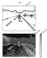
- Figure 2 shows an example of an image taken with a stereo camera.
- 21 and 22 are images taken by a stereo camera at the same time
- 21 is an original image taken by the camera (hereinafter referred to as “image”)
- 22 is an image taken by the left and right cameras, respectively.
- image an original image taken by the camera
- It is a parallax image calculated by using stereo matching processing from the captured original image.
- the color of the light and shade in the parallax image represents the value of the parallax of each pixel in the image.
- the magnitude of the parallax value is shown by shading.
- the three-dimensional object candidate region extraction means 2 extracts a three-dimensional object candidate region by grouping regions in which the parallax value is constant from the parallax (distance) image shown in 22.
- a specific extraction means for example, a histogram is created from the parallax image with the parallax values for each strip-shaped row divided by a certain width, and a three-dimensional object (a creature or an object including a person) is placed at the position of the parallax where the peak stands. If there is, there is known a means for extracting a three-dimensional object candidate region by grouping pixels having a value near the parallax value in the vertical and horizontal directions on the screen.
- the three-dimensional object candidate region extraction means 2 extracts the three-dimensional object candidate region (candidate region) indicating the region where the object exists from the image by grouping by the parallax associated with the pixel or the distance corresponding thereto. To do.
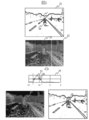
- Fig. 3 schematically shows the processing flow of this means. Take a motorcycle as an example of detection.
- 31 is an image input from a stereo camera
- 39 is a motorcycle.
- Reference numeral 32 denotes a parallax image in which the parallax value is represented by shading for each pixel.
- the parallax image is divided into strips of constant width as shown in 33. For each column, vote for the histogram with the parallax value of the pixels included in that column as the parallax on the horizontal axis.
- parallax histogram An example of a parallax histogram is shown in 34.
- a peak as shown in 35 appears at a specific parallax value.
- a threshold value proportional to the magnitude of the parallax value is set, and the pixels that take the value of the parallax range of the section 36 included in the threshold value are selected in the column.
- the grouping results are shown in 37 on 32 parallax images.
- the same grouped area is shown by 38 on the input image 31.
- the regions shown by 37 and 38 are regions extracted as three-dimensional object candidate regions.
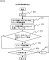
- FIG. 5 is a processing flow of the three-dimensional object candidate region extraction means 2 (CPU132), and FIG. 6 is a parallax image of an input for extracting a three-dimensional object candidate.
- CPU132 creates a parallax histogram from the distribution of parallax in column i.
- S53 is a process of acquiring the parallax value of the peak from the parallax histogram created in S52, extracting the area of the pixel that takes the parallax value from the column, and grouping it. It is grouped as a rectangle that covers the area where the peak parallax value is taken.
- (xs, ys) and (xe, ye) are the coordinates of the start and end points of the rectangle, respectively.
- the line segment connecting the start point and the end point is a rectangular diagonal line.
- the CPU 132 refers to column i-1 which is adjacent and has been subjected to the processing, and determines whether or not there is a group area in contact with the group created in column i. If there is, proceed to the processing of S55, and if not, proceed to the processing of S56.
- CPU132 integrates the divided group areas of column i and column i-1 in the group area update process.
- the CPU 132 determines whether the column reference counter i exceeds the maximum value of the column. If it does not exceed, the process proceeds to S57, and if it exceeds, it is assumed that the processing of all columns is completed, and the CPU 132 ends the processing.
- CPU132 increments the column reference counter i and moves on to the next column processing.
- the above is the processing flow of the three-dimensional object candidate region extraction means 2.
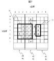
- the flow of this process will be specifically described with reference to the example of the parallax image of FIG.
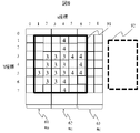
- an example will be described in which an image of 9 pixels in the x (horizontal) direction and 8 pixels in the y (vertical) direction is processed, and the columns are divided into 3 columns with 3 pixel widths each.
- the entire rectangle shown in the figure is the image area, and 61, 62, and 63 are strip-shaped columns corresponding to 33 in Fig. 3.
- the squares illustrated in 64 and 65 are the pixels that make up the image.
- the numerical value shown in the pixel as shown in 65 is an example of the parallax value. If it is blank as in 64, it is assumed that the parallax cannot be obtained because the distance is long.
- CPU132 refers to the column of column 61, which corresponds to column 0 of FIG.
- the CPU 132 creates a parallax histogram in column 61 and acquires the mode value as the peak parallax.
- the peak parallax value is the mode value 3.
- CPU132 acquires the peak parallax range and groups it.
- the CPU 132 creates a parallax histogram in column 62 and acquires the mode value as the peak parallax.
- the peak parallax value is the mode value 3.
- CPU132 acquires the peak parallax range and groups it.
- the CPU 132 determines whether or not the column i-1 has a group area in contact with the group of the column i. Comparing the groups in columns 62 and 61, the areas (1, 3) (2, 6) and (3, 3) (4, 6) are in contact with each other, so the process proceeds to S55.
- CPU132 updates the group area.
- the group areas of the columns are integrated.
- the group area after integration is (1,3) (4,6).
- the CPU 132 creates a parallax histogram in column 63 and acquires the mode value as the peak parallax.
- the peak parallax value is the mode value 4.
- CPU132 acquires the peak parallax range and groups it.
- the CPU 132 determines whether or not the column i-1 has a group area in contact with the group of the column i. Comparing the groups in columns 63 and 62, the areas (1, 3) (4, 6) and (6, 3) (6, 5) do not touch each other, so the process proceeds to S56.
- the group created during the above processing is the three-dimensional object candidate area.
- the three-dimensional object candidate area extracted by the process of the above three-dimensional object candidate area extraction means 2 is shown by the area surrounded by the thick rectangles 71 and 72 in FIG.
- the peak parallax value is a single value, but the values before and after the peak (peak parallax value +1 and peak parallax value -1) are also taken, and the range including peaks such as 2 or more and 4 or less is also acceptable. good.
- the above is an example of the means for realizing the three-dimensional object candidate region extraction means 2.
- the region extracted by the three-dimensional object candidate region extraction means 2 is an region for the detection target identification means 4 to determine whether the region is an object that seems to be a detection target (an object whose similarity to the detection target is equal to or higher than a predetermined value). Therefore, as shown in 37 and 38 of FIG. 3, it is necessary to cover the entire region of the three-dimensional object.
- the detection target candidate area expanding means 3 is a process of expanding the three-dimensional object candidate area extracted by the three-dimensional object candidate area extracting means 2 to a size equivalent to the detection target object by using a distance that can be calculated from the parallax of the area. ..
- Fig. 4 shows an example in which the same processing was performed on a distant motorcycle as in Fig. 3.
- 41 is the input image
- 42 in the image is the motorcycle.
- Reference numeral 43 denotes a parallax image calculated from the input image 41.
- a parallax histogram as shown in 47 is created for each of the strip-shaped columns 44, and the parallax peak 46 and the threshold interval 45 are created.
- the area in which the pixels that take the range of the parallax value in the section 45 after setting is grouped is shown in the 48 rectangles on the parallax image 43. Similarly, the grouping area is shown on the input image 41.
- the grouping range is determined with a constant threshold value for the peak parallax frequency, the grouping range is shown in 49. May not cover the entire three-dimensional object.
- the detection target candidate area expansion means 3 is a means for expanding the area so as to cover the entire area of the three-dimensional object when the absolute value of the parallax is small and the accuracy is low in such a distant place.
- a plurality of three-dimensional object candidate regions (groups) extracted by the three-dimensional object candidate region extraction means 2 are referred to in order, and the height and width of the detection target estimated from the parallax of each group and the actual height and width of the detection target. Compare the height and width of the group, and if the height or width of the group is smaller than the estimated value, expand the grouping area by changing the threshold value of the parallax value to be grouped, and exceed the estimated area. Is to expand the area to.
- the CPU 132 clears the reference counter k for sequentially referencing a plurality of three-dimensional object candidates (groups) created by the three-dimensional object candidate area extraction means 2.
- CPU132 acquires the parallax value of group k.
- a representative value is acquired by a method such as taking an average value or taking a maximum value.
- the CPU 132 calculates the height height_k and width width_k, which are the estimated sizes of the objects on the image, from the parallax acquired in S82.
- the actual height (for example, 160 cm) and width (for example, 100 cm) of the object are assumed in advance, and the object is at a position at a distance obtained from parallax. Calculate the size on the image.
- the calculation formulas for height_k (pixels) and width_k (pixels) are calculated by the following formulas using camera parameters.
- the detection target candidate area expansion means 3 (change part) is a detection target when it is assumed that the detection target (for example, a motorcycle) exists from the actual size (Height_Obj, Width_Obj) of the detection target and the distance Z to the distance Z.
- the image size (height_k, width_k) indicating the size on the image of (for example, a motorcycle) is calculated.
- the assumed height (typical height) and width (typical width) of the detection target are set according to the actual size of the object. Since the purpose is to expand to the area that covers the target, if the detection target varies in size due to age or individual differences such as pedestrians, setting the maximum value will produce an appropriate effect. Obtainable.
- CPU132 compares the actual width and height of group k with the width_k and height_k obtained by the processing of S83, and determines whether the actual width is smaller than width_k or the actual height is smaller than height_k. judge. If either the width or the height is smaller than the respective comparison values, the process proceeds to S85, and if both are larger, the process proceeds to S87.
- CPU132 is a process to change the threshold value of the grouped parallax of group k.
- the threshold value of the parallax extracted as a group is expanded, and the permissible range of the parallax values to be grouped is expanded.
- the CPU 132 re-executes the processing of the three-dimensional object candidate region extraction means 2 using the threshold value expanded in S85.
- the grouping area is widened and updated to change the parallax threshold and increase the tolerance. After updating, the process returns to S84 and the size of the group is determined.
- CPU132 increments the counter k for the number of groups.
- CPU132 determines whether k exceeds the maximum number of groups. If it does not exceed, proceed to S82 and execute the processing of the next group. If it exceeds the limit, it is assumed that the processing of all groups has been completed, and the CPU 132 terminates this processing.
- the detection target candidate area expanding means 3 changes the size of the three-dimensional object candidate area (candidate area) to the image size (height_k, width_k) or more.
- the detection target candidate area expanding means 3 widens the range of parallax or distance in grouping until the size of the three-dimensional object candidate area (candidate area) exceeds the image size (height_k, width_k). Then, the three-dimensional object candidate region extraction means 2 (extracting unit) is made to re-extract the three-dimensional object candidate region. Further, the detection target identification means 4 (identification unit) identifies whether the object in the re-extracted three-dimensional object candidate region (candidate region) is a detection target (for example, a motorcycle).
- the size of the three-dimensional object candidate area can be made larger than the image size by grouping adjacent groups having substantially the same distance. As a result, it is possible to improve the identification accuracy of the detection target while suppressing the processing load.
- the processing of the detection target candidate area expansion means 3 By repeating the process from S84 to S86, the range of parallax values to be grouped is expanded, the area is expanded, and the area is expanded until it becomes larger than width_k and height_k.
- FIG. 9 shows the result of expanding the three-dimensional object candidate region extracted by the three-dimensional object candidate region extracting means 2 shown in FIG. 7 by the detection target candidate region expanding means 3. It can be seen that what was divided into group 71 and group 72 in FIG. 7 is integrated into group 91 in FIG. 9 to form a large group.
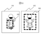
- Figure 10 shows an example of the detection target candidate area before and after expanding the area with the detection target candidate area expansion means 3.
- 101 is an example before expansion and 102 is an example after expansion.
- the detection target candidate area 103 does not cover the area of the detection target (motorcycle and driver), but after the expansion, the detection target candidate area 104 covers the detection target area.
- the processing of the detection target candidate area expanding means 3 even if the candidate area of the three-dimensional object does not cover the entire detection target area, it can be appropriately expanded to a size that includes the detection target.
- the detection target identification means 4 is a means for detecting whether or not a specific area is a detection target by pattern matching, a classifier by machine learning, or the like.
- the three-dimensional object candidate region extraction means 2 extracts, and the region expanded by the detection target candidate region expansion means 3 is subjected to identification processing.
- the three-dimensional object candidate region extraction means 2 extracts the region as shown in 103 by parallax grouping. A case occurs.
- the identification process does not work well because the area does not include the feature for identifying the object because the entire detection target area is not covered. ..
- the size is expanded to the size equivalent to the assumed detection target. Therefore, as shown in 104, the area is expanded to include the detection target area. It has the effect of being able to perform the identification process well.
- the detection target identification means 4 identifies whether the object in the three-dimensional object candidate region (candidate region) whose size has been changed is the detection target (for example, a motorcycle). As a result, the detection target is included in the three-dimensional object candidate region (candidate region), so that the identification accuracy of the detection target can be improved.
- the above is the first embodiment of the object detection device according to the present invention.
- the three-dimensional object candidate area (candidate area) is expanded to a size equivalent to the detection object by the detection target candidate area expansion means 3, thereby performing the latter stage.
- the identification process by the detection target identification means 4 can be performed well, and since the area is expanded based on the distance that can be estimated from the parallax, the effect is that the processing load is not increased without expanding to an unnecessarily large size. There is also.
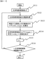
- FIG. 11 is a diagram showing a flow of processing for explaining a second embodiment of the detection target candidate region expanding means 3 of the object detection device according to the second embodiment of the present invention.
- this embodiment there are a plurality of three-dimensional object candidate regions detected by the three-dimensional object candidate region extraction means 2 in the image, and each of them is processed in order.
- the CPU 132 sets the reference counter l of the three-dimensional object candidate area to the initial value of 0.
- the CPU 132 acquires the parallax (representative value) of the three-dimensional object candidate area l.
- CPU132 in S113 calculates the size width_l and height_l of the object on the image from the parallax acquired in S112. This calculation method is the same as the processing of S83 in FIG. 8, and is calculated using Eqs. (1) and (2).
- CPU 132 expands the area of height_l above and below the three-dimensional object candidate area and width_l to the left and right using the height_l and width_l calculated in S113.
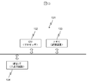
- the enlargement method will be described with reference to FIG.
- the detection target 122 (motorcycle and driver) exists in the image 121 of FIG. 12, and the region 123 consisting of the vertices 126, 127, 128, and 129 is detected by the three-dimensional object candidate region extraction means 2.
- the area 12a is the result of expanding the width_l and height_l calculated in S113 to the top, bottom, left, and right of the vertices 126, 127, 128, and 129, respectively.
- the detection target candidate area expanding means 3 has the width_l of the image size (width_l, height_l) and the three-dimensional object candidate area (candidate area) for each of the positive and negative directions of the horizontal axis of the image.
- the size of the three-dimensional object candidate area is changed so that the width of the three-dimensional object candidate area increases by the difference ⁇ W from the width of the image, and the image size (width_l, height_l) is changed for each of the positive and negative directions of the vertical axis of the image.
- the size of the three-dimensional object candidate area is changed so that the vertical width of the three-dimensional object candidate area is increased by the difference ⁇ H between the vertical width height_l and the vertical width of the three-dimensional object candidate area (candidate area).
- the size of the three-dimensional object candidate region can be made larger than the image size (width_l, height_l) calculated by the equations (1) and (2) even if the distances are almost equal and there are no adjacent groups. it can.
- the identification accuracy of the detection target can be improved regardless of the presence or absence of adjacent groups having substantially the same distance.
- the CPU 132 increments the reference counter l of the three-dimensional object candidate area.
- the CPU 132 determines whether or not the reference counter l exceeds the maximum number of three-dimensional object candidate regions (maximum value of the reference counter). If it does not exceed, it is assumed that there is an unprocessed three-dimensional object candidate area, and the process proceeds to S112. If it exceeds, CPU 132 ends this process.
- the second embodiment of the detection target candidate area expansion means 3 When a large amount of parallax cannot be obtained as in the first embodiment, the expected sizes width_l and height_l of the detection target are expanded centering on the three-dimensional object candidate region. By expanding up, down, left, and right, it is possible to cover the entire detection target regardless of where the three-dimensional object candidate area before expansion is actually detected.
- the first embodiment and the second embodiment have been described as separate embodiments, both may be implemented at the same time. That is, after expanding at the stage of grouping by parallax according to the first embodiment and creating a three-dimensional object candidate region by grouping, the region is larger than the size of the detection target object by using the second embodiment. If it is small, expand the area appropriately. By taking the above form, it is possible to appropriately expand the detection target area to a size suitable for the subsequent identification process even for a three-dimensional object in a region where parallax is difficult to obtain.
- the detection target candidate area expanding means 3 may not be performed on all the three-dimensional object candidate areas, but may be performed only on a distant place where it is difficult to obtain an appropriate three-dimensional object area by parallax grouping.
- the detection target candidate area expanding means 3 (change unit) calculates the size of the three-dimensional object candidate area (candidate area) by the equations (1) and (2) when the distance Z is a long distance equal to or more than the threshold value. Change the image size (height_k, width_k) or larger.
- the detection target candidate area expanding means 3 (changed part) and the detection target identification are identified.
- the processing load of means 4 (identification unit) can be reduced.
- the present invention is not limited to the above-mentioned examples, and includes various modifications.
- the above-described embodiment has been described in detail in order to explain the present invention in an easy-to-understand manner, and is not necessarily limited to those having all the described configurations.
- it is possible to replace a part of the configuration of one embodiment with the configuration of another embodiment and it is also possible to add the configuration of another embodiment to the configuration of one embodiment.
- the function of the object detection device is realized by the CPU 132 of the microcomputer, but it may be realized by the CPU mounted on the stereo camera or the circuit.
- the three-dimensional object candidate area extraction means 2 (extraction unit), the detection target candidate area expansion means 3 (change unit), and the detection target identification means 4 (identification unit) are logic circuits such as FPGA (Field-Programmable Gate Array). It may be composed of. As a result, various functions can be realized in terms of hardware by using a logic circuit.
- the detection target is a motorcycle or a person, but other objects may be used.
- each of the above configurations, functions, etc. may be realized by hardware, for example, by designing a part or all of them with an integrated circuit. Further, each of the above configurations, functions, and the like may be realized by software by the processor interpreting and executing a program that realizes each function. Information such as programs, tables, and files that realize each function can be stored in a memory, a storage device such as a hard disk or SSD (Solid State Drive), or a storage medium such as an IC card, SD card, or DVD.
- a storage device such as a hard disk or SSD (Solid State Drive)
- a storage medium such as an IC card, SD card, or DVD.
- the embodiment of the present invention may have the following aspects.
- an object detection device that identifies a specific object from an image
- an image input means for inputting an image taken by a stereo camera
- a three-dimensional object candidate area extraction means for extracting a three-dimensional object candidate area from distance information on the image
- a detection target From the size information and the distance information of the three-dimensional object candidate area, the estimated detection target size on the screen is calculated, and the detection target candidate area expansion means for expanding the target candidate area and the image information of the detection target candidate area are used to determine the detection target likeness.
- An object detection device including a detection target identification means for determining.
- the detection target candidate region expanding means sets them as one three-dimensional object candidate region.
- the detection target candidate area expanding means is a total area of four regions expanded to the assumed size of the detection target on the image, starting from each of the four rectangular vertices of the three-dimensional object candidate region. Object detection device.
- the object candidate area can be set appropriately even in a distant place where the distance measurement accuracy is poor, the performance of the identification processing in the subsequent stage can be improved, and the processing load can be suppressed to a small value.
Abstract
検知対象が遠方にある場合でも、検知対象の識別精度を向上することができる物体検出装置を提供する。立体物候補領域抽出手段2は、画素に関連付けられる視差若しくはそれに対応する距離によってグルーピングすることで、物体が存在する領域を示す立体物候補領域を画像から抽出する。検知対象候補領域拡大手段3は、検知対象の実サイズ(Height_Obj,Width_Obj)と距離Zから距離Zに検知対象(例えば、バイク)が存在すると仮定した場合の検知対象の画像上のサイズを示す画像サイズ(height_k,width_k)を算出し、立体物候補領域のサイズを画像サイズ以上に変更する。検知対象識別手段4は、サイズが変更された立体物候補領域内の物体が検知対象であるかを識別する。
Description
本発明は、物体検出装置に関する。
自動車の安全支援や、自動運転の実現のため、画像センサにより特定の物体を識別する機能が求められている。物体識別には、大量の特定物体の画像を学習させて作成した識別器を用いて、画像中に特定物体があるか否かを判定する方法が一般に用いられる。
識別器を用いた物体識別の実施のためには、撮影画像中のどこに対象物がいるかが既知でない場合には、画面全体を、識別器の位置と大きさを変更しながら走査するラスタスキャンという方式を使うことが知られている。ラスタスキャン方式は処理コストが膨大であり、実時間処理が求められる車載の画像センサにおいては現実的でない。そのため、ステレオカメラにより物体の存在する領域を候補領域として抽出し、その領域に対して識別を実施する方式が従来用いられている。
ステレオカメラにより取得できる視差に基づき候補領域を抽出する方法が開示されている(例えば、特許文献1参照)。
特許文献1には、「撮像領域についての視差画像情報を生成する視差画像情報生成手段と、前記視差画像情報生成手段が生成した視差画像情報に基づいて、前記撮像画像を左右方向に複数分割して得られる各列領域内における視差値の頻度分布を示す視差ヒストグラム情報を生成する視差ヒストグラム情報生成手段と、前記視差ヒストグラム情報生成手段が生成した視差ヒストグラム情報に基づいて、前記撮像画像の左右方向で近接していて、かつ、所定値以上の頻度をもつ視差値の値が近接している画像領域を、検出対象物を映し出す検出対象物画像領域の候補領域として選別し、選別した候補領域の中から所定の特定条件に従って検出対象物画像領域を特定する検出対象物画像領域特定手段とを有し」との記載がある。
しかし、識別対象物体が遠方にある場合、視差の値が小さくなるために、計測誤差の影響を受けやすくなり、候補領域が正確に求まらず、特に候補領域が対象物領域より小さい領域しか求まらずに検知対象物領域全体を包括しない場合に、候補領域に対して実施する識別処理が良好に働かない問題があった。
特許文献1には、検出対象が遠方にある場合の対策については言及がない。
本発明の目的は、検知対象が遠方にある場合でも、検知対象の識別精度を向上することができる物体検出装置を提供することにある。
上記目的を達成するために、本発明は、画素に関連付けられる視差若しくはそれに対応する距離によってグルーピングすることで、物体が存在する領域を示す候補領域を画像から抽出する抽出部と、検知対象の実サイズと前記距離から前記距離に前記検知対象が存在すると仮定した場合の前記検知対象の前記画像上のサイズを示す画像サイズを算出し、前記候補領域のサイズを前記画像サイズ以上に変更する変更部と、サイズが変更された前記候補領域内の前記物体が前記検知対象であるかを識別する識別部と、を備える。
本発明によれば、検知対象が遠方にある場合でも、検知対象の識別精度を向上することができる。上記した以外の課題、構成及び効果は、以下の実施形態の説明により明らかにされる。
以下、図面等を用いて、本発明の実施形態について説明する。以下の説明は本発明の内容の具体的な例を示すものであり、本発明がこれらの説明に限定されるものではなく、本明細書に開示される技術的思想の範囲内において当業者による様々な変更および修正が可能である。また、本発明を説明するための全図において、同一の機能を有するものは、同一の符号を付け、その繰り返しの説明は省略する場合がある。
(第一の実施例)
図1は、本発明の第一の実施例による物体検出装置の構成を示すブロック図である。なお、物体検出装置は、ステレオカメラ(カメラ)によって撮像された画像から特定の物体(例えば、バイク、歩行者等)を検出する装置である。
図1は、本発明の第一の実施例による物体検出装置の構成を示すブロック図である。なお、物体検出装置は、ステレオカメラ(カメラ)によって撮像された画像から特定の物体(例えば、バイク、歩行者等)を検出する装置である。
図1の物体検出装置は、カメラから取得した画像を入力する画像入力手段1と、画像入力手段1で入力された画像中の立体物候補領域抽出手段2と、抽出された立体物候補領域の距離情報から、検知対象の大きさを網羅する大きさに領域を拡大する検知対象候補領域拡大手段3と、検知対象候補領域拡大手段3で決定した領域に、特定対象であるか否かの識別をする検知対象識別手段4からなる。
なお、図13に示すように、物体検出装置は、例えば、マイコン131であり、CPU132(Central Processing Unit)等のプロセッサ、メモリ133等の記憶装置、通信I/F134等の入出力回路から構成される。本実施例では、CPU132は、メモリ133に記憶されたプログラムを実行することにより、立体物候補領域抽出手段2、検知対象候補領域拡大手段3、検知対象識別手段4として機能する。また、CPU132は、通信I/F134を介してステレオカメラから画像を受信することにより、画像入力手段1として機能する。
換言すれば、立体物候補領域抽出手段2(抽出部)、検知対象候補領域拡大手段3、及び検知対象識別手段4(識別部)は、CPU132(プロセッサ)で構成される。ここで、画素と、視差若しくはそれに対応する距離とは、対応付けてメモリ133に記憶される(視差画像又は距離画像)。これにより、CPU132(プロセッサ)を用いてソフトウェア的に種々の機能を実現することができる。
続いて、第一の実施例の構成要素について順に説明する。
画像入力手段1は、車両前方に設置したカメラから、画像を取得する手段である。
立体物候補領域抽出手段2は、画像入力手段1から入力した画像中で、立体物が存在する候補領域を抽出する手段である。
立体物候補領域抽出手段2の処理につき、具体的に説明する。立体物候補領域抽出手段2の実現手段には様々な方法があるが、本実施例ではステレオカメラを用いて立体物候補領域を抽出する例につき説明する。
ステレオカメラは、左右2台のカメラを持ち、これらの視差を用いて、被写体との距離を測定する装置である。画像入力手段では、ステレオカメラ1の左右二台のカメラで撮影した画像と、複数の画像から求まる視差画像もしくは距離画像の二種類を入力する。図2に、ステレオカメラで撮影される画像の例を示す。
図2中、21と22は、それぞれ同時刻にステレオカメラで撮影した画像であり、21はカメラで撮影された原画像(以降、「画像」とする)であり、22は左右のカメラそれぞれで撮影された原画像よりステレオマッチング処理を用いて算出した視差画像とする。視差画像中の濃淡の色で、画像中の各画素の視差の値を表す。23のチャートに示すように、視差の値の大小を濃淡で示している。
立体物候補領域抽出手段2では、22に示す視差(距離)画像から、視差の値が一定である領域をグルーピングすることにより立体物候補領域を抽出する。具体的な抽出手段として、例えば、視差画像から一定の幅で区切った短冊状の列ごとの視差値でヒストグラムを作成し、ピークが立つ視差の位置に立体物(人を含む生物又は物体)があるとし、当該視差値付近の値を採る画素の、画面上の縦横方向のグルーピングにより、立体物候補領域を抽出する手段が知られている。
すなわち、立体物候補領域抽出手段2(抽出部)は、画素に関連付けられる視差若しくはそれに対応する距離によってグルーピングすることで、物体が存在する領域を示す立体物候補領域(候補領域)を画像から抽出する。
本手段の処理の流れを図3に模式的に示す。尚、検知対象としてバイクを例に取る。図中、31はステレオカメラから入力された画像であり、39がバイクである。32は視差の値を画素ごとに濃淡で表した視差画像である。視差画像に対し33に示すように一定幅の列に短冊状に区切る。列ごとにその列に含まれる画素の視差値を横軸を視差としたヒストグラムに投票する。
視差ヒストグラムの例を34に示す。当該列内に立体物がある場合には特定の視差値に35に示すようなピークが立つ。視差を求める際の誤差も考慮するため、視差値の大きさごとに比例するしきい値を設定し、そのしきい値に含まれる区間36の視差の範囲の値を採る画素を、当該列中と、隣接する左右の列内でグルーピングする。グルーピングした結果を32の視差画像上の37に示す。また同じグルーピングした領域を入力画像31上に38で示す。これら37、38で示す領域が立体物候補領域として抽出した領域である。
<立体物候補領域抽出>
立体物候補領域抽出手段2の詳細な処理を図5と図6を用いて説明する。図5は立体物候補領域抽出手段2(CPU132)の処理の流れ、図6は、立体物候補抽出をする入力の視差画像である。
立体物候補領域抽出手段2の詳細な処理を図5と図6を用いて説明する。図5は立体物候補領域抽出手段2(CPU132)の処理の流れ、図6は、立体物候補抽出をする入力の視差画像である。
図5のS51でCPU132は、図3の33で示す列を参照するカウンタを0クリアする。
S52でCPU132は列iの視差の分布から、視差ヒストグラムを作成する。
S53はS52で作成した視差ヒストグラムから、ピークの視差値を取得し、当該列から、その視差値を採る画素の領域を抽出し、グループ化する処理である。ピークの視差値を採る領域を包括する矩形としてグループ化される。ここで、(xs,ys)と(xe,ye)はそれぞれ、矩形の始点と終点の座標である。始点と終点を結ぶ線分は矩形の対角線となる。
S54でCPU132は、隣接し、且つ当該処理を実施済の列i-1を参照し、列iで作成したグループに接したグループ領域があるか否かを判定する。ある場合はS55の処理に進み、ない場合はS56の処理に進む。
S55でCPU132は、グループ領域の更新処理で、列iと列i-1の分割されたグループ領域を統合する。
S56でCPU132は、列の参照カウンタiが、列の最大値を超えていないかを判定する。超えていない場合はS57に進み、超えている場合はすべての列の処理が完了したとし、CPU132は処理を終了する。
S57でCPU132は、列の参照カウンタiをインクリメントし、次の列の処理に移る。
以上が立体物候補領域抽出手段2の処理の流れである。この処理の流れを、図6の視差画像の例を用いて具体的に説明する。簡単のため、x(横)方向9画素、y(縦)方向8画素の画像で、列は幅3画素ずつに3列で区切って処理する例で説明する。
図中に示した矩形全体が画像領域であり、61,62、63は図3の33に相当する短冊状の列である。64,65に例示する正方形が画像を構成する画素である。65に示すように画素中に示した数値は視差値の例である。64のように空欄の場合は距離が遠い等で視差が取得できなかったとする。
図5の処理の流れに従い立体物候補領域抽出処理の具体例を説明する。
S51の処理で、CPU132は、図6の列0に当たる列61の列を参照する。
S52の処理で、CPU132は、列61の視差ヒストグラムを作成し、最頻値をピーク視差として取得する。列61の場合、ピーク視差値は最頻値の3となる。
S53の処理で、CPU132は、ピーク視差範囲を取得し、グループ化する。列61の場合ピーク視差値の存在する範囲の矩形領域は、(x始点座標,y始点座標)(x終点座標,y終点座標)=(1,3)(2,6)となる。
S54の判定は、列61は開始列のため、スキップする。
S56の判定で、列61は列最大値でないので、CPU132は、S57に進み列参照カウンタを1とする。
S52の処理で、CPU132は、列62の視差ヒストグラムを作成し、最頻値をピーク視差として取得する。列62の場合、ピーク視差値は最頻値の3となる。
S53の処理で、CPU132は、ピーク視差範囲を取得し、グループ化する。列62の場合ピーク視差値の存在する範囲の矩形領域は、(x始点座標,y始点座標)(x終点座標,y終点座標)=(3,3)(4,6)となる。
S54の判定で、CPU132は、列i-1に、列iのグループに接したグループ領域があるか否かを判定する。当該列62と列61のグループを比較すると、(1,3)(2,6)と(3,3)(4,6)の領域は接しているため、S55の処理に進む。
S55の処理で、CPU132は、グループ領域を更新する。S54の判定でグループ領域が接していると判定したとき、列のグループ領域を統合する。この例の場合、統合後のグループ領域は(1,3)(4,6)となる。
S56の判定で、列62は列最大値でないので、CPU132は、S57に進み列参照カウンタを2とする。
S52の判定で、CPU132は、列63の視差ヒストグラムを作成し、最頻値をピーク視差として取得する。列63の場合、ピーク視差値は最頻値の4となる。
S53の処理で、CPU132は、ピーク視差範囲を取得し、グループ化する。列61の場合ピーク視差値の存在する範囲の矩形領域は、(x始点座標,y始点座標)(x終点座標、y終点座標)=(6,3)(6,5)となる。
S54の判定で、CPU132は、列i-1に、列iのグループに接したグループ領域があるか否かを判定する。当該列63と列62のグループを比較すると、(1,3)(4,6)と(6,3)(6,5)の領域は接していないため、S56の処理に進む。
S56の判定で、列62は列最大値なので、CPU132は、本処理を終了とする。
以上の処理中で作成されたグループが立体物候補領域である。
以上の立体物候補領域抽出手段2の処理により抽出された立体物候補領域を図7の71、72の太い矩形で囲んだ領域で示す。尚、簡単のためピーク視差値は単一の値としたが、ピークの前後の値(ピーク視差値+1及びピーク視差値-1)も採るとし2以上4以下等のピークを含む範囲としても良い。
以上が、立体物候補領域抽出手段2の実現手段の一例である。立体物候補領域抽出手段2で抽出した領域は、検知対象識別手段4で、その領域が検知対象らしい物体(検知対象に対する類似度が所定値以上となる物体)であるかを判定する領域となるため、図3の37、38に示すように、立体物の領域全体を包括した領域である必要がある。
<検知対象候補領域拡大>
次に、検知対象候補領域拡大手段3につき説明する。検知対象候補領域拡大手段3は、立体物候補領域抽出手段2で抽出した立体物候補領域を、その領域の視差から算出できる距離を用いて、検知対象物相当の大きさに拡大する処理である。
次に、検知対象候補領域拡大手段3につき説明する。検知対象候補領域拡大手段3は、立体物候補領域抽出手段2で抽出した立体物候補領域を、その領域の視差から算出できる距離を用いて、検知対象物相当の大きさに拡大する処理である。
検知対象候補領域拡大手段3の処理につき、図4を用いて説明する。
図4は、図3と同様に、遠方にあるバイクに対して同様の処理を実施した例を図4に示す。41が入力画像であり、画像中42がバイクである。43は入力画像41から算出した視差画像であり、図3の例と同様に短冊状の列44毎に、47に示すような視差ヒストグラムを作成し、視差のピーク46と、しきい値区間45を設定した上で区間45の視差の値の範囲を採る画素をグルーピングした領域を視差画像43上の48の矩形に示す。同様に入力画像41上にグルーピング領域を示す。
図3と図4の例を比較すると、図3では検知対象のバイクが近距離にあるため、視差ヒストグラム34に示すように検知対象物領域(視差ピーク)の視差の絶対値が大きく、図4では検知対象が遠距離にあるため視差ヒストグラム47に示すように検知対象物領域(視差ピーク)の視差の絶対値が小さい。図3のように近傍で視差の絶対値が大きい場合は、視差の絶対値に対する計測誤差の値が小さいため、一定しきい値でグルーピング範囲を決定することで、図3の38に示すように立体物領域全体を検出することができる。
一方、遠方で視差の絶対値が小さい場合は、視差の絶対値に対する計測誤差の割合が高くなるため、視差頻度ピークに対する一定しきい値でグルーピング範囲を決めると、49に示すように、グルーピング範囲が立体物全体を包括しない場合がある。
検知対象候補領域拡大手段3は、このように遠方で視差の絶対値が小さく、精度が低い場合に、立体物の領域全体を包括する領域になるよう領域を拡大する手段である。
本処理は、立体物候補領域抽出手段2で抽出された複数の立体物候補領域(グループ)を順に参照し、それぞれのグループの視差から推定される、検知対象の高さ、幅と、実際のグループの高さと幅を比較し、グループの高さもしくは幅が、推定値より小さい場合に、グループ化する視差の値のしきい値を変更することでグループ化領域を拡大し、推定領域相当以上に領域を拡大することである。
検知対象候補領域拡大手段3(CPU132)の処理の流れを図8を用いて説明する。
S81でCPU132は、立体物候補領域抽出手段2で作成された複数の立体物候補(グループ)を順に参照するための参照カウンタkを0クリアする。
S82でCPU132は、グループkの視差値を取得する。視差値は、複数の視差が含まれる領域の場合、平均値を採る、最大値を採るなどの方法で代表値を取得する。
S83でCPU132は、S82で取得した視差から、画像上の対象物の推定サイズである高さheight_k、幅width_kを算出する。
ここでは、対象物(例えば、バイク)の実際の高さ(例えば、160cm)と幅(例えば、100cm)をあらかじめ仮定しておき、その対象物が、視差から得られる距離の位置にいた場合の画像上の大きさを算出する。height_k(画素)とwidth_k(画素)の算出式はカメラパラメータを用いて下記の式により求められる。
height_k = (Height_Obj * f)/(Z×w) …(1)
width_k = (Width_Obj * f)/(Z×w) …(2)
ただし、
Height_Obj: 検知対象の仮定した高さ(mm)
Width_Obj: 検知対象の仮定した幅(mm)
f:焦点距離(mm)
Z:距離(mm)
w:画素ピッチ(mm)
である。
width_k = (Width_Obj * f)/(Z×w) …(2)
ただし、
Height_Obj: 検知対象の仮定した高さ(mm)
Width_Obj: 検知対象の仮定した幅(mm)
f:焦点距離(mm)
Z:距離(mm)
w:画素ピッチ(mm)
である。
換言すれば、検知対象候補領域拡大手段3(変更部)は、検知対象の実サイズ(Height_Obj,Width_Obj)と距離Zから距離Zに検知対象(例えば、バイク)が存在すると仮定した場合の検知対象(例えば、バイク)の画像上のサイズを示す画像サイズ(height_k,width_k)を算出する。
検知対象の仮定した高さ(代表的な高さ)と幅(代表的な幅)は、その物体の実際の大きさにより設定する。対象を包括する領域に拡大するのが目的であるので、検知対象がたとえば歩行者など、年齢や個体差などにより大きさにばらつきがある場合には、最大値を設定することで適切な効果を得ることができる。
S84でCPU132は、グループkの実際の幅と高さを、S83の処理で求めたwidth_kとheight_kと比較し、実際の幅がwidth_kより小さいか若しくは実際の高さがheight_kより小さいか否かを判定する。幅と高さのいずれかがそれぞれの比較値より小さければS85の処理に進み、どちらも大きければS87に進む。
S85でCPU132は、グループkのグループ化した視差のしきい値を変更する処理である。グループkに含まれる視差値を参照し、グループとして抽出する視差のしきい値を拡大し、グループ化する視差値の許容範囲を広げる。
S86でCPU132は、S85で拡大したしきい値を用いて、立体物候補領域抽出手段2の処理を再度実施する。視差しきい値を変更し許容範囲を広げるため、グループ化領域が広くなって更新される。更新した後はS84の処理に戻り、グループの大きさの判定を実施する。
S84でnoの場合、S87の処理に進む。
S87でCPU132は、グループ数のカウンタkをインクリメントする。
S88でCPU132は、kがグループ数の最大値を超えているか否かを判定する。超えていなければS82にすすみ次のグループの処理を実施する。超えていればすべてのグループの処理が終了したとしCPU132は本処理を終了する。
このようにして、検知対象候補領域拡大手段3(変更部)は、立体物候補領域(候補領域)のサイズを画像サイズ(height_k,width_k)以上に変更する。
本実施例では、検知対象候補領域拡大手段3(変更部)は、立体物候補領域(候補領域)のサイズが画像サイズ(height_k,width_k)を超えるまで、グルーピングにおける視差若しくは距離の範囲を広くして、立体物候補領域抽出手段2(抽出部)に立体物候補領域を再抽出させる。また、検知対象識別手段4(識別部)は、再抽出された立体物候補領域(候補領域)内の物体が検知対象(例えば、バイク)であるかを識別する。
これにより、距離がほぼ等しい隣接するグループをまとめて立体物候補領域(候補領域)のサイズを画像サイズ以上とすることができる。その結果、処理負荷を抑えつつ検知対象の識別精度を向上することができる。
以上が検知対象候補領域拡大手段3の処理である。S84からS86までの処理を繰り返すことで、グループ化する視差値の値の範囲を広げ、領域を拡大し、width_kとheight_kより大きくなるまで領域を広げる処理である。
遠方は、視差の絶対値が小さいため、物体の視差の誤差範囲と、背景の視差との境界が明確でない。このため、ピーク視差値によってグルーピングされる領域を開始領域とし、検知対象の大きさに到達するまでの視差範囲を拡大することで、適切な視差範囲に調整する処理である。
図9に、図7に示す立体物候補領域抽出手段2で抽出した立体物候補領域を検知対象候補領域拡大手段3で拡大した結果を示す。図7でグループ71とグループ72に分かれていたものが、図9ではグループ91に統合されサイズの大きいグループになっていることがわかる。
検知対象候補領域拡大手段3で領域を拡大する前後の検知対象候補領域の例を図10に示す。101が拡大前、102は拡大後の例である。拡大する前は、検知対象候補領域103は、検知対象(バイクと運転者)の領域をカバーしていないが、拡大後は、検知対象候補領域104は検知対象の領域を包括している。
以上のように、検知対象候補領域拡大手段3の処理により、立体物の候補領域が検知対象領域全体を包括していない場合も、検知対象を包括する大きさに適切に拡大することができる。
<検知対象識別>
検知対象識別手段4は、パタンマッチング、機械学習による識別器などにより、特定の領域が検知対象であるか否かを検出する手段である。本発明では、立体物候補領域抽出手段2で抽出し、検知対象候補領域拡大手段3で拡大した領域に対して識別処理をする。図10で説明したように、遠方で視差の絶対値が小さく、背景との区別がしにくい場合には、立体物候補領域抽出手段2で視差のグルーピングにより103に示すような領域が抽出されるケースが発生する。この場合、103の領域に対して識別処理を実施すると、検知対象物領域全体を包括していないために、対象物を識別する特徴が領域に含まれないために、識別処理が良好に働かない。これに対して、検知対象候補領域拡大手段3で拡大した結果、想定する検知対象相当の大きさに拡大しているために、104に示すように検知対象の領域を包括するサイズの領域に拡大できており、識別処理も良好に処理できる効果がある。
検知対象識別手段4は、パタンマッチング、機械学習による識別器などにより、特定の領域が検知対象であるか否かを検出する手段である。本発明では、立体物候補領域抽出手段2で抽出し、検知対象候補領域拡大手段3で拡大した領域に対して識別処理をする。図10で説明したように、遠方で視差の絶対値が小さく、背景との区別がしにくい場合には、立体物候補領域抽出手段2で視差のグルーピングにより103に示すような領域が抽出されるケースが発生する。この場合、103の領域に対して識別処理を実施すると、検知対象物領域全体を包括していないために、対象物を識別する特徴が領域に含まれないために、識別処理が良好に働かない。これに対して、検知対象候補領域拡大手段3で拡大した結果、想定する検知対象相当の大きさに拡大しているために、104に示すように検知対象の領域を包括するサイズの領域に拡大できており、識別処理も良好に処理できる効果がある。
換言すれば、検知対象識別手段4(識別部)は、サイズが変更された立体物候補領域(候補領域)内の物体が検知対象(例えば、バイク)であるかを識別する。これにより、立体物候補領域(候補領域)に検知対象が包括されるため検知対象の識別精度を向上することができる。
以上が、本発明による物体検出装置の第一の実施形態である。遠方の物体が視差のグルーピングにより領域全体が良好に抽出できない場合に、検知対象候補領域拡大手段3で立体物候補領域(候補領域)を検出対象物相当の大きさに拡大することにより、後段の検知対象識別手段4での識別処理を良好に実行できる効果がある、また、視差から推定できる距離に基づき領域を拡大するため、必要以上の大きさに拡大することがなく処理負荷を増やさない効果もある。
以上説明したように、本実施例によれば、検知対象が遠方にある場合でも、検知対象の識別精度を向上することができる。
(第二の実施例)
図11は、本発明の第二の実施例による物体検出装置の検知対象候補領域拡大手段3の第二の実現形態を説明する処理の流れを示す図である。本実施例では、画像内に、立体物候補領域抽出手段2で検知した複数の立体物候補領域が存在し、それぞれにつき順に処理をする。
図11は、本発明の第二の実施例による物体検出装置の検知対象候補領域拡大手段3の第二の実現形態を説明する処理の流れを示す図である。本実施例では、画像内に、立体物候補領域抽出手段2で検知した複数の立体物候補領域が存在し、それぞれにつき順に処理をする。
S111でCPU132は、立体物候補領域の参照カウンタlを初期値の0とする。
S112でCPU132は、立体物候補領域lの視差(代表値)を取得する。
S113でCPU132は、S112で取得した視差から、画像上の対象物のサイズwidth_l,height_lを算出する。この算出方法は、図8のS83の処理と同じであり、式(1)および式(2)を用いて算出する。
S114でCPU132は、S113で算出したheight_lとwidth_lを用いて、立体物候補領域の上下にheight_l,左右にwidth_lの領域を拡大する。拡大方法を図12を用いて説明する。図12の画像121中に検知対象122(バイク及び運転者)が存在しており、立体物候補領域抽出手段2で、頂点126,127,128,129からなる領域123が検出されている。この領域に対して、S113で算出したwidth_l,height_lを、頂点126,127,128,129を起点としてそれぞれ上下左右に拡大した結果が領域12aである。
換言すれば、検知対象候補領域拡大手段3(変更部)は、画像の横軸の正方向、負方向のそれぞれについて、画像サイズ(width_l,height_l)の横幅width_lと立体物候補領域(候補領域)の横幅との差分ΔWだけ立体物候補領域の横幅が大きくなるように立体物候補領域のサイズを変更し、画像の縦軸の正方向、負方向のそれぞれについて、画像サイズ(width_l,height_l)の縦幅height_lと立体物候補領域(候補領域)の縦幅との差分ΔHだけ立体物候補領域の縦幅が大きくなるように立体物候補領域のサイズを変更する。
これにより、距離がほぼ等しく且つ隣接するグループがなくても立体物候補領域(候補領域)のサイズを式(1)、(2)によって算出される画像サイズ(width_l,height_l)以上とすることができる。その結果、距離がほぼ等しく且つ隣接するグループの有無にかかわらず、検知対象の識別精度を向上することができる。
S115でCPU132は、立体物候補領域の参照カウンタlをインクリメントする。
S116でCPU132は、参照カウンタlが立体物候補領域数最大値(参照カウンタの最大値)を超えたか否かを判定する。超えていない場合は未処理の立体物候補領域があるとし、S112の処理に進む。超えている場合、CPU132は本処理を終了する。
以上が検知対象候補領域拡大手段3の第二の実施形態である。第一の実施形態のように、視差が多く得られない場合に、立体物候補領域を中心に検知対象の想定される大きさwidth_l,height_lを拡大する。上下左右に拡大することで、拡大前の立体物候補領域が、実際の検知対象のどこについていても、検知対象全体を包括可能である。
以上が、本発明による物体検出装置の実施形態である。
第一の実施形態と第二の実施形態を別の実施例として説明したが、両方を同時に実施しても良い。すなわち、第一の実施形態により視差によるグループ化の段階での拡大を実施し、グループ化して立体物候補領域を作成した後に、第二の実施例を用いて、領域が検知対象物のサイズより小さい場合には領域を適切に拡大する。以上の形態をとることにより、視差が得にくい領域の立体物についても適切に検知対象領域を、後段の識別処理に適した大きさに拡大可能である。
また、検知対象候補領域拡大手段3は、すべての立体物候補領域に対して実施するのでなく、視差のグループ化で適切な立体物領域が取得しにくい遠方のみ実施してもよい。例えば、検知対象候補領域拡大手段3(変更部)は、距離Zがしきい値以上となる遠距離の場合、立体物候補領域(候補領域)のサイズを式(1)、(2)によって算出される画像サイズ(height_k,width_k)以上に変更する。視差及び距離の誤差が発生しやすい遠方に対応する立体物候補領域(候補領域)でのみ立体物候補領域のサイズを変更することで、検知対象候補領域拡大手段3(変更部)と検知対象識別手段4(識別部)の処理の負荷を低減することができる。
なお、本発明は上記した実施例に限定されるものではなく、様々な変形例が含まれる。例えば、上述した実施例は本発明を分かりやすく説明するために詳細に説明したものであり、必ずしも説明した全ての構成を備えるものに限定されるものではない。また、ある実施例の構成の一部を他の実施例の構成に置き換えることが可能であり、また、ある実施例の構成に他の実施例の構成を加えることも可能である。また、各実施例の構成の一部について、他の構成の追加・削除・置換をすることが可能である。
上記実施例では、物体検出装置の機能は、マイコンのCPU132により実現されるが、ステレオカメラに搭載されるCPU、又は回路により実現してもよい。また、立体物候補領域抽出手段2(抽出部)、検知対象候補領域拡大手段3(変更部)、及び検知対象識別手段4(識別部)は、FPGA(Field-Programmable Gate Array)等の論理回路で構成されてもよい。これにより、論理回路を用いてハードウェア的に種々の機能を実現することができる。
上記実施例では、検知対象は、バイク又は人であるが、その他の物体であってもよい。
また、上記の各構成、機能等は、それらの一部又は全部を、例えば集積回路で設計する等によりハードウェアで実現してもよい。また、上記の各構成、機能等は、プロセッサがそれぞれの機能を実現するプログラムを解釈し、実行することによりソフトウェアで実現してもよい。各機能を実現するプログラム、テーブル、ファイル等の情報は、メモリや、ハードディスク、SSD(Solid State Drive)等の記憶装置、または、ICカード、SDカード、DVD等の記憶媒体に置くことができる。
なお、本発明の実施例は、以下の態様であってもよい。
(1).画像から特定物体を識別する物体検出装置において、ステレオカメラで撮影した画像を入力する画像入力手段と、画像上の距離情報から立体物候補領域を抽出する立体物候補領域抽出手段と、検知対象のサイズ情報、立体物候補領域の距離情報から、画面上の検知対象想定サイズを算出し、対象候補領域を拡大する検知対象候補領域拡大手段と、検知対象候補領域の画像情報から、検知対象らしさを判定する検知対象識別手段とを備えることを特徴とする物体検出装置。
(2).(1)に記載の物体検出装置において、立体物候補領域の距離が一定しきい値より小さい場合、検知対象候補拡大手段の処理をスキップする物体検出装置。
(3).(1)に記載の物体検出装置において、検知対象候補領域拡大手段は、当該立体物候補領域周辺に距離の近い他の立体物候補領域がある場合に、それらを一つの立体物候補領域とすることで拡大する物体検出装置。
(4).(1)に記載の物体検出装置において、検知対象候補領域拡大手段は、当該立体物候補領域の矩形の4頂点をそれぞれ始点として、画像上の検知対象物想定サイズに拡大した4領域の総和領域とする物体検出装置。
(1)~(4)によれば、距離計測精度の悪い遠方でも、物体候補領域を適切に設定することができ、後段の識別処理の性能を改善できるとともに処理負荷を小さく抑えることができる。
1…画像入力手段
2…立体物候補領域抽出手段
3…検知対象候補領域拡大手段
4…検知対象識別手段
21…ステレオカメラで撮影した画像
22…視差画像
31…入力画像
32…視差画像
33…短冊状の列
34…視差ヒストグラム
39…バイク
41…入力画像
42…バイク
43…視差画像
44…短冊状の列
47…視差ヒストグラム
103、104…検知対象候補領域
131…マイコン
132…CPU
133…メモリ
134…通信I/F
2…立体物候補領域抽出手段
3…検知対象候補領域拡大手段
4…検知対象識別手段
21…ステレオカメラで撮影した画像
22…視差画像
31…入力画像
32…視差画像
33…短冊状の列
34…視差ヒストグラム
39…バイク
41…入力画像
42…バイク
43…視差画像
44…短冊状の列
47…視差ヒストグラム
103、104…検知対象候補領域
131…マイコン
132…CPU
133…メモリ
134…通信I/F
Claims (7)
- 画素に関連付けられる視差若しくはそれに対応する距離によってグルーピングすることで、物体が存在する領域を示す候補領域を画像から抽出する抽出部と、
検知対象の実サイズと前記距離から前記距離に前記検知対象が存在すると仮定した場合の前記検知対象の前記画像上のサイズを示す画像サイズを算出し、前記候補領域のサイズを前記画像サイズ以上に変更する変更部と、
サイズが変更された前記候補領域内の前記物体が前記検知対象であるかを識別する識別部と、
を備えることを特徴とする物体検出装置。 - 請求項1に記載の物体検出装置であって、
前記変更部は、
前記候補領域のサイズが前記画像サイズを超えるまで、グルーピングにおける前記視差若しくは前記距離の範囲を広くして、前記抽出部に前記候補領域を再抽出させ、
前記識別部は、
再抽出された前記候補領域内の前記物体が前記検知対象であるかを識別する
ことを特徴とする物体検出装置。 - 請求項1に記載の物体検出装置であって、
前記変更部は、
前記画像の横軸の正方向、負方向のそれぞれについて、前記画像サイズの横幅と前記候補領域の横幅との差分だけ前記候補領域の横幅が大きくなるように前記候補領域のサイズを変更し、
前記画像の縦軸の正方向、負方向のそれぞれについて、前記画像サイズの縦幅と前記候補領域の縦幅との差分だけ前記候補領域の縦幅が大きくなるように前記候補領域のサイズを変更する
ことを特徴とする物体検出装置。 - 請求項1に記載の物体検出装置であって、
前記変更部は、
前記距離がしきい値以上となる遠距離の場合、前記候補領域のサイズを前記画像サイズ以上に変更する
ことを特徴とする物体検出装置。 - 請求項1に記載の物体検出装置であって、
前記画素と、前記視差若しくはそれに対応する前記距離とは、
対応付けてメモリに記憶され、
前記抽出部、前記変更部、及び前記識別部は、
プロセッサで構成される
ことを特徴とする物体検出装置。 - 請求項1に記載の物体検出装置であって、
前記画素と、前記視差若しくはそれに対応する前記距離とは、
対応付けてメモリに記憶され、
前記抽出部、前記変更部、及び前記識別部は、
論理回路で構成される
ことを特徴とする物体検出装置。 - 請求項1に記載の物体検出装置であって、
前記検知対象は、
バイク又は人である
ことを特徴とする物体検出装置。
Priority Applications (1)
| Application Number | Priority Date | Filing Date | Title |
|---|---|---|---|
| EP20787243.3A EP3955207A4 (en) | 2019-04-10 | 2020-03-24 | OBJECT DETECTION DEVICE |
Applications Claiming Priority (2)
| Application Number | Priority Date | Filing Date | Title |
|---|---|---|---|
| JP2019074628A JP7258632B2 (ja) | 2019-04-10 | 2019-04-10 | 物体検出装置 |
| JP2019-074628 | 2019-04-10 |
Publications (1)
| Publication Number | Publication Date |
|---|---|
| WO2020209046A1 true WO2020209046A1 (ja) | 2020-10-15 |
Family
ID=72751845
Family Applications (1)
| Application Number | Title | Priority Date | Filing Date |
|---|---|---|---|
| PCT/JP2020/012874 WO2020209046A1 (ja) | 2019-04-10 | 2020-03-24 | 物体検出装置 |
Country Status (3)
| Country | Link |
|---|---|
| EP (1) | EP3955207A4 (ja) |
| JP (1) | JP7258632B2 (ja) |
| WO (1) | WO2020209046A1 (ja) |
Cited By (1)
| Publication number | Priority date | Publication date | Assignee | Title |
|---|---|---|---|---|
| CN113361321A (zh) * | 2021-04-21 | 2021-09-07 | 中山大学 | 一种红外小目标检测方法及装置 |
Families Citing this family (1)
| Publication number | Priority date | Publication date | Assignee | Title |
|---|---|---|---|---|
| DE112021004901T5 (de) * | 2020-11-30 | 2023-07-27 | Hitachi Astemo, Ltd. | Bildverarbeitungsvorrichtung und bildverarbeitungsverfahren |
Citations (4)
| Publication number | Priority date | Publication date | Assignee | Title |
|---|---|---|---|---|
| JP2010224918A (ja) * | 2009-03-24 | 2010-10-07 | Fuji Heavy Ind Ltd | 環境認識装置 |
| JP2010224936A (ja) * | 2009-03-24 | 2010-10-07 | Fuji Heavy Ind Ltd | 物体検出装置 |
| JP2014044730A (ja) * | 2013-09-24 | 2014-03-13 | Clarion Co Ltd | 画像処理装置 |
| JP2018092604A (ja) * | 2016-11-25 | 2018-06-14 | 株式会社リコー | 情報処理装置、撮像装置、機器制御システム、移動体、情報処理方法およびプログラム |
Family Cites Families (5)
| Publication number | Priority date | Publication date | Assignee | Title |
|---|---|---|---|---|
| CN101187982B (zh) | 2006-11-17 | 2011-08-24 | 东软集团股份有限公司 | 一种用于从图像中分割出对象的方法及装置 |
| EP2602761A4 (en) | 2010-08-03 | 2017-11-01 | Panasonic Intellectual Property Management Co., Ltd. | Object detection device, object detection method, and program |
| JP6344638B2 (ja) * | 2013-03-06 | 2018-06-20 | 株式会社リコー | 物体検出装置、移動体機器制御システム及び物体検出用プログラム |
| EP3115933B1 (en) * | 2015-07-07 | 2021-03-17 | Ricoh Company, Ltd. | Image processing device, image capturing device, mobile body control system, image processing method, and computer-readable recording medium |
| WO2018097269A1 (en) * | 2016-11-25 | 2018-05-31 | Ricoh Company, Ltd. | Information processing device, imaging device, equipment control system, mobile object, information processing method, and computer-readable recording medium |
-
2019
- 2019-04-10 JP JP2019074628A patent/JP7258632B2/ja active Active
-
2020
- 2020-03-24 WO PCT/JP2020/012874 patent/WO2020209046A1/ja unknown
- 2020-03-24 EP EP20787243.3A patent/EP3955207A4/en active Pending
Patent Citations (4)
| Publication number | Priority date | Publication date | Assignee | Title |
|---|---|---|---|---|
| JP2010224918A (ja) * | 2009-03-24 | 2010-10-07 | Fuji Heavy Ind Ltd | 環境認識装置 |
| JP2010224936A (ja) * | 2009-03-24 | 2010-10-07 | Fuji Heavy Ind Ltd | 物体検出装置 |
| JP2014044730A (ja) * | 2013-09-24 | 2014-03-13 | Clarion Co Ltd | 画像処理装置 |
| JP2018092604A (ja) * | 2016-11-25 | 2018-06-14 | 株式会社リコー | 情報処理装置、撮像装置、機器制御システム、移動体、情報処理方法およびプログラム |
Non-Patent Citations (1)
| Title |
|---|
| See also references of EP3955207A4 * |
Cited By (2)
| Publication number | Priority date | Publication date | Assignee | Title |
|---|---|---|---|---|
| CN113361321A (zh) * | 2021-04-21 | 2021-09-07 | 中山大学 | 一种红外小目标检测方法及装置 |
| CN113361321B (zh) * | 2021-04-21 | 2022-11-18 | 中山大学 | 一种红外小目标检测方法及装置 |
Also Published As
| Publication number | Publication date |
|---|---|
| EP3955207A1 (en) | 2022-02-16 |
| JP2020173584A (ja) | 2020-10-22 |
| EP3955207A4 (en) | 2022-12-28 |
| JP7258632B2 (ja) | 2023-04-17 |
Similar Documents
| Publication | Publication Date | Title |
|---|---|---|
| JP5870273B2 (ja) | 物体検出装置、物体検出方法及びプログラム | |
| CN107507167B (zh) | 一种基于点云平面轮廓匹配的货物托盘检测方法及系统 | |
| US10532459B2 (en) | Information processing apparatus, information processing method, and storage medium for grasping an object | |
| US9430865B2 (en) | Real-time dynamic non-planar projection apparatus and method | |
| KR101848019B1 (ko) | 차량 영역 검출을 통한 차량 번호판 검출 방법 및 장치 | |
| JP6753134B2 (ja) | 画像処理装置、撮像装置、移動体機器制御システム、画像処理方法、及び画像処理プログラム | |
| JPWO2008020544A1 (ja) | 車両検知装置,車両検知方法並びに車両検知プログラム | |
| WO2014002692A1 (ja) | ステレオカメラ | |
| WO2020209046A1 (ja) | 物体検出装置 | |
| JP6177541B2 (ja) | 文字認識装置、文字認識方法及びプログラム | |
| JP6110174B2 (ja) | 画像検出装置及び制御プログラム並びに画像検出方法 | |
| KR101461108B1 (ko) | 인식기, 차량모델인식장치 및 방법 | |
| KR20180098945A (ko) | 고정형 단일 카메라를 이용한 차량 속도 감지 방법 및 장치 | |
| WO2014054124A1 (ja) | 路面標示検出装置及び路面標示検出方法 | |
| JP2009187204A (ja) | 画像処理装置 | |
| JP2010191767A (ja) | 文字認識装置及び文字認識方法 | |
| JP2018109824A (ja) | 電子制御装置、電子制御システムおよび電子制御方法 | |
| EP3879810A1 (en) | Imaging device | |
| JPH11219435A (ja) | 自動車用白線検出装置 | |
| US20220230459A1 (en) | Object recognition device and object recognition method | |
| JP6688091B2 (ja) | 車両距離導出装置および車両距離導出方法 | |
| JP6121768B2 (ja) | 画像検出装置及び制御プログラム並びに画像検出方法 | |
| JP2015215235A (ja) | 物体検出装置及び物体検出方法 | |
| JP2020035194A (ja) | 物体認識装置 | |
| JP6060612B2 (ja) | 移動面状況認識装置、移動体、及びプログラム |
Legal Events
| Date | Code | Title | Description |
|---|---|---|---|
| 121 | Ep: the epo has been informed by wipo that ep was designated in this application |
Ref document number: 20787243 Country of ref document: EP Kind code of ref document: A1 |
|
| NENP | Non-entry into the national phase |
Ref country code: DE |
|
| ENP | Entry into the national phase |
Ref document number: 2020787243 Country of ref document: EP Effective date: 20211110 |