WO2020208686A1 - Dispositif et procédé d'étalonnage de caméra et support non transitoire lisible par ordinateur sur lequel est mémorisé un programme associé - Google Patents
Dispositif et procédé d'étalonnage de caméra et support non transitoire lisible par ordinateur sur lequel est mémorisé un programme associé Download PDFInfo
- Publication number
- WO2020208686A1 WO2020208686A1 PCT/JP2019/015330 JP2019015330W WO2020208686A1 WO 2020208686 A1 WO2020208686 A1 WO 2020208686A1 JP 2019015330 W JP2019015330 W JP 2019015330W WO 2020208686 A1 WO2020208686 A1 WO 2020208686A1
- Authority
- WO
- WIPO (PCT)
- Prior art keywords
- vector
- image plane
- end point
- camera
- world coordinate
- Prior art date
Links
Images


Classifications
-
- G—PHYSICS
- G06—COMPUTING; CALCULATING OR COUNTING
- G06T—IMAGE DATA PROCESSING OR GENERATION, IN GENERAL
- G06T7/00—Image analysis
- G06T7/80—Analysis of captured images to determine intrinsic or extrinsic camera parameters, i.e. camera calibration
-
- G—PHYSICS
- G01—MEASURING; TESTING
- G01B—MEASURING LENGTH, THICKNESS OR SIMILAR LINEAR DIMENSIONS; MEASURING ANGLES; MEASURING AREAS; MEASURING IRREGULARITIES OF SURFACES OR CONTOURS
- G01B11/00—Measuring arrangements characterised by the use of optical techniques
-
- G—PHYSICS
- G06—COMPUTING; CALCULATING OR COUNTING
- G06T—IMAGE DATA PROCESSING OR GENERATION, IN GENERAL
- G06T7/00—Image analysis
- G06T7/50—Depth or shape recovery
-
- G—PHYSICS
- G06—COMPUTING; CALCULATING OR COUNTING
- G06T—IMAGE DATA PROCESSING OR GENERATION, IN GENERAL
- G06T7/00—Image analysis
- G06T7/70—Determining position or orientation of objects or cameras
-
- H—ELECTRICITY
- H04—ELECTRIC COMMUNICATION TECHNIQUE
- H04N—PICTORIAL COMMUNICATION, e.g. TELEVISION
- H04N17/00—Diagnosis, testing or measuring for television systems or their details
- H04N17/004—Diagnosis, testing or measuring for television systems or their details for digital television systems
-
- G—PHYSICS
- G06—COMPUTING; CALCULATING OR COUNTING
- G06T—IMAGE DATA PROCESSING OR GENERATION, IN GENERAL
- G06T2207/00—Indexing scheme for image analysis or image enhancement
- G06T2207/30—Subject of image; Context of image processing
- G06T2207/30244—Camera pose
Definitions
- the present disclosure relates to a camera calibration device, a camera calibration method, and a non-temporary computer-readable medium in which a program is stored.
- optical characteristics are parameters unique to each camera, and refer to, for example, focal length, lens distortion, optical center coordinates, etc., and are collectively called "internal parameters".
- the internal parameters are invariant unless the zoom value is changed or a different lens is replaced.
- the parameters representing the positional relationship between the cameras refer to the rotation matrix and the translation vector, and are called “external parameters”.
- the external parameters are invariant unless the camera is moved with respect to the origin of the 3D coordinates.
- Patent Document 1 proposes a method of performing camera calibration using a plane calibration object whose three-dimensional coordinates are known, such as Zhang's method.
- Patent Document 2 an evaluation function that detects line segments perpendicular to a horizontal plane from an image, projects the detected plurality of vertical line segments onto a virtual plane, and minimizes the parallelism of each line segment on the virtual plane.
- a method of calculating a rotation matrix (that is, an internal parameter) using it has been proposed.
- Patent Document 2 since the method disclosed in Patent Document 2 is based on the premise that the internal parameters are known, it is necessary to use the Zhang method or the like in advance. Therefore, as described above, calibration may be virtually impossible, or even if it is possible, it may not be convenient.
- An object of the present disclosure is to provide a non-transitory computer-readable medium containing a camera calibration device, a camera calibration method, and a program capable of calculating internal parameters and external parameters by a simpler method. ..
- the camera calibrator is a first aspect in which each of the image planes of an image taken by the camera in the world coordinate space is a normal vector with respect to the reference plane in the world coordinate space and has the same length as each other.
- Projective depth calculation unit that calculates the target depth vector, Corresponds to the calculated projection depth vector, the first image plane start point vector and the first image plane end point vector corresponding to the first start point and the first end point, respectively, and the second start point and the second end point, respectively.
- a camera parameter calculation unit that calculates the internal and external parameters of the camera based on the start point vector in the second image plane and the end point vector in the second image plane. To be equipped.
- the camera calibration method is a first method in which each of the image planes of an image taken by the camera in the world coordinate space is a normal vector with respect to the reference plane in the world coordinate space and has the same length as each other. Obtain the first image plane normal vector and the second image plane normal vector corresponding to the world coordinate space normal vector and the second world coordinate space normal vector, respectively. Projection with four projective depths corresponding to the first start point and the first end point of the first image in-plane normal vector and the second start point and the second end point of the second image in-plane normal vector as vector elements.
- Calculate the target depth vector Corresponds to the calculated projection depth vector, the first image plane start point vector and the first image plane end point vector corresponding to the first start point and the first end point, respectively, and the second start point and the second end point, respectively.
- the internal parameters and external parameters of the camera are calculated based on the start point vector in the second image plane and the end point vector in the second image plane.
- the non-temporary computer-readable medium is, in the image plane of the image in which the world coordinate space is taken by the camera, each is a normal vector with respect to the reference plane in the world coordinate space and has the same length as each other.
- the first image plane normal vector and the second image plane normal vector corresponding to the first world coordinate space normal vector and the second world coordinate space normal vector, respectively, are obtained. Projection with four projective depths corresponding to the first start point and the first end point of the first image in-plane normal vector and the second start point and the second end point of the second image in-plane normal vector as vector elements.
- Calculate the target depth vector Corresponds to the calculated projection depth vector, the first image plane start point vector and the first image plane end point vector corresponding to the first start point and the first end point, respectively, and the second start point and the second end point, respectively.
- the internal and external parameters of the camera are calculated based on the start point vector in the second image plane and the end point vector in the second image plane.
- a program that causes the camera calibration device to execute the process is stored.
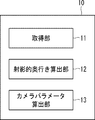
- FIG. 1 is a block diagram showing an example of a camera calibration device according to the first embodiment.
- the camera calibration device 10 includes an acquisition unit 11, a projective depth calculation unit 12, and a camera parameter calculation unit 13.
- the acquisition unit 11 acquires a plurality of "normal lines in the image plane” in the “image plane” of the image in which the "world coordinate space” is taken by the camera (not shown).
- Each of the plurality of "image plane normal vectors” corresponds to a plurality of "world coordinate space normal vectors” with respect to the "reference plane” in the "world coordinate space”.
- the "world coordinate space” is a space defined by the world coordinate system.
- the "reference plane” may be a horizontal plane such as the ground or the floor. Further, the "normal vector in the world coordinate space” may be, for example, an edge of a building or a shelf extending perpendicular to the above horizontal plane.
- the plurality of "image plane normal vectors" acquired by the acquisition unit 11 have two image plane normal vectors corresponding to two world coordinate space normal vectors having the same length. Including.
- two world coordinate space normal vectors having the same length may be referred to as a "first world coordinate space normal vector” and a “second world coordinate space normal vector”.
- the two image plane normal vectors corresponding to the "first world coordinate space normal vector” and the “second world coordinate space normal vector” are referred to as the "first image plane normal vector” and It may be called "second image plane normal vector”.
- the projective depth calculation unit 12 uses four "projective depths" corresponding to the start point and end point of the first image plane normal vector and the start point and end point of the second image plane normal vector as vector elements. Calculate the "projective depth vector".
- the start point and the end point of the normal vector in the first image plane may be referred to as a "first start point” and a “first end point”.
- the start point and the end point of the normal vector in the second image plane may be referred to as a "second start point” and a "second end point”.
- the projective depth calculation unit 12 calculates the projective depth with respect to the three-dimensional coordinates of the first starting point from the camera. Similarly, the projective depth is calculated for the first end point, the second start point, and the second end point. That is, the "projective depth” means the depth to the three-dimensional coordinates seen from the camera in the projective space.
- the projection depth vector is a matrix of the start point vector in the first image plane, the end point vector in the first image plane, the start point vector in the second image plane, and the end point vector in the second image plane.
- the projection depth vector is calculated based on the relationship, which is the "zero space" of the "first matrix" as an element.
- the camera parameter calculation unit 13 calculates the internal parameters and external parameters of the camera. This calculation includes the projection depth vector calculated by the projection depth calculation unit 12, the "first image plane start point vector”, the “first image plane end point vector”, and the “second image plane start point vector”. , And the "second image plane end point vector”.
- the "first image plane start point vector” and the “first image plane end point vector” correspond to the first start point and the first end point, respectively, and the “second image plane start point vector” and the “second image plane end point vector” correspond to each other.
- the “vector” corresponds to the second start point and the second end point, respectively.
- the acquisition unit 11 is in the first world coordinate space, each of which is a normal vector with respect to the reference plane in the world coordinate space and has the same length as each other.
- the first image plane normal vector and the second image plane normal vector corresponding to the normal vector and the second world coordinate space normal vector are acquired.
- the projective depth calculation unit 12 has four projective depths corresponding to the start point and end point of the first image in-plane normal vector and the start point and end point of the second image in-plane normal vector as vector elements. Calculate the vector.
- the internal parameters and the external parameters can be calculated without using the calibration board. That is, the internal parameter and the external parameter can be calculated by a simpler method.
- the second embodiment relates to a more specific embodiment.
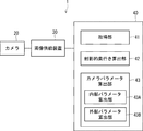
- FIG. 2 is a block diagram showing an example of the camera system according to the second embodiment.
- the camera system 1 includes a camera 20, an image supply device 30, and a camera calibration device 40.
- the camera 20 captures an image target area in the "world coordinate system” to form an image P1.
- FIG. 3 is a diagram used to explain the relationship between the camera coordinate system and the world coordinate system.
- the origin of the world coordinate system coincides with the start point (M 1 ) of the normal vector in the first world coordinate space.
- the first global coordinate space normal vector end point (M '1) is located on the z-axis of the world coordinate system.
- the starting point (M 2 ) of the normal vector in the second world coordinate space is located on the x-axis of the world coordinate system. That is, the straight line connecting the start point (M 1 ) of the normal vector in the first world coordinate space and the start point (M 2 ) of the normal vector in the second world coordinate space coincides with the x-axis of the world coordinate system.
- the direction orthogonal to both the x-axis and the z-axis is defined as the y-axis.
- the above “reference plane” coincides with the xy plane of the world coordinate system. Since lengths of the first world coordinate space normal vector and the second world coordinate space normal vector are the same, the first world coordinate space normal vector end point (M '1) and a second global coordinate z coordinate of the end point of the space normal vector (M '2) are both in the "z".
- the three-dimensional coordinates of the world coordinate system are not explicitly given, so that the world coordinate system and the camera coordinate system may be arbitrarily defined as long as they are relatively equivalent. Therefore, as shown in FIG. 3, even if the world coordinate system and the camera coordinate system are set, the generality is not lost.
- R represents a rotation vector
- t represents a translation vector. That is, the position and orientation of the camera 20 with respect to the world coordinates are represented by the rotation matrix R and the translation vector t.
- the image supply device 30 acquires the image formed by the camera 20 and supplies the acquired image to the camera calibration device 40.
- the image supply device 30 may transmit the acquired image to the camera calibration device 40 via a communication unit (not shown).
- the image may be a single still image at a certain time, each frame image of a continuous moving image in a time series, or a plurality of still images having different time series.
- the camera calibration device 40 includes an acquisition unit 41, a projective depth calculation unit 42, and a camera parameter calculation unit 43.
- the camera parameter calculation unit 43 has an internal parameter calculation unit 43A and an external parameter calculation unit 43B.
- the acquisition unit 41 acquires a plurality of "image plane normal vectors" in the "image plane” of the image supplied from the image supply device 30.
- the acquisition unit 41 may automatically acquire a line segment of an artificial object such as a building or a box that intersects or touches the ground perpendicularly in the image supplied from the image supply device 30 by image processing. ..
- the acquisition unit 41 may automatically acquire the spine joint in each frame image as a normal vector by combining tracking of a specific person in the moving image supplied from the image supply device 30 and joint detection.
- the acquisition unit 41 may accept the designation of the "image plane normal vector" by the user manually for the image supplied from the image supply device 30.
- the plurality of "normals in the image plane" acquired by the acquisition unit 41 are the “first world coordinate space normal vectors” and the “first world coordinate space normal vectors” having the same length. It includes a “first image plane normal vector” and a “second image plane normal vector” corresponding to the "two world coordinate space normal vectors", respectively.
- the projective depth calculation unit 42 like the projective depth calculation unit 12 of the first embodiment, has the first start point and the first end point of the first image plane normal vector and the second image plane normal vector.
- a "projective depth vector” is calculated with four “projective depths” corresponding to the two start points and the second end points as vector elements. The calculation of the "projective depth vector” will be described in detail later.
- the internal parameter calculation unit 43A includes a projection depth vector calculated by the projection depth calculation unit 42, a start point vector in the first image plane, an end point vector in the first image plane, a start point vector in the second image plane, and a first. 2
- the focal distance f of the camera 20 is calculated based on the end point vector in the image plane.
- the focal length f of the camera 20 is one of the internal parameters. In the calculation of the focal length f, for example, an orthogonal relationship between each of the two column vectors of the rotation matrix R is used. The calculation of internal parameters will be described in detail later.
- the external parameter calculation unit 43B includes a projection depth vector calculated by the projection depth calculation unit 42, a start point vector in the first image plane, an end point vector in the first image plane, a start point vector in the second image plane, and a first. 2
- the rotation matrix R and the translation vector t are calculated based on the end point vector in the image plane and the focal distance f calculated by the internal parameter calculation unit 43A. The calculation of external parameters will be described in detail later.
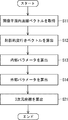
- FIG. 4 is a flowchart showing an example of the processing operation of the camera calibration device according to the second embodiment.
- the acquisition unit 41 acquires the first image plane normal vector and the second image plane normal vector from the image taken by the camera 20 (step S11).
- the projective depth calculation unit 42 has four “projective” values corresponding to the first start point and the first end point of the first image plane normal vector and the second start point and the second end point of the second image plane normal vector, respectively.
- a "projective depth vector” with "depth” as a vector element is calculated (step S12).
- the internal parameter calculation unit 43A includes the projection depth vector calculated in step S12, the start point vector in the first image plane, the end point vector in the first image plane, the start point vector in the second image plane, and the start point vector in the second image plane.
- the focal distance f of the camera 20 is calculated based on the end point vector (step S13).
- the external parameter calculation unit 43B includes the projection depth vector calculated by the projection depth calculation unit 42 in step S12, the start point vector in the first image plane, the end point vector in the first image plane, and the start point in the second image plane.
- the rotation matrix R and the translation vector t are calculated based on the vector, the end point vector in the second image plane, and the focal distance f calculated in step S13 (step S14).
- the unknown internal parameter is the focal length f.
- the start point and end point of the normal vector in the i-th world coordinate space can be projected from the three-dimensional space to the image coordinates by using the equation (1).
- lambda i represents the projective depth of the start point of the i-th image plane normal vector
- lambda 'i represents the projective depth of the end point of the i-th image plane normal vector
- K represents an internal parameter matrix.
- equation (1) When equation (1) is written down for the first image plane normal vector, the second image plane normal vector, the first world coordinate space normal vector, and the second world coordinate space normal vector, the formula (1) is written down. It can be expressed as (2).
- r j represents the j-th column vector in the rotation matrix R.
- the formula (3) is obtained by taking the difference between the first formula and the second formula in the formula (2) and taking the difference between the third formula and the fourth formula.
- the equation (4) is obtained by taking the difference between the first equation and the second equation.
- Equation (4) shows that the projective depth is the zero space of the 3 ⁇ 4 matrix A.
- projective depth vector [ ⁇ 1, ⁇ '1, ⁇ 2, ⁇ ' 2] T the first image plane origin vector m 1, the end point vector m '1 first image plane, a second image It is a zero space of the matrix A having the start point vector m 2 in the plane and the end point vector m ' 2 in the second image plane as matrix elements. That is, the ratio of each projective depth can be obtained excluding the scale indefiniteness. Although there is indefiniteness of the sign, since the sign of the projective depth based on the equation (1) is positive, it is sufficient to select so that the sign of all ⁇ is positive.
- Equation (6) is a quadratic equation for f, but a solution with a positive sign may be obtained. In this way, the internal parameters can be calculated.
- the height z of the first world coordinate space normal vector and the second world coordinate space normal vector, and the x-axis coordinate x 2 of the second world coordinate space normal vector are the definitions of the world coordinate system. Therefore, the sign is positive. Therefore, the rotation matrix R can be expressed by the equation (8).
- the translation vector t can be expressed by the equation (9) using the first equation of the equation (2).
- the acquisition unit 41 is within the first world coordinate space, each of which is a normal vector with respect to the reference plane in the world coordinate space and has the same length as each other.
- the first image plane normal vector and the second image plane normal vector corresponding to the normal vector and the second world coordinate space normal vector are acquired.
- the projective depth calculation unit 42 has four projective depths corresponding to the start point and end point of the first image in-plane normal vector and the start point and end point of the second image in-plane normal vector as vector elements. Calculate the vector.
- the projective depth vector can be calculated by the configuration of the camera calibration device 40, the internal parameters and the external parameters can be calculated without using the calibration board. That is, the internal parameter and the external parameter can be calculated by a simpler method. Further, it is possible to calibrate the monocular camera by using only the image information under the condition that the three-dimensional coordinates are unknown. The reason is as follows. First, the equation (2), the number of unknowns is the 13 ( ⁇ 1, ⁇ '1, ⁇ 2, ⁇ ' 2, x 2, z, f, t, 3 -axis rotation angle of the rotation matrix R) .. However, between the projective depth and three-dimensional coordinates x 2, z for ambiguity scale is present, the actual degree of freedom is 12.
- the camera system 1 in the second embodiment can be modified as follows.
- the settings of the world coordinate system and the camera coordinate system are not limited to the above settings.
- the reference plane is not limited to the horizontal plane.
- a line segment parallel to the floor surface may be defined as a normal vector in the world coordinate space with the wall surface as a reference plane.
- the first world coordinate space normal vector and the second world coordinate space are based on the first image plane normal vector and the second image plane normal vector, and the internal parameter and the external parameter.
- the three-dimensional coordinates of the start point and end point of each of the inner normal vectors are calculated. Since the basic configuration of the camera system in the third embodiment is the same as that of the camera system 1 in the second embodiment, it will be described with reference to FIG. That is, the camera system 1 in the third embodiment includes the camera calibration device 50 shown in FIG. 5 instead of the camera calibration device 40.
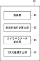
- FIG. 5 is a block diagram showing an example of the camera calibration device according to the third embodiment.
- the camera calibration device 50 has a three-dimensional coordinate calculation unit 51.
- the three-dimensional coordinate calculation unit 51 includes the first image plane normal vector and the second image plane normal vector acquired by the acquisition unit 41, and the internal and external parameters calculated by the camera parameter calculation unit 43. Based on the above, two three-dimensional coordinates in the world coordinate system are calculated for the start point coordinates and the end point coordinates of each image plane normal vector. That is, the three-dimensional coordinate calculation unit 51 includes the first image plane normal vector and the second image plane normal vector acquired by the acquisition unit 41, the internal parameters calculated by the camera parameter calculation unit 43, and the internal parameters. Based on the external parameters, the three-dimensional coordinates of the start point and end point of the first world coordinate space normal vector and the second world coordinate space normal vector are calculated.
- Equation (10) is an equation for obtaining three-dimensional coordinates when the length of the normal vector in the first world coordinate space and the length of the normal vector in the second world coordinate space are the same.
- equation (11) is an equation for obtaining three-dimensional coordinates when the length of the normal vector in the first world coordinate space and the length of the normal vector in the second world coordinate space are different.
- the modification of the equation (1) here utilizes the fact that the cross product of these is zero because the vectors of both sides of the first equation of the equation (1) are equal. The same applies to the second equation of the equation (1).
- the vectors r 1 , r 2 , and r 3 represent the column vectors of the rotation matrix R, respectively, and [xi i , y i ] and [xi i , y i , z i ] are the three-dimensional coordinates of the calculation target. Represents. In the case of the formula (10), z i is z.
- equations (10) and (11) are linear simultaneous equations, they can be easily solved.
- FIG. 6 is a flowchart showing an example of the processing operation of the camera calibration device according to the third embodiment.
- steps S11 to S14 are the same as the flowchart of FIG.
- the three-dimensional coordinate calculation unit 51 uses the first image in-plane normal vector and the second image in-plane normal vector acquired in step S11, and the internal and external parameters calculated in steps S13 and S14. Based on this, the three-dimensional coordinates of the start point and the end point of the first world coordinate space normal vector and the second world coordinate space normal vector are calculated (step S21).
- the camera system 1 in the third embodiment can be modified as follows.
- the formulas for calculating the three-dimensional coordinates of the start point and the end point of the first world coordinate space normal vector and the second world coordinate space normal vector are the formulas (10) and (11). It is not limited.
- the three-dimensional coordinates may be calculated including the projective depth that has been erased.
- the three-dimensional coordinate calculation unit 51 is a world coordinate space corresponding to at least one of a plurality of image plane normal vectors in addition to the plurality of image plane normal vectors, internal parameters, and external parameters.
- Absolute three-dimensional coordinates may be calculated based on the length of the internal normal vector or the coordinates on the z-axis of the origin of the camera coordinate system. That is, if the absolute length (for example, in meters) of the world coordinate space normal vector corresponding to at least one of the acquired multiple image plane normal vectors is known, it is used. Then, the relative relationship of the camera position and the three-dimensional coordinates of the normal vector in the world coordinate space can be converted into an absolute relationship.
- the fourth embodiment relates to the optimization process of the internal parameters, the external parameters, and the two three-dimensional coordinates for each image plane normal vector calculated by the three-dimensional coordinate calculation unit. Since the basic configuration of the camera system is the same as that of the camera system 1 in the second embodiment, it will be described with reference to FIG. That is, the camera system 1 in the fourth embodiment includes the camera calibration device 60 shown in FIG. 7 instead of the camera calibration device 40.
- FIG. 7 is a block diagram showing an example of the camera calibration device according to the fourth embodiment.
- the camera calibration device 60 has an optimization unit 61.
- the optimization unit 61 executes "optimization processing" of the internal parameters, the external parameters, and the two three-dimensional coordinates for each image plane normal vector calculated by the three-dimensional coordinate calculation unit 51. For example, the optimization unit 61 internally calculates the three-dimensional coordinates of the start point and the end point of the first world coordinate space normal vector and the second world coordinate space normal vector by the camera parameter calculation unit 43. Two "reprojection coordinates" projected onto the image plane are calculated using the parameters and external parameters. Then, the optimization unit 61 includes two "reprojection coordinates" of the first world coordinate space normal vector and the second world coordinate space normal vector, and the first image plane normal vector and the second.
- the adjusted internal parameters, the adjusted external parameters, and the adjusted 2 above are expected to minimize the "reprojection error", which is the error between the start and end points of the normal vector in the image plane. Find two three-dimensional coordinates. Thereby, the internal parameters and external parameters of the camera 20 and the above-mentioned three-dimensional coordinates can be optimized.
- the optimization unit 61 uses the three-dimensional coordinates calculated by the three-dimensional coordinate calculation unit 51 and the internal parameters and external parameters calculated by the camera parameter calculation unit 43 as initial values based on the equation (12). May be used to perform non-linear optimization.
- the optimization unit 61 may optimize each parameter by solving the equation (12) using, for example, a known method such as the Rube Marquard method or the trust region method.
- the optimization unit 61 may use at least one of the focal length, skew, optical center, and lens distortion of the camera 20 as internal parameters to be optimized.
- Proj represents a function that divides each of the first component and the second component by the third component of the three-dimensional vector and converts them into a homogeneous coordinate system.
- the constraint condition for the three-dimensional coordinates of equation (12) is for removing relative indefiniteness.
- equations (4) and (7) to (9) are based on linear simultaneous equations that minimize so-called algebraic errors.
- errors may accumulate in the later stages. Therefore, by minimizing the so-called reprojection error as represented by the equation (12), the error between the parameters can be homogenized and the statistically optimum parameter can be calculated.
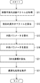
- FIG. 8 is a flowchart showing an example of the processing operation of the camera calibration device according to the fourth embodiment.
- the optimization unit 61 "optimizes processing" of the internal parameters and external parameters calculated in steps S13 and S14 and the two three-dimensional coordinates of each image plane normal vector calculated in step S21. Is executed (step S31).
- the camera system 1 in the fourth embodiment can be modified as follows.
- the lens distortion may be included in the parameter to be optimized in the equation (12). That is, even when the normal in the image plane becomes a curve on the image due to the lens distortion, the normal vector in the image plane at the center of the image where the lens distortion is small is used or the lens distortion is minute.
- the final solution can be obtained by including the lens distortion as an unknown in the calculation of the equation (12) after performing the processing up to step S21 on the assumption.
- the optimization unit 61 can obtain the lens distortion.
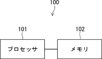
- FIG. 9 is a diagram showing a hardware configuration example of the camera calibration device.
- the camera calibration device 100 has a processor 101 and a memory 102.
- the processor 101 may be, for example, a microprocessor, an MPU (Micro Processing Unit), or a CPU (Central Processing Unit).
- the processor 101 may include a plurality of processors.
- the memory 102 is composed of a combination of a volatile memory and a non-volatile memory.
- the memory 102 may include storage located away from the processor 101. In this case, the processor 101 may access the memory 102 via an I / O interface (not shown).
- the camera calibration devices 10, 40, 50, and 60 of the first to fourth embodiments can each have the hardware configuration shown in FIG. Acquiring units 11, 41 of the camera calibration devices 10, 40, 50, 60 of the first to fourth embodiments, projective depth calculation units 12, 42, camera parameter calculation units 13, 43, and three-dimensional coordinates.
- the calculation unit 51 and the optimization unit 61 may be realized by the processor 101 reading and executing the program stored in the memory 102.
- the program is stored using various types of non-transitory computer readable medium and can be supplied to the camera calibration devices 10, 40, 50, 60. Examples of non-temporary computer-readable media include magnetic recording media (eg, flexible disks, magnetic tapes, hard disk drives), magneto-optical recording media (eg, magneto-optical disks).
- non-temporary computer-readable media include CD-ROM (Read Only Memory), CD-R, and CD-R / W.
- non-transitory computer-readable media include semiconductor memory.
- the semiconductor memory includes, for example, a mask ROM, a PROM (Programmable ROM), an EPROM (Erasable PROM), a flash ROM, and a RAM (Random Access Memory).
- the program may also be supplied to the camera calibrators 10, 40, 50, 60 by various types of temporary computer readable media. Examples of temporary computer-readable media include electrical, optical, and electromagnetic waves.
- the temporary computer-readable medium can supply the program to the camera calibration devices 10, 40, 50, 60 via a wired communication path such as an electric wire and an optical fiber, or a wireless communication path.
- Projective depth calculation unit that calculates the target depth vector, Corresponds to the calculated projection depth vector, the first image plane start point vector and the first image plane end point vector corresponding to the first start point and the first end point, respectively, and the second start point and the second end point, respectively.
- a camera parameter calculation unit that calculates the internal and external parameters of the camera based on the start point vector in the second image plane and the end point vector in the second image plane.
- the projection depth vector is the start point vector in the first image plane, the end point vector in the first image plane, the start point vector in the second image plane, and the end point in the second image plane.
- the projection depth vector is calculated based on the relationship, which is the zero space of the first matrix whose matrix element is a vector.
- the external parameters include a rotation matrix and a translation vector.
- the camera parameter calculation unit includes the calculated projection depth vector, the first image plane start point vector, the first image plane end point vector, the second image plane start point vector, and the second image plane. It includes an internal parameter calculation unit that calculates the focal distance of the camera as the internal parameter based on the internal end point vector and the orthogonal relationship between each of the two column vectors of the rotation matrix.
- the camera calibration device according to Appendix 1 or 2.
- the camera parameter calculation unit includes the calculated projection depth vector, the first image plane start point vector, the first image plane end point vector, the second image plane start point vector, and the second image plane. It further includes an external parameter calculation unit that calculates the rotation matrix and the translation vector based on the internal end point vector and the calculated focal distance.
- the camera calibration device according to Appendix 3.
- the internal parameter calculation unit calculates the focal length of the camera using the equation (A1).
- the camera calibration device according to Appendix 5.
- ⁇ 1 , ⁇ ′ 1 , ⁇ 2 and ⁇ ′ 2 represent the projection depths of the first start point, the first end point, the second start point, and the second end point, respectively
- f is wherein represents a focal length, vector n 1, n '1, n 2, n' 2 , respectively, wherein the first image plane starting vector, said first image plane end point vector, wherein the second image plane origin vector , And the end point vector in the second image plane.
- the external parameter calculation unit calculates the rotation matrix using the equations (A2), (A3), and (A4), and uses the equations (A4) and (A5) to calculate the translation vector. calculate,
- the camera calibration device 6
- R represents the rotation matrix vector r 1
- r 3 represents a first column and third row of the column vector of the rotation matrix
- z is the first global coordinate space normal vector Represents the coordinates of the third axis of the end point and the end point of the normal vector in the second world coordinate space
- x 2 represents the coordinates of the start point of the normal vector in the second world coordinate space on the first axis.
- lambda 1, lambda '1, lambda 2, and lambda' 2 each represent the first starting point, the first end point, the second starting point, and projective depth of the second end point vector m 1, m '1, m 2, m' 2, respectively, wherein the first image plane starting vector, said first image plane end point vector, the second image plane starting vector, and the second image plane end point vector Represents. // // represents the L2 norm.
- t represents the translation vector.
- K represents the internal parameter matrix
- f represents the focal length.
- Appendix 8 The first world based on the first image plane normal vector and the second image plane normal vector acquired by the acquisition unit, and the internal and external parameters calculated by the camera parameter calculation unit.
- a three-dimensional coordinate calculation unit for calculating the three-dimensional coordinates of the start point and the end point of the normal in the coordinate space vector and the normal vector in the second world coordinate space is further provided.
- the camera calibration device according to any one of Appendix 5 to 7.
- the three-dimensional coordinate calculation unit calculates the three-dimensional coordinates using the equation (A6).
- the camera calibration device 8
- the vector r 1, r 2, r 3, respectively, represents the column vector of the rotation matrix
- X i , y i represent the coordinates of the first axis and the second axis of the world coordinate system of the start point and the end point of the normal vector in the i-th world coordinate space
- z is the method in the first world coordinate space.
- t represents the translation vector.
- K represents the internal parameter matrix represented by the equation (A7), and f represents the focal length.
- the three-dimensional coordinates of the start point and the end point of the calculated normal line vector in the first world coordinate space and the normal line vector in the second world coordinate space are the internal parameters and the outside calculated by the camera parameter calculation unit.
- the reprojection error which is the error between the two reprojection coordinates projected onto the image plane using the parameters and the start and end points of the first image plane normal vector and the second image plane normal vector, respectively.
- the internal parameters and external parameters of the camera and the three-dimensional coordinates are optimized by obtaining the adjusted internal parameters, the adjusted external parameters, and the adjusted three-dimensional coordinates, which are expected to minimize the above.
- the camera calibration device according to Appendix 8 or 9.
- the optimization unit uses the three-dimensional coordinates calculated by the three-dimensional coordinate calculation unit and the internal parameters and external parameters calculated by the camera parameter calculation unit as initial values.
- the internal and external parameters of the camera and the three-dimensional coordinates are optimized by performing non-linear optimization.
- Proj represents a function that divides each of the first component and the second component by the third component of the three-dimensional vector and converts them into a synchronous coordinate system
- R represents the rotation matrix
- t the rotation matrix
- the optimization unit sets at least one of the focal length, skew, optical center, and lens distortion of the camera as an internal parameter to be optimized.
- the camera calibration device according to Appendix 10 or 11.
- Appendix 13 The camera calibration device according to any one of Appendix 1 to 12 and An image supply device that supplies an image of the world coordinate space captured by the camera to the camera calibration device, A camera system equipped with.
- Calculate the target depth vector Corresponds to the calculated projection depth vector, the first image plane start point vector and the first image plane end point vector corresponding to the first start point and the first end point, respectively, and the second start point and the second end point, respectively.
- the internal and external parameters of the camera are calculated based on the start point vector in the second image plane and the end point vector in the second image plane. Camera calibration method.
- Calculate the target depth vector Corresponds to the calculated projection depth vector, the first image plane start point vector and the first image plane end point vector corresponding to the first start point and the first end point, respectively, and the second start point and the second end point, respectively.
- the internal and external parameters of the camera are calculated based on the start point vector in the second image plane and the end point vector in the second image plane.
- a non-transitory computer-readable medium containing a program that causes a camera calibrator to perform processing.
Landscapes
- Engineering & Computer Science (AREA)
- Physics & Mathematics (AREA)
- General Physics & Mathematics (AREA)
- Computer Vision & Pattern Recognition (AREA)
- Theoretical Computer Science (AREA)
- Biomedical Technology (AREA)
- Health & Medical Sciences (AREA)
- General Health & Medical Sciences (AREA)
- Multimedia (AREA)
- Signal Processing (AREA)
- Studio Devices (AREA)
- Length Measuring Devices By Optical Means (AREA)
- Image Processing (AREA)
Abstract
L'invention concerne un dispositif d'étalonnage de caméra (10) dans lequel une unité d'acquisition (11) acquiert un premier vecteur normal de plan d'image intra et un second vecteur normal de plan d'image intra correspondant respectivement à un premier vecteur normal d'espace de coordonnée universelle intra et un second vecteur normal d'espace de coordonnée universelle intra constituant des vecteurs normaux à un plan de référence dans un espace de coordonnée universelle et ayant la même longueur. Une unité de calcul de profondeur de projection (12) calcule un vecteur de profondeur de projection ayant, en tant qu'éléments de vecteur, quatre profondeurs de projection correspondant respectivement au point de départ et au point d'arrivée du premier vecteur normal de plan d'image intra et du point de départ et du point d'arrivée du second vecteur normal de plan d'image intra.
Priority Applications (4)
| Application Number | Priority Date | Filing Date | Title |
|---|---|---|---|
| JP2021513046A JP7151879B2 (ja) | 2019-04-08 | 2019-04-08 | カメラ校正装置、カメラ校正方法、及びプログラム |
| US17/600,716 US11830223B2 (en) | 2019-04-08 | 2019-04-08 | Camera calibration apparatus, camera calibration method, and nontransitory computer readable medium storing program |
| PCT/JP2019/015330 WO2020208686A1 (fr) | 2019-04-08 | 2019-04-08 | Dispositif et procédé d'étalonnage de caméra et support non transitoire lisible par ordinateur sur lequel est mémorisé un programme associé |
| US17/687,990 US11521333B2 (en) | 2019-04-08 | 2022-03-07 | Camera calibration apparatus, camera calibration method, and non-transitory computer readable medium storing program |
Applications Claiming Priority (1)
| Application Number | Priority Date | Filing Date | Title |
|---|---|---|---|
| PCT/JP2019/015330 WO2020208686A1 (fr) | 2019-04-08 | 2019-04-08 | Dispositif et procédé d'étalonnage de caméra et support non transitoire lisible par ordinateur sur lequel est mémorisé un programme associé |
Related Child Applications (2)
| Application Number | Title | Priority Date | Filing Date |
|---|---|---|---|
| US17/600,716 A-371-Of-International US11830223B2 (en) | 2019-04-08 | 2019-04-08 | Camera calibration apparatus, camera calibration method, and nontransitory computer readable medium storing program |
| US17/687,990 Continuation US11521333B2 (en) | 2019-04-08 | 2022-03-07 | Camera calibration apparatus, camera calibration method, and non-transitory computer readable medium storing program |
Publications (1)
| Publication Number | Publication Date |
|---|---|
| WO2020208686A1 true WO2020208686A1 (fr) | 2020-10-15 |
Family
ID=72751184
Family Applications (1)
| Application Number | Title | Priority Date | Filing Date |
|---|---|---|---|
| PCT/JP2019/015330 WO2020208686A1 (fr) | 2019-04-08 | 2019-04-08 | Dispositif et procédé d'étalonnage de caméra et support non transitoire lisible par ordinateur sur lequel est mémorisé un programme associé |
Country Status (3)
| Country | Link |
|---|---|
| US (2) | US11830223B2 (fr) |
| JP (1) | JP7151879B2 (fr) |
| WO (1) | WO2020208686A1 (fr) |
Cited By (2)
| Publication number | Priority date | Publication date | Assignee | Title |
|---|---|---|---|---|
| CN113223095A (zh) * | 2021-05-25 | 2021-08-06 | 中国人民解放军63660部队 | 一种基于已知相机位置内外参数标定方法 |
| CN113781575A (zh) * | 2021-08-09 | 2021-12-10 | 上海奥视达智能科技有限公司 | 一种相机参数的标定方法、装置、终端和存储介质 |
Families Citing this family (3)
| Publication number | Priority date | Publication date | Assignee | Title |
|---|---|---|---|---|
| WO2020208686A1 (fr) * | 2019-04-08 | 2020-10-15 | 日本電気株式会社 | Dispositif et procédé d'étalonnage de caméra et support non transitoire lisible par ordinateur sur lequel est mémorisé un programme associé |
| US11610338B2 (en) * | 2021-03-26 | 2023-03-21 | Fotonation Limited | Method of controlling a camera |
| CN115170434A (zh) * | 2022-07-28 | 2022-10-11 | 江苏集萃智能光电系统研究所有限公司 | 一种用于线结构光3d相机的误差校正方法以及装置 |
Citations (5)
| Publication number | Priority date | Publication date | Assignee | Title |
|---|---|---|---|---|
| US20020186897A1 (en) * | 2001-04-02 | 2002-12-12 | Korea Advanced Institute Of Science And Technology | Camera calibration system using planar concentric circles and method thereof |
| JP2005352630A (ja) * | 2004-06-09 | 2005-12-22 | Pulstec Industrial Co Ltd | 座標変換係数取得方法、座標変換係数取得装置およびコンピュータプログラム |
| JP2007256091A (ja) * | 2006-03-23 | 2007-10-04 | Space Vision:Kk | レンジファインダ校正方法及び装置 |
| JP2010181919A (ja) * | 2009-02-03 | 2010-08-19 | Toyohashi Univ Of Technology | 三次元形状特定装置、三次元形状特定方法、三次元形状特定プログラム |
| WO2013111229A1 (fr) * | 2012-01-23 | 2013-08-01 | 日本電気株式会社 | Dispositif, procédé et programme d'étalonnage d'un appareil de prise de vues |
Family Cites Families (29)
| Publication number | Priority date | Publication date | Assignee | Title |
|---|---|---|---|---|
| CA2765489C (fr) | 2009-06-23 | 2017-11-28 | Teruaki Iyori | Coupelle de cornue |
| ES2399636T3 (es) * | 2009-07-29 | 2013-04-02 | Metaio Gmbh | Método para determinar la postura de una cámara con respecto a por lo menos un objeto real |
| JP5680353B2 (ja) * | 2010-08-24 | 2015-03-04 | 富士フイルム株式会社 | 水性インク組成物、インクジェット記録方法及びインクジェット印画物 |
| US8995754B2 (en) * | 2013-05-30 | 2015-03-31 | Xerox Corporation | Estimating a pose of a camera for volume estimation |
| JP6261016B2 (ja) | 2013-09-30 | 2018-01-17 | 国立研究開発法人産業技術総合研究所 | マーカ画像処理システム |
| WO2016042779A1 (fr) | 2014-09-18 | 2016-03-24 | 日本電気株式会社 | Dispositif de triangulation, procédé de triangulation, et programme d'enregistrement de support d'enregistrement associé |
| WO2016076400A1 (fr) * | 2014-11-13 | 2016-05-19 | オリンパス株式会社 | Dispositif d'étalonnage, procédé d'étalonnage, dispositif optique, dispositif d'imagerie, dispositif de projection, système de mesure, et procédé de mesure |
| JP6464934B2 (ja) * | 2015-06-11 | 2019-02-06 | 富士通株式会社 | カメラ姿勢推定装置、カメラ姿勢推定方法およびカメラ姿勢推定プログラム |
| US10602126B2 (en) * | 2016-06-10 | 2020-03-24 | Lucid VR, Inc. | Digital camera device for 3D imaging |
| JP6735615B2 (ja) * | 2016-06-29 | 2020-08-05 | キヤノン株式会社 | 情報処理装置、情報処理装置の制御方法およびプログラム |
| CN106403845B (zh) * | 2016-09-14 | 2017-10-03 | 杭州思看科技有限公司 | 三维传感器系统及三维数据获取方法 |
| KR102576842B1 (ko) * | 2017-01-04 | 2023-09-12 | 삼성전자주식회사 | 핸드-아이 캘리브레이션을 수행하는 로봇 및 전자 장치 |
| JP7052788B2 (ja) | 2017-03-14 | 2022-04-12 | 日本電気株式会社 | カメラパラメータ推定装置、カメラパラメータ推定方法、及びプログラム |
| CN109242779B (zh) * | 2018-07-25 | 2023-07-18 | 北京中科慧眼科技有限公司 | 一种相机成像模型的构建方法、装置及汽车自动驾驶系统 |
| US10552983B1 (en) * | 2018-08-23 | 2020-02-04 | Qualcomm Incorporated | Camera calibration |
| CN109754432B (zh) | 2018-12-27 | 2020-09-22 | 深圳市瑞立视多媒体科技有限公司 | 一种相机自动标定方法及光学动作捕捉系统 |
| US11758110B2 (en) | 2019-02-28 | 2023-09-12 | Nec Corporation | Camera calibration information acquisition device, image processing device, camera calibration information acquisition method, and recording medium |
| WO2020188799A1 (fr) * | 2019-03-20 | 2020-09-24 | 日本電気株式会社 | Dispositif et procédé d'étalonnage de caméra, et support non transitoire lisible par ordinateur sur lequel est stocké un programme associé |
| US20220156977A1 (en) | 2019-03-26 | 2022-05-19 | Nec Corporation | Calibration apparatus, calibration method, and non-transitory computer readable medium storing program |
| TWI720447B (zh) * | 2019-03-28 | 2021-03-01 | 財團法人工業技術研究院 | 影像定位方法及其系統 |
| WO2020208686A1 (fr) * | 2019-04-08 | 2020-10-15 | 日本電気株式会社 | Dispositif et procédé d'étalonnage de caméra et support non transitoire lisible par ordinateur sur lequel est mémorisé un programme associé |
| US11935266B2 (en) * | 2019-04-24 | 2024-03-19 | Nec Corporation | Camera parameter estimation apparatus, camera parameter estimation method, and computer-readable recording medium |
| US11257272B2 (en) | 2019-04-25 | 2022-02-22 | Lucid VR, Inc. | Generating synthetic image data for machine learning |
| CN110327046B (zh) | 2019-04-28 | 2022-03-25 | 安翰科技(武汉)股份有限公司 | 一种基于摄像系统的消化道内物体测量方法 |
| CN110232716A (zh) * | 2019-05-31 | 2019-09-13 | 深圳市道通智能航空技术有限公司 | 一种相机标定方法、装置和电子设备 |
| WO2021020062A1 (fr) * | 2019-07-30 | 2021-02-04 | パナソニックIpマネジメント株式会社 | Procédé et dispositif de mesure de déplacement tridimensionnel |
| KR20220026422A (ko) * | 2020-08-25 | 2022-03-04 | 삼성전자주식회사 | 카메라 캘리브레이션 장치 및 이의 동작 방법 |
| KR20220153802A (ko) * | 2021-05-12 | 2022-11-21 | 삼성전자주식회사 | 캘리브레이션 방법 및 장치 |
| US20230080638A1 (en) * | 2021-09-13 | 2023-03-16 | Toyota Research Institute, Inc. | Systems and methods for self-supervised learning of camera intrinsic parameters from a sequence of images |
-
2019
- 2019-04-08 WO PCT/JP2019/015330 patent/WO2020208686A1/fr active Application Filing
- 2019-04-08 US US17/600,716 patent/US11830223B2/en active Active
- 2019-04-08 JP JP2021513046A patent/JP7151879B2/ja active Active
-
2022
- 2022-03-07 US US17/687,990 patent/US11521333B2/en active Active
Patent Citations (5)
| Publication number | Priority date | Publication date | Assignee | Title |
|---|---|---|---|---|
| US20020186897A1 (en) * | 2001-04-02 | 2002-12-12 | Korea Advanced Institute Of Science And Technology | Camera calibration system using planar concentric circles and method thereof |
| JP2005352630A (ja) * | 2004-06-09 | 2005-12-22 | Pulstec Industrial Co Ltd | 座標変換係数取得方法、座標変換係数取得装置およびコンピュータプログラム |
| JP2007256091A (ja) * | 2006-03-23 | 2007-10-04 | Space Vision:Kk | レンジファインダ校正方法及び装置 |
| JP2010181919A (ja) * | 2009-02-03 | 2010-08-19 | Toyohashi Univ Of Technology | 三次元形状特定装置、三次元形状特定方法、三次元形状特定プログラム |
| WO2013111229A1 (fr) * | 2012-01-23 | 2013-08-01 | 日本電気株式会社 | Dispositif, procédé et programme d'étalonnage d'un appareil de prise de vues |
Cited By (4)
| Publication number | Priority date | Publication date | Assignee | Title |
|---|---|---|---|---|
| CN113223095A (zh) * | 2021-05-25 | 2021-08-06 | 中国人民解放军63660部队 | 一种基于已知相机位置内外参数标定方法 |
| CN113223095B (zh) * | 2021-05-25 | 2022-06-17 | 中国人民解放军63660部队 | 一种基于已知相机位置内外参数标定方法 |
| CN113781575A (zh) * | 2021-08-09 | 2021-12-10 | 上海奥视达智能科技有限公司 | 一种相机参数的标定方法、装置、终端和存储介质 |
| CN113781575B (zh) * | 2021-08-09 | 2024-01-12 | 上海奥视达智能科技有限公司 | 一种相机参数的标定方法、装置、终端和存储介质 |
Also Published As
| Publication number | Publication date |
|---|---|
| US11521333B2 (en) | 2022-12-06 |
| US20220180563A1 (en) | 2022-06-09 |
| JP7151879B2 (ja) | 2022-10-12 |
| JPWO2020208686A1 (fr) | 2020-10-15 |
| US11830223B2 (en) | 2023-11-28 |
| US20220189066A1 (en) | 2022-06-16 |
Similar Documents
| Publication | Publication Date | Title |
|---|---|---|
| WO2020208686A1 (fr) | Dispositif et procédé d'étalonnage de caméra et support non transitoire lisible par ordinateur sur lequel est mémorisé un programme associé | |
| CN109313814B (zh) | 照相机校准系统 | |
| WO2020188799A1 (fr) | Dispositif et procédé d'étalonnage de caméra, et support non transitoire lisible par ordinateur sur lequel est stocké un programme associé | |
| US9928595B2 (en) | Devices, systems, and methods for high-resolution multi-view camera calibration | |
| JP5392415B2 (ja) | ステレオ画像生成装置、ステレオ画像生成方法及びステレオ画像生成用コンピュータプログラム | |
| JP6011548B2 (ja) | カメラ校正装置、カメラ校正方法およびカメラ校正用プログラム | |
| CN111192235B (zh) | 一种基于单目视觉模型和透视变换的图像测量方法 | |
| WO2017022033A1 (fr) | Dispositif de traitement d'images, procédé de traitement d'images et programme de traitement d'images | |
| WO2013005265A1 (fr) | Dispositif de mesure de coordonnées tridimensionnelles et procédé de mesure de coordonnées tridimensionnelles | |
| WO2018201677A1 (fr) | Procédé et dispositif d'étalonnage basé sur un réglage de faisceau pour un système d'imagerie tridimensionnelle contenant une lentille télécentrique | |
| JP2016100698A (ja) | 校正装置、校正方法、プログラム | |
| WO2023134237A1 (fr) | Procédé, appareil et système d'étalonnage de système de coordonnées pour un robot, et support | |
| JP2010186265A (ja) | カメラ校正装置、カメラ校正方法、カメラ校正プログラムおよびそのプログラムを記録した記録媒体 | |
| KR20190130407A (ko) | 전방위 카메라의 캘리브레이션을 위한 장치 및 방법 | |
| Luhmann | 3D imaging: how to achieve highest accuracy | |
| JP5235842B2 (ja) | 光学系パラメータ校正装置、光学系パラメータ校正方法、プログラム、及び記録媒体 | |
| JP2009253715A (ja) | カメラ校正装置、カメラ校正方法、カメラ校正プログラムおよびそのプログラムを記録した記録媒体 | |
| JP2021189946A (ja) | 検出装置、検出方法及び検出プログラム | |
| JP5901379B2 (ja) | 撮像装置校正方法および画像合成装置 | |
| JP2017162449A (ja) | 情報処理装置、情報処理装置の制御方法およびプログラム | |
| CN113795866A (zh) | 单视场放射影像和三维模型配准方法与系统 | |
| JP2006145419A (ja) | 画像処理方法 | |
| KR101239671B1 (ko) | 렌즈에 의한 왜곡 영상 보정방법 및 그 장치 | |
| Wong et al. | View-synthesized ‘re-calibration’of an array projector for 3D measurement from an arbitrary monocular view | |
| Liu et al. | Algorithm for camera parameter adjustment in multicamera systems |
Legal Events
| Date | Code | Title | Description |
|---|---|---|---|
| 121 | Ep: the epo has been informed by wipo that ep was designated in this application |
Ref document number: 19924214 Country of ref document: EP Kind code of ref document: A1 |
|
| ENP | Entry into the national phase |
Ref document number: 2021513046 Country of ref document: JP Kind code of ref document: A |
|
| NENP | Non-entry into the national phase |
Ref country code: DE |
|
| 122 | Ep: pct application non-entry in european phase |
Ref document number: 19924214 Country of ref document: EP Kind code of ref document: A1 |