WO2020206715A1 - 一种超重力环境下捕获高温飞断样品的缓冲装置 - Google Patents
一种超重力环境下捕获高温飞断样品的缓冲装置 Download PDFInfo
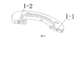
- Publication number
- WO2020206715A1 WO2020206715A1 PCT/CN2019/083492 CN2019083492W WO2020206715A1 WO 2020206715 A1 WO2020206715 A1 WO 2020206715A1 CN 2019083492 W CN2019083492 W CN 2019083492W WO 2020206715 A1 WO2020206715 A1 WO 2020206715A1
- Authority
- WO
- WIPO (PCT)
- Prior art keywords
- buffer
- support body
- hole
- groove
- upper support
- Prior art date
- Legal status (The legal status is an assumption and is not a legal conclusion. Google has not performed a legal analysis and makes no representation as to the accuracy of the status listed.)
- Ceased
Links
Images


Classifications
-
- G—PHYSICS
- G01—MEASURING; TESTING
- G01N—INVESTIGATING OR ANALYSING MATERIALS BY DETERMINING THEIR CHEMICAL OR PHYSICAL PROPERTIES
- G01N3/00—Investigating strength properties of solid materials by application of mechanical stress
- G01N3/02—Details
-
- G—PHYSICS
- G01—MEASURING; TESTING
- G01N—INVESTIGATING OR ANALYSING MATERIALS BY DETERMINING THEIR CHEMICAL OR PHYSICAL PROPERTIES
- G01N3/00—Investigating strength properties of solid materials by application of mechanical stress
- G01N3/08—Investigating strength properties of solid materials by application of mechanical stress by applying steady tensile or compressive forces
- G01N3/18—Performing tests at high or low temperatures
-
- G—PHYSICS
- G01—MEASURING; TESTING
- G01N—INVESTIGATING OR ANALYSING MATERIALS BY DETERMINING THEIR CHEMICAL OR PHYSICAL PROPERTIES
- G01N2203/00—Investigating strength properties of solid materials by application of mechanical stress
- G01N2203/003—Generation of the force
- G01N2203/0032—Generation of the force using mechanical means
- G01N2203/0037—Generation of the force using mechanical means involving a rotating movement, e.g. gearing, cam, eccentric, or centrifuge effects
Definitions
- the invention relates to the technical field of buffer devices, in particular to a buffer device suitable for capturing high-temperature flying-off samples in a supergravity environment.
- Aerospace engine turbine blades have long experienced severe load conditions such as high temperature, high pressure, and high speed during service.
- the working performance of the blade material is often a key factor that limits the performance of the whole machine.
- the real force state of the blade during service is the volume force dynamically coupled with various stresses such as centrifugal stress generated by the blade's own weight, bending stress, thermal stress, vibration stress, and shear stress generated by torque.
- the design of the blades in my country is still mainly based on the mechanical performance data of the materials under the constant gravity surface force, which seriously deviates from the real service environment of the blades in the three-dimensional volume force-temperature dynamic coupling state. Therefore, it is necessary to rely on the supergravity centrifuge provided by the supergravity centrifuge.
- the gravitational environment realizes the loading test of the applied load on the micro-defects, and the temperature field of the material is simulated through the high-temperature device to develop the dynamic failure mechanism of the material under the supergravity field.
- the buffer device used in the high gravity test device must have the characteristics of simple structure, safety and reliability, and the design must conform to the concept of high strength and light weight.
- What the present invention needs to solve is to provide a buffer device that is simple to assemble, easy to use, and has a high safety factor, and can be used in supergravity conditions for the above-mentioned problem of damage to the test device caused by high-temperature flying-off samples under the above-mentioned supergravity and high temperature test conditions .
- the invention includes an upper cover, a mechanism lever, an upper support, a locking shaft, a buffer, a lower buffer, a buffer structure, a lower partition, a lower support, an upper buffer, and a baffle;
- the bottom of the lower support is provided with an outer Flange, the outer flange at the bottom of the lower support body is fixed to the base of the test device by bolts, the bottom of the upper support body is fixed to the top of the lower support body by bolts;
- the center of the upper support body is opened with a vertical channel, and the center of the lower support body is opened with a through hole slot ,
- the buffer body is placed in the through-hole groove of the lower support body and the vertical channel of the upper support body, the bottom of the buffer body is fixed to the base of the test device by bolts;
- the upper support body is provided with upper special-shaped grooves on all sides, each upper special-shaped groove It is equipped with an actuator lever, and the side wall of the outer ring of the upper special-shaped groove is provided with a
- the actuator lever is assembled in the upper special-shaped groove opened in the upper support body; the middle of the actuator lever is provided with a lever reaming hole, and the lever reaming hole
- the sleeve is equipped with a locking shaft.
- the two ends of the locking shaft are hinged in the hinge holes of the upper special-shaped groove, so that the mechanism lever can swing around the locking shaft;
- the buffer body has a vertical through hole in the middle, and the vertical through hole of the buffer body has all four sides
- the lower special-shaped groove is opened, and the upper special-shaped groove of the upper support body and the lower special-shaped groove of the buffer body corresponding to the bottom of each mechanism lever extend into the vertical through hole space of the buffer body;
- the bottom of the vertical through hole is provided with a lower step,
- the top of the vertical through hole is provided with an upper step, the lower partition is mounted on the lower step of the buffer body, the buffer structure is mounted on the lower partition, the lower buffer layer is placed on the buffer structure, and the upper buffer layer is
- the top surface of the upper support body is provided with four grooves evenly spaced in the circumferential direction, each groove is provided with a radial guide groove in the middle, and each groove is equipped with a baffle, and the baffle faces the center
- One end of the bottom surface is provided with a baffle guide strip, the baffle guide bar is embedded in the guide groove opened on the baffle and moves along the guide groove;
- the top of the mechanism shift lever near the top is provided with an agency shift lever journal, and the outer side of the baffle is opened Limit slot, after the top of the mechanism shift lever passes through the limit slot opened on the stopper upwards, the journal of the mechanism shift lever is in contact with the outer surface of the stopper.
- the mechanism shift lever swings around the locking shaft and pushes the stopper in the stopper.
- the rod moves along the guide groove in the groove under the action of the rod.
- the material of the upper buffer layer is a consumable, and the material selection and size design should ensure that the high temperature test piece can penetrate when it falls.
- the lower buffer layer adopts ceramic fiber board, which can not only play a buffer function but also insulate heat, and the buffer structure adopts a sponge-like buffer body to completely ensure that the high temperature fracture test piece will not cause damage to the experimental chamber of the test device base.
- the top of the lower support body is provided with a first mounting hole
- the bottom of the upper support body is provided with a threaded hole.
- the bolt passes through the threaded hole at the bottom of the upper support body and the first mounting hole of the lower support body is threaded to connect the upper support body. It is fixedly installed on the lower support body, and after assembly, the second mounting hole on the outer flange of the bottom of the lower support body is installed on the base of the test device through bolts.
- the upper cover also includes an upper cover.
- the bottom surface of the upper cover is provided with a plurality of upper cover fixing holes
- the top surface of the upper support body is provided with a plurality of fixing screw holes.
- the upper cover fixing holes of the upper cover and the fixing screw holes of the upper support body are connected by bolts so that , The upper cover is fixedly installed on the upper support.
- the upper cover is provided with a plurality of upper cover and lower grooves for guiding the movement of the top of the actuator lever, and the top of the actuator lever is embedded in the lower groove of the upper cover.
- the inner diameters of the vertical through holes of the buffer body and the vertical channels of the upper support body are the same, and correspond to the diameter of the test piece.
- the device is placed on the hanging basket of the ultra-gravity centrifuge, and is driven by the operation of the ultra-gravity centrifuge to rotate at a high speed, and is used for ultra-gravity conditions and is not limited to the ultra-gravity conditions.
- four special-shaped grooves are opened in the upper support body, and four threaded holes are machined on the support body.
- the threaded holes pass through the special-shaped grooves and are perpendicular to the plane where the special-shaped grooves are located; the mechanism lever is installed on the upper support body through a locking shaft Inside the special-shaped groove.
- four guide grooves are symmetrically provided on the upper part of the upper support body.
- the four stoppers are respectively assembled in the four guide grooves.
- the stoppers are provided with limit grooves.
- the upper end of the mechanism lever is assembled in the limit grooves to control the movement of the stoppers.
- the four baffles can be gathered or opened to the center along the guide groove under the action of the mechanism lever.
- the buffer body has a double-layer buffer structure, which can reduce the impact of high temperature flying broken samples, and the mechanism lever and baffle arranged in the upper support body can isolate the high temperature flying broken samples in time to prevent the test chamber Cause damage.
- the buffer device of the present invention can achieve the purpose of quickly isolating the flying-off samples, is simple to assemble, convenient to use, can quickly capture and isolate high-temperature flying-off samples, and can effectively solve the problem of flying-off samples on surrounding parts under supergravity and high-temperature test conditions.
- the damage problem has the advantages of simple structure and high safety factor.
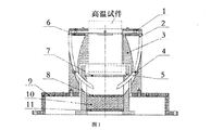
- Figure 1 is a front view of the initial state of the buffer device
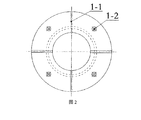
- Figure 2 is a schematic diagram of the upper cover
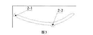
- Figure 3 is a schematic diagram of the mechanism lever
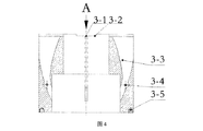
- Figure 4 is a schematic diagram of the upper support
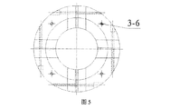
- Figure 5 is a view from the direction A of the upper support
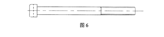
- Figure 6 is a schematic diagram of the locking shaft
- FIG. 7 is a schematic diagram of the buffer
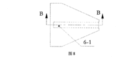
- FIG. 8 is a schematic diagram of the baffle
- Figure 9 is a sectional view of the baffle B-B
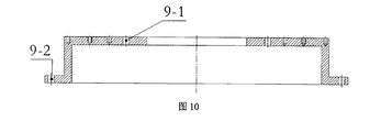
- Figure 10 is the lower support body
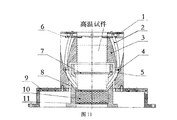
- Figure 11 is a front view of the working state of the buffer device
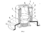
- Figure 12 is a three-dimensional schematic diagram of the buffer device
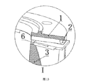
- Figure 13 is a partial enlarged view of I in Figure 12;
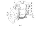
- Figure 14 is a three-dimensional schematic diagram of the buffer device with the upper cover 1 removed;
- Figure 15 is a three-dimensional cross-sectional view of the upper cover.
- the bottom of the lower support body 9 is provided with an outer flange, the outer flange of the bottom of the lower support body 9 is fixed to the inner surface of the gondola experiment cabin of the ultragravity centrifuge by bolts, and the bottom of the upper support body 3 is fixed to the top of the lower support body 9 by bolts
- There is a vertical channel in the center of the upper support body 3 a through hole slot is opened in the center of the lower support body 9, the buffer body 5 is placed in the through hole slot of the lower support body 9 and the vertical channel of the upper support body 3, and the bottom of the buffer body 5 passes
- the bolts are fixed to the hanging basket experiment cabin of the ultragravity centrifuge, and the top of the buffer body 5 is located in the bottom of the vertical channel of the upper support body 3.
- the upper support body 3 is provided with upper special-shaped grooves 3-3 with evenly spaced circumferential intervals on all four sides, and the upper end of the upper special-shaped groove 3-3 extends beyond the top surface of the upper support body 3.
- the lower end of the upper special-shaped groove 3-3 extends to the bottom edge of the inner circumferential surface.
- Each upper special-shaped groove 3-3 is equipped with a lever 2 and the upper special-shaped groove 3-3 is provided with The hinge hole 3-4, the mechanism shift lever 2 is assembled in the upper special-shaped groove 3-3 opened in the upper support body 3; the middle of the mechanism shift lever 2 is provided with a shift lever reaming hole 2-2, a shift lever reaming hole 2-2
- the middle set has a locking shaft 4, as shown in Figure 6, the two ends of the locking shaft 4 are hinged in the hinge holes 3-4 of the upper special-shaped groove 3-3, and the locking shaft 4 passes through the lever reaming hole 2-2
- the mechanism shift lever 2 is hinged to the hinge holes 3-4 in the upper support 3, so that the mechanism shift lever 2 can swing around the locking shaft 4 in a small range.
- the buffer body 5 has a vertical through hole in the middle, and the vertical through hole of the buffer body 5 is provided with a lower shaped groove 5-2 around the middle of the vertical through hole.
- the corresponding upper special-shaped groove 3-3 of the upper support body 3 and the lower special-shaped groove 5-2 of the buffer body 5 extend into the vertical through hole space of the buffer body 5, and are located close to the vertical hole of the buffer body 5 before buffering.
- the bottom of the vertical through hole is provided with a lower step 5-3, and the top of the vertical through hole is provided with an upper step 5-1.
- Both the lower step 5-3 and the upper step 5-1 are facing step surfaces, and the lower partition 11 is mounted on the lower step 5-3 of the buffer body 5, the buffer structure 10 is mounted on the lower partition 11, the lower buffer layer 8 is placed on the buffer structure 10, and the upper buffer layer 7 is mounted on the upper step 5 of the buffer body 5.
- the buffer body 5 is processed with two steps, the upper buffer layer 7 is assembled on the step above the buffer body, and the lower buffer layer 8 is assembled on the step on the bottom surface of the buffer body.
- the upper buffer layer 7 is a consumable product. When the broken sample falls, it firstly acts as a buffer and is pierced by the falling sample; the lower buffer layer 8 is made of elastic material with buffer function, which mainly plays a role of secondary buffering and heat insulation.
- each groove 3-2 is equipped with a baffle 6; the bottom of the end of the baffle 6 facing the center is provided with a baffle guide strip 6-2, a baffle guide strip 6-2 It is embedded in the guide groove 3-1 opened on the baffle 3 and moves along the guide groove 3-1 to control the movement trajectory of the baffle 3; the top of the switch lever 2 near the top is provided with a switch lever journal 2 -1, the mechanism shift lever journal 2-1 is a section with a smaller diameter and smaller than the diameter of the main body.
- a limit slot 6-1 is provided on the outer side of the stop piece 3, and the top end of the mechanism shift lever 2 passes upward through the limit set on the stop piece 3. After the slot 6-1, make the mechanism shift lever journal 2-1 and the outer surface of the stopper 6 contact and connect, the mechanism shift lever 2 swings around the locking shaft 4 and then push the stopper 6 under the action of the stopper 2 The groove 3-2 moves along the guide groove 3-1.
- the baffle plate makes the buffer device in an open state under the action of the mechanism shift lever.
- the buffer device is in a closed state, which plays a role of isolating the sample.
- the material of the upper buffer layer 7 is a consumable, and the material selection and size design should ensure that the high temperature test piece can penetrate when it falls. Provide multiple buffers. The buffering effect of the upper buffer layer reduces the impact force on the buffer body. Eventually, the flying broken sample breaks through the upper buffer layer and falls on the lower buffer layer.
- the lower buffer layer 8 is made of ceramic fiber board, which can not only play a buffer function but also insulate heat.
- the buffer structure adopts a sponge-like buffer body to completely ensure that the high-temperature fracture specimen will not cause damage to the gondola experiment chamber of the ultragravity centrifuge.
- the top of the lower support 9 is provided with a first mounting hole 9-1
- the bottom of the upper support 3 is provided with a threaded hole 3-5
- the bolt passes through the threaded hole 3 at the bottom of the upper support 3 5 is screwed to the first mounting hole 9-1 of the lower support body 9, so that the upper support body 3 is fixedly mounted on the lower support body 9.
- the second mounting hole 9- on the bottom outer flange of the lower support body 9 2 Installed in the basket experiment cabin of the ultra-gravity centrifuge by bolts.
- FIG. 1 Figure 2, Figure 5 and Figure 15, it also includes an upper cover 1.
- the bottom surface of the upper cover 1 is provided with a plurality of upper cover fixing holes 1-2, and the plurality of upper cover fixing holes 1-2 are evenly spaced along the circumference.
- the top surface of the upper support 3 is provided with a plurality of fixed threaded holes 3-6, and the plurality of fixed threaded holes 3-6 are evenly distributed along the circumference.
- the upper cover fixing holes 1-2 of the upper cover 1 and the upper support 3 The fixing threaded holes 3-6 are connected by bolts so that the upper cover 1 is fixedly installed on the upper support body 3.
- the upper cover 1 is provided with a plurality of upper cover lower grooves 1-1 for the movable guide of the top of the actuator lever 2, and the top of the actuator lever 2 is embedded in the lower groove 1-1 of the upper cover.
- test piece in the initial state, is located above the upper buffer layer 7 in the buffer device, and is not in contact with the upper buffer layer 7, and the four baffles 6 are at positions away from the central axis.
- the test piece is broken to produce a high-temperature flying-off sample.
- the high-temperature flying-off sample falls into the buffer device, it first breaks through the upper buffer layer 7 when moving to the bottom of the buffer device, and then toggles the lever 2 to wrap around the lock
- the tightening shaft 4 rotates, and the baffle 4 moves to the shaft center along the guide groove 3-1 under the action of the shift lever journal 2-1 above the mechanism shift lever 2, and the high temperature flying broken sample is enclosed in the buffer device cavity.
- the high-temperature flying-break sample finally falls on the lower buffer layer 8.
- the buffer layer 8 can isolate a certain amount of heat from the high-temperature sample.
- the buffer structure 10 serves as a buffer for the high-temperature flying-break sample to reduce impact damage to surrounding facilities.
- the inner diameters of the vertical through holes of the buffer body 5 and the vertical channels of the upper support 3 are the same, and correspond to the diameter of the test piece, that is, the diameter of the test piece is slightly smaller than the inner diameter of the vertical through hole and the vertical channel.
- the assembly and installation sequence of the components of the buffer device is: the buffer body and its internal assembly structure are installed in the gondola compartment of the ultragravity centrifuge through the bolt holes on the outer edge of the buffer body, the upper support body is assembled on the lower support body by bolts, and the lower support The body is installed concentrically with the lower buffer body in the gondola compartment of the ultra-gravity centrifuge by bolt connection, and the upper cover is installed above the upper support body.
- the buffer device can be used repeatedly, and only needs to replace the appropriate upper buffer layer 7 to meet different experimental requirements, and has the advantages of simple structure and high safety factor.
Landscapes
- General Health & Medical Sciences (AREA)
- Health & Medical Sciences (AREA)
- Life Sciences & Earth Sciences (AREA)
- Chemical & Material Sciences (AREA)
- Analytical Chemistry (AREA)
- Biochemistry (AREA)
- Physics & Mathematics (AREA)
- General Physics & Mathematics (AREA)
- Immunology (AREA)
- Pathology (AREA)
- Centrifugal Separators (AREA)
- Sampling And Sample Adjustment (AREA)
- Investigating Strength Of Materials By Application Of Mechanical Stress (AREA)
Abstract
一种超重力环境下捕获高温飞断样品的缓冲装置。下支撑体(9)底部的外凸缘固定于试验装置底座,上支撑体(3)固定于下支撑体顶部;缓冲体(5)置于下支撑体的通孔槽和上支撑体的垂直通道中;机关拨杆(2)装配于上支撑体内开设的上异形槽(3-3)内;锁紧轴(4)铰接在上异形槽的铰接孔(3-4)中;机关拨杆底部穿过上支撑体的上异形槽和缓冲体的下异形槽(5-2)后伸入到缓冲体的垂直通孔中;缓冲结构(10)装配于下层隔板(11)上;上支撑体(3)设有四个凹槽(3-2),凹槽开设导向槽(3-1)并装有挡片(6),挡片导向条(6-2)嵌装于导向槽内并沿导向槽运动;机关拨杆向上穿过挡片的限位槽(6-1)后,使得机关拨杆轴颈和挡片的外侧面接触连接。该缓冲装置装配简单、使用方便,能迅速捕获和隔离高温飞断样品,可有效解决超重力下高温飞断样品对试验舱体的破坏问题。
Description
本发明涉及缓冲装置技术领域,尤其涉及一种适用于超重力环境下捕获高温飞断样品的缓冲装置。
航天发动机涡轮叶片在服役期间长期经历高温、高压、高转速等恶劣载荷条件,叶片材料的工作性能往往是限制整机性能提升的关键因素。在服役过程中的叶片的真实受力状态为叶片自重产生的离心应力、喷气作用在叶片上的弯曲应力、热应力、振动应力、扭矩产生的剪切应力等多种应力动态耦合的体积力。而目前我国叶片设计仍主要基于常重力面力架在下材料的力学性能数据,严重偏离叶片在三维体积力-温度动态耦合状态下真实的服役环境,因此有必要借助于超重力离心机提供的超重力环境实现外加载荷在微观缺陷处的加载试验,并通过高温装置模拟材料工作时的温度场,以发展超重力场下材料的动态失效机理。
在进行试件断裂试验时,超重力下断裂的高温试件若不进行封闭处理,有可能会对离心机上的试验装置造成不可预料的结果,因此有必要设计一种缓冲装置用于封闭处理飞断样品,且应用于超重力试验装置内的缓冲装置必须具有结构简单、安全可靠的特点,设计要符合高强度轻质量的理念。
发明内容
本发明需要解决的是针对上述超重力、高温试验条件下高温飞断样品对试验装置造成破坏的问题,提供一种装配简单、使用方便、安全系数高,且可用于超重力工况的缓冲装置。
本发明采用的技术方案是:
本发明包括上盖、机关拨杆、上支撑体、锁紧轴、缓冲体、下缓冲层、缓冲结构、下层隔板、下支撑体、上缓冲层和挡片;下支撑体底部设有外凸缘,下支撑体底部的外凸缘通过螺栓固定于试验装置底座,上支撑体底部通过螺栓固定于下支撑体顶部;上支撑体中心开有垂直通道,下支撑体中央开有通孔槽,缓冲体置于下支撑体的通孔槽和上支撑体的垂直通道中,缓冲体底部通过螺栓 固定于试验装置底座;上支撑体内部的四周均开设有上异形槽,每个上异形槽内装有机关拨杆,上异形槽外圈侧壁设置有铰接孔,机关拨杆装配于上支撑体内开设的上异形槽内;机关拨杆的中部设有拨杆铰孔,拨杆铰孔中套装有锁紧轴,锁紧轴的两端铰接在上异形槽的铰接孔中,使得机关拨杆可绕锁紧轴摆动;缓冲体中间开设垂直通孔,缓冲体的垂直通孔中部四周均开设下异形槽,每个机关拨杆底部各自对应的上支撑体的上异形槽和缓冲体的下异形槽后伸入到缓冲体的垂直通孔空间中;垂直通孔底部设置有下台阶,垂直通孔顶部设置有上台阶,下层隔板装于缓冲体的下台阶上,缓冲结构装配于下层隔板上,下缓冲层置于缓冲结构上,上缓冲层装于缓冲体的上台阶上。
所述的上支撑体顶面开设有沿周向间隔均布的四个凹槽,每个凹槽中间开设沿径向的导向槽,每个凹槽内均装有挡片,挡片朝向中央的一端底面设置有挡片导向条,挡片导向条嵌装于挡片上开设的导向槽内并沿导向槽运动;机关拨杆靠近顶端的顶部设置有机关拨杆轴颈,挡片的外侧开设限位槽,机关拨杆顶端向上穿过挡片上开设的限位槽后,使得机关拨杆轴颈和挡片的外侧面接触连接,机关拨杆绕锁紧轴摆动后推动挡片在机关拨杆的作用下在凹槽内沿导向槽运动。
所述的上缓冲层材料为消耗品,在选材及尺寸设计时应保证高温试件下落时可穿透。
所述的下缓冲层采用陶瓷纤维板,既可以起到缓冲作用又可以隔绝热量,缓冲结构采用海绵状的缓冲体以彻底保证高温断裂试件不会对试验装置底座的实验舱造成损伤。
所述的下支撑体顶部开设有第一安装孔,上支撑体底部开设有螺纹孔,螺栓穿过上支撑体底部的螺纹孔和下支撑体的第一安装孔螺纹连接,从而将上支撑体固定安装于下支撑体上,装配后下支撑体底部外凸缘上的第二安装孔通过螺栓安装于试验装置底座。
还包括上盖,上盖底面开设有多个上盖固定孔,上支撑体顶面上开设有多个固定螺纹孔,上盖的上盖固定孔与上支撑体的固定螺纹孔通过螺栓连接使得,上盖固定安装于上支撑体上。
所述的上盖开设有多个用于机关拨杆顶部活动导向的上盖下凹槽,机关拨杆的顶部嵌装于上盖下凹槽内。
所述的缓冲体的垂直通孔和上支撑体的垂直通道的内径尺寸相同,且和试件的直径对应吻合。
所述装置置于超重力离心机的吊篮上,在超重力离心机运行带动下高速离 心旋转,用于超重力工况且不限于超重力工况。
本发明在上支撑体内开设四个异形槽,并在支撑体上加工四个螺纹孔,螺纹孔穿过异形槽,且与异形槽所在平面垂直;机关拨杆通过锁紧轴安装于上支撑体内部异形槽内。此外,上支撑体上部对称开设四个导向槽,四个挡片分别装配于四个导向槽内,挡片上开设有限位槽,机关拨杆上端装配于限位槽内用以控制挡片的运动,四个挡片可在机关拨杆的作用下沿导向槽向中心聚拢或呈现开启的状态。
缓冲体具有双层缓冲结构,可起到减小高温飞断样品的冲击作用,且上支撑体内配置的机关拨杆及挡片可及时的对高温飞断样品进行隔离,以防对试验舱体造成破坏。
本发明的有益效果是:
本发明缓冲装置可达到迅速将飞断样品进行隔离处理的目的,装配简单、使用方便,能迅速捕获和隔离高温飞断样品,可有效解决超重力、高温试验条件下飞断样品对周围部件的破坏问题,具有结构简单且安全系数较高的优点。
图1是缓冲装置初始状态的主视图;
图2是上盖的示意图
图3是机关拨杆的示意图
图4是上支撑体的示意图;
图5是上支撑体的A向视图;
图6是锁紧轴的示意图;
图7是缓冲体的示意图
图8是挡片的示意图;
图9是挡片B-B剖视图;
图10是下支撑体;
图11是缓冲装置工作状态的主视图;
图12是缓冲装置三维示意图;
图13是图12中I处的局部放大图;
图14是去除上盖1后的缓冲装置三维示意图;
图15是上盖的立体剖视三维示意图。
图中:1.上盖;1-1.上盖下凹槽;1-2上盖固定孔;2.机关拨杆;2-1.拨杆轴颈;2-2.拨杆铰孔;3.上支撑体;3-1.导向槽;3-2.凹槽;3-3.上异形槽;3-4.铰接 孔;3-5.螺纹孔;3-6.固定螺纹孔;4.锁紧轴;5.缓冲体;5-1.上台阶;5-2.下异形槽;5-3.下台阶;6.挡片;6-1.限位槽;6-2.导向;7.上缓冲层;8.下缓冲层;9.下支撑体;9-1.第一安装孔;9-2.第二安装孔;10.缓冲结构;11.下层隔板。
现结合附图对本发明作进一步详细的说明。这些附图均为简化的示意图,仅以示意方式说明本发明的基本结构,因此仅显示与本发明有关的构成。
如图1和图12和图14所示,包括上盖1、机关拨杆2、上支撑体3、锁紧轴4、缓冲体5、下缓冲层8、缓冲结构10、下层隔板11、下支撑体9、上缓冲层7和挡片6;下支撑体和缓冲体固定在力学性能测样品的底端;上缓冲层、上缓冲层、下缓冲体及下缓冲层装配于缓冲体内;上盖、机关拨杆、挡片、锁紧轴装配于上支撑体内;上支撑体安装于下支撑体上。下支撑体9底部设有外凸缘,下支撑体9底部的外凸缘通过螺栓固定于超重力离心机的吊篮实验舱内表面,上支撑体3底部通过螺栓固定于下支撑体9顶部;上支撑体3中心开有垂直通道,下支撑体9中央开有通孔槽,缓冲体5置于下支撑体9的通孔槽和上支撑体3的垂直通道中,缓冲体5底部通过螺栓固定于超重力离心机的吊篮实验舱,,缓冲体5顶部位于上支撑体3的垂直通道底部中。
如图4、图12和图14所示,上支撑体3内部的四周均开设有圆周间隔均布的上异形槽3-3,上异形槽3-3上端延伸到上支撑体3顶面外边缘和外侧壁上边缘,上异形槽3-3下端延伸到内周面的底部边缘,每个上异形槽3-3内装有机关拨杆2,上异形槽3-3外圈侧壁设置有铰接孔3-4,机关拨杆2装配于上支撑体3内开设的上异形槽3-3内;机关拨杆2的中部设有拨杆铰孔2-2,拨杆铰孔2-2中套装有锁紧轴4,如图6所示,锁紧轴4的两端铰接在上异形槽3-3的铰接孔3-4中,锁紧轴4穿过拨杆铰孔2-2将机关拨杆2铰接于上支撑体3内的铰接孔3-4处,使得机关拨杆2可绕锁紧轴4在小范围内摆动。
如图1、图7、图12和图14所示,缓冲体5中间开设垂直通孔,缓冲体5的垂直通孔中部四周均开设下异形槽5-2,每个机关拨杆2底部各自对应的上支撑体3的上异形槽3-3和缓冲体5的下异形槽5-2后伸入到缓冲体5的垂直通孔空间中,并且在缓冲前位于靠近到缓冲体5的垂直通孔中央处;垂直通孔底部设置有下台阶5-3,垂直通孔顶部设置有上台阶5-1,下台阶5-3和上台阶5-1均为朝向的台阶面,下层隔板11装于缓冲体5的下台阶5-3上,缓冲结构10装配于下层隔板11上,下缓冲层8置于缓冲结构10上,上缓冲层7装于缓冲体5的上台阶5-1上;缓冲体5内加工有两个台阶,上缓冲层7装配于缓冲体上 方的台阶上,下缓冲层8装配于缓冲体底面的台阶上。上缓冲层7为易耗品,断裂样品坠落时首先起到缓冲作用,并被坠样品穿破;下缓冲层8采用弹性具有缓冲功能的材料,主要起到二次缓冲及隔热的作用。
如图1、图3、图8、图9和图13所示,上支撑体3顶面开设有沿周向间隔均布的四个凹槽3-2,每个凹槽3-2中间开设沿径向的导向槽3-1,每个凹槽3-2内均装有挡片6,挡片6朝向中央的一端底面设置有挡片导向条6-2,挡片导向条6-2嵌装于挡片3上开设的导向槽3-1内并沿导向槽3-1运动,用以控制挡片3的运动轨迹;机关拨杆2靠近顶端的顶部设置有机关拨杆轴颈2-1,机关拨杆轴颈2-1为直径较小、小于主体直径的一段,挡片3的外侧开设限位槽6-1,机关拨杆2顶端向上穿过挡片3上开设的限位槽6-1后,使得机关拨杆轴颈2-1和挡片6的外侧面接触连接,机关拨杆2绕锁紧轴4摆动后推动挡片6在机关拨杆2的作用下在凹槽3-2内沿导向槽3-1运动。
初始状态下,挡片在机关拨杆作用下使缓冲装置处于开启状态,挡片6在机关拨杆作用下向上支撑体轴心处聚拢时使缓冲装置处于关闭状态,起到隔离样品的作用。
具体实施中,上缓冲层7材料为消耗品,在选材及尺寸设计时应保证高温试件下落时可穿透。提供多次缓冲,试件经过上缓冲层的缓冲作用降低了对缓冲体的冲击力,最终飞断样品穿破上缓冲层掉落在下缓冲层上。
下缓冲层8采用陶瓷纤维板,既可以起到缓冲作用又可以隔绝热量,缓冲结构采用海绵状的缓冲体以彻底保证高温断裂试件不会对超重力离心机的吊篮实验舱造成损伤。
如图1和图10所示,下支撑体9顶部开设有第一安装孔9-1,上支撑体3底部开设有螺纹孔3-5,螺栓穿过上支撑体3底部的螺纹孔3-5和下支撑体9的第一安装孔9-1螺纹连接,从而将上支撑体3固定安装于下支撑体9上,装配后下支撑体9底部外凸缘上的第二安装孔9-2通过螺栓安装于超重力离心机的吊篮实验舱。
如图1、图2、图5和图15所示,还包括上盖1,上盖1底面开设有多个上盖固定孔1-2,多个上盖固定孔1-2沿圆周间隔均布,上支撑体3顶面上开设有多个固定螺纹孔3-6,多个固定螺纹孔3-6沿圆周间隔均布,上盖1的上盖固定孔1-2与上支撑体3的固定螺纹孔3-6通过螺栓连接使得,上盖1固定安装于上支撑体3上。上盖1开设有多个用于机关拨杆2顶部活动导向的上盖下凹槽1-1,机关拨杆2的顶部嵌装于上盖下凹槽1-1内。
如图1所示,在初始状态时,试件位于缓冲装置中上缓冲层7的上方,且 不与上缓冲层7接触,四个挡片6在远离中心轴线的位置。
如图11所示,试件发生断裂产生高温飞断样品,在高温飞断样品坠入缓冲装置内部时,向缓冲装置底部运动时首先冲破上缓冲层7,继而拨动机关拨杆2绕锁紧轴4转动,挡片4在机关拨杆2上方拨杆轴颈2-1作用下沿导向槽3-1向轴心处运动,将高温飞断样品封闭于缓冲装置腔内。高温飞断样品最终落在下缓冲层8上,缓冲层8对高温样品起到隔绝一定热量的作用,同时缓冲结构10在高温飞断样品起到缓冲作用,减小对周围设施造成的冲击损伤。
缓冲体5的垂直通孔和上支撑体3的垂直通道的内径尺寸相同,且和试件的直径对应吻合,即试件的直径略小于垂直通孔和垂直通道的内径。
缓冲装置零部件的装配安装顺序为:缓冲体及其内部装配结构通过缓冲体外缘的螺栓孔安装于超重力离心机的吊篮舱体内,上支撑体通过螺栓装配于下支撑体上,下支撑体通过螺栓连接的方式与下缓冲体同心安装于超重力离心机的吊篮舱体内,上盖安装于上支撑体上方。
缓冲装置可重复使用,仅需要通过更换合适的上缓冲层7以满足不同的实验要求,具有结构简单且安全系数较高的优点。
Claims (8)
- 一种超重力环境下捕获高温飞断样品的缓冲装置,其特征在于:包括上盖1、机关拨杆2、上支撑体3、锁紧轴4、缓冲体5、下缓冲层8、缓冲结构10、下层隔板11、下支撑体9、上缓冲层7和挡片6;下支撑体9底部设有外凸缘,下支撑体9底部的外凸缘通过螺栓固定于试验装置底座,上支撑体3底部通过螺栓固定于下支撑体9顶部;上支撑体3中心开有垂直通道,下支撑体9中央开有通孔槽,缓冲体5置于下支撑体9的通孔槽和上支撑体3的垂直通道中,缓冲体5底部通过螺栓固定于试验装置底座;上支撑体3内部的四周均开设有上异形槽3-3,每个上异形槽3-3内装有机关拨杆2,上异形槽3-3外圈侧壁设置有铰接孔3-4,机关拨杆2装配于上支撑体3内开设的上异形槽3-3内;机关拨杆2的中部设有拨杆铰孔2-2,拨杆铰孔2-2中套装有锁紧轴4,锁紧轴4的两端铰接在上异形槽3-3的铰接孔3-4中,使得机关拨杆2可绕锁紧轴4摆动;缓冲体5中间开设垂直通孔,缓冲体5的垂直通孔中部四周均开设下异形槽5-2,每个机关拨杆2底部各自对应的上支撑体3的上异形槽3-3和缓冲体5的下异形槽5-2后伸入到缓冲体5的垂直通孔空间中;垂直通孔底部设置有下台阶5-3,垂直通孔顶部设置有上台阶5-1,下层隔板11装于缓冲体5的下台阶5-3上,缓冲结构10装配于下层隔板11上,下缓冲层8置于缓冲结构10上,上缓冲层7装于缓冲体5的上台阶5-1上;所述的上支撑体3顶面开设有沿周向间隔均布的四个凹槽3-2,每个凹槽3-2中间开设沿径向的导向槽3-1,每个凹槽3-2内均装有挡片6,挡片6朝向中央的一端底面设置有挡片导向条6-2,挡片导向条6-2嵌装于挡片3上开设的导向槽3-1内并沿导向槽3-1运动;机关拨杆2靠近顶端的顶部设置有机关拨杆轴颈2-1,挡片3的外侧开设限位槽6-1,机关拨杆2顶端向上穿过挡片3上开设的限位槽6-1后,使得机关拨杆轴颈2-1和挡片6的外侧面接触连接,机关拨杆2绕锁紧轴4摆动后推动挡片6在机关拨杆2的作用下在凹槽3-2内沿导向槽3-1运动。
- 根据权利要求1所述的一种超重力环境下捕获高温飞断样品的缓冲装置,其特征在于:所述的上缓冲层7材料为消耗品,在选材及尺寸设计时应保证高温试件下落时可穿透。
- 根据权利要求1所述的一种超重力环境下捕获高温飞断样品的缓冲装置,其特征在于:所述的下缓冲层8采用陶瓷纤维板,既可以起到缓冲作用又 可以隔绝热量,缓冲结构采用海绵状的缓冲体以彻底保证高温断裂试件不会对试验装置底座的实验舱造成损伤。
- 根据权利要求1所述的一种超重力环境下捕获高温飞断样品的缓冲装置,其特征在于:所述的下支撑体9顶部开设有第一安装孔9-1,上支撑体3底部开设有螺纹孔3-5,螺栓穿过上支撑体3底部的螺纹孔3-5和下支撑体9的第一安装孔9-1螺纹连接,从而将上支撑体3固定安装于下支撑体9上,装配后下支撑体9底部外凸缘上的第二安装孔9-2通过螺栓安装于试验装置底座。
- 根据权利要求1所述的一种超重力环境下捕获高温飞断样品的缓冲装置,其特征在于:还包括上盖1,上盖1底面开设有多个上盖固定孔1-2,上支撑体3顶面上开设有多个固定螺纹孔3-6,上盖1的上盖固定孔1-2与上支撑体3的固定螺纹孔3-6通过螺栓连接使得,上盖1固定安装于上支撑体3上。
- 根据权利要求5所述的一种超重力环境下捕获高温飞断样品的缓冲装置,其特征在于:所述的上盖1开设有多个用于机关拨杆2顶部活动导向的上盖下凹槽1-1,机关拨杆2的顶部嵌装于上盖下凹槽1-1内。
- 根据权利要求1所述的一种超重力环境下捕获高温飞断样品的缓冲装置,其特征在于:所述的缓冲体5的垂直通孔和上支撑体3的垂直通道的内径尺寸相同,且和试件的直径对应吻合。
- 根据权利要求1所述的一种超重力环境下捕获高温飞断样品的缓冲装置,其特征在于:所述装置置于超重力离心机的吊篮上,用于超重力工况且不限于超重力工况。
Applications Claiming Priority (2)
| Application Number | Priority Date | Filing Date | Title |
|---|---|---|---|
| CN201910285339.3 | 2019-04-10 | ||
| CN201910285339.3A CN110006741B (zh) | 2019-04-10 | 2019-04-10 | 一种超重力环境下捕获高温飞断样品的缓冲装置 |
Publications (2)
| Publication Number | Publication Date |
|---|---|
| WO2020206715A1 true WO2020206715A1 (zh) | 2020-10-15 |
| WO2020206715A8 WO2020206715A8 (zh) | 2021-09-16 |
Family
ID=67170856
Family Applications (1)
| Application Number | Title | Priority Date | Filing Date |
|---|---|---|---|
| PCT/CN2019/083492 Ceased WO2020206715A1 (zh) | 2019-04-10 | 2019-04-19 | 一种超重力环境下捕获高温飞断样品的缓冲装置 |
Country Status (2)
| Country | Link |
|---|---|
| CN (1) | CN110006741B (zh) |
| WO (1) | WO2020206715A1 (zh) |
Families Citing this family (4)
| Publication number | Priority date | Publication date | Assignee | Title |
|---|---|---|---|---|
| CN110261238B (zh) | 2019-06-20 | 2024-04-05 | 浙江大学 | 超重力环境固定式多场耦合作用下材料性能测试系统 |
| CN110426281B (zh) * | 2019-07-29 | 2021-12-24 | 泸州临港工业化建筑科技有限公司 | 一种建筑钢结构强度检测装置 |
| CN110605146B (zh) * | 2019-09-10 | 2023-07-25 | 浙江大学 | 机载超重离心模拟装置的多功能实验舱 |
| CN112326894A (zh) * | 2020-11-26 | 2021-02-05 | 贵州航天精工制造有限公司 | 一种用于相配异形件贴合度检测的快速紧固工装 |
Citations (6)
| Publication number | Priority date | Publication date | Assignee | Title |
|---|---|---|---|---|
| SU1610374A2 (ru) * | 1988-11-04 | 1990-11-30 | Тольяттинский политехнический институт | Устройство дл испытани на разрыв деталей типа тел вращени |
| DE202006014772U1 (de) * | 2006-04-21 | 2006-12-28 | Schröder-Rentrop, Karl-Dietrich | Spreizvorrichtung für Wellensicherungsringe zur Prüfung von Inhibitorenwirksamkeit |
| CN205981871U (zh) * | 2016-08-24 | 2017-02-22 | 浙江昂星链条有限公司 | 一种用于轴类工件的脆性测试机 |
| CN206496964U (zh) * | 2017-02-24 | 2017-09-15 | 安徽理工大学 | 一种劈裂试验压力机的试样收集及防护装置 |
| CN108132199A (zh) * | 2018-01-30 | 2018-06-08 | 重庆大学 | 一种超高温材料批量热冲击测试装置 |
| CN207516144U (zh) * | 2017-11-16 | 2018-06-19 | 中国人民解放军陆军工程大学 | 一种基于万能试验机的实时保护观测记录和隔音装置 |
Family Cites Families (8)
| Publication number | Priority date | Publication date | Assignee | Title |
|---|---|---|---|---|
| JP3871817B2 (ja) * | 1998-09-09 | 2007-01-24 | 株式会社ウイ・プラン | 各種断面材の引張試験装置 |
| DE202006003197U1 (de) * | 2006-03-01 | 2007-07-12 | Hettich-Oni Gmbh & Co. Kg | Dämpfer für Möbel |
| CN104335698B8 (en) * | 2007-11-15 | 2015-04-29 | Shanghai Aerospace System Engineering Inst | Variable stiffness bi-directional buffer device of docking mechanism of aircraft |
| US20140369826A1 (en) * | 2012-10-05 | 2014-12-18 | Steven Rohring | Tornado wind energy conversion system wind turbine |
| CN103381985B (zh) * | 2013-06-26 | 2015-10-28 | 杨伦 | 一种电梯坠落的缓冲装置 |
| CN205220964U (zh) * | 2015-12-09 | 2016-05-11 | 重庆业达机械制造有限公司 | 一种缓冲盘组件 |
| CN106516389B (zh) * | 2016-11-09 | 2018-09-07 | 成都世唯科技有限公司 | 一种用于成品酒包装的一体化防断式阮塞 |
| CN206740507U (zh) * | 2017-04-24 | 2017-12-12 | 广州市广材试验仪器有限公司 | 一种卧式拉力试验机缓冲装置 |
-
2019
- 2019-04-10 CN CN201910285339.3A patent/CN110006741B/zh active Active
- 2019-04-19 WO PCT/CN2019/083492 patent/WO2020206715A1/zh not_active Ceased
Patent Citations (6)
| Publication number | Priority date | Publication date | Assignee | Title |
|---|---|---|---|---|
| SU1610374A2 (ru) * | 1988-11-04 | 1990-11-30 | Тольяттинский политехнический институт | Устройство дл испытани на разрыв деталей типа тел вращени |
| DE202006014772U1 (de) * | 2006-04-21 | 2006-12-28 | Schröder-Rentrop, Karl-Dietrich | Spreizvorrichtung für Wellensicherungsringe zur Prüfung von Inhibitorenwirksamkeit |
| CN205981871U (zh) * | 2016-08-24 | 2017-02-22 | 浙江昂星链条有限公司 | 一种用于轴类工件的脆性测试机 |
| CN206496964U (zh) * | 2017-02-24 | 2017-09-15 | 安徽理工大学 | 一种劈裂试验压力机的试样收集及防护装置 |
| CN207516144U (zh) * | 2017-11-16 | 2018-06-19 | 中国人民解放军陆军工程大学 | 一种基于万能试验机的实时保护观测记录和隔音装置 |
| CN108132199A (zh) * | 2018-01-30 | 2018-06-08 | 重庆大学 | 一种超高温材料批量热冲击测试装置 |
Also Published As
| Publication number | Publication date |
|---|---|
| WO2020206715A8 (zh) | 2021-09-16 |
| CN110006741A (zh) | 2019-07-12 |
| CN110006741B (zh) | 2020-07-03 |
Similar Documents
| Publication | Publication Date | Title |
|---|---|---|
| CN110006741B (zh) | 一种超重力环境下捕获高温飞断样品的缓冲装置 | |
| WO2023240722A1 (zh) | 一种基于霍普金森杆系统的动载剪切试验装置及方法 | |
| CN110261238A (zh) | 超重力环境固定式多场耦合作用下材料性能测试系统 | |
| US20120006965A1 (en) | Damping device of stay cable | |
| CN103162953B (zh) | 一种自润滑衬垫性能试验机 | |
| CN106871748A (zh) | 用于弹体多角度高速旋转条件下测试弹翼展开的旋转台 | |
| CN209247560U (zh) | 一种刹车片摩擦试验装置 | |
| US2809802A (en) | Damping turbine blades | |
| RU2653980C2 (ru) | Вспомогательное устройство для выполнения манипуляций с капотом и гондола турбореактивного двигателя, оснащенная таким устройством | |
| CN114132488B (zh) | 一种基于互联网大数据的输电巡检装置 | |
| CN103527259B (zh) | 涡轮转子的减压平衡 | |
| CN210636619U (zh) | 一种摩擦型消能减震阻尼器 | |
| CN104214272A (zh) | 一种平衡重随行制动装置 | |
| CN108801621A (zh) | 模拟机动飞行条件下航空发动机转子盘腔积液的装置 | |
| US3142172A (en) | Vibration testing apparatus | |
| WO2025118824A1 (zh) | 管道隔振装置 | |
| CN105865264A (zh) | 一种火箭发射架减震机构及其工作方法 | |
| CN113670603B (zh) | 电力机车用超低温齿轮箱测试装置 | |
| CN210923332U (zh) | 一种超重力环境固定式多场耦合作用下材料性能测试系统 | |
| CN205374159U (zh) | 一种简易高温拉伸蠕变试验用装置箱式炉的保温结构 | |
| CN110792794B (zh) | 大口径高温管道专用的陶瓷闸板阀 | |
| CN103760012A (zh) | 霍普金森试验试件保温装置 | |
| CN211099596U (zh) | 一种多工作空间的台式高速冷冻离心机 | |
| CN104314399A (zh) | 门板支撑及动力缓冲装置 | |
| CN214334994U (zh) | 一种用于微流控芯片进样的离心进样仪 |
Legal Events
| Date | Code | Title | Description |
|---|---|---|---|
| 121 | Ep: the epo has been informed by wipo that ep was designated in this application |
Ref document number: 19924056 Country of ref document: EP Kind code of ref document: A1 |
|
| NENP | Non-entry into the national phase |
Ref country code: DE |
|
| 122 | Ep: pct application non-entry in european phase |
Ref document number: 19924056 Country of ref document: EP Kind code of ref document: A1 |