WO2020204147A1 - 作業現場の管理システム及び作業現場の管理方法 - Google Patents
作業現場の管理システム及び作業現場の管理方法 Download PDFInfo
- Publication number
- WO2020204147A1 WO2020204147A1 PCT/JP2020/015247 JP2020015247W WO2020204147A1 WO 2020204147 A1 WO2020204147 A1 WO 2020204147A1 JP 2020015247 W JP2020015247 W JP 2020015247W WO 2020204147 A1 WO2020204147 A1 WO 2020204147A1
- Authority
- WO
- WIPO (PCT)
- Prior art keywords
- vehicle
- loading
- work
- manned vehicle
- command
- Prior art date
- Legal status (The legal status is an assumption and is not a legal conclusion. Google has not performed a legal analysis and makes no representation as to the accuracy of the status listed.)
- Ceased
Links
Images








Classifications
-
- G—PHYSICS
- G08—SIGNALLING
- G08G—TRAFFIC CONTROL SYSTEMS
- G08G1/00—Traffic control systems for road vehicles
- G08G1/09—Arrangements for giving variable traffic instructions
- G08G1/0962—Arrangements for giving variable traffic instructions having an indicator mounted inside the vehicle, e.g. giving voice messages
- G08G1/0967—Systems involving transmission of highway information, e.g. weather, speed limits
- G08G1/096766—Systems involving transmission of highway information, e.g. weather, speed limits where the system is characterised by the origin of the information transmission
- G08G1/096775—Systems involving transmission of highway information, e.g. weather, speed limits where the system is characterised by the origin of the information transmission where the origin of the information is a central station
-
- E—FIXED CONSTRUCTIONS
- E02—HYDRAULIC ENGINEERING; FOUNDATIONS; SOIL SHIFTING
- E02F—DREDGING; SOIL-SHIFTING
- E02F9/00—Component parts of dredgers or soil-shifting machines, not restricted to one of the kinds covered by groups E02F3/00 - E02F7/00
- E02F9/20—Drives; Control devices
- E02F9/2025—Particular purposes of control systems not otherwise provided for
- E02F9/205—Remotely operated machines, e.g. unmanned vehicles
-
- E—FIXED CONSTRUCTIONS
- E02—HYDRAULIC ENGINEERING; FOUNDATIONS; SOIL SHIFTING
- E02F—DREDGING; SOIL-SHIFTING
- E02F9/00—Component parts of dredgers or soil-shifting machines, not restricted to one of the kinds covered by groups E02F3/00 - E02F7/00
- E02F9/20—Drives; Control devices
-
- E—FIXED CONSTRUCTIONS
- E02—HYDRAULIC ENGINEERING; FOUNDATIONS; SOIL SHIFTING
- E02F—DREDGING; SOIL-SHIFTING
- E02F9/00—Component parts of dredgers or soil-shifting machines, not restricted to one of the kinds covered by groups E02F3/00 - E02F7/00
- E02F9/20—Drives; Control devices
- E02F9/2025—Particular purposes of control systems not otherwise provided for
- E02F9/2054—Fleet management
-
- E—FIXED CONSTRUCTIONS
- E02—HYDRAULIC ENGINEERING; FOUNDATIONS; SOIL SHIFTING
- E02F—DREDGING; SOIL-SHIFTING
- E02F9/00—Component parts of dredgers or soil-shifting machines, not restricted to one of the kinds covered by groups E02F3/00 - E02F7/00
- E02F9/26—Indicating devices
- E02F9/261—Surveying the work-site to be treated
- E02F9/262—Surveying the work-site to be treated with follow-up actions to control the work tool, e.g. controller
-
- G—PHYSICS
- G06—COMPUTING OR CALCULATING; COUNTING
- G06Q—INFORMATION AND COMMUNICATION TECHNOLOGY [ICT] SPECIALLY ADAPTED FOR ADMINISTRATIVE, COMMERCIAL, FINANCIAL, MANAGERIAL OR SUPERVISORY PURPOSES; SYSTEMS OR METHODS SPECIALLY ADAPTED FOR ADMINISTRATIVE, COMMERCIAL, FINANCIAL, MANAGERIAL OR SUPERVISORY PURPOSES, NOT OTHERWISE PROVIDED FOR
- G06Q10/00—Administration; Management
- G06Q10/06—Resources, workflows, human or project management; Enterprise or organisation planning; Enterprise or organisation modelling
-
- G—PHYSICS
- G06—COMPUTING OR CALCULATING; COUNTING
- G06Q—INFORMATION AND COMMUNICATION TECHNOLOGY [ICT] SPECIALLY ADAPTED FOR ADMINISTRATIVE, COMMERCIAL, FINANCIAL, MANAGERIAL OR SUPERVISORY PURPOSES; SYSTEMS OR METHODS SPECIALLY ADAPTED FOR ADMINISTRATIVE, COMMERCIAL, FINANCIAL, MANAGERIAL OR SUPERVISORY PURPOSES, NOT OTHERWISE PROVIDED FOR
- G06Q50/00—Information and communication technology [ICT] specially adapted for implementation of business processes of specific business sectors, e.g. utilities or tourism
- G06Q50/02—Agriculture; Fishing; Forestry; Mining
-
- E—FIXED CONSTRUCTIONS
- E02—HYDRAULIC ENGINEERING; FOUNDATIONS; SOIL SHIFTING
- E02F—DREDGING; SOIL-SHIFTING
- E02F3/00—Dredgers; Soil-shifting machines
- E02F3/04—Dredgers; Soil-shifting machines mechanically-driven
- E02F3/28—Dredgers; Soil-shifting machines mechanically-driven with digging tools mounted on a dipper- or bucket-arm, i.e. there is either one arm or a pair of arms, e.g. dippers, buckets
- E02F3/36—Component parts
-
- G—PHYSICS
- G06—COMPUTING OR CALCULATING; COUNTING
- G06Q—INFORMATION AND COMMUNICATION TECHNOLOGY [ICT] SPECIALLY ADAPTED FOR ADMINISTRATIVE, COMMERCIAL, FINANCIAL, MANAGERIAL OR SUPERVISORY PURPOSES; SYSTEMS OR METHODS SPECIALLY ADAPTED FOR ADMINISTRATIVE, COMMERCIAL, FINANCIAL, MANAGERIAL OR SUPERVISORY PURPOSES, NOT OTHERWISE PROVIDED FOR
- G06Q50/00—Information and communication technology [ICT] specially adapted for implementation of business processes of specific business sectors, e.g. utilities or tourism
- G06Q50/08—Construction
Definitions
- This disclosure relates to a work site management system and a work site management method.
- Unmanned vehicles may operate at wide-area work sites such as mines.
- a manned vehicle may operate together with an unmanned vehicle.
- the loading machine needs to load the cargo into each of the unmanned vehicle and the manned vehicle at the loading site. If the procedure for loading work on an unmanned vehicle and the procedure for loading work on a manned vehicle are different, the burden on the operator who operates the loading machine increases, and as a result, the work efficiency decreases.
- a command unit that outputs a work command to the unmanned vehicle and the manned vehicle based on input data from a work machine operating at a work site where the unmanned vehicle and the manned vehicle coexist. To be equipped.
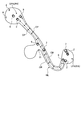
- FIG. 1 is a diagram schematically showing an example of a management system, an unmanned vehicle, and a manned vehicle according to the present embodiment.
- FIG. 2 is a diagram schematically showing an example of a work site according to the present embodiment.
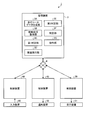
- FIG. 3 is a functional block diagram showing an example of the management system according to the present embodiment.
- FIG. 4 is a diagram schematically showing an example of a loading site according to the present embodiment.
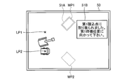
- FIG. 5 is a diagram schematically showing an example of a notification device according to the present embodiment.
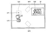
- FIG. 6 is a diagram schematically showing an example of the notification device according to the present embodiment.
- FIG. 7 is a schematic view showing an example of the management method according to the present embodiment.
- FIG. 8 is a schematic view showing an example of the management method according to the present embodiment.
- FIG. 1 is a diagram schematically showing an example of a management system, an unmanned vehicle, and a manned vehicle according to the present embodiment.
- FIG. 2 is a diagram schematically showing an
- FIG. 9 is a schematic view showing an example of the management method according to the present embodiment.
- FIG. 10 is a schematic view showing an example of the management method according to the present embodiment.
- FIG. 11 is a schematic view showing an example of the management method according to the present embodiment.
- FIG. 12 is a schematic view showing an example of the management method according to the present embodiment.
- FIG. 13 is a schematic view showing an example of the management method according to the present embodiment.
- FIG. 14 is a flowchart showing an example of the management method according to the present embodiment.
- FIG. 15 is a schematic view showing an example of the management method according to the present embodiment.
- FIG. 16 is a schematic view showing an example of the management method according to the present embodiment.
- FIG. 17 is a schematic view showing an example of the management method according to the present embodiment.
- FIG. 18 is a schematic view showing an example of the management method according to the present embodiment.
- FIG. 19 is a block diagram showing an example of a computer system.
- FIG. 1 is a diagram schematically showing an example of a management system 1, an unmanned vehicle 2, a manned vehicle 9, and a loading machine 7 according to the present embodiment.
- Each of the unmanned vehicle 2, the manned vehicle 9, and the loading machine 7 operates at the work site.
- the work site is a mine or quarry.
- a mine is a place or place of business where minerals are mined.
- the unmanned vehicle 2 refers to a vehicle that operates unmanned regardless of the driving operation by the driver.
- the manned vehicle 9 refers to a vehicle that is operated by the driving operation of the driver.
- the loading machine 7 refers to a work machine for loading a load into an unmanned vehicle 2 and a manned vehicle 9.
- the unmanned vehicle 2 and the manned vehicle 9 are dump trucks, which are a type of transport vehicle that travels on the work site and transports cargo.
- the loading machine 7 is, for example, a hydraulic excavator having a working machine including a bucket.
- Examples of the cargo carried to the unmanned vehicle 2 and the manned vehicle 9 include ore or earth and sand excavated in a mine or a quarry.
- the loading machine 7 may be, for example, a rope excavator or a wheel loader having a working machine including a bucket.
- the work site is not limited to mines or quarries.
- the work site may be any work site where the transport vehicle carries the cargo.
- the management system 1 includes a management device 3, a communication system 4, an unmanned vehicle 2, a manned vehicle 9, and a loading machine 7.
- the management device 3 includes a computer system and is installed in, for example, a control facility 5 at a work site.
- the communication system 4 carries out communication between the management device 3, the unmanned vehicle 2, the manned vehicle 9, and the loading machine 7.
- the wireless communication device 6 is connected to the management device 3.
- the communication system 4 includes a wireless communication device 6.
- the management device 3, the unmanned vehicle 2, the manned vehicle 9, and the loading machine 7 wirelessly communicate with each other via the communication system 4.
- the unmanned vehicle 2 travels on the work site based on, for example, travel course data transmitted from the management device 3.
- the unmanned vehicle 2 includes a traveling device 21, a vehicle body 22 supported by the traveling device 21, a dump body 23 supported by the vehicle body 22, and a control device 30.
- the traveling device 21 includes a driving device 24 for driving the traveling device 21, a braking device 25 for braking the traveling device 21, a steering device 26 for adjusting the traveling direction, and wheels 27.
- the unmanned vehicle 2 self-propells due to the rotation of the wheels 27.
- the wheel 27 includes a front wheel 27F and a rear wheel 27R. Tires are mounted on the wheels 27.
- the drive device 24 generates a driving force for accelerating the unmanned vehicle 2.
- the drive unit 24 includes an internal combustion engine such as a diesel engine.
- the drive device 24 may include an electric motor.
- the power generated by the drive device 24 is transmitted to the rear wheels 27R.
- the braking device 25 generates a braking force for decelerating or stopping the unmanned vehicle 2.
- the steering device 26 can adjust the traveling direction of the unmanned vehicle 2.
- the traveling direction of the unmanned vehicle 2 includes the direction of the front portion of the vehicle body 22.
- the steering device 26 adjusts the traveling direction of the unmanned vehicle 2 by steering the front wheels 27F.
- the control device 30 can communicate with the management device 3 existing outside the unmanned vehicle 2.
- the control device 30 outputs an accelerator command for operating the drive device 24, a brake command for operating the brake device 25, and a steering command for operating the steering device 26.
- the driving device 24 generates a driving force for accelerating the unmanned vehicle 2 based on the accelerator command output from the control device 30.
- the brake device 25 generates a braking force for decelerating the unmanned vehicle 2 based on the brake command output from the control device 30.
- the steering device 26 generates a force for changing the direction of the front wheels 27F in order to drive the unmanned vehicle 2 straight or turn based on the steering command output from the control device 30.
- the unmanned vehicle 2 includes a position detecting device 28 that detects the position of the unmanned vehicle 2.
- the position of the unmanned vehicle 2 is detected by using a global navigation satellite system (GNSS: Global Navigation Satellite System).
- the Global Navigation Satellite System includes the Global Positioning System (GPS).
- GPS Global Positioning System
- the global navigation satellite system detects the absolute position of the unmanned vehicle 2 defined by the coordinate data of latitude, longitude, and altitude.
- the global navigation satellite system detects the position of the unmanned vehicle 2 defined in the global coordinate system.
- the global coordinate system is a coordinate system fixed to the earth.
- the position detection device 28 includes a GNSS receiver and detects the absolute position (coordinates) of the unmanned vehicle 2.
- the unmanned vehicle 2 is equipped with a wireless communication device 29.
- Communication system 4 includes a wireless communication device 29.
- the wireless communication device 29 can wirelessly communicate with the management device 3.
- the manned vehicle 9 travels on the work site based on the driving operation of the driver who is in the driver's cab of the manned vehicle 9.
- the manned vehicle 9 includes a traveling device 21, a vehicle body 22, a dump body 23, a driving device 24, a braking device 25, a steering device 26, wheels 27 including front wheels 27F and rear wheels 27R, and a position detection device.
- a 28, a wireless communication device 29, a control device 40, and a notification device 50 are provided.
- the position detection device 28 of the manned vehicle 9 detects the position of the manned vehicle 9.
- the wireless communication device 29 of the manned vehicle 9 can wirelessly communicate with the management device 3.
- the control device 40 can communicate with the management device 3 existing outside the manned vehicle 9.
- An accelerator pedal for operating the drive device 24, a brake pedal for operating the brake device 25, and a steering wheel for operating the steering device 26 are arranged in the driver's cab.
- the accelerator pedal, brake pedal, and steering wheel are operated by the driver.
- the driving device 24 generates a driving force for accelerating the manned vehicle 9 based on the amount of operation of the accelerator pedal.
- the brake device 25 generates a braking force for decelerating the manned vehicle 9 based on the amount of operation of the brake pedal.
- the steering device 26 generates a force for changing the direction of the front wheels 27F in order to move the manned vehicle 9 straight or turn based on the amount of operation of the steering wheel.
- the notification device 50 is arranged in the driver's cab.
- the notification device 50 operates based on the notification data transmitted from the management device 3.
- the notification device 50 notifies a work command described later.
- Examples of the notification device 50 include a display device that displays display data and a voice output device that outputs voice.
- Examples of the display device include a flat panel display such as a liquid crystal display (LCD) or an organic EL display (OLELD).
- the loading machine 7 carries out the loading work based on the operation of the operator who boarded the operation room of the loading machine 7.
- the loading machine 7 includes a working machine 70, a traveling body 71, a swivel body 72, a position detecting device 28, a wireless communication device 29, a control device 60, and an input device 80.
- the working machine 70 includes a boom, an arm, and a bucket.
- the control device 60 can communicate with the management device 3 existing outside the loading machine 7.
- a work lever for operating the work machine 70, a traveling lever for operating the traveling body 71, and a swivel lever for turning the swivel body 72 are arranged in the operation room.
- the work lever, the traveling lever, and the swivel lever are operated by the operator.
- the work machine 70 performs excavation operation and dump operation based on the operation amount of the work lever.
- the traveling body 71 travels and stops based on the amount of operation of the traveling lever.
- the swivel body 72 swivels around a swivel shaft based on the amount of operation of the swivel lever.
- the input device 80 is arranged in, for example, an operation room.
- the input device 80 generates input data by being operated by an operator.
- Examples of the input device 80 include buttons, switches, and a touch panel.
- FIG. 2 is a diagram schematically showing an example of a work site according to the present embodiment.
- the unmanned vehicle 2 and the manned vehicle 9 travel on at least a part of the mine workshop PA and the runway HL leading to the workshop PA.
- the workplace PA includes at least one of a loading site LPA and a soil removal site DPA.
- the runway HL includes, for example, an intersection IS.
- Loading area LPA refers to the area where the loading work for loading the cargo on the unmanned vehicle 2 and the manned vehicle 9 is carried out.
- the loading machine 7 operates at the loading site LPA.
- the soil removal site DPA is an area where the soil removal work is carried out in which the cargo is discharged from the unmanned vehicle 2 and the manned vehicle 9.
- a crusher 8 is provided in the soil removal site DPA.
- the crusher 8 refers to a work machine that crushes the cargo discharged from the unmanned vehicle 2 and the manned vehicle 9.
- the unmanned vehicle 2 travels on the work site based on the traveling course data indicating the traveling conditions of the unmanned vehicle 2.
- the running course data includes a plurality of course point CPs set at intervals.
- the course point CP defines the target position of the unmanned vehicle 2.
- the target traveling speed and the target traveling direction of the unmanned vehicle 2 are set for each of the plurality of course point CPs.
- the traveling course data includes a traveling course CR indicating a target traveling route of the unmanned vehicle 2.
- the traveling course CR is defined by a line connecting a plurality of course points CP.
- the running course CR is set in the running path HL and the work place PA.
- the unmanned vehicle 2 travels on the travel path HL according to the travel course CR.
- the running course data is generated in the management device 3.
- the management device 3 transmits the generated travel course data to the control device 30 of the unmanned vehicle 2 via the communication system 4.
- the control device 30 is a traveling device so that the unmanned vehicle 2 travels according to the traveling course CR based on the traveling course data and travels according to the target traveling speed and the target traveling direction set for each of the plurality of course point CPs. 21 is controlled.
- the unmanned vehicle 2 and the manned vehicle 9 operate in a mixed manner in the traveling path HL and the work place PA.
- the unmanned vehicle 2 and the manned vehicle 9 operate in a mixed manner in the loading area LPA, which is a work place.
- FIG. 3 is a functional block diagram showing an example of the management system 1 according to the present embodiment.
- the management system 1 includes a management device 3, a control device 30, a control device 40, and a control device 60.
- the management device 3 includes a traveling course data generation unit 3A, an operation status acquisition unit 3B, a first determination unit 3C, an allocation execution unit 3D, a second determination unit 3E, a specific unit 3F, and a command unit 3G. Have.
- the running course data generation unit 3A generates running course data including the running course CR.
- the travel course data generated by the travel course data generation unit 3A is transmitted to the control device 30 of the unmanned vehicle 2.
- the operation status acquisition unit 3B acquires the operation status of the unmanned vehicle 2 and the manned vehicle 9 operating at the work site via the communication system 4.
- the operating status of the unmanned vehicle 2 and the manned vehicle 9 includes the position of the unmanned vehicle 2 and the position of the manned vehicle 9.
- the position of the unmanned vehicle 2 and the position of the manned vehicle 9 are detected by the position detecting device 28.
- the operation status acquisition unit 3B can acquire the position of the unmanned vehicle 2 and the position of the manned vehicle 9 by receiving the detection data of the position detection device 28.
- the first determination unit 3C determines whether or not the manned vehicle 9 exists in a predetermined area of the work site. The first determination unit 3C determines whether or not the manned vehicle 9 exists in a predetermined area based on the position of the manned vehicle 9.
- the first determination unit 3C acquires an approach command for the loading point LP set in the loading site LPA based on the operating status of the unmanned vehicle 2 and the manned vehicle 9 operating in the loading site LPA. It is determined whether or not the unmanned vehicle 2 and the manned vehicle 9 on standby are present in a predetermined area of the work site.
- the predetermined area of the work site is, for example, a predetermined area of the loading site LPA.
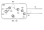
- the predetermined area is the standby position WP and loading of the loading area LPA, as in the manned vehicle 9 (a), the manned vehicle 9 (b), and the manned vehicle 9 (c) in FIGS. 17 and 18.
- the first determination unit 3C determines whether or not the manned vehicle 9 exists in the predetermined area by comparing the coordinates of the position of the manned vehicle 9 with the coordinates of the position of the predetermined area. To determine whether or not the manned vehicle 9 exists in the predetermined area, the coordinates of the position of the manned vehicle 9 are compared with the coordinates of the standby position WP of the loading area LPA and the coordinates of the loading point LP. May be good. At least one loading point LP is set in the loading field LPA. In this embodiment, two loading points LP are set. The loading point LP is a work point at which the loading operation by the loading machine 7 is carried out.
- the first determination unit 3C determines whether or not there is a manned vehicle 9 waiting for acquisition of the approach command at the standby position WP.
- the determination of whether or not the manned vehicle 9 exists in the standby position WP may be made by comparing the coordinates of the position of the manned vehicle 9 with the coordinates of the standby position WP of the loading area LPA.
- the first determination unit 3C includes the presence or absence of the manned vehicle 9 waiting for the acquisition of the approach command to the loading point LPA.
- the first determination unit 3C determines whether or not the unmanned vehicle 2 exists in the predetermined area by comparing the coordinates of the position of the unmanned vehicle 2 with the coordinates of the position of the predetermined area.
- the allocation execution unit 3D loads the unmanned vehicle 2 or the manned vehicle 9 existing in the predetermined area into at least one loading point LP set in the loading area LPA. Allocate to LPA. Further, the allocation execution unit 3D waits at the entrance of the loading yard LPA when there is no unmanned vehicle 2 or manned vehicle 9 waiting for acquisition of the approach command at the waiting position WP set in the loading yard LPA. A loading point LPA is assigned to the unmanned vehicle 2 or the manned vehicle 9. The allocation execution unit 3D allocates the loading point LP in preference to the unmanned vehicle 2 or the manned vehicle 9 waiting at the entrance of the loading area LPA for the manned vehicle 9 existing in the predetermined area.
- the second determination unit 3E receives the input data of the input device 80 provided in the loading machine 7 via the communication system 4.
- the operator of the loading machine 7 operates the input device 80 to move the unmanned vehicle 2 or the manned vehicle 9 into the loading point LP, and the unmanned vehicle 2 or the manned vehicle 9 to leave the loading point LP.
- the second determination unit 3E determines whether or not to allow the unmanned vehicle 2 or the manned vehicle 9 to enter the loading point LP based on the input data of the input device 80 and the allocation result.
- the second determination unit 3E determines whether to move the unmanned vehicle 2 or the manned vehicle 9 from the loading point LP based on the input data of the input device 80 and the allocation result.
- the identification unit 3F identifies either the unmanned vehicle 2 or the manned vehicle 9 as the transport vehicle at the work site.
- the identification unit 3F identifies either the unmanned vehicle 2 or the manned vehicle 9 as the transport vehicle based on the vehicle data of the unmanned vehicle 2 or the manned vehicle 9.
- Each vehicle of the unmanned vehicle 2 or the manned vehicle 9 includes information capable of discriminating between the unmanned vehicle 2 and the manned vehicle 9 as vehicle data. For example, in association with the information of the unit of the manned vehicle or the unmanned vehicle, the unit A is registered as a manned vehicle, the unit B is an unmanned vehicle, and the like.
- the identification unit 3F identifies either the unmanned vehicle 2 or the manned vehicle 9 as the transport vehicle based on the information capable of discriminating between the unmanned vehicle 2 and the manned vehicle 9. In addition, other methods may be used as long as the information for identifying the vehicle is associated with the information for identifying the unmanned vehicle 2 or the manned vehicle 9.
- the command unit 3G outputs a work command for driving the unmanned vehicle 2 or the manned vehicle 9 to the loading point LP or the standby position WP set in the loading field LPA based on the determination result of the first determination unit 3C. Further, the command unit 3G outputs a work command to the unmanned vehicle 2 or the manned vehicle 9 based on the input data from the input device 80 of the loading machine 7. The command unit 3G outputs a work command to the unmanned vehicle 2 or the manned vehicle 9 based on the determination result of the second determination unit 3E. Further, the command unit 3G outputs a allocation command to the unmanned vehicle 2 or the manned vehicle 9 based on the allocation result of the allocation execution unit 3D.
- the command unit 3G outputs a work command for driving the unmanned vehicle 2 or the manned vehicle 9 to a work point at a predetermined stop position based on the specific result of the specific unit 3F.
- the work point at the stop position is, for example, the loading point LP.
- the work command output to the unmanned vehicle 2 includes a command to drive the unmanned vehicle 2.
- the work command output to the manned vehicle 9 includes guidance data to be output to the notification device 50 of the manned vehicle 9.
- the command to drive the unmanned vehicle 2 is, for example, an approach command to allow the unmanned vehicle 2 to enter the loading point LP, an approach command to allow the unmanned vehicle 2 to enter the standby position WP, or an approach command to move the unmanned vehicle 2 out of the loading point LP. Evacuation order, etc.
- the allocation command output to the unmanned vehicle 2 is, for example, an approach command for the unmanned vehicle 2 to enter the loading point LP, an approach command for the unmanned vehicle 2 to enter the standby position WP, or an approach command for the unmanned vehicle 2 to enter the loading point LP. It is a move-out command to move out.
- the guidance data to be output to the notification device 50 of the manned vehicle 9 is, for example, approach guidance data for notifying an approach command for the manned vehicle 9 to enter the loading point LP, approach guidance data for causing the manned vehicle 9 to enter the standby position WP, and the like. Alternatively, it is the move-out guidance data or the like that notifies the move-out command for moving the manned vehicle 9 out of the loading point LP.
- the allocation command output to the manned vehicle 9 includes the allocation guidance data for notifying the allocation command.
- the allocation guidance data is, for example, data capable of recognizing a work point which is a loading point LP or a standby position WP to be entered by a driver who drives a manned vehicle.
- the command unit 3G transmits a work command to the unmanned vehicle 2 and the manned vehicle 9 via the communication system 4.
- the command unit 3G transmits the allocation command to the unmanned vehicle 2 and the manned vehicle 9 via the communication system 4.
- the control device 30 acquires the travel course data of the unmanned vehicle 2 transmitted from the travel course data generation unit 3A, and controls the travel of the unmanned vehicle 2.
- the control device 30 controls the traveling device 21 of the unmanned vehicle 2 so as to travel according to the traveling course data. Further, the control device 30 controls the traveling of the unmanned vehicle 2 based on the work command transmitted from the command unit 3G.
- the control device 40 controls the notification device 50 based on the allocation command or the work command transmitted from the command unit 3G.
- the notification device 50 operates based on the allocation command or the work command output from the command unit 3G.
- the allocation command output to the manned vehicle 9 includes the allocation guidance data for notifying the allocation command.
- the work command output to the manned vehicle 9 is the approach guidance data for the manned vehicle 9 to enter the loading point LP, the approach guidance data for the manned vehicle 9 to enter the standby position WP, or the manned vehicle 9 from the loading point LP. This is the move-out guidance data to be moved out.
- the control device 40 controls the notification device 50 so that the allocation guidance data, the approach guidance data, and the exit guidance data are output from the notification device 50.
- the notification device 50 notifies the allocation guidance data, the approach guidance data, and the exit guidance data.
- the control device 60 transmits the input data generated by operating the input device 80 to the management device 3.
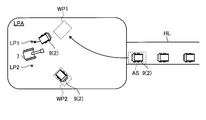
- FIG. 4 is a diagram schematically showing an example of a loading field LPA according to the present embodiment.
- the loading machine 7 operates at the loading site LPA.
- the loading point LP on which the loading operation by the loading machine 7 is carried out is set in the loading site LPA.
- the loading point LP includes a first loading point LP1 which is a first working point and a second loading point LP2 which is a second working point.
- the first loading point LP1 is set on one side of the loading machine 7.
- the second loading point LP2 is set on the other side of the loading machine 7.
- the loading machine 7 with respect to the unmanned vehicle 2 or the manned vehicle 9 existing at the second loading point LP2 after the first loading work for the unmanned vehicle 2 or the manned vehicle 9 existing at the first loading point LP1 is completed. Execute the second loading operation.
- the unmanned vehicle 2 that has entered the first loading point LP1 after the second loading work for the unmanned vehicle 2 or the manned vehicle 9 existing at the second loading point LP2 is completed and the above-mentioned first loading work is completed.
- the first loading operation for the manned vehicle 9 is executed. That is, after the loading work of one of the first loading work and the second loading work is completed, the loading machine 7 executes the other loading work, and the first loading work and the second loading work are performed.
- the so-called double-sided loading work, which repeats the work, is executed.
- the standby position WP waiting for the acquisition of the approach command is set in the loading area LPA.
- the standby position WP includes a first standby position WP1 and a second standby position WP2.
- the first loading point LP1 is associated with the first standby position WP1
- the second loading point LP2 is associated with the second standby position WP2.
- the unmanned vehicle 2 or the manned vehicle 9 for which the allocation command is output stands by at the standby position WP.
- the unmanned vehicle 2 or the manned vehicle 9 waits for the acquisition of the approach command at the standby position WP.
- the approach standby position AS waiting for the acquisition of the allocation command is set at the entrance of the loading area LPA.
- the approach standby position AS is set as a part of the traveling path HL.
- the approach standby position AS may be set inside the loading area LPA.
- the unmanned vehicle 2 or the manned vehicle 9 waits for the acquisition of the allocation command at the approach standby position AS.
- the allocation execution unit 3D is the product to be entered among the first loading point LP1 and the second loading point LP2.
- the allocation process for allocating the spot LP is executed.
- the first determination unit 3C determines whether or not the unmanned vehicle 2 or the manned vehicle 9 waiting for the acquisition of the approach command exists in the standby position WP. When it is determined that the unmanned vehicle 2 or the manned vehicle 9 waiting for the acquisition of the approach command does not exist in the standby position WP, the allocation execution unit 3D executes the allocation process. When the unmanned vehicle 2 or the manned vehicle 9 is waiting at the approach standby position AS, the allocation execution unit allocates the unmanned vehicle 2 or the manned vehicle 9 to the first work point LP1 or the second work point LP2.
- the allocation execution unit 3D performs the first work point LP1. Allocate a manned vehicle 9 to.
- the command unit 3G outputs the allocation command to the manned vehicle 9 based on the result of the allocation process.
- the control device 40 of the manned vehicle 9 controls the notification device 50 based on the allocation command transmitted from the command unit 3G.
- the control device 40 controls the notification device 50 so that the allocation guidance data for notifying the allocation command is output.
- FIG. 5 is a diagram schematically showing an example of the notification device 50 according to the present embodiment.
- FIG. 5 shows an example in which a allocation command for moving the manned vehicle 9 to the first work point LP1 is output.
- the allocation guidance data for causing the manned vehicle 9 to enter the first work point LP1 is displayed on the display device as display data.
- the icon 51A indicating the first standby position WP1 is displayed, and the character data 51B to be traveled to the first standby position WP1 is displayed.
- FIG. 5 is an example. Other display methods may be used as long as the driver of the manned vehicle 9 can be notified that the manned vehicle 9 should travel to the first work point LP1.
- the notification device 50 includes a voice output device, the notification device 50 may be notified by voice.
- the display data of the allocation guidance data has a symbol representing the loading machine 7, a symbol indicating that the unmanned vehicle 2 or the manned vehicle 9 exists at the loading point LP, and a standby position WP of 2. It includes a broken line which is a mark indicating that the vehicle exists in one place, and a double broken line which is a mark indicating the standby position WP where the unmanned vehicle 2 or the manned vehicle 9 should proceed.
- the mark indicating the standby position WP to which the unmanned vehicle 2 or the manned vehicle 9 should advance has a display form different from that of the other standby position WP.
- the mark indicating the standby position WP is the unmanned vehicle 2 Alternatively, it may be a mark that shows the front-rear direction of the manned vehicle 9.
- the second determination unit 3E allocates the product of the first loading point LP1 and the second loading point LP2. An approach determination process for determining whether or not to enter the entry point LP is executed.
- the second determination unit 3E performs the first work on the manned vehicle 9 based on the input data of the input device 80. It is determined whether or not to enter the point LP1. For example, when it is determined that another vehicle that has been performing the loading work at the first work point LP1 has moved out of the first work point LP1 based on the input data of the input device 80, the second determination unit 3E is manned. It is decided to bring the vehicle 9 into the first work point LP1.
- the command unit 3G outputs an approach command to the manned vehicle 9 based on the result of the approach determination process by the second determination unit 3E.
- the control device 40 of the manned vehicle 9 controls the notification device 50 based on the approach command transmitted from the command unit 3G.
- the control device 40 controls the notification device 50 so that the approach guidance data for entering the manned vehicle 9 into the assigned loading point LP is output.
- FIG. 6 is a diagram schematically showing an example of the notification device 50 according to the present embodiment.
- FIG. 6 shows an example in which an approach command for entering the first loading point LP1 is output to the manned vehicle 9.
- approach guidance data for causing the manned vehicle 9 to enter the first loading point LP1 is displayed on the display device as display data.
- the icon 52A indicating the first loading point LP1 is displayed, and the character data 52B to enter the first loading point LP1 is displayed.
- FIG. 6 is an example.
- Other display methods may be used as long as the driver of the manned vehicle 9 can be notified that the manned vehicle 9 should enter the first loading point LP1.
- the notification device 50 includes a voice output device, the notification device 50 may be notified by voice.
- the display device has a symbol representing the loading machine 7, and a display form indicating that the unmanned vehicle 2 or the manned vehicle 9 exists at the loading point LP.
- a certain symbol, a broken line indicating a standby position WP, a double broken line indicating a loading point LP to which the unmanned vehicle 2 or the manned vehicle 9 should advance, and the like are character data 51B and character data that function as guidance. It is displayed together with 52B.
- the display form indicating the standby position WP may be a display form in which the front-rear direction of the unmanned vehicle 2 or the manned vehicle 9 can be seen.
- the notify device 50 includes a display device
- the move-out guidance data for moving the manned vehicle 9 out of the second loading point LP2 is displayed on the display device as display data.
- the notification device 50 includes a voice output device
- the notification device 50 may be notified by voice.
- the notification device 50 includes a light emitting device such as a lamp
- the notification device 50 may be notified by light.
- FIG. 14 is a flowchart showing an example of the management method according to the present embodiment.
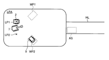
- the loading operation of the unmanned vehicle 2 is executed at the first loading point LP1 and the manned vehicle 9 is waiting at the approach standby position AS. It is specified by the specific unit 3F that the vehicle waiting at the approach standby position AS is a manned vehicle.
- the first determination unit 3C determines whether or not the unmanned vehicle 2 or the manned vehicle 9 waiting for the acquisition of the approach command exists in the standby position WP (step S1).
- step S1 If it is determined in step S1 that there is an unmanned vehicle 2 or a manned vehicle 9 waiting for the acquisition of the approach command at all the standby positions WP (step S1: Yes), the allocation process is not executed.
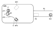
- step S1 when it is determined that there is no unmanned vehicle 2 or manned vehicle 9 waiting for the acquisition of the approach command at at least one standby position WP (step S1: No), the allocation execution unit 3D determines the approach standby position AS. The allocation process is executed for the manned vehicle 9 waiting in (step S2).
- the allocation execution unit 3D allocates the manned vehicle 9 to the second loading point LP2 where the transport vehicle does not exist at the loading point.
- the command unit 3G outputs a allocation command to the manned vehicle 9 waiting at the approach standby position AS (step S3).
- the notification device 50 of the manned vehicle 9 outputs the allocation guidance data as described with reference to FIG.
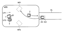
- the driver of the manned vehicle 9 grasps the standby position WP to be moved by the allocation command, and moves the manned vehicle 9 to the second standby position WP2. As shown in FIG. 9, the manned vehicle 9 stands by at the second standby position WP2.
- the driver of the loading machine 7 operates the input device 80 in order to bring the manned vehicle 9 waiting at the second standby position WP2 into the second loading point LP2.
- Examples of the input device 80 include buttons, switches, and a touch panel.
- the driver operates at least one of a button, a switch, and a touch panel to bring the manned vehicle 9 into the second loading point LP2.
- the driver of the loading machine 7 can move the manned vehicle 9 into the second loading point LP2 before moving the unmanned vehicle 2 existing at the first loading point LP1 out of the first loading point LP1. ..
- the second determination unit 3E determines whether or not to allow the manned vehicle 9 to enter the second loading point LP2 based on the input data of the input device 80 (step S4).
- the driver of the loading machine 7 may enter after confirming, for example, that there is no load on the dump body 23 and that there are no obstacles in front of the entering manned vehicle 9. it can.
- step S4 If it is determined in step S4 that the manned vehicle 9 is not allowed to enter the second loading point LP2 (step S4: No), the approach command is not output.
- step S4 When it is determined in step S4 that the manned vehicle 9 is to enter the second loading point LP2 (step S4: Yes), the command unit 3G commands the manned vehicle 9 waiting at the second standby position WP2 to enter. Is output (step S5).
- the manned vehicle 9 waiting at the second standby position WP2 is assigned the second loading point LP2.
- the notification device 50 of the manned vehicle 9 outputs approach guidance data indicating that the vehicle should enter the second loading point LP2 as described with reference to FIG.
- the driver of the manned vehicle 9 causes the manned vehicle 9 to enter the second loading point LP2.
- the manned vehicle 9 enters the second loading point LP2 before the loading work of the first loading point LP1 for the unmanned vehicle 2 is completed.
- the transport vehicle is placed at the second loading point LP2 during the loading work for the transport vehicle at the first loading point LP1.
- the loading operation of the second loading point LP2 on the transport vehicle is immediately executed. As a result, the decrease in productivity at the work site is suppressed.
- the driver of the loading machine 7 operates the input device 80 in order to move the unmanned vehicle 2 from the first loading point LP1.
- the second determination unit 3E determines whether or not to move the unmanned vehicle 2 from the first loading point LP1 based on the input data of the input device 80 (step S6).
- the driver of the loading machine 7 should move out after confirming, for example, that the dump body 23 has been loaded and that there are no obstacles in front of the unmanned vehicle 2 to move out. Can be done.
- step S6 If it is determined in step S6 that the unmanned vehicle 2 is not displaced from the first loading point LP1 (step S6: No), the exit command is not output.
- step S6 When it is determined in step S6 that the unmanned vehicle 2 is to be removed from the first loading point LP1 (step S6: Yes), the command unit 3G outputs an exit command to the unmanned vehicle 2 (step S7). As a result, as shown in FIG. 12, the unmanned vehicle 2 moves out of the first loading point LP1.
- the next manned vehicle 9 arrives at the approach standby position AS.
- the first determination unit 3C determines whether or not there is an unmanned vehicle 2 or a manned vehicle 9 waiting for the acquisition of the approach command (step S1).
- the allocation execution unit 3D executes the allocation process for the manned vehicle 9 waiting at the approach standby position AS (step S2).
- the unmanned vehicle 2 moves to the standby position WP based on the allocation command and the work command from the command unit 3G.
- the unmanned vehicle 2 waiting at the standby position WP enters the allocated loading position LP based on the approach command and enters the assigned loading position LP.
- a new unmanned vehicle 2 is waiting at the approach standby position AS, it moves to the assigned standby position WP based on the allocation command and the work command.
- the driver of the loading machine 7 uses an input device to move the manned vehicle 9 from the second loading point LP2. Operate 80.
- the command unit 3G outputs an exit command to the manned vehicle 9.
- the notification device 50 of the manned vehicle 9 outputs the exit guidance data.
- FIG. 15 is a schematic diagram showing an example of the management method according to the embodiment.
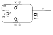
- the unmanned vehicle 2 or the manned vehicle 9 is waiting for the acquisition of the approach command for the first loading point LP1 or the second loading point LP2 at all the standby positions WP. If exists, the allocation execution unit 3D suspends the allocation process.
- the unmanned vehicle 2 or the manned vehicle 9 whose allocation process is suspended stands by outside the loading area LPA.
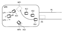
- ⁇ Allocation order> 16 to 18 are schematic views showing an example of the management method according to the embodiment. As shown in FIG. 16, when there are a plurality of unmanned vehicles 2 or manned vehicles 9 waiting at the entrance of the loading yard LPA, the allocation execution unit 3D waits at the entrance of the loading yard LPA. Alternatively, the leading unmanned vehicle 2 or the manned vehicle 9 among the manned vehicles 9 can be assigned to the loading point LP.
- 17 and 18 are schematic views showing an example of a management method when the manned vehicle 9 enters a predetermined area of the loading area.
- the manned vehicle 9 it is assumed that, at the discretion of the driver of the manned vehicle 9, instead of waiting at the entrance of the loading yard LPA as shown in FIG. 16, it enters the loading yard LPA and waits.
- the allocation execution unit 3D exists in the predetermined area of the loading field LPA.
- a predetermined manned vehicle 9 out of a plurality of manned vehicles 9 can be assigned to the loading point LP.
- the allocation execution unit 3D can allocate, for example, a manned vehicle 9 close to the loading point LP among a plurality of manned vehicles 9 existing in a predetermined area to the loading point LP. Therefore, the manned vehicle 9 close to the loading point LP can enter the standby position WP corresponding to the allocated loading point LP.
- the allocation execution unit 3D can allocate a predetermined manned vehicle 9 among the plurality of manned vehicles 9 to the loading point LP. ..
- the allocation execution unit 3D can allocate, for example, the manned vehicle 9 that has entered the loading area LPA first to the loading point LP.
- the manned vehicle 9 that entered first means a manned vehicle 9 having a long waiting time. Therefore, the manned vehicle 9 that has entered the loading area LPA first can enter the standby position WP corresponding to the assigned loading point.
- the manned vehicle allocated to the loading point LP is not limited to the manned vehicle close to the loading point LP or the manned vehicle that first entered the loading point LPA, and the manned vehicle 9 selected under the predetermined conditions is allocated. It should be.
- the allocation execution unit 3D determines the loading area LPA more than the vehicle waiting at the approach standby position AS. It is preferable to give priority to the vehicles existing in the area and allocate the loading points. Further, the number of manned vehicles 9 existing in the predetermined area may be one.
- FIG. 19 is a block diagram showing an example of the computer system 1000.
- the computer system 1000 includes a processor 1001 such as a CPU (Central Processing Unit), a main memory 1002 including a non-volatile memory such as a ROM (Read Only Memory) and a volatile memory such as a RAM (Random Access Memory). It has a storage 1003 and an interface 1004 including an input / output circuit.
- the functions of the management device 3, the control device 30, the control device 40, and the control device 60 described above are stored as programs in the storage 1003.
- the processor 1001 reads the program from the storage 1003, expands it into the main memory 1002, and executes the above-described processing according to the program.
- the program may be distributed to the computer system 1000 via the network.
- the program can execute the computer system 1000 to output a work command to the unmanned vehicle 2 and the manned vehicle 9 based on the input data from the work machine operating at the work site according to the above-described embodiment.
- the command unit 3G outputs a work command to the unmanned vehicle 2 and the manned vehicle 9 based on the input data from the loading machine 7.
- the procedure for loading work on the unmanned vehicle 2 and the procedure for loading work on the manned vehicle 9 can be made the same. Since the procedure for loading work on the unmanned vehicle 2 and the procedure for loading work on the manned vehicle 9 are the same, it is possible to suppress an increase in the burden on the operator who operates the loading machine 7. Therefore, the decrease in work efficiency of the loading work is suppressed.
- the operator of the loading machine 7 can enter the unmanned vehicle 2 or the manned vehicle 9 into the loading point LP by operating the input device 80.
- the procedure for the operator of the loading machine 7 to operate the input device 80 is the same both when the unmanned vehicle 2 is entered into the loading point LP and when the manned vehicle 9 is entered. Further, the operator of the loading machine 7 can move the unmanned vehicle 2 or the manned vehicle 9 out of the loading point LP by operating the input device 80.
- the procedure for the operator of the loading machine 7 to operate the input device 80 is the same both when the unmanned vehicle 2 is removed from the loading point LP and when the manned vehicle 9 is removed. Since the procedure for loading work on the unmanned vehicle 2 and the procedure for loading work on the manned vehicle 9 are the same, it is possible to suppress an increase in the burden on the operator who operates the loading machine 7. Therefore, the decrease in work efficiency of the loading work is suppressed.
- At least a part of the function of the control device 30, the function of the control device 40, and the function of the control device 60 may be provided in the management device 3, or at least a part of the function of the management device 3 may be provided.
- the control device 30, the control device 40, and the control device 60 may be provided.
- the travel course data is generated in the management device 3, and the unmanned vehicle 2 travels according to the travel course data transmitted from the management device 3.
- the control device 30 of the unmanned vehicle 2 may generate travel course data. That is, the control device 30 may have a traveling course data generation unit 3A. Further, each of the management device 3 and the control device 30 may have a travel course data generation unit 3A.
- the control device 60 determines to transmit the input data generated by operating the input device 80 to the management device 3.
- the control device 60 may transmit input data to the unmanned vehicle 2 and the manned vehicle 9 without going through the management device 3. That is, the input data may be transmitted from the loading machine 7 to the unmanned vehicle 2 and the manned vehicle 9 by vehicle-to-vehicle communication.
- the unmanned vehicle 2 is a dump truck which is a kind of transport vehicle.
- the unmanned vehicle 2 may be a work machine including a work machine such as a hydraulic excavator or a bulldozer.
- the loading machine 7 decides to carry out the loading work based on the operation of the operator who boarded the operation room of the loading machine 7.
- the loading machine 7 may be operated remotely. When the loading machine 7 is remotely controlled, the operator does not have to board the operation room of the loading machine 7.
- a work command or the like is output in the double-sided loading operation in which the loading points LP are set on both sides of the loading machine 7.
- a work command or the like may be output.
- the allocation execution unit 3D may be omitted.
- steps S4 and S6 are executed, but one or both of steps S4 and S6 may not be executed as necessary.
- the approach command or the exit command may be output to the unmanned vehicle 2 or the manned vehicle 9 based on the input data generated by the operation of the input device 80 by the driver of the loading machine 7.
- the allocation execution unit 3D allocates the first loading point LP1 as the first working point and the second loading point LP2 as the second working point, but the first working point is the first.
- One standby position WP1 may be allocated, and a second standby position WP2 may be allocated as a second work point.
- the allocation execution unit 3D may separately output the allocation command to the standby position WP and the allocation command to the loading point LP.
- the loading machine 7 is a hydraulic excavator.
- the loading machine 7 may be, for example, a rope excavator or a wheel loader.
- the work point is the loading point LP set in the loading site LPA.
- the work point may be a soil removal point set in the soil removal site DPA.
- the soil discharge point is a work point where the soil discharge work for the crusher 8 is carried out.
- the work point may be a standby position WP set in the loading site LPA in addition to the loading point LP and the soil discharge point, and may be a preset position.
- the command unit 3G decides to output a work command to the unmanned vehicle 2 and the manned vehicle 9 based on the input data of the input device 80 operated by the operator of the loading machine 7.
- the command unit 3G may output a work command to the unmanned vehicle 2 and the manned vehicle 9 based on the input data of the input device of the soil removal site.
- Wireless communication device 30 ... Control Device, 40 ... control device, 50 ... notification device, 60 ... control device, 70 ... work machine, 71 ... running body, 72 ... swivel body, 80 ... input device, AS ... approach standby position, CP ... course point, CR ... Driving course, PA ... Work place, DPA ... Drainage site, LP ... Loading point, LP1 ... 1st loading point, LP2 ... 2nd loading point, LPA ... Loading area, HL ... Driving path, IS ... Crossing, WP ... Standby position, WP1 ... First standby position, WP2 ... Second standby position.
Landscapes
- Engineering & Computer Science (AREA)
- Mining & Mineral Resources (AREA)
- Business, Economics & Management (AREA)
- Civil Engineering (AREA)
- General Engineering & Computer Science (AREA)
- Structural Engineering (AREA)
- General Physics & Mathematics (AREA)
- Physics & Mathematics (AREA)
- Strategic Management (AREA)
- Human Resources & Organizations (AREA)
- Economics (AREA)
- Life Sciences & Earth Sciences (AREA)
- General Business, Economics & Management (AREA)
- Tourism & Hospitality (AREA)
- Entrepreneurship & Innovation (AREA)
- Theoretical Computer Science (AREA)
- Marketing (AREA)
- Atmospheric Sciences (AREA)
- Agronomy & Crop Science (AREA)
- Marine Sciences & Fisheries (AREA)
- Operations Research (AREA)
- Development Economics (AREA)
- Educational Administration (AREA)
- Game Theory and Decision Science (AREA)
- Animal Husbandry (AREA)
- Quality & Reliability (AREA)
- Health & Medical Sciences (AREA)
- General Health & Medical Sciences (AREA)
- Primary Health Care (AREA)
- Control Of Position, Course, Altitude, Or Attitude Of Moving Bodies (AREA)
- Management, Administration, Business Operations System, And Electronic Commerce (AREA)
- Operation Control Of Excavators (AREA)
- Traffic Control Systems (AREA)
- General Factory Administration (AREA)
Abstract
Description
図1は、本実施形態に係る管理システム1、無人車両2、有人車両9、及び積込機7の一例を模式的に示す図である。無人車両2、有人車両9、及び積込機7のそれぞれは、作業現場において稼働する。実施形態において、作業現場は、鉱山又は採石場である。鉱山とは、鉱物を採掘する場所又は事業所をいう。
無人車両2は、例えば管理装置3から送信された走行コースデータに基づいて、作業現場を走行する。無人車両2は、走行装置21と、走行装置21に支持される車両本体22と、車両本体22に支持されるダンプボディ23と、制御装置30とを備える。
有人車両9は、有人車両9の運転室に搭乗した運転者の運転操作に基づいて、作業現場を走行する。有人車両9は、走行装置21と、車両本体22と、ダンプボディ23と、駆動装置24と、ブレーキ装置25と、操舵装置26と、前輪27F及び後輪27Rを含む車輪27と、位置検出装置28と、無線通信機29と、制御装置40と、通知装置50とを備える。
積込機7は、積込機7の操作室に搭乗した操作者の操作に基づいて、積込作業を実施する。積込機7は、作業機70と、走行体71と、旋回体72と、位置検出装置28と、無線通信機29と、制御装置60と、入力装置80とを有する。作業機70は、ブーム、アーム、及びバケットを含む。
図2は、本実施形態に係る作業現場の一例を模式的に示す図である。無人車両2及び有人車両9は、鉱山の作業場PA及び作業場PAに通じる走行路HLの少なくとも一部を走行する。作業場PAは、積込場LPA及び排土場DPAの少なくとも一方を含む。走行路HLは、例えば交差点ISを含む。
図3は、本実施形態に係る管理システム1の一例を示す機能ブロック図である。管理システム1は、管理装置3と、制御装置30と、制御装置40と、制御装置60とを含む。
図4は、本実施形態に係る積込場LPAの一例を模式的に示す図である。図4に示すように、積込場LPAにおいて積込機7が稼働する。積込機7による積込作業が実施される積込点LPが積込場LPAに設定される。本実施形態において、積込点LPは、第1作業点である第1積込点LP1及び第2作業点である第2積込点LP2を含む。第1積込点LP1は、積込機7の一方側に設定される。第2積込点LP2は、積込機7の他方側に設定される。積込機7は、第1積込点LP1に存在する無人車両2又は有人車両9に対する第1積込作業が終了した後、第2積込点LP2に存在する無人車両2又は有人車両9に対する第2積込作業を実行する。第2積込点LP2に存在する無人車両2又は有人車両9に対する第2積込作業が終了した後、上述の第1積込作業が終了した後に第1積込点LP1に進入した無人車両2又は有人車両9に対する第1積込作業を実行する。すなわち、積込機7は、第1積込作業及び第2積込作業の一方の積込作業が終了した後、他方の積込作業を実行し、それら第1積込作業と第2積込作業とを繰り返す、所謂、両側積込作業を実行する。
図7から図13は、本実施形態に係る管理方法の一例を示す模式図である。図14は、本実施形態に係る管理方法の一例を示すフローチャートである。
図15は、実施形態に係る管理方法の一例を示す模式図である。上述の実施形態において、図15に示すように、全ての待機位置WPにて第1積込点LP1又は第2積込点LP2に対する進入指令の取得を待機している無人車両2又は有人車両9が存在する場合、割振実行部3Dは、割振処理を保留する。割振処理を保留されている無人車両2又は有人車両9は、積込場LPAの外側で待機する。
図16から図18は、実施形態に係る管理方法の一例を示す模式図である。図16に示すように、積込場LPAの入口において待機する複数の無人車両2又は有人車両9が存在する場合、割振実行部3Dは、積込場LPAの入口において待機する複数の無人車両2又は有人車両9のうち先頭の無人車両2又は有人車両9を積込点LPに割り振ることができる。
図19は、コンピュータシステム1000の一例を示すブロック図である。上述の管理装置3、制御装置30、制御装置40、及び制御装置60のそれぞれは、コンピュータシステム1000を含む。コンピュータシステム1000は、CPU(Central Processing Unit)のようなプロセッサ1001と、ROM(Read Only Memory)のような不揮発性メモリ及びRAM(Random Access Memory)のような揮発性メモリを含むメインメモリ1002と、ストレージ1003と、入出力回路を含むインターフェース1004とを有する。上述の管理装置3、制御装置30、制御装置40、及び制御装置60のそれぞれの機能は、プログラムとしてストレージ1003に記憶されている。プロセッサ1001は、プログラムをストレージ1003から読み出してメインメモリ1002に展開し、プログラムに従って上述の処理を実行する。なお、プログラムは、ネットワークを介してコンピュータシステム1000に配信されてもよい。
以上説明したように、本実施形態によれば、指令部3Gは、積込機7からの入力データに基づいて、無人車両2及び有人車両9に作業指令を出力する。これにより、無人車両2に対する積込作業の手順と有人車両9に対する積込作業の手順とを同一にすることができる。無人車両2に対する積込作業の手順と有人車両9に対する積込作業の手順とが同一なので、積込機7を操作する操作者の負担が大きくなることが抑制される。したがって、積込作業の作業効率の低下が抑制される。
上述の実施形態において、制御装置30の機能、制御装置40の機能、及び制御装置60の機能の少なくとも一部が管理装置3に設けられてもよいし、管理装置3の機能の少なくとも一部が、制御装置30、制御装置40、及び制御装置60に設けられてもよい。
Claims (4)
- 無人車両と有人車両とが混在して稼働する作業現場で稼動する作業機械からの入力データに基づいて、前記無人車両及び前記有人車両に作業指令を出力する指令部を備える、
作業現場の管理システム。 - 前記有人車両に出力される前記作業指令は、前記有人車両を前記作業現場に設定された作業点に進入させる進入指令を通知する進入案内データ、及び前記有人車両を前記作業点から退去させる退去指令を通知する退去案内データの少なくとも一方を含む、
請求項1に記載の作業現場の管理システム。 - 前記有人車両に設けられ、前記作業指令を通知する通知装置を備える、
請求項1又は請求項2に記載の作業現場の管理システム。 - 無人車両と有人車両とが混在して稼働する作業現場で稼動する作業機械からの入力データに基づいて、前記無人車両及び前記有人車両に作業指令を出力することを含む、
作業現場の管理方法。
Priority Applications (4)
| Application Number | Priority Date | Filing Date | Title |
|---|---|---|---|
| US17/431,492 US20220148424A1 (en) | 2019-04-03 | 2020-04-02 | Management system of work site and management method of work site |
| CA3130286A CA3130286A1 (en) | 2019-04-03 | 2020-04-02 | Management system of work site and management method of work site |
| AU2020251577A AU2020251577A1 (en) | 2019-04-03 | 2020-04-02 | Management system of work site and management method of work site |
| AU2023216835A AU2023216835A1 (en) | 2019-04-03 | 2023-08-17 | Management system of work site and management method of work site |
Applications Claiming Priority (2)
| Application Number | Priority Date | Filing Date | Title |
|---|---|---|---|
| JP2019071671A JP2020170367A (ja) | 2019-04-03 | 2019-04-03 | 作業現場の管理システム及び作業現場の管理方法 |
| JP2019-071671 | 2019-04-03 |
Publications (1)
| Publication Number | Publication Date |
|---|---|
| WO2020204147A1 true WO2020204147A1 (ja) | 2020-10-08 |
Family
ID=72667874
Family Applications (1)
| Application Number | Title | Priority Date | Filing Date |
|---|---|---|---|
| PCT/JP2020/015247 Ceased WO2020204147A1 (ja) | 2019-04-03 | 2020-04-02 | 作業現場の管理システム及び作業現場の管理方法 |
Country Status (5)
| Country | Link |
|---|---|
| US (1) | US20220148424A1 (ja) |
| JP (2) | JP2020170367A (ja) |
| AU (2) | AU2020251577A1 (ja) |
| CA (1) | CA3130286A1 (ja) |
| WO (1) | WO2020204147A1 (ja) |
Families Citing this family (2)
| Publication number | Priority date | Publication date | Assignee | Title |
|---|---|---|---|---|
| WO2023074968A1 (ko) * | 2021-10-29 | 2023-05-04 | 주식회사 기원테크 | 골재운반 차량의 무인 진출입 관리 장치 |
| CN118622372A (zh) * | 2023-03-08 | 2024-09-10 | 卡特彼勒公司 | 用于实现无人矿卡进入和离开作业点的方法和控制装置 |
Citations (5)
| Publication number | Priority date | Publication date | Assignee | Title |
|---|---|---|---|---|
| JP2000339029A (ja) * | 1999-05-31 | 2000-12-08 | Komatsu Ltd | 車両の干渉防止装置 |
| WO2016051524A1 (ja) * | 2014-09-30 | 2016-04-07 | 日立建機株式会社 | 運転支援システム、車両、運転支援端末装置、及び運転支援プログラム |
| WO2016056677A1 (ja) * | 2015-10-30 | 2016-04-14 | 株式会社小松製作所 | 鉱山の管理システム及び鉱山の管理方法 |
| JP2016153987A (ja) * | 2015-02-20 | 2016-08-25 | 日立建機株式会社 | 交通管制サーバ、車載端末装置及び交通管制システム |
| JP2016218576A (ja) * | 2015-05-15 | 2016-12-22 | 日立建機株式会社 | 管制サーバ及び交通管制システム |
Family Cites Families (3)
| Publication number | Priority date | Publication date | Assignee | Title |
|---|---|---|---|---|
| JP6247983B2 (ja) * | 2014-03-31 | 2017-12-13 | 日立建機株式会社 | 車両走行システム及び管制サーバ |
| WO2015151291A1 (ja) * | 2014-04-04 | 2015-10-08 | 日立建機株式会社 | 交通管制サーバ及びシステム |
| JP6498542B2 (ja) * | 2015-06-17 | 2019-04-10 | 日立建機株式会社 | 管制制御システム及び車載端末装置 |
-
2019
- 2019-04-03 JP JP2019071671A patent/JP2020170367A/ja active Pending
-
2020
- 2020-04-02 WO PCT/JP2020/015247 patent/WO2020204147A1/ja not_active Ceased
- 2020-04-02 US US17/431,492 patent/US20220148424A1/en not_active Abandoned
- 2020-04-02 CA CA3130286A patent/CA3130286A1/en active Pending
- 2020-04-02 AU AU2020251577A patent/AU2020251577A1/en not_active Abandoned
-
2023
- 2023-07-18 JP JP2023116973A patent/JP2023126541A/ja active Pending
- 2023-08-17 AU AU2023216835A patent/AU2023216835A1/en not_active Abandoned
Patent Citations (5)
| Publication number | Priority date | Publication date | Assignee | Title |
|---|---|---|---|---|
| JP2000339029A (ja) * | 1999-05-31 | 2000-12-08 | Komatsu Ltd | 車両の干渉防止装置 |
| WO2016051524A1 (ja) * | 2014-09-30 | 2016-04-07 | 日立建機株式会社 | 運転支援システム、車両、運転支援端末装置、及び運転支援プログラム |
| JP2016153987A (ja) * | 2015-02-20 | 2016-08-25 | 日立建機株式会社 | 交通管制サーバ、車載端末装置及び交通管制システム |
| JP2016218576A (ja) * | 2015-05-15 | 2016-12-22 | 日立建機株式会社 | 管制サーバ及び交通管制システム |
| WO2016056677A1 (ja) * | 2015-10-30 | 2016-04-14 | 株式会社小松製作所 | 鉱山の管理システム及び鉱山の管理方法 |
Also Published As
| Publication number | Publication date |
|---|---|
| JP2020170367A (ja) | 2020-10-15 |
| US20220148424A1 (en) | 2022-05-12 |
| AU2023216835A1 (en) | 2023-09-07 |
| CA3130286A1 (en) | 2020-10-08 |
| AU2020251577A1 (en) | 2021-09-16 |
| JP2023126541A (ja) | 2023-09-07 |
Similar Documents
| Publication | Publication Date | Title |
|---|---|---|
| US10394250B2 (en) | Work machine management apparatus | |
| US10591917B2 (en) | Work machine management apparatus | |
| JP6325655B2 (ja) | 交通管制サーバ及びシステム | |
| US10946794B2 (en) | Work machine management system, work machine control system, and work machine | |
| AU2025270981A1 (en) | Management system of work site and management method of work site | |
| JP7246132B2 (ja) | 作業現場の管理システム及び作業現場の管理方法 | |
| JP2023126541A (ja) | 作業現場の管理システム及び作業現場の管理方法 | |
| AU2020240270B2 (en) | Work site management system and work site management method | |
| US11099578B2 (en) | Work machine management system | |
| AU2023233137A1 (en) | System of controlling unmanned vehicle and method of controlling unmanned vehicle | |
| JP2017199395A (ja) | 作業機械の管理方法 | |
| JP2019139809A (ja) | 作業機械の管理装置及び作業機械の管理方法 | |
| JP2020123295A (ja) | 無人車両の制御システム及び無人車両の制御方法 |
Legal Events
| Date | Code | Title | Description |
|---|---|---|---|
| 121 | Ep: the epo has been informed by wipo that ep was designated in this application |
Ref document number: 20781775 Country of ref document: EP Kind code of ref document: A1 |
|
| ENP | Entry into the national phase |
Ref document number: 3130286 Country of ref document: CA |
|
| ENP | Entry into the national phase |
Ref document number: 2020251577 Country of ref document: AU Date of ref document: 20200402 Kind code of ref document: A |
|
| NENP | Non-entry into the national phase |
Ref country code: DE |
|
| 122 | Ep: pct application non-entry in european phase |
Ref document number: 20781775 Country of ref document: EP Kind code of ref document: A1 |