WO2020204067A1 - 流路デバイス、及び検査システム - Google Patents
流路デバイス、及び検査システム Download PDFInfo
- Publication number
- WO2020204067A1 WO2020204067A1 PCT/JP2020/015007 JP2020015007W WO2020204067A1 WO 2020204067 A1 WO2020204067 A1 WO 2020204067A1 JP 2020015007 W JP2020015007 W JP 2020015007W WO 2020204067 A1 WO2020204067 A1 WO 2020204067A1
- Authority
- WO
- WIPO (PCT)
- Prior art keywords
- flow path
- inlet
- liquid
- flow
- flow paths
- Prior art date
- Legal status (The legal status is an assumption and is not a legal conclusion. Google has not performed a legal analysis and makes no representation as to the accuracy of the status listed.)
- Ceased
Links
Images


Classifications
-
- B—PERFORMING OPERATIONS; TRANSPORTING
- B01—PHYSICAL OR CHEMICAL PROCESSES OR APPARATUS IN GENERAL
- B01L—CHEMICAL OR PHYSICAL LABORATORY APPARATUS FOR GENERAL USE
- B01L3/00—Containers or dishes for laboratory use, e.g. laboratory glassware; Droppers
- B01L3/50—Containers for the purpose of retaining a material to be analysed, e.g. test tubes
- B01L3/502—Containers for the purpose of retaining a material to be analysed, e.g. test tubes with fluid transport, e.g. in multi-compartment structures
- B01L3/5027—Containers for the purpose of retaining a material to be analysed, e.g. test tubes with fluid transport, e.g. in multi-compartment structures by integrated microfluidic structures, i.e. dimensions of channels and chambers are such that surface tension forces are important, e.g. lab-on-a-chip
- B01L3/502715—Containers for the purpose of retaining a material to be analysed, e.g. test tubes with fluid transport, e.g. in multi-compartment structures by integrated microfluidic structures, i.e. dimensions of channels and chambers are such that surface tension forces are important, e.g. lab-on-a-chip characterised by interfacing components, e.g. fluidic, electrical, optical or mechanical interfaces
-
- B—PERFORMING OPERATIONS; TRANSPORTING
- B01—PHYSICAL OR CHEMICAL PROCESSES OR APPARATUS IN GENERAL
- B01L—CHEMICAL OR PHYSICAL LABORATORY APPARATUS FOR GENERAL USE
- B01L3/00—Containers or dishes for laboratory use, e.g. laboratory glassware; Droppers
- B01L3/50—Containers for the purpose of retaining a material to be analysed, e.g. test tubes
- B01L3/502—Containers for the purpose of retaining a material to be analysed, e.g. test tubes with fluid transport, e.g. in multi-compartment structures
- B01L3/5027—Containers for the purpose of retaining a material to be analysed, e.g. test tubes with fluid transport, e.g. in multi-compartment structures by integrated microfluidic structures, i.e. dimensions of channels and chambers are such that surface tension forces are important, e.g. lab-on-a-chip
- B01L3/502723—Containers for the purpose of retaining a material to be analysed, e.g. test tubes with fluid transport, e.g. in multi-compartment structures by integrated microfluidic structures, i.e. dimensions of channels and chambers are such that surface tension forces are important, e.g. lab-on-a-chip characterised by venting arrangements
-
- C—CHEMISTRY; METALLURGY
- C12—BIOCHEMISTRY; BEER; SPIRITS; WINE; VINEGAR; MICROBIOLOGY; ENZYMOLOGY; MUTATION OR GENETIC ENGINEERING
- C12M—APPARATUS FOR ENZYMOLOGY OR MICROBIOLOGY; APPARATUS FOR CULTURING MICROORGANISMS FOR PRODUCING BIOMASS, FOR GROWING CELLS OR FOR OBTAINING FERMENTATION OR METABOLIC PRODUCTS, i.e. BIOREACTORS OR FERMENTERS
- C12M1/00—Apparatus for enzymology or microbiology
-
- C—CHEMISTRY; METALLURGY
- C12—BIOCHEMISTRY; BEER; SPIRITS; WINE; VINEGAR; MICROBIOLOGY; ENZYMOLOGY; MUTATION OR GENETIC ENGINEERING
- C12M—APPARATUS FOR ENZYMOLOGY OR MICROBIOLOGY; APPARATUS FOR CULTURING MICROORGANISMS FOR PRODUCING BIOMASS, FOR GROWING CELLS OR FOR OBTAINING FERMENTATION OR METABOLIC PRODUCTS, i.e. BIOREACTORS OR FERMENTERS
- C12M1/00—Apparatus for enzymology or microbiology
- C12M1/34—Measuring or testing with condition measuring or sensing means, e.g. colony counters
-
- G—PHYSICS
- G01—MEASURING; TESTING
- G01N—INVESTIGATING OR ANALYSING MATERIALS BY DETERMINING THEIR CHEMICAL OR PHYSICAL PROPERTIES
- G01N35/00—Automatic analysis not limited to methods or materials provided for in any single one of groups G01N1/00 - G01N33/00; Handling materials therefor
- G01N35/08—Automatic analysis not limited to methods or materials provided for in any single one of groups G01N1/00 - G01N33/00; Handling materials therefor using a stream of discrete samples flowing along a tube system, e.g. flow injection analysis
-
- G—PHYSICS
- G01—MEASURING; TESTING
- G01N—INVESTIGATING OR ANALYSING MATERIALS BY DETERMINING THEIR CHEMICAL OR PHYSICAL PROPERTIES
- G01N37/00—Details not covered by any other group of this subclass
-
- B—PERFORMING OPERATIONS; TRANSPORTING
- B01—PHYSICAL OR CHEMICAL PROCESSES OR APPARATUS IN GENERAL
- B01L—CHEMICAL OR PHYSICAL LABORATORY APPARATUS FOR GENERAL USE
- B01L2200/00—Solutions for specific problems relating to chemical or physical laboratory apparatus
- B01L2200/02—Adapting objects or devices to another
- B01L2200/026—Fluid interfacing between devices or objects, e.g. connectors, inlet details
- B01L2200/027—Fluid interfacing between devices or objects, e.g. connectors, inlet details for microfluidic devices
-
- B—PERFORMING OPERATIONS; TRANSPORTING
- B01—PHYSICAL OR CHEMICAL PROCESSES OR APPARATUS IN GENERAL
- B01L—CHEMICAL OR PHYSICAL LABORATORY APPARATUS FOR GENERAL USE
- B01L2200/00—Solutions for specific problems relating to chemical or physical laboratory apparatus
- B01L2200/06—Fluid handling related problems
- B01L2200/0605—Metering of fluids
-
- B—PERFORMING OPERATIONS; TRANSPORTING
- B01—PHYSICAL OR CHEMICAL PROCESSES OR APPARATUS IN GENERAL
- B01L—CHEMICAL OR PHYSICAL LABORATORY APPARATUS FOR GENERAL USE
- B01L2200/00—Solutions for specific problems relating to chemical or physical laboratory apparatus
- B01L2200/14—Process control and prevention of errors
- B01L2200/143—Quality control, feedback systems
-
- B—PERFORMING OPERATIONS; TRANSPORTING
- B01—PHYSICAL OR CHEMICAL PROCESSES OR APPARATUS IN GENERAL
- B01L—CHEMICAL OR PHYSICAL LABORATORY APPARATUS FOR GENERAL USE
- B01L2300/00—Additional constructional details
- B01L2300/04—Closures and closing means
-
- B—PERFORMING OPERATIONS; TRANSPORTING
- B01—PHYSICAL OR CHEMICAL PROCESSES OR APPARATUS IN GENERAL
- B01L—CHEMICAL OR PHYSICAL LABORATORY APPARATUS FOR GENERAL USE
- B01L2300/00—Additional constructional details
- B01L2300/08—Geometry, shape and general structure
- B01L2300/0809—Geometry, shape and general structure rectangular shaped
- B01L2300/0816—Cards, e.g. flat sample carriers usually with flow in two horizontal directions
-
- B—PERFORMING OPERATIONS; TRANSPORTING
- B01—PHYSICAL OR CHEMICAL PROCESSES OR APPARATUS IN GENERAL
- B01L—CHEMICAL OR PHYSICAL LABORATORY APPARATUS FOR GENERAL USE
- B01L2300/00—Additional constructional details
- B01L2300/08—Geometry, shape and general structure
- B01L2300/0861—Configuration of multiple channels and/or chambers in a single devices
- B01L2300/0864—Configuration of multiple channels and/or chambers in a single devices comprising only one inlet and multiple receiving wells, e.g. for separation, splitting
-
- B—PERFORMING OPERATIONS; TRANSPORTING
- B01—PHYSICAL OR CHEMICAL PROCESSES OR APPARATUS IN GENERAL
- B01L—CHEMICAL OR PHYSICAL LABORATORY APPARATUS FOR GENERAL USE
- B01L2300/00—Additional constructional details
- B01L2300/08—Geometry, shape and general structure
- B01L2300/0861—Configuration of multiple channels and/or chambers in a single devices
- B01L2300/0883—Serpentine channels
-
- B—PERFORMING OPERATIONS; TRANSPORTING
- B01—PHYSICAL OR CHEMICAL PROCESSES OR APPARATUS IN GENERAL
- B01L—CHEMICAL OR PHYSICAL LABORATORY APPARATUS FOR GENERAL USE
- B01L2300/00—Additional constructional details
- B01L2300/16—Surface properties and coatings
- B01L2300/161—Control and use of surface tension forces, e.g. hydrophobic, hydrophilic
-
- B—PERFORMING OPERATIONS; TRANSPORTING
- B01—PHYSICAL OR CHEMICAL PROCESSES OR APPARATUS IN GENERAL
- B01L—CHEMICAL OR PHYSICAL LABORATORY APPARATUS FOR GENERAL USE
- B01L2400/00—Moving or stopping fluids
- B01L2400/04—Moving fluids with specific forces or mechanical means
- B01L2400/0475—Moving fluids with specific forces or mechanical means specific mechanical means and fluid pressure
- B01L2400/0487—Moving fluids with specific forces or mechanical means specific mechanical means and fluid pressure fluid pressure, pneumatics
Definitions
- the present invention relates to a flow path device and an inspection system.
- Patent Document 1 describes a flat plate-shaped lid substrate, a flat plate-shaped flow path substrate joined to the lid substrate, and a plurality of flow paths provided between the lid substrate and the flow path substrate.
- a flow path device including a plurality of flow paths each having a supply port and a discharge port is disclosed. Further, the plurality of flow paths are formed in a straight line, and are arranged at intervals from each other (that is, arranged so as not to be connected to each other).
- the plurality of flow paths are arranged so as not to be connected to each other, even when a plurality of reactions are performed on the same liquid, the plurality of flow paths can be connected to the plurality of flow paths.
- it is necessary to individually put a predetermined liquid through each supply port of a plurality of flow paths it takes time and effort to store the liquid, which is improved from the viewpoint of usability of the flow path device. There was room for.
- the present invention is for solving the above-mentioned problems in the prior art, and an object of the present invention is to provide a flow path device and an inspection system capable of improving usability.
- the flow path device contains a liquid containing a test object used for a biochemical test, a hematology test, a nucleic acid test, or an immunological test.
- a flow path device for the purpose of a main body, a flow path provided inside the main body, and an inlet portion provided so as to be exposed to the outside of the main body and connected to the flow path. There are an inlet portion for allowing the liquid to flow into the flow path through the inlet portion, and an outlet portion provided so as to be exposed to the outside of the main body portion and connected to the flow path.
- the plurality of first flow paths are configured so that the amounts of the liquids are substantially the same, and the magnitude of the positive pressure or negative pressure applied to the liquid in the plurality of first flow paths is less than the threshold value.
- the outflow of the liquid from the first flow path connected to each of the plurality of second flow paths to the reaction chamber portion is restricted, and the magnitude of the applied positive pressure or negative pressure is restricted.
- the plurality of second flow paths are configured so that the outflow of the liquid is allowed when is equal to or higher than the threshold value.
- the flow path device according to claim 2 is the flow path device according to claim 1, wherein the inlet portion is a dispensing opening for dispensing the liquid into the plurality of first flow paths. It is an application opening for applying a positive pressure to the liquid in the plurality of first flow paths.
- the flow path device according to claim 3 has the same hydraulic equivalent diameters of the plurality of first flow paths in the flow path device according to claim 1 or 2, and the lengths of the plurality of first flow paths are the same. The same was made for each.
- the flow path device according to claim 4 has the plurality of first flow paths formed in a meandering shape in the flow path device according to any one of claims 1 to 3.
- the flow path device is the flow path device according to any one of claims 1 to 4, wherein at least a part of the inner wall of the plurality of first flow paths is hydrophilic over the entire length thereof. Must have.
- the flow path device according to claim 6 is the flow path device according to any one of claims 1 to 5, wherein the number of reaction chamber portions connected to each of the plurality of second flow paths is determined. It was a power of 2.
- the flow path device according to claim 7 is the flow path device according to any one of claims 1 to 6, wherein the plurality of second flow paths are connected to at least the first flow path in the inner wall thereof.
- the portion to be formed and the portion connected to the reaction chamber portion have water repellency.
- the flow path device according to claim 8 is the flow path device according to any one of claims 1 to 7, wherein at least a part of the inner wall of the plurality of reaction chambers has hydrophilicity. ..
- the inspection system according to claim 9 includes the flow path device according to any one of claims 1 to 8.
- the flow path is a plurality of first flow paths connected to an inlet portion, and a plurality of first flow paths having hydrophilicity.
- To react the liquid with the flow path and the plurality of second flow paths which are a plurality of second flow paths and each of the plurality of second flow paths is connected to any one of the plurality of first flow paths.
- a positive pressure or a negative pressure When a positive pressure or a negative pressure is applied to the liquid in the path, a plurality of liquids flow out from the plurality of first flow paths toward the corresponding reaction chamber portions so that the amount of the liquid flows out to be substantially the same.
- the first flow path When the magnitude of the positive pressure or negative pressure applied to the liquid in the plurality of first flow paths is less than the threshold value, the first flow path is connected to each of the plurality of second flow paths. A plurality of liquids are restricted from flowing out from the first flow path to the reaction chamber portion, and the outflow of the liquid is allowed when the magnitude of the applied positive pressure or negative pressure is equal to or larger than the threshold value.
- the liquid is primarily dispensed into a plurality of first flow paths via the inlet portion, and a positive pressure or a negative pressure is applied to the primary flow path to apply the liquid.
- a positive pressure or a negative pressure is applied to the primary flow path to apply the liquid.
- the labor of liquid dispensing work can be reduced as compared with the conventional technique (a technique in which a supply port and a discharge port are provided for each of a plurality of flow paths).
- the plurality of first flow paths can be configured so that the amounts of the liquids flowing out from the plurality of first flow paths are substantially the same, the liquids flow out evenly to the plurality of reaction chamber portions. It is possible to realize quantitative dispensing to a plurality of reaction chamber portions.
- a plurality of second flow paths can be configured so that the outflow of liquid is allowed when the size is equal to or larger than the threshold value, and a fixed amount to a plurality of reaction chambers is provided regardless of the number of first flow paths installed. Note can be made reliably. From the above, it is possible to improve the usability of the flow path device.
- the inlet portion is a dispensing opening for dispensing the liquid into the plurality of first flow paths, and the liquid in the plurality of first flow paths is used. Since it is an application opening for applying a positive pressure, it is possible to dispense the liquid or apply the positive pressure through the inlet portion, and as compared with the case where the dispensing opening and the application opening are individually provided, the liquid can be dispensed. It is possible to reduce the labor of dispensing work and applying positive pressure.
- the plurality of first channels are the same.
- the amount of liquid flowing out of the flow paths can be made substantially the same, and when positive pressure or negative pressure is applied to the liquids in the plurality of first flow paths, the applied positive pressure or negative pressure can be used.
- the sizes can be made substantially the same, and it becomes easy to realize quantitative dispensing to a plurality of reaction chamber portions.
- the first flow path device since the plurality of first flow paths are formed in a meandering shape, the first flow path can be made compact and the capacity can be increased. It becomes easier to improve usability.
- the plurality of first flow paths are hydrophilic. It can be reliably held, and the functions of the plurality of first flow paths can be reliably exerted.
- the number of reaction chamber portions connected to each of the plurality of second flow paths is a power of 2, it is connected to each of the plurality of second flow paths.
- the liquid can be evenly flowed into the reaction chambers to be formed, and it becomes easy to realize quantitative dispensing into a plurality of reaction chambers.
- the plurality of second flow paths in the plurality of second flow paths, at least a portion of the inner wall that connects to the first flow path and a portion that connects to the reaction chamber portion have water repellency. Therefore, the plurality of second flow paths can have water repellency, and unnecessary inflow of liquid from the first flow path to the second flow path and backflow of liquid from the reaction chamber portion to the second flow path. And can be reliably restricted.
- the plurality of reaction chamber portions can have hydrophilicity. Therefore, since the reaction chamber portion is a place where a desired reaction is carried out with respect to the liquid as a sample, and since the liquid is usually an aqueous medium, the liquid can be flowed into the reaction chamber portion to carry out the desired reaction. ..
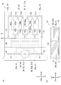
- FIG. 1 It is a figure which shows the flow path device which concerns on Embodiment 1 of this invention, (a) is a plan view, (b) is a front view. It is a figure which shows the state which removed the lid part of the flow path device of FIG. 1, (a) is a plan view, (b) is a sectional view taken along the line AA of (a). It is a front view which shows the state which the pipette tip is inserted into the flow path device of FIG. 2, and the temperature control part is attached. It is a figure which shows the injection process of the inspection method which concerns on Embodiment 1, and is the top view which shows the state which injected the liquid into the 1st flow path on each inlet side (partially not shown).
- Embodiments generally relate to flow path devices and testing systems for containing fluids containing test objects used for biochemical testing, hematology testing, nucleic acid testing, or immunological testing.
- the "biochemical test” means a test in which a component in a sample such as blood is measured by using a colorimetric method, a turbidity measurement method, an enzyme method, an enzyme activity method, or the like.
- the items measured by this "biochemical test” are optional, but for example, AST, ALT, and ⁇ -GT for liver function tests, LDL cholesterol, HDL cholesterol, and triglyceride for lipid tests, and diabetes. Examples include blood glucose in the test and HbA1c.
- the "hematological test” means a test for performing a qualitative test and quantification of mainly blood cell components and plasma components in blood.
- the items measured by this "hematology test” are arbitrary, and examples thereof include red blood cell count, blood pigment amount, white blood cell count, hematocrit, and platelet count.
- the "nucleic acid test” is a test for detecting or quantifying a specific deoxyribonucleic acid (DNA) or ribonucleic acid (RNA) in a sample.
- DNA deoxyribonucleic acid
- RNA ribonucleic acid
- the "immunity test” means a test for measuring or detecting a component in a sample such as urine or blood by using an antigen-antibody reaction.
- Examples of the type of "immunological test” applicable to the present invention include a neferometry method, an immunoturbidimetric method, an aggregation method and the like.
- the items measured by the "immunity test” are arbitrary, and examples thereof include pathogens or viruses of infectious diseases, or antibodies against them, hormones, cancer markers, autoantibodies, and the like.
- test targets used for biochemical tests, hematology tests, nucleic acid tests, or immunological tests serum, plasma, whole blood, blood cell components, urine, stool, sputum, spinal fluid, oral mucosa, etc.
- examples include pharyngeal mucosa, intestinal mucosa, vaginal mucosa and biopsy samples (eg, Fineneedle aspiration (FNA) samples, intestinal samples, liver samples).
- a treated sample obtained by treating these with an acid, an alkali, a protein denaturant, a surfactant, an oxidizing agent, a reducing agent, an enzyme, a dilution, filtration, extraction, heating, concentration, etc., or a combination thereof can be mentioned. ..
- the "liquid containing the inspection target” may be the inspection target itself, or may be a mixture of the inspection target and a solid, semi-solid, liquid substance or the like other than the inspection target.
- test system is a system that performs a biochemical test, a hematology test, a nucleic acid test, or an immunological test on the liquid discharged from the pipette tip to the flow path device, which will be described later.
- the test system is a system used for nucleic acid testing based on the real-time PCR method
- the flow path device is a processed sample subjected to DNA extraction processing and a reagent for real-time PCR (DNA polymerase). , DNTP, primers, fluorescently labeled probes, etc.
- the "real-time PCR method” is a kind of PCR method for amplifying DNA or RNA, and is a method for monitoring and analyzing in real time while amplifying DNA or RNA. Further, examples of the “real-time PCR method” include an intercalation method using a fluorescent substance or an electrochemical substance, a hybridization method using a fluorescently labeled probe, a turbidity detection method, an electric detection method, and the like. In the embodiment, the hybridization method, particularly the TaqMan® method, will be described.
- the first embodiment is a form in which the first flow path and the second flow path are arranged at substantially the same height position.
- the X direction in FIG. 1 is the left-right direction of the flow path device 10 described later (the ⁇ X direction is the left direction of the flow path device 10 and the + X direction is the right direction of the flow path device 10), and the Y direction in FIG.
- the front-back direction of the flow path device 10 (+ Y direction is the front direction of the flow path device 10, -Y direction is the rear direction of the flow path device 10), and the Z direction in FIG. 1 is the vertical direction of the flow path device 10 (+ Z direction).
- the upward direction of the flow path device 10 and the ⁇ Z direction are referred to as the downward direction of the flow path device 10).
- the inspection system 1 includes a flow path device 10 and a temperature control unit 90 shown in FIG. 3, a discharge suction unit (not shown), an attachment / removal unit (not shown), a detection unit (not shown), and a detection unit (not shown). It is equipped with a control unit (not shown).
- each of the discharge suction part, the attachment / removal part, the temperature control part 90, the detection part, and the control unit are connected. It is electrically connected via wiring (not shown). This makes it possible to directly or indirectly perform communication or power supply between the discharge / suction unit, the attachment / extraction unit, the temperature control unit 90, or the detection unit and the control unit.
- the flow path device 10 is for accommodating a liquid L (hereinafter referred to as "liquid L") containing an inspection target (for example, a processed sample containing DNA obtained by processing a biological sample). , Is provided on an installation surface (not shown). The details of the configuration of the flow path device 10 will be described later.
- the discharge / suction unit is a discharge / suction means for discharging and sucking a liquid L or a gas (for example, air) through a pipette tip 11 (for example, a pipette tip made of a resin material or a glass material).
- This discharge / suction unit is configured by using, for example, a known dispensing device for inspection (for example, a dispensing device including a nozzle and a pump (not shown)), and is provided in the vicinity of the flow path device 10. ..
- the attachment / removal unit is an attachment / removal means for attaching / detaching the lid 80 of the flow path device 10 described later to / from the main body 20 of the flow path device 10 described later.
- This mounting / taking-out portion is configured by using, for example, a known chuck mechanism for inspection (for example, a mobile chuck mechanism), and is provided in the vicinity of the flow path device 10.
- the detection unit is a detection means for detecting a target component contained in the liquid L contained in the flow path device 10.
- This detection unit is configured by using, for example, a known detection device (for example, a spectrofluorometer), and is provided in the vicinity of the flow path device 10.
- the temperature control unit 90 is a temperature control means for directly or indirectly heating or cooling the flow path device 10, and a plurality of temperature control units 90 are provided in the vicinity of the flow path device 10. Specifically, as shown in FIG. , It is provided at the upper position, the lower position, or both of the flow path device 10 (in the illustrated example, it is provided only at the lower position).
- the specific configuration of the temperature control unit 90 is arbitrary, but any of the heating means or cooling means used for a normal real-time PCR reaction, such as a Peltier element, an oil bath, and air, can be used.
- the flow path device 10 is configured by using a Peltier element capable of directly heating and cooling the flow path device 10.
- the control unit is a unit that controls each unit of the inspection system 1, and includes an operation unit, a communication unit, an output unit, a power supply unit, a control unit, and a storage unit (all of which are not shown).
- the communication unit is a communication means for communicating with each other with the discharge / suction unit, the attachment / extraction unit, the temperature control unit 90, or the detection unit.
- the output unit is an output means that outputs various information based on the control of the control unit, and is configured by using, for example, a known display means or audio output means.
- the power supply unit supplies power supplied from a commercial power source or a battery (for example, a battery, etc.) to each part of the control unit, and also supplies power to the discharge / suction unit, the attachment / extraction unit, the temperature control unit 90, or the detection unit. It is a means.
- the control unit is a control means for controlling each part of the control unit.
- this control unit includes a CPU, various programs that are interpreted and executed on the CPU (including a basic control program such as an OS, and an application program that is started on the OS and realizes a specific function) and programs.
- It is a computer configured with an internal memory such as a RAM for storing various types of data.
- the storage unit is a storage means for storing programs and various data necessary for the operation of the control unit, and is configured by using a known rewritable recording medium.
- a non-volatile recording medium such as a flash memory may be used. it can.
- the flow path device 10 includes a main body portion 20, an inlet portion 30, an outlet portion 40, a flow path 50, and a lid portion 80.
- the main body 20 is a basic structure of the flow path device 10, and includes a first main body 21, an upper second main body 22, and a lower second main body 23, as shown in FIGS. 1 to 3. There is.
- the first main body portion 21 is a part of the basic structure of the main body portion 20 and has a flow path 50.
- the first main body portion 21 is formed in a substantially plate shape (in the illustrated example, it is formed in a plate shape having a rectangular shape in a plane shape and a substantially L shape in a side surface shape). , As shown in FIG. 1, are provided substantially horizontally.
- the size of the first main body 21 can be arbitrarily set as long as the flow path 50 can be accommodated, but in the illustrated example, it is set as follows. That is, as shown in FIG. 1, the length of the first main body 21 in the left-right direction is set longer than the length of the flow path 50 in the left-right direction, and the length of the first main body 21 in the front-rear direction is set. , Set longer than the length of the flow path 50 in the front-rear direction. In the illustrated example, the vertical length of the first main body 21 is substantially the same as the vertical length of the flow path 50.
- the upper second main body 22 and the lower second main body 23 are other parts of the basic structure of the main body 20 and close the open surface of the flow path 50.
- the upper second main body 22 and the lower second main body 23 are formed separately from the first main body 21 and are formed in a thin layer shape (specifically, a rectangle). It is attached to the main side surface of the first main body portion 21 (the side surface having the largest area among the side surfaces of the first main body portion 21), which is formed of a rectangular thin film.
- the upper second main body 22 is attached to the upper surface of the first main body 21 by adhesion or welding
- the lower second main body 23 is the first main body. It is attached to the lower surface of the portion 21 by adhesion or welding.
- the sizes of the upper second main body 22 and the lower second main body 23 can be arbitrarily set as long as the open surface of the flow path 50 can be closed, but in the illustrated example, they are as follows. It is set. That is, as shown in FIG. 1, the lengths of the upper second main body 22 and the lower second main body 23 in the left-right direction are set to be substantially the same as the lengths of the first main body 21 in the left-right direction.
- the length of each of the upper second main body 22 and the lower second main body 23 in the front-rear direction is set to be substantially the same as the length of the first main body 21 in the front-rear direction.
- the length of each of the lower second main body 23 in the vertical direction is set shorter than the length of the first main body 21 in the vertical direction.
- the material of the flow path device 10 is not particularly limited, but for example, when used for real-time PCR, a translucent material (transparent material) is used in order to detect fluorescence. Is preferable.
- a translucent material transparent material
- examples of such materials include polypropylene, polystyrene, polyethylene, polycarbonate, acrylic resin (polymethyl methacrylate (PMMA)), cyclic olefin resin (cycloolefin polymer (COP), cyclic olefin copolymer (COC)), and silicone resin (PDMS), polyethylene terephthalate (PET), resin materials such as photosensitive epoxy resin (SU-8), glass and the like.
- a material having less autofluorescence it is preferable to use a material having less autofluorescence.
- a cyclic olefin resin, a cyclic olefin copolymer, or quartz glass can be preferably used.
- a cyclic olefin resin, polyofylene, or the like, which is a water-repellent material is used as the material of the flow path device 10.
- the main body 20 configured in this way, the main body 20 can be easily configured even when the configuration of the flow path 50 is complicated, and the manufacturability of the flow path device 10 can be improved.
- the inlet portion 30 is an opening for allowing the liquid L to flow into the flow path 50 through the inlet portion 30, and the outlet portion 40 causes the air in the flow path 50 to flow out through the outlet portion 40.
- the inlet portion 30 and the outlet portion 40 are each formed in a circular shape, and are provided so as to be exposed to the outside of the main body portion 20.
- the inlet portion 30 is provided over the first main body portion 21 and the upper second main body portion 22 on the left side portion of the main body portion 20, and the flow path 50 (specifically, the upstream side of the flow path 50). It is connected to the end).
- the outlet portion 40 is provided on the left side of the main body portion 20 over the first main body portion 21 and the upper second main body portion 22, and the flow path 50 (specifically, the downstream end of the flow path 50). Part) is connected.
- the method of installing the inlet portion 30 and the outlet portion 40 is arbitrary, but in the example shown in FIG. 2, the inlet portion 30 and the outlet portion 40 are concentric (specifically, concentric when viewed from the plane direction). It is arranged so that the center point of the entrance portion 30 is located directly below the center point of the exit portion 40.
- the diameters of the inlet portion 30 and the outlet portion 40 are arbitrary, but in the example shown in FIG. 2, the diameter of the inlet portion 30 is outside the tip portion of the pipette tip 11 for injecting the liquid L. It is set to be larger than the diameter and smaller than the maximum outer diameter of the pipette tip 11.
- the pipette tip 11 is usually configured so that the outer diameter of the tip portion having the suction / discharge port is the smallest, and the outer diameter gradually increases as the distance from the tip portion increases. Therefore, when the pipette tip 11 is inserted into the inlet portion 30, the outer peripheral portion of the pipette tip 11 is described later without contacting the downstream end portion of the first flow path side connecting portion 61a described later. It comes into contact with the inner wall of the first flow path side connecting portion 61a.
- the present invention is not limited to this, and for example, the diameter of the inlet portion 30 may be equal to or larger than the diameter of the outlet portion 40.
- the flow path 50 fluidly accommodates the liquid L discharged from the pipette tip 11.
- This flow path 50 is formed as a hollow portion (for example, a square columnar hollow portion), and is provided inside the main body portion 20 as shown in FIG. 1, and is provided inside the main body portion 20 and is provided on the inlet side flow path 60 and the outlet side. It is provided with a flow path 70.
- the inlet side flow path 60 is a flow path located on the inlet portion 30 side of the portion of the flow path 50, and is a flow path for accommodating the liquid L.
- the inlet-side flow path 60 is provided inside the first main body 21, and has a first inlet-side flow path 60a located on the center side and a first inlet. It is provided with a second inlet side flow path 60b located on the front side of the portion side flow path 60a and a third inlet side flow path 60c located on the rear side of the first inlet side flow path 60a. ..
- the configurations of the first inlet side flow path 60a, the second inlet side flow path 60b, and the third inlet side flow path 60c are substantially the same, and therefore, in the following, the first inlet Only the configuration of the part-side flow path 60a will be described.
- the first inlet-side flow path 60a includes an inlet-side first flow path 61, an inlet-side second flow path 62, and reaction chamber portions 63a and 63b.
- reaction chamber portion 63 When it is not necessary to distinguish the reaction chamber portions 63a and 63b, they are simply collectively referred to as "reaction chamber portion 63".
- the above-mentioned “inlet side first flow path 61” corresponds to the "first flow path” in the claims
- the above-mentioned “inlet side second flow path 62” corresponds to the "first flow path” in the claims. Corresponds to "two channels”.
- the inlet-side first flow path 61 is a part of the basic structure of the first inlet-side flow path 60a, and is for primary dispensing the liquid L.
- the inlet side first flow path 61 is provided from the vicinity of the upper end portion to the lower end portion of the first main body portion 21 and is connected to the inlet portion 30, and is connected to the inlet portion 30. It includes 61a and a main body portion 61b on the first flow path side.
- the first flow path side connecting portion 61a is a portion for connecting the inlet portion 30 and the first flow path side main body portion 61b, and as shown in FIG. 1, the first flow path side main body portion from the inlet portion 30 It is arranged so as to project toward the upstream end of 61b and the axial direction of the first flow path side connecting portion 61a is along the left-right direction. Further, in the illustrated example, the first flow path side connection portion 61a is formed so as to also serve as the first flow path side connection portion 61a of the second inlet side flow path 60b and the third inlet side flow path 60c.
- the present invention is not limited to this, and the second inlet side flow path 60b or the third inlet side flow path 60c may be formed separately from the first flow path side connection portion 61a.
- the first flow path side main body portion 61b is a basic structure of the inlet portion side first flow path 61, and as shown in FIG. 1, the first flow path side connection portion 61a is connected to the inlet side from the downstream end portion.
- the two flow paths 62 are arranged so as to project toward the upstream end portion and the axial direction of the first flow path side main body portion 61b is horizontal. The details of the configuration of the inlet side first flow path 61 will be described later.
- the inlet side second flow path 62 is another part of the basic structure of the first inlet side flow path 60a, and connects the inlet side first flow path 61 and the reaction chamber portions 63a and 63b. Is for.
- the inlet-side second flow path 62 is provided at a position on the right side of the first inlet-side flow path 60a from the vicinity of the upper end portion to the lower end portion of the first main body portion 21. (That is, it is arranged at a height position substantially the same as the first inlet side flow path 60a), and includes a second flow path side first connection portion 62a and a second flow path side second connection portion 62b.
- the second flow path side first connection portion 62a is the inlet side first flow path 61 (that is, any one of the plurality of inlet side first flow paths 61) of the first inlet side flow path 60a. Is a portion connected to the reaction chamber portion 63a, and is formed so that the planar shape is curved (for example, substantially L-shaped) as shown in FIG. 1, and the first flow path 61 on the inlet side is formed. It is connected to the downstream end of the reaction chamber portion 63a and the upstream end of the reaction chamber portion 63a.
- the second connection portion 62b on the second flow path side is the first flow path 61 on the inlet side of the first inlet side flow path 60a (that is, any one of the plurality of first flow paths 61 on the inlet side) and the reaction chamber. It is a portion connected to the portion 63b, and is formed so that the planar shape is curved (for example, substantially inverted L-shaped) as shown in FIG. 1, and is downstream of the first flow path 61 on the inlet side. It is connected to the side end portion and the upstream side end portion of the reaction chamber portion 63b.
- the reaction chamber portions 63a and 63b are other parts of the basic structure of the first inlet side flow path 60a and are for reacting the liquid L.
- the reaction chamber portions 63a and 63b are formed so that the planar shape is linear along the left-right direction, respectively, and as shown in FIG. 1, at a position on the right side of the inlet side second flow path 62.
- the first main body 21 is provided from the upper end to the lower end (that is, each is formed as a through hole).
- the outlet side flow path 70 is a flow path located on the outlet portion 40 side of the portion of the flow path 50, and is a flow path for allowing the air in the flow path 50 to flow out to the outside.
- the outlet side flow path 70 is provided inside the first main body 21, and has a first outlet side flow path 70a located on the front side and a first outlet. It is provided with a second outlet side flow path 70b located on the rear side of the part side flow path 70a.
- the configurations of the first outlet side flow path 70a and the second outlet side flow path 70b are substantially the same. Therefore, in the following, the configuration of the first outlet portion side flow path 70a Only will be described.
- the first outlet side flow path 70a is the outlet side first flow path 71a, 71b, 71c, the outlet side second flow path 72, and the outlet side third flow.
- a road 73, a fourth flow path 74 on the outlet side, a fifth flow path 75 on the exit side, and a fifth flow path 76 on the exit side are provided.
- the outlet-side first flow paths 71a, 71b, 71c are a part of the basic structure of the first outlet-side flow path 70a, and the first inlet-side flow path 60a (specifically, the reaction chamber portion). It is a portion connected to 63a) and the first inlet side flow path 60b (specifically, reaction chamber portions 63a and 63b).
- These outlet-side first flow paths 71a, 71b, and 71c are each formed so that the planar shape is linear along the left-right direction, and as shown in FIG. 1, the first inlet-side flow path 60a. And at a position on the right side of the first inlet side flow path 60b, they are provided at the lower end of the first main body 21 and the vicinity thereof, respectively.
- the outlet side first flow path 71a is connected to the downstream end of the reaction chamber portion 63a of the first inlet side flow path 60a, and the outlet side first flow path 71b is on the first inlet side.
- the flow path 60b is connected to the downstream end of the reaction chamber portion 63b, and the outlet side first flow path 71c is connected to the downstream end of the reaction chamber portion 63a of the first inlet side flow path 60b.
- the outlet-side second flow path 72 is another part of the basic structure of the first outlet-side flow path 70a, and is a portion connected to the outlet-side first flow path 71a, 71b, 71c. ..
- the outlet side second flow path 72 is formed so that the plane shape becomes a straight line along the front-rear direction, and as shown in FIG. 1, at a position on the right side of the outlet side second flow path 72. It is provided at the lower end of the first main body 21 and its vicinity, and is connected to the downstream end of each of the outlet-side first flow paths 71a, 71b, and 71c.
- the outlet portion side third flow path 73 is another part of the basic structure of the first outlet portion side flow path 70a, and is a portion connected to the outlet portion side second flow path 72.
- the outlet side third flow path 73 is formed so that the planar shape is linear along the left-right direction, and as shown in FIG. 1, at a position in front of the exit side second flow path 72, It is provided at the lower end of the first main body 21 and its vicinity, and is connected to the downstream end of the outlet-side second flow path 72.
- the outlet portion side fourth flow path 74 is another part of the basic structure of the first outlet portion side flow path 70a, and is a portion connected to the outlet portion side third flow path 73.
- the outlet side fourth flow path 74 is formed so that the side surface shape is linear along the vertical direction, and as shown in FIG. 1 (b), is on the left side of the outlet side third flow path 73. At the position, it is provided from the lower end to the upper end of the first main body 21 (that is, formed as a through hole), and is connected to the downstream end of the third flow path 73 on the outlet side.
- the outlet portion side fifth flow path 75 is another part of the basic structure of the first outlet portion side flow path 70a, and is a portion connected to the outlet portion side fourth flow path 74.
- the outlet side fifth flow path 75 is formed so that the plane shape becomes a straight line along the front-rear direction, and as shown in FIG. 1, at a position behind the exit side fourth flow path 74. , Is provided at the upper end of the first main body 21 and its vicinity, and is connected to the downstream end of the outlet side fourth flow path 74.
- the outlet portion side sixth flow path 76 is another part of the basic structure of the first outlet portion side flow path 70a, and is a portion connected to the outlet portion side fifth flow path 75 and the outlet portion 40. is there.
- the outlet side sixth flow path 76 is formed so that the side surface shape is linear along the vertical direction, and as shown in FIG. 1 (b), is behind the outlet side fifth flow path 75. At the position of, it is provided from the outlet portion 40 to the inlet portion 30 of the first main body portion 21, and is connected to the downstream end portion and the outlet portion 40 of the fifth flow path 75 on the outlet portion side.
- the outlet side sixth flow path 76 is formed so as to also serve as the outlet side sixth flow path 76 of the second outlet side flow path 70b.
- the present invention is not limited to this, and the second outlet side flow path 70b may be formed separately from the outlet side sixth flow path 76. The details of the configuration of the outlet side flow path 70 will be described later.
- the lid portion 80 is for opening and closing the inlet portion 30 and the outlet portion 40.
- the inlet portion 30 and the outlet portion 40 can be opened and closed together by one lid portion 80.
- the lid portion 80 is formed in a truncated cone shape, and is arranged so as to be inserted into the fifth flow path 75 on the outlet portion side via the outlet portion 40.
- the shape and size of the lid 80 are arbitrary, but in the illustrated example, they are set as follows. That is, as shown in FIG. 1, the side surface shape of the lid portion 80 is set to a substantially truncated cone shape in which the length of the upper end portion is larger than the length of the lower end portion. Further, the planar shape of the lid portion 80 is set to a substantially circular shape. Further, the diameter of the lid portion 80 is set to a size that allows the entire lid portion 80 to be in close contact with the outlet portion 40 when the lid portion 80 is inserted into the fifth flow path 75 on the outlet portion side. The minimum diameter of the lid 80 is set smaller than the diameter of the outlet 40, and the maximum diameter of the lid 80 is set larger than the diameter of the outlet 40. Further, the vertical length of the lid portion 80 is set to be shorter (or substantially the same) than the vertical length of the fifth flow path 75 on the outlet portion side.
- a material having excellent heat resistance and chemical resistance, and having appropriate flexibility (or rigidity) and elasticity capable of sealing the outlet portion 40 can be preferably used.
- silicone rubber, butyl rubber, nitrile rubber, natural rubber, synthetic natural rubber, butadiene rubber, styrene butadiene rubber, ethylene propylene rubber, chloroprene rubber, acrylic rubber, chlorosulfonated polyethylene rubber, urethane rubber, fluororubber, etc. can be mentioned.
- the inlet side flow path 60 (Details of the structure of the flow path on the inlet side) Next, the details of the configuration of the inlet side flow path 60 will be described.
- the features of the inlet side flow path 60 (specifically, the features of the inlet side first flow path 61 and the inlet side second flow path 62) are as shown below in the illustrated example.
- each inlet side first flow path 61 has hydrophilicity, and the liquid L in each inlet side first flow path 61 is positively or negatively pressured by a predetermined method. Is applied (specifically, a positive pressure or a negative pressure is applied to the liquid L so that the liquid L in the first flow path 61 on each inlet side flows out toward the corresponding reaction chamber portion 63.
- the amount of liquid L flowing out from each inlet side first flow path 61 toward the corresponding reaction chamber portion 63 is configured to be substantially the same.
- hydrophilic as used herein means a state in which the solid surface is easily wetted with water, and specifically, a state in which the water contact angle is less than 90 degrees.
- water repellency means a state in which the water contact angle exceeds 90 degrees. The “water contact angle” referred to here is measured by a method according to JIS R 3257: 1999.
- each inlet-side first flow path 61 has hydrophilicity over its entire length (specifically, the total length in the axial direction). More specifically, of the inner wall of each inlet side first flow path 61, the portion on the first main body 21 side has hydrophilicity over its entire length, and the inner wall of each inlet side first flow path 61.
- the portion of the lower second main body 23 side is formed of a hydrophilic film over its entire length.
- the present invention is not limited to this, for example, the portion on the side of the first main body 21 has hydrophilicity, and the portion on the side of the lower second main body 23 is formed of a water-repellent film (made of a water-repellent material such as polypropylene).
- the film may be formed, or the portion on the side of the first main body 21 is not hydrophilic and the portion on the side of the lower second main body 23 is formed of a hydrophilic film. May be good.
- “having hydrophilicity” can be achieved, for example, by hydrophilizing the solid surface of a desired portion.
- each inlet side first flow path 61 can have hydrophilicity, so that when the liquid L is injected into the inlet side flow path 60 via the inlet portion 30, each inlet side first flow path 61 can have hydrophilicity.
- the liquid L can be evenly (specifically, at an equal flow rate) flow into the first flow path 61 on each inlet side by the capillary force acting on the one flow path 61.
- the plurality of inlet-side first flow paths 61 can surely have hydrophilicity, and the functions of the plurality of inlet-side first flow paths 61 can be surely exhibited.
- the shape of the first flow path 61 on each inlet side is set as follows. That is, the shape of the first flow path side connection portion 61a of each inlet side first flow path 61 is set to be linear as shown in FIG. However, the present invention is not limited to this, and for example, it may be set in a curved shape. Further, the shape of the first flow path side main body portion 61b of each inlet side first flow path 61 is set to be curved, and specifically, the inlet side first flow path 61 is made compact and accommodated. In order to increase the amount, as shown in FIG. 1, the shape of the downstream portion of the first flow path side main body portion 61b is set to meander. However, the present invention is not limited to this, and for example, it may be set in a curved shape other than the meandering shape, or may be set in a straight line shape.
- the size of the first flow path 61 on the inlet side is as follows so that the capacity of the first flow path 61 on the inlet side is substantially the same as the capacity of the corresponding reaction chamber 63. Is set to. That is, with respect to the hydraulic power equivalent diameter of each inlet side first flow path 61 (the diameter of the equivalent circular pipe when replaced with a circular pipe equivalent to a flow path having an arbitrary cross-sectional shape), each inlet side first flow path 61. The hydraulic equivalent diameters of one flow path 61 are set to be the same.
- the hydraulic equivalent diameters of the first flow path side connection portion 61a and the first flow path side main body portion 61b of each inlet side first flow path 61 are set to be substantially the same as the diameter of the inlet portion 30. (However, the present invention is not limited to this, and the diameter may be set smaller or larger than the diameter of the inlet portion 30). Further, the length (length in the axial direction) of each inlet side first flow path 61 is set so that the length of each inlet side first flow path 61 is the same. More specifically, the length of the first flow path side connection portion 61a of each inlet side first flow path 61 is set to be shorter than the length of the first main body portion 21 in the vertical direction.
- the length of the first flow path side main body 61b of each inlet side first flow path 61 is set to about half the length of the first main body 21 in the left-right direction (however, the present invention is not limited to this). , It may be set longer or shorter than half the length of the first main body 21 in the left-right direction).
- the capacity of each inlet side first flow path 61 can be set to be substantially the same as the capacity of the corresponding reaction chamber unit 63.
- the amount of the liquid L flowing out from the plurality of inlet-side first flow paths 61 can be made substantially the same, and the positive pressure or negative pressure with respect to the liquid L in the plurality of inlet-side first flow paths 61 can be made substantially the same. Can be made substantially the same in magnitude of the applied positive pressure or negative pressure when is applied.
- the inlet side first of each of the first inlet side flow path 60a, the second inlet side flow path 60b, and the third inlet side flow path 60c.
- the second flow path on the inlet side is the second.
- the outflow of the liquid L from the first flow path 61 on the inlet side connected to the flow path 62 to the reaction chamber portion 63 is restricted and the magnitude of the applied positive pressure or negative pressure is equal to or greater than the threshold value. It is configured to allow the outflow of liquid L.
- each inlet-side second flow path 62 has water repellency at least in a portion of the inner wall that is connected to the inlet-side first flow path 61 and a portion that is connected to the reaction chamber portion 63.
- the portion of the inner wall of the second flow path 62 on the inlet side on the first main body 21 side is formed of a water-repellent material (for example, a cyclic olefin resin or the like) over its entire length.
- the portion on the lower second main body 23 side is formed of a water-repellent film over its entire length.
- the present invention is not limited to this, and for example, only the portion of the inner wall of each inlet side second flow path 62 that is connected to the inlet side first flow path 61 and the portion that is connected to the reaction chamber portion 63 have water repellency. You may become.
- the plurality of second flow paths 62 on the inlet side can have water repellency, and unnecessary inflow of the liquid L from the first flow path 61 on the inlet side to the second flow path 62 on the inlet side.
- the backflow of the liquid L from the reaction chamber portion 63 to the inlet side second flow path 62 can be reliably restricted.
- the size of the second flow path 62 on each inlet side is set as follows. That is, the hydraulic power equivalent diameter of each inlet side second flow path 62 is set so that the hydraulic power equivalent diameter of each inlet side second flow path 62 is the same, and more specifically, the inlet side. It is set to be substantially the same as the hydraulic equivalent diameter of the first flow path 61 on the portion side (however, it is not limited to this, and may be set smaller or larger than the hydraulic equivalent diameter of the first flow path 61 on the inlet side. ). Further, regarding the length (length in the axial direction) of the second flow path 62 on the inlet side, the length (length in the axial direction) of the second flow path 62 on the inlet side is the same.
- It is set, and more specifically, it is set to a length shorter than the length of the first flow path 61 on the inlet side.
- the liquid L is dispensed into a plurality of inlet-side first flow paths 61 via the inlet portion 30, and a positive pressure or a negative pressure is applied to the dispensed liquid L.
- the liquid L can be discharged to a plurality of reaction chamber portions 63, and the liquid L is dispensed as compared with the conventional technique (a technique in which a supply port and a discharge port are provided for each of a plurality of flow paths). The trouble of can be reduced.
- the plurality of inlet-side first chambers 61 can be configured so that the amounts of the liquids L flowing out from the plurality of inlet-side first chambers 61 are substantially the same, the liquid L can be reacted with a plurality of liquids L. It can flow out evenly to each of the chamber portions 63, and quantitative dispensing to a plurality of reaction chamber portions 63 can be realized. Further, when the magnitude of the positive pressure or the negative pressure applied to the liquid L in the plurality of inlet-side first flow paths 61 is less than the threshold value, the outflow of the liquid L is restricted and the liquid L is applied.
- a plurality of second flow paths 62 on the inlet side can be configured so that the outflow of the liquid L is allowed, and the first flow path 61 on the inlet side can be configured.
- Quantitative dispensing to a plurality of reaction chamber portions 63 can be reliably performed regardless of the number of installations. From the above, it is possible to improve the usability of the flow path device 10.
- the reaction chamber portion 63 connected to each inlet side second flow path 62.
- the number is set to a power of 2.
- the number of the reaction chamber portions 63 is set to two. With such a setting, the liquid L can be evenly flowed into the reaction chamber portions 63 connected to each of the plurality of inlet-side second flow paths 62, and the liquid L can be evenly flowed into the plurality of reaction chamber portions 63. It will be easier to realize the note.
- the present invention is not limited to this, and for example, it may be set to other powers of 2, or as an example, it may be set to two or more (4, 8, etc.), or it may be set to one. You may.
- each reaction chamber portion 63 of the first inlet side flow path 60a, the second inlet side flow path 60b, and the third inlet side flow path 60c is hydrophilic over the entire length.
- the portion of the inner wall of each reaction chamber portion 63 on the upper second main body portion 22 side is formed of a water-repellent material (for example, cyclic olefin resin or the like) over its entire length, and each reaction chamber Of the inner wall of the portion 63, a portion on the upper second main body 22 side and a portion on the lower second main body 23 side are formed of a hydrophilic film over the entire length thereof.
- the present invention is not limited to this, for example, the portion of the inner wall of each reaction chamber portion 63 on the side of the first main body portion 21 is subjected to the hydrophilic treatment, and the upper second main body portion of the inner wall of each reaction chamber portion 63
- the portion on the 22 side and the portion on the lower second main body portion 23 side may be formed of a hydrophilic film.
- the reaction chamber portion 63 can have hydrophilicity. Therefore, since the reaction chamber portion 63 is a place where a desired reaction is carried out with the liquid L as a sample, and the liquid L is usually an aqueous medium, the liquid L is allowed to flow into the reaction chamber portion 63 to be desired. The reaction can be carried out.
- the sizes of the reaction chambers 63 of the first inlet side flow path 60a, the second inlet side flow path 60b, and the third inlet side flow path 60c are as follows in the illustrated example. It is set according to the street. That is, the hydraulic power equivalent diameters of the reaction chamber portions 63 are set so that the hydraulic power equivalent diameters of the second flow paths 62 on the inlet portion side are the same, and specifically, the second flow on the inlet portion side. It is set to be larger than the hydraulic power equivalent diameter of the road 62 (however, not limited to this, it may be set to be equal to or smaller than the hydraulic power equivalent diameter of the second flow path 62 on the inlet side). Further, the length (length in the axial direction) of each reaction chamber portion 63 is set so that the length of each reaction chamber portion 63 is the same. Specifically, the first inlet side first. The length is set shorter than the length of the flow path 61.
- each of the first outlet side flow path 70a and the second outlet side flow path 70b is at least the inlet side flow path 60 of the inner wall thereof.
- the connecting portion has water repellency.
- the portion on the first main body 21 side is a water-repellent material (for example, a cyclic olefin system) over its entire length.
- the portion of the inner wall on the lower second main body 23 side is formed of a water-repellent film over its entire length.
- the present invention is not limited to this, and for example, only the portion of the inner wall connected to the inlet side flow path 60 may be formed of the water-repellent material.
- the outlet side flow path 70 can have water repellency, and the air in the inlet side flow path 60 can flow out to the outside while suppressing the liquid L from flowing into the outlet side flow path 70. ..
- the air in the first inlet side flow path 60a and the first inlet side flow path 60b is taken. It can be set arbitrarily as long as it can be leaked to the outside, but in the first embodiment, it is set as follows. That is, of the first outlet-side first flow path 71, the outlet-side second flow path 72, and the outlet-side third flow path 73 of the first outlet-side flow path 70a and the second outlet-side flow path 70b, respectively.
- the hydraulic equivalent diameter is set smaller than the hydraulic equivalent diameter of the reaction chamber portion 63.
- outlet-side fourth flow path 74 of each of the first outlet-side flow path 70a and the second outlet-side flow path 70b is set to be larger than the hydraulic power equivalent diameter of the outlet-side third flow path 73. (However, the present invention is not limited to this, and the diameter may be set to be equal to or less than the hydraulic power equivalent diameter of the third flow path 73 on the outlet side). Further, the outlet-side fifth flow path 75 of each of the first outlet-side flow path 70a and the second outlet-side flow path 70b is set to be smaller than the hydraulic power equivalent diameter of the outlet-side fourth flow path 74.
- the diameter may be set to be equal to or less than the hydraulic power equivalent diameter of the fourth flow path 74 on the outlet side).
- the length (axial length) of each of the outlet-side sixth flow path 76 of the first outlet-side flow path 70a and the second outlet-side flow path 70b the outlet-side fifth flow path. It is set larger than the hydraulic power equivalent diameter of 75, and more specifically, as shown in FIG. 1 (b), the hydraulic power equivalent diameter of the 6th flow path 76 on the outlet side is set larger as it approaches the outlet 40. are doing.
- each of the first outlet side flow path 70a and the second outlet side flow path 70b is set to be longer than the length in the left-right direction of the main body portion 20. (However, the length is not limited to this, and the length of the main body 20 in the left-right direction may be set or less).
- the inspection method according to the first embodiment includes an injection step, an amplification step, and a detection step.
- the premise of this inspection method is as follows. That is, it is assumed that the flow path device 10 is preassembled. In addition, different analysis items are included in the reaction chamber portions 63 of the first inlet side flow path 60a, the second inlet side flow path 60b, and the third inlet side flow path 60c in the flow path device 10. It is assumed that the corresponding reagents for real-time PCR (for example, DNA polymerase, dNTP, primer, TaqMan® probe, etc.) (including one or more sets of different primers) are pre-contained. Further, as shown in FIG. 3, it is assumed that the flow path device 10 is installed horizontally in contact with the temperature control unit 90.
- each part of the inspection system 1 is performed by the control device.
- the control device by introducing substantially the same amount of liquid L, which is the same sample, into the plurality of reaction chamber portions 63, it is possible to simultaneously carry out a plurality of types of real-time PCR on the same sample. More preferably, by having different reagents for multiplex real-time PCR in each reaction chamber portion 63, it becomes possible to perform a larger number of kinds of real-time PCR.
- the reagent present in the reaction chamber portion 63 is not limited to the reagent for real-time PCR, and may be a reagent for biochemical test, hematology test, immunological test, or other nucleic acid test.
- the injection step is a step of injecting the liquid L into the flow path device 10.
- the pipette tip 11 attached to the nozzle of the discharge suction unit sucks the liquid L, and then the nozzle and the pipette tip 11 are moved above the inlet portion 30 of the flow path device 10, and then the pipette.
- the chip 11 is moved downward and inserted into the inlet-side first flow path 61 of the inlet-side flow path 60 via the inlet portion 30.
- the liquid L is discharged through the inlet portion 30 to the first inlet side flow path. Injection is performed into the first flow path 61 on the inlet side of each of the 60a, the second inlet side flow path 60b, and the third inlet side flow path 60c.
- This predetermined amount is arbitrary, but for example, the reaction chamber portions 63 of the first inlet side flow path 60a, the second inlet side flow path 60b, and the third inlet side flow path 60c are almost full. It may be set to a certain amount.
- the first on the inlet side since the magnitude of the positive pressure applied to the liquid L in the first flow path 61 on the inlet side with the injection of the liquid L is less than the threshold value, the first on the inlet side.
- the corresponding inlet-side second flow path 62 from the first flow path 61 limits the outflow of liquid L from each inlet-side first flow path 61 to the corresponding reaction chamber portion 63.
- the pipette tip 11 is removed from the flow path device 10 by moving the nozzle of the discharge suction unit upward and then in the horizontal direction.
- the inlet portion 30 is a dispensing opening for dispensing the liquid L into the plurality of inlet-side first flow paths 61, and the liquid L is relative to the liquid L in the plurality of inlet-side first flow paths 61. Since it is an application opening for applying a positive pressure, the liquid L can be dispensed and the positive pressure can be applied through the inlet portion 30, as compared with the case where the dispensing opening and the application opening are individually provided. , It is possible to reduce the labor of dispensing the liquid L and applying the positive pressure.
- the amplification step is a step for amplifying the target sequence of DNA (or RNA) contained in the liquid L contained in each reaction chamber portion 63 after the injection step.
- the detection step is a step for detecting the target sequence of the amplified DNA after or during the amplification step.
- the amplification step and the detection step are carried out in parallel.
- the lid 80 of the flow path device 10 is inserted into the fifth flow path 75 on the outlet side via the outlet 40 using a mounting take-out portion or the like. As a result, in the illustrated example, the outlet portion 40 and the inlet portion 30 are collectively closed by the lid portion 80.
- the liquid L contained in the flow path device 10 (particularly, the liquid L in the reaction chamber 63) is generated due to the temperature control and DNA amplification. Detects fluorescence. Nucleic acid amplification is carried out by performing temperature control in a cycle of denaturation temperature (about 95 ° C.)-annealing temperature (about 50-75 ° C.) -extension temperature (about 60-75 ° C.).
- the detailed denaturation temperature, annealing temperature and extension temperature, and retention time of each temperature are adjusted and set in advance according to the template DNA, primer sequence, and target sequence.
- the temperature cycle is usually carried out about 25 to 50 times.
- the disposal step is a step of discarding the flow path device 10 after the amplification step and the detection step.
- the liquid L in the flow path device 10 can be used for later analysis, but the flow path device 10 is discarded together without opening the lid 80. Since the large amount of nucleic acid after the amplification reaction can be prevented from diffusing into the environment by an aerosol or the like because it can be discarded without opening the lid 80, the risk of contamination with other unreacted test solutions can be reduced. In particular, in a nucleic acid amplification test in which a target sequence of DNA is amplified several million times, it can be said that the effect of reducing the risk of contamination is great.
- the nucleic acid amplification test can be automatically performed by the test system 1, and the nucleic acid amplification test can be easily performed.
- the flow path 50 is the plurality of inlet-side first flow paths 61 connected to the inlet portion 30, and the plurality of inlet-side first flow paths 61 having hydrophilicity.
- a plurality of inlets each of which is a plurality of inlet-side second flow paths 62, and each of the plurality of inlet-side second flow paths 62 is connected to any one of the plurality of inlet-side first flow paths 61.
- the second flow path 62 on the part side and the plurality of reaction chambers 63 for reacting the liquid L, and each of the plurality of reaction chambers 63 is one of the plurality of second flow paths 62 on the inlet side.
- a plurality of connected reaction chamber portions 63 are provided, and when a positive pressure or a negative pressure is applied to the liquid L in the plurality of inlet-side first flow paths 61 by a predetermined method, the plurality of inlet portions are provided.
- a plurality of inlet side first flow paths 61 are configured so that the amount of liquid L flowing out from the side first flow path 61 toward the corresponding reaction chamber portion 63 is substantially the same, and a plurality of inlet portions are formed.
- the outflow of the liquid L from the side first flow path 61 to the reaction chamber portion 63 is restricted so that the outflow of the liquid L is allowed when the magnitude of the applied positive pressure or negative pressure is equal to or greater than the threshold value. Since the plurality of inlet-side second flow paths 62 are configured, the liquid L is dispensed into the plurality of inlet-side first flow paths 61 via the inlet 30, and the liquid L is dispensed. By applying positive pressure or negative pressure, the liquid L can be discharged to a plurality of reaction chamber portions 63, as compared with the conventional technique (a technique in which a supply port and a discharge port are provided for each of a plurality of flow paths). The labor of dispensing the liquid L can be reduced.
- the plurality of inlet-side first chambers 61 can be configured so that the amounts of the liquids L flowing out from the plurality of inlet-side first chambers 61 are substantially the same, the liquid L can be reacted with a plurality of liquids L. It can flow out evenly to each of the chamber portions 63, and quantitative dispensing to a plurality of reaction chamber portions 63 can be realized. Further, when the magnitude of the positive pressure or the negative pressure applied to the liquid L in the plurality of inlet-side first flow paths 61 is less than the threshold value, the outflow of the liquid L is restricted and the liquid L is applied.
- a plurality of inlet-side second chambers 62 can be configured so that the outflow of the liquid L is allowed when the magnitude of the positive pressure or the negative pressure is equal to or greater than the threshold value. Quantitative dispensing to a plurality of reaction chamber portions 63 can be reliably performed regardless of the number of installations. From the above, it is possible to improve the usability of the flow path device 10.
- the inlet portion 30 is a dispensing opening for dispensing the liquid L into the plurality of inlet-side first flow paths 61, and the liquid L is provided with respect to the liquid L in the plurality of inlet-side first flow paths 61. Since it is an application opening for applying a positive pressure, the liquid L can be dispensed or the positive pressure can be applied through the inlet portion 30, and compared with the case where the dispensing opening and the application opening are individually provided. It is possible to reduce the labor of dispensing the liquid L and applying the positive pressure.
- the plurality of inlet-side first channels 61 are the same.
- the amount of the liquid L flowing out from the flow path 61 can be made substantially the same, and when a positive pressure or a negative pressure is applied to the liquid L in the plurality of inlet-side first flow paths 61, the liquid L is applied.
- the magnitudes of the positive pressure and the negative pressure can be made substantially the same, and it becomes easy to realize quantitative dispensing to a plurality of reaction chamber portions 63.
- the first flow paths 61 on the inlet side are formed in a meandering shape, the first flow paths 61 on the inlet side can be made more compact and the capacity can be increased, and the usability of the flow path device 10 can be increased. It becomes easy to raise.
- the plurality of inlet-side first flow paths 61 since at least a part of the inner wall of the plurality of inlet-side first flow paths 61 has hydrophilicity over the entire length thereof, the plurality of inlet-side first flow paths 61 surely have hydrophilicity. This makes it possible to reliably exert the functions of the plurality of inlet-side first flow paths 61.
- the number of reaction chamber portions 63 connected to each of the plurality of inlet side second flow paths 62 is a power of 2, they are connected to each of the plurality of inlet side second flow paths 62.
- the liquid L can be evenly flowed into the reaction chamber portion 63, and it becomes easy to realize quantitative dispensing into a plurality of reaction chamber portions 63.
- a plurality of inlet-side second flow paths 62 can have water repellency, unnecessary inflow of liquid L from the first flow path to the inlet-side second flow path 62, and inlet from the reaction chamber portion 63.
- the backflow of the liquid L to the second flow path 62 on the part side can be reliably restricted.
- the plurality of reaction chamber portions 63 can have hydrophilicity. Therefore, since the reaction chamber portion 63 is a place where a desired reaction is carried out with the liquid L as a sample, and the liquid L is usually an aqueous medium, the liquid L is allowed to flow into the reaction chamber portion 63 to be desired. The reaction can be carried out.
- the second embodiment is a form in which the first flow path and the second flow path are arranged at different height positions.
- the configuration of the second embodiment is substantially the same as the configuration of the first embodiment unless otherwise specified, and the configuration substantially the same as the configuration of the first embodiment is used in the first embodiment. If necessary, the same code and / or name as the one used was added, and the description thereof will be omitted.
- the inspection system 1 according to the second embodiment is configured in substantially the same manner as the inspection system 1 according to the first embodiment.
- the configuration of the flow path device 10 is devised as shown below.
- the main body 20 of the flow path device 10 includes a first main body 21, a film-shaped upper second main body 22, and a lower second main body 23, respectively. It is manufactured as a separate body, and is manufactured by integrating both the upper second main body 22 and the lower second main body 23 with the first main body 21 by adhesion, welding, or the like.
- the side surface on the side to be adhered or welded to the first main body portion 21 has a structure having water repellency as a whole.
- the water repellency of this aspect is achieved by using a water repellent material or by applying a water repellent treatment.
- the side surface to be adhered or welded to the first main body 21 has a structure having hydrophilicity as a whole.
- the hydrophilicity of this aspect is achieved by applying a hydrophilic treatment or by using a hydrophilic material.
- the flow path 50 is formed by providing a predetermined recess and a through hole in the first main body 21 before being integrated with the second main bodies 22 and 23.
- the first inlet flow path 61 is formed as a groove-shaped recess on the lower side surface of the first main body 21.
- the second inlet passage 62 is formed as a groove-shaped recess on the upper side surface of the first main body 21, the first inlet passage 61 and the second inlet passage 62 are different from each other. Can be placed at a height position.
- the connecting portion between the first inlet passage 61 and the second inlet passage 62 is formed as a through hole penetrating from the upper side surface to the lower side surface of the first main body portion 21.
- reaction chamber portion 63 is formed as a through hole
- outlet portion side first flow path 71 is formed as a groove-shaped recess on the upper side surface of the first main body portion 21.
- These flow paths can be formed by closing the grooves and through holes on both sides of the first main body 21 by closing the film-shaped second main bodies 22 and 23.
- the first main body portion 21 having a groove and a through hole can be relatively easily manufactured by injection molding or the like.
- the first inlet flow path 61 is composed of a groove formed on the lower side surface of the first main body 21 and an upper side surface of the lower second main body 23 having hydrophilicity, and is composed of a first inlet flow.
- the road 61 has at least hydrophilicity on the upper side surface portion of the lower second main body portion 23, that is, the lower inner wall of the first inlet portion flow path 61.
- the second inlet flow path 62 is composed of a groove formed on the upper side surface of the first main body portion 21 and a lower side surface of the upper second main body portion 22 having water repellency. There is no hydrophilic portion in the second inlet flow path 62.
- the liquid L is supplied to the plurality of first inlet flow paths 61. Can be uniformly inflowed.
- the water repellency of the inner wall of the second inlet passage 62 and the barrier in the height direction exist, so that the second inlet The inflow of the liquid L into the partial flow path 62 is blocked.
- the first inlet flow path 61 may be formed on the upper side of the first main body 21, and the second inlet flow path 62 may be formed on the lower side of the main body 21, but the height of the connection between the two flow paths is high. Since the effect of the barrier in the vertical direction cannot be obtained, it is preferable to arrange the first inlet flow path 61 on the lower side and the second inlet flow path 62 on the upper side.
- the reaction chamber portion 63 is formed so as to close the through hole provided in the first main body portion 21 with the upper second main body portion 22 and the lower second main body portion 23, at least the lower second main body portion 23 is formed.
- the upper side surface of the portion 23 has hydrophilicity. Therefore, when a positive pressure or a negative pressure is applied to the dispensed liquid L that remains in the first inlet flow path 61, the liquid L that has passed through the second inlet flow path 62 becomes a reaction chamber. It can easily flow into and stay in the portion 63 (secondary dispensing).
- the second inlet flow path 62 and the outlet side first flow path 71 do not have a hydrophilic portion and have a barrier in the height direction, so that backflow and leakage of the liquid L are unlikely to occur. It has become.
- the first flow path 71 on the outlet side may be formed on the lower side of the main body 21, but it is preferably arranged on the upper side because the effect of the barrier in the height direction cannot be obtained.
- the problem to be solved by the invention and the effect of the invention are not limited to the above-mentioned contents, and the present invention solves a problem not described above or an effect not described above. It can also be played, and it may solve only some of the tasks described or play only some of the effects described.
- the inspection system 1 includes a discharge suction unit and a mounting / taking-out part, but the present invention is not limited to this, and for example, at least one of the discharge suction part and the mounting / taking-out part may be used. It may be omitted. In this case, the work of discharging or sucking the liquid L, or the work of attaching or detaching the lid 80 may be performed manually. Alternatively, the discharge suction part and the attachment / removal part may be configured as one.
- first main body 21, the upper second main body 22, and the lower second main body 23 are formed separately, but the present invention is not limited to this, for example.
- a 3D printer or the like may be used to integrally form one or both of the first main body portion 21, the upper second main body portion 22, and the lower second main body portion 23.
- the inlet side first flow path 61, the inlet side second flow path 62, and the reaction chamber portion 63 are integrally formed. It is formed in a groove shape on the first main body 21 and the lower second main body 23.
- a reagent for real-time PCR containing a different primer for each flow path is added to the groove-shaped reaction chamber portion 63, and then the upper second main body portion 22 is attached by adhesion or welding. It is possible to create the main body 20. Further, when the first main body portion 21, the upper second main body portion 22, and the lower second main body portion 23 are integrally formed, for example, a reagent is externally placed in each reaction chamber portion 63 of the flow path device 10.
- an injection part for example, an injection part having an opening or a flow path
- a reagent for real-time PCR containing a different primer is injected for each injection part, and the above
- the flow path device 10 having the same configuration as the above can be created.
- the main body portion 20 includes the upper second main body portion 22 and the lower second main body portion 23, but the present invention is not limited to this.
- the open surface of the flow path 50 is formed only on either the upper surface or the lower surface of the first main body 21, either the upper second main body 22 or the lower second main body 23 is formed. May be omitted.
- the inlet portion 30 and the outlet portion 40 have been described as being arranged concentrically, but the present invention is not limited to this, and the inlet portion 30 and the outlet portion 40 may be arranged concentrically.
- the inlet portion 30 and the outlet portion 40 may be arranged so as to partially overlap each other.
- the inlet portion 30 and the outlet portion 40 may be arranged adjacent to each other so as not to overlap each other.
- the inlet portion 30 and the outlet portion 40 can be integrally closed by one lid portion 80.
- the present invention is not limited to this, and for example, the inlet portion 30 and the outlet portion 40 may be arranged apart from each other in the left-right direction or the front-rear direction of the flow path device 10.
- each inlet side first flow path 61 has a plurality of first flow path side connection portions 61a connected to any one of two or more inlet portions 30, and a plurality of first flow path sides.
- a first flow path side main body portion 61b connected to each of the connection portions 61a may be provided.
- the number of outlets 40 installed is one, but the number is not limited to this, and for example, two or more may be installed.
- the first outlet side flow path 70a or the second outlet portion side flow path 70b includes a plurality of outlet portion side fifth flow paths 75 connected to two or more outlet portions 40. May be good.
- the number of inlet portions 30 is preferably one or a small number, but the outlet portion 40 is a flow path when the liquid L is injected into the flow path device 10. Since it is an air vent for pushing out the air or the like in the 50, for example, the same number as the reaction chamber portion 63 may be arranged apart from the inlet portion 30.
- the number of the first flow paths 61 on the inlet side is three, but the number is not limited to this, and may be, for example, two or four or more. You may.
- the number of the inlet side second flow path 62 or the reaction chamber portion 63 may be increased or decreased according to the increase or decrease in the number of the inlet side first flow path 61.
- the hydraulic equivalent diameters of the first flow paths 61 on each inlet side are set to be the same, but the present invention is not limited to this.
- the liquid L in the first flow path 61 on the inlet side when a positive pressure or a negative pressure is applied to the liquid L in the first flow path 61 on the inlet side, the liquid L flows out from the first flow path 61 on the inlet side toward the corresponding reaction chamber 63.
- the hydraulic equivalent diameters of the first flow paths 61 on the inlet side may be different from each other.
- the lengths of the first flow paths 61 on each inlet side are set to be the same, but the present invention is not limited to this.
- the liquid L in the first flow path 61 on the inlet side flows out from the first flow path 61 on the inlet side toward the corresponding reaction chamber 63.
- the lengths of the first flow paths 61 on the inlet side may be different.
- the first flow path 61 on the inlet side is substantially the same as the capacity of the corresponding first flow path 61 on the inlet side.
- the size is not limited to this, and for example, the capacity of each inlet side first flow path 61 is set to be smaller than the capacity of the corresponding reaction chamber 63.
- the size of the first flow path 61 on the inlet side may be set.
- the hydraulic power equivalent diameter of each inlet side first flow path 61 may be set smaller than the hydraulic power equivalent diameter of each inlet side first flow path 61 according to the first embodiment, or each inlet.
- the length of the portion-side first flow path 61 may be set to be shorter than the length of each inlet-side first flow path 61 according to the first embodiment.
- the liquid L is discharged from the nozzle of the discharge suction portion via the pipette tip 11, so that the liquid L is flowed to the side of the first inlet portion via the inlet portion 30. Even if the liquid L is injected with the first flow path 61 on the inlet side of each of the passage 60a, the second inlet side flow path 60b, and the third inlet side flow path 60c, and a positive pressure is applied to the liquid L. Good.
- the lid 80 is formed of a resin columnar body, but the present invention is not limited to this, and for example, a flat thin film-like body (as an example, a resin seal). Etc.) may be formed. Further, when the inlet portion 30 and the outlet portion 40 are arranged apart from each other (a plurality of portions may be arranged), the lid portion 80 may have a shape in which the inlet portion 30 and the outlet portion 40 are closed one by one. , The shape may be closed together.
- An example of the configuration of the lid portion 80 is a film-shaped seal that covers the entire upper surface of the upper second main body portion 22. As the material of the lid 80 in this case, for example, polypropylene or the like can be preferably used.
- the inspection method includes an injection step, an amplification step, and a detection step, but the present invention is not limited to this.
- the flow path device 10 is not assembled or the reagent for real-time PCR is not contained in the reaction chamber portion 63, a preparatory step for performing these operations may be further added.
- the reagents to be contained are not limited to the reagents for real-time PCR, and may be reagents for biochemical tests, hematological tests, immunological tests, or other nucleic acid tests.
- the flow path device 10 is provided with a suction opening connected to each reaction chamber portion 63 via a predetermined flow path, and air is sucked from a nozzle of a suction portion (not shown) through the suction opening. Negative pressure may be applied to the liquid L in the first flow path 61 on the inlet side.
- the magnitude of the negative pressure applied to the liquid L in the first flow path 61 on the inlet side becomes equal to or larger than the threshold value, the corresponding reaction from the first flow path 61 on the inlet side
- the liquid L may be discharged to the chamber portion 63, and the negative pressure may be continuously applied until all the liquid L in the first flow path 61 on the inlet side is discharged.
- the flow path device of Appendix 1 is a flow path device for accommodating a liquid containing a test object used for a biochemical test, a hematology test, a nucleic acid test, or an immunological test, and is a main body portion and the main body portion.
- An inlet portion provided inside and an inlet portion provided so as to be exposed to the outside of the main body portion and connected to the flow path, and the liquid is allowed to flow into the flow path through the inlet portion.
- An inlet portion for the purpose and an outlet portion that is provided so as to be exposed to the outside of the main body portion and is connected to the flow path, in order to allow air in the flow path to flow out through the outlet portion.
- the flow path is a plurality of first flow paths connected to the inlet portion, and is a plurality of hydrophilic first flow paths and a plurality of second flow paths.
- Each of the plurality of second flow paths is a plurality of second flow paths connected to any one of the plurality of first flow paths, and a plurality of reaction chamber portions for reacting the liquid.
- Each of the reaction chamber portions of the above is provided with a plurality of reaction chamber portions connected to any one of the plurality of second flow paths, and is positive with respect to the liquid in the plurality of first flow paths by a predetermined method.
- the plurality of first streams are such that the amounts of the liquids flowing out from the plurality of first channels toward the corresponding reaction chamber portions are substantially the same.
- a path is formed, and when the magnitude of the positive pressure or negative pressure applied to the liquid in the plurality of first flow paths is less than the threshold value, the path is connected to each of the plurality of second flow paths.
- the outflow of the liquid from the first flow path to the reaction chamber portion is restricted, and the outflow of the liquid is allowed when the magnitude of the applied positive pressure or negative pressure is equal to or greater than the threshold value.
- the plurality of second flow paths were configured.
- the flow path device of Appendix 2 is the flow path device according to Appendix 1, wherein the inlet portion is a dispensing opening for dispensing the liquid into the plurality of first flow paths, and the plurality of first channels. It is an application opening for applying a positive pressure to the liquid in one flow path.
- the hydraulic equivalent diameters of the plurality of first flow paths are the same, and the lengths of the plurality of first flow paths are set to be the same. It was made the same.
- the plurality of first flow paths are formed in a meandering shape in the flow path device according to any one of Appendix 1 to 3.
- the flow path device of Appendix 5 is the flow path device according to any one of Supplementary note 1 to 4, wherein at least a part of the inner wall of the plurality of first flow paths has hydrophilicity over the entire length thereof. Become.
- the flow path device of Appendix 6 is the flow path device according to any one of Supplementary note 1 to 5, wherein the number of the reaction chamber portions connected to each of the plurality of second flow paths is a power of 2. And said.
- the flow path device is the flow path device according to any one of the items 1 to 6, wherein the plurality of second flow paths are at least a portion of the inner wall connected to the first flow path and the above.
- the portion connected to the reaction chamber portion has water repellency.
- the flow path device according to the appendix 8 is the flow path device according to any one of the items 1 to 7, wherein at least a part of the inner wall of the plurality of reaction chambers has hydrophilicity.
- the inspection system of Appendix 9 includes the flow path device according to any one of claims 1 to 8.
- the flow path is a plurality of first flow paths connected to the inlet portion, and the plurality of first flow paths having hydrophilicity.
- One flow path is configured and is connected to each of the plurality of second flow paths when the magnitude of the positive pressure or negative pressure applied to the liquids in the plurality of first flow paths is less than the threshold value.
- a plurality of second so as to limit the outflow of the liquid from the first flow path to the reaction chamber portion and allow the outflow of the liquid when the magnitude of the applied positive or negative pressure is equal to or greater than the threshold value.
- the liquid is primarily dispensed into a plurality of first flow paths via the inlet portion, and a plurality of liquids are supplied by applying a positive pressure or a negative pressure to the primary dispensed liquid.
- the liquid can be dispensed into the reaction chamber portion of the above, and the labor of liquid dispensing work can be reduced as compared with the conventional technique (a technique in which a supply port and a discharge port are provided for each of a plurality of flow paths).
- the plurality of first flow paths can be configured so that the amounts of the liquids flowing out from the plurality of first flow paths are substantially the same, the liquids flow out evenly to the plurality of reaction chamber portions.
- a plurality of second flow paths can be configured so that the outflow of liquid is allowed when the size is equal to or larger than the threshold value, and a fixed amount to a plurality of reaction chambers is provided regardless of the number of first flow paths installed. Note can be made reliably. From the above, it is possible to improve the usability of the flow path device.
- the inlet portion is a dispensing opening for dispensing the liquid into the plurality of first flow paths, and is positive with respect to the liquid in the plurality of first flow paths. Since it is an application opening for applying pressure, it is possible to dispense liquid or apply positive pressure through the inlet, and the amount of liquid is as compared to the case where the dispensing opening and the application opening are provided individually. It is possible to reduce the labor of the note work and the work of applying positive pressure.
- the hydraulic equivalent diameters of the plurality of first flow paths are the same, and the lengths of the plurality of first flow paths are the same, so that the plurality of first streams are the same.
- the amount of liquid flowing out of the path can be made substantially the same, and the magnitude of the applied positive pressure or negative pressure when a positive pressure or negative pressure is applied to the liquids in the plurality of first flow paths. These can be made substantially the same, and it becomes easy to realize quantitative dispensing to a plurality of reaction chamber portions.
- the first flow path can be made compact and the capacity can be increased, and the flow path device can be used. It becomes easier to improve the sex.
- the plurality of first flow paths ensure hydrophilicity. It is possible to reliably exert the functions of a plurality of first flow paths.
- the number of reaction chambers connected to each of the plurality of second flow paths is a power of 2
- they are connected to each of the plurality of second flow paths.
- the liquid can be evenly flowed into the reaction chambers, and it becomes easy to realize quantitative dispensing into a plurality of reaction chambers.
- the plurality of second flow paths have water repellency at least in a portion of the inner wall that is connected to the first flow path and a portion that is connected to the reaction chamber portion. Therefore, the plurality of second flow paths can have water repellency, and unnecessary inflow of liquid from the first flow path to the second flow path and backflow of liquid from the reaction chamber portion to the second flow path. Can be reliably restricted.
- the plurality of reaction chamber portions can have hydrophilicity. Therefore, since the reaction chamber portion is a place where a desired reaction is carried out with respect to the liquid as a sample, and the liquid is usually an aqueous medium, the liquid can be flowed into the reaction chamber portion to carry out the desired reaction. ..
Landscapes
- Chemical & Material Sciences (AREA)
- Health & Medical Sciences (AREA)
- Life Sciences & Earth Sciences (AREA)
- General Health & Medical Sciences (AREA)
- Bioinformatics & Cheminformatics (AREA)
- Engineering & Computer Science (AREA)
- Analytical Chemistry (AREA)
- Biochemistry (AREA)
- Wood Science & Technology (AREA)
- Biotechnology (AREA)
- Organic Chemistry (AREA)
- Zoology (AREA)
- Dispersion Chemistry (AREA)
- Chemical Kinetics & Catalysis (AREA)
- General Physics & Mathematics (AREA)
- Immunology (AREA)
- Pathology (AREA)
- Clinical Laboratory Science (AREA)
- Hematology (AREA)
- Physics & Mathematics (AREA)
- Microbiology (AREA)
- Sustainable Development (AREA)
- Biomedical Technology (AREA)
- General Engineering & Computer Science (AREA)
- Genetics & Genomics (AREA)
- Medicinal Chemistry (AREA)
- Automatic Analysis And Handling Materials Therefor (AREA)
- Apparatus Associated With Microorganisms And Enzymes (AREA)
- Investigating Or Analysing Biological Materials (AREA)
Priority Applications (3)
| Application Number | Priority Date | Filing Date | Title |
|---|---|---|---|
| JP2021512170A JP7458379B2 (ja) | 2019-04-02 | 2020-04-01 | 流路デバイス、及び検査システム |
| EP20784884.7A EP3951402A4 (en) | 2019-04-02 | 2020-04-01 | FLOW DUCT DEVICE AND INSPECTION SYSTEM |
| US17/412,577 US20220001383A1 (en) | 2019-04-02 | 2021-08-26 | Flow path device and test system |
Applications Claiming Priority (2)
| Application Number | Priority Date | Filing Date | Title |
|---|---|---|---|
| JP2019-070591 | 2019-04-02 | ||
| JP2019070591 | 2019-04-02 |
Related Child Applications (1)
| Application Number | Title | Priority Date | Filing Date |
|---|---|---|---|
| US17/412,577 Continuation-In-Part US20220001383A1 (en) | 2019-04-02 | 2021-08-26 | Flow path device and test system |
Publications (1)
| Publication Number | Publication Date |
|---|---|
| WO2020204067A1 true WO2020204067A1 (ja) | 2020-10-08 |
Family
ID=72667904
Family Applications (1)
| Application Number | Title | Priority Date | Filing Date |
|---|---|---|---|
| PCT/JP2020/015007 Ceased WO2020204067A1 (ja) | 2019-04-02 | 2020-04-01 | 流路デバイス、及び検査システム |
Country Status (4)
| Country | Link |
|---|---|
| US (1) | US20220001383A1 (https=) |
| EP (1) | EP3951402A4 (https=) |
| JP (1) | JP7458379B2 (https=) |
| WO (1) | WO2020204067A1 (https=) |
Citations (4)
| Publication number | Priority date | Publication date | Assignee | Title |
|---|---|---|---|---|
| JP2004226412A (ja) * | 2003-01-23 | 2004-08-12 | Steag Microparts Gmbh | 液体を計量するための微量流体装置 |
| US20050022169A1 (en) * | 1999-05-11 | 2005-01-27 | Microsoft Corporation | Interlaced protocol for smart card application development |
| JP2016200504A (ja) | 2015-04-10 | 2016-12-01 | キヤノン株式会社 | 流路デバイスおよびその製造方法 |
| JP2017522546A (ja) * | 2014-06-05 | 2017-08-10 | イラミーナ インコーポレーテッド | 試料調製又は試料解析の少なくとも一方を行うため回転バルブを備えるシステム及び方法 |
Family Cites Families (9)
| Publication number | Priority date | Publication date | Assignee | Title |
|---|---|---|---|---|
| US20050249641A1 (en) * | 2004-04-08 | 2005-11-10 | Boehringer Ingelheim Microparts Gmbh | Microstructured platform and method for manipulating a liquid |
| ES2393758T3 (es) * | 2006-03-15 | 2012-12-27 | Micronics, Inc. | Ensayos integrados de ácidos nucleicos |
| US7718420B2 (en) * | 2006-10-10 | 2010-05-18 | Postech Academy-Industry Foundation | Microfluidic biochip for blood typing based on agglutination reaction |
| GB0912509D0 (en) * | 2009-07-17 | 2009-08-26 | Norchip As | A microfabricated device for metering an analyte |
| CA2768617C (en) * | 2009-07-24 | 2018-03-27 | Akonni Biosystems | Flow cell device |
| CA2824404C (en) * | 2011-01-06 | 2023-01-03 | Meso Scale Technologies, Llc | Assay cartridges for pcr analysis and methods of use thereof |
| WO2013181656A1 (en) * | 2012-06-01 | 2013-12-05 | President And Fellows Of Harvard College | Microfluidic devices formed from hydrophobic paper |
| US9498778B2 (en) * | 2014-11-11 | 2016-11-22 | Genmark Diagnostics, Inc. | Instrument for processing cartridge for performing assays in a closed sample preparation and reaction system |
| JP6715190B2 (ja) * | 2014-06-19 | 2020-07-01 | アコーニ バイオシステムズ インコーポレイテッド | 分子分析システムおよびその使用方法 |
-
2020
- 2020-04-01 EP EP20784884.7A patent/EP3951402A4/en not_active Withdrawn
- 2020-04-01 WO PCT/JP2020/015007 patent/WO2020204067A1/ja not_active Ceased
- 2020-04-01 JP JP2021512170A patent/JP7458379B2/ja active Active
-
2021
- 2021-08-26 US US17/412,577 patent/US20220001383A1/en not_active Abandoned
Patent Citations (4)
| Publication number | Priority date | Publication date | Assignee | Title |
|---|---|---|---|---|
| US20050022169A1 (en) * | 1999-05-11 | 2005-01-27 | Microsoft Corporation | Interlaced protocol for smart card application development |
| JP2004226412A (ja) * | 2003-01-23 | 2004-08-12 | Steag Microparts Gmbh | 液体を計量するための微量流体装置 |
| JP2017522546A (ja) * | 2014-06-05 | 2017-08-10 | イラミーナ インコーポレーテッド | 試料調製又は試料解析の少なくとも一方を行うため回転バルブを備えるシステム及び方法 |
| JP2016200504A (ja) | 2015-04-10 | 2016-12-01 | キヤノン株式会社 | 流路デバイスおよびその製造方法 |
Non-Patent Citations (1)
| Title |
|---|
| See also references of EP3951402A4 |
Also Published As
| Publication number | Publication date |
|---|---|
| EP3951402A4 (en) | 2023-01-18 |
| US20220001383A1 (en) | 2022-01-06 |
| EP3951402A1 (en) | 2022-02-09 |
| JPWO2020204067A1 (https=) | 2020-10-08 |
| JP7458379B2 (ja) | 2024-03-29 |
Similar Documents
| Publication | Publication Date | Title |
|---|---|---|
| CN101039751B (zh) | 用于在一次性卡盒中进行集成式自动dna或蛋白质分析的布置、所述卡盒的制备方法和使用所述卡盒进行dna或蛋白质分析的操作方法 | |
| US9816135B2 (en) | Fluidic cartridge for nucleic acid amplification and detection | |
| US9662650B2 (en) | Fluidic cartridge and method for processing a liquid sample | |
| US9993818B2 (en) | Valve which depressurises, and a valve system | |
| CN103988082B (zh) | 试样分析芯片和试样分析方法以及基因分析方法 | |
| CN107099445B (zh) | 具有集成传送模块的测试盒 | |
| US12123870B2 (en) | Fluidic system for performing assays | |
| KR102381134B1 (ko) | 유체 분석용 마이크로 칩 및 이를 이용한 유전자 증폭 방법 | |
| US20100233682A1 (en) | Fluid processing and volume determination system | |
| CN114768899B (zh) | 应用相变阀的微流控芯片以及体外诊断装置 | |
| JP2006121935A (ja) | 前処理手段および廃液貯留部を有する生体物質検査用マイクロリアクタ | |
| JP7458379B2 (ja) | 流路デバイス、及び検査システム | |
| CN101138684A (zh) | 用于分析系统的带有插入件的设备 | |
| US20210322978A1 (en) | Flow passage device for biological component examination and biological component examination system | |
| TWI910071B (zh) | 直立式卡匣和樣本處理系統 | |
| CN203750554U (zh) | 多指标检测的微流控芯片 | |
| EP4549020A2 (en) | Cartridge for detecting target analyte | |
| US20250144625A1 (en) | Cartridge for detecting target analyte | |
| US20250144628A1 (en) | Cartridge for detecting target analyte | |
| HK1256696B (en) | Fluidic system for performing assays |
Legal Events
| Date | Code | Title | Description |
|---|---|---|---|
| 121 | Ep: the epo has been informed by wipo that ep was designated in this application |
Ref document number: 20784884 Country of ref document: EP Kind code of ref document: A1 |
|
| ENP | Entry into the national phase |
Ref document number: 2021512170 Country of ref document: JP Kind code of ref document: A |
|
| NENP | Non-entry into the national phase |
Ref country code: DE |
|
| ENP | Entry into the national phase |
Ref document number: 2020784884 Country of ref document: EP Effective date: 20211102 |
|
| WWW | Wipo information: withdrawn in national office |
Ref document number: 2020784884 Country of ref document: EP |