WO2020203375A1 - アルミニウム材のスポット溶接方法及びアルミニウム材 - Google Patents
アルミニウム材のスポット溶接方法及びアルミニウム材 Download PDFInfo
- Publication number
- WO2020203375A1 WO2020203375A1 PCT/JP2020/012522 JP2020012522W WO2020203375A1 WO 2020203375 A1 WO2020203375 A1 WO 2020203375A1 JP 2020012522 W JP2020012522 W JP 2020012522W WO 2020203375 A1 WO2020203375 A1 WO 2020203375A1
- Authority
- WO
- WIPO (PCT)
- Prior art keywords
- aluminum material
- aluminum
- emboss
- vickers hardness
- electrodes
- Prior art date
- Legal status (The legal status is an assumption and is not a legal conclusion. Google has not performed a legal analysis and makes no representation as to the accuracy of the status listed.)
- Ceased
Links
Images







Classifications
-
- B—PERFORMING OPERATIONS; TRANSPORTING
- B23—MACHINE TOOLS; METAL-WORKING NOT OTHERWISE PROVIDED FOR
- B23K—SOLDERING OR UNSOLDERING; WELDING; CLADDING OR PLATING BY SOLDERING OR WELDING; CUTTING BY APPLYING HEAT LOCALLY, e.g. FLAME CUTTING; WORKING BY LASER BEAM
- B23K11/00—Resistance welding; Severing by resistance heating
- B23K11/10—Spot welding; Stitch welding
- B23K11/11—Spot welding
- B23K11/115—Spot welding by means of two electrodes placed opposite one another on both sides of the welded parts
-
- B—PERFORMING OPERATIONS; TRANSPORTING
- B23—MACHINE TOOLS; METAL-WORKING NOT OTHERWISE PROVIDED FOR
- B23K—SOLDERING OR UNSOLDERING; WELDING; CLADDING OR PLATING BY SOLDERING OR WELDING; CUTTING BY APPLYING HEAT LOCALLY, e.g. FLAME CUTTING; WORKING BY LASER BEAM
- B23K11/00—Resistance welding; Severing by resistance heating
- B23K11/16—Resistance welding; Severing by resistance heating taking account of the properties of the material to be welded
- B23K11/18—Resistance welding; Severing by resistance heating taking account of the properties of the material to be welded of non-ferrous metals
- B23K11/185—Resistance welding; Severing by resistance heating taking account of the properties of the material to be welded of non-ferrous metals of aluminium or aluminium alloys
-
- B—PERFORMING OPERATIONS; TRANSPORTING
- B23—MACHINE TOOLS; METAL-WORKING NOT OTHERWISE PROVIDED FOR
- B23K—SOLDERING OR UNSOLDERING; WELDING; CLADDING OR PLATING BY SOLDERING OR WELDING; CUTTING BY APPLYING HEAT LOCALLY, e.g. FLAME CUTTING; WORKING BY LASER BEAM
- B23K11/00—Resistance welding; Severing by resistance heating
- B23K11/30—Features relating to electrodes
- B23K11/3009—Pressure electrodes
-
- B—PERFORMING OPERATIONS; TRANSPORTING
- B23—MACHINE TOOLS; METAL-WORKING NOT OTHERWISE PROVIDED FOR
- B23K—SOLDERING OR UNSOLDERING; WELDING; CLADDING OR PLATING BY SOLDERING OR WELDING; CUTTING BY APPLYING HEAT LOCALLY, e.g. FLAME CUTTING; WORKING BY LASER BEAM
- B23K11/00—Resistance welding; Severing by resistance heating
- B23K11/30—Features relating to electrodes
- B23K11/3009—Pressure electrodes
- B23K11/3018—Cooled pressure electrodes
-
- B—PERFORMING OPERATIONS; TRANSPORTING
- B23—MACHINE TOOLS; METAL-WORKING NOT OTHERWISE PROVIDED FOR
- B23K—SOLDERING OR UNSOLDERING; WELDING; CLADDING OR PLATING BY SOLDERING OR WELDING; CUTTING BY APPLYING HEAT LOCALLY, e.g. FLAME CUTTING; WORKING BY LASER BEAM
- B23K11/00—Resistance welding; Severing by resistance heating
- B23K11/34—Preliminary treatment
-
- B—PERFORMING OPERATIONS; TRANSPORTING
- B23—MACHINE TOOLS; METAL-WORKING NOT OTHERWISE PROVIDED FOR
- B23K—SOLDERING OR UNSOLDERING; WELDING; CLADDING OR PLATING BY SOLDERING OR WELDING; CUTTING BY APPLYING HEAT LOCALLY, e.g. FLAME CUTTING; WORKING BY LASER BEAM
- B23K11/00—Resistance welding; Severing by resistance heating
- B23K11/36—Auxiliary equipment
-
- F—MECHANICAL ENGINEERING; LIGHTING; HEATING; WEAPONS; BLASTING
- F16—ENGINEERING ELEMENTS AND UNITS; GENERAL MEASURES FOR PRODUCING AND MAINTAINING EFFECTIVE FUNCTIONING OF MACHINES OR INSTALLATIONS; THERMAL INSULATION IN GENERAL
- F16B—DEVICES FOR FASTENING OR SECURING CONSTRUCTIONAL ELEMENTS OR MACHINE PARTS TOGETHER, e.g. NAILS, BOLTS, CIRCLIPS, CLAMPS, CLIPS OR WEDGES; JOINTS OR JOINTING
- F16B47/00—Suction cups for attaching purposes; Equivalent means using adhesives
- F16B47/003—Suction cups for attaching purposes; Equivalent means using adhesives using adhesives for attaching purposes
-
- B—PERFORMING OPERATIONS; TRANSPORTING
- B23—MACHINE TOOLS; METAL-WORKING NOT OTHERWISE PROVIDED FOR
- B23K—SOLDERING OR UNSOLDERING; WELDING; CLADDING OR PLATING BY SOLDERING OR WELDING; CUTTING BY APPLYING HEAT LOCALLY, e.g. FLAME CUTTING; WORKING BY LASER BEAM
- B23K2103/00—Materials to be soldered, welded or cut
- B23K2103/08—Non-ferrous metals or alloys
- B23K2103/10—Aluminium or alloys thereof
Definitions
- the present invention relates to a spot welding method for an aluminum material and an aluminum material.
- the welding main energization is performed after applying the first pressing force between the electrodes, and then the second pressing force is applied and the postheat current is energized.
- a method see, for example, Patent Document 1.
- a temper current of 30% to 50% of a welding current for 2 to 5 cycles without releasing a high pressure after forming a nugget for example, Patent Document 2). reference).
- Japanese Patent No. 3862640 Japanese Patent Application Laid-Open No. 5-383 Japanese Patent Application Laid-Open No. 2014-57978 Japanese Patent Application Laid-Open No. 5-285669
- the joint strength in the welded part where aluminum materials are overlapped and spot welded is affected by the diameter and shape of the nugget formed by welding. Therefore, in the case of spot welding, it is required to form the nugget formed by welding into a stable size and shape.
- an object of the present invention is to provide a spot welding method for an aluminum material and an aluminum material capable of stably forming a nugget having a target diameter and roundness and welding with high joint strength and high quality. And.
- the present invention has the following configuration.
- a spot welding method for aluminum materials in which a plurality of aluminum materials are stacked and spot welded.
- a pressurizing step in which the aluminum materials overlapped with each other are sandwiched between the electrodes and pressed to push the center side while leaving the peripheral portion of the embossing.
- An aluminum material in which the spot welded portion is embossed, and the Vickers hardness Hs at the peripheral edge of the embossing, the Vickers hardness Ht at the top of the embossing, and the Vickers hardness Hb of the base metal are Hs> Ht ⁇ Hb.
- a nugget having a target diameter and roundness can be stably formed, and high quality welding can be performed with high joint strength.
- FIG. 3 It is a schematic block diagram of the spot welder which welds an aluminum material. It is a timing chart which shows the timing of applying a welding current and a pressing force.
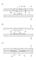
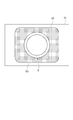
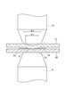
- (A) to (C) are process explanatory views schematically showing the state of the processing process and the arrangement process. It is a top view seen from the I direction in FIG. 3 (A). It is a process explanatory drawing which shows the state of the arrangement process schematically. It is a process explanatory drawing which shows the state of a pressurizing process schematically. It is a process explanatory drawing which shows the state of a pressurizing process schematically. It is a process explanatory drawing which shows the state of a pressurizing process schematically. It is a process explanatory drawing which shows the state of a pressurizing process schematically. FIG.
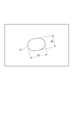
- FIG. 8 is a cross-sectional view taken along the line IX-IX in FIG. It is a process explanatory drawing which shows the state of the energization process schematically. It is a process explanatory drawing which shows the state of the energization process schematically. It is a schematic plan view of a nugget explaining the roundness of a nugget. It is sectional drawing of the aluminum welded joint explaining the penetration rate of molten aluminum into an aluminum plate in a nugget. It is the schematic side view which shows typically the example which uses the flat type electrode.
- FIG. 1 is a schematic configuration diagram showing a main part of a spot welder for welding an aluminum material.
- the spot welder 11 includes a pair of electrodes 13 and 15, a welding transformer unit 17 connected to the pair of electrodes 13 and 15, and a control unit 19 that supplies welding power from the power supply unit 18 to the welding transformer unit 17. It includes an electrode driving unit 20 that moves the pair of electrodes 13 and 15 in the axial direction.
- the control unit 19 integrally controls the current value, energization time, electrode pressurization, energization timing, pressurization timing, and the like.
- the spot welder 11 superimposes and sandwiches at least two plate materials of the first aluminum plate 21 and the second aluminum plate 23, which are aluminum materials, between the pair of electrodes 13 and 15. Then, the first aluminum plate 21 and the second aluminum plate 23 are pressed in the plate thickness direction by driving the electrodes 13 and 15 by the electrode driving unit 20. In this pressurized state, electricity is applied between the electrodes 13 and 15. As a result, a nugget N is formed between the first aluminum plate 21 and the second aluminum plate 23 sandwiched between the electrodes 13 and 15, and the first aluminum plate 21 and the second aluminum plate 23 are integrated by aluminum welding. A joint (joint) 27 is obtained.
- a welded joint 27 made of an aluminum material but the present invention is not limited to the case where two aluminum plates are joined, but the case where three or more aluminum plates are joined. It is also suitably used for.
- the pair of electrodes 13 and 15 are R-shaped or DR-shaped electrodes having a curved end face. Further, each of the pair of electrodes 13 and 15 is provided with a cooling unit inside.
- the cooling method of the cooling unit is not particularly limited, but in the configuration of the illustrated example, the cooling pipe 33 is arranged in the recesses 31 formed in each of the electrodes 13 and 15, and a cooling medium such as water is supplied from the cooling pipe 33. By doing so, the electrodes 13 and 15 are cooled.
- the first aluminum plate 21 and the second aluminum plate 23 are heat-treated aluminum alloys, specifically, 6000-based aluminum alloys.
- the thickness of the first aluminum plate 21 and the second aluminum plate 23 (including the aluminum plate when another aluminum plate is used) is 0.5 mm or more in the use of structural members such as automobile skeleton members. It is preferably 2.0 mm or more, more preferably 2.0 mm or more.
- the thickness of each aluminum plate may be equal, and one of them may be thicker than the other.
- the form of the aluminum material is not limited to the above-mentioned aluminum plate (rolled plate), and may be an extruded material, a forged material, or a cast material.
- FIG. 2 is a timing chart showing an example of the waveforms of the welding current and the pressing force.
- the control unit 19 energizes the welding current Iw between the electrodes 13 and 15 during the pressurization time tp from the start of pressurization by the electrodes 13 and 15 to the end of pressurization.
- the welding current Iw energized between the electrodes 13 and 15 is a single pulse current.
- the welding current Iw is energized after a time ta from the start of pressurization by the electrodes 13 and 15, and the energization is maintained for the time ti. Then, the pressurization by the electrodes 13 and 15 is stopped after a time tb after the completion of energization of the welding current Iw.
- the welding current Iw is 15 to 30 kA, and the energization time ti of the welding current Iw is 100 to 500 ms.
- the pressing force by the electrodes 13 and 15 is 2 to 4 kN.
- the time ta from the start of pressurization to the start of energization is 600 ms, and the time tb from the end of energization to the end of pressurization is 400 ms.
- the first aluminum plate 21 is embossed. Specifically, a plan-view circular emboss E that bulges in the stacking direction toward the second aluminum plate 23 is formed at the planned welding position on the first aluminum plate 21 by press working or the like. When the emboss E is formed in this way, in the first aluminum plate 21, the peripheral portion Es of the emboss E becomes harder than the other portions due to work hardening.
- the outer diameter ⁇ of the emboss E is 3 ⁇ t to 7 ⁇ tmm (t is the plate thickness), and the emboss height from the surface of the first aluminum plate 21 on the second aluminum plate 23 side to the top Et of the emboss E. h is preferably t / 2 mm or less, and the radius of curvature r on the protruding side of the emboss E is preferably smaller than the radius of curvature at the tips of the electrodes 13 and 15. Further, the emboss E is formed so that the diameter ⁇ n of the root portion En of the bulging portion is smaller than the tip diameter ⁇ d of the electrodes 13 and 15. In other words, as the electrodes 13 and 15 used for welding, electrodes having a tip diameter ⁇ d larger than the diameter ⁇ n of the root portion En of the emboss E are used (see FIG. 5).
- the adhesive 35 is applied to the planned welding position on the surface of the second aluminum plate 23 facing the first aluminum plate 21.
- the adhesive 35 for example, an epoxy resin is preferably used.
- the adhesive 35 may be applied to the planned welding position on the surface of the first aluminum plate 21 facing the second aluminum plate 23, and the adhesive 35 may be applied to the surface of the first aluminum plate 21 and the second aluminum plate 23 facing each other. It may be applied to the planned welding position.
- the protruding side of the emboss E of the first aluminum plate 21 is directed toward the second aluminum plate 23, and the first aluminum plate 21 and the second aluminum plate 23 are overlapped with each other.
- the first aluminum plate 21 and the second aluminum plate 23 which are overlapped with each other are arranged between the pair of electrodes 13 and 15, and the first aluminum plate 21 and the second aluminum plate 23 are arranged.
- the planned welding position is arranged at the pressurized energization position by the electrodes 13 and 15.
- the electrode driving unit 20 sandwiches the first aluminum plate 21 and the second aluminum plate 23 between the electrodes 13 and 15 and pressurizes them in the plate thickness direction.
- the pressing force by the electrodes 13 and 15 is preferably 2 to 4 kN.
- the embossed E is formed on the central side including the top Et with the peripheral edge Es hardened by work hardening as a fulcrum. It deforms in the direction opposite to the protruding direction.
- the embossed E is in a state in which the central side is recessed and only the peripheral edge portion Es is slightly annularly projected toward the second aluminum plate 23 side, and the embossed E projecting in the annular shape.
- the peripheral portion Es of the above is in contact with the second aluminum plate 23.
- the Vickers hardness of the peripheral portion Es of the embossed E is Hs
- the Vickers hardness of the top Et of the embossed E is Ht
- the Vickers hardness of the base material which is the hardness of the first aluminum plate 21 itself.
- the rigidity of the top Et of the embossing E is lower than that of the peripheral portion Es. Therefore, as described above, the central side is recessed and only the peripheral portion Es moves to the second aluminum plate 23 side. It is in a slightly annularly projected state, and a slight gap G is formed on the center side of the emboss E. Moreover, when the difference
- electrodes 13 and 15 used for welding electrodes having a tip diameter ⁇ d larger than the diameter ⁇ n of the root portion En of the bulging portion of the embossed E are used.
- the electrode 13 is evenly applied to the root portion En of the embossed E to pressurize the embossed E, and the embossed E can be uniformly crushed.
- the welding current Iw is applied between the welding transformer portion 17 and the electrodes 13 and 15. Then, as shown in FIG. 10, the first aluminum plate 21 and the second aluminum plate 23 start melting at the planned welding positions between the electrodes 13 and 15. At this time, since the peripheral portion Es of the embossed E is pressed against the surface of the second aluminum plate 23 and the gap G is formed on the central side of the embossed E, the melting at the planned welding position is from the peripheral portion Es of the embossed E. It starts and progresses toward the center. As a result, the gap G is filled with the molten aluminum without the molten aluminum generated by energization flowing out to the outer peripheral side of the emboss E.
- nuggets N are formed at the planned welding positions of the first aluminum plate 21 and the second aluminum plate 23, and the first aluminum plate 21 and the second aluminum plate 21 are energized.
- An aluminum welded joint 27 integrated with the 23 is formed.
- the electrodes 13 and 15 are separated from each other, and the aluminum welded joint 27 in which the first aluminum plate 21 and the second aluminum plate 23 are integrated is taken out from the spot welder 11.
- a circular emboss E is formed in advance.
- the peripheral portion Es of the embossed E formed in this manner is work-hardened.
- the planned welding positions are overlapped with the bulging side of the emboss E toward the aluminum plate 23, and the first aluminum plate 21 and the second aluminum plate 23 which are overlapped with each other are sandwiched between the electrodes 13 and 15 to pressurize.
- the central side of the embossed E is recessed, leaving the work-hardened peripheral portion Es of the embossed E, and energization is performed between the electrodes 13 and 15 while continuing the pressurization. Then, the first aluminum plate 21 and the second aluminum plate 23 start melting at the planned welding positions between the electrodes 13 and 15.
- the Vickers hardness Hs of the peripheral portion Es of the embossed E, the Vickers hardness Ht of the top Et of the embossed E, and the Vickers hardness Hb of the aluminum material 21 itself as the base material satisfy the relationship of Hs> Ht ⁇ Hb.
- the rigidity of the peripheral portion Es of the embossed E and the top Et of the embossed E is improved, so that the embossed E is less likely to be crushed, the adhesive 35 is satisfactorily removed to the outer peripheral side during pressurization, and the influence of the adhesive 35 during welding. Can be suppressed.
- the peripheral portion Es of the embossed E and the top Et of the embossed E can be better eliminated during pressurization.
- the roundness of the nugget N is the absolute value
- the penetration rate of the nugget N is represented by the ratio ⁇ / ⁇ of the thickness ⁇ of the welded portion and the thickness ⁇ of the nugget N in cross-sectional view, and is preferably 0.3 to 0.7. Is.
- R-shaped or DR-shaped electrodes having curved end faces are used as the electrodes 13 and 15. Since the tip surfaces of the electrodes 13 and 15 are curved surfaces, the influence of the angle variation of the electrodes 13 and 15 and the one-sided contact (non-uniform contact) of the electrodes is suppressed as compared with the flat tip-shaped electrode, and the aluminum plate 21 , 23 can be stably pressurized. As a result, a nugget N with high roundness can be formed and welded with high quality.
- the adhesive 35 is applied to the planned welding position on the surface of the second aluminum plate 23 facing the first aluminum plate 21 before the placement process.
- the aluminum plates 21 and 23 can be bonded to each other with the adhesive 35 around the welded portion on which the nugget N is formed, and the joining of the joined portion by spot welding and the adhesion by the adhesive 35 are combined to make it stronger.
- the adhesive 35 is pushed out to the outer peripheral side of the planned welding position when the stacked aluminum plates 21 and 23 are pressed by the electrodes 13 and 15. be able to. Therefore, the influence of the adhesive 35 at the welded portion between the aluminum plates 21 and 23 can be suppressed, and spot welding is performed satisfactorily.
- a high-strength aluminum welded joint 27 joined by the adhesive 35 can be obtained.
- the R-shaped or DR-shaped electrodes 13 and 15 having curved end faces are used, but as shown in FIG. 14, the electrode tip surfaces of the electrodes 13 and 15 are flat and the electrode has a flat surface.
- An F-shaped electrode having a tip diameter ⁇ d larger than the diameter ⁇ n at the base of the embossed bulge may be used. If F-shaped electrodes having flat end faces are used as the electrodes 13 and 15, since the tip faces of the electrodes 13 and 15 are flat, the entire planned welding position where the emboss E is formed can be pressurized in a well-balanced manner. As a result, a nugget N with high roundness can be formed and welded with high quality.
- the adhesive 35 is applied to the surface of the aluminum plate 23 facing the aluminum plate 21, but the present invention is also applicable to the case of welding without using the adhesive 35.
- Table 1 shows the measurement results when embossing of different heights was formed on one aluminum plate and welded without applying an adhesive.
- the ⁇ of the evaluation result represents the case where all the
- Test Example 1 welded without applying an adhesive, the nugget had an appropriate penetration rate and a high roundness was obtained in all of Test Examples 1-1 to 1-4 having different embossing heights. , Good evaluation ( ⁇ ) was obtained.
- Test Example 2 The measurement results when embossing of different heights is formed on one aluminum plate, an adhesive is applied and welded are shown in Test Examples 2-1 to 2-4 of Table 2. Further, as a comparative example, Test Example 2-5 shows the measurement results when the flat plate is coated with the adhesive and welded.
- Table 2 in Test Examples 2-1 to 2-4, the Vickers hardness Hs at the peripheral edge of the emboss, the Vickers hardness Ht at the top of the emboss, the measured values of the Vickers hardness Hb of the aluminum material as the base material, and the Vickers hardness Hb of the embossing.
- Hs-Ht The difference
- Table 2 shows the measured values of the Vickers hardness Hb of the aluminum material as the base material in Test Example 2-5.
- the nugget had an appropriate penetration rate in all of Test Examples 2-1 to 2-4 having different embossing heights. Further, in Test Example 2-1 and Test Example 2-2, the nugget was formed with a high roundness, and dust and cracks did not occur at the welded portion, so that the evaluation was good ( ⁇ ), and Test Example 2 -2 had the largest breaking diameter. Further, in Test Example 2-3 and Test Example 2-4, the roundness of the nugget was slightly lowered, and although it was within the permissible range, some dust was generated, so the evaluation was ( ⁇ ).
- Test Examples 2-1 to 2-4 the Vickers hardness Hs at the peripheral edge of the emboss, the Vickers hardness Ht at the top of the emboss, and the Vickers hardness Hb of the base material satisfy the relationship of Hs> Ht ⁇ Hb. There is. In this case, it is considered that the rigidity of the peripheral portion of the emboss and the top of the emboss is improved, so that the emboss is less likely to be crushed, and the adhesive is satisfactorily removed to the outer peripheral side during pressurization to suppress dust.
- Test Example 2-5 which is a flat plate, had the worst roundness of the nugget, and was evaluated as (x) because dust and cracks occurred at the welded portion.
- the present invention is not limited to the above-described embodiment, and can be modified or applied by those skilled in the art based on the combination of the configurations of the embodiments with each other, the description of the specification, and well-known techniques. It is the planned invention and is included in the scope of seeking protection.
- a spot welding method for aluminum materials in which a plurality of aluminum materials are stacked and spot welded.
- a pressurizing step in which the aluminum materials overlapped with each other are sandwiched between the electrodes and pressed to push the center side while leaving the peripheral portion of the embossing.
- a plan-view circular embossing is formed in advance at a position to be welded on at least one aluminum material so as to bulge in the stacking direction toward the other aluminum material. The embossing formed in this way is uniformly crushed by the electrodes, and the peripheral portion thereof is work-hardened.
- the bulging side of the embossing is directed toward another aluminum material, and the planned welding positions of the aluminum materials are overlapped with each other, and the aluminum materials overlapped with each other are sandwiched between electrodes to pressurize. Then, the center side is pushed in and dented while leaving the work-hardened peripheral portion of the emboss, and energization is performed between the electrodes while continuing the pressurization. Then, the aluminum material starts melting at the planned welding position between the electrodes.
- the gap can be filled with the molten aluminum to form a nugget without causing the molten aluminum generated by energization to flow out to the outer peripheral side of the embossing.
- a high-quality bonded body in which the aluminum materials are well bonded to each other by forming a nugget having a high roundness and an excellent penetration rate into the aluminum material which is the base material can be obtained.
- molten aluminum does not adhere to the surface of the electrode, and it is not necessary to frequently dress the electrode, which improves production efficiency.
- the rigidity of the peripheral portion of the emboss and the top of the emboss is improved, so that the emboss is less likely to be crushed, the adhesive is satisfactorily removed to the outer peripheral side during pressurization, and the influence of the adhesive during welding can be suppressed.
- An aluminum material in which the spot welded portion is embossed, and the Vickers hardness Hs at the peripheral edge of the emboss, the Vickers hardness Ht at the top of the emboss, and the Vickers hardness Hb of the base material are Hs> Ht ⁇ .
- Electrode 21 First aluminum plate (aluminum material) 23 Second aluminum plate (aluminum material) 35 Adhesive E Embossed En Root part Es Peripheral part ⁇ d Tip diameter ⁇ n Root diameter
Landscapes
- Engineering & Computer Science (AREA)
- Mechanical Engineering (AREA)
- General Engineering & Computer Science (AREA)
- Resistance Welding (AREA)
Abstract
Description
(1) 複数のアルミニウム材を重ねてスポット溶接するアルミニウム材のスポット溶接方法であって、
少なくとも一枚の前記アルミニウム材における溶接予定位置に、他の前記アルミニウム材側への重ね合わせ方向へ膨出する平面視円形状のエンボスを形成する加工工程と、
前記エンボスの膨出側を他の前記アルミニウム材へ向けて前記アルミニウム材の溶接予定位置同士を重ね合わせ、前記溶接予定位置を一対の電極間に配置させる配置工程と、
互いに重ね合わせた前記アルミニウム材を前記電極で挟み込んで加圧することで、前記エンボスの周縁部を残して中心側を押し込む加圧工程と、
前記電極による加圧を継続させながら前記電極間に通電を行う通電工程と、
を含み、
前記電極として、前記エンボスの膨出部根元側の径よりも大きい先端径を有する電極を用いるアルミニウム材のスポット溶接方法。
(2) スポット溶接部にエンボス成形が施されたアルミニウム材であって、前記エンボスの周縁部のビッカース硬度Hs、エンボスの頂部のビッカース硬度Htおよび母材のビッカース硬度Hbが、Hs>Ht≧Hbの関係を満たすアルミニウム材。
<スポット溶接機>
図1はアルミニウム材を溶接するスポット溶接機の要部を示す概略構成図である。
第1アルミニウム板21及び第2アルミニウム板23は、熱処理系のアルミニウム合金、具体的には、6000系のアルミニウム合金である。第1アルミニウム板21と第2アルミニウム板23(さらに他のアルミニウム板を用いる場合はそのアルミニウム板を含む)の板厚は、例えば自動車の骨格部材等の構造部材の用途では、0.5mm以上が好ましく、2.0mm以上がより好ましい。各アルミニウム板の板厚は等しくてもよく、いずれか一方が他方より厚くてもよい。また、アルミニウム材の形態は、上記したアルミニウム板(圧延板)に限らず、押出材や鍛造材、鋳造材であってもよい。
図2は溶接電流と加圧力の波形の一例を示すタイミングチャートである。
図2に示すように、制御部19によって、電極13,15による加圧開始から加圧終了までの加圧時間tpの間に電極13,15の間に溶接電流Iwを通電する。この電極13,15の間に通電する溶接電流Iwは、単一のパルス電流とする。溶接電流Iwは、電極13,15による加圧開始から時間ta後に通電が開始され、時間tiの間、通電が維持される。そして、電極13,15による加圧は、溶接電流Iwの通電終了後、時間tb後に停止する。
(加工工程)
図3の(A)及び図4に示すように、第1アルミニウム板21に対してエンボス加工を施す。具体的には、プレス加工等により、第1アルミニウム板21における溶接予定位置に、第2アルミニウム板23側への重ね合わせ方向へ膨出する平面視円形状のエンボスEを形成する。このように、エンボスEを形成すると、第1アルミニウム板21では、エンボスEの周縁部Esが加工硬化によって他の部分よりも硬くなる。
図3の(B)に示すように、第2アルミニウム板23の第1アルミニウム板21との対向面における溶接予定位置に、接着剤35を塗布する。この接着剤35としては、例えばエポキシ樹脂が好適に用いられる。なお、接着剤35は、第1アルミニウム板21の第2アルミニウム板23との対向面における溶接予定位置に塗布してもよく、第1アルミニウム板21及び第2アルミニウム板23の互いの対向面における溶接予定位置に塗布してもよい。
図3(C)に示すように、第1アルミニウム板21のエンボスEの突出側を第2アルミニウム板23に向け、第1アルミニウム板21と第2アルミニウム板23とを互いに重ね合わせる。次に、図5に示すように、互いに重ね合わせた第1アルミニウム板21と第2アルミニウム板23を一対の電極13,15の間に配置させ、第1アルミニウム板21及び第2アルミニウム板23の溶接予定位置を電極13,15による加圧通電位置に配置させる。
次に、電極駆動部20によって、第1アルミニウム板21と第2アルミニウム板23とを電極13,15で挟み込んで板厚方向に加圧する。この場合の電極13,15による加圧力は、2~4kNとするのが好ましい。
この状態で加圧状態を維持しながら、溶接トランス部17から電極13,15間に溶接電流Iwを通電する。すると、図10に示すように、第1アルミニウム板21及び第2アルミニウム板23は、その電極13,15間の溶接予定位置において溶融が始まる。このとき、第2アルミニウム板23の表面にエンボスEの周縁部Esが押し付けられ、エンボスEの中心側に隙間Gが形成されているので、溶接予定位置における溶融は、エンボスEの周縁部Esから開始されて中心へ向かって進行する。これにより、通電によって生じた溶融アルミニウムがエンボスEの外周側へ流れ出ることなく、隙間Gが溶融アルミニウムで満たされる。
(アルミニウム材)
材質:A6022
板厚t:1.0mm
(電極)
種別:クロム銅(CrCu)R形電極
先端曲率半径:100mm
電極直径(元径):19mm
電極間加圧力:2.7kN
溶接電流:22kA
(試験例1)
一枚のアルミニウム板に高さの異なるエンボスを形成し、接着剤を塗布せずに溶接した場合の測定結果を表1に示す。評価結果の○は、ナゲットの|d1-d2|値が全て1未満の場合、△は|d1-d2|値が1以上のものが1個の場合を表す。
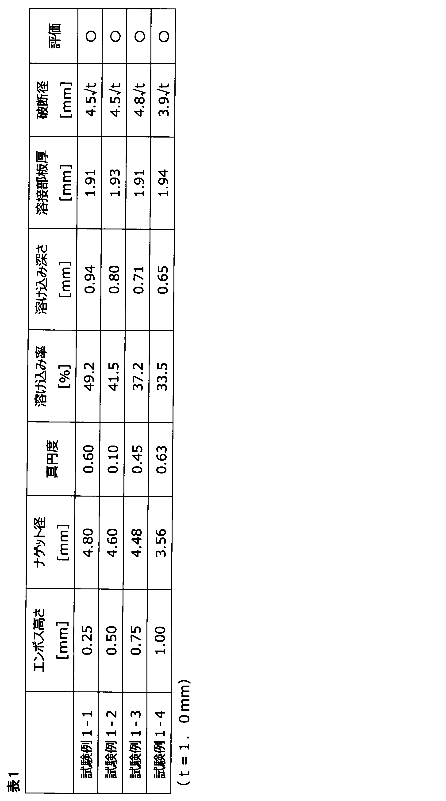
一枚のアルミニウム板に高さの異なるエンボスを形成し、接着剤を塗布して溶接した場合の測定結果を表2の試験例2-1~2-4に示す。また、比較例として平板に接着剤を塗布して溶接した場合の測定結果を試験例2-5に示す。表2には、試験例2-1~2-4において、エンボスの周縁部のビッカース硬度Hs、エンボスの頂部のビッカース硬度Ht、母材であるアルミニウム材のビッカース硬度Hbの測定値、及びエンボスの周縁部のビッカース硬度Hsとエンボスの頂部のビッカース硬度Htとの差|Hs-Ht|を表記した。また、表2には、試験例2-5において、母材であるアルミニウム材のビッカース硬度Hbの測定値を表記した。なお、各硬度Hs,Ht,Hbの測定荷重は100kgとし、それぞれ図3の(A)に示す測定位置Ps,Pt,Pbで測定した。

(1) 複数のアルミニウム材を重ねてスポット溶接するアルミニウム材のスポット溶接方法であって、
少なくとも一枚の前記アルミニウム材における溶接予定位置に、他の前記アルミニウム材側への重ね合わせ方向へ膨出する平面視円形状のエンボスを形成する加工工程と、
前記エンボスの膨出側を他の前記アルミニウム材へ向けて前記アルミニウム材の溶接予定位置同士を重ね合わせ、前記溶接予定位置を一対の電極間に配置させる配置工程と、
互いに重ね合わせた前記アルミニウム材を前記電極で挟み込んで加圧することで、前記エンボスの周縁部を残して中心側を押し込む加圧工程と、
前記電極による加圧を継続させながら前記電極間に通電を行う通電工程と、
を含み、
前記電極として、前記エンボスの膨出部根元側の径よりも大きい先端径を有する電極を用いるアルミニウム材のスポット溶接方法。
このアルミニウム材のスポット溶接方法によれば、少なくとも一枚のアルミニウム材における溶接予定位置に、他のアルミニウム材側への重ね合わせ方向へ膨出する平面視円形状のエンボスを予め形成する。このようにして形成したエンボスは、電極によって均一に押し潰され、その周縁部が加工硬化する。このエンボスの膨出側を他のアルミニウム材へ向けてアルミニウム材の溶接予定位置同士を重ね合わせ、互いに重ね合わせたアルミニウム材を電極で挟み込んで加圧する。そして、エンボスの加工硬化させた周縁部を残して中心側を押し込んで凹ませ、加圧を継続させながら電極間に通電を行う。すると、アルミニウム材は、電極間の溶接予定位置において溶融が始まる。このとき、他のアルミニウム材の表面にエンボスの周縁部が押し付けられ、エンボスの中心側に隙間が形成されているので、溶接予定位置における溶融を、エンボスの周縁部から開始させてエンボスの中心へ向かって進行させることができる。また、通電によって生じた溶融アルミニウムをエンボスの外周側へ流出させることなく、隙間を溶融アルミニウムで満たしてナゲットを形成できる。これにより、真円度が高く、しかも、母材であるアルミニウム材への溶け込み率に優れたナゲットを形成してアルミニウム材同士が良好に接合された高品質な接合体が得られる。また、ナゲットが厚くなりすぎて表面に露出するのを抑制できるので、電極の表面に溶融アルミニウムが付着せず、電極のドレッシングを頻繁に実施する必要がなくなり、生産効率が向上する。
前記エンボスの周縁部のビッカース硬度Hs、前記エンボスの頂部のビッカース硬度Htおよび前記アルミニウム材のビッカース硬度HbがHs>Ht≧Hbの関係を満たす前記エンボスを設ける請求項1に記載のアルミニウム材のスポット溶接方法。
このアルミニウム材のスポット溶接方法によれば、エンボスの周縁部のビッカース硬度Hs、エンボスの頂部のビッカース硬度Htおよび母材のビッカース硬度Hbが、Hs>Ht≧Hbの関係を満たしている。これにより、エンボスの周縁部とエンボスの頂部の剛性向上により、エンボスが潰れにくくなり、加圧時に接着剤を外周側へ良好に排除させ、溶接時における接着剤の影響を抑えられる。
このアルミニウム材のスポット溶接方法によれば、エンボスの周縁部とエンボスの頂部の剛性をバランスよく向上させることにより、加圧時に接着剤をより良好に排除できる。
このアルミニウム材のスポット溶接方法によれば、電極の先端面が曲面であるので、電極の角度のバラツキによる影響を抑え、アルミニウム材に対して安定した加圧ができる。これにより、真円度の高いナゲットを形成して高品質に溶接できる。
このアルミニウム材のスポット溶接方法によれば、電極の先端面が平面であるので、エンボスを形成した溶接予定位置の全体をバランスよく加圧できる。これにより、真円度の高いナゲットを形成して高品質に溶接できる。
このアルミニウム材のスポット溶接方法によれば、ナゲットを形成した溶接箇所の周囲において、アルミニウム材同士を接着剤で接着できる。また、スポット溶接による接合箇所を接着剤により強固に接合でき、特に耐剥離性を高めて接合体の面剛性を向上させることができる。しかも、アルミニウム材にエンボスを形成していることで、重ね合わせたアルミニウム材を電極で加圧した際に、接着剤が溶接予定位置の外周側へ押し出される。したがって、アルミニウム材同士の溶接個所における接着剤による影響を抑制でき、良好にスポット溶接を実施できる。これにより、接着剤で接着された高強度な接合体が得られる。
このアルミニウム材によれば、エンボスの周縁部のビッカース硬度Hs、エンボスの頂部のビッカース硬度Htおよび母材のビッカース硬度Hbが、Hs>Ht≧Hbの関係を満たしている。これにより、このアルミニウム材と平板からなるアルミニウム材とを加圧してスポット溶接する際に、エンボスの周縁部とエンボスの頂部の剛性向上により、エンボスが潰れにくくなり、加圧時に接着剤を外周側へ良好に排除させ、溶接時における接着剤の影響を抑えることができる。
このアルミニウム材によれば、エンボスの周縁部とエンボスの頂部の剛性がバランスよく向上されているので、このアルミニウム材と平板からなるアルミニウム材とを加圧してスポット溶接する際に、加圧時に接着剤をより良好に排除できる。
21 第1アルミニウム板(アルミニウム材)
23 第2アルミニウム板(アルミニウム材)
35 接着剤
E エンボス
En 根元部
Es 周縁部
φd 先端径
φn 根元部の径
Claims (12)
- 複数のアルミニウム材を重ねてスポット溶接するアルミニウム材のスポット溶接方法であって、
少なくとも一枚の前記アルミニウム材における溶接予定位置に、他の前記アルミニウム材側への重ね合わせ方向へ膨出する平面視円形状のエンボスを形成する加工工程と、
前記エンボスの膨出側を他の前記アルミニウム材へ向けて前記アルミニウム材の溶接予定位置同士を重ね合わせ、前記溶接予定位置を一対の電極間に配置させる配置工程と、
互いに重ね合わせた前記アルミニウム材を前記電極で挟み込んで加圧することで、前記エンボスの周縁部を残して中心側を押し込む加圧工程と、
前記電極による加圧を継続させながら前記電極間に通電を行う通電工程と、
を含み、
前記電極として、前記エンボスの膨出部根元側の径よりも大きい先端径を有する電極を用いる
ことを特徴とするアルミニウム材のスポット溶接方法。 - 前記エンボスを形成する加工工程において、
前記エンボスの周縁部のビッカース硬度Hs、前記エンボスの頂部のビッカース硬度Htおよび前記アルミニウム材のビッカース硬度HbがHs>Ht≧Hbの関係を満たす前記エンボスを設ける請求項1に記載のアルミニウム材のスポット溶接方法。 - 前記エンボスの周縁部のビッカース硬度Hsと前記エンボスの頂部のビッカース硬度Htとの差|Hs-Ht|が10以内である請求項1に記載のアルミニウム材のスポット溶接方法。
- 前記エンボスの周縁部のビッカース硬度Hsと前記エンボスの頂部のビッカース硬度Htとの差|Hs-Ht|が10以内である請求項2に記載のアルミニウム材のスポット溶接方法。
- 前記電極として曲面からなる端面を有するR形又はDR形の電極を用いる請求項1~4のいずれか一項に記載のアルミニウム材のスポット溶接方法。
- 前記電極として、平面からなる端面を有するF形の電極を用いる請求項1~4いずれか一項に記載のアルミニウム材のスポット溶接方法。
- 前記配置工程前に、前記アルミニウム材の対向面における前記溶接予定位置の少なくとも一方に接着剤を塗布する接着剤塗布工程を行う請求項1~4のいずれか一項に記載のアルミニウム材のスポット溶接方法。
- 前記配置工程前に、前記アルミニウム材の対向面における前記溶接予定位置の少なくとも一方に接着剤を塗布する接着剤塗布工程を行う請求項5に記載のアルミニウム材のスポット溶接方法。
- 前記配置工程前に、前記アルミニウム材の対向面における前記溶接予定位置の少なくとも一方に接着剤を塗布する接着剤塗布工程を行う請求項6に記載のアルミニウム材のスポット溶接方法。
- 前記配置工程前に、前記アルミニウム材の対向面における前記溶接予定位置の少なくとも一方に接着剤を塗布する接着剤塗布工程を行う請求項7に記載のアルミニウム材のスポット溶接方法。
- スポット溶接部にエンボス成形が施されたアルミニウム材であって、前記エンボスの周縁部のビッカース硬度Hs、前記エンボスの頂部のビッカース硬度Htおよび母材のビッカース硬度Hbが、Hs>Ht≧Hbの関係を満たすアルミニウム材。
- 前記エンボスの周縁部のビッカース硬度Hsと前記エンボスの頂部のビッカース硬度Htとの差|Hs-Ht|が10以内である請求項11に記載のアルミニウム材。
Priority Applications (3)
| Application Number | Priority Date | Filing Date | Title |
|---|---|---|---|
| CN202080024620.2A CN113613822B (zh) | 2019-03-29 | 2020-03-19 | 铝材的点焊方法和铝材 |
| KR1020217030279A KR102584822B1 (ko) | 2019-03-29 | 2020-03-19 | 알루미늄재의 스폿 용접 방법 및 알루미늄재 |
| US17/435,754 US12233472B2 (en) | 2019-03-29 | 2020-03-19 | Spot welding method for aluminum material and aluminum material |
Applications Claiming Priority (4)
| Application Number | Priority Date | Filing Date | Title |
|---|---|---|---|
| JP2019-068388 | 2019-03-29 | ||
| JP2019068388 | 2019-03-29 | ||
| JP2020026162A JP6762445B1 (ja) | 2019-03-29 | 2020-02-19 | アルミニウム材のスポット溶接方法 |
| JP2020-026162 | 2020-02-19 |
Publications (1)
| Publication Number | Publication Date |
|---|---|
| WO2020203375A1 true WO2020203375A1 (ja) | 2020-10-08 |
Family
ID=72614677
Family Applications (1)
| Application Number | Title | Priority Date | Filing Date |
|---|---|---|---|
| PCT/JP2020/012522 Ceased WO2020203375A1 (ja) | 2019-03-29 | 2020-03-19 | アルミニウム材のスポット溶接方法及びアルミニウム材 |
Country Status (5)
| Country | Link |
|---|---|
| US (1) | US12233472B2 (ja) |
| JP (1) | JP6762445B1 (ja) |
| KR (1) | KR102584822B1 (ja) |
| CN (1) | CN113613822B (ja) |
| WO (1) | WO2020203375A1 (ja) |
Cited By (1)
| Publication number | Priority date | Publication date | Assignee | Title |
|---|---|---|---|---|
| JP7609219B1 (ja) | 2023-09-14 | 2025-01-07 | フジテック株式会社 | エスカレータ |
Families Citing this family (6)
| Publication number | Priority date | Publication date | Assignee | Title |
|---|---|---|---|---|
| CN115335176A (zh) * | 2020-03-27 | 2022-11-11 | 富山县 | 金属材料的接合方法 |
| JP7564013B2 (ja) * | 2021-02-19 | 2024-10-08 | 株式会社神戸製鋼所 | アルミニウム材のスポット溶接方法及びアルミニウム材の接合方法 |
| JP7858329B2 (ja) * | 2022-02-10 | 2026-05-14 | 株式会社Subaru | スポット溶接方法及びスポット溶接装置 |
| KR102773336B1 (ko) * | 2022-07-06 | 2025-02-27 | 가부시키가이샤 고베 세이코쇼 | 알루미늄 또는 알루미늄 합금재의 스폿 용접 방법 및 용접 조인트 |
| CN116532771B (zh) * | 2023-05-31 | 2026-05-12 | 东风汽车有限公司东风日产乘用车公司 | 一种铝合金型材的焊接方法 |
| CN117139838A (zh) * | 2023-08-19 | 2023-12-01 | 上海交通大学 | 铝/钢异种金属基于胶接微凸结构辅助激光飞行焊方法 |
Citations (2)
| Publication number | Priority date | Publication date | Assignee | Title |
|---|---|---|---|---|
| JPH05285669A (ja) * | 1992-04-10 | 1993-11-02 | Sunstar Eng Inc | 板材の接合方法 |
| JP2017225990A (ja) * | 2016-06-21 | 2017-12-28 | 三菱電機株式会社 | スポット溶接方法、貯湯タンクの製造方法、貯湯タンク及びバッフル |
Family Cites Families (14)
| Publication number | Priority date | Publication date | Assignee | Title |
|---|---|---|---|---|
| CA1051050A (en) * | 1976-01-02 | 1979-03-20 | Joseph J. Trytek | Rotary end face seal |
| DE3100677A1 (de) | 1980-02-11 | 1981-11-26 | Opprecht, Paul, 8962 Bergdietikon, Aargau | Buckel zum elektrischen widerstandsschweissen von aluminiumblechen und verfahren zu seiner herstellung |
| EP0088231B1 (de) | 1982-03-04 | 1988-07-20 | Elpatronic Ag | Elektrisches Widerstandspressschweissverfahren zum Verschweissen von aus Aluminiumwerkstoffen bestehenden Werkstückteilen und Einrichtung sowie Elektrode hierfür |
| JPH05383A (ja) | 1991-06-13 | 1993-01-08 | Kawasaki Steel Corp | アルミニウム合金板のスポツト溶接方法 |
| JPH06170549A (ja) | 1992-11-16 | 1994-06-21 | Nasu Tooa Kk | アルミニウムのプロジェクション溶接方法及びアルミニウムのプロジェクション溶接機 |
| US5783794A (en) * | 1993-11-15 | 1998-07-21 | Nippon Steel Corporation | Method and material for resistance welding steel-base metal sheet to aluminum-base metal sheet |
| JP3862640B2 (ja) | 2002-09-06 | 2006-12-27 | 株式会社神戸製鋼所 | アルミニウム系材の抵抗スポット溶接方法 |
| JP2006196428A (ja) * | 2004-05-31 | 2006-07-27 | Nissan Motor Co Ltd | 組電池およびその製造方法 |
| US9180548B2 (en) * | 2008-06-06 | 2015-11-10 | GM Global Technology Operations LLC | Method for one-sided, one step joining of a metal sheet stack |
| JP6060579B2 (ja) | 2012-09-18 | 2017-01-18 | Jfeスチール株式会社 | 抵抗スポット溶接方法 |
| JP6186208B2 (ja) | 2013-08-22 | 2017-08-23 | 日本アビオニクス株式会社 | 溶接装置 |
| NL2011446C2 (en) * | 2013-09-16 | 2015-03-18 | Al S Technology B V | Projection welding metal sheets. |
| US20150231730A1 (en) * | 2014-02-17 | 2015-08-20 | GM Global Technology Operations LLC | Resistance spot welding steel and aluminum workpieces with protuberance |
| DE102015002279B4 (de) * | 2015-02-21 | 2019-10-17 | Audi Ag | Schweißverfahren zum Verbinden von Bauteilen |
-
2020
- 2020-02-19 JP JP2020026162A patent/JP6762445B1/ja active Active
- 2020-03-19 KR KR1020217030279A patent/KR102584822B1/ko active Active
- 2020-03-19 WO PCT/JP2020/012522 patent/WO2020203375A1/ja not_active Ceased
- 2020-03-19 US US17/435,754 patent/US12233472B2/en active Active
- 2020-03-19 CN CN202080024620.2A patent/CN113613822B/zh active Active
Patent Citations (2)
| Publication number | Priority date | Publication date | Assignee | Title |
|---|---|---|---|---|
| JPH05285669A (ja) * | 1992-04-10 | 1993-11-02 | Sunstar Eng Inc | 板材の接合方法 |
| JP2017225990A (ja) * | 2016-06-21 | 2017-12-28 | 三菱電機株式会社 | スポット溶接方法、貯湯タンクの製造方法、貯湯タンク及びバッフル |
Cited By (1)
| Publication number | Priority date | Publication date | Assignee | Title |
|---|---|---|---|---|
| JP7609219B1 (ja) | 2023-09-14 | 2025-01-07 | フジテック株式会社 | エスカレータ |
Also Published As
| Publication number | Publication date |
|---|---|
| US12233472B2 (en) | 2025-02-25 |
| CN113613822B (zh) | 2023-07-28 |
| US20220152726A1 (en) | 2022-05-19 |
| CN113613822A (zh) | 2021-11-05 |
| JP2020163467A (ja) | 2020-10-08 |
| KR102584822B1 (ko) | 2023-10-04 |
| JP6762445B1 (ja) | 2020-09-30 |
| KR20210126124A (ko) | 2021-10-19 |
Similar Documents
| Publication | Publication Date | Title |
|---|---|---|
| JP6762445B1 (ja) | アルミニウム材のスポット溶接方法 | |
| JP5468350B2 (ja) | 異種金属板の接合方法 | |
| US6037559A (en) | Process for lap joining two kinds of metallic members having different melting points | |
| JP5599553B2 (ja) | 抵抗スポット溶接方法 | |
| JP5999293B1 (ja) | 抵抗スポット溶接方法および抵抗スポット溶接継手の製造方法 | |
| CN107000109A (zh) | 电阻点焊方法 | |
| CN104661784A (zh) | 接头强度优异的高强度钢板的点焊方法 | |
| JP5261984B2 (ja) | 抵抗スポット溶接方法 | |
| JP5315207B2 (ja) | 異材接合体及び異材抵抗スポット溶接方法 | |
| WO2020095847A1 (ja) | 抵抗スポット溶接方法および溶接部材の製造方法 | |
| JP2016161078A (ja) | 異材接合用リベット及び異材接合方法 | |
| CN110153544A (zh) | 电阻点焊方法 | |
| WO2015133099A1 (ja) | 抵抗スポット溶接方法 | |
| JP5609966B2 (ja) | 抵抗スポット溶接方法 | |
| JP7564013B2 (ja) | アルミニウム材のスポット溶接方法及びアルミニウム材の接合方法 | |
| WO2015133096A1 (ja) | 抵抗スポット溶接方法 | |
| JP5187806B2 (ja) | 抵抗スポット溶接方法 | |
| JP2009095881A (ja) | 溶接構造部材の製造方法 | |
| JP2021126702A (ja) | スポット溶接継手の製造方法、及びスポット溶接継手 | |
| JP5906618B2 (ja) | 抵抗スポット溶接方法 | |
| JP2022000315A (ja) | ウェルドボンド継手の製造方法 | |
| JP6060579B2 (ja) | 抵抗スポット溶接方法 | |
| JP7152439B2 (ja) | 接合部材の製造方法 | |
| WO2022071022A1 (ja) | アルミニウム材の抵抗スポット溶接方法、及びアルミニウム材の接合体 | |
| JP7853635B1 (ja) | スポット溶接継手 |
Legal Events
| Date | Code | Title | Description |
|---|---|---|---|
| 121 | Ep: the epo has been informed by wipo that ep was designated in this application |
Ref document number: 20783626 Country of ref document: EP Kind code of ref document: A1 |
|
| ENP | Entry into the national phase |
Ref document number: 20217030279 Country of ref document: KR Kind code of ref document: A |
|
| NENP | Non-entry into the national phase |
Ref country code: DE |
|
| 122 | Ep: pct application non-entry in european phase |
Ref document number: 20783626 Country of ref document: EP Kind code of ref document: A1 |
|
| WWG | Wipo information: grant in national office |
Ref document number: 17435754 Country of ref document: US |