WO2020203364A1 - 光電気混載基板 - Google Patents
光電気混載基板 Download PDFInfo
- Publication number
- WO2020203364A1 WO2020203364A1 PCT/JP2020/012402 JP2020012402W WO2020203364A1 WO 2020203364 A1 WO2020203364 A1 WO 2020203364A1 JP 2020012402 W JP2020012402 W JP 2020012402W WO 2020203364 A1 WO2020203364 A1 WO 2020203364A1
- Authority
- WO
- WIPO (PCT)
- Prior art keywords
- optical waveguide
- circuit board
- optical
- electric circuit
- electric
- Prior art date
Links
Images


Classifications
-
- G—PHYSICS
- G02—OPTICS
- G02B—OPTICAL ELEMENTS, SYSTEMS OR APPARATUS
- G02B6/00—Light guides; Structural details of arrangements comprising light guides and other optical elements, e.g. couplings
- G02B6/10—Light guides; Structural details of arrangements comprising light guides and other optical elements, e.g. couplings of the optical waveguide type
- G02B6/12—Light guides; Structural details of arrangements comprising light guides and other optical elements, e.g. couplings of the optical waveguide type of the integrated circuit kind
- G02B6/122—Basic optical elements, e.g. light-guiding paths
-
- G—PHYSICS
- G02—OPTICS
- G02B—OPTICAL ELEMENTS, SYSTEMS OR APPARATUS
- G02B6/00—Light guides; Structural details of arrangements comprising light guides and other optical elements, e.g. couplings
- G02B6/24—Coupling light guides
- G02B6/42—Coupling light guides with opto-electronic elements
Definitions
- the present invention relates to a photoelectric mixed mounting substrate.
- the electric circuit board includes an external terminal for electrically connecting to the terminal of the external board.
- an anisotropic conductive film (ACF) or an anisotropic conductive paste (ACP) is placed between the external terminal and the terminal of the external substrate, and then the external terminal and the ACF or ACP are used.
- a method (2) of thermocompression bonding with the terminal is used.
- ACF or ACP contains conductive particles, and exhibits conductivity in the thickness direction by thermocompression bonding in the thickness direction.
- the photoelectric mixed board is damaged, specifically, the optical waveguide is peeled off from the electric circuit board or the light is optical. The transmission loss of the waveguide increases. Further, there is a problem that the optical element connected to the optical / electric mixed board is damaged.
- the optical waveguide is flexible, heat and pressure during thermocompression bonding escape to the optical waveguide. Therefore, in ACF or ACP, the conductive particles are not oriented in the thickness direction, and as a result, there is a problem that the electrical connection reliability between the external terminal and the terminal of the external substrate is lowered.
- the method (2) if the heating temperature and pressure of thermocompression bonding are increased so that the conductive particles are sufficiently oriented in the thickness direction, the photoelectric mixed substrate is damaged, and further, the optical element is damaged. There is a problem.
- the present invention provides an optical / electric mixed circuit board having excellent electrical connection reliability with a printed wiring board while suppressing damage to the optical / electric mixed circuit board and the optical elements mounted therein.
- an optical waveguide and an electric circuit board are provided in order toward one side in the thickness direction, the electric circuit board includes a terminal for electrically connecting to a printed wiring board, and the terminal is the said. Includes a photoelectric mixed mounting substrate that deviates from the optical waveguide when projected in the thickness direction.
- the terminals are displaced from the optical waveguide when projected in the thickness direction. That is, the terminals do not overlap the optical waveguide.
- the terminals and the terminals of the printed wiring board can be used while suppressing the ultrasonic waves from escaping to the optical waveguide. Can be securely connected. Further, since the above-mentioned action is exhibited, ultrasonic waves having a normal output can be used, so that damage to the photoelectric mixed substrate and the optical element mounted on the substrate can be suppressed.
- the terminal and the printed wiring board are suppressed while suppressing the heat and pressure from escaping to the optical waveguide. Can be securely connected to the terminal of. Further, since the above-mentioned action is exhibited, the terminals can be thermocompression-bonded at a normal heating temperature and pressure, so that damage to the photoelectric mixed substrate and the optical element mounted therein can be suppressed.
- the terminals and the terminals of the printed wiring board can be electrically connected with excellent connection reliability while suppressing damage to the opto-electric mixed board and the optical elements mounted on the board. Can be done.
- the optical waveguide is inward in the orthogonal direction orthogonal to the thickness direction and the transmission direction with respect to the electric circuit board in a cross-sectional view along the orthogonal direction orthogonal to the thickness direction and the transmission direction.
- the photoelectric mixed mounting substrate according to (1) which is arranged.
- the optical waveguide is arranged inside the electric circuit board in cross-sectional view, so that warpage can be reduced.
- the percentage of the area of the overlapping portion of the optical waveguide and the electric circuit board with respect to the area of the electric circuit board is 5% or more and 50% or less, according to (1) or (2).
- the percentage of the area of the overlapping portion of the optical waveguide and the electric circuit board is 50% or less, so that the warp of the opto-electric mixed board can be suppressed, and thus the optical waveguide from the electric circuit board can be suppressed. Peeling can also be suppressed.
- the percentage of the area of the overlapping portion of the optical waveguide and the electric circuit board is 5% or more, the degree of freedom in the arrangement of the optical waveguide can be ensured, and the light transmission characteristics in the optical / electric mixed substrate can be ensured.
- the electric circuit board includes a metal support layer, a base insulating layer, and the terminals in this order toward one side in the thickness direction, and the metal support layer and the base with respect to the area of the metal support layer.
- the opto-electric mixed substrate according to any one of (1) to (3), wherein the percentage of the area of the overlapping portion of the insulating layer is 5% or more and 50% or less.
- the percentage of the area of the overlapping portion of the metal support layer and the base insulating layer is 50% or less, warpage due to the characteristics of the metal support layer can be suppressed, and by extension, the electric circuit board. It is also possible to suppress the peeling of the optical waveguide from the light. Since the percentage of the area of the overlapping portion of the metal support layer and the base insulating layer is 5% or more, the degree of freedom in arranging the metal support layer can be ensured.
- a plurality of the terminals are arranged at intervals in the orthogonal directions orthogonal to the thickness direction and the transmission direction, and the plurality of terminals transmit the central portion in the orthogonal direction of the optical waveguide.
- the opto-electric mixed substrate according to any one of (1) to (4), which is arranged symmetrically with respect to the center line passing along the direction.
- the terminals and the terminals of the printed wiring board are electrically connected with excellent connection reliability while suppressing damage to the opto-electric mixed board and the optical elements mounted therein. can do.
- FIG. 1 shows a plan view of an embodiment of the photoelectric mixed board of the present invention.
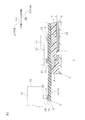
- FIG. 2 shows a side sectional view of the photoelectric mixed board shown in FIG. 1 along XX lines.
- FIG. 3 shows a normal cross-sectional view of the photoelectric mixed board shown in FIG. 1 along the YY line.
- FIG. 4 shows a plan view of an embodiment in which an optical element and a printed wiring board are mounted on the optical / electric mixed circuit board shown in FIG.
- FIG. 5 shows a modified example of the photoelectric mixed board shown in FIG. 3 (a modified example in which the entire lower surface of the base insulating layer is arranged on the upper surface of the metal support layer).
- FIG. 6 shows a modification of the optical / electric mixed board shown in FIG.
- FIG. 3 shows a modification in which optical waveguides are arranged at both ends in the width direction of the electric circuit board.
- FIG. 7 shows a further modification of the optical / electric mixed board shown in FIG. 6 (one end in the width direction of the first optical waveguide protrudes from the electric circuit board to one side in the width direction, and the other end in the width direction of the second optical waveguide is electric. A modified example) protruding from the circuit board to the other side in the width direction is shown.
- FIG. 8 shows a modified example of the optical / electric mixed substrate shown in FIG. 3 (a modified example in which an opening is formed in a region facing the first terminal in the optical waveguide).
- FIG. 9 shows a modification of the photoelectric mixed substrate shown in FIG. 3 (a modification in which a plurality of first terminals are arranged asymmetrically with respect to the center line of the optical waveguide).
- FIG. 10 shows a normal cross-sectional view of the photoelectric mixed substrate of Comparative Example 1.
- the opto-electric mixed substrate 1 has a substantially sheet shape extending in the longitudinal direction (an example of the light transmission direction).
- the photoelectric mixed board 1 includes an optical waveguide 2 and an electric circuit board 3 in order toward the upper side (an example of one side in the thickness direction).
- the optical waveguide 2 is located in the lower portion of the photoelectric mixed mounting substrate 1.
- the optical waveguide 2 has a substantially sheet shape extending in the longitudinal direction.
- the outer shape of the optical waveguide 2 is included in the outer shape of the optical / electric mixed substrate 1 in a plan view, and is specifically smaller than the electric circuit board 3 described below.
- the optical waveguide 2 is arranged at an intermediate portion (specifically, a substantially central portion) in the width direction of the photoelectric mixed mounting substrate 1.
- the center line CL passing through the central portion in the width direction of the optical waveguide 2 and along the longitudinal direction passes through the central portion in the width direction of the photoelectric mixed substrate 1 and coincides with the center line along the longitudinal direction.
- the optical waveguide 2 includes an underclad layer 4, a core layer 5, and an overclad layer 6 in order toward the lower side (an example of the other side in the thickness direction).
- the peripheral surface of the core layer 5 in a normal cross-sectional view is covered with the underclad layer 4 and the overclad layer 6.
- the core layer 5 includes a plurality of core portions 23.
- a plurality (three) of the plurality of core portions 23 are arranged at intervals from each other in the width direction (an example of an orthogonal direction orthogonal to the thickness direction and the light transmission direction).
- Each of the plurality of core portions 23 extends along the longitudinal direction.
- a mirror 7 is formed at one end of each of the plurality of core portions 23 in the longitudinal direction.
- the material of the optical waveguide 2 include transparent materials such as epoxy resin, acrylic resin, and silicone resin.
- an epoxy resin is used from the viewpoint of transmission of an optical signal.
- the electric circuit board 3 is arranged above the optical waveguide 2.
- the electric circuit board 3 has a substantially plate shape extending in the longitudinal direction.
- the electric circuit board 3 forms the outer shape of the optical / electric mixed board 1 in a plan view. That is, in a plan view, the outer shape of the electric circuit board 3 is the same as the outer shape of the optical / electric mixed board 1.
- both ends in the width direction of the electric circuit board 3 are arranged on both outer sides in the width direction from the optical waveguide 2 in a cross-sectional view along the width direction. Specifically, both ends in the width direction of the electric circuit board 3 project from both ends in the width direction of the optical waveguide 2 to both outer sides in the width direction. In other words, the optical waveguide 2 is located (closed) (is unevenly distributed inward) inside the width direction of both end faces in the width direction of the electric circuit board 3 in a cross-sectional view along the width direction.
- one end of the electric circuit board 3 in the longitudinal direction is arranged on one side in the longitudinal direction from the optical waveguide 2.
- one end in the longitudinal direction of the electric circuit board 3 projects from one end surface in the longitudinal direction of the optical waveguide 2 to one side in the longitudinal direction.
- the optical waveguide 2 is located (backward) on the other side in the longitudinal direction of one end portion of the electric circuit board 3 in the longitudinal direction in a cross-sectional view along the longitudinal direction.
- the electric circuit board 3 includes a metal support layer 8, a base insulating layer 9, and a conductor layer 10 in this order toward the upper side.
- the metal support layer 8 is formed in a region corresponding to the second terminal 12 (described later).
- the metal support layer 8 has a size slightly larger than that of the optical waveguide 2 in a cross-sectional view along the width direction. Examples of the material of the metal support layer 8 include a metal material such as stainless steel.
- the base insulating layer 9 has the same plan view shape as the electric circuit board 3.
- the base insulating layer 9 includes the metal support layer 8 when projected in the vertical direction. Specifically, in a cross-sectional view along the width direction, each of both ends of the base insulating layer 9 in the width direction is The metal support layer 8 projects from both ends in the width direction to both outer sides in the width direction.
- Examples of the material of the base insulating layer 9 include an insulating material such as polyimide.
- the conductor layer 10 includes a first terminal 11, a second terminal 12, and wiring (not shown) as examples of terminals.
- the first terminal 11 is a terminal for electrically connecting to the printed wiring board (PCB) 15.
- a plurality of first terminals 11 are arranged at one end in the longitudinal direction of the optical / electric mixed board 1. Specifically, the plurality of first terminals 11 are arranged at one end in the longitudinal direction in the PCB mounting joint area 16 (see FIG. 4), which will be described later.
- the plurality of first terminals 11 are arranged in a substantially U-shape so as to surround the plurality of second terminals 12 (not shown in FIG. 1) described below in a plan view.
- the PCB mounting joint area 16 is an area that overlaps with the printed wiring board 15 described later in a plan view, and has a substantially U-shape that is open toward the other side in the longitudinal direction. It is an area.
- the PCB mounting joint area 16 includes two longitudinal areas 17 extending in the longitudinal direction and spaced apart from each other in the width direction, and a connecting area 18 connecting one ends of the two longitudinal areas 17 in the longitudinal direction. In each of the two longitudinal areas 17 and the connecting area 18, a plurality of first terminals 11 are arranged so as to be spaced apart from each other.
- the first terminal 11 is arranged symmetrically with respect to the center line CL of the optical waveguide 2.
- the percentage of the area of the overlapping portion of the optical waveguide 2 and the electric circuit board 3 with respect to the area of the electric circuit board 3 is, for example, 50% or less, and for example, 1% or more. , Preferably 5% or more.
- the overlapping portion of the optical waveguide 2 and the electric circuit board 3 is shown as the first region OL1.
- the percentage of the area of the overlapping portion of the optical waveguide 2 and the electric circuit board 3 is equal to or less than the above upper limit, the warp of the optical / electric mixed substrate 1 can be suppressed, and by extension, the optical waveguide 2 from the electric circuit board 3 can be suppressed. Peeling can also be suppressed.
- the percentage of the above-mentioned area is equal to or more than the above-mentioned lower limit, the degree of freedom in arranging the optical waveguide 2 can be ensured, and the light transmission characteristics in the optical-electric mixed mounting substrate 1 can be secured.
- the percentage of the area of the overlapping portion of the metal support layer 8 and the base insulating layer 9 with respect to the area of the metal support layer 8 is, for example, 50% or less, and for example, 1% or more, preferably 5% or more. Is. In FIG. 3, the overlapping portion of the metal support layer 8 and the base insulating layer 9 is shown as the second region OL2.
- the first region OL1 is narrower than the second region OL2.
- the percentage of the area of the overlapping portion of the metal support layer 8 and the base insulating layer 9 is equal to or less than the above upper limit, the warp due to the spring characteristics of the metal support layer 8 can be suppressed, and thus the electric circuit board 3 The peeling of the optical waveguide 2 from the above can also be suppressed.
- the percentage of the area of the overlapping portion of the metal support layer 8 and the base insulating layer 9 is equal to or greater than the above lower limit, the degree of freedom in arranging the metal support layer 8 can be ensured.
- the first terminal 11 is deviated from the optical waveguide 2 when projected in the vertical direction. That is, the first terminal 11 does not overlap with the optical waveguide 2 when projected in the vertical direction. In other words, the optical waveguide 2 is not arranged below the first terminal 11.
- the first terminal 11 of the longitudinal area 17 is arranged on both outer sides of the optical waveguide 2 at a distance in a cross-sectional view along the width direction. Specifically, the first terminal 11 of the longitudinal area 17 is spaced apart from both outer sides of both end faces in the width direction of the optical waveguide 2.
- the first terminal 11 of the connecting area 18 is arranged at a distance on one side in the longitudinal direction of the optical waveguide 2 in a cross-sectional view along the longitudinal direction. Specifically, the first terminal 11 of the connecting area 18 is spaced apart from one side in the longitudinal direction of one end surface in the longitudinal direction of the optical waveguide 2.
- one end of the optical waveguide 2 in the longitudinal direction is arranged in the inner region 13 surrounded by the PCB mounting joint area 16 having a substantially U-shape in a plan view. That is, in a cross-sectional view along the width direction, the two longitudinal areas 17 are arranged on both outer sides of the optical waveguide 2 in the width direction. Further, in a cross-sectional view along the longitudinal direction, the connecting area 18 is arranged on one side of the optical waveguide 2 in the longitudinal direction.
- the amount of deviation between the first terminal 11 and the optical waveguide 2 in a plan view is defined as the shortest distance.
- the second terminal 12 is a terminal for electrically connecting to the optical element 14.
- a plurality of second terminals 12 are arranged at the center of one end in the longitudinal direction of the electric circuit board 3 in a plan view.
- the plurality of second terminals 12 are spaced apart from the first terminal 11.
- the plurality of second terminals 12 are arranged so as to be spaced apart from each other in the longitudinal direction and the width direction.
- the plurality of second terminals 12 overlap with the optical waveguide 2 when projected in the vertical direction.
- Wiring (not shown) electrically connects each of the plurality of first terminals 11 and each of the plurality of second terminals 12.
- Examples of the material of the conductor layer 10 include a conductor material such as copper.
- the electric circuit board 3 may be provided with a cover insulating layer covering wiring (not shown) on the upper surface of the base insulating layer 9.
- the photoelectric mixed board 1 is obtained by a known method. For example, first, an electric circuit board 3 is manufactured, and then an optical waveguide 2 is built on the lower surface of the electric circuit board 3.
- the optical element 14 shown by the virtual lines in FIGS. 1 and 2 and shown by the solid line in FIG. 4 has a substantially plate shape having a plan view size smaller than that of the optical / electric mixed substrate 1. Specifically, the optical element 14 has a size arranged in the inner region 13 in the PCB mounting junction area 16.
- the optical element 14 includes an entrance / exit 21 and an electrode 22 on the lower surface thereof.
- the entrance / exit 21 is configured as an outlet for light that emits light from the optical element 14 to the mirror 7, or is configured as an inlet for light that receives light from the mirror 7.
- a plurality of electrodes 22 are provided corresponding to the second terminal 12.
- a laser diode (LD) or a light emitting diode (LED) capable of receiving an electric input from a second terminal 12 and emitting light from an entrance / exit 21, for example.
- a photodiode (PD) that receives light from the mirror 10 and outputs an electric signal to the second terminal 12.
- the printed wiring board 15 shown by the virtual lines in FIGS. 2 and 3 and shown by the solid line in FIG. 4 extends in the longitudinal direction and has a substantially flat plate shape wider than the optical / electric mixed circuit board 1.
- the printed wiring board 15 has the other end in the longitudinal direction corresponding to the PCB mounting joint area 16 described above when mounted on the optical / electrical mixed circuit board 1.
- the other end of the printed wiring board 15 in the longitudinal direction has a shape in which the center in the width direction is cut out in a substantially rectangular shape in a plan view toward one side in the longitudinal direction.
- the other end of the printed wiring board 15 in the longitudinal direction has a substantially U-shape that opens toward the other side in the longitudinal direction in a plan view.
- the printed wiring board 15 includes a support plate 19 and a third terminal 20.
- the support plate 19 has a plate shape extending in the longitudinal direction, and forms the outer shape of the printed wiring board 15.
- Examples of the material of the support plate 19 include a hard material such as a glass fiber reinforced epoxy resin.
- a plurality of third terminals 20 are provided corresponding to the plurality of first terminals 11.
- the plurality of third terminals 20 are aligned and arranged on the lower surface of the other end of the support plate 19 in the longitudinal direction at intervals from each other.
- Examples of the material of the third terminal 20 include a conductor material such as copper.
- the optical element 14 is first mounted on the optical / electric mixed mounting substrate 1. Specifically, the electrode 22 and the second terminal 12 are connected by a known electrical connection method, and the entrance / exit 21 and the mirror 7 are optically connected.
- the printed wiring board 15 is mounted on the optical / electrical mixed circuit board 1 on which the optical element 14 is mounted.
- a method (1) of electrically connecting the third terminal 20 and the first terminal 11 by using ultrasonic waves can be mentioned.
- the meltable member 25 is arranged on the upper surface of the first terminal 11.
- the material of the meltable member include solder and gold.
- the lower surface of the third terminal 20 is arranged so as to come into contact with the upper end of the meltable member 25.
- ultrasonic vibration is applied to the first terminal 11 and / or the third terminal 20.
- the meltable member 25 is melted (reflowed), and the first terminal 11 and the third terminal 20 are electrically connected.
- an adhesive (not shown) is poured into the PCB mounting joint area 16, and then this is cured to bond the printed wiring board 15 and the optical / electric mixed mounting substrate 1.
- ACF anisotropic conductive conductive film
- ACP anisotropic conductive paste
- an ACF or ACP (not shown) is interposed between the first terminal 11 and the third terminal 20, and then the photoelectric mixed circuit board 1, the printed wiring board 15, and the ACF or ACP are hot-pressed.
- the conditions for the hot press are appropriately set according to the type of ACF or ACP to be used, and conditions that do not damage the photoelectric mixed circuit board 1, the printed wiring board 15, and the optical element 14 are selected.
- the conductive particles are oriented in the vertical direction in the ACF or ACP, whereby the first terminal 11 and the third terminal 20 are electrically connected.
- the optical element 14 and the printed wiring board 15 are mounted on the optical / electric mixed circuit board 1.
- the first terminal 11 is deviated from the optical waveguide 2 when projected in the vertical direction. That is, the first terminal 11 does not overlap with the optical waveguide 2.
- the third terminal 20 of the printed wiring board 15 can be securely connected. Further, since the above-mentioned action is exhibited, ultrasonic waves having a normal output can be used, so that damage to the photoelectric mixed board 1 is suppressed, specifically, the optical waveguide 2 is peeled off from the electric circuit board 3. , It is possible to suppress an increase in the transmission loss of the optical waveguide 2. Furthermore, damage to the optical element 14 mounted on the photoelectric mixed mounting substrate 1 can be suppressed.
- the first terminal while suppressing the heat and pressure from escaping to the optical waveguide 2. 11 and the third terminal 20 of the optical / electric mixed board 1 can be reliably connected. Further, since the above-mentioned action is exhibited, the first terminal 11 can be thermocompression-bonded at a normal heating temperature and pressure, so that the optical waveguide 2 is peeled off from the electric circuit board 3 and the transmission loss of the optical waveguide 2 is increased. Further, it is possible to suppress damage to the optical element 14 mounted on the photoelectric mixed mounting substrate 1.
- the percentage of the area of the overlapping portion of the optical waveguide 2 and the electric circuit board 3 is 50% or less, the warp of the opto-electric mixed substrate 1 can be suppressed, and eventually the electric circuit. The peeling of the optical waveguide 2 from the substrate 3 can also be suppressed.
- the percentage of the area of the overlapping portion of the optical waveguide 2 and the electric circuit board 3 is 5% or more as described above, the degree of freedom in the arrangement of the optical waveguide 2 can be ensured, and the light transmission in the optical / electric mixed substrate 1 The characteristics can be secured.
- the upper limit of the percentage of the area of the overlapping portion of the optical waveguide 2 and the electric circuit board 3 is set to 50%, but the upper limit is not limited to this, and is 100% or less, preferably 80% or less. More preferably, it may be 70% or less.
- the aspect in which the percentage of the area of the overlapping portion of the optical waveguide 2 and the electric circuit board 3 is 70% is drawn by the virtual line of FIG.
- the upper limit of the percentage of the area of the overlapping portion of the metal support layer 8 and the base insulating layer 9 is set to 50%, but the upper limit is not limited to this, and is 100% or less, preferably 80% or less. , More preferably, it may be 70% or less.
- the aspect in which the percentage of the area of the overlapping portion of the metal support layer 8 and the base insulating layer 9 is 100% is drawn by the solid line in FIG.
- the entire lower surface of the base insulating layer 9 is arranged on the upper surface of the metal support layer 8 in a cross-sectional view along the width direction.
- the optical waveguide 2 is arranged in the middle portion in the width direction of the electric circuit board 3 in a cross-sectional view along the width direction.
- the optical waveguide 2 is arranged in the width direction of the electric circuit board 3. It may be arranged at both ends.
- the optical waveguide 2 separately includes a first optical waveguide 27 and a second optical waveguide 28 arranged at one end and the other end in the width direction of the optical / electric mixed substrate 1.
- the first optical waveguide 27 and the second optical waveguide 28 are arranged apart from each other in the width direction.
- a plurality of first terminals 11 are arranged between the first optical waveguide 27 and the second optical waveguide 28.
- the first optical waveguide 27 and the second optical waveguide 28 have the same layer structure as each other, and specifically, have an underclad layer 4, a core layer 5, and an overclad layer 6.
- One end surface in the width direction of the first optical waveguide 27 is flush with one end surface in the width direction of the electric circuit board 3.
- the other end surface in the width direction of the second optical waveguide 28 is flush with the other end surface in the width direction of the electric circuit board 3.
- the other end surface in the width direction of the first optical waveguide 27 and the one end surface in the width direction of the second optical waveguide 28 overlap (include) with the electric circuit board 3 when projected in the vertical direction.
- one end in the width direction of the first optical waveguide 27 may project from the electric circuit board 3 to one side in the width direction.
- the other end in the width direction of the second optical waveguide 28 may project from the electric circuit board 3 to the other side in the width direction.
- the opening 29 can also be formed in the region of the optical waveguide 2 facing the first terminal 11.
- the opening 29 is a slit that penetrates the underclad layer 4 and the overclad layer 6 of the optical waveguide 2 in the vertical direction and is parallel to the core portion 23.
- One opening 29 includes a plurality of (not shown in FIG. 8) first terminals 11 when projected in the vertical direction.
- the outer shape of the optical waveguide 2 is the same as the outer shape of the electric circuit board 3.
- a plurality of first terminals 11 may be arranged asymmetrically with respect to the center line CL of the optical waveguide 2 in a cross-sectional view along the width direction.
- the optical waveguide 2 is arranged on one side portion in the width direction of the photoelectric mixed mounting substrate 1.
- a plurality of first terminals 11 are arranged on the other side portion in the width direction of the photoelectric mixed mounting substrate 1.
- Examples 1 to 4 and Comparative Examples 1 and 2 100 opto-electric mixed mounting substrates 1 corresponding to each of the drawings shown in Table 1 were manufactured.
- each of the 100 optical elements 14 and each of the 100 printed wiring boards 15 were sequentially mounted on each of the 100 optical / electric mixed substrates 1 in each of the Examples and the Comparative Examples.
- a printed wiring board 15 was bonded to the optical and electric mixed circuit boards 1 of Examples 1 to 4 and Comparative Example 1 by ultrasonic waves of 1000 W, which is a normal output.
- the printed wiring board 15 was bonded to the optical / electric mixed circuit board 1 of Comparative Example 2 by ultrasonic waves of 5000 W, which is higher than usual.
- the amount of warpage in the width direction of the photoelectric mixed substrate 1 of each example was determined using a laser microscope.
- peeling rate of optical waveguide from electric circuit board The peeling rate of the optical waveguide 2 from the electric circuit board 3 in the opto-electric confocal substrate 1 of each example and each comparative example was determined using a laser microscope.
- the damage rate of the optical element 14 mounted on the opto-electric confocal substrate 1 of each example and each comparative example was determined using a laser microscope.
- the transmission loss of the optical waveguide 2 in the photoelectric mixed substrate 1 of each example and each comparative example was determined based on the output of the optical element 14 (VCSEL).
- the photoelectric mixed board is used for communication, for example.
Landscapes
- Physics & Mathematics (AREA)
- General Physics & Mathematics (AREA)
- Optics & Photonics (AREA)
- Engineering & Computer Science (AREA)
- Microelectronics & Electronic Packaging (AREA)
- Optical Integrated Circuits (AREA)
- Optical Couplings Of Light Guides (AREA)
Abstract
光電気混載基板1は、光導波路2および電気回路基板3を厚み方向一方側に向かって順に備える。光導波路2は、プリント配線板15と電気的に接続するための第1端子11を含む。プリント配線板15が、厚み方向に投影したときに、光導波路2とずれている。
Description
本発明は、光電気混載基板に関する。
従来、樹脂からなる光導波路、および、電気回路基板を厚み方向に順に備える光電気混載基板が知られている(例えば、下記特許文献1参照。)。
特許文献1に記載の光電気混載基板では、電気回路基板は、外部基板の端子と電気的に接続するための外部側端子を備える。
特開2018-151570号公報
しかるに、外部側端子と、外部基板の端子との接続方法は、種々あるが、例えば、それらの間にはんだを配置し、次いで、はんだに超音波を当てて、はんだを溶解させる方法(1)がある。
他にも、外部側端子と、外部基板の端子との間に、異方性導電膜(ACF)や異方性導電ペースト(ACP)を配置し、次いで、外部側端子と、ACFまたはACPと、端子とを、熱圧着する方法(2)などが挙げられる。なお、ACFまたはACPは、導電性粒子を含んでおり、厚み方向の熱圧着によって、厚み方向の導電性を発現する。
しかし、方法(1)では、光導波路が樹脂からなり、比較的柔軟であることから、超音波が、外部側端子を介して光導波路に逃げる(光導波路で拡散する)。そのため、はんだが十分に溶解せず、その結果、外部側端子と、外部基板の端子との電気的に接続信頼性が低下するという不具合がある。
他方、方法(1)において、はんだが完全に溶解するように、超音波の出力を高めると、光電気混載基板が損傷する、具体的には、光導波路が電気回路基板から剥離したり、光導波路の伝送損失が増大したりする。さらには、光電気混載基板に接続される光学素子が損傷するという不具合がある。
また、方法(2)では、光導波路が柔軟であることから、熱圧着時の熱および圧力が光導波路に逃げる。そのため、ACFまたはACPにおいて、導電性粒子が厚み方向に配向せず、その結果、外部側端子と、外部基板の端子との電気的に接続信頼性が低下するという不具合がある。
他方、方法(2)において、導電性粒子が厚み方向に十分に配向するように、熱圧着の加熱温度や圧力を高めると、光電気混載基板が損傷し、さらには、光学素子が損傷するという不具合がある。
本発明は、光電気混載基板やこれに実装される光学素子の損傷を抑制できながら、プリント配線板との電気的な接続信頼性に優れる光電気混載基板を提供する。
本発明(1)は、光導波路および電気回路基板を厚み方向一方側に向かって順に備え、前記電気回路基板は、プリント配線板と電気的に接続するための端子を含み、前記端子が、前記厚み方向に投影したときに、前記光導波路とずれている、光電気混載基板を含む。
この光電気混載基板では、端子が、厚み方向に投影したときに、光導波路とずれている。つまり、端子は、光導波路と重ならない。
そのため、超音波を用いて、プリント配線板を光電気混載基板に実装する方法(1)であれば、かかる超音波が光導波路に逃げることを抑制しながら、端子と、プリント配線板の端子とを確実に接続することができる。また、上記した作用を奏するので、通常の出力の超音波を用いることができるため、光電気混載基板やこれに実装される光学素子の損傷を抑制できる。
また、ACFまたはACPの熱圧着により、プリント配線板を光電気混載基板に実装する方法(2)であれば、かかる熱や圧力が光導波路に逃げることを抑制しながら、端子と、プリント配線板の端子とを確実に接続することができる。また、上記した作用を奏するので、通常の加熱温度や圧力で端子を熱圧着することができるため、光電気混載基板やこれに実装される光学素子の損傷を抑制できる。
従って、この光電気混載基板では、光電気混載基板やこれに実装される光学素子の損傷を抑制できながら、端子と、プリント配線板の端子とを優れた接続信頼性で電気的に接続することができる。
本発明(2)は、前記光導波路が、前記厚み方向および伝送方向に直交する直交方向に沿う断面視で、前記電気回路基板に対して、前記厚み方向および伝送方向に直交する直交方向内側に配置されている、(1)に記載の光電気混載基板を含む。
この光電気混載基板では、光導波路が、断面視で、前記電気回路基板に対して、内側に配置されているので、反りを低減できる。
本発明(3)は、前記電気回路基板の面積に対する、前記光導波路および前記電気回路基板の重複部分の面積の百分率が、5%以上、50%以下である、(1)または(2)に記載の光電気混載基板を含む。
この光電気混載基板では、光導波路および電気回路基板の重複部分の面積の百分率が50%以下であるので、光電気混載基板の反りを抑制することができ、ひいては、電気回路基板からの光導波路の剥離も抑制できる。一方、光導波路および電気回路基板の重複部分の面積の百分率が5%以上であるので、光導波路の配置の自由度を確保でき、また、光電気混載基板における光の伝送特性を確保できる。
本発明(4)は、前記電気回路基板は、金属支持層、ベース絶縁層および前記端子を前記厚み方向一方側に向かって順に備え、前記金属支持層の面積に対する、前記金属支持層および前記ベース絶縁層の重複部分の面積の百分率が、5%以上、50%以下である、(1)~(3)のいずれか一項に記載の光電気混載基板を含む。
この光電気混載基板では、金属支持層およびベース絶縁層の重複部分の面積の百分率が50%以下であるので、金属支持層の特性に起因する反りを抑制することができ、ひいては、電気回路基板からの光導波路の剥離も抑制できる。金属支持層およびベース絶縁層の重複部分の面積の百分率が5%以上であるので、金属支持層の配置の自由度を確保できる。
本発明(5)は、前記端子は、前記厚み方向および伝送方向に直交する直交方向において互いに間隔を隔てて複数配置され、前記複数の端子は、前記光導波路の直交方向における中央部を前記伝送方向に沿って通過する中央線に対して、対称に配置されている、(1)~(4)のいずれか一項に記載の光電気混載基板を含む。
この光電気混載基板では、複数の端子が、光導波路の中央線に対称に配置されているので、光電気混載基板の直交方向における反りを低減できる。
本発明の光電気混載基板によれば、光電気混載基板やこれに実装される光学素子の損傷を抑制できながら、端子と、プリント配線板の端子とを優れた接続信頼性で電気的に接続することができる。
本発明の光電気混載基板の一実施形態を、図1~図4を参照して説明する。
光電気混載基板1は、長手方向(光の伝送方向の一例)に延びる略シート形状を有する。光電気混載基板1は、光導波路2と、電気回路基板3とを上側(厚み方向一方側の一例)に向かって順に備える。
光導波路2は、光電気混載基板1の下側部分に位置する。光導波路2は、長手方向に延びる略シート形状を有する。また、光導波路2の外形形状は、平面視において、光電気混載基板1の外形形状に含まれており、具体的には、次に説明する電気回路基板3より小さい。図3に示すように、光導波路2は、光電気混載基板1における幅方向中間部(具体的には、略中央部)に配置される。また、光導波路2の幅方向中央部を通過し、長手方向に沿う中央線CLは、光電気混載基板1の幅方向中央部を通過し、長手方向に沿う中央線と一致する。
光導波路2は、アンダークラッド層4、コア層5およびオーバークラッド層6を下側(厚み方向他方側の一例)に向かって順に備える。
コア層5の正断面視における周面は、アンダークラッド層4およびオーバークラッド層6に被覆されている。なお、コア層5は、複数のコア部23を含む。複数のコア部23は、幅方向(厚み方向および光の伝送方向に直交する直交方向の一例)に互いに間隔を隔てて複数(3つ)配置されている。複数のコア部23のそれぞれは、長手方向に沿って延びる。複数のコア部23のそれぞれの長手方向一端部には、ミラー7が形成されている。光導波路2の材料としては、例えば、エポキシ樹脂、アクリル樹脂、シリコーン樹脂などの透明材料が挙げられる。好ましくは、光信号の伝送性の観点から、エポキシ樹脂が挙げられる。
電気回路基板3は、光導波路2の上側に配置されている。電気回路基板3は、長手方向に延びる略板形状を有する。電気回路基板3は、光電気混載基板1の平面視における外形形状を形成する。つまり、平面視において、電気回路基板3の外形形状は、光電気混載基板1の外形形状と同一である。
また、図3に示すように、幅方向に沿う断面視で、電気回路基板3の幅方向両端部は、光導波路2より、幅方向両外側に配置されている。詳しくは、電気回路基板3の幅方向両端部は、光導波路2の幅方向両端面から、幅方向両外側に突出する。換言すれば、光導波路2は、幅方向に沿う断面視で、電気回路基板3の幅方向両端面の幅方向内側に位置する(寄る)(内側に偏在する)。
また、図2に示すように、長手方向に沿う断面視で、電気回路基板3の長手方向一端部は、光導波路2より、長手方向一方側に配置されている。詳しくは、電気回路基板3の長手方向一端部は、光導波路2の長手方向一端面から、長手方向一方側に突出する。換言すれば、光導波路2は、長手方向に沿う断面視で、電気回路基板3の長手方向一端部の長手方向他方側に位置する(後退する)。
電気回路基板3は、金属支持層8、ベース絶縁層9および導体層10を、上側に向かって順に備える。金属支持層8は、第2端子12(後述)に対応する領域に形成されている。一方、図3に示すように、金属支持層8は、幅方向に沿う断面視で、光導波路2に対してわずかに大きいサイズを有する。金属支持層8の材料としては、例えば、ステンレスなどの金属材料が挙げられる。
ベース絶縁層9は、電気回路基板3と同一の平面視形状を有する。ベース絶縁層9は、上下方向に投影したときに、金属支持層8を包含しており、具体的には、幅方向に沿う断面視で、ベース絶縁層9の幅方向両端部のそれぞれは、金属支持層8の幅方向両端部のそれぞれから、幅方向両外側のそれぞれに突出する。
ベース絶縁層9の材料としては、例えば、ポリイミドなどの絶縁材料が挙げられる。
導体層10は、端子の一例としての第1端子11、第2端子12、および、図示しない配線を備える。
第1端子11は、プリント配線板(PCB)15と電気的に接続するための端子である。第1端子11は、光電気混載基板1の長手方向一端部に複数配置されている。具体的には、複数の第1端子11は、長手方向一端部において、後述するPCB実装接合エリア16(図4参照)に配置されている。複数の第1端子11は、平面視において、次に説明する複数の第2端子12(図1において図示せず)を囲うように略コ字形状に配置されている。
なお、図4が参照されるように、PCB実装接合エリア16は、後述するプリント配線板15と平面視において重複するエリアであって、長手方向他方側に向かって開放される略コ字形状のエリアである。なお、PCB実装接合エリア16は、長手方向にそれぞれ延び、幅方向に互いに間隔が隔てられる2つの長手エリア17と、2つの長手エリア17の長手方向一端部を連結する連結エリア18とを含む。2つの長手エリア17および連結エリア18のそれぞれにおいて、複数の第1端子11が、互いに間隔を隔てて整列配置されている。
また、第1端子11は、光導波路2の中央線CLに対して、対称に配置されている。
電気回路基板3の面積(平面積と同義。以下同様。)に対する、光導波路2および電気回路基板3の重複部分の面積の百分率は、例えば、50%以下であり、また、例えば、1%以上、好ましくは、5%以上である。なお、図3では、光導波路2および電気回路基板3の重複部分は、第1領域OL1として示される。
光導波路2および電気回路基板3の重複部分の面積の百分率が上記した上限以下であれば、光電気混載基板1の反りを抑制することができ、ひいては、電気回路基板3からの光導波路2の剥離も抑制できる。一方、上記した面積の百分率が上記した下限以上であれば、光導波路2の配置の自由度を確保でき、また、光電気混載基板1における光の伝送特性を確保できる。
また、金属支持層8の面積に対する、金属支持層8およびベース絶縁層9の重複部分の面積の百分率は、例えば、50%以下であり、また、例えば、1%以上、好ましくは、5%以上である。なお、図3では、金属支持層8およびベース絶縁層9の重複部分は、第2領域OL2として示される。
なお、第1領域OL1は、第2領域OL2より狭い。
金属支持層8およびベース絶縁層9の重複部分の面積の百分率が、上記した上限以下であれば、金属支持層8のばね特性に起因する反りを抑制することができ、ひいては、電気回路基板3からの光導波路2の剥離も抑制できる。一方、金属支持層8およびベース絶縁層9の重複部分の面積の百分率が上記した下限以上であれば、金属支持層8の配置の自由度を確保できる。
そして、この第1端子11は、図1~図3に示すように、上下方向に投影したときに、光導波路2とずれている。つまり、第1端子11は、上下方向に投影したときに、光導波路2と重ならない。換言すれば、第1端子11の下側には、光導波路2が配置されていない。
具体的には、図1および図3に示すように、長手エリア17の第1端子11は、幅方向に沿う断面視で、光導波路2の両外側に間隔を隔てて配置されている。詳しくは、長手エリア17の第1端子11は、光導波路2の幅方向両端面の両外側に、間隔が隔てられている。
また、図1および図2に示すように、連結エリア18の第1端子11は、長手方向に沿う断面視で、光導波路2の長手方向一方側に間隔を隔てて配置されている。詳しくは、連結エリア18の第1端子11は、光導波路2の長手方向一端面の長手方向一方側に、間隔が隔てられている。
詳しくは、光導波路2の長手方向一端部は、平面視略コ字形状のPCB実装接合エリア16で囲まれる内側領域13内に配置される。つまり、幅方向に沿う断面視で、2つの長手エリア17は、光導波路2の幅方向両外側に隔てて配置される。また、長手方向に沿う断面視で、連結エリア18は、光導波路2の長手方向一方側に隔てて配置される。
第1端子11と光導波路2との平面視におけるずれ量は、最短距離として定義される。
図2に示すように、第2端子12は、光学素子14と電気的に接続するための端子である。第2端子12は、平面視において、電気回路基板3の長手方向一端部の中央部に複数配置されている。複数の第2端子12は、第1端子11と間隔を隔てられている。複数の第2端子12は、長手方向および幅方向に互いに間隔を隔てて整列配置されている。なお、複数の第2端子12は、上下方向に投影したときに、光導波路2と重複する。
図示しない配線は、複数の第1端子11のそれぞれおよび複数の第2端子12のそれぞれを電気的に接続する。
導体層10の材料としては、例えば、銅などの導体材料が挙げられる。
なお、この電気回路基板3は、図示しないが、配線(図示せず)を被覆するカバー絶縁層をベース絶縁層9の上面において備えてもよい。
この光電気混載基板1は、公知の方法によって得られ、例えば、まず、電気回路基板3を作製し、次いで、光導波路2を電気回路基板3の下面に作り込む。
次に、光電気混載基板1に、光学素子14およびプリント配線板15を実装する方法を説明する。
まず、光電気混載基板1、光学素子14、プリント配線板15のそれぞれを準備する。
図1および図2の仮想線で示され、図4の実線で示される光学素子14は、光電気混載基板1より小さい平面視サイズを有する略板形状を有する。具体的には、光学素子14は、PCB実装接合エリア16内の内側領域13に配置されるサイズを有する。光学素子14は、その下面において、出入口21および電極22を備える。
出入口21は、光学素子14からミラー7に光を出射する光の出口として構成されているか、または、ミラー7からの光を受光する光の入口として構成されている。
電極22は、第2端子12に対応して、複数設けられている。
具体的には、光学素子14としては、第2端子12から電気の入力を受けて、出入口21から光を出射可能であるレーザーダイオード(LD)や発光ダイオード(LED)(VCSELを含む)、例えば、ミラー10からの光を受光して、第2端子12に電気信号を出力するフォトダイオード(PD)などが挙げられる。
図2および図3の仮想線で示され、図4の実線で示されるプリント配線板15は、長手方向に延び、光電気混載基板1より幅広の略平板形状を有する。プリント配線板15は、光電気混載基板1に実装される際、上記したPCB実装接合エリア16に対応する長手方向他端部を有する。具体的には、プリント配線板15の長手方向他端部は、幅方向中央が長手方向一方側に向かって平面視略矩形状に切り欠かれた形状を有する。具体的には、プリント配線板15の長手方向他端部は、平面視において、長手方向他方側に向かって開放される略コ字形状を有する。
プリント配線板15は、支持板19および第3端子20を備える。
支持板19は、長手方向に延びる板形状をなし、プリント配線板15の外形形状を形成する。支持板19の材料としては、例えば、ガラス繊維強化エポキシ樹脂などの硬質材料が挙げられる。
第3端子20は、複数の第1端子11に対応して複数設けられている。複数の第3端子20は、支持板19の長手方向他端部の下面に互いに間隔を隔てて整列配置されている。
第3端子20の材料としては、例えば、銅などの導体材料が挙げられる。
第3端子20の材料としては、例えば、銅などの導体材料が挙げられる。
次いで、この方法では、まず、光学素子14を光電気混載基板1に実装する。具体的には、電極22および第2端子12を公知の電気的な接続方法で接続するとともに、出入口21とミラー7とを光学的に接続する。
その後、この方法では、光学素子14が実装された光電気混載基板1に、プリント配線板15を実装する。
プリント配線板15の実装方法として、例えば、超音波を利用して、第3端子20および第1端子11を電気的に接続する方法(1)が挙げられる。
この方法(1)では、まず、溶融可能部材25を第1端子11の上面に配置する。溶融可能部材の材料としては、例えば、はんだ、金などが挙げられる。
続いて、第3端子20の下面が、溶融可能部材25の上端に接触するように、配置する。
続いて、第1端子11および/または第3端子20に超音波振動を与える。
これによって、溶融可能部材25が溶融(リフロー)して、第1端子11および第3端子20が電気的に接続される。
その後、必要により、PCB実装接合エリア16に、接着剤(図示せず)を流し入れて、その後、これを硬化させて、プリント配線板15と光電気混載基板1とを接着する。
また、プリント配線板15の実装方法として、異方性導電膜(ACF)や異方性導電ペースト(ACP)を用いる方法(2)を挙げることもできる。
方法(2)では、図示しないACFまたはACPを、第1端子11および第3端子20の間に介在させ、その後、光電気混載基板1、プリント配線板15、および、ACFまたはACPを、熱プレスする。熱プレスの条件は、使用するACFまたはACPの種類によって適宜設定される、光電気混載基板1、プリント配線板15、さらには、光学素子14が損傷しない条件が選択される。
上記した熱プレスによって、ACFまたはACPにおいて、導電性粒子が上下方向に配向し、これによって、第1端子11および第3端子20が電気的に接続される。
これによって、光電気混載基板1に、光学素子14およびプリント配線板15を実装する。
そして、この光電気混載基板1では、第1端子11が、上下方向に投影したときに、光導波路2とずれている。つまり、第1端子11は、光導波路2と重ならない。
そのため、超音波を用いて、プリント配線板15を光電気混載基板1に実装する方法(1)であれば、かかる超音波が光導波路2に逃げることを抑制しながら、第1端子11と、プリント配線板15の第3端子20とを確実に接続することができる。また、上記した作用を奏するので、通常の出力の超音波を用いることができるため、光電気混載基板1の損傷を抑制する、具体的には、光導波路2が電気回路基板3から剥離したり、光導波路2の伝送損失が増大したりすることを抑制できる。さらには、光電気混載基板1に実装される光学素子14の損傷を抑制できる。
また、ACFまたはACPの熱圧着により、プリント配線板15を光電気混載基板1に実装する方法(2)であれば、かかる熱や圧力が光導波路2に逃げることを抑制しながら、第1端子11と、光電気混載基板1の第3端子20とを確実に接続することができる。
また、上記した作用を奏するので、通常の加熱温度や圧力で第1端子11を熱圧着することができるため、光導波路2が電気回路基板3から剥離したり、光導波路2の伝送損失が増大したりすることを抑制でき、さらには、光電気混載基板1に実装される光学素子14の損傷を抑制できる。
また、上記した作用を奏するので、通常の加熱温度や圧力で第1端子11を熱圧着することができるため、光導波路2が電気回路基板3から剥離したり、光導波路2の伝送損失が増大したりすることを抑制でき、さらには、光電気混載基板1に実装される光学素子14の損傷を抑制できる。
従って、この光電気混載基板1では、光電気混載基板1や光学素子14の損傷を抑制できながら、第1端子11と、プリント配線板15の第3端子20とを優れた接続信頼性で電気的に接続することができる。
この光電気混載基板1では、光導波路2が、幅方向における断面視で、電気回路基板3に対して、幅方向内側に配置されているので、反りを低減できる。
この光電気混載基板1では、光導波路2および電気回路基板3の重複部分の面積の百分率が、50%以下であるので、光電気混載基板1の反りを抑制することができ、ひいては、電気回路基板3からの光導波路2の剥離も抑制できる。一方、光導波路2および電気回路基板3の重複部分の面積の百分率が上記した5%以上であるので、光導波路2の配置の自由度を確保でき、また、光電気混載基板1における光の伝送特性を確保できる。
この光電気混載基板1では、金属支持層8およびベース絶縁層9の重複部分の面積の百分率が、50%以下であるので、金属支持層8のばね特性に起因する反りを抑制することができ、ひいては、電気回路基板3からの光導波路2の剥離も抑制できる。一方、金属支持層8およびベース絶縁層9の重複部分の面積の百分率が5%以上であるので、金属支持層8の配置の自由度を確保できる。
この光電気混載基板では、複数の第1端子11が、光導波路3の中央線CLに対称に配置されているので、光電気混載基板1の幅方向における反りを低減できる。
<変形例>
以下の各変形例において、上記した一実施形態と同様の部材および工程については、同一の参照符号を付し、その詳細な説明を省略する。また、各変形例は、特記する以外、一実施形態態と同様の作用効果を奏することができる。さらに、一実施形態およびその変形例を適宜組み合わせることができる。
以下の各変形例において、上記した一実施形態と同様の部材および工程については、同一の参照符号を付し、その詳細な説明を省略する。また、各変形例は、特記する以外、一実施形態態と同様の作用効果を奏することができる。さらに、一実施形態およびその変形例を適宜組み合わせることができる。
一実施形態では、光導波路2および電気回路基板3の重複部分の面積の百分率の上限値を50%と設定しているが、これに限定されず、100%以下、好ましくは、80%以下、より好ましくは、70%以下であってもよい。なお、光導波路2および電気回路基板3の重複部分の面積の百分率が70%である態様を、図5の仮想線で描画する。
一実施形態では、金属支持層8およびベース絶縁層9の重複部分の面積の百分率の上限値を50%と設定しているが、これに限定されず、100%以下、好ましくは、80%以下、より好ましくは、70%以下であってもよい。なお、金属支持層8およびベース絶縁層9の重複部分の面積の百分率が100%である態様を、図5の実線で描画する。
図5の変形例で示すように、幅方向に沿う断面視で、ベース絶縁層9の下面全面は、金属支持層8の上面に配置されている。
一実施形態では、幅方向に沿う断面視で、光導波路2は、電気回路基板3の幅方向中間部に配置されているが、例えば、図6に示すように、電気回路基板3の幅方向両端部に配置されていてもよい。
図6に示す変形例では、光導波路2は、光電気混載基板1の幅方向一端部および他端部にそれぞれ配置される第1光導波路27および第2光導波路28を分離して備える。第1光導波路27および第2光導波路28は、幅方向において、互いに間隔を隔てて配置される。上下方向に投影したときに、第1光導波路27および第2光導波路28の間に、複数の第1端子11が配置される。第1光導波路27および第2光導波路28は、互いに同一の層構成を有しており、具体的には、アンダークラッド層4、コア層5およびオーバークラッド層6を有する。
第1光導波路27の幅方向一端面は、電気回路基板3の幅方向一端面と面一である。第2光導波路28の幅方向他端面は、電気回路基板3の幅方向他端面と面一である。
一方、第1光導波路27の幅方向他端面と、第2光導波路28の幅方向一端面とは、上下方向に投影したときに、電気回路基板3と重複する(に含まれる)。
図7に示すように、第1光導波路27の幅方向一端部が、電気回路基板3から、幅方向一方側に突出してもよい。第2光導波路28の幅方向他端部が、電気回路基板3から、幅方向他方側に突出してもよい。
図8に示すように、光導波路2における第1端子11と対向する領域に、開口29を形成することもできる。開口29は、光導波路2のアンダークラッド層4およびオーバークラッド層6を上下方向に貫通し、コア部23に平行するスリットである。1つの開口29は、上下方向に投影したときに、複数(図8では、図示されず)の第1端子11を含む。
但し、光導波路2の外形形状は、電気回路基板3の外形形状と同一である。
但し、光導波路2の外形形状は、電気回路基板3の外形形状と同一である。
図9に示すように、幅方向に沿う断面視において、複数の第1端子11が、光導波路2の中央線CLに対して、非対称に配置されてもよい。具体的には、光導波路2が、光電気混載基板1における幅方向一方側部分に配置される。複数の第1端子11が、光電気混載基板1における幅方向他方側部分に配置される。
以下に実施例および比較例を示し、本発明をさらに具体的に説明する。なお、本発明は、何ら実施例および比較例に限定されない。また、以下の記載において用いられる配合割合(割合)、物性値、パラメータなどの具体的数値は、上記の「発明を実施するための形態」において記載されている、それらに対応する配合割合(割合)、物性値、パラメータなど該当記載の上限(「以下」、「未満」として定義されている数値)または下限(「以上」、「超過」として定義されている数値)に代替することができる。
実施例1~4および比較例1、2
表1に記載の各図に対応する光電気混載基板1を100個製造した。
表1に記載の各図に対応する光電気混載基板1を100個製造した。
<実装評価>
まず、各実施例および各比較例における100個の光電気混載基板1のそれぞれに、100個の光学素子14のそれぞれと、100個のプリント配線板15のそれぞれとを、順次実装した。
まず、各実施例および各比較例における100個の光電気混載基板1のそれぞれに、100個の光学素子14のそれぞれと、100個のプリント配線板15のそれぞれとを、順次実装した。
実施例1~4および比較例1の光電気混載基板1には、プリント配線板15を、通常の出力である1000Wの超音波で、接合した。
一方、比較例2の光電気混載基板1には、プリント配線板15を、通常より高い出力である5000Wの超音波で、接合した。
その後、下記の項目を評価した。それらの結果を表1に示す。
(導通率)
各実施例および各比較例の光電気混載基板1およびプリント配線板15間の導通率を求めた。
各実施例および各比較例の光電気混載基板1およびプリント配線板15間の導通率を求めた。
(反り量)
各実施例の光電気混載基板1の幅方向の反り量を、レーザ顕微鏡を用いて求めた。
各実施例の光電気混載基板1の幅方向の反り量を、レーザ顕微鏡を用いて求めた。
(電気回路基板からの光導波路の剥離率)
各実施例および各比較例の光電気混載基板1における電気回路基板3からの光導波路2の剥離率を、レーザ顕微鏡を用いて求めた。
各実施例および各比較例の光電気混載基板1における電気回路基板3からの光導波路2の剥離率を、レーザ顕微鏡を用いて求めた。
(光学素子の損傷率)
各実施例および各比較例の光電気混載基板1に実装された光学素子14の損傷率を、レーザ顕微鏡を用いて求めた。
各実施例および各比較例の光電気混載基板1に実装された光学素子14の損傷率を、レーザ顕微鏡を用いて求めた。
(光導波路の伝送損失)
各実施例および各比較例の光電気混載基板1における光導波路2の伝送損失を、光学素子14(VCSEL)の出力に基づいて、求めた。
各実施例および各比較例の光電気混載基板1における光導波路2の伝送損失を、光学素子14(VCSEL)の出力に基づいて、求めた。

なお、上記発明は、本発明の例示の実施形態として提供したが、これは単なる例示に過ぎず、限定的に解釈してはならない。当該技術分野の当業者によって明らかな本発明の変形例は、後記請求の範囲に含まれる。
光電気混載基板は、例えば、通信などに用いられる。
1 光電気混載基板
2 光導波路
3 電気回路基板
8 金属支持層
9 ベース絶縁層
11 第1端子
15 プリント配線板
CL 中央線
2 光導波路
3 電気回路基板
8 金属支持層
9 ベース絶縁層
11 第1端子
15 プリント配線板
CL 中央線
Claims (5)
- 光導波路および電気回路基板を厚み方向一方側に向かって順に備え、
前記電気回路基板は、プリント配線板と電気的に接続するための端子を含み、
前記端子が、前記厚み方向に投影したときに、前記光導波路とずれていることを特徴とする、光電気混載基板。 - 前記光導波路が、前記厚み方向および光の伝送方向に直交する直交方向に沿う断面視で、前記電気回路基板に対して、前記直交方向内側に配置されていることを特徴とする、請求項1に記載の光電気混載基板。
- 前記電気回路基板の面積に対する、前記光導波路および前記電気回路基板の重複部分の面積の百分率が、5%以上、50%以下であることを特徴とする、請求項1に記載の光電気混載基板。
- 前記電気回路基板は、金属支持層、ベース絶縁層および前記端子を前記厚み方向一方側に向かって順に備え、
前記金属支持層の面積に対する、前記金属支持層および前記ベース絶縁層の重複部分の面積の百分率が、5%以上、50%以下であることを特徴とする、請求項1に記載の光電気混載基板。 - 前記端子は、前記厚み方向および光の伝送方向に直交する直交方向において互いに間隔を隔てて複数配置され、
前記複数の端子は、前記光導波路の前記直交方向中央部を前記伝送方向に沿って通過する中央線に対して、対称に配置されていることを特徴とする、請求項1に記載の光電気混載基板。
Applications Claiming Priority (2)
| Application Number | Priority Date | Filing Date | Title |
|---|---|---|---|
| JP2019-068302 | 2019-03-29 | ||
| JP2019068302A JP7372754B2 (ja) | 2019-03-29 | 2019-03-29 | 光電気混載基板 |
Publications (1)
| Publication Number | Publication Date |
|---|---|
| WO2020203364A1 true WO2020203364A1 (ja) | 2020-10-08 |
Family
ID=72667817
Family Applications (1)
| Application Number | Title | Priority Date | Filing Date |
|---|---|---|---|
| PCT/JP2020/012402 WO2020203364A1 (ja) | 2019-03-29 | 2020-03-19 | 光電気混載基板 |
Country Status (3)
| Country | Link |
|---|---|
| JP (1) | JP7372754B2 (ja) |
| TW (1) | TW202109101A (ja) |
| WO (1) | WO2020203364A1 (ja) |
Citations (4)
| Publication number | Priority date | Publication date | Assignee | Title |
|---|---|---|---|---|
| US20080124021A1 (en) * | 2006-11-24 | 2008-05-29 | Yu-Dong Bae | Photoelectronic hybrid board and connector using the same |
| JP2010054916A (ja) * | 2008-08-29 | 2010-03-11 | Hitachi Chem Co Ltd | 光導波路、光電気混載基板及び光モジュール |
| JP2014095782A (ja) * | 2012-11-08 | 2014-05-22 | Nitto Denko Corp | 光電気混載基板 |
| JP2015232639A (ja) * | 2014-06-10 | 2015-12-24 | 日東電工株式会社 | 光電気混載基板 |
Family Cites Families (3)
| Publication number | Priority date | Publication date | Assignee | Title |
|---|---|---|---|---|
| WO2012093462A1 (ja) | 2011-01-07 | 2012-07-12 | パナソニック株式会社 | 光電気複合フレキシブル配線板 |
| JP6202662B2 (ja) | 2012-11-27 | 2017-09-27 | 日東電工株式会社 | 光電気混載基板およびその製法 |
| JP7033394B2 (ja) | 2017-03-14 | 2022-03-10 | 日東電工株式会社 | 光電気混載基板、コネクタキットおよびその製造方法 |
-
2019
- 2019-03-29 JP JP2019068302A patent/JP7372754B2/ja active Active
-
2020
- 2020-03-19 WO PCT/JP2020/012402 patent/WO2020203364A1/ja active Application Filing
- 2020-03-25 TW TW109110030A patent/TW202109101A/zh unknown
Patent Citations (4)
| Publication number | Priority date | Publication date | Assignee | Title |
|---|---|---|---|---|
| US20080124021A1 (en) * | 2006-11-24 | 2008-05-29 | Yu-Dong Bae | Photoelectronic hybrid board and connector using the same |
| JP2010054916A (ja) * | 2008-08-29 | 2010-03-11 | Hitachi Chem Co Ltd | 光導波路、光電気混載基板及び光モジュール |
| JP2014095782A (ja) * | 2012-11-08 | 2014-05-22 | Nitto Denko Corp | 光電気混載基板 |
| JP2015232639A (ja) * | 2014-06-10 | 2015-12-24 | 日東電工株式会社 | 光電気混載基板 |
Also Published As
| Publication number | Publication date |
|---|---|
| TW202109101A (zh) | 2021-03-01 |
| JP7372754B2 (ja) | 2023-11-01 |
| JP2020166188A (ja) | 2020-10-08 |
Similar Documents
| Publication | Publication Date | Title |
|---|---|---|
| US7275937B2 (en) | Optoelectronic module with components mounted on a flexible circuit | |
| US7905663B2 (en) | Electronic apparatus and photoelectric conversion module | |
| US7306377B2 (en) | Integrated optical sub-assembly having epoxy chip package | |
| JP6055661B2 (ja) | 光モジュール及び光送受信装置 | |
| US9977204B2 (en) | Optical apparatus, printed circuit board | |
| JP7350646B2 (ja) | 光モジュール | |
| WO2020203364A1 (ja) | 光電気混載基板 | |
| TW202134718A (zh) | 光電轉換模組 | |
| WO2021145376A1 (ja) | 光電気伝送複合モジュールおよび光電気混載基板 | |
| JP7033394B2 (ja) | 光電気混載基板、コネクタキットおよびその製造方法 | |
| CN107658691B (zh) | 光半导体装置 | |
| US11483929B2 (en) | Optical module | |
| JP2010192883A (ja) | 光電気混載基板および光電気混載基板の製造方法 | |
| JP7115548B2 (ja) | 光モジュール | |
| WO2021132339A1 (ja) | 光電気混載基板 | |
| JP2005101026A (ja) | フレキシブル基板の接合構造及びその製造方法並びに高速光伝送モジュール | |
| WO2021029339A1 (ja) | 光電気複合伝送モジュール | |
| WO2021161915A1 (ja) | 光電気混載基板および光電気複合伝送モジュール | |
| JP7265460B2 (ja) | 光モジュール | |
| WO2021006214A1 (ja) | 光電気複合伝送モジュール | |
| WO2021162108A1 (ja) | 光電気混載基板 | |
| US20230194903A1 (en) | Optical module and manufacturing method of optical module for optical communication | |
| JP2005077640A (ja) | 光導波路付き配線基板 | |
| JP2020154070A (ja) | 光電気混載コネクタ、および光電気混載コネクタの製造方法 | |
| JP2022069893A (ja) | フレキシブル基板 |
Legal Events
| Date | Code | Title | Description |
|---|---|---|---|
| 121 | Ep: the epo has been informed by wipo that ep was designated in this application |
Ref document number: 20784862 Country of ref document: EP Kind code of ref document: A1 |
|
| NENP | Non-entry into the national phase |
Ref country code: DE |
|
| 122 | Ep: pct application non-entry in european phase |
Ref document number: 20784862 Country of ref document: EP Kind code of ref document: A1 |