WO2020203323A1 - 検眼装置及び検眼プログラム - Google Patents
検眼装置及び検眼プログラム Download PDFInfo
- Publication number
- WO2020203323A1 WO2020203323A1 PCT/JP2020/012128 JP2020012128W WO2020203323A1 WO 2020203323 A1 WO2020203323 A1 WO 2020203323A1 JP 2020012128 W JP2020012128 W JP 2020012128W WO 2020203323 A1 WO2020203323 A1 WO 2020203323A1
- Authority
- WO
- WIPO (PCT)
- Prior art keywords
- optometry
- identifier
- optical system
- eye
- subject
- Prior art date
- Legal status (The legal status is an assumption and is not a legal conclusion. Google has not performed a legal analysis and makes no representation as to the accuracy of the status listed.)
- Ceased
Links
Images




Classifications
-
- A—HUMAN NECESSITIES
- A61—MEDICAL OR VETERINARY SCIENCE; HYGIENE
- A61B—DIAGNOSIS; SURGERY; IDENTIFICATION
- A61B3/00—Apparatus for testing the eyes; Instruments for examining the eyes
- A61B3/10—Objective types, i.e. instruments for examining the eyes independent of the patients' perceptions or reactions
Definitions
- the present disclosure relates to an optometry device and an optometry program for inspecting an eye to be inspected.
- an optometry device for inspecting an eye to be inspected an ophthalmologic optometry device for taking a tomographic image of the fundus of the eye to be inspected (Patent Document 1), an objective optometry device for objectively measuring the optical characteristics of the eye to be inspected (Patent Document 2), A conscious optometry device (Patent Document 3) that subjectively measures the optical characteristics of the eye to be inspected is used.
- the examiner When examining an eye to be inspected using an optometry device, the examiner inputs and searches for information about the subject, sets the positional relationship between the eye to be inspected and the device, the same inspection conditions as in the past, and so on. The inspection has started. For the examiner, such an operation is troublesome, and it is difficult to proceed with the inspection efficiently.
- the technical subject of the present disclosure is to provide an optometry device and an optometry program capable of efficiently performing an examination on an eye to be inspected.
- the optometry device is an optometry device that inspects the optometry of a subject, and is set to set an imaging optical system for imaging the optometry and inspection conditions of the optometry device.
- the imaging optical system is capable of imaging an identifier associated with individual inspection conditions preset for each subject, and the setting means is capable of imaging the identifier by the imaging optical system. Is imaged, the inspection conditions of the optometry apparatus are set based on the individual inspection conditions associated with the identifier.
- the optometry program is an optometry program used in an optometry device for inspecting an optometry of a subject, and is executed by a processor of the optometry device to image the optometry.
- the optometry step includes an imaging step for the purpose and a setting step for setting the inspection conditions of the optometry device, and the imaging step can image an identifier associated with individual inspection conditions preset for each subject.
- the setting step when the identifier is imaged by the imaging step, the inspection conditions of the optometry apparatus are set based on the individual inspection conditions associated with the identifier. , The optometry apparatus is made to execute.
- the optometry device is an optometry device for inspecting the optometry of a subject, and the optometry optical system in another optometry device provided with an optometry optical system for imaging the optometry.
- An optometry that can be read by the imaging optical system to output an identifier that enables the inspection conditions of the other optometry device to be set to individual inspection conditions preset for each subject. Provide output means.
- the optometry device is an optometry device for inspecting the subject's eye, which is an identifier read by another optometry device, and is read by the other optometry device.
- An output means for outputting an identifier that enables the inspection conditions of the other optometry device to be set to individual inspection conditions preset for each subject is provided.
- the optometry device is a device for inspecting the optometry of a subject.
- the optometry device may be a device that inspects the optometry by photographing the optometry.
- the optometry apparatus may be an ophthalmologic imaging apparatus that photographs the anterior segment of the eye to be inspected and acquires image data of the anterior segment of the eye to be inspected, the shape of the cornea of the inspected eye, and the like.
- the eye examination device may be an ophthalmologic imaging device that photographs the fundus of the eye to be inspected and acquires the fundus frontal image data of the eye to be inspected, the fundus tomographic image data of the eye to be inspected, and the like.
- the optometry device may be a device that inspects the optometry by measuring the optometry.
- the optometry device may be an objective optometry device that objectively measures the optical characteristics of the eye to be inspected.
- the optical power of the eye to be inspected for example, spherical power, cylindrical power, astigmatic axis angle, etc.
- binocular vision function for example, oblique amount, stereoscopic vision function, etc.
- contrast for example, oblique amount, stereoscopic vision function, etc.
- An objective optometry device that objectively measures sensitivity, etc. may be used.
- the optometry device may be a subjective optometry device that subjectively measures the optical characteristics of the eye to be inspected.
- a subjective optometry device that subjectively measures the refractive power of the eye to be inspected as an optical characteristic of the eye to be inspected may be used.
- the optometry device may be an optometry device that measures the visual field of the optometry subject by obtaining a visual response from the subject.
- an eye examination device an optical coherence tomography (OCT), a scanning laser ophthalmoscope, a fundus camera, an intraocular pressure measuring device, an axial length measuring device, a corneal shape measuring device, and a corneal curvature measuring device.
- OCT optical coherence tomography
- a scanning laser ophthalmoscope a scanning laser ophthalmoscope
- a fundus camera an intraocular pressure measuring device
- an axial length measuring device a corneal shape measuring device
- a corneal curvature measuring device At least one of an ultrasonic optometry device, an intraocular pressure measuring device, a folopter, a perimeter, and the like.
- an optical coherence tomography device (for example, OCT device 100) will be described as an example of such an optometry device.
- the optical coherence tomography may be a time domain OCT (Time Domain OCT: TD-OCT) or a Fourier domain OCT (Fourier Domain OCT: FD-OCT).
- TD-OCT Time Domain OCT
- FD-OCT Fourier Domain OCT
- Typical examples of FD-OCT are spectral domain OCT (Spectral Domain OCT: SD-OCT) and wavelength sweep type OCT (Swept Source OCT: SS-OCT).
- the optometry device may include inspection means (eg, OCT optical system 40).
- the inspection means is an inspection means for inspecting the eye to be inspected.
- the inspection means may include an inspection system that inspects the eye to be inspected by receiving light.
- the inspection system may be an imaging optical system for imaging the eye to be inspected.
- the inspection system may be a measurement optical system for measuring the eye to be inspected.
- the inspection means may be configured to include at least one of an imaging optical system and a measuring optical system.
- the inspection means is not limited to an inspection system that inspects the eye to be inspected by receiving light, and may be an inspection system that inspects the eye to be inspected by receiving ultrasonic waves.
- the inspection system may be an ultrasonic measurement system for measuring the eye to be inspected by emitting ultrasonic waves and detecting the reflected waves.
- the inspection means may be configured to include either an inspection system that inspects the eye to be inspected by receiving light and an inspection system that inspects the eye to be inspected by receiving ultrasonic waves.
- the configuration may include both an inspection system that inspects the eye to be inspected by receiving light and an inspection system that inspects the eye to be inspected by receiving ultrasonic waves.
- the optometry device includes an imaging optical system.
- the imaging optical system is an imaging optical system for imaging the eye to be inspected.
- the imaging optical system may be configured to image either the left eye or the right eye. Further, for example, the imaging optical system may be configured to image both the left eye and the right eye.
- the eye to be inspected is imaged by controlling the imaging optical system by a control unit (for example, control unit 107) included in the optometry device.
- the imaging optical system may be an imaging optical system for imaging so as to include the eye to be inspected.
- a face imaging optical system for example, a face imaging optical system 10 for imaging the face of a subject
- the subject's face may be imaged to include at least one of the left eye and the right eye.
- an anterior segment imaging optical system for example, anterior segment imaging optical system 20
- a fundus imaging optical system for imaging the fundus of the eye to be inspected may be used.
- the imaging optical system may be capable of imaging an identifier associated with individual inspection conditions preset for each subject. That is, the imaging optical system may be used for both the imaging of the eye to be examined and the imaging of the identifier.
- the imaging optical system By adopting such a configuration in which the imaging optical system is also used properly, the identifier can be imaged with a simple configuration without providing a new member in the apparatus.
- the imaging optical system when the imaging optical system is a face imaging optical system that images the face of the eye to be inspected, the face imaging optical system may be capable of imaging the identifier. That is, the face imaging optical system may serve as both an imaging optical system for imaging the face of the eye to be inspected and an imaging optical system for imaging an identifier.
- the imaging optical system when the imaging optical system is an anterior segment imaging optical system that images the anterior segment of the eye to be inspected, the anterior segment imaging optical system may be capable of imaging an identifier. That is, the anterior segment imaging optical system may serve both as an imaging optical system for imaging the anterior segment of the eye to be inspected and an imaging optical system for imaging an identifier.
- the fundus imaging optical system may be capable of imaging the identifier. That is, the fundus imaging optical system may serve as both an imaging optical system for imaging the fundus of the eye to be inspected and an imaging optical system for imaging an identifier.
- the individual inspection conditions preset for each subject are different inspection conditions for each subject in order to inspect the eye to be inspected by the subject.
- the test condition may be a measurement condition for measuring the eye to be inspected, which is set according to the subject (eye to be inspected).
- the imaging conditions for photographing the eye to be inspected may be set according to the subject (the eye to be inspected).
- the inspection conditions may be preset conditions based on information about the subject (for example, height, face size, eye shape, distance from the left eye to the right eye, etc.).
- the inspection condition may be a condition preset based on the past inspection condition for the eye to be inspected.
- the past inspection conditions may be the conditions when the inspection was performed in the past using the same device, or the conditions when the inspection was performed in the past using different devices. In this case, the inspection conditions may be appropriately changed by updating the identifier or by updating the cloud or server information associated with the identifier.
- the inspection condition may be a condition for setting the positional relationship between the subject (eye to be inspected) and the device.
- the inspection condition may be a condition for setting the position of the device with respect to the subject.
- it may be a condition for setting the moving position of the device according to the height of the line of sight of the subject.
- the inspection condition may be a condition for setting the position of the face support unit for supporting at least a part of the face of the subject provided in the optometry device.
- it may be a condition for setting the position of the forehead pad that abuts the forehead of the subject.
- it may be a condition for setting the position (height of the jaw stand) on which the jaw of the subject is placed.
- the inspection condition may be a condition for setting the inspection condition of the inspection means for the subject (the eye to be inspected).
- the inspection condition may be a condition that can be adjusted for each part of the optical system included in the inspection means and may affect the inspection result (for example, acquisition of a signal, acquisition of a captured image, etc.).
- At least one of the correction amount (focus), etc. can be mentioned.
- the inspection condition may be a condition related to processing when analyzing the inspection result obtained by the optical system provided in the inspection means.
- a brightness correction amount (brightness, contrast, etc.), a correction amount of the position of each part in the captured image, and the like can be mentioned.
- the individual inspection conditions preset for each subject include at least one of the above conditions, the optical path length difference between the measurement light and the reference light, the polarization state, and the like. It may be.
- the identifier may be associated with the above-mentioned individual inspection conditions. For example, by storing information in an identifier, an individual inspection condition may be associated with the identifier. Further, for example, by associating the identifier with the information stored in the cloud or the server in advance, the identifier may be associated with individual inspection conditions.
- identifier information that is different from the biological information of the subject (for example, iris, fingerprint, etc.) and can be recognized as an image can be used.
- a character string for example, a bar code, etc.
- a two-dimensional code for example, a QR code (registered trademark), a color code, etc.
- biometric information is used as an identifier
- the analysis process may be complicated because the iris pattern and the fingerprint pattern are diverse.
- a character string or a code is used for the identifier, these can be easily analyzed and the associated inspection conditions can be easily obtained.
- the identifier in the present embodiment may be associated with at least individual inspection conditions, and in addition to the inspection conditions, information different from the inspection conditions may be associated.
- the identifier may be associated with the subject information together with the inspection conditions.
- the subject information include personal information of the subject (for example, at least one of the name, gender, age, etc.), an ID given to each subject, and the like.
- Such an identifier for each subject may be output so that the subject can possess it. For example, it may be displayed on a display means for a subject (for example, at least one of a mobile terminal, a tablet terminal, a smartphone, and the like). Further, for example, it may be printed on paper or the like using a printer or the like.
- the optometry device includes setting means (eg, control unit 107).
- the setting means sets the inspection conditions of the optometry device.
- the setting means sets the inspection conditions of the optometry apparatus based on the individual inspection conditions associated with the identifier when the identifier is imaged by the imaging optical system. As a result, the examination conditions suitable for the subject are automatically set, and the examination for the eye to be examined can be efficiently performed.
- the identifier is associated with individual inspection conditions by storing information or associating it with information stored in the cloud or a server.
- the setting means may directly read the individual inspection conditions associated with the identifier by analyzing the image including the identifier.
- the setting means may analyze the image including the identifier and call the corresponding information based on the analysis result.
- the relevant information may be called by at least one of wired communication (for example, optical fiber, wired LAN, etc.) and wireless communication (for example, Wi-Fi (registered trademark), Bluetooth (registered trademark), etc.).
- the setting means may set the inspection condition by directly or indirectly acquiring the individual inspection condition associated with the identifier.
- the setting means may be configured to set the inspection conditions of the optometry device so that the inspection conditions are the same as the past inspection conditions for the optometry based on the individual inspection conditions of the subject.
- the setting means may be set so that the positional relationship between the subject (or the eye to be inspected) and the device is the same as in the past, based on the individual inspection conditions of the subject.
- the positional relationship between the subject (the eye to be examined) and the forehead pad or the chin rest may be set to be the same as in the past.
- the inspection conditions of the inspection means for the subject (or the eye to be inspected) may be set so as to be the same inspection conditions as in the past.
- At least one of the imaging conditions for imaging the eye to be inspected, the measurement conditions for measuring the eye to be inspected, the processing conditions for analyzing the inspection results, and the like are set to the same inspection conditions as in the past. It may be set to be. As a result, it is possible to save the trouble of setting the device under the same conditions every time the examination is performed on the same eye to be inspected, and the examination can be performed efficiently.
- the optometry device includes output means (eg, control unit 107).
- the output means outputs an identifier that enables the inspection conditions of another optometry device different from the optometry device to be set to individual inspection conditions preset for each subject.
- Another optometry device different from the optometry device may be provided with a reading means for reading the identifier.
- the output means of the optometry device is an identifier read by another optometry device, which enables the inspection conditions of the other optometry device to be set as individual inspection conditions by being read by the other optometry device. May be output.
- another optometry device different from the optometry device may have a configuration in which an imaging optical system for imaging the eye to be inspected is also used as the reading means.
- the output means of the optometry device is an identifier read by the imaging optical system in another optometry device, and by being read by the imaging optical system, the inspection conditions of the other optometry device can be set to individual inspection conditions.
- the identifier may be output.
- another optometry device different from the optometry device may be configured to separately include a scanner and a reader as reading means.
- the output means of the optometry device is an identifier read by a scanner or reader in another optometry device, and by being read by the scanner or reader, the inspection conditions of the other optometry device can be set to individual inspection conditions.
- the identifier may be output. For example, with such a configuration, it is not necessary to set inspection conditions with the next inspection device, such as when performing an inspection using a plurality of optometry devices for the eye to be inspected, and the inspection can proceed efficiently. Can be done.
- the output means may output the identifier by at least one of display on the display means, printing using a printer, and the like.
- information such as inspection conditions may be stored in the identifier output by the output means.
- Another optometry device which is different from the optometry device, may read such an identifier and set the test conditions based on the individual test conditions stored in the identifier.
- the output means is not limited to output by display on the display means or printing using a printer.
- the output means may output the identifier by display or printing, output the inspection condition to the cloud, the server, or the like, and store the identifier and the inspection condition in association with each other.
- another optometry device different from the optometry device reads such an identifier, obtains it by calling the individual inspection conditions associated with the identifier from the cloud (server), and inspects based on the individual inspection conditions. Conditions may be set.
- the present disclosure is not limited to the optometry apparatus described in the present embodiment.
- the terminal control software program
- the control unit for example, CPU
- the optometry device is used to inspect the subject's eye.
- an ophthalmologic imaging device is exemplified as the optometry device.
- the ophthalmologic imaging device may be an OCT device having a configuration of a so-called optical coherence tomography device for ophthalmology.
- the optometry device will be referred to as an OCT device.
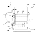
- FIG. 1 is an external view of the OCT device 100.
- the OCT device 100 includes a moving table 102, a measuring unit 103, a face support unit 104, a monitor 106, a control unit 107, and the like.
- the face support unit 104 supports the face of the subject P.
- the face support unit 104 has a forehead pad 104a and a chin rest 104b.
- the forehead of the subject P is brought into contact with the forehead pad 104a.
- the jaw of the subject P is placed on the jaw base 104b.
- the chin rest 104b is provided with a detector 105.
- the detector 105 detects whether or not the jaw of the subject P is placed on the jaw base 104b.
- the detector 105 may be composed of at least one of an optical sensor, a pressure sensor, a load sensor, an ultrasonic sensor, and the like.
- a load sensor is used as the detector 105, and the load sensor detects the load due to the jaw of the subject P being placed on the jaw base 104b.
- the detection result of the detector 105 is output to the control unit 107.
- the monitor 106 is a setting screen for obtaining OCT data by the OCT optical system (for example, a setting screen for setting a scanning position of measurement light, a scanning pattern, a region in the depth direction, etc.), and a tomographic image generated from the OCT data.
- a face image captured by the face imaging optical system 10 an anterior segment image captured by the anterior segment imaging optical system 20, an identifier described later captured by the anterior segment imaging optical system 20, and the like are displayed.
- the monitor 106 may be a touch panel, and the monitor 106 may also serve as an operation unit. For example, by operating the monitor 106, the X moving mechanism and the Z moving mechanism provided on the moving table 102 are driven, and the measuring unit 103 arranged on the upper part of the moving table 102 moves in the left-right direction (X direction) and back and forth. It may be moved in the direction (Z direction). Further, by operating the monitor 106, the Y moving mechanism provided in the measuring unit 103 may be driven, and the measuring unit 103 may be moved in the vertical direction (Y direction).
- FIG. 2 is a schematic view of the internal configuration of the measuring unit 103.
- the measuring unit 103 includes a face imaging optical system 10 (see FIG. 1), an anterior segment imaging optical system 20, an alignment index projection optical system 30, an OCT optical system 40, an observation optical system 50, a fixation induction optical system 60, and the like. Be prepared.
- the face imaging optical system 10 images a face including at least a part of the eye E (left eye and right eye) to be examined.
- the face imaging optical system 10 may include an imaging element (not shown).
- the image sensor captures the face of the subject supported by the face support unit 104.
- the anterior segment imaging optical system 20 images the anterior segment of the eye E to be inspected.
- the anterior segment imaging optical system 20 may include an imaging element 21.
- the image sensor 21 has sensitivity in the infrared region. Further, the image sensor 21 also serves as an image sensor for detecting the alignment index, and images the front eye portion illuminated by the infrared light source 35 and the alignment index.
- the alignment index projection optical system 30 projects the alignment index toward the cornea of the eye E to be inspected.
- the alignment index projection optical system 30 includes a first projection optical system 30a and a second projection optical system 30b.
- the first projection optical system 30a projects an alignment index at infinity toward the cornea of the eye E to be inspected.
- the first projection optical system 30a may include an infrared light source 31 and a collimator lens 32.
- the infrared light source 31 is arranged in a ring shape about the optical axis and emits near-infrared light.
- the collimator lens 32 converts the light emitted from the infrared light source 31 into a parallel luminous flux.
- the second projection optical system 30b projects a finite distance alignment index toward the cornea of the eye E to be inspected.
- the second projection optical system 30b may include an infrared light source 35.
- the infrared light source 35 is arranged in a ring shape at a position different from that of the infrared light source 31 about the optical axis, and emits near-infrared light.
- the light from the second projection optical system 30b is used not only as the alignment light but also as the anterior segment imaging light by the anterior segment imaging optical system 20.
- the OCT optical system 40 detects an interference signal due to the measurement light and the reference light applied to the eye E to be inspected.
- the OCT optical system 40 includes a light source 41, a coupler (optical divider) 42, a scanning unit (for example, an optical scanner) 43, a measurement optical system 44, a detector 45, a reference optical system 46, and the like.
- the light source 41, the measuring optical system 44, the detector 45, and the reference optical system 46 are connected to the coupler 42 by an optical fiber.
- the OCT optical system 40 divides the light emitted from the light source 41 into measurement light and reference light by the coupler 42.
- the measurement light is emitted into the air after passing through the optical fiber, and is guided to the fundus through the scanning unit 43 and the measurement optical system 44.
- the reference light passes through the optical fiber and is guided to the reference optical system 46.
- the measurement light reflected by the fundus of the eye and the reference light reflected by the reflected optical system (for example, a reference mirror) included in the reference optical system 46 (for example, a reference mirror) are returned to the optical fiber through the same path.
- the OCT optical system 40 causes the detector 45 to receive an interference signal (interference light) obtained by combining the measurement light and the reference light.
- the interference signal detected by the detector 45 is output to the control unit 107.
- the observation optical system 50 has a configuration of a so-called scanning laser ophthalmoscope (SLO) for ophthalmology, photographs the fundus of the eye E to be inspected, and acquires an SLO front image thereof.
- the observation optical system 200 may have a so-called fundus camera type configuration. Further, the observation optical system 200 may be an infrared imaging optical system that photographs the eye to be inspected using infrared light.
- the fixation guidance optical system 60 guides the line-of-sight direction of the eye E to be inspected.
- the fixation-guided optical system 60 has a fixation lamp to be presented to the eye E to be inspected, and the presentation position of the fixation lamp may be changed two-dimensionally. As a result, the line of sight of the eye E to be inspected is guided in a plurality of directions, and as a result, the imaging site is changed.
- the control unit 107 includes a general CPU (Central Processing Unit), RAM, ROM, and the like.
- the CPU controls the OCT device 100.
- the RAM temporarily stores various types of information.
- a program or the like for controlling the operation of the OCT device 100 is stored in the ROM.
- the control unit 107 includes a drive unit of a movement mechanism (X movement mechanism, Y movement mechanism, Z movement mechanism), a detector 105, a monitor 106, a light source and an image sensor included in each optical system, a storage unit (memory) 108, and the like. Is electrically connected.
- the storage unit 108 may be a non-transient storage medium that can retain the stored contents even when the power supply is cut off.
- the storage unit 108 may be a hard disk drive, a flash ROM, a detachable USB memory, or the like.
- the storage unit 108 may store information related to settings for obtaining OCT data, OCT data, and the like.
- ⁇ Control operation> The control operation of the OCT apparatus 100 having the above configuration will be described.
- the same examination for the eye to be inspected may be performed under the same conditions as the past examination, such as when observing the progress of the eye E to be inspected.
- such a situation is taken as an example, and a case where an inspection condition is set by using an identifier described later and an inspection is performed on the eye E to be inspected will be described.
- the examiner hands the card to the examinee.
- the examiner reads out the examination conditions at the time of the past examination for the eye E to be examined from an electronic medical record or the like, issues a card printed with an identifier described later, which is created by computerizing the past examination conditions. Give this to the subject.
- the subject follows the instructions of the examiner and heads for the OCT device 100 with the card.
- FIG. 3 is an example of the card 70 that the examiner gives to the examinee.
- the identifier 75 is printed on the card 70 that the examiner gives to the examinee.
- the identifier 75 is associated with an inspection condition set in advance for each subject to perform an inspection on the eye E to be inspected.
- the height of the jaw stand 104b, the moving position of the measuring unit 103 (in other words, the moving amount of the X moving mechanism, the Y moving mechanism, and the Z moving mechanism provided in the measuring unit 103), and imaging for acquiring OCT data.
- At least one of the conditions may be associated with the condition.
- a QR code (registered trademark) is printed as an identifier 75 on the card 70 that the examiner gives to the examinee, and the height of the jaw base 104b, the moving position of the measuring unit 103, and the photographing are performed on the QR code.
- the identifier 75 may be associated with these inspection conditions in advance based on the information obtained when the eye E to be inspected has previously performed the inspection using the OCT device 100.
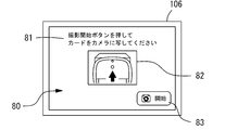
- FIG. 4A and 4B are views showing the screen of the monitor 106.
- FIG. 4A is an example of the guidance screen 80 for guiding the subject.
- FIG. 4B is an example of an imaging screen 90 including an captured image described later.
- the control unit 107 displays a guidance screen 80 for guiding the subject on the monitor 106.
- a message 81 for indicating the content of instructions to the subject, an operation diagram 82 for assisting the operation of the subject, a shooting start switch 83, and the like may be displayed.
- the case where the instruction content to the examinee is displayed as a message 81 is illustrated, but the instruction content to the examiner may be emitted as a voice guide from a speaker (not shown).
- the case of displaying a diagram showing the position of the camera, which will be described later is illustrated as the operation diagram 82, but a series of operations of the subject may be displayed by animation or the like.
- the control unit 107 controls the anterior segment imaging optical system 20 according to the start signal input from the switch, and starts imaging by the imaging element 21. For example, the control unit 107 moves the measurement unit 103 in the Z direction so that the focus of the anterior segment imaging optical system 20 is at a predetermined position (for example, the position of the chin rest 104b) in response to the start signal. .. Further, the control unit 107 sequentially processes the signals output from the image pickup device 21 to generate an image pickup image (live image), and displays the image pickup screen 90 on the monitor 106. On the imaging screen 90, a message 91 for indicating the content of instructions to the subject, a generated captured image 92, a guide mark 93 for aligning the position of the identifier 75, and the like may be displayed.
- control unit 107 controls the anterior segment imaging optical system 20 in response to the start signal input from the shooting start switch 83 has been described as an example, but the present invention is not limited to this.
- the control unit 107 may be configured to control the anterior segment imaging optical system 20 after a certain period of time has elapsed after displaying the guidance screen 80. That is, the image sensor 21 may automatically start imaging when a certain period of time has elapsed after displaying the guidance screen 80.
- FIG. 5 is a diagram showing the operation of the subject.
- the subject positions the card 70 in front of the anterior segment imaging optical system 20 (imaging element 21). For example, the subject positions the card 70 near the chin rest 104b. While checking the imaging screen 90, the subject searches for a state in which the focus of the anterior segment imaging optical system 20 is aligned with the card 70, and copies the identifier 75 so that the identifier 75 fits within the guide mark 93.
- the control unit 107 analyzes the live image, detects that the identifier 75 is included in the guide mark 93, and automatically captures the live image. For example, the control unit 107 searches for the QR code cutout symbol from the live image, recognizes the position of the QR code, and the position coordinates (pixel coordinates) of the QR code and the position coordinates (pixel coordinates) corresponding to the guide mark 93. By comparing with and, it may be detected that the QR code is included in the guide mark 93 and the live image may be automatically captured.
- control unit 107 analyzes the captured live image, reads the identifier 75, and acquires the above-mentioned inspection conditions associated with the identifier 75. For example, the control unit 107 scans the area surrounded by the cutout symbol of the QR code in the captured live image and decodes the read code to acquire the inspection conditions associated with the QR code. Good.
- the control unit 107 drives a Y movement mechanism (not shown) provided on the face support unit 104 based on the inspection conditions acquired from the identifier 75, moves the chin rest 104b in the vertical direction, and adjusts the height thereof. ..
- the control unit 107 sets the jaw base 104b so that the height H (see FIG. 1) from the measurement optical axis of the measurement unit 103 to the jaw base 104b becomes a predetermined height set for each subject. Move it up and down.
- the jaw base 104b is adjusted to the same height as the height of the jaw base 104b when the eye E to be inspected has previously performed an examination using the OCT device 100.
- control unit 107 drives an X movement mechanism, a Y movement mechanism, and a Z movement mechanism (not shown) provided in the measurement unit 103 based on the inspection conditions acquired from the identifier 75, and drives the measurement unit 103 in the left-right direction. Move it in the vertical direction and the Z direction to adjust its position.
- the control unit 107 moves the measurement unit 103 so that the distance D (see FIG. 1) between the measurement unit 103 and the chin rest 104b is a predetermined distance set for each subject.
- the predetermined distance may be the distance when the eye to be inspected E is aligned as described later and the apex position of the cornea of the eye to be inspected E is aligned with the measurement optical axis of the measuring unit 103.
- the measurement unit 103 is adjusted to the same position as the position of the measurement unit 103 when the eye E to be inspected has previously performed an examination using the OCT device 100.
- control unit 107 sets the imaging conditions for photographing the eye E to be inspected and acquiring the OCT data based on the inspection conditions acquired from the identifier 75. For example, the control unit 107 sets the scanning position of the measurement light with respect to the fundus of the eye E to be the same as the scanning position when the eye E has previously performed an examination using the OCT device 100. Further, for example, the control unit 107 uses the scanning pattern of the measurement light on the fundus of the eye E to be inspected (for example, line scan, raster scan, circle scan, radial scan, etc.), and the eye E to be inspected uses the OCT device 100 in the past. Set to the same pattern as the scanning pattern when the inspection was performed. That is, the control unit 107 sets the conditions for photographing the same eye E to be examined under the same imaging conditions as the imaging conditions executed in the past (so-called follow-up imaging conditions).
- the control unit 107 emits a voice announcement (for example, "Please put the chin on the chin rest") from a speaker (not shown) to guide the subject P.
- Subject P sits in front of the OCT device 100 and places his chin on the chin rest 104b according to the instructions.
- the detector 105 provided on the chin rest 104b detects a load from the outside, it converts this load into an electric signal and outputs it to the control unit 107.
- the control unit 107 detects that the jaw of the subject P is placed on the chin rest 104b when an electric signal is input from the detector 105.
- control unit 107 may detect that the jaw of the subject P is placed on the jaw stand 104b when the electric signal from the detector 105 is continuously input for a predetermined time or longer.
- the predetermined time may be a time that can be distinguished from the case where the subject P repositions the jaw on the jaw base 104b. As an example, it may be 5 seconds or longer.
- the control unit 107 can detect that the jaw of the subject P is placed on the jaw stand 104b and is ready to start the examination of the eye E to be inspected.
- the control unit 107 emits a voice announcement (for example, "Please observe the optotype") from a speaker (not shown) to cause the subject P to observe the optotype.
- a voice announcement for example, "Please observe the optotype”
- the subject P gazes at the fixation target displayed on the monitor (not shown) provided in the measuring unit 103.
- the control unit 107 of the OCT device 100 emits a voice announcement (for example, "Start the inspection. Press the start switch.") From a speaker (not shown) to start the inspection for the subject P. Operate a switch (not shown).
- the subject P operates the switch according to the instruction.
- the control unit 107 controls the anterior segment imaging optical system 20 according to the start signal input from the switch, and starts imaging by the imaging element 21. Further, the control unit 107 controls the alignment index projection optical system 30 according to the start signal input from the switch, turns on the infrared light source 31 and the infrared light source 35, and projects the alignment index on the cornea of the eye E to be inspected. To do.
- the control unit 107 generates an image (anterior eye image) based on the signal output from the image sensor 21, and uses the alignment index image to position the corneal apex of the eye E to be inspected with respect to the measurement optical axis of the measurement unit 103.
- misalignment approximately the position of the apex of the cornea
- the moving position of the measuring unit 103 is finely adjusted. It can be suppressed to the extent that it does.
- control unit 107 When the alignment between the OCT device 100 and the eye E to be inspected is completed, the control unit 107 performs optimization control (for example, adjustment of the optical path length) for observing the fundus portion of the eye E to be inspected desired by the examiner with high sensitivity and high resolution. , Focus adjustment, polarization state adjustment, etc.), and OCT data acquisition is executed under the inspection conditions set by using the identifier 75.
- optimization control for example, adjustment of the optical path length
- the optometry apparatus in this embodiment includes an imaging optical system for imaging the eye to be inspected and a setting means for setting inspection conditions of the apparatus, and is inspected by the imaging optical system.
- an identifier associated with an individual inspection condition preset for each person is imaged, the inspection condition of the device based on the individual inspection condition is set.
- the examination conditions suitable for the subject are automatically set, so that it is not necessary to set the examination conditions for each subject as in the conventional case, and the examination for the eye to be examined can be efficiently performed.
- the imaging optical system also serves as an imaging of the eye to be inspected and an imaging of an identifier, it is not necessary to provide a new member in the apparatus, and the apparatus can be easily configured.
- the anterior segment imaging optical system 20 serves as both an optical system for imaging the eye to be inspected for alignment and an optical system for imaging the identifier 75, thereby facilitating the apparatus. It can be configured as such.
- the optometry apparatus in this embodiment uses an anterior segment imaging optical system that images the anterior segment of the eye to be inspected to image an identifier. That is, the anterior segment imaging optical system also serves as an optical system for imaging an identifier. As a result, the identifier can be imaged with a simple configuration.
- the optometry device in this embodiment captures a two-dimensional code as an identifier.
- a two-dimensional code as an identifier.
- the optometry device in this embodiment sets the inspection conditions of the optometry device so that the inspection conditions are the same as the past inspection conditions for the eye to be inspected based on the individual inspection conditions associated with the identifier. ..
- the optometry device in this embodiment sets the inspection conditions of the optometry device so that the inspection conditions are the same as the past inspection conditions for the eye to be inspected based on the individual inspection conditions associated with the identifier. ..
- the optometry device in the present embodiment includes a face support unit for supporting at least a part of the face of the subject, and the position of the face support unit is based on the individual examination conditions associated with the identifier.
- the position of the forehead pad that brings the subject's forehead into contact, the chin rest on which the subject's chin is placed, and the like are set.
- the positional relationship between the eye to be examined and the device is kept constant, so that the subject does not have to reposition the face on the forehead or the chin rest and readjust. The inspection can proceed efficiently.
- the anterior segment imaging optical system 20 that images the anterior segment of the eye E to be inspected is used to image the identifier 75 associated with the inspection conditions preset for each subject.
- the face imaging optical system 10 that images the face of the eye E to be inspected to take an image of the identifier 75 associated with the inspection conditions preset for each subject. is there.
- the control unit 107 controls the face imaging optical system 10 to image the identifier 75
- the setting based on the inspection conditions associated with the identifier 75 may be made. Good.
- the measuring unit when the identifier 75 is imaged by the anterior segment imaging optical system 20, the measuring unit is previously measured so that the focus of the anterior segment imaging optical system 20 comes to a predetermined position (position of the jaw stand 104b).
- a predetermined position position of the jaw stand 104b.
- the configuration in which the 103 is moved in the Z direction has been described as an example, but the present invention is not limited to this.
- the focus is automatically adjusted by moving the measuring unit 103 in the Z direction with respect to the identifier 75 presented by the subject P. May be.
- the configuration in which the identifier 75 is imaged in monochrome by providing the image pickup element 21 having the sensitivity in the infrared region in the anterior segment imaging optical system 20 has been described as an example, but the present invention is not limited to this. ..
- the anterior segment imaging optical system 20 may include an imaging element having sensitivity in the visible region, and may be capable of imaging the identifier 75 in color.
- a color code capable of expressing information in an array of colors may be used, and more information may be associated with the identifier 75.
- the identifier 75 may be associated with a predetermined inspection condition for the eye E to be inspected.
- the height of the jaw stand 104b may be associated with the identifier 75.
- the control unit 107 may move the jaw base 104b in the vertical direction. Further, in this case, the control unit 107 may move the jaw base 104b in the vertical direction and adjust the movement position of the measurement unit 103 based on the movement amount of the jaw base 104b. That is, the jaw base 104b may be directly controlled based on the predetermined inspection conditions associated with the identifier 75, and the measurement unit 103 may be indirectly controlled in conjunction with the control of the jaw base 104b.
- the configuration in which the identifier 75 is associated with the inspection conditions when the eye E to be inspected has previously performed the inspection using the OCT device 100 has been described as an example, but the present invention is not limited to this.
- the identifier 75 may be associated with the inspection conditions when the eye E to be inspected performs the inspection using a device different from the OCT device 100.
- the position of the chin rest when the examination is performed using a device different from the OCT device 100 may be associated.
- the configuration in which the identifier 75 is associated with the imaging conditions related to the scanning of the measurement light in the OCT apparatus 100 has been described as an example, but the present invention is not limited to this.
- the identifier 75 may be associated with a shooting condition (for example, at least one of an optical path length difference, a focus, a polarization state, etc.) different from the scanning of the measurement light.
- a shooting condition for example, at least one of an optical path length difference, a focus, a polarization state, etc.
- the above-mentioned optimization control in the examination of the eye E to be inspected can be omitted, and the examination can proceed more efficiently.
- the identifier 75 may be associated with both a shooting condition related to scanning of the measurement light and a shooting condition different from the scanning of the measurement light.
- the OCT device 100 in this embodiment is a new identifier associated with the inspection conditions for examining the eye to be inspected by the OCT device 100, and outputs an identifier that can be read by a device different from the OCT device 100. You may.
- the inspection conditions of the device other than the OCT device 100 are set based on the inspection conditions associated with the new identifier, and the inspection conditions of the other device and the inspection conditions of the OCT device 100 are set to be the same. May be done.
- control unit 107 of the OCT device 100 may print a new identifier on paper with a printer or the like (not shown). Further, as an example, the control unit 107 of the OCT device 100 may display a new identifier on the monitor 106.
- the subject P acquires a paper on which a new identifier is printed (or an image of the identifier captured by a terminal device or the like), heads to another device, and has the identifier read by another device. Even if the control unit of another device sets the inspection conditions of the device other than the OCT device 100 to the same inspection conditions as when the OCT device 100 is used, based on the inspection conditions associated with the identifier. Good.
- the height of the jaw base of a device different from the OCT device 100 may be set to the same height as the height of the jaw base when the OCT device 100 is used. As a result, it is not necessary to set the inspection conditions in the device used next to the OCT device 100, and the inspection for the eye to be inspected can be efficiently advanced.
- the inspection condition for inspecting the eye to be inspected by the OCT apparatus 100 is associated with a new identifier
- the present invention is not limited to this.
- the inspection conditions for inspecting the eye to be inspected by the OCT apparatus 100 and the inspection results may be associated with a new identifier.
- the inspection condition may be output as an identifier stored
- the inspection result may be output to the cloud (server)
- a record such as an electronic medical record may be updated.
- the OCT device 100 in this embodiment may have a configuration in which at least a part of its operation is restricted when the examination for the eye E to be inspected is not performed.
- an operation related to alignment between the eye E to be examined and the device, an operation related to imaging of the eye E to be examined, and the like can be executed. It may be restricted.
- the control unit 107 controls the anterior eye portion imaging optical system 20 to image the identifier 75 and reads the inspection conditions from the identifier 75, the restriction on the operation of the device is released and the eye E to be inspected is released.
- the configuration may be such that the inspection can be started.
- the OCT device 100 in the present embodiment may be configured to input authentication information for authenticating the subject in addition to imaging the identifier 75 using the anterior segment imaging optical system 20.
- the authentication information may be an ID, a personal identification number, a password, or the like given to each subject.
- the authentication information may be imaged using the anterior segment imaging optical system 20 as an identifier that can be recognized as an image.
- the control unit 107 determines whether or not the identifier 75 associated with the inspection conditions for each subject and the authentication information given for each subject match, and match. At that time, the inspection condition associated with the identifier 75 may be set to execute the inspection for the eye E to be inspected.
Landscapes
- Life Sciences & Earth Sciences (AREA)
- Health & Medical Sciences (AREA)
- Medical Informatics (AREA)
- Biophysics (AREA)
- Ophthalmology & Optometry (AREA)
- Engineering & Computer Science (AREA)
- Biomedical Technology (AREA)
- Heart & Thoracic Surgery (AREA)
- Physics & Mathematics (AREA)
- Molecular Biology (AREA)
- Surgery (AREA)
- Animal Behavior & Ethology (AREA)
- General Health & Medical Sciences (AREA)
- Public Health (AREA)
- Veterinary Medicine (AREA)
- Eye Examination Apparatus (AREA)
Abstract
被検者の被検眼を検査する検眼装置であって、被検眼を撮像するための撮像光学系と、検眼装置の検査条件を設定する設定手段と、を備え、撮像光学系は、被検者毎に予め設定される個別検査条件が対応付けされた識別子を撮像可能であって、設定手段は、撮像光学系によって識別子が撮像された場合に、識別子に対応付けされた個別検査条件に基づいて、検眼装置の検査条件を設定する。これによって、被検眼に対する検査を効率よく行うことができる。
Description
本開示は、被検眼を検査する検眼装置及び検眼プログラムに関する。
被検眼を検査する検眼装置として、被検眼の眼底断層画像を撮影する眼科撮影装置(特許文献1)、被検眼の光学特性を他覚的に測定する他覚式検眼装置(特許文献2)、被検眼の光学特性を自覚的に測定する自覚式検眼装置(特許文献3)、等が用いられている。
検者は、検眼装置を用いて被検眼を検査する際に、被検者に関する情報の入力や検索を行い、被検眼と装置の位置関係、過去と同一の検査条件、等を設定して、検査を開始している。検者にとって、このような操作は手間であり、検査を効率よく進めることが難しかった。
本開示は、上記従来技術に鑑み、被検眼に対する検査を効率よく行うことができる検眼装置及び検眼プログラムを提供することを技術課題とする。
本開示の第1態様に係る検眼装置は、被検者の被検眼を検査する検眼装置であって、前記被検眼を撮像するための撮像光学系と、前記検眼装置の検査条件を設定する設定手段と、を備え、前記撮像光学系は、前記被検者毎に予め設定される個別検査条件が対応付けされた識別子を撮像可能であって、前記設定手段は、前記撮像光学系によって前記識別子が撮像された場合に、前記識別子に対応付けされた前記個別検査条件に基づいて、前記検眼装置の前記検査条件を設定する。
本開示の第2態様に係る検眼プログラムは、被検者の被検眼を検査する検眼装置にて用いる検眼プログラムであって、前記検眼装置のプロセッサに実行されることで、前記被検眼を撮像するための撮像ステップと、前記検眼装置の検査条件を設定する設定ステップと、を備え、前記撮像ステップは、前記被検者毎に予め設定される個別検査条件が対応付けされた識別子を撮像可能なステップであって、前記設定ステップは、前記撮像ステップによって前記識別子が撮像された場合に、前記識別子に対応付けされた前記個別検査条件に基づいて、前記検眼装置の前記検査条件を設定することを、前記検眼装置に実行させる。
本開示の第3態様に係る検眼装置は、被検者の被検眼を検査する検眼装置であって、前記被検眼を撮像するための撮像光学系を備えた別の検眼装置における前記撮像光学系によって読み取られる識別子であって、前記撮像光学系に読み取られることで、前記別の検眼装置の検査条件を、前記被検者毎に予め設定される個別検査条件に設定可能とする識別子を出力する出力手段を備える。
本開示の第4態様に係る検眼装置は、被検者の被検眼を検査する検眼装置であって、別の検眼装置によって読み取られる識別子であって、前記別の検眼装置に読み取られることで、前記別の検眼装置の検査条件を、前記被検者毎に予め設定される個別検査条件に設定可能とする識別子を出力する出力手段を備える。
<概要>
本開示における実施形態の概要について説明する。以下の<>にて分類された項目は、独立または関連して利用されうる。
本開示における実施形態の概要について説明する。以下の<>にて分類された項目は、独立または関連して利用されうる。
<検眼装置>
本実施形態に係る検眼装置は、被検者の被検眼を検査する装置である。
本実施形態に係る検眼装置は、被検者の被検眼を検査する装置である。
検眼装置は、被検眼を撮影することで、被検眼を検査する装置でもよい。例えば、検眼装置は、被検眼の前眼部を撮影して、被検眼の前眼部画像データ、被検眼の角膜形状、等を取得する眼科撮影装置でもよい。また、例えば、検眼装置は、被検眼の眼底を撮影して、被検眼の眼底正面画像データ、被検眼の眼底断層画像データ、等を取得する眼科撮影装置でもよい。
検眼装置は、被検眼を測定することで、被検眼を検査する装置でもよい。一例として、検眼装置は、被検眼の光学特性を他覚的に測定する他覚式検眼装置でもよい。例えば、被検眼の光学特性として、被検眼の眼屈折力(例えば、球面度数、円柱度数、乱視軸角度、等)、両眼視機能(例えば、斜位量、立体視機能、等)、コントラスト感度、等を他覚的に測定する他覚式検眼装置でもよい。また、一例として、検眼装置は、被検眼の光学特性を自覚的に測定する自覚式検眼装置でもよい。例えば、被検眼の光学特性として、被検眼の眼屈折力等を自覚的に測定する自覚式検眼装置でもよい。また、一例として、検眼装置は、被検者の視認による応答を得て、被検眼の視野を測定する検眼装置でもよい。
より詳細には、検眼装置として、光干渉断層計(Optical Coherence Tomography:OCT)、走査型レーザ検眼鏡、眼底カメラ、眼圧測定装置、眼軸長測定装置、角膜形状測定装置、角膜曲率測定装置、超音波検眼装置、眼屈折力測定装置、フォロプタ、視野計、等の少なくともいずれかが挙げられる。
なお、本実施形態では、このような検眼装置として、光干渉断層計(例えば、OCT装置100)を例に挙げて説明する。光干渉断層計は、タイムドメインOCT(Time Domain OCT:TD-OCT)であってもよいし、フーリエドメインOCT(Fourier Domain OCT:FD-OCT)であってもよい。FD-OCTは、スペクトルドメインOCT(Spectral Domain OCT:SD-OCT)や波長掃引式OCT(Swept Source OCT:SS-OCT)が代表的である。
<検査手段>
検眼装置は、検査手段(例えば、OCT光学系40)を備えてもよい。検査手段は、被検眼を検査するための検査手段である。検査手段は、光を受光することで被検眼を検査する検査系を備えてもよい。この場合、検査系は、被検眼を撮像するための撮像光学系であってもよい。また、この場合、検査系は、被検眼を測定するための測定光学系であってもよい。検査手段は、撮像光学系と測定光学系の少なくともいずれかを備える構成としてもよい。
検眼装置は、検査手段(例えば、OCT光学系40)を備えてもよい。検査手段は、被検眼を検査するための検査手段である。検査手段は、光を受光することで被検眼を検査する検査系を備えてもよい。この場合、検査系は、被検眼を撮像するための撮像光学系であってもよい。また、この場合、検査系は、被検眼を測定するための測定光学系であってもよい。検査手段は、撮像光学系と測定光学系の少なくともいずれかを備える構成としてもよい。
検査手段は、光を受光することで被検眼を検査する検査系に限定されず、超音波を受信することで被検眼を検査する検査系であってもよい。この場合、検査系は、超音波を出射してその反射波を検出することにより被検眼を測定するための超音波測定系であってもよい。
なお、検査手段としては、光を受光することで被検眼を検査する検査系と、超音波を受信することで被検眼を検査する検査系と、のいずれかを備える構成としてもよい。もちろん、光を受光することで被検眼を検査する検査系と、超音波を受信することで被検眼を検査する検査系と、をどちらも備える構成としてもよい。
<撮像光学系>
検眼装置は、撮像光学系を備える。撮像光学系は、被検眼を撮像するための撮像光学系である。例えば、撮像光学系は、左眼及び右眼のいずれかを撮像する構成としてもよい。また、例えば、撮像光学系は、左眼及び右眼をどちらも撮像する構成としてもよい。本実施形態においては、検眼装置が備える制御部(例えば、制御部107)に、撮像光学系が制御されることで、被検眼が撮像される。
検眼装置は、撮像光学系を備える。撮像光学系は、被検眼を撮像するための撮像光学系である。例えば、撮像光学系は、左眼及び右眼のいずれかを撮像する構成としてもよい。また、例えば、撮像光学系は、左眼及び右眼をどちらも撮像する構成としてもよい。本実施形態においては、検眼装置が備える制御部(例えば、制御部107)に、撮像光学系が制御されることで、被検眼が撮像される。
撮像光学系は、被検眼を含むように撮像するための撮像光学系であってもよい。一例として、被検者の顔を撮像するための顔撮像光学系(例えば、顔撮像光学系10)を用いてもよい。この場合、被検者の顔が、左眼及び右眼の少なくともいずれかを含むように撮像されてもよい。また、一例として、被検眼の前眼部を撮像するための前眼部撮像光学系(例えば、前眼部撮像光学系20)を用いてもよい。また、一例として、被検眼の眼底を撮像するための眼底撮像光学系を用いてもよい。
本実施形態において、撮像光学系は、被検者毎に予め設定される個別の検査条件が対応付けされた識別子を撮像可能としてもよい。つまり、撮像光学系が、被検眼の撮像と識別子の撮像で兼用されてもよい。このような、撮像光学系を兼用して使い分ける構成とすることで、装置に新たな部材を設けることなく、識別子を容易な構成で撮像できる。
例えば、撮像光学系が、被検眼の顔を撮像する顔撮像光学系である場合、顔撮像光学系が、識別子を撮像可能としてもよい。すなわち、顔撮像光学系が、被検眼の顔を撮像するための撮像光学系と、識別子を撮像するための撮像光学系と、を兼用してもよい。同様に、例えば、撮像光学系が、被検眼の前眼部を撮像する前眼部撮像光学系である場合、前眼部撮像光学系が、識別子を撮像可能としてもよい。すなわち、前眼部撮像光学系が、被検眼の前眼部を撮像するための撮像光学系と、識別子を撮像するための撮像光学系と、を兼用してもよい。同様に、例えば、撮像光学系が、被検眼の眼底を撮像する眼底撮像光学系である場合、眼底撮像光学系が、識別子を撮像可能としてもよい。すなわち、眼底撮像光学系が、被検眼の眼底を撮像するための撮像光学系と、識別子を撮像するための撮像光学系と、を兼用してもよい。
<検査条件>
本実施形態において、被検者毎に予め設定される個別の検査条件とは、被検者の被検眼を検査するための、被検者毎に異なる検査条件である。例えば、検査条件は、被検者(被検眼)に合わせて設定される、被検眼を測定するための測定条件であってもよい。また、例えば、被検者(被検眼)に合わせて設定される、被検眼を撮影するための撮影条件であってもよい。
本実施形態において、被検者毎に予め設定される個別の検査条件とは、被検者の被検眼を検査するための、被検者毎に異なる検査条件である。例えば、検査条件は、被検者(被検眼)に合わせて設定される、被検眼を測定するための測定条件であってもよい。また、例えば、被検者(被検眼)に合わせて設定される、被検眼を撮影するための撮影条件であってもよい。
例えば、検査条件は、被検者に関する情報(例えば、身長、顔の大きさ、眼の形状、左眼から右眼までの距離、等)に基づいて予め設定される条件でもよい。また、例えば、検査条件は、被検眼に対する過去の検査条件に基づいて予め設定される条件でもよい。なお、過去の検査条件とは、同一の装置を用いて過去に検査を行った際の条件としてもよいし、異なる装置を用いて過去に検査を行った際の条件としてもよい。この場合、検査条件は、識別子を更新することによって、あるいは、識別子に関連付けられたクラウドやサーバの情報を更新することによって、適宜変更されてもよい。
検査条件は、被検者(被検眼)と装置の位置関係を設定するための条件でもよい。この場合、検査条件は、被検者に対する装置の位置を設定するための条件としてもよい。一例として、被検者の目線の高さに合わせた装置の移動位置を設定する条件であってもよい。また、この場合、検査条件は、検眼装置が備える被検者の顔の少なくとも一部を支持するための顔支持ユニットの位置を設定するための条件としてもよい。一例として、被検者の額を当接させる額当ての位置を設定する条件であってもよい。また、一例として、被検者の顎を載置する顎台の位置(顎台の高さ)を設定する条件であってもよい。
検査条件は、被検者(被検眼)に対する検査手段の検査条件を設定するための条件でもよい。この場合、検査条件は、検査手段が備える光学系の各部について調整可能な条件であって、検査結果(例えば、信号の取得、撮像画像の取得、等)に影響する条件であってもよい。一例としては、光源の出力(光量)、光の走査位置や走査パターン、光学系における光学部材の配置、光学系における光学部材のパラメータ、撮像素子からの信号の増幅率(ゲイン)、視度の補正量(フォーカス)、等の少なくともいずれかが挙げられる。また、この場合、検査条件は、検査手段が備える光学系により得られた検査結果を解析する際の処理に関する条件であってもよい。一例としては、輝度の補正量(ブライトネス及びコントラスト等)、撮像画像における各部の位置の補正量、等の少なくともいずれかが挙げられる。
なお、光干渉断層計において、被検者毎に予め設定される個別の検査条件としては、上記の条件の他、測定光と参照光の光路長差、偏光状態、等の少なくともいずれかが含まれてもよい。
<識別子>
本実施形態において、識別子には、上記の個別の検査条件が対応付けられてもよい。例えば、識別子に情報を格納することで、識別子に個別の検査条件を対応付ける構成としてもよい。また、例えば、識別子と、予めクラウドやサーバに保存された情報と、を関連付けておくことで、識別子に個別の検査条件を対応付ける構成としてもよい。
本実施形態において、識別子には、上記の個別の検査条件が対応付けられてもよい。例えば、識別子に情報を格納することで、識別子に個別の検査条件を対応付ける構成としてもよい。また、例えば、識別子と、予めクラウドやサーバに保存された情報と、を関連付けておくことで、識別子に個別の検査条件を対応付ける構成としてもよい。
識別子としては、被検者の生体情報(例えば、虹彩、指紋、等)とは異なる情報であって、画像として認識することが可能な情報を用いることができる。例えば、文字列、1次元コード(例えば、バーコード等)、2次元コード(例えば、QRコード(登録商標)、カラーコード、等)等を利用してもよい。例えば、識別子として生体情報を利用する場合、虹彩パターンや指紋パターンは多様であるため、解析処理が複雑になってしまうことがある。しかし、識別子に文字列やコードを利用する場合には、これらを解析しやすく、対応付けられた検査条件を容易に取得することができる。
なお、本実施形態における識別子には、少なくとも個別の検査条件が対応付けられていればよく、検査条件に加えて、検査条件とは異なる情報が対応付けられていてもよい。一例として、識別子には、検査条件とともに被検者情報が対応付けられていてもよい。被検者情報としては、被検者の個人情報(例えば、氏名、性別、年齢、等の少なくともいずれか)、被検者毎に付与されるID、等が挙げられる。
このような被検者毎の識別子は、被検者が所持できるように出力されていてもよい。例えば、被検者用の表示手段(一例として、携帯端末、タブレット端末、スマートフォン、等の少なくともいずれか)へ表示されてもよい。また、例えば、プリンタ等を用いて紙等に印刷されてもよい。
<設定手段>
検眼装置は、設定手段(例えば、制御部107)を備える。設定手段は、検眼装置の検査条件を設定する。例えば、設定手段は、撮像光学系によって識別子が撮像された場合に、識別子に対応付けられた個別の検査条件に基づいて、検眼装置の検査条件を設定する。これによって、被検者に適した検査条件が自動的に設定され、被検眼に対する検査を効率よく行うことができる。
検眼装置は、設定手段(例えば、制御部107)を備える。設定手段は、検眼装置の検査条件を設定する。例えば、設定手段は、撮像光学系によって識別子が撮像された場合に、識別子に対応付けられた個別の検査条件に基づいて、検眼装置の検査条件を設定する。これによって、被検者に適した検査条件が自動的に設定され、被検眼に対する検査を効率よく行うことができる。
本実施形態において、識別子には、前述のように、情報の格納、あるいは、クラウドやサーバに保存された情報との関連付け、等によって、個別の検査条件が対応付けられている。例えば、識別子に情報が格納されている場合、設定手段は、識別子を含む画像を解析処理することで、識別子に対応付けられた個別の検査条件を直接的に読み取ってもよい。また、例えば、識別子にクラウドやサーバに保存された情報が関連付けられている場合、設定手段は、識別子を含む画像を解析処理するとともに、解析結果に基づいて該当の情報を呼び出してもよい。例えば、有線通信(例えば、光ファイバー、有線LAN、等)及び無線通信(例えば、Wi-Fi(登録商標)、Bluetooth(登録商標)、等)の少なくともいずれかによって、該当の情報を呼び出してもよい。設定手段は、識別子に対応付けられた個別の検査条件を、このように直接的あるいは間接的に取得することで、検査条件を設定してもよい。
設定手段は、被検者の個別の検査条件に基づいて、被検眼に対する過去の検査条件と同一の検査条件となるように、検眼装置の検査条件を設定する構成としてもよい。例えば、設定手段は、被検者の個別の検査条件に基づいて、被検者(あるいは、被検眼)と装置の位置関係が、過去と同一の位置関係となるように設定してもよい。一例として、被検者(被検眼)と、額当てや顎台と、の位置関係が、過去と同一の位置関係となるように設定してもよい。被検者(あるいは、被検眼)に対する検査手段の検査条件を、過去と同一の検査条件となるように設定してもよい。一例として、被検眼を撮像するための撮像条件、被検眼を測定するための測定条件、検査結果を解析処理するための処理条件、等の少なくともいずれかの条件を、過去と同一の検査条件となるように設定してもよい。これによって、同一の被検眼に対する検査の度に、装置を同じ条件に設定する手間が省け、検査を効率的に行うことができる。
<出力手段>
検眼装置は、出力手段(例えば、制御部107)を備える。出力手段は、検眼装置とは異なる別の検眼装置の検査条件を、被検者毎に予め設定される個別の検査条件に設定可能とする識別子を出力する。
検眼装置は、出力手段(例えば、制御部107)を備える。出力手段は、検眼装置とは異なる別の検眼装置の検査条件を、被検者毎に予め設定される個別の検査条件に設定可能とする識別子を出力する。
検眼装置とは異なる別の検眼装置は、識別子を読み取るための読取手段を備えていてもよい。この場合、検眼装置の出力手段は、別の検眼装置によって読み取られる識別子であって、別の検眼装置に読み取られることで、別の検眼装置の検査条件を個別の検査条件に設定可能とする識別子を出力してもよい。例えば、検眼装置とは異なる別の検眼装置は、読取手段として、被検眼を撮像するための撮像光学系を兼用する構成であってもよい。この場合、検眼装置の出力手段は、別の検眼装置における撮像光学系によって読み取られる識別子であって、撮像光学系に読み取られることで、別の検眼装置の検査条件を個別の検査条件に設定可能とする識別子を出力してもよい。また、例えば、検眼装置とは異なる別の検眼装置は、読取手段として、別途、スキャナやリーダーを備える構成であってもよい。この場合、検眼装置の出力手段は、別の検眼装置におけるスキャナやリーダーによって読み取られる識別子であって、スキャナやリーダーに読み取られることで、別の検眼装置の検査条件を個別の検査条件に設定可能とする識別子を出力してもよい。例えば、このような構成であれば、被検眼に対して複数の検眼装置を用いた検査を実行する場合等、次の検査装置にて検査条件を設定する必要がなくなり、検査を効率よく進めることができる。
例えば、出力手段は、表示手段への表示、プリンタを用いた印刷、等の少なくともいずれかによって、識別子を出力してもよい。この場合、出力手段によって出力された識別子には、検査条件等の情報が格納されてもよい。検眼装置とは異なる別の検眼装置は、このような識別子を読み取り、識別子に格納された個別の検査条件に基づいて、検査条件を設定してもよい。
なお、出力手段は、表示手段への表示やプリンタを用いた印刷等による出力のみに限定されない。例えば、出力手段は、識別子を表示や印刷により出力するとともに、クラウドやサーバ等に検査条件を出力し、識別子と検査条件とを関連付けて記憶させてもよい。この場合、検眼装置とは異なる別の検眼装置は、このような識別子を読み取り、識別子に関連付けられた個別の検査条件をクラウド(サーバ)から呼び出すことで取得し、個別の検査条件に基づいて検査条件を設定してもよい。
なお、本開示は、本実施形態に記載した検眼装置に限定されない。例えば、上記の実施形態の機能を行う端末制御ソフトウェア(プログラム)を、ネットワークまたは各種の記憶媒体等を介して検眼装置に供給し、検眼装置の制御部(例えば、CPU)が、プログラムを読み出して実行することも可能である。
<実施例>
典型的な実施形態の1つである実施例について説明する。
典型的な実施形態の1つである実施例について説明する。
検眼装置は、被検者の被検眼を検査するために用いる。本実施例では、検眼装置として、眼科撮影装置を例示する。眼科撮影装置は、いわゆる眼科用光干渉断層計の構成を備えたOCT装置であってもよい。以下では、検眼装置をOCT装置と称して説明する。
<OCT装置外観>
図1は、OCT装置100の外観図である。OCT装置100は、移動台102、測定部103、顔支持ユニット104、モニタ106、制御部107、等を備える。
図1は、OCT装置100の外観図である。OCT装置100は、移動台102、測定部103、顔支持ユニット104、モニタ106、制御部107、等を備える。
顔支持ユニット104は、被検者Pの顔を支持する。顔支持ユニット104は、額当て104aと、顎台104bと、を有する。額当て104aには、被検者Pの額が当接される。顎台104bには、被検者Pの顎が載置される。顎台104bには、検出器105が設けられる。
検出器105は、被検者Pの顎が顎台104bに載置されたか否かを検出する。検出器105は、光センサ、圧力センサ、荷重センサ、超音波センサ、等の少なくともいずれかにより構成されてもよい。例えば、本実施例では、検出器105として荷重センサが用いられ、荷重センサによって、被検者Pの顎が顎台104bに載置されたことによる荷重が検出される。検出器105の検出結果は、制御部107に出力される。
モニタ106は、OCT光学系によりOCTデータを得るための設定画面(例えば、測定光の走査位置、走査パターン、深さ方向の領域、等を設定する設定画面)、OCTデータから生成される断層画像、顔撮像光学系10により撮像される顔画像、前眼部撮像光学系20により撮像される前眼部画像、前眼部撮像光学系20により撮像される後述の識別子、等を表示する。
モニタ106はタッチパネルであってもよく、モニタ106が操作部を兼ねてもよい。例えば、モニタ106を操作することで、移動台102に設けられたX移動機構とZ移動機構が駆動し、移動台102の上部に配置された測定部103が、左右方向(X方向)及び前後方向(Z方向)に移動されてもよい。また、モニタ106を操作することで、測定部103に設けられたY移動機構が駆動し、測定部103が、上下方向(Y方向)に移動されてもよい。
<測定部>
図2は、測定部103における内部構成の概略図である。測定部103は、顔撮像光学系10(図1参照)、前眼部撮像光学系20、アライメント指標投影光学系30、OCT光学系40、観察光学系50、固視誘導光学系60、等を備える。
図2は、測定部103における内部構成の概略図である。測定部103は、顔撮像光学系10(図1参照)、前眼部撮像光学系20、アライメント指標投影光学系30、OCT光学系40、観察光学系50、固視誘導光学系60、等を備える。
<顔撮像光学系>
顔撮像光学系10は、被検眼E(左眼及び右眼)の少なくとも一部を含む顔を撮像する。顔撮像光学系10は、図示なき撮像素子を備えてもよい。撮像素子は、顔支持ユニット104に支持された被検者の顔を撮像する。
顔撮像光学系10は、被検眼E(左眼及び右眼)の少なくとも一部を含む顔を撮像する。顔撮像光学系10は、図示なき撮像素子を備えてもよい。撮像素子は、顔支持ユニット104に支持された被検者の顔を撮像する。
<前眼部撮像光学系>
前眼部撮像光学系20は、被検眼Eの前眼部を撮像する。前眼部撮像光学系20は、撮像素子21を備えてもよい。撮像素子21は、赤外域の感度をもつ。また、撮像素子21は、アライメント指標検出用の撮像素子を兼ね、赤外光源35により照明された前眼部とアライメント指標を撮像する。
前眼部撮像光学系20は、被検眼Eの前眼部を撮像する。前眼部撮像光学系20は、撮像素子21を備えてもよい。撮像素子21は、赤外域の感度をもつ。また、撮像素子21は、アライメント指標検出用の撮像素子を兼ね、赤外光源35により照明された前眼部とアライメント指標を撮像する。
<アライメント指標投影光学系>
アライメント指標投影光学系30は、被検眼Eの角膜に向けてアライメント指標を投影する。アライメント指標投影光学系30は、第1投影光学系30a及び第2投影光学系30bを備える。第1投影光学系30aは、被検眼Eの角膜に向けて無限遠のアライメント指標を投影する。第1投影光学系30aは、赤外光源31とコリメータレンズ32を備えてもよい。赤外光源31は、光軸を中心としてリング状に配置され、近赤外光を発する。コリメータレンズ32は、赤外光源31から発せられた光を平行光束にする。第2投影光学系30bは、被検眼Eの角膜に向けて有限遠のアライメント指標を投影する。第2投影光学系30bは、赤外光源35を備えてもよい。赤外光源35は、光軸を中心として赤外光源31とは異なる位置でリング状に配置され、近赤外光を発する。なお、第2投影光学系30bによる光は、アライメント光として用いられるとともに、前眼部撮像光学系20による前眼部撮像光としても用いられる。
アライメント指標投影光学系30は、被検眼Eの角膜に向けてアライメント指標を投影する。アライメント指標投影光学系30は、第1投影光学系30a及び第2投影光学系30bを備える。第1投影光学系30aは、被検眼Eの角膜に向けて無限遠のアライメント指標を投影する。第1投影光学系30aは、赤外光源31とコリメータレンズ32を備えてもよい。赤外光源31は、光軸を中心としてリング状に配置され、近赤外光を発する。コリメータレンズ32は、赤外光源31から発せられた光を平行光束にする。第2投影光学系30bは、被検眼Eの角膜に向けて有限遠のアライメント指標を投影する。第2投影光学系30bは、赤外光源35を備えてもよい。赤外光源35は、光軸を中心として赤外光源31とは異なる位置でリング状に配置され、近赤外光を発する。なお、第2投影光学系30bによる光は、アライメント光として用いられるとともに、前眼部撮像光学系20による前眼部撮像光としても用いられる。
<OCT光学系>
OCT光学系40は、被検眼Eに照射された測定光と参照光による干渉信号を検出する。OCT光学系40は、光源41、カップラー(光分割器)42、走査部(例えば、光スキャナ)43、測定光学系44、検出器45、参照光学系46、等を備える。光源41、測定光学系44、検出器45、及び参照光学系46は、光ファイバでカップラー42に繋がれている。
OCT光学系40は、被検眼Eに照射された測定光と参照光による干渉信号を検出する。OCT光学系40は、光源41、カップラー(光分割器)42、走査部(例えば、光スキャナ)43、測定光学系44、検出器45、参照光学系46、等を備える。光源41、測定光学系44、検出器45、及び参照光学系46は、光ファイバでカップラー42に繋がれている。
OCT光学系40は、光源41から出射した光を、カップラー42によって測定光と参照光に分割する。測定光は、光ファイバを通過した後に空気中へ出射され、走査部43及び測定光学系44を介して、眼底に導かれる。参照光は、光ファイバを通過して、参照光学系46に導かれる。眼底にて反射された測定光と、参照光学系46が備える図示なき反射光学系(例えば、参照ミラー)に反射された参照光と、は同様の経路を経て光ファイバに戻される。OCT光学系40は、測定光と参照光の合成による干渉信号(干渉光)を、検出器45に受光させる。検出器45が検出した干渉信号は、制御部107に出力される。
<観察光学系>
観察光学系50は、いわゆる眼科用走査型レーザ検眼鏡(Scanning Laser Ophthalmoscope:SLO)の構成をもち、被検眼Eの眼底を撮影して、そのSLO正面画像を取得する。観察光学系200は、いわゆる眼底カメラタイプの構成であってもよい。また、観察光学系200は、赤外光を用いて被検眼を撮影する赤外撮影光学系であってもよい。
観察光学系50は、いわゆる眼科用走査型レーザ検眼鏡(Scanning Laser Ophthalmoscope:SLO)の構成をもち、被検眼Eの眼底を撮影して、そのSLO正面画像を取得する。観察光学系200は、いわゆる眼底カメラタイプの構成であってもよい。また、観察光学系200は、赤外光を用いて被検眼を撮影する赤外撮影光学系であってもよい。
<固視誘導光学系>
固視誘導光学系60は、被検眼Eの視線方向を誘導する。固視誘導光学系60は、被検眼Eに呈示する固視灯を有し、固視灯の呈示位置を二次元的に変更させてもよい。これによって、被検眼Eの視線が複数の方向に誘導され、結果的に撮影部位が変更される。
固視誘導光学系60は、被検眼Eの視線方向を誘導する。固視誘導光学系60は、被検眼Eに呈示する固視灯を有し、固視灯の呈示位置を二次元的に変更させてもよい。これによって、被検眼Eの視線が複数の方向に誘導され、結果的に撮影部位が変更される。
<制御部>
制御部107は、一般的なCPU(Central Processing Unit)、RAM、ROM、等を備える。CPUは、OCT装置100の制御を司る。RAMは、各種の情報を一時的に記憶する。ROMには、OCT装置100の動作を制御するためのプログラム等が記憶される。制御部107には、移動機構(X移動機構、Y移動機構、Z移動機構)の駆動部、検出器105、モニタ106、各光学系が備える光源や撮像素子、記憶部(メモリ)108、等が電気的に接続される。
制御部107は、一般的なCPU(Central Processing Unit)、RAM、ROM、等を備える。CPUは、OCT装置100の制御を司る。RAMは、各種の情報を一時的に記憶する。ROMには、OCT装置100の動作を制御するためのプログラム等が記憶される。制御部107には、移動機構(X移動機構、Y移動機構、Z移動機構)の駆動部、検出器105、モニタ106、各光学系が備える光源や撮像素子、記憶部(メモリ)108、等が電気的に接続される。
記憶部108は、電源の供給が遮断されても記憶内容を保持できる非一過性の記憶媒体であってもよい。例えば、記憶部108は、ハードディスクドライブ、フラッシュROM、着脱可能なUSBメモリ、等でもよい。記憶部108は、OCTデータを得るための設定に係る情報、OCTデータ、等を記憶してもよい。
<制御動作>
上記の構成を備えるOCT装置100の制御動作を説明する。例えば、OCT装置100を用いた被検眼Eの検査(撮影)では、被検眼Eの経過を観察する場合等、同一の被検眼に対する検査を、過去の検査と同一の条件にて実行することも多い。本実施例では、一例としてこのような状況を挙げ、後述の識別子を利用して検査条件を設定し、被検眼Eに対する検査を行う場合を説明する。
上記の構成を備えるOCT装置100の制御動作を説明する。例えば、OCT装置100を用いた被検眼Eの検査(撮影)では、被検眼Eの経過を観察する場合等、同一の被検眼に対する検査を、過去の検査と同一の条件にて実行することも多い。本実施例では、一例としてこのような状況を挙げ、後述の識別子を利用して検査条件を設定し、被検眼Eに対する検査を行う場合を説明する。
例えば、検者は、対象の検眼装置(ここでは、OCT装置100)を用いた検査を行うように指示する際、被検者にカードを渡す。一例として、検者は、被検眼Eに対する過去の検査時の検査条件を電子カルテ等から読み出し、過去の検査条件を情報化することで作成される後述の識別子を印刷したカードを発行して、これを被検者に渡す。被検者は、検者の指示に従い、カードをもってOCT装置100へと向かう。
図3は、検者が被検者に渡すカード70の一例である。検者が被検者に渡すカード70には、識別子75が印刷されている。識別子75には、被検者毎に予め設定された、被検眼Eに対する検査を行うための検査条件が対応付けられている。例えば、顎台104bの高さ、測定部103の移動位置(言い換えると、測定部103に設けられたX移動機構、Y移動機構、及びZ移動機構の移動量)、OCTデータ取得のための撮影条件(例えば、測定光の走査位置、測定光の走査パターン、等)、等の少なくともいずれかが対応付けられていてもよい。
本実施例では、検者が被検者に渡すカード70に、識別子75としてQRコード(登録商標)が印刷され、QRコードに、顎台104bの高さ、測定部103の移動位置、及び撮影条件が対応付けられている場合を例に挙げる。なお、識別子75には、被検眼Eが過去にOCT装置100を用いて検査を行った際の情報を基にして、これらの検査条件が予め対応付けられていてもよい。
<検査条件の取得>
図4A及び図4Bは、モニタ106の画面を示す図である。図4Aは、被検者を誘導するための誘導画面80の一例である。図4Bは、後述の撮像画像を含む撮像画面90の一例である。制御部107は、モニタ106に、被検者を誘導するための誘導画面80を表示する。誘導画面80には、被検者への指示内容を示すためのメッセージ81、被検者の操作を補助するための操作図82、撮影開始スイッチ83、等が表示されてもよい。なお、本実施例では、被検者への指示内容をメッセージ81として表示する場合を例示するが、検者への指示内容を図示なきスピーカから音声ガイドとして発するようにしてもよい。また、本実施例では、操作図82として、後述するカメラの位置を示す図を表示する場合を例示するが、被検者の一連の操作をアニメーション等で表示するようにしてもよい。
図4A及び図4Bは、モニタ106の画面を示す図である。図4Aは、被検者を誘導するための誘導画面80の一例である。図4Bは、後述の撮像画像を含む撮像画面90の一例である。制御部107は、モニタ106に、被検者を誘導するための誘導画面80を表示する。誘導画面80には、被検者への指示内容を示すためのメッセージ81、被検者の操作を補助するための操作図82、撮影開始スイッチ83、等が表示されてもよい。なお、本実施例では、被検者への指示内容をメッセージ81として表示する場合を例示するが、検者への指示内容を図示なきスピーカから音声ガイドとして発するようにしてもよい。また、本実施例では、操作図82として、後述するカメラの位置を示す図を表示する場合を例示するが、被検者の一連の操作をアニメーション等で表示するようにしてもよい。
被検者は、誘導画面80を確認すると、指示に従って撮影開始ボタン83を押す。制御部107は、スイッチから入力された開始信号に応じて前眼部撮像光学系20を制御し、撮像素子21による撮像を開始する。例えば、制御部107は、開始信号に応じて、前眼部撮像光学系20のフォーカスが所定の位置(一例として、顎台104bの位置)となるように、測定部103をZ方向に移動させる。また、制御部107は、撮像素子21から出力される信号を逐次処理して撮像画像(ライブ画像)を生成し、モニタ106に撮像画面90を表示する。撮像画面90には、被検者への指示内容を示すためのメッセージ91、生成された撮像画像92、識別子75の位置を合わせるためのガイドマーク93、等が表示されてもよい。
なお、上記では、制御部107が、撮影開始スイッチ83から入力された開始信号に応じて、前眼部撮像光学系20を制御する構成を例に挙げて説明したが、これに限定されない。例えば、制御部107は、誘導画面80を表示してから一定時間が経過した後に、前眼部撮像光学系20を制御する構成としてもよい。すなわち、誘導画面80を表示してから一定時間が経過すると、自動的に撮像素子21による撮像が開始される構成としてもよい。
図5は、被検者の操作を示す図である。被検者は、カード70を前眼部撮像光学系20(撮像素子21)の前に位置させる。例えば、被検者は、カード70を顎台104b付近に位置させる。被検者は、撮像画面90を確認しながら、前眼部撮像光学系20のフォーカスがカード70に合う状態を探し、ガイドマーク93内に識別子75がおさまるように、識別子75を写す。
制御部107は、ライブ画像を解析処理して、ガイドマーク93内に識別子75が入ったことを検出し、自動的にライブ画像をキャプチャする。例えば、制御部107は、ライブ画像からQRコードの切り出しシンボルを検索してQRコードの位置を認識し、QRコードの位置座標(ピクセル座標)と、ガイドマーク93に対応する位置座標(ピクセル座標)と、を比較することで、ガイドマーク93内にQRコードが入ったことを検出し、自動的にライブ画像をキャプチャしてもよい。
また、制御部107は、キャプチャしたライブ画像を解析処理して識別子75を読み取り、識別子75に対応付けられた前述の検査条件を取得する。例えば、制御部107は、キャプチャしたライブ画像において、QRコードの切り出しシンボルで囲まれた領域をスキャンし、読み取ったコードを解読することで、QRコードに対応付けられた検査条件を取得してもよい。
<検査条件に基づく設定>
制御部107は、識別子75から取得した検査条件に基づいて、顔支持ユニット104に設けられた図示なきY移動機構を駆動し、顎台104bを上下方向に移動させて、その高さを調節する。例えば、制御部107は、測定部103の測定光軸から顎台104bまでの高さH(図1参照)が、被検者毎に設定された所定の高さとなるように、顎台104bを上下方向に移動させる。これによって、顎台104bは、被検眼Eが過去にOCT装置100を用いて検査を行った際の顎台104bの高さと同一の高さに調節される。
制御部107は、識別子75から取得した検査条件に基づいて、顔支持ユニット104に設けられた図示なきY移動機構を駆動し、顎台104bを上下方向に移動させて、その高さを調節する。例えば、制御部107は、測定部103の測定光軸から顎台104bまでの高さH(図1参照)が、被検者毎に設定された所定の高さとなるように、顎台104bを上下方向に移動させる。これによって、顎台104bは、被検眼Eが過去にOCT装置100を用いて検査を行った際の顎台104bの高さと同一の高さに調節される。
また、制御部107は、識別子75から取得した検査条件に基づいて、測定部103に設けられた図示なきX移動機構、Y移動機構、及びZ移動機構を駆動し、測定部103を左右方向、上下方向、及びZ方向に移動させて、その位置を調節する。例えば、制御部107は、測定部103と顎台104bとの間の距離D(図1参照)が、被検者毎に設定された所定の距離となるように、測定部103を移動させる。例えば、所定の距離は、被検眼Eに対して後述のアライメントを行い、測定部103の測定光軸に対して被検眼Eの角膜頂点位置を一致させたときの距離であってもよい。これによって、測定部103は、被検眼Eが過去にOCT装置100を用いて検査を行った際の測定部103の位置と同一の位置に調節される。
また、制御部107は、識別子75から取得した検査条件に基づいて、被検眼Eを撮影してOCTデータを取得するための撮影条件を設定する。例えば、制御部107は、被検眼Eの眼底に対する測定光の走査位置を、被検眼Eが過去にOCT装置100を用いて検査を行った際の走査位置と同一の位置に設定する。また、例えば、制御部107は、被検眼Eの眼底に対する測定光の走査パターン(例えば、ラインスキャン、ラスタースキャン、サークルスキャン、ラジアルスキャン、等)を、被検眼Eが過去にOCT装置100を用いて検査を行った際の走査パターンと同一のパターンに設定する。つまり、制御部107は、同一の被検眼Eを、過去に実行した撮影条件と同一の撮影条件で撮影するための条件(いわゆるフォローアップ撮影のための条件)を設定する。
<被検眼に対する検査(撮影)の開始>
制御部107は、検査条件を設定すると、図示なきスピーカから音声アナウンス(例えば、「顎を顎台の上に置いてください。」等)を発し、被検者Pを誘導する。被検者Pは指示に従い、OCT装置100の前へ座り、顎を顎台104bに載置する。顎台104bに設けられた検出器105は、外部からの荷重を検知した際に、この荷重を電気信号に変換して、制御部107に出力する。制御部107は、検出器105から電気信号が入力されたときに、被検者Pの顎が顎台104bに載置されたと検出する。
制御部107は、検査条件を設定すると、図示なきスピーカから音声アナウンス(例えば、「顎を顎台の上に置いてください。」等)を発し、被検者Pを誘導する。被検者Pは指示に従い、OCT装置100の前へ座り、顎を顎台104bに載置する。顎台104bに設けられた検出器105は、外部からの荷重を検知した際に、この荷重を電気信号に変換して、制御部107に出力する。制御部107は、検出器105から電気信号が入力されたときに、被検者Pの顎が顎台104bに載置されたと検出する。
なお、制御部107は、検出器105による電気信号が所定の時間以上で連続的に入力されたときに、被検者Pの顎が顎台104bに載置されたと検出してもよい。例えば、所定の時間は、被検者Pが顎を顎台104bに置きなおした場合等と区別できる時間であればよい。一例として、5秒間以上であってもよい。これによって、制御部107は、被検者Pの顎が顎台104bに載置され、被検眼Eの検査を開始できる状態になったと検出することができる。
制御部107は、図示なきスピーカから音声アナウンス(例えば、「視標を観察してください。」等)を発し、被検者Pに固視標を観察させる。被検者Pは指示に従い、測定部103が備える図示なきモニタに表示された固視標を注視する。また、OCT装置100の制御部107は、図示なきスピーカから音声アナウンス(例えば、「検査を開始します。開始スイッチを押してください。」等)を発し、被検者Pに検査を開始するための図示なきスイッチを操作させる。被検者Pは指示に従い、スイッチを操作する。
制御部107は、スイッチから入力された開始信号に応じて前眼部撮像光学系20を制御し、撮像素子21による撮像を開始する。また、制御部107は、スイッチから入力された開始信号に応じてアライメント指標投影光学系30を制御し、赤外光源31及び赤外光源35を点灯させ、被検眼Eの角膜にアライメント指標を投影する。制御部107は、撮像素子21から出力される信号に基づく撮像画像(前眼部画像)を生成し、アライメント指標像を利用して、測定部103の測定光軸に対する被検眼Eの角膜頂点位置(略角膜頂点位置)の位置ずれを検出し、自動アライメントを行う。なお、本実施例では、識別子75から取得した検査条件に基づいて予め測定部103が移動されているので、測定部103と被検眼Eの位置ずれが少なく、測定部103の移動位置を微調整する程度に抑えることができる。
制御部107は、OCT装置100と被検眼Eのアライメントが完了すると、検者が所望する被検眼Eの眼底部位を高感度・高解像度で観察するための最適化制御(例えば、光路長の調整、フォーカスの調整、偏光状態の調整、等)を実行し、識別子75を利用して設定した検査条件にてOCTデータの取得を実行する。
以上説明したように、例えば、本実施例における検眼装置は、被検眼を撮像するための撮像光学系と、装置の検査条件を設定する設定手段と、を備えており、撮像光学系によって被検者毎に予め設定される個別検査条件が対応付けされた識別子が撮像された場合に、個別検査条件に基づく装置の検査条件が設定される。これによって、被検者に適した検査条件が自動的に設定されるため、従来のような被検者毎に検査条件を設定する手間がなく、被検眼に対する検査を効率よく行うことができる。また、撮像光学系が、被検眼の撮像と、識別子の撮像と、を兼用するため、装置に新たな部材を設ける必要がなく、装置を容易な構成とすることができる。例えば、本実施例では、前眼部撮像光学系20が、被検眼を撮像してアライメントを行うための光学系と、識別子75を撮像するための光学系と、を兼ねることで、装置を容易な構成とすることができる。
また、例えば、本実施例における検眼装置は、被検眼の前眼部を撮像する前眼部撮像光学系を利用して、識別子を撮像する。すなわち、前眼部撮像光学系が、識別子を撮像するための光学系を兼用する。これによって、識別子を容易な構成で撮像できる。
また、例えば、本実施例における検眼装置は、識別子として2次元コードを撮像する。これによって、例えば、1次元コードを用いる場合に比べて検査条件に関わる情報を多く対応付けられるため、事前に設定可能な項目が増え、被検眼に対する検査がより効率的になる。
また、例えば、本実施例における検眼装置は、識別子に対応付けられた個別検査条件に基づいて、被検眼に対する過去の検査条件と同一の検査条件となるように、検眼装置の検査条件を設定する。これによって、同一の被検眼に対する検査の度に装置を同じ条件に設定する手間が省け、検査を効率的に行うことができる。
また、例えば、本実施例における検眼装置は、被検者の顔の少なくとも一部を支持するための顔支持ユニットを備え、識別子に対応付けられた個別検査条件に基づいて、顔支持ユニットの位置を設定する。例えば、被検者の額を当接させる額当て、被検者の顎を載置する顎台、等の位置が設定される。これによって、被検眼に対する検査を開始する際に、被検眼と装置の位置関係が一定に保たれるので、被検者が顔を額当てや顎台に置きなおして再調節する必要がなく、検査を効率よく進めることができる。
<変容例>
なお、本実施例では、被検眼Eの前眼部を撮像する前眼部撮像光学系20を用いて、被検者毎に予め設定される検査条件が対応付けられた識別子75を撮像する構成を例に挙げて説明したがこれに限定されない。本実施例では、被検眼Eの顔を撮像する顔撮像光学系10を用いて、被検者毎に予め設定される検査条件が対応付けられた識別子75を撮像する構成とすることも可能である。例えば、このような構成であれば、制御部107が顔撮像光学系10を制御して識別子75を撮像した場合に、識別子75に対応付けされた検査条件に基づく設定がなされるようにしてもよい。
なお、本実施例では、被検眼Eの前眼部を撮像する前眼部撮像光学系20を用いて、被検者毎に予め設定される検査条件が対応付けられた識別子75を撮像する構成を例に挙げて説明したがこれに限定されない。本実施例では、被検眼Eの顔を撮像する顔撮像光学系10を用いて、被検者毎に予め設定される検査条件が対応付けられた識別子75を撮像する構成とすることも可能である。例えば、このような構成であれば、制御部107が顔撮像光学系10を制御して識別子75を撮像した場合に、識別子75に対応付けされた検査条件に基づく設定がなされるようにしてもよい。
なお、本実施例では、前眼部撮像光学系20により識別子75を撮像する際、前眼部撮像光学系20のフォーカスが所定の位置(顎台104bの位置)にくるように、予め測定部103をZ方向に移動させておく構成を例に挙げて説明したがこれに限定されない。例えば、前眼部撮像光学系20により識別子75を撮像する際、被検者Pが提示した識別子75に対して、測定部103をZ方向へ移動させることで、自動的にフォーカスを調整する構成としてもよい。
なお、本実施例では、前眼部撮像光学系20が赤外域の感度をもつ撮像素子21を備えることで、識別子75がモノクロームで撮像される構成を例に挙げて説明したがこれに限定されない。例えば、前眼部撮像光学系20は、可視域に感度をもつ撮像素子を備え、識別子75をカラーで撮像可能としてもよい。この場合には、識別子75として、色の配列で情報を表現することができるカラーコードを利用し、識別子75により多くの情報を対応付けてもよい。
なお、本実施例では、識別子75に、被検眼Eに対する各々の検査条件を対応付けておく構成を例に挙げて説明したがこれに限定されない。例えば、識別子75に、被検眼Eに対する所定の検査条件を対応付けておく構成としてもよい。一例として、識別子75に顎台104bの高さを対応付けておく構成としてもよい。この場合、制御部107は、顎台104bを上下方向に移動させてもよい。また、この場合、制御部107は、顎台104bを上下方向に移動させるとともに、顎台104bの移動量に基づいて測定部103の移動位置を調整してもよい。つまり、識別子75に対応付けられた所定の検査条件に基づいて、顎台104bを直接的に制御するとともに、顎台104bの制御に連動させて測定部103を間接的に制御してもよい。
なお、本実施例では、識別子75に、被検眼Eが過去にOCT装置100を用いて検査を行った際の検査条件を対応付けておく構成を例に挙げて説明したがこれに限定されない。例えば、識別子75に、被検眼EがOCT装置100とは異なる装置を用いて検査を行った際の検査条件を対応付けておく構成としてもよい。一例として、OCT装置100とは異なる装置を用いて検査を行った際の顎台の位置等を対応付けておいてもよい。これによって、被検眼Eに対してOCT装置100を初めて使用する場合等であっても、検査条件を設定する手間が減り、検査を効率的に行うことができる。
なお、本実施例では、識別子75に、OCT装置100における測定光の走査に係る撮影条件を対応付けておく構成を例に挙げて説明したがこれに限定されない。例えば、識別子75に、測定光の走査とは異なる撮影条件(例えば、光路長差、フォーカス、偏光状態、等の少なくともいずれか)を対応付けておく構成としてもよい。このような場合には、被検眼Eの検査における前述の最適化制御を省略でき、検査をより効率的に進めることができる。もちろん、識別子75には、測定光の走査に係る撮影条件と、測定光の走査とは異なる撮影条件と、をどちらも対応付けてもよい。
なお、本実施例におけるOCT装置100は、OCT装置100にて被検眼を検査した検査条件を対応付けた新たな識別子であって、OCT装置100とは別の装置によって読み取り可能な識別子を出力してもよい。これによって、OCT装置100とは別の装置の検査条件が、新たな識別子に対応付けられた検査条件に基づいて設定され、別の装置の検査条件とOCT装置100の検査条件とが同一に設定されてもよい。
一例として、OCT装置100の制御部107は、新たな識別子を図示なきプリンタ等で紙に印刷させてもよい。また、一例として、OCT装置100の制御部107は、新たな識別子をモニタ106に表示させてもよい。被検者Pは、新たな識別子が印刷された紙(あるいは、端末装置等で撮像した識別子の画像)を取得して、別の装置へと向かい、別の装置にて識別子を読み取らせる。別の装置の制御部は、識別子に対応付けられた検査条件に基づいて、OCT装置100とは別の装置の検査条件を、OCT装置100を用いた際と同一の検査条件に設定してもよい。一例として、OCT装置100とは異なる装置の顎台の高さが、OCT装置100を用いた際の顎台の高さと同一の高さに設定されてもよい。これによって、OCT装置100の次に用いる装置で検査条件を設定する必要がなく、被検眼に対する検査を効率よく進めることができる。
なお、上記では、OCT装置100にて被検眼を検査した検査条件が新たな識別子に対応付けられる場合を例示したがこれに限定されない。例えば、OCT装置100にて被検眼を検査した検査条件と、その検査結果と、が新たな識別子に対応付けられてもよい。一例として、この場合には、検査条件を格納した識別子として出力するとともに、検査結果をクラウド(サーバ)に出力し、電子カルテ等の記録を更新してもよい。
なお、本実施例におけるOCT装置100は、被検眼Eに対する検査を実行していないときに、その動作の少なくとも一部が制限される構成としてもよい。一例として、OCT装置100は、被検眼Eに対する検査を実行せずに動作を待機させる待機モード時に、被検眼Eと装置のアライメントに係る動作、被検眼Eの撮影に係る動作、等の実行が制限されてもよい。この場合には、制御部107が前眼部撮像光学系20を制御して識別子75を撮像し、識別子75から検査条件を読み取った際に、装置の動作の制限が解除され、被検眼Eに対する検査を開始できる構成としてもよい。
なお、本実施例におけるOCT装置100は、前眼部撮像光学系20を用いた識別子75の撮像に加えて、被検者を認証するための認証情報を入力する構成としてもよい。例えば、認証情報は、被検者毎に付与されるID、暗証番号、パスワード、等であってもよい。もちろん、認証情報は、画像として認識することが可能な識別子として、前眼部撮像光学系20を用いて撮像するようにしてもよい。これらのような場合、制御部107は、被検者毎の検査条件を対応付けた識別子75と、被検者毎に与えられた認証情報と、が一致するか否かを判定し、一致した際に、識別子75に対応付けされた検査条件を設定して、被検眼Eに対する検査を実行するようにしてもよい。
10 顔撮像光学系
20 前眼部撮像光学系
40 OCT光学系
100 OCT装置
107 制御部
20 前眼部撮像光学系
40 OCT光学系
100 OCT装置
107 制御部
Claims (9)
- 被検者の被検眼を検査する検眼装置であって、
前記被検眼を撮像するための撮像光学系と、
前記検眼装置の検査条件を設定する設定手段と、
を備え、
前記撮像光学系は、前記被検者毎に予め設定される個別検査条件が対応付けされた識別子を撮像可能であって、
前記設定手段は、前記撮像光学系によって前記識別子が撮像された場合に、前記識別子に対応付けされた前記個別検査条件に基づいて、前記検眼装置の前記検査条件を設定することを特徴とする検眼装置。 - 請求項1の検眼装置において、
前記撮像光学系は、前記被検眼の前眼部を撮像する前眼部撮像光学系であって、
前記前眼部撮像光学系は、前記識別子を撮像可能であることを特徴とする検眼装置。 - 請求項1または2の検眼装置において、
前記撮像光学系は、前記識別子として2次元コードを撮像可能であることを特徴とする検眼装置。 - 請求項1~3のいずれかの検眼装置において、
前記設定手段は、前記個別検査条件に基づいて、前記被検眼に対する過去の検査条件と同一の検査条件となるように、前記検眼装置の前記検査条件を設定することを特徴とする検眼装置。 - 請求項1~4のいずれかの検眼装置において、
前記被検者の顔の少なくとも一部を支持するための顔支持ユニットを備え、
前記設定手段は、前記個別検査条件に基づいて、前記検眼装置の前記顔支持ユニットの位置を設定することを特徴とする検眼装置。 - 請求項5の検眼装置において、
前記顔支持ユニットは、前記被検者の顎を載置するための顎台であって、
前記設定手段は、前記識別子に基づいて、前記検眼装置の前記顎台の高さを設定することを特徴とする検眼装置。 - 被検者の被検眼を検査する検眼装置にて用いる検眼プログラムであって、
前記検眼装置のプロセッサに実行されることで、
前記被検眼を撮像するための撮像ステップと、
前記検眼装置の検査条件を設定する設定ステップと、
を備え、
前記撮像ステップは、前記被検者毎に予め設定される個別検査条件が対応付けされた識別子を撮像可能なステップであって、
前記設定ステップは、前記撮像ステップによって前記識別子が撮像された場合に、前記識別子に対応付けされた前記個別検査条件に基づいて、前記検眼装置の前記検査条件を設定することを、前記検眼装置に実行させることを特徴とする検眼プログラム。 - 被検者の被検眼を検査する検眼装置であって、
前記被検眼を撮像するための撮像光学系を備えた別の検眼装置における前記撮像光学系によって読み取られる識別子であって、前記撮像光学系に読み取られることで、前記別の検眼装置の検査条件を、前記被検者毎に予め設定される個別検査条件に設定可能とする識別子を出力する出力手段を備えることを特徴とする検眼装置。 - 被検者の被検眼を検査する検眼装置であって、
別の検眼装置によって読み取られる識別子であって、前記別の検眼装置に読み取られることで、前記別の検眼装置の検査条件を、前記被検者毎に予め設定される個別検査条件に設定可能とする識別子を出力する出力手段を備えることを特徴とする検眼装置。
Priority Applications (1)
| Application Number | Priority Date | Filing Date | Title |
|---|---|---|---|
| JP2021511432A JP7559750B2 (ja) | 2019-03-29 | 2020-03-18 | 検眼装置及び検眼プログラム |
Applications Claiming Priority (2)
| Application Number | Priority Date | Filing Date | Title |
|---|---|---|---|
| JP2019-067312 | 2019-03-29 | ||
| JP2019067312 | 2019-03-29 |
Publications (1)
| Publication Number | Publication Date |
|---|---|
| WO2020203323A1 true WO2020203323A1 (ja) | 2020-10-08 |
Family
ID=72668839
Family Applications (1)
| Application Number | Title | Priority Date | Filing Date |
|---|---|---|---|
| PCT/JP2020/012128 Ceased WO2020203323A1 (ja) | 2019-03-29 | 2020-03-18 | 検眼装置及び検眼プログラム |
Country Status (2)
| Country | Link |
|---|---|
| JP (1) | JP7559750B2 (ja) |
| WO (1) | WO2020203323A1 (ja) |
Cited By (2)
| Publication number | Priority date | Publication date | Assignee | Title |
|---|---|---|---|---|
| WO2022053387A1 (en) * | 2020-09-10 | 2022-03-17 | Ivis Technologies S.R.L. | Medical device for automatic exam acquisition |
| JP2024541031A (ja) * | 2021-10-28 | 2024-11-06 | クーパーヴィジョン インターナショナル リミテッド | 眼科用器具の位置合わせシステム |
Citations (5)
| Publication number | Priority date | Publication date | Assignee | Title |
|---|---|---|---|---|
| JPH09234186A (ja) * | 1996-03-01 | 1997-09-09 | Nikon Corp | 検眼装置 |
| JPH1085189A (ja) * | 1996-09-11 | 1998-04-07 | Nikon Corp | 眼科用撮影装置 |
| JP2012217710A (ja) * | 2011-04-12 | 2012-11-12 | Mtex Matsumura Co | 眼科検査装置における顎台と光学ヘッドの設定制御システム |
| JP2015112436A (ja) * | 2013-12-13 | 2015-06-22 | 株式会社トプコン | 眼科装置 |
| JP2018171368A (ja) * | 2017-03-31 | 2018-11-08 | 株式会社ニデック | 画像撮影装置および画像撮影制御プログラム |
Family Cites Families (1)
| Publication number | Priority date | Publication date | Assignee | Title |
|---|---|---|---|---|
| JP2004065527A (ja) | 2002-08-06 | 2004-03-04 | Olympus Corp | 電子瞳孔計 |
-
2020
- 2020-03-18 WO PCT/JP2020/012128 patent/WO2020203323A1/ja not_active Ceased
- 2020-03-18 JP JP2021511432A patent/JP7559750B2/ja active Active
Patent Citations (5)
| Publication number | Priority date | Publication date | Assignee | Title |
|---|---|---|---|---|
| JPH09234186A (ja) * | 1996-03-01 | 1997-09-09 | Nikon Corp | 検眼装置 |
| JPH1085189A (ja) * | 1996-09-11 | 1998-04-07 | Nikon Corp | 眼科用撮影装置 |
| JP2012217710A (ja) * | 2011-04-12 | 2012-11-12 | Mtex Matsumura Co | 眼科検査装置における顎台と光学ヘッドの設定制御システム |
| JP2015112436A (ja) * | 2013-12-13 | 2015-06-22 | 株式会社トプコン | 眼科装置 |
| JP2018171368A (ja) * | 2017-03-31 | 2018-11-08 | 株式会社ニデック | 画像撮影装置および画像撮影制御プログラム |
Cited By (2)
| Publication number | Priority date | Publication date | Assignee | Title |
|---|---|---|---|---|
| WO2022053387A1 (en) * | 2020-09-10 | 2022-03-17 | Ivis Technologies S.R.L. | Medical device for automatic exam acquisition |
| JP2024541031A (ja) * | 2021-10-28 | 2024-11-06 | クーパーヴィジョン インターナショナル リミテッド | 眼科用器具の位置合わせシステム |
Also Published As
| Publication number | Publication date |
|---|---|
| JP7559750B2 (ja) | 2024-10-02 |
| JPWO2020203323A1 (ja) | 2020-10-08 |
Similar Documents
| Publication | Publication Date | Title |
|---|---|---|
| US9022569B2 (en) | Ophthalmologic apparatus, control method therefore, and recording program executing the method | |
| JP6009935B2 (ja) | 眼科装置 | |
| JP6141140B2 (ja) | 眼科撮影装置 | |
| JP2015033472A (ja) | 眼科撮影装置 | |
| JP2009142313A (ja) | 前眼部光干渉断層撮影装置及び前眼部光干渉断層撮影方法 | |
| US9326679B2 (en) | Medical system | |
| US9326674B2 (en) | Optical tomographic imaging apparatus and method for controlling the same | |
| US9538913B2 (en) | Ophthalmic system | |
| CN103654717B (zh) | 眼科设备和眼科设备的控制方法 | |
| JP7559750B2 (ja) | 検眼装置及び検眼プログラム | |
| JP2020089408A (ja) | 検眼システム、検眼プログラム、検眼装置、及び検査室 | |
| JP6392408B2 (ja) | 眼科装置 | |
| JP7400204B2 (ja) | 検眼装置、検眼プログラム、及び検眼システム | |
| US11478147B2 (en) | Optometry system and storage medium | |
| JP6422529B2 (ja) | プログラムおよび眼科システム | |
| JP7345716B2 (ja) | 検眼システム、検眼プログラム、及び検眼装置 | |
| US10165944B2 (en) | Control apparatus, control method and program | |
| WO2024009841A1 (ja) | 被検者情報取得装置および眼科システム | |
| JP2023158820A (ja) | 眼科装置、眼科装置の制御方法、及びプログラム | |
| JP6701250B2 (ja) | 眼科撮影装置及びその制御方法、並びにプログラム | |
| WO2023203992A1 (ja) | 情報処理装置、情報処理装置の制御方法、及びプログラム | |
| JP2025056865A (ja) | 眼科撮影装置及び眼科撮影システム | |
| JP2025017165A (ja) | 眼科装置、及び眼科装置の処理プログラム | |
| JP2024139950A (ja) | 眼科装置 | |
| JP2023158821A (ja) | 情報処理装置、情報処理装置の制御方法、及びプログラム |
Legal Events
| Date | Code | Title | Description |
|---|---|---|---|
| 121 | Ep: the epo has been informed by wipo that ep was designated in this application |
Ref document number: 20782685 Country of ref document: EP Kind code of ref document: A1 |
|
| ENP | Entry into the national phase |
Ref document number: 2021511432 Country of ref document: JP Kind code of ref document: A |
|
| NENP | Non-entry into the national phase |
Ref country code: DE |
|
| 122 | Ep: pct application non-entry in european phase |
Ref document number: 20782685 Country of ref document: EP Kind code of ref document: A1 |