WO2020203083A1 - ガイドワイヤー - Google Patents
ガイドワイヤー Download PDFInfo
- Publication number
- WO2020203083A1 WO2020203083A1 PCT/JP2020/010218 JP2020010218W WO2020203083A1 WO 2020203083 A1 WO2020203083 A1 WO 2020203083A1 JP 2020010218 W JP2020010218 W JP 2020010218W WO 2020203083 A1 WO2020203083 A1 WO 2020203083A1
- Authority
- WO
- WIPO (PCT)
- Prior art keywords
- guide wire
- core material
- identification pattern
- segments
- peripheral surface
- Prior art date
- Legal status (The legal status is an assumption and is not a legal conclusion. Google has not performed a legal analysis and makes no representation as to the accuracy of the status listed.)
- Ceased
Links
Images


Classifications
-
- A—HUMAN NECESSITIES
- A61—MEDICAL OR VETERINARY SCIENCE; HYGIENE
- A61M—DEVICES FOR INTRODUCING MEDIA INTO, OR ONTO, THE BODY; DEVICES FOR TRANSDUCING BODY MEDIA OR FOR TAKING MEDIA FROM THE BODY; DEVICES FOR PRODUCING OR ENDING SLEEP OR STUPOR
- A61M25/00—Catheters; Hollow probes
-
- A—HUMAN NECESSITIES
- A61—MEDICAL OR VETERINARY SCIENCE; HYGIENE
- A61M—DEVICES FOR INTRODUCING MEDIA INTO, OR ONTO, THE BODY; DEVICES FOR TRANSDUCING BODY MEDIA OR FOR TAKING MEDIA FROM THE BODY; DEVICES FOR PRODUCING OR ENDING SLEEP OR STUPOR
- A61M25/00—Catheters; Hollow probes
- A61M25/01—Introducing, guiding, advancing, emplacing or holding catheters
- A61M25/09—Guide wires
Definitions
- the present invention relates to a medical guide wire that is inserted into the body and used.
- a guide wire that is inserted into the body through the endoscope has been used.
- the guide wire is inserted so as to reach a specific treatment target in the body cavity, and guides or positions a catheter or the like for performing various treatments.
- a guide wire having a visible pattern is known to confirm its movement and position.
- a pattern attached to the guide wire various continuous patterns are known, for example, a striped pattern in which a plurality of ring-shaped markers are arranged at equal intervals on the tip of the guide wire, a spiral pattern by a spiral marker, and the like. ing. See, for example, Patent Documents 1 and 2. All of these patterns were continuously and integrally formed in advance, for example, on a resin film covering the tip of the guide wire.
- the present invention has been made by paying attention to the above-mentioned problems of the prior art, and the identification pattern for confirming the movement and position of the guide wire is locally specified only in a part of the continuous pattern.
- the purpose is to provide a guide wire that can be easily switched between different types, has a high degree of freedom in design, and improves productivity.
- the gist of the present invention for achieving the above-mentioned object lies in the inventions of the following items.
- a visible identification pattern is provided on the outer peripheral surface of the core material over a predetermined length in the long axis direction of the core material.
- the identification pattern is a guide wire formed by a plurality of segments that are independently partitioned and arranged along the long axis direction of the core material.
- Each of the segments can arbitrarily set the width of the core material in the long axis direction, and can form a continuous pattern in the long axis direction of the core material as the identification pattern.
- the guide wire according to the above [1] or [2].
- each of the segments can be arbitrarily set on the outer side in the radial direction about the axis of the core material, and as the identification pattern, continuous unevenness in the long axis direction of the core material is formed.
- the segment is characterized in that the outer peripheral surface of the core material is different for each region extending in the major axis direction divided in the circumferential direction, respectively [1], [2], [3] or [4]. ]
- a visible identification pattern is provided on the outer peripheral surface of the core material extending linearly over a predetermined length in the major axis direction.
- the identification pattern is formed by a plurality of segments that are independently partitioned and arranged along the long axis direction of the core material. By combining such segments, the identification pattern shall have various forms including the width and color, thickness and shape of each segment forming a regular pattern, for example, continuously over a predetermined length. Is possible.
- the segments of the identification pattern are independent of each other, it is easy to switch the width, color, thickness, material, etc. for each segment. Therefore, it becomes easy to locally switch only a part of the continuous pattern to a different color or material, which is generally difficult with the conventional technique of adding a pattern to the guide wire. As a result, the degree of freedom in designing the identification pattern is increased, and the productivity is also improved.
- the boundary where the segments of the identification pattern are adjacent to each other forms a line along a cross section orthogonal to the long axis direction of the core material.
- the boundary of the segment that is, the boundary of the identification pattern
- the boundary of the segment does not shift in the long axis direction regardless of the angle at which the identification pattern is visually recognized in the entire circumference direction of the guide wire, and the boundary is clearly determined. It becomes possible.
- the width of each segment in the long axis direction of the core material can be arbitrarily set, and a continuous pattern in the long axis direction of the core material can be formed as an identification pattern. Is. For example, by making the widths of the segments the same and making the colors of adjacent segments alternately different, it is possible to form a regular striped identification pattern.
- the thickness of each segment can be arbitrarily set on the outer side in the radial direction about the axial center of the core material, and as an identification pattern, the thickness in the long axis direction of the core material It is possible to form continuous unevenness. For example, by making the widths of the segments the same and making the thicknesses of adjacent segments staggered, it is possible to form an identification pattern having regular irregularities.
- the segment is different for each region in which the outer peripheral surface of the core material is divided in the circumferential direction and extends in the long axis direction.
- the bending direction of the tip can be easily confirmed at hand by distinguishing the area extending along the bending direction of the tip from others by color or the like. Become.
- a covering portion made of a transparent material and having a smooth outer surface is provided at a position on the outer peripheral surface of the core material including at least the identification pattern.
- the covering part is made of a transparent material, the identification pattern can be visually recognized as it is, and the visibility of the design such as the pattern by each segment is not impaired. Further, by providing the covering portion, it is possible to reduce the frictional resistance at the time of inserting the guide wire regardless of the presence or absence of a step between the segments. In addition, the covering can protect the identification pattern and prevent segment damage.
- the guide wire according to the present invention it is easy to switch the identification pattern for confirming the movement and position during operation so that only a part of the continuous pattern is locally different, and the degree of freedom in design is increased. Higher and more productive.
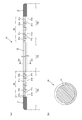
- the guide wire according to the 1st Embodiment of this invention is shown, (a) is a front view, (b) is an enlarged sectional view of line bb.
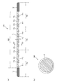
- the guide wire according to the 2nd Embodiment of this invention is shown, (a) is a front view, (b) is an enlarged sectional view of line bb.
- a guide wire according to a third embodiment of the present invention is shown, (a) is a front view, and (b) is an enlarged sectional view taken along line bb.
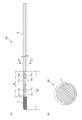
- the guide wire according to the 4th embodiment of the present invention is shown, (a) is a front view, and (b) is a front view of a modified example.
- FIG. 1 shows a guide wire 10 according to the first embodiment.
- FIG. 2 shows the guide wire 10A according to the second embodiment.
- FIG. 3 shows the guide wire 10B according to the third embodiment.
- FIG. 4 shows the guide wire 10C according to the fourth embodiment.
- FIG. 5 shows the guide wire 10D according to the fifth embodiment.
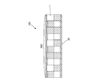
- FIG. 6 shows the guide wire 10E according to the sixth embodiment.
- FIG. 7 shows the guide wire 10F according to the seventh embodiment.
- the guide wire 10 is for medical use, which is inserted into the body and used, and has a core material 11 extending in an elongated linear shape.
- the guide wire 10 is basically configured by covering the outer circumference with a surface film such as urethane resin over the entire length of the core material 11.
- the guide wire 10 has an intermediate portion 10c that occupies most of the longitudinal direction between the distal tip portion 10a, the proximal proximal end portion 10b, and the distal end portion 10a and the proximal end portion 10b in the major axis direction. And consists of.
- the outer diameter of the guide wire 10 is preferably 0.4 to 1.2 mm, for example.
- the outer diameter of the guide wire 10 is substantially the same over the entire length.
- the tip portion 10a may be provided with a taper whose outer diameter gradually decreases toward the tip end portion. Due to such a tapered taper, it can be easily inserted even in a narrow body cavity.
- a taper may be provided in the same manner.
- both the tip portion 10a and the base end portion 10b of the guide wire 10 can be inserted into the body and used.
- the diameters of the tip portion 10a and the base end portion 10b are different, or the materials of the core material 11 and the surface coating are different between the tip portion 10a and the base end portion 10b, and the hardness of each is different. It is good to provide it. This makes it possible to appropriately use the tip end portion 10a and the base end portion 10b according to the type of medical procedure.
- the total length of the guide wire 10 is a design item that is appropriately set according to the medical purpose, for example, in the range of about 1000 to 6000 mm. Further, the length of the tip portion 10a of the total length of the guide wire 10 is preferably in the range of, for example, about 50 to 1500 mm from the tip end. Similarly, the length of the base end portion 10b is preferably in the range of, for example, about 50 to 1500 mm from the rearmost end. Of course, the lengths of the tip portion 10a and the base end portion 10b may be different. A flexible coil may be provided in the tip portion 10a and the base end portion 10b to assist the insertion operation into the body.
- Radiation impermeable may be added to the tip portion 10a and the base end portion 10b.
- the radiation opaque portion 12 is provided on a part of the tip portion 10a on the most advanced side and a part of the proximal end portion 10b on the most proximal end side, respectively.
- the radiation opaque portion 12 is formed by containing, for example, an X-ray contrast medium (for example, barium sulfate) in the surface coatings of the tip portion 10a and the proximal end portion 10b. This makes it possible to easily grasp the positions of the tip end portion 10a and the base end portion 10b under fluoroscopy.
- an X-ray contrast medium for example, barium sulfate
- a wire rod such as tungsten, gold, platinum, or tantalum is spirally wound around the core material 11 to form a coil-shaped marker, or the above-mentioned metal ring-shaped marker is also attached. In some cases, visibility under fluoroscopy may be ensured.
- the core material 11 is made of a metal such as a stainless alloy so as to extend in a linear shape having elasticity and no twist.
- An identification pattern 20 that can be visually recognized over a predetermined length in the long axis direction of the core material 11 is provided on the outer peripheral surface of the core material 11.
- the identification pattern 20 is visible under an endoscope or with the naked eye, and confirms the movement and position of the part where the identification pattern 20 is located in the body.
- the outer peripheral surface of the core material 11 on which the identification pattern 20 is provided corresponds to the outer surface of the surface film coated on the core material 11, but if the outer peripheral surface of the core material 11 is not covered with the surface film, the core It may be a direct outer surface such as a metal forming the material 11.
- the predetermined length of the core material 11 provided with the identification pattern 20 in the major axis direction is the length of the remaining portion of the tip portion 10a excluding the radiation opaque portion 12 and the radiation opaque portion 12 of the base end portion 10b. It is the length of the remaining part excluded. That is, the identification pattern 20 is provided over the length from the base terminal of the radiation opaque portion 12 to the base terminal of the entire tip portion 10a of the tip portion 10a. Further, the identification pattern 20 is provided over a length from, for example, the tip terminal of the radiation opaque portion 12 to the tip terminal of the entire base end portion 10b of the base end portion 10b.
- the identification pattern 20 is formed by a plurality of segments 21 that are independently partitioned and arranged along the long axis direction of the core material 11.
- the segments 21 are configured independently of each other, so that individual colors (colors), materials, thicknesses, and the like can be freely determined.
- the width of the core member 11 in the long axis direction can be arbitrarily set in each of the segments 21 within a range that can be visually recognized under an endoscope or, in some cases, with the naked eye. Further, the thickness of each of the segments 21 in the axial direction of the core material 11 can be arbitrarily set.
- the segment 21 can form a continuous pattern in the long axis direction of the core material 11 as the identification pattern 20. Further, the segment 21 can form continuous unevenness in the long axis direction of the core material 11 as the identification pattern 20.
- the boundary where the segments 21 are adjacent to each other forms a line along a cross section orthogonal to the long axis direction of the core member 11. That is, the segment 21 forms a pattern that is partitioned perpendicular to the long axis direction of the core material 11.
- the segment 21 is different for each region in which the outer peripheral surface of the core material 11 extends in the longitudinal direction divided in the circumferential direction. That is, the outer peripheral surface of the core material 11 is divided into two in the circumferential direction, for example, and two different colored segments 21a and 21b having the same width alternate on one half peripheral surface (upper half in FIG. 1) on one side. On the other half peripheral surface (lower half in FIG. 1) of the other half, the segments 21c and 21d having the same width (about twice) wider than the segments 21a and 21b but different colors are arranged so as to be aligned with each other. Are arranged so as to be arranged alternately.
- the width ratio of the wide segments 21a and 21b may be arbitrarily set in the range of, for example, 1.5 to 5 times that of the narrow segments 21a and 21b.
- Each segment 21a to 21d has a semicircular ring width of each segment.
- segments 21a to 21d are collectively referred to, they are collectively referred to as "segment 21".
- each segment 21 may be appropriately determined, for example, in the range of about 1 to 10 mm so that it can be visually recognized under an endoscope or with the naked eye. Specifically, for example, if the width of the segments 21a and 21b is 5 mm on one half peripheral surface of the core material 11, the width of 21c and 21d on the other half peripheral surface may be 10 mm. This makes it possible to visually distinguish one half peripheral surface from the other half peripheral surface in the circumferential direction of the outer peripheral surface of the core material 11.
- the widths of the segments 21 do not necessarily have to be the same width even if they are adjacent to each other in the long axis direction, but when they are aligned to the same width, the identification pattern 20 is an index of length or It is intended as a major mark.
- each segment 21 it is advisable to appropriately select two or more colors that can be visually recognized under an endoscope or with the naked eye.
- the segments 21 of two colors may be repeatedly arranged in a fixed arrangement or arranged so as to be randomly arranged.
- the color of the segment 21 it is preferable to select a color having a significantly different contrast so that the boundaries can be clearly distinguished from each other.
- each segment 21 is indistinguishable if adjacent objects are the same color, and can be regarded as one segment 21 having a width in which the segments 21 of the same color are lined up. Further, in the identification pattern 20 in which the two color segments 21 are alternately arranged, the color of the core material 11 itself is left as it is for the portion of the segment 21 of the other color other than the segment 21 of one color. It may be formed. Further, if the two-color segments 21 having the same width are alternately arranged on the one half peripheral surface and the other half peripheral surface in the circumferential direction of the outer peripheral surface of the core material 11, a checkerboard pattern can be formed on both of them. ..
- the intermediate portion 10c is also divided into two in the circumferential direction of the outer peripheral surface of the core material 11.
- one half peripheral surface of the intermediate portion 10c has the same color as one segment 21a forming the identification pattern 20
- the other half peripheral surface of the intermediate portion 10c has the same color as the other segment 21b forming the identification pattern 20.
- the segment 21 of the identification pattern 20 and the intermediate portion 10c are colored by, for example, a well-known printing technique. Further, each segment 21 may have an X-ray contrast property.
- the boundary between the tip portion 10a and the intermediate portion 10c of the guide wire 10 can be identified by the end of the identification pattern 20.
- the boundary is the edge of the segment 20 located at the end of the identification pattern 20, it forms a line orthogonal to the long axis direction of the core material 11 as described above.
- the boundary between the tip portion 10a and the intermediate portion 10c and the boundary between the base end portion 10b and the intermediate portion 10c may be provided with markings for clarifying the boundaries.
- the marking here may also be formed by a line orthogonal to the long axis direction of the core material 11.
- the operation of the guide wire 10 according to the first embodiment will be described.
- the endoscope is introduced into the body, for example, orally, and the guide wire 10 is inserted into the body through the endoscope from the tip portion 10a (or the proximal end portion 10b). Will be done.
- the guide wire 10 is operated by rotating, pushing or pulling around an axis according to necessary treatment.
- the hardness and the like of the tip end portion 10a and the base end portion 10b of the guide wire 10 are different, they can be appropriately used according to the type of treatment.
- the tip portion 10a (base end portion 10b) of the guide wire 10 has a radiation opaque portion 12, and the position of the tip portion 10a (base end portion 10b) can be grasped under fluoroscopy.
- the outermost surface of the radiation opaque portion 12 is coated with, for example, a hydrophilic polymer (polyvinylpyrrolidone, maleic anhydride-based polymer, silicone, etc.) and processed as a low-friction surface portion, the tip portion 10a is smoother. (Base end portion 10b) can be inserted into the body and operated.
- the tip portion 10a of the guide wire 10 is provided with an identification pattern 20 in addition to the radiation opaque portion 12. Therefore, when the operator operates the guide wire 10 through the endoscope, the movement and position of the tip portion 10a can be easily confirmed, and the operability of the guide wire is improved.
- radiation opacity is added to the identification pattern 20 in units of segments 21 so that the pattern of the identification pattern 20 can be confirmed under fluoroscopy, the movement and position of the tip portion 10a can be confirmed more accurately. can do.
- the guide wire 10 is inserted so as to reach a specific treatment target in the body cavity, and then guides or positions a catheter or the like for performing various treatments.
- the catheter or the like is positioned by the guide wire 10 and then operated through the endoscope. At this time, the guide wire 10, the catheter, and the region where these are positioned can be visually observed through an endoscope. At this time, it is important to grasp the position of the tip portion 10a (base end portion 10b) by the identification pattern 20.
- the identification pattern 20 is formed by a plurality of segments 21 that are independently partitioned and arranged along the long axis direction of the core material 11. By combining such segments 21, the identification pattern 20 can be continuously formed over a predetermined length, for example, in various ways including the width and color, thickness and shape of each segment 21 forming a regular pattern. It can be in the form.
- the segments 21 of the identification pattern 20 are independent of each other, it is easy to switch the width, color, thickness, material, etc. for each segment 21.
- the segments 21 in FIG. 1 it is possible to easily change only the segment 21a of a specific color to a different color all at once or only a part of the segment 21a.
- the formation of the identification pattern 20 by the segment 21 is realized, for example, by spraying a resin paint with a fine spray, masking, or the like as a well-known printing technique.
- the degree of freedom in designing the identification pattern 20 is increased, and the productivity is also improved.
- the pattern attached to the conventional guide wire in general, it is continuously and integrally formed in advance on the resin film covering the core material, so that only a part of the continuous pattern is locally formed. It was difficult to switch to different colors and materials. Further, if only a part of the continuous pattern is switched, there is a problem that the productivity is significantly impaired.
- the identification pattern 20 of the present embodiment by arranging the segments 21 of two colors alternately, a continuous regular two-color striped pattern is formed in the long axis direction of the core material 11. Since such a striped pattern serves as an index of length as a major mark, it is easy to perform an operation or position such as how much the guide wire 10 is inserted into the body through the identification pattern 20 when moving the guide wire 10 forward or backward. You can check.
- the outer peripheral surface of the core material 11 is divided into two in the circumferential direction, one half peripheral surface (upper half in FIG. 1) and the other half peripheral surface (lower half in FIG. 1). ), And the widths of the segments 21 are different from each other.
- the guide wire 10 is rotated through the identification pattern 20 during the operation of rotating the guide wire 10. The operation can be easily confirmed.
- the outer peripheral surface of the intermediate portion 10c is also divided into two, one half peripheral surface (upper half in FIG. 1) and the other half circumference.
- the surface (lower half in FIG. 1) is painted in different colors.
- the boundary where the segments 21 of the identification pattern 20 are adjacent to each other forms a line along a cross section orthogonal to the long axis direction of the core material 11.
- the boundary of each segment 21 does not shift in the long axis direction of the core material 11 regardless of the angle of the guide wire 10 in the circumferential direction of the identification pattern 20. Therefore, the boundary between the tip portion 10a and the intermediate portion 10c, which is the boundary of the segment 21, can be clearly determined, and the operability of the guide wire 10 is improved.
- the boundary of the portion where the pattern switches is the entire circumference of the guide wire.
- FIG. 2 shows a second embodiment of the present invention.
- the guide wire 10A according to the second embodiment is basically configured in the same manner as in the first embodiment, but the configuration of the identification pattern 20A is different.
- the same types of parts as those in the first embodiment are designated by the same reference numerals, and duplicated description will be omitted.
- the outer peripheral surface of the core material 11 is divided into four in the circumferential direction, and in the drawing, the upper peripheral surface and the upper first peripheral surface (upper side in FIG. 2) , The four regions divided into the lower second peripheral surface (lower side in FIG. 2) and the third peripheral surface and the fourth peripheral surface (both sides in FIG. 2) on both sides are the core material 11, respectively. Extends in the long axis direction of.
- each identification pattern 20A is provided.
- each identification pattern 20A is formed by alternately arranging two color segments 21e and 21f.
- the widths of the segments 21e and 21f are set to be narrower than those of the segments 21a of the first embodiment described above.
- each segment 21 has an arc-shaped cross section having a central angle of 90 degrees.
- the identification pattern 20A at the tip portion 10a is arranged on the first peripheral surface and the second peripheral surface by alternately shifting the colors in the long axis direction of the core material 11.
- the identification pattern 20A at the base end portion 10b segments 21 of three or more colors may be repeatedly arranged in a fixed arrangement or arranged so as to be randomly arranged.
- each segment 21 may be set to a plurality of completely different colors and widths.
- the identification pattern 20A is not provided in the intermediate portion 10c of the guide wire 10A, but the intermediate portion 10c is also divided into four in the circumferential direction of the outer peripheral surface of the core material 11.
- the first peripheral surface of the intermediate portion 10c is colored differently from any color of the segment 21 forming the identification pattern 20A, for example, and the second peripheral surface of the intermediate portion 10c is one that forms the identification pattern 20A. It has the same color as the segment 21e.
- the portions other than the radiation opaque portion 12 of the tip end portion 10a and the base end portion 10b, and the third and fourth peripheral surfaces extending over the intermediate portion 10c have different colors. It is attached.
- the third peripheral surface and the fourth peripheral surface may be formed so as to leave the core material 11 itself as a background color, for example.
- the identification pattern 20A of the guide wire 10A and the intermediate portion 10c that does not include the identification pattern 20A it is possible to design various forms according to, for example, the type of medical procedure and the purpose of use.
- FIG. 3 shows a third embodiment of the present invention.
- the guide wire 10B according to the third embodiment is basically configured in the same manner as the first embodiment, except that the identification pattern 20B is continuously provided in the intermediate portion 10c. ..
- the same types of parts as those in the first embodiment are designated by the same reference numerals, and duplicated description will be omitted.
- the predetermined length of the core material 11 provided with the identification pattern 20B in the major axis direction is the radiation opaque portion of the base end portion 10b from the portion of the tip portion 10a excluding the radiation opaque portion 12. It is the length to reach the part excluding the part 12. That is, the identification pattern 20B extends from the base terminal of the radiation opaque portion 12 of the tip portion 10a to the tip terminal of the radiation opaque portion 12 of the base end portion 10b over substantially the entire length of the core material 11 including the intermediate portion 10c. It is provided.
- the segment 21 itself of the identification pattern 20B is the same as that of the first embodiment.
- the outer peripheral surface of the core material 11 is divided into two in the circumferential direction, one half peripheral surface on one side (upper half in FIG. 1) and the other side. Two regions divided into the other half peripheral surface (lower half in FIG. 1) extend in the major axis direction of the core material 11, respectively. Of these two regions, one half peripheral surface (upper half in FIG. 3) is arranged so that segments 21a and 21b of the same width but different colors are arranged alternately, and the other half peripheral surface (lower in FIG. 3). On the side half), segments 21c and 21d having the same width (about twice) wider than the segments 21a and 21b but different colors are arranged so as to be alternately arranged.
- the position where the identification pattern 20B is provided is not limited to the tip portion 10a and the base end portion 10b of the guide wire 10B, and the identification pattern 20B is also provided in the intermediate portion 10c operated by the operator on the way. You may.
- FIG. 4 shows a fourth embodiment of the present invention.
- the guide wire 10C according to the fourth embodiment is basically configured in the same manner as the first embodiment, but the tip of the tip portion 10a and the base end of the base end portion 10b are respectively bent at a predetermined angle. The difference is that they are.
- the same types of parts as those in the first embodiment are designated by the same reference numerals, and duplicated description will be omitted.
- the tip of the tip 10a of the guide wire 10C is less likely to be caught by the inner wall or the like in the body cavity. At the same time, damage to the inner wall and the like can be prevented.
- the base end of the base end portion 10b is also bent at the same angle in a symmetrical direction on the same plane through which the axis of the core member 11 passes.
- the identification pattern 20 provided on the tip end portion 10a and the base end portion 10b of the guide wire 10C is the same as that of the first embodiment.
- the base end of the base end portion 10b is at the same angle which is not symmetrical but upside down on the same plane through which the axis of the core material 11 passes. You may bend it. Only one of the tip of the tip 10a and the base end of the base 10b may be bent. Further, as another bending process, the tip of the tip portion 10a (base end of the base end portion 10b) may be curved in a J shape, for example.
- the bending direction should be along any one of the regions in which the outer peripheral surface of the core material 11 is divided into the circumferential direction. It is good to match.
- the bending direction of the tip (base end) of the guide wire 10C can be easily confirmed at hand by observing the color and the identification pattern 20 of the region extending in the same direction as the bending direction in the intermediate portion 10c. Become. Therefore, the operability of the guide wire 10C can be further improved. It is not necessary to provide an index for confirming such a bending direction over the entire length of the guide wire 10C, and it is sufficient if it is at least in a range that can be visually recognized by the operator.
- the tip of the guide wire is bent into a J shape, for example.
- a technique in which a display means for indicating the bending direction is provided on a resin film covering a guide wire is also known (for example, JP-A-11-89940). See publication).
- This display means needs to be provided separately regardless of the pattern for confirming the movement and position of the guide wire, which has been a factor of cost increase. Therefore, there has been a demand for a device for reducing the cost by sharing the pattern and the display means, for example.
- the fourth embodiment can solve the problems of the prior art in this way.
- FIG. 5 shows a fifth embodiment of the present invention.
- the guide wire 10D according to the fifth embodiment is basically configured in the same manner as the first embodiment, but the radii of the segments 21 forming the identification pattern 20D centered on the axial center of the core material 11, respectively. The difference is that the thicknesses on the outside of the direction are set to be staggered.
- the same types of parts as those in the first embodiment are designated by the same reference numerals, and duplicated description will be omitted.
- the widths of the segments 21 of the identification pattern 20D are made the same, and the thicknesses of the adjacent segments 21 are staggered to form regular irregularities. ing.
- FIG. 5 schematically shows a part of the guide wire 10D provided with the identification pattern 20D, and the step between the segments 21 is also exaggerated and greatly expressed as compared with the ratio based on the actual size of the actual product. ing.
- the segments 21 that are alternately arranged include thick and large-diameter segments 21g to 21j that are arranged alternately, and thin and small-diameter segments 21k and 21l. Since each of these segments 21g to 21l is also provided independently of each other, it is possible to arbitrarily change the thickness of each segment and freely set the unevenness.
- one segment 21 may be provided so as to have two levels of thickness.
- the color of each segment 21 can be freely set, for example, two colors arranged in the same color can be arranged alternately, or two colors can be arranged alternately one by one.
- the outer peripheral surface of the core material 11 is divided into two in the circumferential direction, one half peripheral surface on one side (upper half in FIG. 5) and the other on the other side. Two regions divided into the other half peripheral surface (lower half in FIG. 5) extend in the major axis direction of the core material 11, respectively.
- FIG. 6 shows a sixth embodiment of the present invention.
- the guide wire 10E according to the sixth embodiment is basically configured in the same manner as in the fifth embodiment, but is made of a transparent material at a position including at least the identification pattern 20D on the outer peripheral surface of the core material 11. The difference is that the covering portion 30 having a smooth surface is provided.
- the same types of parts as those in the fifth embodiment are designated by the same reference numerals, and duplicated description will be omitted.
- the coating portion 30 is a coating formed of, for example, a fluororesin (polytetrafluoroethylene) or a low-friction, transparent resin such as polyethylene or polypropylene. As shown in FIG. 6, the covering portion 30 may be covered for each identification pattern 20D, but may be covered so as to be continuous over the entire length of the guide wire 10E. Further, it is conceivable to cover each segment 21 in the identification pattern 20D. Note that FIG. 6 schematically shows a part of the guide wire 10E.
- the covering portion 30 finishes the outer surface with a smooth surface, thereby causing the step. It is possible to eliminate the inconvenience. Further, since the covering portion 30 is made of a transparent material, the identification pattern 20 can be visually recognized as it is, and the visibility of the design such as the pattern by each segment 21 is not impaired.
- the covering portion 30 by providing the covering portion 30, the frictional resistance at the time of inserting the guide wire 10 can be reduced regardless of the presence or absence of a step between the segments 21. Further, the covering portion 30 makes it possible to protect the identification pattern 20D and prevent damage to the segment 21.
- FIG. 7 shows a seventh embodiment of the present invention.
- the guide wire 10F according to the seventh embodiment is basically configured in the same manner as the first embodiment, except that the base end portion 10b is omitted.
- the same types of parts as those in the first embodiment are designated by the same reference numerals, and duplicated description will be omitted.
- proximal end portion 10b proximal to the guide wire 10 does not necessarily have to be configured in the same manner as the tip end portion 10a, and special configurations such as the radiation opaque portion 12 and the identification pattern 20 may be omitted. .. This also applies to other embodiments.
- the specific configuration is not limited to the above-described embodiments, and the present invention may be changed or added without departing from the gist of the present invention.
- the specific length and diameter of the guide wire 10 and the shapes at both ends are not limited to those shown in the figure.
- the guide wire 10 is not necessarily limited to use in a medical procedure using an endoscope.
- identification patterns 20, 20A, and 20B having the same pattern are provided on the tip portion 10a and the base end portion 10b of the guide wires 10, 10A, and 10B, respectively.
- the identification patterns 20 having different patterns may be provided.
- the segment 21 is made different for each region where the outer peripheral surface of the core material 11 extends in the longitudinal direction divided in the circumferential direction, but the segment 21 extends over the circumferential direction of the outer peripheral surface. They may be formed to be the same. In this case, each segment 21 is formed in an annular shape over the entire circumference of the core member 11 around the axis.
- the guide wire according to the present invention can be applied to a guide wire used for various medical procedures.
Landscapes
- Health & Medical Sciences (AREA)
- Life Sciences & Earth Sciences (AREA)
- Biophysics (AREA)
- Pulmonology (AREA)
- Engineering & Computer Science (AREA)
- Anesthesiology (AREA)
- Biomedical Technology (AREA)
- Heart & Thoracic Surgery (AREA)
- Hematology (AREA)
- Animal Behavior & Ethology (AREA)
- General Health & Medical Sciences (AREA)
- Public Health (AREA)
- Veterinary Medicine (AREA)
- Media Introduction/Drainage Providing Device (AREA)
Priority Applications (1)
| Application Number | Priority Date | Filing Date | Title |
|---|---|---|---|
| CN202080022376.6A CN113597323B (zh) | 2019-03-29 | 2020-03-10 | 导丝 |
Applications Claiming Priority (2)
| Application Number | Priority Date | Filing Date | Title |
|---|---|---|---|
| JP2019067667A JP6968846B2 (ja) | 2019-03-29 | 2019-03-29 | ガイドワイヤー |
| JP2019-067667 | 2019-03-29 |
Publications (1)
| Publication Number | Publication Date |
|---|---|
| WO2020203083A1 true WO2020203083A1 (ja) | 2020-10-08 |
Family
ID=72668566
Family Applications (1)
| Application Number | Title | Priority Date | Filing Date |
|---|---|---|---|
| PCT/JP2020/010218 Ceased WO2020203083A1 (ja) | 2019-03-29 | 2020-03-10 | ガイドワイヤー |
Country Status (3)
| Country | Link |
|---|---|
| JP (1) | JP6968846B2 (https=) |
| CN (1) | CN113597323B (https=) |
| WO (1) | WO2020203083A1 (https=) |
Cited By (1)
| Publication number | Priority date | Publication date | Assignee | Title |
|---|---|---|---|---|
| US20240277502A1 (en) * | 2023-02-17 | 2024-08-22 | Merit Medical Systems, Inc. | Fenestrated vascular aortic repair stent deployment devices, systems, and methods |
Families Citing this family (1)
| Publication number | Priority date | Publication date | Assignee | Title |
|---|---|---|---|---|
| JP7733630B2 (ja) * | 2022-10-20 | 2025-09-03 | クリエートメディック株式会社 | ガイドワイヤー |
Citations (4)
| Publication number | Priority date | Publication date | Assignee | Title |
|---|---|---|---|---|
| JPH0994298A (ja) * | 1995-09-28 | 1997-04-08 | Terumo Corp | ガイドワイヤー |
| JP2003093516A (ja) * | 2001-09-26 | 2003-04-02 | Olympus Optical Co Ltd | ガイドワイヤー |
| US20080228109A1 (en) * | 2007-03-14 | 2008-09-18 | Terumo Kabushiki Kaisha | Guide wire |
| JP2015065986A (ja) * | 2013-09-26 | 2015-04-13 | テルモ株式会社 | 医療デバイスおよび医療デバイスの製造方法 |
Family Cites Families (4)
| Publication number | Priority date | Publication date | Assignee | Title |
|---|---|---|---|---|
| JPH11137693A (ja) * | 1997-11-13 | 1999-05-25 | Unitika Ltd | 医療用ガイドワイヤー |
| US6605049B1 (en) * | 2000-12-21 | 2003-08-12 | Advanced Cardiovascular Systems, Inc. | Marking system and method for medical devices |
| EP3093038B1 (en) * | 2007-04-18 | 2019-05-22 | Access Scientific, Inc. | Access device |
| CN102106715B (zh) * | 2010-11-09 | 2012-11-28 | 麻树人 | 内窥镜导丝 |
-
2019
- 2019-03-29 JP JP2019067667A patent/JP6968846B2/ja active Active
-
2020
- 2020-03-10 WO PCT/JP2020/010218 patent/WO2020203083A1/ja not_active Ceased
- 2020-03-10 CN CN202080022376.6A patent/CN113597323B/zh active Active
Patent Citations (4)
| Publication number | Priority date | Publication date | Assignee | Title |
|---|---|---|---|---|
| JPH0994298A (ja) * | 1995-09-28 | 1997-04-08 | Terumo Corp | ガイドワイヤー |
| JP2003093516A (ja) * | 2001-09-26 | 2003-04-02 | Olympus Optical Co Ltd | ガイドワイヤー |
| US20080228109A1 (en) * | 2007-03-14 | 2008-09-18 | Terumo Kabushiki Kaisha | Guide wire |
| JP2015065986A (ja) * | 2013-09-26 | 2015-04-13 | テルモ株式会社 | 医療デバイスおよび医療デバイスの製造方法 |
Cited By (2)
| Publication number | Priority date | Publication date | Assignee | Title |
|---|---|---|---|---|
| US20240277502A1 (en) * | 2023-02-17 | 2024-08-22 | Merit Medical Systems, Inc. | Fenestrated vascular aortic repair stent deployment devices, systems, and methods |
| WO2024173814A1 (en) * | 2023-02-17 | 2024-08-22 | Merit Medical Systems, Inc. | Fenestrated vascular aortic repair stent deployment devices, systems, and methods |
Also Published As
| Publication number | Publication date |
|---|---|
| CN113597323B (zh) | 2022-12-13 |
| JP2020162953A (ja) | 2020-10-08 |
| JP6968846B2 (ja) | 2021-11-17 |
| CN113597323A (zh) | 2021-11-02 |
Similar Documents
| Publication | Publication Date | Title |
|---|---|---|
| US6636758B2 (en) | Marker wire and process for using it | |
| JP5393684B2 (ja) | 医療用具 | |
| ES2379911T3 (es) | Alambre de guía | |
| US7195612B2 (en) | Esophageal balloon catheter with visual marker | |
| EP3546008B1 (en) | Catheter and method for manufacturing catheter | |
| US20160361520A1 (en) | Guide wire for medical devices | |
| JP6968846B2 (ja) | ガイドワイヤー | |
| JP5536459B2 (ja) | ガイドワイヤ | |
| EP3116582B1 (en) | Kink-resistant guidewire with improved rigidity | |
| US20210186559A1 (en) | Dilator | |
| US20070118053A1 (en) | Identifiable wire guide | |
| US20080228138A1 (en) | Catheter with balloon having visual marker | |
| US20230200845A1 (en) | Guidewire having guidewire markers | |
| US8303519B2 (en) | Guide wire having markings to indicate changes in structural features | |
| JP6793303B2 (ja) | 医療用ガイドワイヤ | |
| JP2011110392A (ja) | 内視鏡用ガイドワイヤー | |
| JP2018191883A (ja) | 医療用長尺体 | |
| JP2015065979A (ja) | ガイドワイヤ | |
| JP5806441B2 (ja) | ガイドワイヤ | |
| JP7733630B2 (ja) | ガイドワイヤー | |
| CN115003362A (zh) | 导丝 | |
| JP4402814B2 (ja) | 医療用ガイドワイヤ | |
| JP2020162953A5 (https=) | ||
| JPH11137693A (ja) | 医療用ガイドワイヤー | |
| JP1767208S (ja) | ガイドワイヤ |
Legal Events
| Date | Code | Title | Description |
|---|---|---|---|
| 121 | Ep: the epo has been informed by wipo that ep was designated in this application |
Ref document number: 20782544 Country of ref document: EP Kind code of ref document: A1 |
|
| NENP | Non-entry into the national phase |
Ref country code: DE |
|
| 122 | Ep: pct application non-entry in european phase |
Ref document number: 20782544 Country of ref document: EP Kind code of ref document: A1 |