WO2020202964A1 - 信号処理システム - Google Patents
信号処理システム Download PDFInfo
- Publication number
- WO2020202964A1 WO2020202964A1 PCT/JP2020/008530 JP2020008530W WO2020202964A1 WO 2020202964 A1 WO2020202964 A1 WO 2020202964A1 JP 2020008530 W JP2020008530 W JP 2020008530W WO 2020202964 A1 WO2020202964 A1 WO 2020202964A1
- Authority
- WO
- WIPO (PCT)
- Prior art keywords
- signal
- optical
- unit
- electric signal
- radio wave
- Prior art date
- Legal status (The legal status is an assumption and is not a legal conclusion. Google has not performed a legal analysis and makes no representation as to the accuracy of the status listed.)
- Ceased
Links
Images

Classifications
-
- H—ELECTRICITY
- H04—ELECTRIC COMMUNICATION TECHNIQUE
- H04B—TRANSMISSION
- H04B10/00—Transmission systems employing electromagnetic waves other than radio-waves, e.g. infrared, visible or ultraviolet light, or employing corpuscular radiation, e.g. quantum communication
- H04B10/70—Photonic quantum communication
-
- H—ELECTRICITY
- H04—ELECTRIC COMMUNICATION TECHNIQUE
- H04B—TRANSMISSION
- H04B10/00—Transmission systems employing electromagnetic waves other than radio-waves, e.g. infrared, visible or ultraviolet light, or employing corpuscular radiation, e.g. quantum communication
- H04B10/25—Arrangements specific to fibre transmission
- H04B10/2575—Radio-over-fibre, e.g. radio frequency signal modulated onto an optical carrier
-
- H—ELECTRICITY
- H04—ELECTRIC COMMUNICATION TECHNIQUE
- H04K—SECRET COMMUNICATION; JAMMING OF COMMUNICATION
- H04K1/00—Secret communication
- H04K1/02—Secret communication by adding a second signal to make the desired signal unintelligible
Definitions
- the present invention relates to a signal processing system.
- the network systems that make up the Internet are described by the OSI reference model developed by the International Organization for Standardization.
- OSI reference model developed by the International Organization for Standardization.
- the physical layer of layer 1 and the application layer of layer 7 are separated, and the interface connecting each layer is standardized or standardized by de facto.
- the lowest layer is the physical layer, which plays the role of actually transmitting and receiving signals by wire or wireless.
- security (often relying on mathematical cryptography) is implemented at layer 2 or higher, and no security measures are taken at the physical layer. However, there is a risk of eavesdropping even in the physical layer.
- optical fiber communication which is a typical example of wired communication
- Patent Document 1 it is possible to take measures against eavesdropping in the physical layer using an optical fiber by transmitting multi-valued information as an optical signal, but the physical layer in wireless communication. It was not possible to take measures against eavesdropping in.
- An object of the present invention is to take measures against eavesdropping at the physical layer in wireless communication.
- the signal processing system of one aspect of the present invention is An optical generating means that generates multi-valued information that takes a multi-valued state based on predetermined data as an optical signal, and Photoelectric conversion means for converting the optical signal into an electric signal, A radio wave transmitting means for transmitting the multi-valued information converted into the electric signal as a radio wave, and To be equipped.
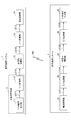
- FIG. 1 is a block diagram showing an example of a configuration of a signal transmission / reception system according to an embodiment of the signal processing system of the present invention.
- the signal transmission / reception system of the example of FIG. 1 is configured to include a signal transmission system 1 and a signal reception system 2.
- the signal transmission system 1 encrypts the signal to be transmitted based on the Y-00 optical communication quantum cryptography protocol and transmits it in the form of radio wave RW.
- the signal receiving system 2 receives the radio wave RW, decodes it based on the protocol of Y-00 optical communication quantum cryptography, and receives the signal of the above-mentioned form.
- the Y-00 optical communication quantum cryptography is based on the Y-00 optical communication quantum cryptography protocol, and after converting predetermined data to be transmitted into multi-valued information, it is transmitted as an optical signal.
- This is an encryption method based on the principle that the received signal becomes an encrypted encrypted signal.
- the signal transmission system 1 is configured to include an optical signal generation unit 11, an optical signal amplification unit 12, an O / E conversion unit 13, and a radio wave transmission unit 14.
- the optical signal generation unit 11 generates multi-valued information in a multi-valued state based on predetermined data as an optical signal.
- This optical signal is a signal to be transmitted, the details of which will be described later.
- the optical signal generation unit 11 includes a Y-00 encryption output unit 111 and an E / O conversion unit 112.
- the Y-00 encryption output unit 111 is an electric signal of multi-valued information that takes a multi-valued state based on predetermined data (hereinafter, "first electric signal” in order to clearly distinguish it from the second to fourth electric signals described later. Is called). That is, the Y-00 encryption output unit 111 generates predetermined data to be transmitted or acquires it from a generator (not shown). Using this predetermined data, the Y-00 encryption output unit 111 uses the multi-valued information generated based on the Y-00 optical communication quantum cryptography protocol to provide the signal path LE11 in the form of a first electric signal as the multi-valued information. Output via.
- predetermined data hereinafter, "first electric signal” in order to clearly distinguish it from the second to fourth electric signals described later. Is called. That is, the Y-00 encryption output unit 111 generates predetermined data to be transmitted or acquires it from a generator (not shown). Using this predetermined data, the Y-00 encryption output unit 111 uses the multi-value
- the first electric signal in the signal path LE11 may be either an analog signal or a digital signal, but in the description of the present embodiment, it will be described as an analog signal.
- the signal path LE11 has a configuration capable of transmitting a plurality of bits (for example, from a plurality of signal paths for transmitting signals in parallel or a data processing unit for transmitting signals serially). The configuration) is appropriately provided.
- the E / O conversion unit 112 converts the first electric signal of the multi-valued information output from the Y-00 encryption output unit 111 into an optical signal. That is, the E / O conversion unit 112 converts the first electric signal of the multi-value information input via the LE 11 into an optical signal modulated by an arbitrary modulation method and outputs it via the signal path LO1A.
- the signal path LO1A may be composed of an optical signal path using an optical communication cable.
- the optical communication cable By using the optical communication cable as the signal path LO1A in this way, in the signal transmission system 1, the E / O conversion unit 112 and the O / E conversion unit 13 described later can be installed at a distance.
- the optical signal amplification unit 12 amplifies the optical signal generated from the E / O conversion unit 112. That is, the optical signal amplification unit 12 amplifies and outputs an optical signal generated from the E / O conversion unit and transmitted by the signal path LO1A.
- the optical signal (amplified optical signal) output from the optical signal amplification unit 12 is transmitted to the O / E conversion unit 13 via the signal path LO1B.
- the signal path LO1B may be composed of an optical signal path by an optical communication cable, similarly to the signal path LO1A. That is, the optical signal amplification unit 12 can be used as a repeater in the optical signal path capable of amplifying the attenuated optical signal by passing through the signal path LO1A.
- the optical signal amplification unit 12 can be used as such a repeater, the distance of the optical signal path between the E / O conversion unit 112 and the O / E conversion unit 13 described later can be extended. In other words, the E / O conversion unit 112 and the O / E conversion unit 13 described later can be installed at a further distance from each other.
- the O / E conversion unit 13 clearly defines the optical signal amplified by the optical signal amplification unit 12 and transmitted by the signal path LOB as an electric signal (the first electric signal described above and the third and fourth electric signals described later). In order to distinguish between the above, it is converted into a "second electric signal"). That is, the O / E conversion unit 13 transfers the optical signal corresponding to the multi-valued information generated based on the Y-00 optical communication quantum cryptography protocol to the optical signal transmitted by the signal path LO1. Converts to an electric signal and outputs it. The second electric signal output from the O / E conversion unit 13 is transmitted to the radio wave transmission unit 14 via the signal path LE12.
- the second electric signal is converted from the optical signal by the O / E conversion unit 13, and as a result, becomes an electric signal including shot noise. That is, the signal is encrypted (hereinafter referred to as "encrypted signal") according to the principle of Y-00 optical communication quantum cryptography described later.
- the encrypted signal cannot correctly reconstruct the data unless it is decrypted in the Y-00 optical communication quantum cryptography protocol. That is, even if the second electric signal is intercepted by a third party, it is difficult for the third party to decipher it.
- the term of the encrypted signal refers to an encrypted signal regardless of the form of an electric signal, an optical signal, a radio wave, or the like.
- the optical signal amplification unit 12 is shown by a broken line. This is because the optical signal amplification unit 12 is not an indispensable component for the signal transmission system 1, and even if the optical signal amplification unit 12 is included in the component, the number is not limited to one and is arbitrary. It means that the number is sufficient. That is, when the distance of the optical transmission line between the E / O conversion unit 112 and the O / E conversion unit 13 becomes long, the number of optical signal amplification units 12 serving as relay units in the optical transmission line is increased. Can be introduced individually.
- the signal transmission system 1 may be configured not to include the optical signal amplification unit 12.
- the signal transmission system 1 is configured not to include the optical signal amplification unit 12, and the E / O conversion unit 112 and the O / E conversion unit 13 are directly connected to each other in a signal path. It is assumed that they are connected via LO1A and signal path LO1B (hereinafter, these are collectively referred to as "signal path LO1").
- the radio wave transmission unit 14 transmits the encrypted signal converted into the second electric signal by the O / E conversion unit 13 and transmitted by the signal path LE 12 in the form of radio wave RW. That is, the radio wave transmission unit 14 transmits the second electric signal, which is an encrypted signal, as a radio wave RW via a component such as an antenna after performing control such as predetermined amplification and frequency conversion. That is, the second electric signal transmitted in the form of radio wave RW is an encrypted signal.
- the electric signal of the radio wave RW acquired by a third party converts the multi-valued information generated based on the Y-00 optical communication quantum cryptography protocol into an optical signal, and further converts the optical signal into a second electric signal. It is an encrypted signal converted into a signal. That is, it is difficult to decipher the electric signal of the radio wave RW acquired by a third party.
- the configuration example of the signal transmission system 1 that transmits the encrypted signal encrypted based on the Y-00 optical communication quantum cryptography protocol in the form of the radio wave RW has been described above.
- a configuration example of the signal receiving system 2 that receives the radio wave RW and decodes it based on the Y-00 optical communication quantum cryptography protocol will be described.
- the signal receiving system 2 is configured to include a radio wave receiving unit 21, an E / O conversion unit 22, an optical signal amplification unit 23, an O / E conversion unit 24, and a Y-00 encryption input unit 25. There is.
- the radio wave receiving unit 21 receives the radio wave RW transmitted by the signal transmission system 1. That is, the radio wave receiving unit 21 receives the encrypted signal in the form of radio wave RW with an antenna or the like, and in order to clearly distinguish it from the electric signals (the first and second electric signals described above and the fourth electric signal described later), the following, It is output in the form of "third electric signal”).
- the third electric signal output from the radio wave receiving unit 21 is transmitted to the E / O conversion unit 22 via the signal path LE 21.
- the E / O conversion unit 22 converts the third electric signal corresponding to the radio wave RW received by the radio wave receiving unit 21 into an optical signal. That is, the E / O conversion unit 22 converts the encrypted signal in the form of the third electric signal received by the radio wave receiving unit 21 and transmitted by the signal path LE 21 into the form of an optical signal and outputs it.
- the third electric signal output from the E / O conversion unit 22 is transmitted to the optical signal amplification unit 23 via the signal path LO2A.
- the signal path LO2A may be composed of an optical signal path using an optical communication cable.
- the optical communication cable By using the optical communication cable as the signal path LO2A in this way, in the signal receiving system 2, the E / O conversion unit 22 and the O / E conversion unit 24 described later can be installed at a distance.
- the optical signal amplification unit 23 amplifies the optical signal converted by the E / O conversion unit 22. That is, the optical signal amplification unit 23 amplifies and outputs an optical signal that has been converted by the E / O conversion unit and transmitted by the signal path LO2A.
- the optical signal (amplified optical signal) output from the optical signal amplification unit 23 is transmitted to the O / E conversion unit 24 via the signal path LO2B.
- the signal path LO2B may be composed of an optical signal path by an optical communication cable, similarly to the signal path LO2A. That is, the optical signal amplification unit 23 can be used as a repeater in the optical signal path capable of amplifying the attenuated optical signal by passing through the signal path LO2A.
- the optical signal amplification unit 23 which is such a repeater, the distance of the optical signal path between the E / O conversion unit 22 and the O / E conversion unit 24 described later can be extended. In other words, the E / O conversion unit 22 and the O / E conversion unit 24, which will be described later, can be installed at a further distance from each other.
- the optical signal amplification unit 23 is shown by a broken line. This is because the optical signal amplification unit 23 is not an indispensable component for the signal receiving system 2, and even if the optical signal amplification unit 23 is included in the components, the number is not limited to one and is arbitrary. It means that the number is sufficient. That is, when the distance of the optical transmission line between the E / O conversion unit 22 and the O / E conversion unit 24 becomes long, there are a plurality of optical signal amplification units 23 as relay units in the optical transmission line. Can be introduced individually. On the other hand, when the distance of the optical transmission line between the E / O conversion unit 22 and the O / E conversion unit 24 is shortened, the optical signal generated from the E / O conversion unit 22 is used.
- the signal receiving system 2 can be configured not to include the optical signal amplification unit 23.
- the signal receiving system 2 is configured not to include the optical signal amplification unit 23, and the E / O conversion unit 22 and the O / E conversion unit 24 are directly connected to each other in a signal path. It is assumed that they are connected via LO2A and signal path LO2B (hereinafter, these are collectively referred to as "signal path LO2").
- the O / E conversion unit 24 describes the optical signal amplified by the optical signal amplification unit 12 and transmitted by the signal path LO2 as an electric signal (hereinafter, in order to clearly distinguish it from the first to third electric signals described above). It is converted into a "fourth electric signal"). That is, the O / E conversion unit 24 converts an optical signal corresponding to the encrypted signal of the radio wave RW and transmitted by the optical transmission line including the signal path LO2 into a fourth electric signal and outputs the signal. To do.
- the fourth electric signal output from the O / E conversion unit 24 is transmitted to the Y-00 encryption input unit 25 via the signal path LE 22.
- the Y-00 encryption input unit 25 inputs an encryption signal in the form of a fourth electric signal converted by the O / E conversion unit 24 via the signal path LE22, and is based on the Y-00 optical communication quantum cryptography protocol. By decoding, it is converted into predetermined data that was the transmission target. Further, the Y-00 encryption input unit 25 acquires the decrypted predetermined data or provides it to a reception destination (not shown).
- the radio wave receiving unit 21 and the Y-00 encryption input unit 25 are installed close to each other, the radio wave receiving unit 21 and the Y-00 encryption input unit 25 are directly connected to the signal path LE21 and the signal path LE21. It may be connected via the signal path LE22. That is, the third electric signal can be directly adopted as the fourth electric signal and input to the Y-00 encryption input unit 25.
- optical fiber communication which is a typical wired communication, is adopted as the communication method of the optical signal.
- a third party introduces a branch into the optical fiber and extracts a part of the signal power to obtain a large amount of information (encrypted signal here, hereinafter referred to as "encrypted signal"). In principle, it is possible to steal all at once.
- the Y-00 optical communication quantum cryptography is a quantum cryptography associated with the particle nature of light, and can be applied to optical fiber communication. On the other hand, it could not be applied to communication having extremely small quantum property compared to light, such as wireless communication using radio wave RW.
- the signal transmission system 1 and the signal reception system 2 transmit / receive information (encrypted signal) by wireless communication. Therefore, in the example of FIG. 1, the encrypted signal is transmitted and received by the signal transmission system 1 and the signal reception system 2 in the form of a radio wave RW for wireless communication.
- the signal transmission / reception system of the present embodiment is configured to be able to solve such a problem.
- a method for solving such a problem will be described.
- the Y-00 optical communication quantum cryptography is characterized in that "the ciphertext cannot be obtained correctly due to the effect of quantum noise", and was developed by the applicant.
- the data (plaintext) to be transmitted is represented by one or more aggregates of bit data of "0" or "1".
- Each bit data constituting the transmission data is modulated to a predetermined value among M values (M is an integer value of 2 or more) by a predetermined algorithm. Therefore, hereinafter, this numerical value M is referred to as "modulation number M".
- Y-00 optical communication quantum encryption at least one of the phase and amplitude of the optical signal (carrier wave) is modulated bit by bit by the encryption key on the encryption side and the decryption side to one of the values of the modulation number M. Encrypts the transmitted data (plain text).
- the modulation number M is set to an extremely large value, the feature that "the ciphertext cannot be correctly acquired due to the effect of quantum noise" is realized.
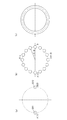
- Japanese Patent Application Laid-Open No. 2012-085028 may be referred to. Therefore, here, the outline of the principle of Y-00 optical communication quantum cryptography will be briefly described with reference to FIGS. 2 and 3 by taking phase modulation as an example.
- FIG. 2 is a diagram illustrating an outline of the principle of Y-00 optical communication quantum cryptography.
- an IQ plane representing the phase and amplitude (intensity) of an optical signal is drawn with the intersection of the vertical axis and the horizontal axis as the origin.
- the phase and amplitude of the optical signal are uniquely determined.
- the phase is an angle formed by a line segment whose starting point is the origin of the IQ plane and whose ending point is a point representing the optical signal, and a line segment representing phase 0.
- the amplitude is the distance between the point representing the Shinko number and the origin of the IQ plane.
- FIG. 2A is a diagram illustrating the principle of ordinary binary modulation in order to facilitate the understanding of Y-00 optical communication quantum cryptography.
- the plaintext transmission data
- the optical signal carrier wave
- the binary values shown in FIG. 2A are obtained for each of the bit data (1 or 0) constituting the plaintext. Modulation shall be performed.
- the bit data is "0”
- the arrangement of the points indicating the optical signal after phase modulation (hereinafter referred to as "symbol points") is 0 (0) on the right side on the horizontal axis. ), That is, the phase is 0.
- the arrangement of the symbol points after phase modulation is the arrangement of the symbol points S12 with ⁇ (1) on the left side on the horizontal axis, that is, the arrangement of the phase of ⁇ .
- the solid circle surrounding the symbol point S11 shows an example of the fluctuation range of the quantum noise when the optical signal of the symbol point S11 is received.
- an example of the fluctuation range of the quantum noise is shown as a solid circle surrounding the symbol point S12.
- one of eight random values is generated by using the encryption key for each bit data constituting the plaintext.
- the phase of the normal binary modulation symbol point (point of phase 0 corresponding to 0 or point of phase ⁇ corresponding to 1) shown in FIG. 2A was randomly generated out of 8 values.
- shot noise Quantum noise
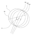
- the position of the original symbol point becomes difficult to determine from the phase information measured on the receiving side. That is, for example, it is assumed that the phase measured on the receiving side at a certain time corresponds to the position of the symbol point S22 shown in FIG. In this case, is it transmitted as an optical signal of the symbol point S22, or what is actually transmitted as an optical signal of the symbol point S21 or the symbol point S23 is measured as the symbol point S22 due to the influence of shot noise. It is indistinguishable whether it was done.
- phase modulation is used in the examples of FIGS. 2 and 3
- amplitude (intensity) modulation may be used instead of or in combination with this. That is, for the modulation of the optical signal using the Y-00 protocol, any modulation method such as intensity modulation, amplitude modulation, phase modulation, frequency modulation, and orthogonal amplitude modulation can be adopted.
- the Y-00 optical communication quantum cryptography makes it possible to make the distance D between the two symbol points sufficiently smaller than the shot noise range SN in any modulation method, and "quantum noise It can have the feature that the ciphertext cannot be obtained correctly due to the effect.
- quantum noise guarantees safety, but in reality, eavesdroppers obtain the correct ciphertext by the effect of all "noise” including classical noise such as thermal noise in addition to quantum noise. Will prevent you from doing so.
- the noise masking amount ⁇ is defined and described as the noise masking amount ⁇ .
- the concept of the noise masking amount ⁇ is a concept that can be applied to other than the distribution of shot noise. A method of applying the concept of noise masking amount ⁇ to other noise will be described later.
- the noise masking amount ⁇ of this example adopts the distance (radius) corresponding to the shot noise range SN described above in FIG. 2 and the standard deviation of the Gaussian distribution of shot noise.
- the noise masking amount ⁇ is the number of other symbol points included in the shot noise range SN. That is, the noise masking amount ⁇ indicates the number of other symbol points whose distance D is smaller than the shot noise range SN with respect to a certain symbol point. That is, the noise masking amount ⁇ is an amount proportional to the encryption strength of the encrypted signal.
- the noise masking amount ⁇ is represented by the following equation (1). ... (1)
- the modulation number M is the number of phase candidates to be modulated for encryption.
- the symbol rate R is a number indicating how many symbol points are sent per unit time.
- Planck's constant h is a physical constant and is a proportional constant related to the energy and frequency of a photon.
- the frequency ⁇ 0 is the frequency of the signal.
- the power P0 is a number representing the power of the signal.
- the noise masking amount ⁇ is a sufficiently large value, masking by shot noise works. That is, the Y-00 photon cryptography works effectively as a cipher. Specifically, for example, when this value is 1 or more, the effect of masking by shot noise is exhibited, and when it is a sufficiently large value, even higher safety is achieved.
- the noise masking amount ⁇ is proportional to the square root of the signal frequency ⁇ 0. In other words, when the frequency ⁇ 0 of the carrier wave is low, the noise masking amount ⁇ becomes small, and the security of encryption becomes low.
- the frequency ⁇ 0 used in optical fiber transmission is 200 [THz] (wavelength is approximately 1.55 [um]).
- the frequency ⁇ 0 used in long-wave wireless communication is 100 [kHz].
- the frequency ⁇ 0 used in wireless communication by microwave has 10 [GHz].
- an example of comparing the noise masking amount ⁇ under the condition that the frequency other than the frequency ⁇ 0 does not change is as follows.
- the condition that the frequency other than the frequency ⁇ 0 does not change is the condition that the symbol rate R and the power P0 are the same.
- the ratio of the noise masking amount ⁇ of wireless communication by the long wave divided by the noise masking amount ⁇ of optical fiber transmission is about 1 / 45,000.
- the ratio of the noise masking amount ⁇ of wireless communication by microwaves divided by the noise masking amount ⁇ of optical fiber transmission is about 1/140.
- the signal transmission / reception system of the present embodiment can also encrypt the radio wave RW in wireless communication in the physical layer. That is, the signal transmission system 1 of the above-described embodiment is a system (a system configured based on such a mechanism) capable of applying the Y-00 optical communication quantum cryptography to wireless communication.
- the signal form of the predetermined data to be transmitted is converted by undergoing various conversions.
- the encrypted signal of FIG. 1 is transmitted in the form of radio wave RW.
- a mechanism for transmitting an encrypted signal including a timing at which predetermined data becomes an encrypted signal by Y-00 optical communication quantum cryptography will be described.
- the optical signal generation unit 11 generates multi-value information that takes a multi-value state based on predetermined data as an optical signal. Further, even if the generated optical signal is intercepted by a third party, the ciphertext cannot be correctly acquired due to the effect of shot noise. Specifically, for example, a third party who intercepts the optical signal of the signal path LO1 acquires the optical signal as an electric signal by O / E conversion. At the timing of O / E conversion, shot noise is generated due to the particle nature of light. As a result, a third party who does not have the Y-00 optical communication quantum cryptography algorithm and its encryption key cannot decrypt the electric signal and correctly obtain the ciphertext.
- the signal transmission system 1 of the example of FIG. 1 converts an optical signal into a second electric signal by the O / E conversion unit 13. That is, similarly to the O / E conversion by a third party described above, at the timing of the O / E conversion in the O / E conversion unit 13, the second electric signal becomes an electric signal in which shot noise is generated. Further, the signal transmission system 1 transmits a second electric signal from the radio wave transmission unit 14. As a result, the radio wave RW is encrypted including shot noise based on the frequency of the optical signal. That is, since shot noise is generated based on the frequency of the optical signal instead of the frequency of the radio wave RW, the electric signal has a large noise masking amount ⁇ .
- the mechanism by which the Y-00 optical communication quantum cryptography can be applied to wireless communication has been described.
- the transmission target The predetermined data is encrypted and becomes an encrypted signal.
- the signal path LO1 can be configured by a long-distance optical fiber or the like. That is, for example, in the case of a long-distance optical fiber, even when a third party works on the optical fiber to intercept the optical signal, the optical signal is encrypted, thus ensuring safety. can do.
- the optical signal generation unit 11 and the E / O conversion unit 13 can be provided at separate positions.
- the optical signal amplification unit 12 when the optical signal amplification unit 12 amplifies the optical signal, noise is added to the optical signal after output. As a result, by adding noise in addition to the shot noise described above, the optical signal is encrypted with a larger noise even when a third party acquires the signal in the signal path LO1A or later. Therefore, it is difficult to decipher.
- the first electric signal is converted into an optical signal by direct modulation of the laser or E / O conversion performed by a combination of the laser and various modulation elements.
- the E / O conversion unit 112 includes a laser light source (not shown).
- the laser light source of the E / O converter 112 generates a monochromatic (unmodulated) carrier wave of frequency fsig.
- the E / O conversion unit 112 converts the first electric signal into an optical signal.
- the radio wave transmission unit 14 can obtain an electric signal having a frequency of the radio wave RW used in wireless communication.
- a radio wave relay device (not shown) may be configured to relay the radio wave RW as a radio wave having a different center frequency.
- the signal transmission / reception system is configured to include the signal transmission system 1 and the signal reception system 2, but the signal transmission system 1 is provided with a function related to signal reception. It may be a signal processing system capable of transmitting and receiving. In this case, in a transmission / reception system including two or more signal processing systems, communication can be performed by an encrypted signal in the form of radio wave RW regardless of the direction of communication.
- the encryption signal may be used in only one direction.
- the configuration in the signal processing system and the configuration of transmission and reception do not necessarily have to be symmetrical.
- the signal when the signal receiving system is an antenna relay station, the signal may be transmitted by the antenna (radio wave transmitting unit) again after receiving the signal by the antenna (radio wave receiving unit) and performing an operation such as amplification.
- the signal receiving system 2 when the signal receiving system 2 is a terminal such as a PC, it is assumed that there is no E / O conversion or O / E conversion, and only electrical processing is performed. That is, the third electric signal received by the radio wave receiving unit 21 may be input to the Y-00 encryption input unit 25. At that time, the third electric signal may be appropriately converted to a center frequency suitable for the Y-00 encryption input unit 25.
- RW radio wave
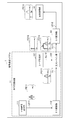
- FIG. 4 is a block diagram showing a detailed configuration example of the signal transmission system of FIG. 1 in which the baseband heterodyne method is adopted.
- the signal transmission system 1 of the example of FIG. 4 further includes a laser generation unit 121, an optical combine unit 122, and signal paths LL11 to LL13 connecting each of the signal transmission system 1 of the example of FIG.
- the Y-00 encryption output unit 111 is a multi-valued device for modulating at least one of the optical phase and the optical amplitude from the predetermined data to be transmitted and the private key based on the Y-00 optical communication quantum encryption protocol.
- the frequencies included in the first electric signal have, for example, the distribution shown in the graph FE11.
- the distribution shown in the graph FE11 conceptually shows the frequencies included in the signal.
- the distribution shown in the graph FE11 has a frequency f on the horizontal axis.
- the arrows, hemispherical shapes, and the like in the distributions shown in the graphs have the same meanings as those in the graph FE11 described above.
- the first electric signal is a signal containing information for modulating at least one of the phase of light and the amplitude of light.
- the optical signal of the example of FIG. 4 is transmitted to the optical combine unit 122 via the signal path LL11 configured by an optical fiber or the like.
- the E / O conversion unit 112 has a configuration in which a laser generation unit (not shown) is combined with a phase modulator, a Machzenda modulator, an IQ modulator, or the like to modulate the phase and amplitude of light or one of them.
- the E / O conversion unit 112 may include a modulation laser generation unit (not shown) and may be configured to directly output the modulated optical signal.
- the frequencies included in the optical signal output from the E / O conversion unit 112 have, for example, the distribution shown in the graph FO11.
- the carrier light of the example of FIG. 4 is transmitted to the optical combine unit 122 via the signal path LL12 composed of an optical fiber or the like.
- the frequencies included in the carrier light generated from the laser generating unit 121 have the distribution shown in the graph FO12, for example.
- the optical combine unit 122 combines the optical signal and the carrier light. That is, it outputs a combined optical signal that combines both the optical signal transmitted via the signal path LL11 and the carrier light transmitted via the signal path LL12.
- the combined optical signal of the example of FIG. 4 is transmitted to the O / E conversion unit 13 via the signal path LL 13 configured by an optical fiber or the like.
- the optical combine unit 122 may be configured by an optical power combiner, an optical wavelength division multiplexing device, or the like.
- the frequencies included in the combined optical signal output from the optical combine unit 122 have, for example, the distribution shown in the graph FO13.
- the O / E conversion unit 13 converts the combined optical signal into a second electric signal.
- an encrypted signal having a frequency f fRF (frequency to be wirelessly transmitted), which is a beat component of two frequencies, is generated.
- the frequency of the second electric signal converted by the O / E conversion unit 13 has, for example, the distribution shown in the graph FE12.
- the radio wave transmission unit 14 transmits the encrypted signal of the second electric signal in the form of radio wave RW.
- An optical transmission medium such as an optical fiber or a component that operates a signal in the optical region such as an optical filter or an optical amplifier is inserted between the E / O conversion unit 112 and the optical combine unit 122 as necessary. May be done.
- a light transmission medium such as an optical fiber and a component that operates a signal in the optical region such as an optical filter and an optical amplifier are required. It may be inserted according to.
- an optical transmission medium such as an optical fiber and a component for operating a signal in an optical region such as an optical filter and an optical amplifier are inserted between the optical combine unit 122 and the O / E conversion unit 13 as necessary. May be done.
- components such as a filter and an amplifier in the fRF frequency band may be inserted between the O / E conversion unit 13 and the radio wave transmission unit 14 as needed. ..
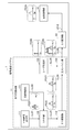
- FIG. 5 is a block diagram showing a detailed configuration example of the signal transmission system of FIG. 1 in an example in which the intermediate frequency / heterodyne method is adopted.
- the signal transmission system 1 of the example of FIG. 5 is the signal transmission system 1 of the example of FIG. 1, and further includes a local oscillation unit 131, a mixer unit 132, a laser generation unit 133, an optical combine unit 134, and a signal path LL21. To LL26.
- the functions and configurations of the Y-00 encryption output unit 111 in the example of FIG. 5 are basically the same as the functions and configurations of the Y-00 encryption output unit 111 in the example of FIG. 4, their description is omitted here. To do. That is, the frequencies included in the first electric signal have, for example, the distribution shown in the graph FE21, which is basically the same as the distribution shown in the graph FE11 in the example of FIG. 4, and thus the description thereof will be omitted here.
- the first electric signal output by the Y-00 encryption output unit 111 is transmitted to the mixer unit 132 via the signal path LL21.
- the local oscillation unit 131 oscillates a local oscillation signal corresponding to the intermediate frequency fIF described later.
- the local oscillation signal oscillated by the local oscillation unit 131 is transmitted to the mixer unit 132 via the signal path LL22.
- the intermediate frequency electric signal is transmitted to the E / O conversion unit 112 via the signal path LL23.
- the mixer unit 132 has a configuration according to the modulation method, and outputs an intermediate frequency electric signal from the first electric signal and the local oscillation signal. That is, the specific configuration of the mixer unit 132 may be configured according to a modulation method such as intensity modulation, amplitude modulation, phase modulation, frequency modulation, or orthogonal amplitude modulation.
- the frequencies included in the intermediate frequency electric signal output from the mixer unit 132 have, for example, the distribution shown in the graph FE22.
- the frequencies included in the optical signal have, for example, the distribution shown in the graph FO21, which is basically the same as the distribution shown in the graph FO11 in the example of FIG. 4, and thus the description thereof will be omitted here.
- the optical signal output by the E / O conversion unit 112 is transmitted to the optical combine unit 134 via the signal path LL 24 configured by an optical fiber or the like.
- the carrier light of the example of FIG. 4 is transmitted to the optical combine unit 134 via the signal path LL25 configured by an optical fiber or the like.
- the frequencies included in the carrier light generated from the laser generation unit 133 have the distribution shown in the graph FO23, for example.
- the optical combine unit 134 combines the optical signal and the carrier light. That is, it outputs a combined optical signal that combines both the optical signal transmitted via the signal path LL24 and the carrier light transmitted via the signal path LL25.
- the combined optical signal of the example of FIG. 5 is transmitted to the O / E conversion unit 13 via the signal path LL26 configured by an optical fiber or the like.
- the optical combine unit 134 may be configured by an optical power combiner, an optical wavelength division multiplexing device, or the like.
- the frequencies included in the combined optical signal output from the optical combine unit 134 have, for example, the distribution shown in the graph FO23.
- the O / E conversion unit 13 converts the combined optical signal into a second electric signal.
- the center frequency of the second electric signal is the frequency obtained by adding fIF.
- the functions and configurations of the radio wave transmitting unit 14 and the signal path LE 12 are basically the same as the functions and configurations of the radio wave transmitting unit 14 and the signal path LE 12 in FIG. The description is omitted. Further, the frequencies included in the second electric signal transmitted by the signal path LE12 are, for example, the distribution shown in the graph FE23, which is basically the same as the distribution shown in the graph FE12 in the example of FIG. The description is omitted. As a result, the radio wave transmission unit 14 transmits the encrypted signal of the second electric signal in the form of radio wave RW.
- an optical transmission medium such as an optical fiber and a component that operates a signal in an optical region such as an optical filter and an optical amplifier may be inserted as needed.
- components such as a filter and an amplifier in the fRF frequency band are provided in addition to a transmission medium such as an RF transmission cable, as in the example of FIG. It may be inserted as needed.
- the E / O converter 112 By converting to an intermediate frequency electric signal, the E / O converter 112 is relatively simple, such as a combination of a laser and a light intensity modulator (Machzenda modulator or electric field absorption type modulator) or direct modulation of the laser. It can be configured as such. That is, it is relatively simpler for the E / O conversion unit 112 to convert an intermediate frequency electric signal into an optical signal as compared with the case where the first electric signal generated in the baseband is converted into an optical signal. That is, it can be converted by a relatively inexpensive configuration.
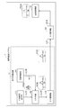
- FIG. 6 is a block diagram showing a detailed configuration example of the signal transmission system of FIG. 1 in which the analog / direct modulation method is adopted.
- the signal transmission system 1 of the example of FIG. 6 further includes a local oscillation unit 141, a mixer unit 142, and signal paths LL31 to LL33 in addition to the signal transmission system 1 of the example of FIG.
- the functions and configurations of the Y-00 encryption output unit 111 in the example of FIG. 6 are basically the same as the functions and configurations of the Y-00 encryption output unit 111 in the example of FIG. 4, their description is omitted here. To do. That is, the frequencies included in the first electric signal have, for example, the distribution shown in the graph FE31, which is basically the same as the distribution shown in the graph FE11 in the example of FIG. 4, and thus the description thereof will be omitted here.
- the first electric signal output by the Y-00 encryption output unit 111 is transmitted to the mixer unit 142 via the signal path LL31.
- the local oscillation unit 141 oscillates a local oscillation signal corresponding to the intermediate frequency fRF described later. That is, the local oscillation unit 141 of the example of FIG. 6 oscillates a local oscillation signal corresponding to fRF, which is the frequency of the radio wave RW, as an intermediate frequency.
- the local oscillation signal oscillated by the local oscillation unit 141 is transmitted to the mixer unit 142 via the signal path LL32.
- the intermediate frequency electric signal is transmitted to the E / O conversion unit 112 via the signal path LL33.
- the mixer unit 142 can be configured according to the modulation method, but since it is basically the same as the configuration example of the mixer unit 132 in the example of FIG. 5, their description is omitted here.
- the frequencies included in the intermediate frequency electric signal output from the mixer unit 142 have, for example, the distribution shown in the graph FE32.
- the frequencies included in the optical signal have, for example, the distribution shown in the graph FO3, which is basically the same as the distribution shown in the graph FO11 in the example of FIG. 4, and thus the description thereof will be omitted here.
- the optical signal output by the E / O conversion unit 112 is transmitted to the O / E conversion unit 13 via a signal path LO1 configured by an optical fiber or the like.
- the O / E conversion unit 13 converts an optical signal into a second electric signal.
- the functions and configurations of the radio wave transmitting unit 14 and the signal path LE 12 are basically the same as the functions and configurations of the radio wave transmitting unit 14 and the signal path LE 12 in FIG. The description is omitted.
- the frequencies included in the second electric signal transmitted by the signal path LE12 are, for example, the distribution shown in the graph FE33, which is basically the same as the distribution shown in the graph FE12 in the example of FIG. The description is omitted.
- the radio wave transmission unit 14 transmits the encrypted signal of the second electric signal in the form of radio wave RW.
- a signal is transmitted between the E / O conversion unit 112 and the O / E conversion unit 13 in an optical transmission medium such as an optical fiber or an optical region such as an optical filter or an optical amplifier, as in the example of FIG.
- Components that operate on may be inserted as needed.
- components such as a filter and an amplifier in the fRF frequency band are provided in addition to a transmission medium such as an RF transmission cable, as in the example of FIG. It may be inserted as needed.
- the E / O converter 112 By converting to an intermediate frequency electric signal, the E / O converter 112 is relatively simple, such as a combination of a laser and a light intensity modulator (Machzenda modulator or electric field absorption type modulator) or direct modulation of the laser. It can be configured as such. That is, it is relatively simpler for the E / O conversion unit 112 to convert an intermediate frequency electric signal into an optical signal as compared with the case where the first electric signal generated in the baseband is converted into an optical signal. That is, it can be converted by a relatively inexpensive configuration.
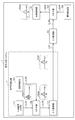
- FIG. 7 is a block diagram showing a detailed configuration example of the signal transmission system of FIG. 1 in which the analog / intermediate frequency method is adopted.
- the signal transmission system 1 of the example of FIG. 7 is the signal transmission system 1 of the example of FIG. 1, and further includes a local oscillation unit 151, a mixer unit 152, a local oscillation unit 153, a mixer unit 154, and a signal path LL41 to It is equipped with LL46.
- the functions and configurations of the Y-00 encryption output unit 111 in the example of FIG. 7 are basically the same as the functions and configurations of the Y-00 encryption output unit 111 in the example of FIG. 4, their description is omitted here.
- the frequencies included in the first electric signal have, for example, the distribution shown in the graph FE41, which is basically the same as the distribution shown in the graph FE11 in the example of FIG. 4, and thus the description thereof will be omitted here.
- the first electric signal output by the Y-00 encryption output unit 111 is transmitted to the mixer unit 152 via the signal path LL41.
- the functions and configurations of the local oscillator 151 and the mixer 152 in the example of FIG. 7 are basically the same as those of the functions and configurations of the local oscillator 131 and the mixer 132 in the example of FIG. Since there are some, their explanations are omitted here. That is, the frequencies included in the first electric signal and the intermediate frequency electric signal are, for example, the distributions shown in the graph FE41 and the graph FE42, respectively, and the distributions shown in the graph FE21 and the graph FE22 in the example of FIG. Since they are basically the same, their description is omitted here.
- the intermediate frequency electric signal is transmitted to the E / O conversion unit 112 via the signal path LL43.
- the local oscillation signal oscillated by the local oscillation unit 151 is hereinafter referred to as a “first local oscillation signal” in order to clearly distinguish it from the second local oscillation signal described later.
- the frequencies included in the optical signal have, for example, the distribution shown in the graph FO4, which is basically the same as the distribution shown in the graph FO11 in the example of FIG. 4, and thus the description thereof will be omitted here.
- the optical signal output by the E / O conversion unit 112 is transmitted to the O / E conversion unit 13 via a signal path LO1 configured by an optical fiber or the like.
- the O / E conversion unit 13 converts an optical signal into a second electric signal.
- the second electric signal output by the O / E conversion unit 13 is transmitted to the mixer unit 154 via the signal path LL44.
- the second local oscillation signal oscillated by the local oscillation unit 153 is transmitted to the mixer unit 154 via the signal path LL45.
- the mixer unit 154 can be configured according to the modulation method, but since it is basically the same as the configuration example of the mixer unit 132 in the example of FIG. 5, their description is omitted here.
- the frequencies included in the mixed electric signals output from the mixer unit 154 are, for example, the distribution shown in the graph FE43, which is basically the same as the distribution shown in the graph FE12 in the example of FIG. The description is omitted.
- the radio wave transmission unit 14 transmits the encrypted signal of the mixed electric signal in the form of the radio wave RW.
- an optical transmission medium such as an optical fiber and a component that operates a signal in an optical region such as an optical filter and an optical amplifier may be inserted as needed.
- components such as a filter and an amplifier in the fRF frequency band are provided in addition to a transmission medium such as an RF transmission cable, as in the example of FIG. It may be inserted as needed.
- a signal is transmitted between the E / O conversion unit 112 and the O / E conversion unit 13 in an optical transmission medium such as an optical fiber or an optical region such as an optical filter or an optical amplifier, as in the example of FIG.
- Components that operate on may be inserted as needed.
- the space between the O / E conversion unit 13 and the mixer unit 154 and between the mixer unit 154 and the radio wave transmission unit 14 in addition to the transmission medium such as the RF transmission cable, as in the example of FIG. Therefore, components such as filters and amplifiers in the frequency band of fRF may be inserted as needed.
- FIG. 8 is a block diagram showing a detailed configuration example of the signal transmission system of FIG. 1 in which the analog baseband method is adopted.
- the signal transmission system 1 of the example of FIG. 8 further includes a local oscillation unit 161 and a mixer unit 162, and signal paths LL51 to LL53, in addition to the signal transmission system 1 of the example of FIG.
- the functions and configurations of the Y-00 encryption output unit 111 of the example of FIG. 8 are basically the same as the functions and configurations of the Y-00 encryption output unit 111 of the example of FIG. 4, their description is omitted here. To do. That is, the frequencies included in the first electric signal have, for example, the distribution shown in the graph FE51, which is basically the same as the distribution shown in the graph FE11 in the example of FIG. 4, and thus the description thereof will be omitted here.
- the first electric signal output by the Y-00 encryption output unit 111 is transmitted to the E / O conversion unit 112 via the signal path LE11.
- the functions and configurations of the E / O conversion unit 112 of the example of FIG. 8 are basically the same as the functions and configurations of the E / O conversion unit 112 of the example of FIG. 4, their description will be omitted here. That is, the frequencies included in the optical signal have, for example, the distribution shown in the graph FO5, which is basically the same as the distribution shown in the graph FO11 in the example of FIG. 4, and thus the description thereof will be omitted here.
- the optical signal converted by the E / O conversion unit 112 is transmitted to the O / E conversion unit 13 via the signal path LO1 configured by an optical fiber or the like.
- the O / E conversion unit 13 converts an optical signal into a second electric signal.
- the second electric signal converted by the O / E conversion unit 13 is transmitted to the mixer unit 162 via the signal path LL51.
- the local oscillation unit 161 oscillates a local oscillation signal corresponding to the intermediate frequency fRF. That is, the local oscillation unit 161 in the example of FIG. 8 oscillates a local oscillation signal corresponding to fRF, which is the frequency of the radio wave RW, as an intermediate frequency.
- the local oscillation signal oscillated by the local oscillation unit 161 is transmitted to the mixer unit 162 via the signal path LL 52.
- the added center frequency f0 fRF. That is, the frequency of the radio wave RW to be transmitted is output as an electric signal mixed by the mixer unit 162.
- the mixed electric signal is transmitted to the radio wave transmission unit 14 via the signal path LL53.
- the mixer unit 162 can be configured according to the modulation method, but since it is basically the same as the configuration example of the mixer unit 132 in the example of FIG. 5, their description is omitted here.
- the frequencies included in the mixed electric signals output from the mixer unit 162 are, for example, the distribution shown in the graph FE52, which is basically the same as the distribution shown in the graph FE12 in the example of FIG. The description is omitted.
- the radio wave transmission unit 14 transmits the encrypted signal of the mixed electric signal in the form of the radio wave RW.
- a signal is transmitted between the E / O conversion unit 112 and the O / E conversion unit 13 in an optical transmission medium such as an optical fiber or an optical region such as an optical filter or an optical amplifier, as in the example of FIG.
- Components that operate on may be inserted as needed.
- the space between the O / E conversion unit 13 and the mixer unit 154 and between the mixer unit 154 and the radio wave transmission unit 14 in addition to the transmission medium such as the RF transmission cable, as in the example of FIG. Therefore, components such as filters and amplifiers in the frequency band of fRF may be inserted as needed.
- the signal transmission system 1 to which the present invention is applied has been described above.
- the signal transmission system 1 to which the present invention is applied is sufficient as long as it can output an electric signal having a large noise masking amount ⁇ in the form of a radio wave RW, and its configuration is limited to the above-mentioned various embodiments.
- it may be as follows.
- the signal transmission system 1 encrypts the signal to be transmitted and transmits it in the form of a radio wave RW, and the signal reception system 2 receives and decodes the radio wave RW. Therefore, the signal of the above-described form is received, but the present invention is not particularly limited to this.
- the signal processing system may have both a configuration related to transmission of radio wave RW and a configuration related to reception of radio wave RW, and may be capable of transmitting and receiving encrypted signals in the form of radio wave RW.
- the signal transmission / reception system is composed of the signal transmission system 1 and the signal reception system 2, but is not particularly limited thereto.
- a configuration may include a plurality of signal processing systems capable of transmitting and receiving encrypted signals in the form of radio wave RW.
- the signal processing system can form a network.
- the Y-00 encryption output unit 111 of the optical signal generation unit 11 uses the predetermined data to be transmitted as multi-valued information based on the Y-00 optical communication quantum cryptography protocol.
- multi-valued information is generated from the predetermined data to be transmitted and the private key based on the Y-00 optical communication quantum cryptography protocol, but the present invention is not particularly limited to this.
- the optical signal generation unit 11 may generate multi-valued information from predetermined data to be transmitted and a predetermined common key.
- multi-valued information may be generated from predetermined data to be transmitted and predetermined rules. That is, it suffices if the optical signal generation unit 11 can generate multi-valued information based on an arbitrary protocol.
- the noise masking amount ⁇ is "the number of symbol points within the range of the standard deviation when the distribution of shot noise is approximated as a Gaussian distribution", but the present invention is particularly limited to this. Not done. That is, the noise masking amount ⁇ is sufficient if it is the number of symbol points within an arbitrary noise range. Specifically, for example, the noise in the noise masking amount ⁇ may include any noise including classical noise such as thermal noise. Further, the range of the noise masking amount ⁇ is not limited to the range of the standard deviation when the noise distribution is approximated as a Gaussian distribution. Specifically, for example, the distribution obtained by actually measuring the noise may be acquired, and the variance of the acquired distribution may be used as the range. That is, the noise masking amount ⁇ is not limited to the above-mentioned equation (1), which is an equation when the phase modulation method is adopted.
- the distance between two adjacent symbol points is sufficiently smaller than the range of all noise including classical noise such as thermal noise. That is, for the optical signal generated by the optical signal generation unit 11, it is sufficient that the amount of noise masking by all "noise” including classical noise such as thermal noise is 1 or more.
- FIGS. 4 to 8 are used to illustrate a block showing a detailed configuration example in an example in which various methods are adopted in the signal transmission system 1, but the present invention is not particularly limited thereto.
- signal processing may be performed by providing a plurality of intermediate frequencies as intermediate frequencies.
- combining the laser beam by the optical combine unit and acquiring the beat component may be repeated a plurality of times. That is, the signal transmission system 1 can be configured to include an arbitrary number of mixer units and optical combine units.
- the signal path for transmitting the optical signals of FIGS. 1 and 3 to 8 (for example, the signal path LO1A of FIG. 1) is composed of an optical signal path by an optical communication cable.
- the signal path for transmitting the optical signal may be a path that propagates (transmits) the optical signal.
- a signal path spatial propagation that propagates an optical signal in the atmosphere or a vacuum can be adopted.
- the optical signal is converted by using the optical signal amplification unit 12 of FIG. 1 and the optical combine unit 122 of FIG. 4, but the present invention is not particularly limited to this. That is, as the type of conversion of the optical signal, various types of conversion can be adopted. For example, it may be amplification of an optical signal, branching of an optical signal, switching of an optical signal (switching of a path), extension of a transmission path of an optical signal, or combination of an optical signal.
- the signal processing device to which the present invention is applied is sufficient as long as it is as follows, and various various embodiments can be taken. That is, the signal processing system to which the present invention is applied (for example, the signal transmission system 1 in FIG. 1) is Optical generation that generates multi-valued information (multi-valued information generated based on the Y-00 optical communication quantum cryptography protocol) that takes a multi-valued state based on predetermined data (for example, predetermined data to be transmitted) as an optical signal.
- Means for example, the optical signal generation unit 11 in FIG. 1
- Photoelectric conversion means for example, O / E conversion unit 13 in FIG.
- a radio wave transmitting means for example, a radio wave transmitting unit 14 in FIG. 1 that transmits the multi-valued information converted into the electric signal as a radio wave (for example, the radio wave RW in FIG. 1).
- a signal processing system equipped with the above is sufficient.
- the light generating means is The multi-value information generating means (for example, the Y-00 encryption output unit 111 in FIG. 1) that generates the first electric signal of the multi-value information, An electro-optical conversion means for converting the first electric signal of the multi-valued information into an optical signal (for example, the E / O conversion unit 112 in FIG. 1) and Have, The photoelectric conversion means converts the optical signal into a second electric signal different from the first electric signal. be able to.
- the multi-value information generating means for example, the Y-00 encryption output unit 111 in FIG. 1
- An electro-optical conversion means for converting the first electric signal of the multi-valued information into an optical signal for example, the E / O conversion unit 112 in FIG. 1 and Have
- the photoelectric conversion means converts the optical signal into a second electric signal different from the first electric signal. be able to.
- multi-valued information based on predetermined data can be generated in the form of an electric signal. Further, the multi-valued information based on the predetermined data is converted from the form of the electric signal to the form of the optical signal.
- an optical conversion means for converting (for example, amplifying, branching, switching, extending, combining) the optical signal (for example, the optical signal amplification unit 12 in FIG. 1 and the optical combine unit 122 in FIG. 4).
- the photoelectric conversion means converts the optical signal converted by the optical conversion means. be able to.
- the noise of the optical signal increases due to various conversions (amplification and combine).
- an optical signal with increased noise is converted into an electric signal, the difficulty of correctly constructing data from the electric signal increases, and the effect of measures against eavesdropping at the physical layer is improved.
- the optical conversion means converts the optical signal into an optical signal containing components having different frequencies as compared with the optical signal.
- the photoelectric conversion means converts the optical signal converted by the optical conversion means into an electric signal that does not contain a component having a higher frequency than the optical signal. be able to.
- an optical signal is converted into an optical signal containing different components, and an optical signal containing components having different frequencies is converted into a second electric signal.
- an electric signal including a frequency component which is a beat component is generated.
- the beat component is basically a low frequency component as compared to the original frequency component.
- the higher the frequency of the optical signal the more effective the countermeasure against eavesdropping in the physical layer is. That is, in such a signal processing system, the optical signal having a higher frequency is used. The effect of measures against eavesdropping in the physical layer is improved, and it can be transmitted as a radio wave having a frequency lower than that of an optical signal.
- a second electric signal conversion means (for example, the local oscillator unit 153 and the mixer unit 154 in FIG. 7) that converts the second electric signal into an electric signal having a frequency different from that of the second electric signal.
- the radio wave transmitting means transmits the second electric signal converted by the second electric signal converting means as a radio wave. be able to.
- Such a signal processing system can convert the frequency of the second electric signal obtained by converting the optical signal into the frequency transmitted as radio waves. That is, the signal processing system generates noise at the frequency of the optical signal, so that the effect of measures against eavesdropping in the physical layer is improved by the optical signal, and the signal can be transmitted as a radio wave.
Landscapes
- Physics & Mathematics (AREA)
- Engineering & Computer Science (AREA)
- Computer Networks & Wireless Communication (AREA)
- Signal Processing (AREA)
- Electromagnetism (AREA)
- Optics & Photonics (AREA)
- Optical Communication System (AREA)
Priority Applications (1)
| Application Number | Priority Date | Filing Date | Title |
|---|---|---|---|
| US17/600,476 US11894875B2 (en) | 2019-04-04 | 2020-02-28 | Signal processing system |
Applications Claiming Priority (2)
| Application Number | Priority Date | Filing Date | Title |
|---|---|---|---|
| JP2019-071981 | 2019-04-04 | ||
| JP2019071981A JP6925645B2 (ja) | 2019-04-04 | 2019-04-04 | 信号処理システム |
Publications (1)
| Publication Number | Publication Date |
|---|---|
| WO2020202964A1 true WO2020202964A1 (ja) | 2020-10-08 |
Family
ID=72668840
Family Applications (1)
| Application Number | Title | Priority Date | Filing Date |
|---|---|---|---|
| PCT/JP2020/008530 Ceased WO2020202964A1 (ja) | 2019-04-04 | 2020-02-28 | 信号処理システム |
Country Status (3)
| Country | Link |
|---|---|
| US (1) | US11894875B2 (enExample) |
| JP (1) | JP6925645B2 (enExample) |
| WO (1) | WO2020202964A1 (enExample) |
Cited By (1)
| Publication number | Priority date | Publication date | Assignee | Title |
|---|---|---|---|---|
| JPWO2023181270A1 (enExample) * | 2022-03-24 | 2023-09-28 |
Citations (3)
| Publication number | Priority date | Publication date | Assignee | Title |
|---|---|---|---|---|
| JP2006080720A (ja) * | 2004-09-08 | 2006-03-23 | Tamagawa Gakuen | 暗号送信装置 |
| JP2007079096A (ja) * | 2005-09-14 | 2007-03-29 | Matsushita Electric Ind Co Ltd | 高周波信号生成方法及び高周波信号生成システム |
| JP2010114662A (ja) * | 2008-11-06 | 2010-05-20 | Hitachi Information & Communication Engineering Ltd | 光送信装置及び光送信方法 |
Family Cites Families (12)
| Publication number | Priority date | Publication date | Assignee | Title |
|---|---|---|---|---|
| US20060222180A1 (en) * | 2002-10-15 | 2006-10-05 | Elliott Brig B | Chip-scale transmitter for quantum cryptography |
| US7627126B1 (en) * | 2002-10-15 | 2009-12-01 | Bbn Technologies Corp. | Systems and methods for implementing path length control for quantum cryptographic systems |
| US20060263096A1 (en) * | 2005-05-17 | 2006-11-23 | Mihaela Dinu | Multi-channel transmission of quantum information |
| US20070172058A1 (en) * | 2006-01-25 | 2007-07-26 | Tomokazu Sada | Data transmitting apparatus and data receiving apparatus |
| JP2007274300A (ja) * | 2006-03-31 | 2007-10-18 | Hitachi Information & Communication Engineering Ltd | 共通鍵暗号通信における同期処理方法 |
| US8116638B2 (en) * | 2006-05-30 | 2012-02-14 | Harris Corporation | Radio frequency (RF) signal receiver using optical processing and associated methods |
| JP4860708B2 (ja) * | 2006-12-27 | 2012-01-25 | 富士通株式会社 | ストリーム暗号方法および暗号システム |
| JP2012058019A (ja) * | 2010-09-07 | 2012-03-22 | Olympus Corp | 光検出装置および光検出方法、並びに、顕微鏡および内視鏡 |
| JP5170586B2 (ja) | 2010-10-08 | 2013-03-27 | 学校法人玉川学園 | Yuen暗号用光送信装置及び受信装置、Yuen暗号光送信方法及び受信方法、並びに暗号通信システム |
| JP6281303B2 (ja) * | 2014-02-03 | 2018-02-21 | 富士通株式会社 | 多値強度変復調システムおよび方法 |
| KR102322046B1 (ko) * | 2015-03-24 | 2021-11-08 | 한국전자통신연구원 | 아날로그 RoF 기반 모바일 프론트홀에서 제어 신호 송/수신 장치 및 방법 |
| KR102415308B1 (ko) * | 2016-02-25 | 2022-07-01 | 한국전자통신연구원 | 분산 관리 기법을 이용한 아날로그 광 전송 시스템 |
-
2019
- 2019-04-04 JP JP2019071981A patent/JP6925645B2/ja active Active
-
2020
- 2020-02-28 US US17/600,476 patent/US11894875B2/en active Active
- 2020-02-28 WO PCT/JP2020/008530 patent/WO2020202964A1/ja not_active Ceased
Patent Citations (3)
| Publication number | Priority date | Publication date | Assignee | Title |
|---|---|---|---|---|
| JP2006080720A (ja) * | 2004-09-08 | 2006-03-23 | Tamagawa Gakuen | 暗号送信装置 |
| JP2007079096A (ja) * | 2005-09-14 | 2007-03-29 | Matsushita Electric Ind Co Ltd | 高周波信号生成方法及び高周波信号生成システム |
| JP2010114662A (ja) * | 2008-11-06 | 2010-05-20 | Hitachi Information & Communication Engineering Ltd | 光送信装置及び光送信方法 |
Non-Patent Citations (1)
| Title |
|---|
| TANIZAWA, KEN ET AL.: "Photonic Generation of Quantum Noise Assisted Cipher at Microwave Frequencies for Secure Wireless Links", 2020 OPTICAL FIBER COMMUNICATIONS CONFERENCE AND EXHIBITION(OFC, 13 May 2020 (2020-05-13), XP033767268, ISBN: 978-1-9435-8071-2, Retrieved from the Internet <URL:https://ieeexplore.ieee.org/stamp/stamp.jsp?tp=&arnumber=9083118> [retrieved on 20200601] * |
Cited By (1)
| Publication number | Priority date | Publication date | Assignee | Title |
|---|---|---|---|---|
| JPWO2023181270A1 (enExample) * | 2022-03-24 | 2023-09-28 |
Also Published As
| Publication number | Publication date |
|---|---|
| JP6925645B2 (ja) | 2021-08-25 |
| US20220173809A1 (en) | 2022-06-02 |
| US11894875B2 (en) | 2024-02-06 |
| JP2020170960A (ja) | 2020-10-15 |
Similar Documents
| Publication | Publication Date | Title |
|---|---|---|
| US10574447B2 (en) | Antenna array based OAM wireless communication | |
| Huang et al. | Implementation vulnerabilities in general quantum cryptography | |
| US10389526B2 (en) | Methods for quantum key distribution and related devices | |
| US8281126B2 (en) | Out of band encryption | |
| CN110995404B (zh) | 一种基于混沌加密的太赫兹保密通信系统 | |
| JP5377934B2 (ja) | 光送信装置 | |
| Wang et al. | Photonics-based integrated radar jamming and secure communication system at Ka-band | |
| CN109617687A (zh) | 一种可见光通信的量子加密系统 | |
| WO2015166719A1 (ja) | 物理レイヤ暗号化装置及び方法 | |
| CN118233013A (zh) | 通信感知系统及方法 | |
| EP1726118A1 (en) | Secure data communication apparatus and method | |
| JP6850516B2 (ja) | 信号処理装置 | |
| JP6925645B2 (ja) | 信号処理システム | |
| JP5020999B2 (ja) | 量子暗号通信装置および量子暗号通信方法 | |
| CN116192284B (zh) | 一种用于在光通信系统物理层中无痕加密的装置及方法 | |
| US12119879B2 (en) | Signal processing device | |
| CN107911171B (zh) | 基于相干激光跳频通信的发射端、接收端、系统及方法 | |
| RU2447598C1 (ru) | Когерентная радиолиния | |
| JP5062642B2 (ja) | 暗号光送信装置及び受信装置、暗号光送信方法及び受信方法、並びに暗号通信システム | |
| Ahmed et al. | Increase security of li-fi technology by using RSA algorithm to encryption and decryption important data | |
| US20250226892A1 (en) | Signal processing system | |
| CN115412237B (zh) | 一种基于色散-双环自相位加密的硬件保密通信系统和方法 | |
| RU2735923C1 (ru) | Когерентная радиолиния | |
| JP7430942B2 (ja) | 信号処理システム | |
| Verma et al. | Secure Transmission with One-Time Pad Encryption Using FDM-Based CV-QKD in VLC System |
Legal Events
| Date | Code | Title | Description |
|---|---|---|---|
| 121 | Ep: the epo has been informed by wipo that ep was designated in this application |
Ref document number: 20783609 Country of ref document: EP Kind code of ref document: A1 |
|
| NENP | Non-entry into the national phase |
Ref country code: DE |
|
| 122 | Ep: pct application non-entry in european phase |
Ref document number: 20783609 Country of ref document: EP Kind code of ref document: A1 |