WO2020202964A1 - 信号処理システム - Google Patents
信号処理システム Download PDFInfo
- Publication number
- WO2020202964A1 WO2020202964A1 PCT/JP2020/008530 JP2020008530W WO2020202964A1 WO 2020202964 A1 WO2020202964 A1 WO 2020202964A1 JP 2020008530 W JP2020008530 W JP 2020008530W WO 2020202964 A1 WO2020202964 A1 WO 2020202964A1
- Authority
- WO
- WIPO (PCT)
- Prior art keywords
- signal
- optical
- unit
- electric signal
- radio wave
- Prior art date
Links
Images

Classifications
-
- H—ELECTRICITY
- H04—ELECTRIC COMMUNICATION TECHNIQUE
- H04B—TRANSMISSION
- H04B10/00—Transmission systems employing electromagnetic waves other than radio-waves, e.g. infrared, visible or ultraviolet light, or employing corpuscular radiation, e.g. quantum communication
- H04B10/70—Photonic quantum communication
-
- H—ELECTRICITY
- H04—ELECTRIC COMMUNICATION TECHNIQUE
- H04B—TRANSMISSION
- H04B10/00—Transmission systems employing electromagnetic waves other than radio-waves, e.g. infrared, visible or ultraviolet light, or employing corpuscular radiation, e.g. quantum communication
- H04B10/25—Arrangements specific to fibre transmission
- H04B10/2575—Radio-over-fibre, e.g. radio frequency signal modulated onto an optical carrier
-
- H—ELECTRICITY
- H04—ELECTRIC COMMUNICATION TECHNIQUE
- H04K—SECRET COMMUNICATION; JAMMING OF COMMUNICATION
- H04K1/00—Secret communication
- H04K1/02—Secret communication by adding a second signal to make the desired signal unintelligible
Definitions
- the present invention relates to a signal processing system.
- the network systems that make up the Internet are described by the OSI reference model developed by the International Organization for Standardization.
- OSI reference model developed by the International Organization for Standardization.
- the physical layer of layer 1 and the application layer of layer 7 are separated, and the interface connecting each layer is standardized or standardized by de facto.
- the lowest layer is the physical layer, which plays the role of actually transmitting and receiving signals by wire or wireless.
- security (often relying on mathematical cryptography) is implemented at layer 2 or higher, and no security measures are taken at the physical layer. However, there is a risk of eavesdropping even in the physical layer.
- optical fiber communication which is a typical example of wired communication
- Patent Document 1 it is possible to take measures against eavesdropping in the physical layer using an optical fiber by transmitting multi-valued information as an optical signal, but the physical layer in wireless communication. It was not possible to take measures against eavesdropping in.
- An object of the present invention is to take measures against eavesdropping at the physical layer in wireless communication.
- the signal processing system of one aspect of the present invention is An optical generating means that generates multi-valued information that takes a multi-valued state based on predetermined data as an optical signal, and Photoelectric conversion means for converting the optical signal into an electric signal, A radio wave transmitting means for transmitting the multi-valued information converted into the electric signal as a radio wave, and To be equipped.
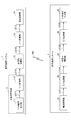
- FIG. 1 is a block diagram showing an example of a configuration of a signal transmission / reception system according to an embodiment of the signal processing system of the present invention.
- the signal transmission / reception system of the example of FIG. 1 is configured to include a signal transmission system 1 and a signal reception system 2.
- the signal transmission system 1 encrypts the signal to be transmitted based on the Y-00 optical communication quantum cryptography protocol and transmits it in the form of radio wave RW.
- the signal receiving system 2 receives the radio wave RW, decodes it based on the protocol of Y-00 optical communication quantum cryptography, and receives the signal of the above-mentioned form.
- the Y-00 optical communication quantum cryptography is based on the Y-00 optical communication quantum cryptography protocol, and after converting predetermined data to be transmitted into multi-valued information, it is transmitted as an optical signal.
- This is an encryption method based on the principle that the received signal becomes an encrypted encrypted signal.
- the signal transmission system 1 is configured to include an optical signal generation unit 11, an optical signal amplification unit 12, an O / E conversion unit 13, and a radio wave transmission unit 14.
- the optical signal generation unit 11 generates multi-valued information in a multi-valued state based on predetermined data as an optical signal.
- This optical signal is a signal to be transmitted, the details of which will be described later.
- the optical signal generation unit 11 includes a Y-00 encryption output unit 111 and an E / O conversion unit 112.
- the Y-00 encryption output unit 111 is an electric signal of multi-valued information that takes a multi-valued state based on predetermined data (hereinafter, "first electric signal” in order to clearly distinguish it from the second to fourth electric signals described later. Is called). That is, the Y-00 encryption output unit 111 generates predetermined data to be transmitted or acquires it from a generator (not shown). Using this predetermined data, the Y-00 encryption output unit 111 uses the multi-valued information generated based on the Y-00 optical communication quantum cryptography protocol to provide the signal path LE11 in the form of a first electric signal as the multi-valued information. Output via.
- predetermined data hereinafter, "first electric signal” in order to clearly distinguish it from the second to fourth electric signals described later. Is called. That is, the Y-00 encryption output unit 111 generates predetermined data to be transmitted or acquires it from a generator (not shown). Using this predetermined data, the Y-00 encryption output unit 111 uses the multi-value
- the first electric signal in the signal path LE11 may be either an analog signal or a digital signal, but in the description of the present embodiment, it will be described as an analog signal.
- the signal path LE11 has a configuration capable of transmitting a plurality of bits (for example, from a plurality of signal paths for transmitting signals in parallel or a data processing unit for transmitting signals serially). The configuration) is appropriately provided.
- the E / O conversion unit 112 converts the first electric signal of the multi-valued information output from the Y-00 encryption output unit 111 into an optical signal. That is, the E / O conversion unit 112 converts the first electric signal of the multi-value information input via the LE 11 into an optical signal modulated by an arbitrary modulation method and outputs it via the signal path LO1A.
- the signal path LO1A may be composed of an optical signal path using an optical communication cable.
- the optical communication cable By using the optical communication cable as the signal path LO1A in this way, in the signal transmission system 1, the E / O conversion unit 112 and the O / E conversion unit 13 described later can be installed at a distance.
- the optical signal amplification unit 12 amplifies the optical signal generated from the E / O conversion unit 112. That is, the optical signal amplification unit 12 amplifies and outputs an optical signal generated from the E / O conversion unit and transmitted by the signal path LO1A.
- the optical signal (amplified optical signal) output from the optical signal amplification unit 12 is transmitted to the O / E conversion unit 13 via the signal path LO1B.
- the signal path LO1B may be composed of an optical signal path by an optical communication cable, similarly to the signal path LO1A. That is, the optical signal amplification unit 12 can be used as a repeater in the optical signal path capable of amplifying the attenuated optical signal by passing through the signal path LO1A.
- the optical signal amplification unit 12 can be used as such a repeater, the distance of the optical signal path between the E / O conversion unit 112 and the O / E conversion unit 13 described later can be extended. In other words, the E / O conversion unit 112 and the O / E conversion unit 13 described later can be installed at a further distance from each other.
- the O / E conversion unit 13 clearly defines the optical signal amplified by the optical signal amplification unit 12 and transmitted by the signal path LOB as an electric signal (the first electric signal described above and the third and fourth electric signals described later). In order to distinguish between the above, it is converted into a "second electric signal"). That is, the O / E conversion unit 13 transfers the optical signal corresponding to the multi-valued information generated based on the Y-00 optical communication quantum cryptography protocol to the optical signal transmitted by the signal path LO1. Converts to an electric signal and outputs it. The second electric signal output from the O / E conversion unit 13 is transmitted to the radio wave transmission unit 14 via the signal path LE12.
- the second electric signal is converted from the optical signal by the O / E conversion unit 13, and as a result, becomes an electric signal including shot noise. That is, the signal is encrypted (hereinafter referred to as "encrypted signal") according to the principle of Y-00 optical communication quantum cryptography described later.
- the encrypted signal cannot correctly reconstruct the data unless it is decrypted in the Y-00 optical communication quantum cryptography protocol. That is, even if the second electric signal is intercepted by a third party, it is difficult for the third party to decipher it.
- the term of the encrypted signal refers to an encrypted signal regardless of the form of an electric signal, an optical signal, a radio wave, or the like.
- the optical signal amplification unit 12 is shown by a broken line. This is because the optical signal amplification unit 12 is not an indispensable component for the signal transmission system 1, and even if the optical signal amplification unit 12 is included in the component, the number is not limited to one and is arbitrary. It means that the number is sufficient. That is, when the distance of the optical transmission line between the E / O conversion unit 112 and the O / E conversion unit 13 becomes long, the number of optical signal amplification units 12 serving as relay units in the optical transmission line is increased. Can be introduced individually.
- the signal transmission system 1 may be configured not to include the optical signal amplification unit 12.
- the signal transmission system 1 is configured not to include the optical signal amplification unit 12, and the E / O conversion unit 112 and the O / E conversion unit 13 are directly connected to each other in a signal path. It is assumed that they are connected via LO1A and signal path LO1B (hereinafter, these are collectively referred to as "signal path LO1").
- the radio wave transmission unit 14 transmits the encrypted signal converted into the second electric signal by the O / E conversion unit 13 and transmitted by the signal path LE 12 in the form of radio wave RW. That is, the radio wave transmission unit 14 transmits the second electric signal, which is an encrypted signal, as a radio wave RW via a component such as an antenna after performing control such as predetermined amplification and frequency conversion. That is, the second electric signal transmitted in the form of radio wave RW is an encrypted signal.
- the electric signal of the radio wave RW acquired by a third party converts the multi-valued information generated based on the Y-00 optical communication quantum cryptography protocol into an optical signal, and further converts the optical signal into a second electric signal. It is an encrypted signal converted into a signal. That is, it is difficult to decipher the electric signal of the radio wave RW acquired by a third party.
- the configuration example of the signal transmission system 1 that transmits the encrypted signal encrypted based on the Y-00 optical communication quantum cryptography protocol in the form of the radio wave RW has been described above.
- a configuration example of the signal receiving system 2 that receives the radio wave RW and decodes it based on the Y-00 optical communication quantum cryptography protocol will be described.
- the signal receiving system 2 is configured to include a radio wave receiving unit 21, an E / O conversion unit 22, an optical signal amplification unit 23, an O / E conversion unit 24, and a Y-00 encryption input unit 25. There is.
- the radio wave receiving unit 21 receives the radio wave RW transmitted by the signal transmission system 1. That is, the radio wave receiving unit 21 receives the encrypted signal in the form of radio wave RW with an antenna or the like, and in order to clearly distinguish it from the electric signals (the first and second electric signals described above and the fourth electric signal described later), the following, It is output in the form of "third electric signal”).
- the third electric signal output from the radio wave receiving unit 21 is transmitted to the E / O conversion unit 22 via the signal path LE 21.
- the E / O conversion unit 22 converts the third electric signal corresponding to the radio wave RW received by the radio wave receiving unit 21 into an optical signal. That is, the E / O conversion unit 22 converts the encrypted signal in the form of the third electric signal received by the radio wave receiving unit 21 and transmitted by the signal path LE 21 into the form of an optical signal and outputs it.
- the third electric signal output from the E / O conversion unit 22 is transmitted to the optical signal amplification unit 23 via the signal path LO2A.
- the signal path LO2A may be composed of an optical signal path using an optical communication cable.
- the optical communication cable By using the optical communication cable as the signal path LO2A in this way, in the signal receiving system 2, the E / O conversion unit 22 and the O / E conversion unit 24 described later can be installed at a distance.
- the optical signal amplification unit 23 amplifies the optical signal converted by the E / O conversion unit 22. That is, the optical signal amplification unit 23 amplifies and outputs an optical signal that has been converted by the E / O conversion unit and transmitted by the signal path LO2A.
- the optical signal (amplified optical signal) output from the optical signal amplification unit 23 is transmitted to the O / E conversion unit 24 via the signal path LO2B.
- the signal path LO2B may be composed of an optical signal path by an optical communication cable, similarly to the signal path LO2A. That is, the optical signal amplification unit 23 can be used as a repeater in the optical signal path capable of amplifying the attenuated optical signal by passing through the signal path LO2A.
- the optical signal amplification unit 23 which is such a repeater, the distance of the optical signal path between the E / O conversion unit 22 and the O / E conversion unit 24 described later can be extended. In other words, the E / O conversion unit 22 and the O / E conversion unit 24, which will be described later, can be installed at a further distance from each other.
- the optical signal amplification unit 23 is shown by a broken line. This is because the optical signal amplification unit 23 is not an indispensable component for the signal receiving system 2, and even if the optical signal amplification unit 23 is included in the components, the number is not limited to one and is arbitrary. It means that the number is sufficient. That is, when the distance of the optical transmission line between the E / O conversion unit 22 and the O / E conversion unit 24 becomes long, there are a plurality of optical signal amplification units 23 as relay units in the optical transmission line. Can be introduced individually. On the other hand, when the distance of the optical transmission line between the E / O conversion unit 22 and the O / E conversion unit 24 is shortened, the optical signal generated from the E / O conversion unit 22 is used.
- the signal receiving system 2 can be configured not to include the optical signal amplification unit 23.
- the signal receiving system 2 is configured not to include the optical signal amplification unit 23, and the E / O conversion unit 22 and the O / E conversion unit 24 are directly connected to each other in a signal path. It is assumed that they are connected via LO2A and signal path LO2B (hereinafter, these are collectively referred to as "signal path LO2").
- the O / E conversion unit 24 describes the optical signal amplified by the optical signal amplification unit 12 and transmitted by the signal path LO2 as an electric signal (hereinafter, in order to clearly distinguish it from the first to third electric signals described above). It is converted into a "fourth electric signal"). That is, the O / E conversion unit 24 converts an optical signal corresponding to the encrypted signal of the radio wave RW and transmitted by the optical transmission line including the signal path LO2 into a fourth electric signal and outputs the signal. To do.
- the fourth electric signal output from the O / E conversion unit 24 is transmitted to the Y-00 encryption input unit 25 via the signal path LE 22.
- the Y-00 encryption input unit 25 inputs an encryption signal in the form of a fourth electric signal converted by the O / E conversion unit 24 via the signal path LE22, and is based on the Y-00 optical communication quantum cryptography protocol. By decoding, it is converted into predetermined data that was the transmission target. Further, the Y-00 encryption input unit 25 acquires the decrypted predetermined data or provides it to a reception destination (not shown).
- the radio wave receiving unit 21 and the Y-00 encryption input unit 25 are installed close to each other, the radio wave receiving unit 21 and the Y-00 encryption input unit 25 are directly connected to the signal path LE21 and the signal path LE21. It may be connected via the signal path LE22. That is, the third electric signal can be directly adopted as the fourth electric signal and input to the Y-00 encryption input unit 25.
- optical fiber communication which is a typical wired communication, is adopted as the communication method of the optical signal.
- a third party introduces a branch into the optical fiber and extracts a part of the signal power to obtain a large amount of information (encrypted signal here, hereinafter referred to as "encrypted signal"). In principle, it is possible to steal all at once.
- the Y-00 optical communication quantum cryptography is a quantum cryptography associated with the particle nature of light, and can be applied to optical fiber communication. On the other hand, it could not be applied to communication having extremely small quantum property compared to light, such as wireless communication using radio wave RW.
- the signal transmission system 1 and the signal reception system 2 transmit / receive information (encrypted signal) by wireless communication. Therefore, in the example of FIG. 1, the encrypted signal is transmitted and received by the signal transmission system 1 and the signal reception system 2 in the form of a radio wave RW for wireless communication.
- the signal transmission / reception system of the present embodiment is configured to be able to solve such a problem.
- a method for solving such a problem will be described.
- the Y-00 optical communication quantum cryptography is characterized in that "the ciphertext cannot be obtained correctly due to the effect of quantum noise", and was developed by the applicant.
- the data (plaintext) to be transmitted is represented by one or more aggregates of bit data of "0" or "1".
- Each bit data constituting the transmission data is modulated to a predetermined value among M values (M is an integer value of 2 or more) by a predetermined algorithm. Therefore, hereinafter, this numerical value M is referred to as "modulation number M".
- Y-00 optical communication quantum encryption at least one of the phase and amplitude of the optical signal (carrier wave) is modulated bit by bit by the encryption key on the encryption side and the decryption side to one of the values of the modulation number M. Encrypts the transmitted data (plain text).
- the modulation number M is set to an extremely large value, the feature that "the ciphertext cannot be correctly acquired due to the effect of quantum noise" is realized.
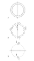
- Japanese Patent Application Laid-Open No. 2012-085028 may be referred to. Therefore, here, the outline of the principle of Y-00 optical communication quantum cryptography will be briefly described with reference to FIGS. 2 and 3 by taking phase modulation as an example.
- FIG. 2 is a diagram illustrating an outline of the principle of Y-00 optical communication quantum cryptography.
- an IQ plane representing the phase and amplitude (intensity) of an optical signal is drawn with the intersection of the vertical axis and the horizontal axis as the origin.
- the phase and amplitude of the optical signal are uniquely determined.
- the phase is an angle formed by a line segment whose starting point is the origin of the IQ plane and whose ending point is a point representing the optical signal, and a line segment representing phase 0.
- the amplitude is the distance between the point representing the Shinko number and the origin of the IQ plane.
- FIG. 2A is a diagram illustrating the principle of ordinary binary modulation in order to facilitate the understanding of Y-00 optical communication quantum cryptography.
- the plaintext transmission data
- the optical signal carrier wave
- the binary values shown in FIG. 2A are obtained for each of the bit data (1 or 0) constituting the plaintext. Modulation shall be performed.
- the bit data is "0”
- the arrangement of the points indicating the optical signal after phase modulation (hereinafter referred to as "symbol points") is 0 (0) on the right side on the horizontal axis. ), That is, the phase is 0.
- the arrangement of the symbol points after phase modulation is the arrangement of the symbol points S12 with ⁇ (1) on the left side on the horizontal axis, that is, the arrangement of the phase of ⁇ .
- the solid circle surrounding the symbol point S11 shows an example of the fluctuation range of the quantum noise when the optical signal of the symbol point S11 is received.
- an example of the fluctuation range of the quantum noise is shown as a solid circle surrounding the symbol point S12.
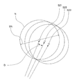
- one of eight random values is generated by using the encryption key for each bit data constituting the plaintext.
- the phase of the normal binary modulation symbol point (point of phase 0 corresponding to 0 or point of phase ⁇ corresponding to 1) shown in FIG. 2A was randomly generated out of 8 values.
- shot noise Quantum noise
- the position of the original symbol point becomes difficult to determine from the phase information measured on the receiving side. That is, for example, it is assumed that the phase measured on the receiving side at a certain time corresponds to the position of the symbol point S22 shown in FIG. In this case, is it transmitted as an optical signal of the symbol point S22, or what is actually transmitted as an optical signal of the symbol point S21 or the symbol point S23 is measured as the symbol point S22 due to the influence of shot noise. It is indistinguishable whether it was done.
- phase modulation is used in the examples of FIGS. 2 and 3
- amplitude (intensity) modulation may be used instead of or in combination with this. That is, for the modulation of the optical signal using the Y-00 protocol, any modulation method such as intensity modulation, amplitude modulation, phase modulation, frequency modulation, and orthogonal amplitude modulation can be adopted.
- the Y-00 optical communication quantum cryptography makes it possible to make the distance D between the two symbol points sufficiently smaller than the shot noise range SN in any modulation method, and "quantum noise It can have the feature that the ciphertext cannot be obtained correctly due to the effect.
- quantum noise guarantees safety, but in reality, eavesdroppers obtain the correct ciphertext by the effect of all "noise” including classical noise such as thermal noise in addition to quantum noise. Will prevent you from doing so.
- the noise masking amount ⁇ is defined and described as the noise masking amount ⁇ .
- the concept of the noise masking amount ⁇ is a concept that can be applied to other than the distribution of shot noise. A method of applying the concept of noise masking amount ⁇ to other noise will be described later.
- the noise masking amount ⁇ of this example adopts the distance (radius) corresponding to the shot noise range SN described above in FIG. 2 and the standard deviation of the Gaussian distribution of shot noise.
- the noise masking amount ⁇ is the number of other symbol points included in the shot noise range SN. That is, the noise masking amount ⁇ indicates the number of other symbol points whose distance D is smaller than the shot noise range SN with respect to a certain symbol point. That is, the noise masking amount ⁇ is an amount proportional to the encryption strength of the encrypted signal.
- the noise masking amount ⁇ is represented by the following equation (1). ... (1)
- the modulation number M is the number of phase candidates to be modulated for encryption.
- the symbol rate R is a number indicating how many symbol points are sent per unit time.
- Planck's constant h is a physical constant and is a proportional constant related to the energy and frequency of a photon.
- the frequency ⁇ 0 is the frequency of the signal.
- the power P0 is a number representing the power of the signal.
- the noise masking amount ⁇ is a sufficiently large value, masking by shot noise works. That is, the Y-00 photon cryptography works effectively as a cipher. Specifically, for example, when this value is 1 or more, the effect of masking by shot noise is exhibited, and when it is a sufficiently large value, even higher safety is achieved.
- the noise masking amount ⁇ is proportional to the square root of the signal frequency ⁇ 0. In other words, when the frequency ⁇ 0 of the carrier wave is low, the noise masking amount ⁇ becomes small, and the security of encryption becomes low.
- the frequency ⁇ 0 used in optical fiber transmission is 200 [THz] (wavelength is approximately 1.55 [um]).
- the frequency ⁇ 0 used in long-wave wireless communication is 100 [kHz].
- the frequency ⁇ 0 used in wireless communication by microwave has 10 [GHz].
- an example of comparing the noise masking amount ⁇ under the condition that the frequency other than the frequency ⁇ 0 does not change is as follows.
- the condition that the frequency other than the frequency ⁇ 0 does not change is the condition that the symbol rate R and the power P0 are the same.
- the ratio of the noise masking amount ⁇ of wireless communication by the long wave divided by the noise masking amount ⁇ of optical fiber transmission is about 1 / 45,000.
- the ratio of the noise masking amount ⁇ of wireless communication by microwaves divided by the noise masking amount ⁇ of optical fiber transmission is about 1/140.
- the signal transmission / reception system of the present embodiment can also encrypt the radio wave RW in wireless communication in the physical layer. That is, the signal transmission system 1 of the above-described embodiment is a system (a system configured based on such a mechanism) capable of applying the Y-00 optical communication quantum cryptography to wireless communication.
- the signal form of the predetermined data to be transmitted is converted by undergoing various conversions.
- the encrypted signal of FIG. 1 is transmitted in the form of radio wave RW.
- a mechanism for transmitting an encrypted signal including a timing at which predetermined data becomes an encrypted signal by Y-00 optical communication quantum cryptography will be described.
- the optical signal generation unit 11 generates multi-value information that takes a multi-value state based on predetermined data as an optical signal. Further, even if the generated optical signal is intercepted by a third party, the ciphertext cannot be correctly acquired due to the effect of shot noise. Specifically, for example, a third party who intercepts the optical signal of the signal path LO1 acquires the optical signal as an electric signal by O / E conversion. At the timing of O / E conversion, shot noise is generated due to the particle nature of light. As a result, a third party who does not have the Y-00 optical communication quantum cryptography algorithm and its encryption key cannot decrypt the electric signal and correctly obtain the ciphertext.
- the signal transmission system 1 of the example of FIG. 1 converts an optical signal into a second electric signal by the O / E conversion unit 13. That is, similarly to the O / E conversion by a third party described above, at the timing of the O / E conversion in the O / E conversion unit 13, the second electric signal becomes an electric signal in which shot noise is generated. Further, the signal transmission system 1 transmits a second electric signal from the radio wave transmission unit 14. As a result, the radio wave RW is encrypted including shot noise based on the frequency of the optical signal. That is, since shot noise is generated based on the frequency of the optical signal instead of the frequency of the radio wave RW, the electric signal has a large noise masking amount ⁇ .
- the mechanism by which the Y-00 optical communication quantum cryptography can be applied to wireless communication has been described.
- the transmission target The predetermined data is encrypted and becomes an encrypted signal.
- the signal path LO1 can be configured by a long-distance optical fiber or the like. That is, for example, in the case of a long-distance optical fiber, even when a third party works on the optical fiber to intercept the optical signal, the optical signal is encrypted, thus ensuring safety. can do.
- the optical signal generation unit 11 and the E / O conversion unit 13 can be provided at separate positions.
- the optical signal amplification unit 12 when the optical signal amplification unit 12 amplifies the optical signal, noise is added to the optical signal after output. As a result, by adding noise in addition to the shot noise described above, the optical signal is encrypted with a larger noise even when a third party acquires the signal in the signal path LO1A or later. Therefore, it is difficult to decipher.
- the first electric signal is converted into an optical signal by direct modulation of the laser or E / O conversion performed by a combination of the laser and various modulation elements.
- the E / O conversion unit 112 includes a laser light source (not shown).
- the laser light source of the E / O converter 112 generates a monochromatic (unmodulated) carrier wave of frequency fsig.
- the E / O conversion unit 112 converts the first electric signal into an optical signal.
- the radio wave transmission unit 14 can obtain an electric signal having a frequency of the radio wave RW used in wireless communication.
- a radio wave relay device (not shown) may be configured to relay the radio wave RW as a radio wave having a different center frequency.
- the signal transmission / reception system is configured to include the signal transmission system 1 and the signal reception system 2, but the signal transmission system 1 is provided with a function related to signal reception. It may be a signal processing system capable of transmitting and receiving. In this case, in a transmission / reception system including two or more signal processing systems, communication can be performed by an encrypted signal in the form of radio wave RW regardless of the direction of communication.
- the encryption signal may be used in only one direction.
- the configuration in the signal processing system and the configuration of transmission and reception do not necessarily have to be symmetrical.
- the signal when the signal receiving system is an antenna relay station, the signal may be transmitted by the antenna (radio wave transmitting unit) again after receiving the signal by the antenna (radio wave receiving unit) and performing an operation such as amplification.
- the signal receiving system 2 when the signal receiving system 2 is a terminal such as a PC, it is assumed that there is no E / O conversion or O / E conversion, and only electrical processing is performed. That is, the third electric signal received by the radio wave receiving unit 21 may be input to the Y-00 encryption input unit 25. At that time, the third electric signal may be appropriately converted to a center frequency suitable for the Y-00 encryption input unit 25.
- RW radio wave
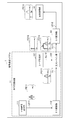
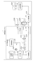
- FIG. 4 is a block diagram showing a detailed configuration example of the signal transmission system of FIG. 1 in which the baseband heterodyne method is adopted.
- the signal transmission system 1 of the example of FIG. 4 further includes a laser generation unit 121, an optical combine unit 122, and signal paths LL11 to LL13 connecting each of the signal transmission system 1 of the example of FIG.
- the Y-00 encryption output unit 111 is a multi-valued device for modulating at least one of the optical phase and the optical amplitude from the predetermined data to be transmitted and the private key based on the Y-00 optical communication quantum encryption protocol.
- the frequencies included in the first electric signal have, for example, the distribution shown in the graph FE11.
- the distribution shown in the graph FE11 conceptually shows the frequencies included in the signal.
- the distribution shown in the graph FE11 has a frequency f on the horizontal axis.
- the arrows, hemispherical shapes, and the like in the distributions shown in the graphs have the same meanings as those in the graph FE11 described above.
- the first electric signal is a signal containing information for modulating at least one of the phase of light and the amplitude of light.
- the optical signal of the example of FIG. 4 is transmitted to the optical combine unit 122 via the signal path LL11 configured by an optical fiber or the like.
- the E / O conversion unit 112 has a configuration in which a laser generation unit (not shown) is combined with a phase modulator, a Machzenda modulator, an IQ modulator, or the like to modulate the phase and amplitude of light or one of them.
- the E / O conversion unit 112 may include a modulation laser generation unit (not shown) and may be configured to directly output the modulated optical signal.
- the frequencies included in the optical signal output from the E / O conversion unit 112 have, for example, the distribution shown in the graph FO11.
- the carrier light of the example of FIG. 4 is transmitted to the optical combine unit 122 via the signal path LL12 composed of an optical fiber or the like.
- the frequencies included in the carrier light generated from the laser generating unit 121 have the distribution shown in the graph FO12, for example.
- the optical combine unit 122 combines the optical signal and the carrier light. That is, it outputs a combined optical signal that combines both the optical signal transmitted via the signal path LL11 and the carrier light transmitted via the signal path LL12.
- the combined optical signal of the example of FIG. 4 is transmitted to the O / E conversion unit 13 via the signal path LL 13 configured by an optical fiber or the like.
- the optical combine unit 122 may be configured by an optical power combiner, an optical wavelength division multiplexing device, or the like.
- the frequencies included in the combined optical signal output from the optical combine unit 122 have, for example, the distribution shown in the graph FO13.
- the O / E conversion unit 13 converts the combined optical signal into a second electric signal.
- an encrypted signal having a frequency f fRF (frequency to be wirelessly transmitted), which is a beat component of two frequencies, is generated.
- the frequency of the second electric signal converted by the O / E conversion unit 13 has, for example, the distribution shown in the graph FE12.
- the radio wave transmission unit 14 transmits the encrypted signal of the second electric signal in the form of radio wave RW.
- An optical transmission medium such as an optical fiber or a component that operates a signal in the optical region such as an optical filter or an optical amplifier is inserted between the E / O conversion unit 112 and the optical combine unit 122 as necessary. May be done.
- a light transmission medium such as an optical fiber and a component that operates a signal in the optical region such as an optical filter and an optical amplifier are required. It may be inserted according to.
- an optical transmission medium such as an optical fiber and a component for operating a signal in an optical region such as an optical filter and an optical amplifier are inserted between the optical combine unit 122 and the O / E conversion unit 13 as necessary. May be done.
- components such as a filter and an amplifier in the fRF frequency band may be inserted between the O / E conversion unit 13 and the radio wave transmission unit 14 as needed. ..
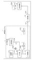
- FIG. 5 is a block diagram showing a detailed configuration example of the signal transmission system of FIG. 1 in an example in which the intermediate frequency / heterodyne method is adopted.
- the signal transmission system 1 of the example of FIG. 5 is the signal transmission system 1 of the example of FIG. 1, and further includes a local oscillation unit 131, a mixer unit 132, a laser generation unit 133, an optical combine unit 134, and a signal path LL21. To LL26.
- the functions and configurations of the Y-00 encryption output unit 111 in the example of FIG. 5 are basically the same as the functions and configurations of the Y-00 encryption output unit 111 in the example of FIG. 4, their description is omitted here. To do. That is, the frequencies included in the first electric signal have, for example, the distribution shown in the graph FE21, which is basically the same as the distribution shown in the graph FE11 in the example of FIG. 4, and thus the description thereof will be omitted here.
- the first electric signal output by the Y-00 encryption output unit 111 is transmitted to the mixer unit 132 via the signal path LL21.
- the local oscillation unit 131 oscillates a local oscillation signal corresponding to the intermediate frequency fIF described later.
- the local oscillation signal oscillated by the local oscillation unit 131 is transmitted to the mixer unit 132 via the signal path LL22.
- the intermediate frequency electric signal is transmitted to the E / O conversion unit 112 via the signal path LL23.
- the mixer unit 132 has a configuration according to the modulation method, and outputs an intermediate frequency electric signal from the first electric signal and the local oscillation signal. That is, the specific configuration of the mixer unit 132 may be configured according to a modulation method such as intensity modulation, amplitude modulation, phase modulation, frequency modulation, or orthogonal amplitude modulation.
- the frequencies included in the intermediate frequency electric signal output from the mixer unit 132 have, for example, the distribution shown in the graph FE22.
- the frequencies included in the optical signal have, for example, the distribution shown in the graph FO21, which is basically the same as the distribution shown in the graph FO11 in the example of FIG. 4, and thus the description thereof will be omitted here.
- the optical signal output by the E / O conversion unit 112 is transmitted to the optical combine unit 134 via the signal path LL 24 configured by an optical fiber or the like.
- the carrier light of the example of FIG. 4 is transmitted to the optical combine unit 134 via the signal path LL25 configured by an optical fiber or the like.
- the frequencies included in the carrier light generated from the laser generation unit 133 have the distribution shown in the graph FO23, for example.
- the optical combine unit 134 combines the optical signal and the carrier light. That is, it outputs a combined optical signal that combines both the optical signal transmitted via the signal path LL24 and the carrier light transmitted via the signal path LL25.
- the combined optical signal of the example of FIG. 5 is transmitted to the O / E conversion unit 13 via the signal path LL26 configured by an optical fiber or the like.
- the optical combine unit 134 may be configured by an optical power combiner, an optical wavelength division multiplexing device, or the like.
- the frequencies included in the combined optical signal output from the optical combine unit 134 have, for example, the distribution shown in the graph FO23.
- the O / E conversion unit 13 converts the combined optical signal into a second electric signal.
- the center frequency of the second electric signal is the frequency obtained by adding fIF.
- the functions and configurations of the radio wave transmitting unit 14 and the signal path LE 12 are basically the same as the functions and configurations of the radio wave transmitting unit 14 and the signal path LE 12 in FIG. The description is omitted. Further, the frequencies included in the second electric signal transmitted by the signal path LE12 are, for example, the distribution shown in the graph FE23, which is basically the same as the distribution shown in the graph FE12 in the example of FIG. The description is omitted. As a result, the radio wave transmission unit 14 transmits the encrypted signal of the second electric signal in the form of radio wave RW.
- an optical transmission medium such as an optical fiber and a component that operates a signal in an optical region such as an optical filter and an optical amplifier may be inserted as needed.
- components such as a filter and an amplifier in the fRF frequency band are provided in addition to a transmission medium such as an RF transmission cable, as in the example of FIG. It may be inserted as needed.
- the E / O converter 112 By converting to an intermediate frequency electric signal, the E / O converter 112 is relatively simple, such as a combination of a laser and a light intensity modulator (Machzenda modulator or electric field absorption type modulator) or direct modulation of the laser. It can be configured as such. That is, it is relatively simpler for the E / O conversion unit 112 to convert an intermediate frequency electric signal into an optical signal as compared with the case where the first electric signal generated in the baseband is converted into an optical signal. That is, it can be converted by a relatively inexpensive configuration.
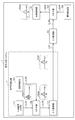
- FIG. 6 is a block diagram showing a detailed configuration example of the signal transmission system of FIG. 1 in which the analog / direct modulation method is adopted.
- the signal transmission system 1 of the example of FIG. 6 further includes a local oscillation unit 141, a mixer unit 142, and signal paths LL31 to LL33 in addition to the signal transmission system 1 of the example of FIG.
- the functions and configurations of the Y-00 encryption output unit 111 in the example of FIG. 6 are basically the same as the functions and configurations of the Y-00 encryption output unit 111 in the example of FIG. 4, their description is omitted here. To do. That is, the frequencies included in the first electric signal have, for example, the distribution shown in the graph FE31, which is basically the same as the distribution shown in the graph FE11 in the example of FIG. 4, and thus the description thereof will be omitted here.
- the first electric signal output by the Y-00 encryption output unit 111 is transmitted to the mixer unit 142 via the signal path LL31.
- the local oscillation unit 141 oscillates a local oscillation signal corresponding to the intermediate frequency fRF described later. That is, the local oscillation unit 141 of the example of FIG. 6 oscillates a local oscillation signal corresponding to fRF, which is the frequency of the radio wave RW, as an intermediate frequency.
- the local oscillation signal oscillated by the local oscillation unit 141 is transmitted to the mixer unit 142 via the signal path LL32.
- the intermediate frequency electric signal is transmitted to the E / O conversion unit 112 via the signal path LL33.
- the mixer unit 142 can be configured according to the modulation method, but since it is basically the same as the configuration example of the mixer unit 132 in the example of FIG. 5, their description is omitted here.
- the frequencies included in the intermediate frequency electric signal output from the mixer unit 142 have, for example, the distribution shown in the graph FE32.
- the frequencies included in the optical signal have, for example, the distribution shown in the graph FO3, which is basically the same as the distribution shown in the graph FO11 in the example of FIG. 4, and thus the description thereof will be omitted here.
- the optical signal output by the E / O conversion unit 112 is transmitted to the O / E conversion unit 13 via a signal path LO1 configured by an optical fiber or the like.
- the O / E conversion unit 13 converts an optical signal into a second electric signal.
- the functions and configurations of the radio wave transmitting unit 14 and the signal path LE 12 are basically the same as the functions and configurations of the radio wave transmitting unit 14 and the signal path LE 12 in FIG. The description is omitted.
- the frequencies included in the second electric signal transmitted by the signal path LE12 are, for example, the distribution shown in the graph FE33, which is basically the same as the distribution shown in the graph FE12 in the example of FIG. The description is omitted.
- the radio wave transmission unit 14 transmits the encrypted signal of the second electric signal in the form of radio wave RW.
- a signal is transmitted between the E / O conversion unit 112 and the O / E conversion unit 13 in an optical transmission medium such as an optical fiber or an optical region such as an optical filter or an optical amplifier, as in the example of FIG.
- Components that operate on may be inserted as needed.
- components such as a filter and an amplifier in the fRF frequency band are provided in addition to a transmission medium such as an RF transmission cable, as in the example of FIG. It may be inserted as needed.
- the E / O converter 112 By converting to an intermediate frequency electric signal, the E / O converter 112 is relatively simple, such as a combination of a laser and a light intensity modulator (Machzenda modulator or electric field absorption type modulator) or direct modulation of the laser. It can be configured as such. That is, it is relatively simpler for the E / O conversion unit 112 to convert an intermediate frequency electric signal into an optical signal as compared with the case where the first electric signal generated in the baseband is converted into an optical signal. That is, it can be converted by a relatively inexpensive configuration.
- FIG. 7 is a block diagram showing a detailed configuration example of the signal transmission system of FIG. 1 in which the analog / intermediate frequency method is adopted.
- the signal transmission system 1 of the example of FIG. 7 is the signal transmission system 1 of the example of FIG. 1, and further includes a local oscillation unit 151, a mixer unit 152, a local oscillation unit 153, a mixer unit 154, and a signal path LL41 to It is equipped with LL46.
- the functions and configurations of the Y-00 encryption output unit 111 in the example of FIG. 7 are basically the same as the functions and configurations of the Y-00 encryption output unit 111 in the example of FIG. 4, their description is omitted here.
- the frequencies included in the first electric signal have, for example, the distribution shown in the graph FE41, which is basically the same as the distribution shown in the graph FE11 in the example of FIG. 4, and thus the description thereof will be omitted here.
- the first electric signal output by the Y-00 encryption output unit 111 is transmitted to the mixer unit 152 via the signal path LL41.
- the functions and configurations of the local oscillator 151 and the mixer 152 in the example of FIG. 7 are basically the same as those of the functions and configurations of the local oscillator 131 and the mixer 132 in the example of FIG. Since there are some, their explanations are omitted here. That is, the frequencies included in the first electric signal and the intermediate frequency electric signal are, for example, the distributions shown in the graph FE41 and the graph FE42, respectively, and the distributions shown in the graph FE21 and the graph FE22 in the example of FIG. Since they are basically the same, their description is omitted here.
- the intermediate frequency electric signal is transmitted to the E / O conversion unit 112 via the signal path LL43.
- the local oscillation signal oscillated by the local oscillation unit 151 is hereinafter referred to as a “first local oscillation signal” in order to clearly distinguish it from the second local oscillation signal described later.
- the frequencies included in the optical signal have, for example, the distribution shown in the graph FO4, which is basically the same as the distribution shown in the graph FO11 in the example of FIG. 4, and thus the description thereof will be omitted here.
- the optical signal output by the E / O conversion unit 112 is transmitted to the O / E conversion unit 13 via a signal path LO1 configured by an optical fiber or the like.
- the O / E conversion unit 13 converts an optical signal into a second electric signal.
- the second electric signal output by the O / E conversion unit 13 is transmitted to the mixer unit 154 via the signal path LL44.
- the second local oscillation signal oscillated by the local oscillation unit 153 is transmitted to the mixer unit 154 via the signal path LL45.
- the mixer unit 154 can be configured according to the modulation method, but since it is basically the same as the configuration example of the mixer unit 132 in the example of FIG. 5, their description is omitted here.
- the frequencies included in the mixed electric signals output from the mixer unit 154 are, for example, the distribution shown in the graph FE43, which is basically the same as the distribution shown in the graph FE12 in the example of FIG. The description is omitted.
- the radio wave transmission unit 14 transmits the encrypted signal of the mixed electric signal in the form of the radio wave RW.
- an optical transmission medium such as an optical fiber and a component that operates a signal in an optical region such as an optical filter and an optical amplifier may be inserted as needed.
- components such as a filter and an amplifier in the fRF frequency band are provided in addition to a transmission medium such as an RF transmission cable, as in the example of FIG. It may be inserted as needed.
- a signal is transmitted between the E / O conversion unit 112 and the O / E conversion unit 13 in an optical transmission medium such as an optical fiber or an optical region such as an optical filter or an optical amplifier, as in the example of FIG.
- Components that operate on may be inserted as needed.
- the space between the O / E conversion unit 13 and the mixer unit 154 and between the mixer unit 154 and the radio wave transmission unit 14 in addition to the transmission medium such as the RF transmission cable, as in the example of FIG. Therefore, components such as filters and amplifiers in the frequency band of fRF may be inserted as needed.
- FIG. 8 is a block diagram showing a detailed configuration example of the signal transmission system of FIG. 1 in which the analog baseband method is adopted.
- the signal transmission system 1 of the example of FIG. 8 further includes a local oscillation unit 161 and a mixer unit 162, and signal paths LL51 to LL53, in addition to the signal transmission system 1 of the example of FIG.
- the functions and configurations of the Y-00 encryption output unit 111 of the example of FIG. 8 are basically the same as the functions and configurations of the Y-00 encryption output unit 111 of the example of FIG. 4, their description is omitted here. To do. That is, the frequencies included in the first electric signal have, for example, the distribution shown in the graph FE51, which is basically the same as the distribution shown in the graph FE11 in the example of FIG. 4, and thus the description thereof will be omitted here.
- the first electric signal output by the Y-00 encryption output unit 111 is transmitted to the E / O conversion unit 112 via the signal path LE11.
- the functions and configurations of the E / O conversion unit 112 of the example of FIG. 8 are basically the same as the functions and configurations of the E / O conversion unit 112 of the example of FIG. 4, their description will be omitted here. That is, the frequencies included in the optical signal have, for example, the distribution shown in the graph FO5, which is basically the same as the distribution shown in the graph FO11 in the example of FIG. 4, and thus the description thereof will be omitted here.
- the optical signal converted by the E / O conversion unit 112 is transmitted to the O / E conversion unit 13 via the signal path LO1 configured by an optical fiber or the like.
- the O / E conversion unit 13 converts an optical signal into a second electric signal.
- the second electric signal converted by the O / E conversion unit 13 is transmitted to the mixer unit 162 via the signal path LL51.
- the local oscillation unit 161 oscillates a local oscillation signal corresponding to the intermediate frequency fRF. That is, the local oscillation unit 161 in the example of FIG. 8 oscillates a local oscillation signal corresponding to fRF, which is the frequency of the radio wave RW, as an intermediate frequency.
- the local oscillation signal oscillated by the local oscillation unit 161 is transmitted to the mixer unit 162 via the signal path LL 52.
- the added center frequency f0 fRF. That is, the frequency of the radio wave RW to be transmitted is output as an electric signal mixed by the mixer unit 162.
- the mixed electric signal is transmitted to the radio wave transmission unit 14 via the signal path LL53.
- the mixer unit 162 can be configured according to the modulation method, but since it is basically the same as the configuration example of the mixer unit 132 in the example of FIG. 5, their description is omitted here.
- the frequencies included in the mixed electric signals output from the mixer unit 162 are, for example, the distribution shown in the graph FE52, which is basically the same as the distribution shown in the graph FE12 in the example of FIG. The description is omitted.
- the radio wave transmission unit 14 transmits the encrypted signal of the mixed electric signal in the form of the radio wave RW.
- a signal is transmitted between the E / O conversion unit 112 and the O / E conversion unit 13 in an optical transmission medium such as an optical fiber or an optical region such as an optical filter or an optical amplifier, as in the example of FIG.
- Components that operate on may be inserted as needed.
- the space between the O / E conversion unit 13 and the mixer unit 154 and between the mixer unit 154 and the radio wave transmission unit 14 in addition to the transmission medium such as the RF transmission cable, as in the example of FIG. Therefore, components such as filters and amplifiers in the frequency band of fRF may be inserted as needed.
- the signal transmission system 1 to which the present invention is applied has been described above.
- the signal transmission system 1 to which the present invention is applied is sufficient as long as it can output an electric signal having a large noise masking amount ⁇ in the form of a radio wave RW, and its configuration is limited to the above-mentioned various embodiments.
- it may be as follows.
- the signal transmission system 1 encrypts the signal to be transmitted and transmits it in the form of a radio wave RW, and the signal reception system 2 receives and decodes the radio wave RW. Therefore, the signal of the above-described form is received, but the present invention is not particularly limited to this.
- the signal processing system may have both a configuration related to transmission of radio wave RW and a configuration related to reception of radio wave RW, and may be capable of transmitting and receiving encrypted signals in the form of radio wave RW.
- the signal transmission / reception system is composed of the signal transmission system 1 and the signal reception system 2, but is not particularly limited thereto.
- a configuration may include a plurality of signal processing systems capable of transmitting and receiving encrypted signals in the form of radio wave RW.
- the signal processing system can form a network.
- the Y-00 encryption output unit 111 of the optical signal generation unit 11 uses the predetermined data to be transmitted as multi-valued information based on the Y-00 optical communication quantum cryptography protocol.
- multi-valued information is generated from the predetermined data to be transmitted and the private key based on the Y-00 optical communication quantum cryptography protocol, but the present invention is not particularly limited to this.
- the optical signal generation unit 11 may generate multi-valued information from predetermined data to be transmitted and a predetermined common key.
- multi-valued information may be generated from predetermined data to be transmitted and predetermined rules. That is, it suffices if the optical signal generation unit 11 can generate multi-valued information based on an arbitrary protocol.
- the noise masking amount ⁇ is "the number of symbol points within the range of the standard deviation when the distribution of shot noise is approximated as a Gaussian distribution", but the present invention is particularly limited to this. Not done. That is, the noise masking amount ⁇ is sufficient if it is the number of symbol points within an arbitrary noise range. Specifically, for example, the noise in the noise masking amount ⁇ may include any noise including classical noise such as thermal noise. Further, the range of the noise masking amount ⁇ is not limited to the range of the standard deviation when the noise distribution is approximated as a Gaussian distribution. Specifically, for example, the distribution obtained by actually measuring the noise may be acquired, and the variance of the acquired distribution may be used as the range. That is, the noise masking amount ⁇ is not limited to the above-mentioned equation (1), which is an equation when the phase modulation method is adopted.
- the distance between two adjacent symbol points is sufficiently smaller than the range of all noise including classical noise such as thermal noise. That is, for the optical signal generated by the optical signal generation unit 11, it is sufficient that the amount of noise masking by all "noise” including classical noise such as thermal noise is 1 or more.
- FIGS. 4 to 8 are used to illustrate a block showing a detailed configuration example in an example in which various methods are adopted in the signal transmission system 1, but the present invention is not particularly limited thereto.
- signal processing may be performed by providing a plurality of intermediate frequencies as intermediate frequencies.
- combining the laser beam by the optical combine unit and acquiring the beat component may be repeated a plurality of times. That is, the signal transmission system 1 can be configured to include an arbitrary number of mixer units and optical combine units.
- the signal path for transmitting the optical signals of FIGS. 1 and 3 to 8 (for example, the signal path LO1A of FIG. 1) is composed of an optical signal path by an optical communication cable.
- the signal path for transmitting the optical signal may be a path that propagates (transmits) the optical signal.
- a signal path spatial propagation that propagates an optical signal in the atmosphere or a vacuum can be adopted.
- the optical signal is converted by using the optical signal amplification unit 12 of FIG. 1 and the optical combine unit 122 of FIG. 4, but the present invention is not particularly limited to this. That is, as the type of conversion of the optical signal, various types of conversion can be adopted. For example, it may be amplification of an optical signal, branching of an optical signal, switching of an optical signal (switching of a path), extension of a transmission path of an optical signal, or combination of an optical signal.
- the signal processing device to which the present invention is applied is sufficient as long as it is as follows, and various various embodiments can be taken. That is, the signal processing system to which the present invention is applied (for example, the signal transmission system 1 in FIG. 1) is Optical generation that generates multi-valued information (multi-valued information generated based on the Y-00 optical communication quantum cryptography protocol) that takes a multi-valued state based on predetermined data (for example, predetermined data to be transmitted) as an optical signal.
- Means for example, the optical signal generation unit 11 in FIG. 1
- Photoelectric conversion means for example, O / E conversion unit 13 in FIG.
- a radio wave transmitting means for example, a radio wave transmitting unit 14 in FIG. 1 that transmits the multi-valued information converted into the electric signal as a radio wave (for example, the radio wave RW in FIG. 1).
- a signal processing system equipped with the above is sufficient.
- the light generating means is The multi-value information generating means (for example, the Y-00 encryption output unit 111 in FIG. 1) that generates the first electric signal of the multi-value information, An electro-optical conversion means for converting the first electric signal of the multi-valued information into an optical signal (for example, the E / O conversion unit 112 in FIG. 1) and Have, The photoelectric conversion means converts the optical signal into a second electric signal different from the first electric signal. be able to.
- the multi-value information generating means for example, the Y-00 encryption output unit 111 in FIG. 1
- An electro-optical conversion means for converting the first electric signal of the multi-valued information into an optical signal for example, the E / O conversion unit 112 in FIG. 1 and Have
- the photoelectric conversion means converts the optical signal into a second electric signal different from the first electric signal. be able to.
- multi-valued information based on predetermined data can be generated in the form of an electric signal. Further, the multi-valued information based on the predetermined data is converted from the form of the electric signal to the form of the optical signal.
- an optical conversion means for converting (for example, amplifying, branching, switching, extending, combining) the optical signal (for example, the optical signal amplification unit 12 in FIG. 1 and the optical combine unit 122 in FIG. 4).
- the photoelectric conversion means converts the optical signal converted by the optical conversion means. be able to.
- the noise of the optical signal increases due to various conversions (amplification and combine).
- an optical signal with increased noise is converted into an electric signal, the difficulty of correctly constructing data from the electric signal increases, and the effect of measures against eavesdropping at the physical layer is improved.
- the optical conversion means converts the optical signal into an optical signal containing components having different frequencies as compared with the optical signal.
- the photoelectric conversion means converts the optical signal converted by the optical conversion means into an electric signal that does not contain a component having a higher frequency than the optical signal. be able to.
- an optical signal is converted into an optical signal containing different components, and an optical signal containing components having different frequencies is converted into a second electric signal.
- an electric signal including a frequency component which is a beat component is generated.
- the beat component is basically a low frequency component as compared to the original frequency component.
- the higher the frequency of the optical signal the more effective the countermeasure against eavesdropping in the physical layer is. That is, in such a signal processing system, the optical signal having a higher frequency is used. The effect of measures against eavesdropping in the physical layer is improved, and it can be transmitted as a radio wave having a frequency lower than that of an optical signal.
- a second electric signal conversion means (for example, the local oscillator unit 153 and the mixer unit 154 in FIG. 7) that converts the second electric signal into an electric signal having a frequency different from that of the second electric signal.
- the radio wave transmitting means transmits the second electric signal converted by the second electric signal converting means as a radio wave. be able to.
- Such a signal processing system can convert the frequency of the second electric signal obtained by converting the optical signal into the frequency transmitted as radio waves. That is, the signal processing system generates noise at the frequency of the optical signal, so that the effect of measures against eavesdropping in the physical layer is improved by the optical signal, and the signal can be transmitted as a radio wave.
Landscapes
- Physics & Mathematics (AREA)
- Engineering & Computer Science (AREA)
- Computer Networks & Wireless Communication (AREA)
- Signal Processing (AREA)
- Electromagnetism (AREA)
- Optics & Photonics (AREA)
- Optical Communication System (AREA)
Abstract
無線通信における物理層での盗聴の対策を行う信号処理を提供することを課題とする。 光信号発生部11は、所定データに基づく多値の状態をとる多値情報を、光信号として発生させる。E/O変換部112は、前記光信号を、電気信号に変換する。光信号増幅部12は、前記光信号を、増幅する。O/E変換部13は、前記光信号を、電気信号に変換する。電波送信部14は、前記電気信号に変換された前記多値情報を、電波として送信する。これにより、上記課題を解決する。
Description
本発明は、信号処理システムに関する。
近年、情報通信においてセキュリティ対策の重要性が高まっている。インターネットを構成するネットワークシステムは、国際標準化機構に依り策定されたOSI参照モデルで記述される。OSI参照モデルでは、レイヤ1の物理層からレイヤ7のアプリケーション層までに分離され、夫々のレイヤを結ぶインターフェースが標準化、又は、デファクトにより規格化されている。このうち最下層となるのが、有線・無線で実際に信号の送受信を行う役割を担う物理層である。
現状、セキュリティ(多くの場合数理暗号に依る)は、レイヤ2以上で実装されており、物理層ではセキュリティ対策が施されていない。しかしながら、物理層でも盗聴の危険性がある。
例えば、有線通信の代表である光ファイバ通信では、光ファイバに分岐を導入し、信号パワーの一部を取り出すことで大量の情報を一度に盗み出すことが原理的に可能である。そこで、本出願人は、物理層における暗号化技術として、例えば特許文献1に挙げる所定のプロトコルの開発を行っている。
現状、セキュリティ(多くの場合数理暗号に依る)は、レイヤ2以上で実装されており、物理層ではセキュリティ対策が施されていない。しかしながら、物理層でも盗聴の危険性がある。
例えば、有線通信の代表である光ファイバ通信では、光ファイバに分岐を導入し、信号パワーの一部を取り出すことで大量の情報を一度に盗み出すことが原理的に可能である。そこで、本出願人は、物理層における暗号化技術として、例えば特許文献1に挙げる所定のプロトコルの開発を行っている。
しかしながら、上述の特許文献1を含む従来技術では、多値の情報を光信号として送信することにより、光ファイバを用いた物理層での盗聴の対策を行うことはできるが、無線通信における物理層での盗聴の対策を行うことはできなかった。
本発明は、無線通信における物理層での盗聴の対策を行うことを目的とする。
上記目的を達成するため、本発明の一態様の信号処理システムは、
所定データに基づく多値の状態をとる多値情報を、光信号として発生させる光発生手段と、
前記光信号を、電気信号に変換する光電気変換手段と、
前記電気信号に変換された前記多値情報を、電波として送信する電波送信手段と、
を備える。
所定データに基づく多値の状態をとる多値情報を、光信号として発生させる光発生手段と、
前記光信号を、電気信号に変換する光電気変換手段と、
前記電気信号に変換された前記多値情報を、電波として送信する電波送信手段と、
を備える。
本発明によれば、無線通信における物理層での盗聴の対策を行うことができる。
以下、本発明の実施形態について説明する。
図1は、本発明の信号処理システムの一実施形態に係る信号送受信システムの構成の一例を示すブロック図である。
図1の例の信号送受信システムは、信号送信システム1と、信号受信システム2とを含むように構成されている。
信号送信システム1は、送信対象の信号を、Y-00光通信量子暗号のプロトコルに基づき暗号化して、電波RWの形態で送信する。また、信号受信システム2は、この電波RWを受信して、Y-00光通信量子暗号のプロトコルに基づき復号して、上述の形態の信号を受信する。
なお、詳細は後述するが、Y-00光通信量子暗号とは、Y-00光通信量子暗号のプロトコルに基づいて、送信対象である所定データを多値の情報とした後、光信号として送信することにより、受信した信号は暗号化された暗号信号となるという原理に基づいた暗号方式である。
まず、Y-00光通信量子暗号のプロトコルに基づき暗号化した電波RWを送信する信号送信システム1の構成について説明する。
信号送信システム1は、光信号発生部11と、光信号増幅部12と、O/E変換部13と、電波送信部14とを含むように構成されている。
信号送信システム1は、光信号発生部11と、光信号増幅部12と、O/E変換部13と、電波送信部14とを含むように構成されている。
光信号発生部11は、所定データに基づく多値の状態をとる多値情報を、光信号として発生させる。この光信号は、その詳細については後述するが、送信対象の信号である。
光信号発生部11は、Y-00暗号出力部111と、E/O変換部112とを備える。
光信号発生部11は、Y-00暗号出力部111と、E/O変換部112とを備える。
Y-00暗号出力部111は、所定データに基づく多値の状態をとる多値情報の電気信号(後述の第2乃至第4電気信号と明確に区別すべく、以下、「第1電気信号」と呼ぶ)を発生する。
即ち、Y-00暗号出力部111は、送信対象である所定データを生成し又は図示せぬ生成元から取得する。Y-00暗号出力部111は、この所定データを用いて、Y-00光通信量子暗号のプロトコルに基づき生成した多値の情報を、多値情報として第1電気信号の形態で信号路LE11を介して出力する。
なお、信号路LE11における第1電気信号は、アナログ信号、及びデジタル信号の何れでも良いが、本実施形態の説明においては、アナログ信号であるものとして説明する。なお、第1電気信号がデジタル信号である場合、信号路LE11は、複数のビットを送信できる構成(例えば、パラレルに信号を送信する複数の信号路や、シリアルに信号を送信するデータ処理部からなる構成)を適宜備える。
E/O変換部112は、Y-00暗号出力部111から出力された多値情報の第1電気信号を、光信号に変換する。
即ち、E/O変換部112は、LE11を介して入力した、多値情報の第1電気信号を、任意の変調方式により変調された光信号に変換して信号路LO1Aを介して出力する。
即ち、E/O変換部112は、LE11を介して入力した、多値情報の第1電気信号を、任意の変調方式により変調された光信号に変換して信号路LO1Aを介して出力する。
なお、信号路LO1Aは、光通信ケーブルによる光信号路で構成されてよい。
このように信号路LO1Aとして光通信ケーブルを用いることにより、信号送信システム1において、E/O変換部112と、後述するO/E変換部13とは、距離を離して設置することができる。
このように信号路LO1Aとして光通信ケーブルを用いることにより、信号送信システム1において、E/O変換部112と、後述するO/E変換部13とは、距離を離して設置することができる。
光信号増幅部12は、E/O変換部112から発生された光信号を増幅する。
即ち、光信号増幅部12は、E/O変換部から発生されて信号路LO1Aにより伝送されてきた光信号を増幅して出力する。光信号増幅部12から出力された光信号(増幅された光信号)は、信号路LO1Bを介してO/E変換部13に伝送される。
即ち、光信号増幅部12は、E/O変換部から発生されて信号路LO1Aにより伝送されてきた光信号を増幅して出力する。光信号増幅部12から出力された光信号(増幅された光信号)は、信号路LO1Bを介してO/E変換部13に伝送される。
なお、信号路LO1Bは、信号路LO1Aと同様に、光通信ケーブルによる光信号路で構成されてよい。つまり、光信号増幅部12は、信号路LO1Aを通ることによって減衰した光信号を増幅することが可能な、光信号路における中継器として用いることができる。このような中継器たる光信号増幅部12を採用することで、E/O変換部112と、後述するO/E変換部13との間の光信号路の距離を延長させることができる。換言すると、E/O変換部112と、後述するO/E変換部13とは、更に距離を離して設置することができる。
O/E変換部13は、光信号増幅部12で増幅されて信号路LOBにより伝送されてきた光信号を、電気信号(上述の第1電気信号や後述の第3及び第4電気信号と明確に区別すべく、以下、「第2電気信号」と呼ぶ)に変換する。
即ち、O/E変換部13は、Y-00光通信量子暗号のプロトコルに基づき生成された多値情報に対応した光信号であって、信号路LO1により伝送されてきた光信号を、第2電気信号に変換して出力する。
O/E変換部13から出力された第2電気信号は、信号路LE12を介して電波送信部14に伝送される。
第2電気信号は、O/E変換部13により光信号から変換された結果、ショット雑音を含んだ電気信号となる。即ち、後述するY-00光通信量子暗号の原理により、暗号化された信号(以下、「暗号信号」と呼ぶ)となる。暗号信号は、Y-00光通信量子暗号のプロトコルにおける復号を経ない限り、データを正しく再構築できない。即ち、第2電気信号は、第三者により傍受されたとしても、第三者は解読困難である。
なお、本明細書において、暗号信号の用語は、電気信号や光信号、電波等の形態によらず、暗号化された信号のことを指す。
なお、図1において、光信号増幅部12は破線で示されている。これは、信号送信システム1にとって、光信号増幅部12は必須な構成要素ではなく、仮に光信号増幅部12を構成要素に含めた場合であってもその個数は1個に限定されず任意の個数でよいことを意味している。
即ち、E/O変換部112とO/E変換部13との間の光伝送路の距離が長くなった場合等には、当該光伝送路内の中継部たる光信号増幅部12は、複数個導入することができる。
これに対して、E/O変換部112とO/E変換部13との間の光伝送路の距離が短くなった場合等であって、E/O変換部112から発生された光信号を増幅する必要がない場合、信号送信システム1は、光信号増幅部12を含まない構成とすることができる。
以降、特別に記述しない限り、信号送信システム1は、光信号増幅部12を含まず構成されており、E/O変換部112と、O/E変換部13とは、直接接続された信号路LO1A及び信号路LO1B(以下、これらをまとめて「信号路LO1」と呼ぶ)を介して接続されているものとする。
電波送信部14は、O/E変換部13により第2電気信号に変換されて信号路LE12により伝送されてきた暗号信号を、電波RWの形態で送信する。
即ち、電波送信部14は、暗号信号である第2電気信号を、所定の増幅や周波数の変換等の制御を施したうえで、アンテナ等の部品を介して、電波RWとして送信する。
即ち、電波RWの形態で送信された第2電気信号は、暗号信号である。
即ち、電波送信部14は、暗号信号である第2電気信号を、所定の増幅や周波数の変換等の制御を施したうえで、アンテナ等の部品を介して、電波RWとして送信する。
即ち、電波RWの形態で送信された第2電気信号は、暗号信号である。
ここで、第三者が、電波RWを傍受し、電気信号に変換した場合を考える。この場合、第三者により取得された電波RWの電気信号は、Y-00光通信量子暗号のプロトコルに基づき生成された多値の情報を光信号に変換し、更に、光信号を第2電気信号に変換した、暗号信号である。即ち、第三者により取得された電波RWの電気信号を解読することは、困難である。
以上、Y-00光通信量子暗号のプロトコルに基づき暗号化した暗号信号を電波RWの形態で送信する信号送信システム1の構成例について説明した。
次に、電波RWを受信してY-00光通信量子暗号のプロトコルに基づき復号する信号受信システム2の構成例について説明する。
次に、電波RWを受信してY-00光通信量子暗号のプロトコルに基づき復号する信号受信システム2の構成例について説明する。
信号受信システム2は、電波受信部21と、E/O変換部22と、光信号増幅部23と、O/E変換部24と、Y-00暗号入力部25とを含むように構成されている。
電波受信部21は、信号送信システム1により送信された電波RWを受信する。
即ち、電波受信部21は、電波RWの形態の暗号信号をアンテナ等で受信し、電気信号(上述の第1及び第2電気信号や後述の第4電気信号と明確に区別すべく、以下、「第3電気信号」と呼ぶ)の形態で出力する。電波受信部21から出力された第3電気信号は、信号路LE21を介して、E/O変換部22に伝送される。
即ち、電波受信部21は、電波RWの形態の暗号信号をアンテナ等で受信し、電気信号(上述の第1及び第2電気信号や後述の第4電気信号と明確に区別すべく、以下、「第3電気信号」と呼ぶ)の形態で出力する。電波受信部21から出力された第3電気信号は、信号路LE21を介して、E/O変換部22に伝送される。
E/O変換部22は、電波受信部21で受信された電波RWに対応する第3電気信号を、光信号に変換する。
即ち、E/O変換部22は、電波受信部21で受信されて信号路LE21により伝送された第3電気信号の形態の暗号信号を、光信号の形態に変換して出力する。E/O変換部22から出力された第3電気信号は、信号路LO2Aを介して光信号増幅部23に伝送される。
即ち、E/O変換部22は、電波受信部21で受信されて信号路LE21により伝送された第3電気信号の形態の暗号信号を、光信号の形態に変換して出力する。E/O変換部22から出力された第3電気信号は、信号路LO2Aを介して光信号増幅部23に伝送される。
なお、信号路LO2Aは、光通信ケーブルによる光信号路で構成されてよい。
このように信号路LO2Aとして光通信ケーブルを用いることにより、信号受信システム2において、E/O変換部22と、後述するO/E変換部24とは、距離を離して設置することができる。
このように信号路LO2Aとして光通信ケーブルを用いることにより、信号受信システム2において、E/O変換部22と、後述するO/E変換部24とは、距離を離して設置することができる。
光信号増幅部23は、E/O変換部22で変換された光信号を増幅する。
即ち、光信号増幅部23は、E/O変換部で変換されて信号路LO2Aにより伝送されてきた光信号を増幅して出力する。光信号増幅部23から出力された光信号(増幅された光信号)は、信号路LO2Bを介してO/E変換部24に伝送される。
即ち、光信号増幅部23は、E/O変換部で変換されて信号路LO2Aにより伝送されてきた光信号を増幅して出力する。光信号増幅部23から出力された光信号(増幅された光信号)は、信号路LO2Bを介してO/E変換部24に伝送される。
なお、信号路LO2Bは、信号路LO2Aと同様に、光通信ケーブルによる光信号路で構成されてよい。
つまり、光信号増幅部23は、信号路LO2Aを通ることによって減衰した光信号を増幅することが可能な、光信号路における中継器として用いることができる。このような中継器たる光信号増幅部23を採用することで、E/O変換部22と、後述するO/E変換部24との間の光信号路の距離を延長させることができる。換言すると、E/O変換部22と、後述するO/E変換部24とは、更に距離を離して設置することができる。
つまり、光信号増幅部23は、信号路LO2Aを通ることによって減衰した光信号を増幅することが可能な、光信号路における中継器として用いることができる。このような中継器たる光信号増幅部23を採用することで、E/O変換部22と、後述するO/E変換部24との間の光信号路の距離を延長させることができる。換言すると、E/O変換部22と、後述するO/E変換部24とは、更に距離を離して設置することができる。
なお、図1において、光信号増幅部23は破線で示されている。これは、信号受信システム2にとって、光信号増幅部23は必須な構成要素ではなく、仮に光信号増幅部23を構成要素に含めた場合であってもその個数は1個に限定されず任意の個数でよいことを意味している。
即ち、E/O変換部22とO/E変換部24との間の光伝送路の距離が長くなった場合等には、当該光伝送路内の中継部たる光信号増幅部23は、複数個導入することができる。
これに対して、E/O変換部22とO/E変換部24との間の光伝送路の距離が短くなった場合等であって、E/O変換部22から発生された光信号を増幅する必要がない場合、信号受信システム2は、光信号増幅部23を含まない構成とすることができる。
以降、特別に記述しない限り、信号受信システム2は、光信号増幅部23を含まず構成されており、E/O変換部22と、O/E変換部24とは、直接接続された信号路LO2A及び信号路LO2B(以下、これらをまとめて「信号路LO2」と呼ぶ)を介して接続されているものとする。
O/E変換部24は、光信号増幅部12で増幅されて信号路LO2により伝送されてきた光信号を、電気信号(上述の第1乃至第3電気信号と明確に区別すべく、以下、「第4電気信号」と呼ぶ)に変換する。
即ち、O/E変換部24は、電波RWの暗号信号に対応した光信号であって、信号路LO2からなる光伝送路により伝送されてきた光信号を、第4電気信号に変換して出力する。
O/E変換部24から出力された第4電気信号は、信号路LE22を介してY-00暗号入力部25に伝送される。
即ち、O/E変換部24は、電波RWの暗号信号に対応した光信号であって、信号路LO2からなる光伝送路により伝送されてきた光信号を、第4電気信号に変換して出力する。
O/E変換部24から出力された第4電気信号は、信号路LE22を介してY-00暗号入力部25に伝送される。
Y-00暗号入力部25は、O/E変換部24で変換された第4電気信号の形態の暗号信号を信号路LE22を介して入力され、Y-00光通信量子暗号のプロトコルに基づき、復号することで、送信対象であった所定データに変換する。また、Y-00暗号入力部25は、復号された所定データを取得又は図示せぬ受信先に提供する。
また、さらに言えば、電波受信部21と、Y-00暗号入力部25を近くに設置する場合、電波受信部21と、Y-00暗号入力部25とは、直接接続された信号路LE21及び信号路LE22を介して接続されてよい。即ち、第3電気信号を、直接、第4電気信号として採用してY-00暗号入力部25に入力することができる。
以上、信号受信システム2が、電波RWを受信してY-00光通信量子暗号のプロトコルに基づき復号する信号受信システム2の構成例について説明した。
このように、本実施形態の信号送受信システムでは、E/O変換部112とO/E変換部13とが、信号路LO1により光信号を伝送するものとして採用されている。このため、図1の例では、光信号の通信方式として、有線通信の代表である光ファイバ通信が採用されている。
光ファイバ通信では、第三者が、光ファイバに分岐を導入し、信号パワーの一部を取り出すことで、大量の情報(ここでは暗号化された信号。以下、「暗号信号」と呼ぶ)を一度に盗み出すことが原理的に可能である。
光ファイバ通信では、第三者が、光ファイバに分岐を導入し、信号パワーの一部を取り出すことで、大量の情報(ここでは暗号化された信号。以下、「暗号信号」と呼ぶ)を一度に盗み出すことが原理的に可能である。
このため、暗号信号がたとえ盗み出されたとしても、その暗号信号の意味内容、即ち平文(送信データ)の内容を第三者に認識させないようにする手法が必要である。
本出願人は、このような手法として、Y-00光通信量子暗号を用いた手法を開発している。
詳細は後述するが、Y-00光通信量子暗号は、光の粒子性に伴う量子的な暗号化であり、光ファイバ通信には適用が可能であった。一方、電波RWを用いた無線通信といった、光に比べて量子性が極めて小さい通信には適用ができなかった。
本出願人は、このような手法として、Y-00光通信量子暗号を用いた手法を開発している。
詳細は後述するが、Y-00光通信量子暗号は、光の粒子性に伴う量子的な暗号化であり、光ファイバ通信には適用が可能であった。一方、電波RWを用いた無線通信といった、光に比べて量子性が極めて小さい通信には適用ができなかった。
ここで、本実施形態の信号送受信システムでは、上述のように、信号送信システム1と信号受信システム2とが、無線通信により情報(暗号信号)を送受信する。このため、図1の例では、暗号信号は、無線通信のため電波RWの形態で、信号送信システム1と信号受信システム2とにより送受信されるものとされている。
無線通信では、第三者が、電波RWを傍受することで、大量の情報(ここでは暗号信号)を、一度に盗み出すことが原理的に可能であるという課題が生じてしまう。
そこで、本実施形態の信号送受信システムは、このような課題を解決することが可能なように構成されている。以下、このような課題を解決する手法について説明する。
無線通信では、第三者が、電波RWを傍受することで、大量の情報(ここでは暗号信号)を、一度に盗み出すことが原理的に可能であるという課題が生じてしまう。
そこで、本実施形態の信号送受信システムは、このような課題を解決することが可能なように構成されている。以下、このような課題を解決する手法について説明する。
Y-00光通信量子暗号は、「量子雑音の効果で暗号文を正しく取得できないこと」を特徴としており、本出願人により開発されたものである。
Y-00光通信量子暗号において、送信対象のデータ(平文)は、「0」又は「1」のビットデータの1以上の集合体で表される。この送信データを構成する各ビットデータは、所定のアルゴリズムにより、M個(Mは2以上の整数値)の値のうち所定値に変調される。そこで、以下、この数値Mを「変調数M」と呼ぶ。
Y-00光通信量子暗号において、送信対象のデータ(平文)は、「0」又は「1」のビットデータの1以上の集合体で表される。この送信データを構成する各ビットデータは、所定のアルゴリズムにより、M個(Mは2以上の整数値)の値のうち所定値に変調される。そこで、以下、この数値Mを「変調数M」と呼ぶ。
Y-00光通信量子暗号では、暗号側と復号側で暗号鍵により、ビット毎に光信号(搬送波)の位相と振幅のうち少なくとも一方が変調数Mの値のうち何れかに変調されることによって、送信データ(平文)に対する暗号化が行われる。ここで、変調数Mを極めて多値とすることで、「量子雑音の効果で暗号文を正しく取得できないこと」という特徴が実現される。
Y-00光通信量子暗号で採用される「所定のプロトコル」については、例えば特開2012-085028号公報を参照するとよい。そこで、ここでは簡単に、Y-00光通信量子暗号の原理の概要について、位相変調を例として図2及び図3を参照しつつ説明する。
Y-00光通信量子暗号で採用される「所定のプロトコル」については、例えば特開2012-085028号公報を参照するとよい。そこで、ここでは簡単に、Y-00光通信量子暗号の原理の概要について、位相変調を例として図2及び図3を参照しつつ説明する。
図2は、Y-00光通信量子暗号の原理の概要を説明する図である。
図2(a)乃至図2(c)には、縦軸と横軸の交点を原点とした、光信号の位相と振幅(強度)を表すIQ平面が描画されている。IQ平面上の一点を決めると、光信号の位相と振幅が一意に決まる。位相は、IQ平面の原点を始点とし、その光信号を表す点を終点とする線分と、位相0を表す線分との成す角度となる。一方、振幅は、その信光号を表す点と、IQ平面の原点との間の距離となる。
図2(a)乃至図2(c)には、縦軸と横軸の交点を原点とした、光信号の位相と振幅(強度)を表すIQ平面が描画されている。IQ平面上の一点を決めると、光信号の位相と振幅が一意に決まる。位相は、IQ平面の原点を始点とし、その光信号を表す点を終点とする線分と、位相0を表す線分との成す角度となる。一方、振幅は、その信光号を表す点と、IQ平面の原点との間の距離となる。
図2(a)は、Y-00光通信量子暗号の理解を容易なものとすべく、通常の2値変調の原理を説明する図である。
例えば、平文(送信データ)がそのまま光信号(搬送波)に重畳されて送信される場合、平文を構成する各ビットデータ(1又は0)の夫々に対して、図2(a)に示す2値変調が行われるものとする。
この場合、図2(a)において、ビットデータが「0」の場合、位相変調後の光信号を示す点(以下、「シンボル点」と呼ぶ)の配置は、横軸上右側の0(0)としたシンボル点S11の配置、即ち位相が0の配置となる。一方、ビットデータが1の場合、位相変調後のシンボル点の配置は、横軸上左側のπ(1)としたシンボル点S12の配置、即ち位相がπの配置となる。
なお、シンボル点S11を囲む実線の円は、シンボル点S11の光信号を受信した場合における、量子雑音の揺らぎの範囲の例を示したものである。シンボル点S12についても、同様に量子雑音の揺らぎの範囲の例がシンボル点S12を囲む実線の円として示されている。
図2(b)は、Y-00光通信量子暗号を採用した場合における、変調数M=16の位相変調の原理を説明する図である。
図2(b)の例の場合、平文を構成する各ビットデータの夫々について、暗号鍵を用いて8値のうちランダムな何れかの値が生成される。そして、図2(a)に示す通常の2値変調のシンボル点(0に対応する位相0の点、又は1に対応する位相πの点)の位相が、8値のうちランダムに生成された値に従ってIQ平面においてビット毎に回転されることで、位相変調が行われる。
ビットデータの取り得る値は「0」又は「1」の2値であるので、結果として、図2(b)の例の位相変調が行われると、シンボル点の配置は、(π/8)ずつ位相が異なる16個(変調数M=16)の配置となる。
図2(b)の例の場合、平文を構成する各ビットデータの夫々について、暗号鍵を用いて8値のうちランダムな何れかの値が生成される。そして、図2(a)に示す通常の2値変調のシンボル点(0に対応する位相0の点、又は1に対応する位相πの点)の位相が、8値のうちランダムに生成された値に従ってIQ平面においてビット毎に回転されることで、位相変調が行われる。
ビットデータの取り得る値は「0」又は「1」の2値であるので、結果として、図2(b)の例の位相変調が行われると、シンボル点の配置は、(π/8)ずつ位相が異なる16個(変調数M=16)の配置となる。
ただし、図2(b)の例の場合、ビットデータがとり得る「0」又は「1」の値が、変調数M=16の値のうち何れかの値に変調されただけである。このため、16個のシンボル点の配置を取る光信号(暗号信号)が盗み出されてしまうと、その意味内容、即ち平文(送信データ)の内容が第三者に認識される恐れがある。即ち、Y-00光通信量子暗号の安全性は、変調数M=16程度だと十分ではない。
そこで、実際には、図2(c)に示すように、変調数Mとして極めて多値、例えば4096が採用され、Y-00光通信量子暗号の安全性が高められている。
そこで、実際には、図2(c)に示すように、変調数Mとして極めて多値、例えば4096が採用され、Y-00光通信量子暗号の安全性が高められている。
図2(c)は、Y-00光通信量子暗号を採用した場合における、変調数M=4096の位相変調の原理を説明する図である。
図3は、図2(c)の位相変調におけるN=4096のシンボル点の配置のうち、隣接する3つのシンボル点の配置が視認できるように、図2(c)を拡大した図である。
図3に示すように、シンボル点S21乃至S23の夫々において、範囲SNだけショット雑音(量子雑音)による揺らぎがある。
ショット雑音は、光が量子性をもつことに起因する雑音であり、真にランダムであり、物理法則として取り除けないという特徴を有する。
変調数Mとして4096等の極めて多値の位相変調がなされると、図3に示すように、隣接するシンボル点がショット雑音に隠れて判別できない状況になる。
図3は、図2(c)の位相変調におけるN=4096のシンボル点の配置のうち、隣接する3つのシンボル点の配置が視認できるように、図2(c)を拡大した図である。
図3に示すように、シンボル点S21乃至S23の夫々において、範囲SNだけショット雑音(量子雑音)による揺らぎがある。
ショット雑音は、光が量子性をもつことに起因する雑音であり、真にランダムであり、物理法則として取り除けないという特徴を有する。
変調数Mとして4096等の極めて多値の位相変調がなされると、図3に示すように、隣接するシンボル点がショット雑音に隠れて判別できない状況になる。
具体的には、隣接する2つのシンボル点S21及びS22の距離Dが、ショット雑音の範囲SNよりも十分小さいとき(そのように小さくなるように、変調数Mとして極めて多値の位相変調がなされたとき)、受信側で測定された位相情報から、元のシンボル点の位置は断定困難となる。
つまり、例えばある時刻に受信側で測定された位相が、図3に示すシンボル点S22の位置に対応していたものとする。この場合、シンボル点S22の光信号として送信されたものであるのか、それとも、実際にはシンボル点S21やシンボル点S23の光信号として送信されたものが、ショット雑音の影響でシンボル点S22として測定されたのかは、区別ができない。
つまり、例えばある時刻に受信側で測定された位相が、図3に示すシンボル点S22の位置に対応していたものとする。この場合、シンボル点S22の光信号として送信されたものであるのか、それとも、実際にはシンボル点S21やシンボル点S23の光信号として送信されたものが、ショット雑音の影響でシンボル点S22として測定されたのかは、区別ができない。
以上まとめると、Y-00光通信量子暗号では、変調数Mが極めて多値の変調が採用されている。
なお、図2及び図3の例では位相変調であるが、これに代えて又はこれと共に振幅(強度)変調でもよい。即ち、Y-00プロトコルを用いた光信号の変調には、強度変調、振幅変調、位相変調、周波数変調、直交振幅変調等のあらゆる変調方式を採用できる。
また、上述のように、Y-00光通信量子暗号により、あらゆる変調方式において、2つのシンボル点の距離Dを、ショットノイズの範囲SNより十分に小さくすることが可能であり、「量子雑音の効果で暗号文を正しく取得できない」という特徴を持つことができる。また、量子雑音は安全性を担保することになるが、実際的には、量子雑音に加えて熱雑音等の古典雑音も含めたすべての「雑音」の効果によって盗聴者が正しい暗号文を取得することを防止することになる。
以下、Y-00光通信量子暗号は、光ファイバ通信には適用が可能で、無線通信には適用が不可能とされてきた理由について説明する。
まず、Y-00光量子暗号における、安全性の指標と、搬送波の周波数の関係性について説明する。以下、「ショット雑音が隣接するシンボルをいくつマスクするか」に対応する、雑音マスキング量を用いて説明する。
まず、Y-00光量子暗号における、安全性の指標と、搬送波の周波数の関係性について説明する。以下、「ショット雑音が隣接するシンボルをいくつマスクするか」に対応する、雑音マスキング量を用いて説明する。
具体的には、本明細書では「ショット雑音の分布をガウス分布として近似したときの標準偏差の範囲に入るシンボル点の数」を雑音マスキング量Γとして定義して説明する。
なお、雑音マスキング量Γの概念は、ショット雑音の分布以外にも適用可能な概念である。他の雑音に対して雑音マスキング量Γの概念を適用する方法は、後述する。
なお、雑音マスキング量Γの概念は、ショット雑音の分布以外にも適用可能な概念である。他の雑音に対して雑音マスキング量Γの概念を適用する方法は、後述する。
図2で上述したように、隣接する2つのシンボル点の距離Dが、ショット雑音の範囲SNよりも十分小さいとき、受信側で測定された位相情報から、元のシンボル点の位置は断定困難となる。
光通信において、高速で通信できる程度の強度の光信号を採用した場合、ショット雑音の量の分布(揺らぎの範囲)は、ガウス分布として近似することができる。即ち、この例の雑音マスキング量Γは、図2で上述したショット雑音の範囲SNに対応する距離(半径)を、ショット雑音のガウス分布の標準偏差を採用する。
光通信において、高速で通信できる程度の強度の光信号を採用した場合、ショット雑音の量の分布(揺らぎの範囲)は、ガウス分布として近似することができる。即ち、この例の雑音マスキング量Γは、図2で上述したショット雑音の範囲SNに対応する距離(半径)を、ショット雑音のガウス分布の標準偏差を採用する。
換言すれば、雑音マスキング量Γは、ショット雑音の範囲SNに含まれる他のシンボル点の数である。つまり、雑音マスキング量Γは、あるシンボル点に対して距離Dがショット雑音の範囲SNより小さい他のシンボル点の数を示す。即ち、雑音マスキング量Γは、暗号信号の暗号の強度に比例する量となる。
例えば、Y-00光量子暗号において、位相変調方式を採用した場合、雑音マスキング量Γは、以下の式(1)で示される。

・・・(1)
・・・(1)
ここで、変調数Mは、暗号化のために変調される位相の候補数である。また、シンボルレートRは、単位時間当たりにシンボル点をいくつ送るかを示す数である。また、プランク定数hは、物理定数であって、光子の持つエネルギーと振動数に係る比例定数である。また、周波数ν0は、信号の周波数である。また、パワーP0は、信号のパワーを表す数である。
雑音マスキング量Γが十分大きい値である場合、ショット雑音によるマスキングが働く。即ち、Y-00光量子暗号が暗号として有効に働く。具体的には例えば、この値が1以上でショット雑音によるマスキングの効果が発揮され、十分に大きい値である場合、更に高い安全性が達成される。
式(1)をみると、位相変調方式を採用した場合において、雑音マスキング量Γは、信号周波数ν0の平方根に比例する。換言すれば、搬送波の周波数ν0が低い場合、雑音マスキング量Γは小さくなり、暗号化の安全性は低いものとなる。
式(1)をみると、位相変調方式を採用した場合において、雑音マスキング量Γは、信号周波数ν0の平方根に比例する。換言すれば、搬送波の周波数ν0が低い場合、雑音マスキング量Γは小さくなり、暗号化の安全性は低いものとなる。
具体的には例えば、光ファイバ伝送で用いられる周波数ν0は、200[THz](波長はおよそ、1.55[um])がある。一方、例えば、長波による無線通信で用いられる周波数ν0は、100[kHz]がある。また、例えば、マイクロ波による無線通信で用いられる周波数ν0は、10[GHz]がある。
ここで、周波数ν0以外が変わらない条件で、雑音マスキング量Γを比較した例は、以下の通りである。なお、周波数ν0以外が変わらない条件とは、シンボルレートR、及びパワーP0が、同一である条件である。
例えば、上記の長波の例において、長波による無線通信の雑音マスキング量Γを、光ファイバ伝送の雑音マスキング量Γで割った比は、約45000分の1となる。また、例えば、上記のマイクロ波の例において、マイクロ波による無線通信の雑音マスキング量Γを、光ファイバ伝送の雑音マスキング量Γで割った比は、約140分の1となる。
例えば、上記の長波の例において、長波による無線通信の雑音マスキング量Γを、光ファイバ伝送の雑音マスキング量Γで割った比は、約45000分の1となる。また、例えば、上記のマイクロ波の例において、マイクロ波による無線通信の雑音マスキング量Γを、光ファイバ伝送の雑音マスキング量Γで割った比は、約140分の1となる。
上記の通り、長波やマイクロ波といった電波を用いた無線通信においては、光ファイバ伝送と比較して、雑音マスキング量Γが小さくなってしまうため、Y-00光通信量子暗号を用いることは、困難であると考えられてきた。それゆえに、Y-00「光」通信量子暗号という呼び名にもなっている。つまり、可視光と電波とは共に光子の運動に基づくが、基本的に、可視光領域以上の周波数でなくては利用できないと考えられてきた。
以上、Y-00光通信量子暗号は、光ファイバ通信には適用が可能で、無線通信には適用が不可能とされてきた理由について説明した。
上記の通り、無線通信では、第三者が、電波RWを傍受することで、大量の情報(ここでは暗号信号)を、一度に盗み出すことが原理的に可能である。このため、第三者が、電波RWを傍受した場合であっても、データを正しく再構築できない、物理層での暗号化を行いたいという要望がある。本実施形態の信号送受信システムは、このような要望に応えるべく、物理層のうち、無線通信における電波RWに対しても暗号化を行うことができるものである。
つまり、上述の本実施形態の信号送信システム1は、Y-00光通信量子暗号を無線通信に適用が可能となるシステム(そのような可能となる仕組みに基づいて構成されたシステム)である。
上記の通り、無線通信では、第三者が、電波RWを傍受することで、大量の情報(ここでは暗号信号)を、一度に盗み出すことが原理的に可能である。このため、第三者が、電波RWを傍受した場合であっても、データを正しく再構築できない、物理層での暗号化を行いたいという要望がある。本実施形態の信号送受信システムは、このような要望に応えるべく、物理層のうち、無線通信における電波RWに対しても暗号化を行うことができるものである。
つまり、上述の本実施形態の信号送信システム1は、Y-00光通信量子暗号を無線通信に適用が可能となるシステム(そのような可能となる仕組みに基づいて構成されたシステム)である。
以下、本実施形態において、Y-00光通信量子暗号を無線通信に適用が可能となる仕組みについて説明する。上述したように、本実施形態において、送信対象の所定データは、種々の変換を経ることで信号の形態が変換される。これらの変換の結果、図1の暗号信号が電波RWの形態として送信される。以下、所定データがY-00光通信量子暗号により、暗号信号となるタイミングを含む、暗号信号が送信される仕組みについて説明する。
図1に示したように、光信号発生部11は、所定データに基づく多値の状態をとる多値情報を、光信号として発生させる。また、発生された光信号は、第三者に傍受された場合であっても、ショット雑音の効果で暗号文を正しく取得できない。
具体的には例えば、信号路LO1の光信号を傍受した第三者は、光信号をO/E変換することにより電気信号として、取得する。O/E変換するタイミングにおいて、光の粒子性により、ショット雑音が発生する。これにより、Y-00光通信量子暗号のアルゴリズム及びその暗号鍵を有しない第三者は、電気信号を復号して暗号文を正しく取得することができない。
具体的には例えば、信号路LO1の光信号を傍受した第三者は、光信号をO/E変換することにより電気信号として、取得する。O/E変換するタイミングにおいて、光の粒子性により、ショット雑音が発生する。これにより、Y-00光通信量子暗号のアルゴリズム及びその暗号鍵を有しない第三者は、電気信号を復号して暗号文を正しく取得することができない。
図1の例の信号送信システム1は、光信号を、O/E変換部13により、第2電気信号に変換する。即ち、上述における第三者によるO/E変換と同様に、O/E変換部13におけるO/E変換のタイミングにおいて、第2電気信号は、ショット雑音が発生した電気信号となる。更に、信号送信システム1は、第2電気信号を電波送信部14から送信する。これにより、電波RWは、光信号の周波数に基づいたショット雑音を含んで暗号化される。即ち、電波RWの周波数ではなく、光信号の周波数に基づいたショット雑音が発生するため、雑音マスキング量Γが大きい電気信号となる。
以上、本実施形態において、Y-00光通信量子暗号を無線通信に適用が可能となる仕組みについて説明した。
上述のタイミングにおいて、即ち、光信号を傍受した第三者がO/E変換するタイミングや、O/E変換部13が光信号を第2電気信号にO/E変換するタイミングにおいて、送信対象の所定データが暗号化され、暗号信号となる。これにより、以下の効果を奏することができる。
上述のタイミングにおいて、即ち、光信号を傍受した第三者がO/E変換するタイミングや、O/E変換部13が光信号を第2電気信号にO/E変換するタイミングにおいて、送信対象の所定データが暗号化され、暗号信号となる。これにより、以下の効果を奏することができる。
第三者が、光ファイバに分岐を導入する等して、信号路LO1を通る光信号の信号パワーの一部を取り出した場合であっても、O/E変換した電気信号は、ショット雑音が発生し、暗号化されているため、第三者が解読することは、困難である。
従って、信号路LO1は、長距離の光ファイバ等により構成することができる。即ち、例えば、長距離の光ファイバにより構成した場合に、第三者が光ファイバに工作して光信号を傍受したときであっても、光信号は暗号化されているため、安全性を確保することができる。これにより、光信号発生部11と、E/O変換部13とを離れた位置に備えることができる。
従って、信号路LO1は、長距離の光ファイバ等により構成することができる。即ち、例えば、長距離の光ファイバにより構成した場合に、第三者が光ファイバに工作して光信号を傍受したときであっても、光信号は暗号化されているため、安全性を確保することができる。これにより、光信号発生部11と、E/O変換部13とを離れた位置に備えることができる。
更に言えば、一般に、光信号増幅部12は、光信号を増幅する際、出力後の光信号にノイズを載せる。これにより、上述のショット雑音に加えて、更にノイズを載せることで、信号路LO1A以降において、第三者が信号を取得した場合であっても、光信号は更に大きな雑音により暗号化されているため、解読することは困難である。
以下、図1の例の信号送信システム1における各機能ブロックの夫々の間で入力や出力される信号の夫々の、具体的な周波数の例を説明する。なお、信号送信システム1により送信される電波RWの周波数は、中心周波数f0=fRF1[Hz]であるものとして説明する。
まず、Y-00光通信量子暗号に基づく多値の状態をとる多値情報の電気信号は、ベースバンド(中心周波数f0=0[Hz]の信号)で発生する。
即ち、例えば、Y-00暗号出力部111で出力され、信号路LE11を介して伝送される第1電気信号は、中心周波数f0=0[Hz]の信号である。
即ち、例えば、Y-00暗号出力部111で出力され、信号路LE11を介して伝送される第1電気信号は、中心周波数f0=0[Hz]の信号である。
次に、レーザの直接変調やレーザと各種変調素子の組み合わせで実施されるE/O変換により、第1電気信号は光信号に変換される。これにより、中心周波数f0=0[Hz]であった第1電気信号は、レーザの周波数を中心周波数とする光信号に変換される。
即ち、例えば、E/O変換部112は、図示せぬレーザ光源を含んで構成される。E/O変換部112のレーザ光源は、周波数fsigの単色の(変調されていない)搬送波を発生する。E/O変換部112は、単色の周波数fsigの搬送波を、中心周波数f0=fsigの光信号に変調する。これにより、E/O変換部112は、第1電気信号を光信号に変換する。
即ち、例えば、E/O変換部112は、図示せぬレーザ光源を含んで構成される。E/O変換部112のレーザ光源は、周波数fsigの単色の(変調されていない)搬送波を発生する。E/O変換部112は、単色の周波数fsigの搬送波を、中心周波数f0=fsigの光信号に変調する。これにより、E/O変換部112は、第1電気信号を光信号に変換する。
次に、光信号は、受信に必要な光学部材とフォトディテクター(複数の場合もある)を用いたO/E変換により、再び電気信号に変換される。
即ち、例えば、O/E変換部13は、図示せぬ光学部材と1以上のフォトディテクターを含んで構成される。一般的な光ファイバ通信における、O/E変換部13は、光信号を、中心周波数f0=0の第2電気信号に変換する。
即ち、例えば、O/E変換部13は、図示せぬ光学部材と1以上のフォトディテクターを含んで構成される。一般的な光ファイバ通信における、O/E変換部13は、光信号を、中心周波数f0=0の第2電気信号に変換する。
上述の通り、単にO/E変換を行っただけでは、第2電気信号は中心周波数f0=0[Hz]の信号となるため、信号送信システム1により送信したい中心周波数f0=fRF1の電波RWの形態で直接送信することができない。そこで、図4乃至8を用いて後述する信号送信システム1の構成により、電波送信部14は、無線通信で用いる電波RWの周波数の電気信号を得ることができる。
次に、図1の例の信号受信システム2における各機能ブロックの夫々の間で入力や出力される信号の夫々の、具体的な周波数の例を説明する。なお、信号受信システム2により受信される電波RWの周波数は、中心周波数f0=fRF2[Hz]であるものとして説明する。これは、信号送信システム1と信号受信システム2とで、異なる周波数を採用することができるためである。例えば、図示せぬ電波の中継装置が、電波RWを、違う中心周波数の電波として中継する構成をとることができる。なお、信号受信システム2が、信号送信システム1により送信した電波RWと同一の周波数(中心周波数f0=fRF1[Hz])の電波RWを受信することもできることは、言うまでもない。
受信において、信号受信システム2は、中心周波数f0=fRF2の無線信号(ここでは、暗号信号)を受信後、送信側と逆のプロセスで、E/O変換とO/E変換を行い、ベースバンドの暗号信号(中心周波数f0=0[Hz]の信号)を得る。
なお、本実施形態において、信号送受信システムは、信号送信システム1と信号受信システム2とを含むように構成されているが、信号送信システム1は、信号の受信に係る機能を備えた、信号の送信及び受信を可能な信号処理システムであってよい。この場合、2つ以上の信号処理システムを含む送受信システムにおいて、通信の方向によらず、電波RWの形態の暗号信号による通信を行うことができる。この場合、信号の送信及び受信を可能な信号処理システムにおいて、電波受信部や電波送信部(アンテナ)、E/O変換部とO/E変換部の間の光ファイバ等の伝送路等は、送信と受信とで共有されてもよい。なお、2つ以上の信号処理システムを含む信号送受信システムにおいて、暗号信号を用いることは、片方向のみとすることもできる。
なお、本実施形態において、信号送受信システムは、信号送信システム1と信号受信システム2とを含むように構成されているが、信号送信システム1は、信号の受信に係る機能を備えた、信号の送信及び受信を可能な信号処理システムであってよい。この場合、2つ以上の信号処理システムを含む送受信システムにおいて、通信の方向によらず、電波RWの形態の暗号信号による通信を行うことができる。この場合、信号の送信及び受信を可能な信号処理システムにおいて、電波受信部や電波送信部(アンテナ)、E/O変換部とO/E変換部の間の光ファイバ等の伝送路等は、送信と受信とで共有されてもよい。なお、2つ以上の信号処理システムを含む信号送受信システムにおいて、暗号信号を用いることは、片方向のみとすることもできる。
上述の通り、信号処理システムにおける構成や送信と受信の構成は、必ずしも対称である必要はない。例えば、信号受信システムがアンテナ中継局の場合、アンテナ(電波受信部)にて受信後に増幅等の操作の後に再びアンテナ(電波送信部)にて送信を行うこともある。特に、信号受信システム2が、PC等の端末の場合には、E/O変換やO/E変換はなく、電気的な処理のみを行うことも想定される。即ち、電波受信部21で受信した第3電気信号は、Y-00暗号入力部25に入力されてよい。その際、第3電気信号は、Y-00暗号入力部25に適した中心周波数に適宜変換されてよい。
以下、図4乃至8を用いて、信号送信システム1のY-00暗号出力部111から出力された第1電気信号(中心周波数f0=0[Hz]の信号)を、電波送信部14から出力される電波RWの形態の信号(中心周波数f0=fRF[Hz]の信号)に変換を行う具体的な例を説明する。
図4は、図1の信号送信システムのうち、ベースバンド・ヘテロダイン方式を採用した例における詳細な構成例を示すブロック図である。
図4の例の信号送信システム1は、図1の例の信号送信システム1に、更に、レーザ発生部121と、光コンバイン部122と、夫々を接続する信号路LL11乃至LL13とを備える。
図4の例の信号送信システム1は、図1の例の信号送信システム1に、更に、レーザ発生部121と、光コンバイン部122と、夫々を接続する信号路LL11乃至LL13とを備える。
Y-00暗号出力部111は、送信対象である所定データと秘密鍵から、Y-00光通信量子暗号のプロトコルに基づき、光の位相、及び光の振幅の少なくとも一方を変調するための多値情報の第1電気信号をベースバンドの信号(中心周波数f0=0[Hz]の信号)として出力する。
第1電気信号に含まれる周波数は、例えば、グラフFE11に示す分布となる。
第1電気信号に含まれる周波数は、例えば、グラフFE11に示す分布となる。
グラフFE11に示す分布は、信号に含まれる周波数を概念的に示したものである。グラフFE11に示す分布は、横軸に周波数fをとる。
また、グラフFE11に示す分布における、上向きの矢印は、当該矢印の位置の周波数を多く含むことを示している。即ち、グラフFE11に示す分布は、中心周波数f0=0[Hz]の信号であることを示している。
また、グラフFE11に示す分布における、上向きの矢印の周囲にある半球状の形状は、中心周波数f0=0[Hz]の信号の周囲に、変調に係る信号が周波数分布を持つことを示す。
以下、グラフの夫々に示す分布における矢印や半球状の形状等は、上記のグラフFE11と同様の意味合いを持つものである。
また、グラフFE11に示す分布における、上向きの矢印は、当該矢印の位置の周波数を多く含むことを示している。即ち、グラフFE11に示す分布は、中心周波数f0=0[Hz]の信号であることを示している。
また、グラフFE11に示す分布における、上向きの矢印の周囲にある半球状の形状は、中心周波数f0=0[Hz]の信号の周囲に、変調に係る信号が周波数分布を持つことを示す。
以下、グラフの夫々に示す分布における矢印や半球状の形状等は、上記のグラフFE11と同様の意味合いを持つものである。
つまり、グラフFE11の分布をみると、第1電気信号は、光の位相、及び光の振幅の少なくとも一方を変調するための情報を含む信号である。
E/O変換部112は、第1電気信号を、変調方式に応じた適切なE/O変換により、中心周波数f0=fsigの光信号に変換する。図4の例の光信号は、光ファイバ等により構成された信号路LL11を介して、光コンバイン部122に伝送される。
なお、E/O変換部112は、図示せぬレーザ発生部と、位相変調器、マッハツェンダ変調器、IQ変調器等を組み合わせて光の位相と振幅もしくはその片方を変調する構成をとる。又は、E/O変換部112は、図示せぬ変調レーザ発生部を備え、変調された光信号を直接出力する構成をとってもよい。
なお、E/O変換部112は、図示せぬレーザ発生部と、位相変調器、マッハツェンダ変調器、IQ変調器等を組み合わせて光の位相と振幅もしくはその片方を変調する構成をとる。又は、E/O変換部112は、図示せぬ変調レーザ発生部を備え、変調された光信号を直接出力する構成をとってもよい。
E/O変換部112から出力される光信号に含まれる周波数は、例えば、グラフFO11に示す分布となる。
グラフFO11をみると、光信号は、中心周波数f0=fsigの信号である。また、光信号は、中心周波数f0の前後の周波数に分布を持っている。即ち、光信号は、位相変調された中心周波数f0=fsigの信号である。
グラフFO11をみると、光信号は、中心周波数f0=fsigの信号である。また、光信号は、中心周波数f0の前後の周波数に分布を持っている。即ち、光信号は、位相変調された中心周波数f0=fsigの信号である。
レーザ発生部121は、光信号周波数f=fsig-fRFの単色のレーザ光を発生する。即ち、レーザ発生部121は、光信号の中心周波数f0=fsigから、無線信号として伝送したい周波数f=fRFだけ離れた、周波数f=fcarの単色のレーザ光(キャリア光とも適宜呼ぶ)を発生する。図4の例のキャリア光は、光ファイバ等により構成された信号路LL12を介して、光コンバイン部122に伝送される。
レーザ発生部121から発生されるキャリア光に含まれる周波数は、例えば、グラフFO12に示す分布となる。
グラフFO12をみると、キャリア光は、中心周波数f0=fcarの信号である。また、キャリア光は、中心周波数f0の前後の周波数に分布を持たない。即ち、キャリア光は、単色の周波数f=fcarの信号である。
グラフFO12をみると、キャリア光は、中心周波数f0=fcarの信号である。また、キャリア光は、中心周波数f0の前後の周波数に分布を持たない。即ち、キャリア光は、単色の周波数f=fcarの信号である。
光コンバイン部122は、光信号とキャリア光を合波する。即ち、信号路LL11を介して伝送された光信号と、信号路LL12を介して伝送されたキャリア光との両方を合わせた合波された光信号を出力する。図4の例の合波された光信号は、光ファイバ等により構成された信号路LL13を介して、O/E変換部13に伝送される。
なお、光コンバイン部122は、光パワー合波器や光波長多重器等によって構成されてよい。
なお、光コンバイン部122は、光パワー合波器や光波長多重器等によって構成されてよい。
光コンバイン部122から出力される合波された光信号に含まれる周波数は、例えば、グラフFO13に示す分布となる。
グラフFO13をみると、合波された光信号は、中心周波数f0=fcarの信号と中心周波数f0=fsigの信号を含んでいる。また、合波された光信号のうち中心周波数f0=fsigの前後の周波数に分布を持つ。即ち、合波された光は、光の位相、及び光の振幅の少なくとも一方が変調された中心周波数f0=fsigの信号と、単色の周波数f=fcarの信号とを含む光信号である。
グラフFO13をみると、合波された光信号は、中心周波数f0=fcarの信号と中心周波数f0=fsigの信号を含んでいる。また、合波された光信号のうち中心周波数f0=fsigの前後の周波数に分布を持つ。即ち、合波された光は、光の位相、及び光の振幅の少なくとも一方が変調された中心周波数f0=fsigの信号と、単色の周波数f=fcarの信号とを含む光信号である。
O/E変換部13は、合波された光信号を第2電気信号に変換する。第2電気信号には、二つの周波数のビート成分である周波数f=fRF(無線伝送したい周波数)の暗号信号が発生する。
O/E変換部13で変換された第2電気信号の周波数は、例えば、グラフFE12に示す分布となる。
グラフFE12をみると、第2電気信号は、中心周波数f0=fRFの信号である。また、第2電気信号は、中心周波数f0の前後の周波数に分布を持っている。
グラフFE12をみると、第2電気信号は、中心周波数f0=fRFの信号である。また、第2電気信号は、中心周波数f0の前後の周波数に分布を持っている。
電波送信部14は、第2電気信号の暗号信号を電波RWの形態で送信する。
以上が、図4の例のベースバンド・ヘテロダイン方式を採用した場合における、信号送信システム1における各機能ブロックの夫々と、各機能ブロックの夫々の間で入力や出力される信号の夫々の、具体的な周波数の例である。
上述の構成により、ベースバンド(中心周波数f0=0[Hz]の信号)で発生された第1電気信号が、送信される電波RWの周波数である中心周波数f0=fRFの第2電気信号(ここでは暗号信号)に変換され、電波RWの形態で送信される。
なお、E/O変換部112と光コンバイン部122との間には、光ファイバ等の光の伝送媒体や、光フィルタ、光増幅器等の光領域で信号を操作するコンポーネントが必要に応じて挿入されてよい。
同様に、キャリア光を発生させるレーザ発生部121と光コンバイン部122との間にも、光ファイバ等の光の伝送媒体や、光フィルタ、光増幅器等の光領域で信号を操作するコンポーネントが必要に応じて挿入されてよい。
また、光コンバイン部122とO/E変換部13との間にも、光ファイバ等の光の伝送媒体や、光フィルタ、光増幅器等の光領域で信号を操作するコンポーネントが必要に応じて挿入されてよい。
さらに、O/E変換部13と電波送信部14との間には、RF伝送ケーブル等の伝送媒体に加えて、fRFの周波数帯のフィルタや増幅器等のコンポーネントが必要に応じて挿入されてよい。
同様に、キャリア光を発生させるレーザ発生部121と光コンバイン部122との間にも、光ファイバ等の光の伝送媒体や、光フィルタ、光増幅器等の光領域で信号を操作するコンポーネントが必要に応じて挿入されてよい。
また、光コンバイン部122とO/E変換部13との間にも、光ファイバ等の光の伝送媒体や、光フィルタ、光増幅器等の光領域で信号を操作するコンポーネントが必要に応じて挿入されてよい。
さらに、O/E変換部13と電波送信部14との間には、RF伝送ケーブル等の伝送媒体に加えて、fRFの周波数帯のフィルタや増幅器等のコンポーネントが必要に応じて挿入されてよい。
図5は、図1の信号送信システムのうち、中間周波数・ヘテロダイン方式を採用した例における詳細な構成例を示すブロック図である。
図5の例の信号送信システム1は、図1の例の信号送信システム1に、更に、局部発振部131と、ミキサ部132と、レーザ発生部133と、光コンバイン部134と、信号路LL21乃至LL26とを備える。
図5の例の信号送信システム1は、図1の例の信号送信システム1に、更に、局部発振部131と、ミキサ部132と、レーザ発生部133と、光コンバイン部134と、信号路LL21乃至LL26とを備える。
図5の例のY-00暗号出力部111の機能や構成は、図4の例のY-00暗号出力部111の機能や構成と基本的に同様であるので、ここではそれらの説明は省略する。即ち、第1電気信号に含まれる周波数は、例えば、グラフFE21に示す分布となり、図4の例のグラフFE11に示す分布と基本的に同様であるので、ここではそれらの説明は省略する。
Y-00暗号出力部111が出力する第1電気信号は、信号路LL21を介してミキサ部132に伝送される。
Y-00暗号出力部111が出力する第1電気信号は、信号路LL21を介してミキサ部132に伝送される。
局部発振部131は、後述する中間周波数fIFに対応する局部発振信号を発振する。局部発振部131により発振された局部発振信号は、信号路LL22を介してミキサ部132に伝送される。
ミキサ部132は、第1電気信号と局部発振信号とを、混合して中間周波数である周波数f=fIFを中心周波数とした中間周波数の電気信号を出力する。中間周波数の電気信号は、信号路LL23を介して、E/O変換部112に伝送される。
なお、ミキサ部132は、変調方式に応じた構成をとり、第1電気信号と局部発振信号とから、中間周波数の電気信号を出力する。即ち、ミキサ部132の具体的な構成は、強度変調、振幅変調、位相変調、周波数変調、直交振幅変調等の変調方式に応じた構成をとってよい。
なお、ミキサ部132は、変調方式に応じた構成をとり、第1電気信号と局部発振信号とから、中間周波数の電気信号を出力する。即ち、ミキサ部132の具体的な構成は、強度変調、振幅変調、位相変調、周波数変調、直交振幅変調等の変調方式に応じた構成をとってよい。
ミキサ部132から出力される中間周波数の電気信号に含まれる周波数は、例えば、グラフFE22に示す分布となる。
グラフFE22をみると、中間周波数の電気信号は、中心周波数f0=fIFの信号である。また、中間周波数の電気信号は、中心周波数f0の前後の周波数に分布を持っている。即ち、中間周波数の電気信号は、光の位相、及び光の振幅の少なくとも一方を変調するための情報をもつ中心周波数f0=fIFの信号である。
グラフFE22をみると、中間周波数の電気信号は、中心周波数f0=fIFの信号である。また、中間周波数の電気信号は、中心周波数f0の前後の周波数に分布を持っている。即ち、中間周波数の電気信号は、光の位相、及び光の振幅の少なくとも一方を変調するための情報をもつ中心周波数f0=fIFの信号である。
E/O変換部112は、中間周波数の電気信号を、変調方式に応じた適切なE/O変換により、中心周波数f0=fsigの光信号に変換する。図5のE/O変換部112の他の機能や構成は、図4の例のE/O変換部112の機能や構成と基本的に同様であるので、ここではそれらの説明は省略する。
光信号に含まれる周波数は、例えば、グラフFO21に示す分布となり、図4の例のグラフFO11に示す分布と基本的に同様であるので、ここではそれらの説明は省略する。
E/O変換部112が出力する光信号は、光ファイバ等により構成された信号路LL24を介して光コンバイン部134に伝送される。
光信号に含まれる周波数は、例えば、グラフFO21に示す分布となり、図4の例のグラフFO11に示す分布と基本的に同様であるので、ここではそれらの説明は省略する。
E/O変換部112が出力する光信号は、光ファイバ等により構成された信号路LL24を介して光コンバイン部134に伝送される。
レーザ発生部133は、光信号周波数f=fsig-fRF+fIFの単色のレーザ光を発生する。即ち、レーザ発生部121は、光信号の中心周波数f0=fsigから、無線信号として伝送したい周波数f=fRFと中間周波数fIFとの差だけ離れた、周波数f=fcar=fsig-fRF+fIFの単色のレーザ光(キャリア光と適宜呼ぶ)を発生する。図4の例のキャリア光は、光ファイバ等により構成された信号路LL25を介して、光コンバイン部134に伝送される。
レーザ発生部133から発生されるキャリア光に含まれる周波数は、例えば、グラフFO23に示す分布となる。
グラフFO23をみると、キャリア光は、中心周波数f0=fcarの信号である。また、キャリア光は、中心周波数f0の前後の周波数に分布を持たない。即ち、キャリア光は、単色の周波数f=fcarの信号である。
グラフFO23をみると、キャリア光は、中心周波数f0=fcarの信号である。また、キャリア光は、中心周波数f0の前後の周波数に分布を持たない。即ち、キャリア光は、単色の周波数f=fcarの信号である。
光コンバイン部134は、光信号とキャリア光を合波する。即ち、信号路LL24を介して伝送された光信号と、信号路LL25を介して伝送されたキャリア光との両方を合わせた合波された光信号を出力する。図5の例の合波された光信号は、光ファイバ等により構成された信号路LL26を介して、O/E変換部13に伝送される。
なお、光コンバイン部134は、光パワー合波器や光波長多重器等によって構成されてよい。
なお、光コンバイン部134は、光パワー合波器や光波長多重器等によって構成されてよい。
光コンバイン部134から出力される合波された光信号に含まれる周波数は、例えば、グラフFO23に示す分布となる。
グラフFO23をみると、合波された光信号は、中心周波数f0=fcarの信号と中心周波数f0=fsigの信号を含んでいる。また、合波された光信号のうち中心周波数f0=fsigの前後の周波数に分布を持つ。即ち、合波された光は、周波数変調された中心周波数f0=fcarの信号と、単色の周波数f=fsigの信号とを含む光信号である。なお、上述の通り、キャリア光の周波数f=fcar=fsig-fRF+fIFであるため、周波数変調された中心周波数f0=fcarの信号と、単色の周波数f=fsigの信号との周波数との差は、fRF-fIFとなっている。
グラフFO23をみると、合波された光信号は、中心周波数f0=fcarの信号と中心周波数f0=fsigの信号を含んでいる。また、合波された光信号のうち中心周波数f0=fsigの前後の周波数に分布を持つ。即ち、合波された光は、周波数変調された中心周波数f0=fcarの信号と、単色の周波数f=fsigの信号とを含む光信号である。なお、上述の通り、キャリア光の周波数f=fcar=fsig-fRF+fIFであるため、周波数変調された中心周波数f0=fcarの信号と、単色の周波数f=fsigの信号との周波数との差は、fRF-fIFとなっている。
O/E変換部13は、合波された光信号を第2電気信号に変換する。第2電気信号には、二つの周波数のビート成分である周波数f=fRF-fIFの暗号信号が発生する。なお、E/O変換部112には、中間周波数の電気信号である位相変調された中心周波数f0=fIFの信号が入力されていたため、第2電気信号の中心周波数はfIFだけ足された周波数となる。つまり、第2電気信号は、ビート成分である周波数f=fRF-fIFであって、中心周波数はfIFだけ足されるので、中心周波数f0=fRFの信号となる。
電波送信部14と、信号路LE12との夫々の機能や構成は、図4の電波送信部14と、信号路LE12との夫々の機能や構成と基本的に同様であるので、ここではそれらの説明は省略する。
また、信号路LE12により伝送される第2電気信号に含まれる周波数は例えば、グラフFE23に示す分布となり、図4の例のグラフFE12に示す分布と基本的に同様であるので、ここではそれらの説明は省略する。
これにより、電波送信部14は、第2電気信号の暗号信号を電波RWの形態で送信する。
また、信号路LE12により伝送される第2電気信号に含まれる周波数は例えば、グラフFE23に示す分布となり、図4の例のグラフFE12に示す分布と基本的に同様であるので、ここではそれらの説明は省略する。
これにより、電波送信部14は、第2電気信号の暗号信号を電波RWの形態で送信する。
なお、E/O変換部112と光コンバイン部134との間や、レーザ発生部133と光コンバイン部134との間、光コンバイン部134とO/E変換部13との間との夫々には、図4の例と同様に、光ファイバ等の光の伝送媒体や、光フィルタ、光増幅器等の光領域で信号を操作するコンポーネントが必要に応じて挿入されてよい。
さらに、O/E変換部13と電波送信部14との間には、図4の例と同様に、RF伝送ケーブル等の伝送媒体に加えて、fRFの周波数帯のフィルタや増幅器等のコンポーネントが必要に応じて挿入されてよい。
さらに、O/E変換部13と電波送信部14との間には、図4の例と同様に、RF伝送ケーブル等の伝送媒体に加えて、fRFの周波数帯のフィルタや増幅器等のコンポーネントが必要に応じて挿入されてよい。
以上が、図5の例の中間周波数・ヘテロダイン方式を採用した場合における、信号送信システム1における各機能ブロックの夫々と、各機能ブロックの夫々の間で入力や出力される信号の夫々の、具体的な周波数の例である。
上述の構成により、ベースバンド(中心周波数f0=0[Hz]の信号)で発生された第1電気信号が、中間周波数の電気信号を介して、送信される電波RWの周波数である中心周波数f0=fRFの第2電気信号(ここでは暗号信号)に変換され、電波RWの形態で送信される。
中間周波数の電気信号に変換することで、E/O変換部112は、レーザと光の強度変調器(マッハツェンダ変調器や電界吸収型の変調器)の組み合わせやレーザの直接変調等、比較的簡便な構成とすることができる。即ち、E/O変換部112は、ベースバンドで発生された第1電気信号を光信号に変換する場合と比較して、中間周波数の電気信号を光信号に変換する方が、比較的簡便(即ち、比較的安価)な構成により変換することができる。
図6は、図1の信号送信システムのうち、アナログ・直接変調方式を採用した例における詳細な構成例を示すブロック図である。
図6の例の信号送信システム1は、図1の例の信号送信システム1に、更に、局部発振部141と、ミキサ部142と、信号路LL31乃至LL33とを備える。
図6の例の信号送信システム1は、図1の例の信号送信システム1に、更に、局部発振部141と、ミキサ部142と、信号路LL31乃至LL33とを備える。
図6の例のY-00暗号出力部111の機能や構成は、図4の例のY-00暗号出力部111の機能や構成と基本的に同様であるので、ここではそれらの説明は省略する。即ち、第1電気信号に含まれる周波数は、例えば、グラフFE31に示す分布となり、図4の例のグラフFE11に示す分布と基本的に同様であるので、ここではそれらの説明は省略する。
Y-00暗号出力部111が出力する第1電気信号は、信号路LL31を介してミキサ部142に伝送される。
Y-00暗号出力部111が出力する第1電気信号は、信号路LL31を介してミキサ部142に伝送される。
局部発振部141は、後述する中間周波数fRFに対応する局部発振信号を発振する。即ち、図6の例の局部発振部141は、中間周波数として電波RWの周波数であるfRFに対応する局部発振信号を発振する。局部発振部141により発振された局部発振信号は、信号路LL32を介してミキサ部142に伝送される。
ミキサ部142は、第1電気信号と局部発振信号とを、混合して中間周波数である周波数f=fRFを中心周波数とした中間周波数の電気信号を出力する。即ち、中間周波数として、送信される電波RWの周波数が採用される。中間周波数の電気信号は、信号路LL33を介して、E/O変換部112に伝送される。
なお、ミキサ部142は、変調方式に応じた構成をとることができるが、図5の例のミキサ部132の構成の例と基本的に同様であるので、ここではそれらの説明は省略する。
なお、ミキサ部142は、変調方式に応じた構成をとることができるが、図5の例のミキサ部132の構成の例と基本的に同様であるので、ここではそれらの説明は省略する。
ミキサ部142から出力される中間周波数の電気信号に含まれる周波数は、例えば、グラフFE32に示す分布となる。
グラフFE32をみると、中間周波数の電気信号は、中心周波数f0=fRFの信号である。また、中間周波数の電気信号は、中心周波数f0の前後の周波数に分布を持っている。即ち、中間周波数の電気信号は、光の位相、及び光の振幅の少なくとも一方を変調するための情報をもつ中心周波数f0=fRFの信号である。
グラフFE32をみると、中間周波数の電気信号は、中心周波数f0=fRFの信号である。また、中間周波数の電気信号は、中心周波数f0の前後の周波数に分布を持っている。即ち、中間周波数の電気信号は、光の位相、及び光の振幅の少なくとも一方を変調するための情報をもつ中心周波数f0=fRFの信号である。
E/O変換部112は、中間周波数の電気信号を、変調方式に応じた適切なE/O変換により、中心周波数f0=fsigの光信号に変換する。図6のE/O変換部112の他の機能や構成は、図4の例のE/O変換部112の機能や構成と基本的に同様であるので、ここではそれらの説明は省略する。
光信号に含まれる周波数は、例えば、グラフFO3に示す分布となり、図4の例のグラフFO11に示す分布と基本的に同様であるので、ここではそれらの説明は省略する。
E/O変換部112が出力する光信号は、光ファイバ等により構成された信号路LO1を介してO/E変換部13に伝送される。
光信号に含まれる周波数は、例えば、グラフFO3に示す分布となり、図4の例のグラフFO11に示す分布と基本的に同様であるので、ここではそれらの説明は省略する。
E/O変換部112が出力する光信号は、光ファイバ等により構成された信号路LO1を介してO/E変換部13に伝送される。
O/E変換部13は、光信号を第2電気信号に変換する。第2電気信号には、中間周波数の電気信号である中間周波数f=fRFの暗号信号が発生する。即ち、E/O変換部112には、中間周波数である中心周波数f0=fRFの信号が入力されていたため、第2電気信号の中心周波数は、ベースバンドで発生された第1電気信号からfRFだけ足された周波数となる。
電波送信部14と、信号路LE12との夫々の機能や構成は、図4の電波送信部14と、信号路LE12との夫々の機能や構成と基本的に同様であるので、ここではそれらの説明は省略する。
また、信号路LE12により伝送される第2電気信号に含まれる周波数は例えば、グラフFE33に示す分布となり、図4の例のグラフFE12に示す分布と基本的に同様であるので、ここではそれらの説明は省略する。
これにより、電波送信部14は、第2電気信号の暗号信号を電波RWの形態で送信する。
また、信号路LE12により伝送される第2電気信号に含まれる周波数は例えば、グラフFE33に示す分布となり、図4の例のグラフFE12に示す分布と基本的に同様であるので、ここではそれらの説明は省略する。
これにより、電波送信部14は、第2電気信号の暗号信号を電波RWの形態で送信する。
なお、E/O変換部112とO/E変換部13との間には、図4の例と同様に、光ファイバ等の光の伝送媒体や、光フィルタ、光増幅器等の光領域で信号を操作するコンポーネントが必要に応じて挿入されてよい。
さらに、O/E変換部13と電波送信部14との間には、図4の例と同様に、RF伝送ケーブル等の伝送媒体に加えて、fRFの周波数帯のフィルタや増幅器等のコンポーネントが必要に応じて挿入されてよい。
さらに、O/E変換部13と電波送信部14との間には、図4の例と同様に、RF伝送ケーブル等の伝送媒体に加えて、fRFの周波数帯のフィルタや増幅器等のコンポーネントが必要に応じて挿入されてよい。
以上が、図6の例のアナログ・直接変調方式を採用した場合における、信号送信システム1における各機能ブロックの夫々と、各機能ブロックの夫々の間で入力や出力される信号の夫々の、具体的な周波数の例である。
上述の構成により、ベースバンド(中心周波数f0=0[Hz]の信号)で発生された第1電気信号が、中間周波数の電気信号を介して、送信される電波RWの周波数である中心周波数f0=fRFの第2電気信号(ここでは暗号信号)に変換され、電波RWの形態で送信される。
中間周波数の電気信号に変換することで、E/O変換部112は、レーザと光の強度変調器(マッハツェンダ変調器や電界吸収型の変調器)の組み合わせやレーザの直接変調等、比較的簡便な構成とすることができる。即ち、E/O変換部112は、ベースバンドで発生された第1電気信号を光信号に変換する場合と比較して、中間周波数の電気信号を光信号に変換する方が、比較的簡便(即ち、比較的安価)な構成により変換することができる。
図7は、図1の信号送信システムのうち、アナログ・中間周波数方式を採用した例における詳細な構成例を示すブロック図である。
図7の例の信号送信システム1は、図1の例の信号送信システム1に、更に、局部発振部151と、ミキサ部152と、局部発振部153と、ミキサ部154と、信号路LL41乃至LL46とを備える。
図7の例の信号送信システム1は、図1の例の信号送信システム1に、更に、局部発振部151と、ミキサ部152と、局部発振部153と、ミキサ部154と、信号路LL41乃至LL46とを備える。
図7の例のY-00暗号出力部111の機能や構成は、図4の例のY-00暗号出力部111の機能や構成と基本的に同様であるので、ここではそれらの説明は省略する。即ち、第1電気信号に含まれる周波数は、例えば、グラフFE41に示す分布となり、図4の例のグラフFE11に示す分布と基本的に同様であるので、ここではそれらの説明は省略する。
Y-00暗号出力部111が出力する第1電気信号は、信号路LL41を介してミキサ部152に伝送される。
Y-00暗号出力部111が出力する第1電気信号は、信号路LL41を介してミキサ部152に伝送される。
図7の例の局部発振部151と、ミキサ部152との機能や構成の夫々は、図5の例の局部発振部131と、ミキサ部132との機能や構成の夫々と基本的に同様であるので、ここではそれらの説明は省略する。即ち、第1電気信号及び中間周波数の電気信号に含まれる周波数の夫々は、例えば、グラフFE41及びグラフFE42の夫々に示す分布となり、図5の例のグラフFE21及びグラフFE22の夫々に示す分布と基本的に同様であるので、ここではそれらの説明は省略する。中間周波数の電気信号は、信号路LL43を介して、E/O変換部112に伝送される。
なお、図7の例において、局部発振部151が発振する局部発振信号は、後述の第2局部発振信号と明確に区別すべく、以下、「第1局部発振信号」と呼ぶ。
なお、図7の例において、局部発振部151が発振する局部発振信号は、後述の第2局部発振信号と明確に区別すべく、以下、「第1局部発振信号」と呼ぶ。
E/O変換部112は、中間周波数の電気信号を、変調方式に応じた適切なE/O変換により、中心周波数f0=fsigの光信号に変換する。図5のE/O変換部112の他の機能や構成は、図4の例のE/O変換部112の機能や構成と基本的に同様であるので、ここではそれらの説明は省略する。
光信号に含まれる周波数は、例えば、グラフFO4に示す分布となり、図4の例のグラフFO11に示す分布と基本的に同様であるので、ここではそれらの説明は省略する。
E/O変換部112が出力する光信号は、光ファイバ等により構成された信号路LO1を介してO/E変換部13に伝送される。
光信号に含まれる周波数は、例えば、グラフFO4に示す分布となり、図4の例のグラフFO11に示す分布と基本的に同様であるので、ここではそれらの説明は省略する。
E/O変換部112が出力する光信号は、光ファイバ等により構成された信号路LO1を介してO/E変換部13に伝送される。
O/E変換部13は、光信号を第2電気信号に変換する。第2電気信号には、中間周波数の電気信号である中間周波数f=fIFの暗号信号が発生する。即ち、E/O変換部112には、中間周波数の電気信号である位相変調された中心周波数f0=fIFの信号が入力されていたため、第2電気信号の中心周波数は、ベースバンドで発生された第1電気信号からfIFだけ足された周波数となる。
O/E変換部13が出力する第2電気信号は、信号路LL44を介してミキサ部154に伝送される。
O/E変換部13が出力する第2電気信号は、信号路LL44を介してミキサ部154に伝送される。
局部発振部153は、中間周波数fRF-fIFに対応する局部発振信号(上述の第1局部発振信号と明確に区別すべく、以下、「第2局部発振信号」と呼ぶ。)を発振する。即ち、図7の例の局部発振部153は、中間周波数として電波RWの周波数であるfRFと第1局部発進周波数の中心周波数f0=fIFとの差に対応する第2局部発振信号を発振する。局部発振部153により発振された第2局部発振信号は、信号路LL45を介してミキサ部154に伝送される。
ミキサ部154は、第2電気信号と第2局部発振信号とを、混合して中間周波数として電波RWの周波数であるfRFの電気信号を出力する。即ち、ミキサ部154により混合された電気信号の中心周波数は、ベースバンドで発生された第1電気信号からfIFだけ足された周波数と、中間周波数fRF-fIFに対応する第2局部発振信号とが足された、中心周波数f0=fRFとなる。
即ち、ミキサ部154により混合された電気信号として、送信される電波RWの周波数が出力される。混合された電気信号は、信号路LL46を介して、電波送信部14に伝送される。
なお、ミキサ部154は、変調方式に応じた構成をとることができるが、図5の例のミキサ部132の構成の例と基本的に同様であるので、ここではそれらの説明は省略する。
即ち、ミキサ部154により混合された電気信号として、送信される電波RWの周波数が出力される。混合された電気信号は、信号路LL46を介して、電波送信部14に伝送される。
なお、ミキサ部154は、変調方式に応じた構成をとることができるが、図5の例のミキサ部132の構成の例と基本的に同様であるので、ここではそれらの説明は省略する。
ミキサ部154から出力される混合された電気信号に含まれる周波数は、例えば、グラフFE43に示す分布となり、図4の例のグラフFE12に示す分布と基本的に同様であるので、ここではそれらの説明は省略する。
電波送信部14の機能や構成は、図4の電波送信部14の機能や構成と基本的に同様であるので、ここではそれらの説明は省略する。
これにより、電波送信部14は、混合された電気信号の暗号信号を電波RWの形態で送信する。
これにより、電波送信部14は、混合された電気信号の暗号信号を電波RWの形態で送信する。
なお、E/O変換部112と光コンバイン部134との間や、レーザ発生部133と光コンバイン部134との間、光コンバイン部134とO/E変換部13との間との夫々には、図4の例と同様に、光ファイバ等の光の伝送媒体や、光フィルタ、光増幅器等の光領域で信号を操作するコンポーネントが必要に応じて挿入されてよい。
さらに、O/E変換部13と電波送信部14との間には、図4の例と同様に、RF伝送ケーブル等の伝送媒体に加えて、fRFの周波数帯のフィルタや増幅器等のコンポーネントが必要に応じて挿入されてよい。
さらに、O/E変換部13と電波送信部14との間には、図4の例と同様に、RF伝送ケーブル等の伝送媒体に加えて、fRFの周波数帯のフィルタや増幅器等のコンポーネントが必要に応じて挿入されてよい。
なお、E/O変換部112とO/E変換部13との間には、図4の例と同様に、光ファイバ等の光の伝送媒体や、光フィルタ、光増幅器等の光領域で信号を操作するコンポーネントが必要に応じて挿入されてよい。
さらに、O/E変換部13とミキサ部154との間や、ミキサ部154と電波送信部14との間の夫々には、図4の例と同様に、RF伝送ケーブル等の伝送媒体に加えて、fRFの周波数帯のフィルタや増幅器等のコンポーネントが必要に応じて挿入されてよい。
さらに、O/E変換部13とミキサ部154との間や、ミキサ部154と電波送信部14との間の夫々には、図4の例と同様に、RF伝送ケーブル等の伝送媒体に加えて、fRFの周波数帯のフィルタや増幅器等のコンポーネントが必要に応じて挿入されてよい。
以上が、図7の例のアナログ・中間周波数方式を採用した場合における、信号送信システム1における各機能ブロックの夫々と、各機能ブロックの夫々の間で入力や出力される信号の夫々の、具体的な周波数の例である。
上述の構成により、ベースバンド(中心周波数f0=0[Hz]の信号)で発生された第1電気信号が、中間周波数の電気信号を介して、送信される電波RWの周波数である中心周波数f0=fRFの混合された電気信号(ここでは暗号信号)に変換され、電波RWの形態で送信される。
図8は、図1の信号送信システムのうち、アナログ・ベースバンド方式を採用した例における詳細な構成例を示すブロック図である。
図8の例の信号送信システム1は、図1の例の信号送信システム1に、更に、局部発振部161と、ミキサ部162と、信号路LL51乃至LL53とを備える。
図8の例の信号送信システム1は、図1の例の信号送信システム1に、更に、局部発振部161と、ミキサ部162と、信号路LL51乃至LL53とを備える。
図8の例のY-00暗号出力部111の機能や構成は、図4の例のY-00暗号出力部111の機能や構成と基本的に同様であるので、ここではそれらの説明は省略する。即ち、第1電気信号に含まれる周波数は、例えば、グラフFE51に示す分布となり、図4の例のグラフFE11に示す分布と基本的に同様であるので、ここではそれらの説明は省略する。
Y-00暗号出力部111が出力する第1電気信号は、信号路LE11を介してE/O変換部112に伝送される。
Y-00暗号出力部111が出力する第1電気信号は、信号路LE11を介してE/O変換部112に伝送される。
図8の例のE/O変換部112の機能や構成は、図4の例のE/O変換部112の機能や構成と基本的に同様であるので、ここではそれらの説明は省略する。即ち、光信号に含まれる周波数は、例えば、グラフFO5に示す分布となり、図4の例のグラフFO11に示す分布と基本的に同様であるので、ここではそれらの説明は省略する。
E/O変換部112が変換した光信号は、光ファイバ等により構成された信号路LO1を介して、O/E変換部13に伝送される。
E/O変換部112が変換した光信号は、光ファイバ等により構成された信号路LO1を介して、O/E変換部13に伝送される。
O/E変換部13は、光信号を、第2電気信号に変換する。第2電気信号には、第1電気信号と同様の中心周波数f0=0[Hz]の暗号信号が発生する。
O/E変換部13で変換された第2電気信号は、信号路LL51を介して、ミキサ部162に伝送される。
O/E変換部13で変換された第2電気信号は、信号路LL51を介して、ミキサ部162に伝送される。
局部発振部161は、中間周波数fRFに対応する局部発振信号を発振する。即ち、図8の例の局部発振部161は、中間周波数として電波RWの周波数であるfRFに対応する局部発振信号を発振する。局部発振部161により発振された局部発振信号は、信号路LL52を介してミキサ部162に伝送される。
ミキサ部162は、第2電気信号と局部発振信号とを、混合して中間周波数として電波RWの周波数であるfRFの電気信号を出力する。即ち、ミキサ部162により混合された電気信号の中心周波数は、ベースバンドで発生された第1電気信号と同様の中心周波数f0=0[Hz]と、中間周波数fRFに対応する局部発振信号とが足された、中心周波数f0=fRFとなる。
即ち、ミキサ部162により混合された電気信号として、送信される電波RWの周波数が出力される。混合された電気信号は、信号路LL53を介して、電波送信部14に伝送される。
なお、ミキサ部162は、変調方式に応じた構成をとることができるが、図5の例のミキサ部132の構成の例と基本的に同様であるので、ここではそれらの説明は省略する。
即ち、ミキサ部162により混合された電気信号として、送信される電波RWの周波数が出力される。混合された電気信号は、信号路LL53を介して、電波送信部14に伝送される。
なお、ミキサ部162は、変調方式に応じた構成をとることができるが、図5の例のミキサ部132の構成の例と基本的に同様であるので、ここではそれらの説明は省略する。
ミキサ部162から出力される混合された電気信号に含まれる周波数は、例えば、グラフFE52に示す分布となり、図4の例のグラフFE12に示す分布と基本的に同様であるので、ここではそれらの説明は省略する。
電波送信部14の機能や構成は、図4の電波送信部14の機能や構成と基本的に同様であるので、ここではそれらの説明は省略する。
これにより、電波送信部14は、混合された電気信号の暗号信号を電波RWの形態で送信する。
これにより、電波送信部14は、混合された電気信号の暗号信号を電波RWの形態で送信する。
なお、E/O変換部112とO/E変換部13との間には、図4の例と同様に、光ファイバ等の光の伝送媒体や、光フィルタ、光増幅器等の光領域で信号を操作するコンポーネントが必要に応じて挿入されてよい。
さらに、O/E変換部13とミキサ部154との間や、ミキサ部154と電波送信部14との間の夫々には、図4の例と同様に、RF伝送ケーブル等の伝送媒体に加えて、fRFの周波数帯のフィルタや増幅器等のコンポーネントが必要に応じて挿入されてよい。
さらに、O/E変換部13とミキサ部154との間や、ミキサ部154と電波送信部14との間の夫々には、図4の例と同様に、RF伝送ケーブル等の伝送媒体に加えて、fRFの周波数帯のフィルタや増幅器等のコンポーネントが必要に応じて挿入されてよい。
以上、本発明が適用される信号送信システム1の各種各様な実施形態を説明してきた。しかしながら、本発明が適用される信号送信システム1は、雑音マスキング量Γが大きい電気信号を電波RWの形態で出力することが達成できるものであれば足り、その構成は上述の各種実施形態に限定されず、例えば次のようなものであってよい。
例えば上述の実施形態では、説明の便宜上、信号送信システム1は、送信対象の信号を暗号化して、電波RWの形態で送信し、信号受信システム2は、この電波RWを受信して復号することで、上述の形態の信号を受信するとしたが、特にこれに限定されない。
例えば、信号処理システムは、電波RWの送信に係る構成と電波RWの受信に係る構成の両方を備えて、電波RWの形態の暗号信号の送受信が可能であってよい。
例えば、信号処理システムは、電波RWの送信に係る構成と電波RWの受信に係る構成の両方を備えて、電波RWの形態の暗号信号の送受信が可能であってよい。
また例えば、上述の実施形態では、信号送受信システムは、信号送信システム1と、信号受信システム2とから構成されたが、特にこれに限定されない。
例えば、電波RWの形態の暗号信号の送受信が可能な信号処理システムを複数含む構成としてよい。これにより、信号処理システムは、ネットワークを形成することができる。
例えば、電波RWの形態の暗号信号の送受信が可能な信号処理システムを複数含む構成としてよい。これにより、信号処理システムは、ネットワークを形成することができる。
また例えば、上述の実施形態では、光信号発生部11のY-00暗号出力部111は、Y-00光通信量子暗号のプロトコルに基づいて、送信対象である所定データを多値の情報とするとしたが、特にこれに限定されない。
即ち、上述の実施形態では、送信対象である所定データと秘密鍵から、Y-00光通信量子暗号のプロトコルに基づき、多値情報を生成するとしたが、とくにこれに限定されない。具体的には例えば、光信号発生部11は、送信対象である所定データと所定の共通鍵から、多値情報を生成してもよい。また、例えば、送信対象である所定データと所定の規則から、多値情報を生成してもよい。即ち、光信号発生部11は、任意のプロトコルに基づき多値情報を生成できれば足りる。
即ち、上述の実施形態では、送信対象である所定データと秘密鍵から、Y-00光通信量子暗号のプロトコルに基づき、多値情報を生成するとしたが、とくにこれに限定されない。具体的には例えば、光信号発生部11は、送信対象である所定データと所定の共通鍵から、多値情報を生成してもよい。また、例えば、送信対象である所定データと所定の規則から、多値情報を生成してもよい。即ち、光信号発生部11は、任意のプロトコルに基づき多値情報を生成できれば足りる。
また例えば、本実施形態の説明において、雑音マスキング量Γは、「ショット雑音の分布をガウス分布として近似したときの標準偏差の範囲に入るシンボル点の数」であるとしたが、特にこれに限定されない。
即ち、雑音マスキング量Γは、任意の雑音の範囲に入るシンボル点の数であれば足りる。具体的には例えば、雑音マスキング量Γにおける雑音は、熱雑音等の古典雑音を含むあらゆる雑音を含んでよい。
また、雑音マスキング量Γにおける範囲は、雑音の分布はガウス分布として近似したときの標準偏差の範囲に限定されない。具体的には例えば、雑音を実際に計測した分布を取得し、取得された分布の分散を、範囲としてよい。
即ち、雑音マスキング量Γは、位相変調方式を採用した場合の式である上述の式(1)に限定されない。
即ち、雑音マスキング量Γは、任意の雑音の範囲に入るシンボル点の数であれば足りる。具体的には例えば、雑音マスキング量Γにおける雑音は、熱雑音等の古典雑音を含むあらゆる雑音を含んでよい。
また、雑音マスキング量Γにおける範囲は、雑音の分布はガウス分布として近似したときの標準偏差の範囲に限定されない。具体的には例えば、雑音を実際に計測した分布を取得し、取得された分布の分散を、範囲としてよい。
即ち、雑音マスキング量Γは、位相変調方式を採用した場合の式である上述の式(1)に限定されない。
上記をまとめると、隣接する2つのシンボル点の距離が、熱雑音等の古典雑音を含むあらゆる雑音の範囲よりも十分小さければ足りる。即ち、光信号発生部11が発生する光信号は、熱雑音等の古典雑音も含めたすべての「雑音」による雑音マスキング量が1以上とれば足りる。
また例えば、上述の実施形態では、図4乃至8を用いて、信号送信システム1のうち、種々の方式を採用した例における詳細な構成例を示すブロックを図示したが、特にこれに限定されない。
例えば、中間周波数として複数段階の中間周波数を備えて信号処理をしてもよい。また例えば、レーザ光を光コンバイン部により合波することとビート成分を取得することを複数回繰り返してもよい。即ち、信号送信システム1は、ミキサ部や光コンバイン部は任意の数含むように構成することができる。
換言すれば、電波RWの周波数ではなく、光信号の周波数に基づいたショット雑音が発生し、雑音マスキング量Γが大きい電気信号を電波RWの形態で送信できれば足りる。即ち、各機能ブロックや各信号路における信号の周波数は、任意である。
例えば、中間周波数として複数段階の中間周波数を備えて信号処理をしてもよい。また例えば、レーザ光を光コンバイン部により合波することとビート成分を取得することを複数回繰り返してもよい。即ち、信号送信システム1は、ミキサ部や光コンバイン部は任意の数含むように構成することができる。
換言すれば、電波RWの周波数ではなく、光信号の周波数に基づいたショット雑音が発生し、雑音マスキング量Γが大きい電気信号を電波RWの形態で送信できれば足りる。即ち、各機能ブロックや各信号路における信号の周波数は、任意である。
また例えば、上述の実施形態では、図1、及び図3乃至図8の光信号を伝送する信号路(例えば、図1の信号路LO1A)は、光通信ケーブルによる光信号路で構成されるとしたが、特にこれに限定されない。即ち、光信号を伝送する信号路は、光信号を伝搬(伝送)する経路であれば足りる。例えば、信号路として、大気中や真空中に光信号を伝搬させる、空間伝搬を採用することができる。
また例えば、上述の実施形態では、光信号を、図1の光信号増幅部12や、図4の光コンバイン部122を用いて変換するとしたが、特にこれに限定されない。即ち、光信号の変換の種類は、各種各様の変換の種類を採用できる。例えば、光信号の増幅や、光信号の分岐、光信号のスイッチ(経路の切替)、光信号の伝送路の延長、光信号のコンバインであってよい。
以上まとめると、本発明が適用される信号処理装置は、次のようなものであれば足り、各種各様な実施形態をとることができる。
即ち、本発明が適用される信号処理システム(例えば、図1の信号送信システム1)は、
所定データ(例えば、送信対象の所定データ)に基づく多値の状態をとる多値情報(Y-00光通信量子暗号のプロトコルに基づき生成した多値の情報)を、光信号として発生させる光発生手段(例えば、図1の光信号発生部11)と、
前記光信号を、電気信号(例えば、第2電気信号)に変換する光電気変換手段(例えば、図1のO/E変換部13)と、
前記電気信号に変換された前記多値情報を、電波(例えば、図1の電波RW)として送信する電波送信手段(例えば、図1の電波送信部14)と、
を備える信号処理システムであれば足りる。
即ち、本発明が適用される信号処理システム(例えば、図1の信号送信システム1)は、
所定データ(例えば、送信対象の所定データ)に基づく多値の状態をとる多値情報(Y-00光通信量子暗号のプロトコルに基づき生成した多値の情報)を、光信号として発生させる光発生手段(例えば、図1の光信号発生部11)と、
前記光信号を、電気信号(例えば、第2電気信号)に変換する光電気変換手段(例えば、図1のO/E変換部13)と、
前記電気信号に変換された前記多値情報を、電波(例えば、図1の電波RW)として送信する電波送信手段(例えば、図1の電波送信部14)と、
を備える信号処理システムであれば足りる。
このような信号処理システムを採用することで、所定データに基づく多値情報は、光信号の形態に変換される。光信号を電気信号の形態に変換した場合、雑音により、第三者には、電気信号からデータを正しく構築できない。信号処理システムは、第三者にはデータを正しく構築できない電気信号に基づき、電波として送信する。これにより、このような信号処理システムが送信する電波は、第三者にはデータを正しく構築できない。即ち、電波の形態の所定データが、暗号化される。
また、このような信号処理システムにおいて、光信号を傍受して電気信号に変換した第三者であっても、電気信号からデータを正しく構築できない。即ち、光信号の形態の所定データが、暗号化される。
また、このような信号処理システムにおいて、光信号を傍受して電気信号に変換した第三者であっても、電気信号からデータを正しく構築できない。即ち、光信号の形態の所定データが、暗号化される。
前記光発生手段は、
前記多値情報の第1電気信号を発生する多値情報発生手段(例えば、図1のY-00暗号出力部111)と、
前記多値情報の前記第1電気信号を、光信号に変換する電気光変換手段(例えば、図1のE/O変換部112)と、
を有し、
前記光電気変換手段は、前記光信号を、前記第1電気信号とは異なる第2電気信号に変換する、
ことができる。
前記多値情報の第1電気信号を発生する多値情報発生手段(例えば、図1のY-00暗号出力部111)と、
前記多値情報の前記第1電気信号を、光信号に変換する電気光変換手段(例えば、図1のE/O変換部112)と、
を有し、
前記光電気変換手段は、前記光信号を、前記第1電気信号とは異なる第2電気信号に変換する、
ことができる。
このような信号処理システムを採用することで、所定データに基づく多値情報を、電気信号の形態で発生することができる。更に、所定データに基づく多値情報は、電気信号の形態から、光信号の形態に変換される。
更に、前記光信号を、変換(例えば、増幅、分岐、スイッチ、延長、コンバイン)する光変換手段(例えば、図1の光信号増幅部12や図4の光コンバイン部122)、
をさらに備え、
前記光電気変換手段は、前記光変換手段により変換された前記光信号を、変換する、
ことができる。
をさらに備え、
前記光電気変換手段は、前記光変換手段により変換された前記光信号を、変換する、
ことができる。
光信号は、各種の変換(増幅やコンバイン)により、ノイズが増加する。ノイズが増加した光信号を電気信号に変換した場合、電気信号からデータを正しく構築する難度が増加し、物理層での盗聴の対策の効果が向上する。
更に、前記光変換手段は、前記光信号を、前記光信号と比較して周波数の異なる成分を含む光信号に変換し、
前記光電気変換手段は、前記光変換手段により変換された前記光信号を、前記光信号と比較して周波数の高い成分を含まない電気信号に変換する、
ことができる。
前記光電気変換手段は、前記光変換手段により変換された前記光信号を、前記光信号と比較して周波数の高い成分を含まない電気信号に変換する、
ことができる。
このような信号処理システムを採用することで、光信号を異なる成分を含む光信号に変換し、周波数の異なる成分を含む光信号を第2電気信号に変換する。これにより、例えば、ビート成分である周波数の成分を含む電気信号が、発生する。ビート成分は、基本的に元の周波数の成分と比較して、低い周波数の成分である。また、一般的に、このような信号処理システムは、光信号の周波数が高いほど、物理層での盗聴の対策の効果が向上する即ち、このような信号処理システムは、高い周波数の光信号により物理層での盗聴の対策の効果が向上して、光信号の周波数と比較して低い周波数の電波として送信することができる。
更に、前記第2電気信号を、前記第2電気信号と異なる周波数の電気信号に変換する、第2電気信号変換手段(例えば、図7の局部発振部153やミキサ部154)、
をさらに備え、
前記電波送信手段は、前記第2電気信号変換手段により変換された前記第2電気信号を、電波として送信する、
ことができる。
をさらに備え、
前記電波送信手段は、前記第2電気信号変換手段により変換された前記第2電気信号を、電波として送信する、
ことができる。
このような信号処理システムは、光信号を変換した第2電気信号の周波数を、電波として送信する周波数に変換することができる。即ち、信号処理システムは、光信号の周波数において雑音を発生することで、光信号により物理層での盗聴の対策の効果が向上して、電波として送信することができる。
1・・・信号送信システム、11・・・光信号発生部、111・・・Y-00暗号出力部、112・・・E/O変換部、12・・・光信号増幅部、13・・・O/E変換部、14・・・電波送信部、2・・・信号受信システム、21・・・電波受信部、22・・・E/O変換部、23・・・光信号増幅部、24・・・O/E変換部、25・・・Y-00暗号入力部、RW・・・電波、121・・・レーザ発生部、122・・・光コンバイン部、131・・・局部発振部、132・・・ミキサ部、133・・・レーザ発生部、134・・・光コンバイン部、141・・・局部発振部、142・・・ミキサ部、151・・・局部発振部、152・・・ミキサ部、153・・・局部発振部、154・・・ミキサ部、161・・・局部発振部、162・・・ミキサ部
Claims (6)
- 所定データに基づく多値の状態をとる多値情報を、光信号として発生させる光発生手段と、
前記光信号を、電気信号に変換する光電気変換手段と、
前記電気信号に変換された前記多値情報を、電波として送信する電波送信手段と、
を備える信号処理システム。 - 前記光発生手段は、
前記多値情報の第1電気信号を発生する多値情報発生手段と、
前記多値情報の前記第1電気信号を、光信号に変換する電気光変換手段と、
を有し、
前記光電気変換手段は、前記光信号を、前記第1電気信号とは異なる第2電気信号に変換する、
請求項1に記載の信号処理システム。 - 前記第1電気信号を、前記第1電気信号と比較して周波数の高い成分を含む電気信号に変換する第1電気信号変換手段、
をさらに備え、
前記電気光変換手段は、前記第1電気信号変換手段により変換された前記第1電気信号を、光信号に変換する、
請求項2に記載の信号処理システム。 - 前記光信号を、変換する光変換手段、
をさらに備え、
前記光電気変換手段は、前記光変換手段により変換された前記光信号を、変換する、
請求項2又は3に記載の信号処理システム。 - 前記光変換手段は、前記光信号を、前記光信号と比較して周波数の異なる成分を含む光信号に変換し、
前記光電気変換手段は、前記光変換手段により変換された前記光信号を、前記光信号と比較して周波数の高い成分を含まない電気信号に変換する、
請求項4に記載の信号処理システム。 - 前記第2電気信号を、前記第2電気信号と異なる周波数の電気信号に変換する、第2電気信号変換手段、
をさらに備え、
前記電波送信手段は、前記第2電気信号変換手段により変換された前記第2電気信号を、電波として送信する、
請求項2乃至5のうち何れか1項に記載の信号処理システム。
Priority Applications (1)
| Application Number | Priority Date | Filing Date | Title |
|---|---|---|---|
| US17/600,476 US11894875B2 (en) | 2019-04-04 | 2020-02-28 | Signal processing system |
Applications Claiming Priority (2)
| Application Number | Priority Date | Filing Date | Title |
|---|---|---|---|
| JP2019071981A JP6925645B2 (ja) | 2019-04-04 | 2019-04-04 | 信号処理システム |
| JP2019-071981 | 2019-04-04 |
Publications (1)
| Publication Number | Publication Date |
|---|---|
| WO2020202964A1 true WO2020202964A1 (ja) | 2020-10-08 |
Family
ID=72668840
Family Applications (1)
| Application Number | Title | Priority Date | Filing Date |
|---|---|---|---|
| PCT/JP2020/008530 WO2020202964A1 (ja) | 2019-04-04 | 2020-02-28 | 信号処理システム |
Country Status (3)
| Country | Link |
|---|---|
| US (1) | US11894875B2 (ja) |
| JP (1) | JP6925645B2 (ja) |
| WO (1) | WO2020202964A1 (ja) |
Citations (3)
| Publication number | Priority date | Publication date | Assignee | Title |
|---|---|---|---|---|
| JP2006080720A (ja) * | 2004-09-08 | 2006-03-23 | Tamagawa Gakuen | 暗号送信装置 |
| JP2007079096A (ja) * | 2005-09-14 | 2007-03-29 | Matsushita Electric Ind Co Ltd | 高周波信号生成方法及び高周波信号生成システム |
| JP2010114662A (ja) * | 2008-11-06 | 2010-05-20 | Hitachi Information & Communication Engineering Ltd | 光送信装置及び光送信方法 |
Family Cites Families (12)
| Publication number | Priority date | Publication date | Assignee | Title |
|---|---|---|---|---|
| US20060222180A1 (en) * | 2002-10-15 | 2006-10-05 | Elliott Brig B | Chip-scale transmitter for quantum cryptography |
| US7627126B1 (en) * | 2002-10-15 | 2009-12-01 | Bbn Technologies Corp. | Systems and methods for implementing path length control for quantum cryptographic systems |
| US20060263096A1 (en) * | 2005-05-17 | 2006-11-23 | Mihaela Dinu | Multi-channel transmission of quantum information |
| US20070172058A1 (en) * | 2006-01-25 | 2007-07-26 | Tomokazu Sada | Data transmitting apparatus and data receiving apparatus |
| JP2007274300A (ja) * | 2006-03-31 | 2007-10-18 | Hitachi Information & Communication Engineering Ltd | 共通鍵暗号通信における同期処理方法 |
| US8116638B2 (en) * | 2006-05-30 | 2012-02-14 | Harris Corporation | Radio frequency (RF) signal receiver using optical processing and associated methods |
| JP4860708B2 (ja) * | 2006-12-27 | 2012-01-25 | 富士通株式会社 | ストリーム暗号方法および暗号システム |
| JP2012058019A (ja) * | 2010-09-07 | 2012-03-22 | Olympus Corp | 光検出装置および光検出方法、並びに、顕微鏡および内視鏡 |
| JP5170586B2 (ja) * | 2010-10-08 | 2013-03-27 | 学校法人玉川学園 | Yuen暗号用光送信装置及び受信装置、Yuen暗号光送信方法及び受信方法、並びに暗号通信システム |
| JP6281303B2 (ja) * | 2014-02-03 | 2018-02-21 | 富士通株式会社 | 多値強度変復調システムおよび方法 |
| KR102322046B1 (ko) * | 2015-03-24 | 2021-11-08 | 한국전자통신연구원 | 아날로그 RoF 기반 모바일 프론트홀에서 제어 신호 송/수신 장치 및 방법 |
| KR102415308B1 (ko) * | 2016-02-25 | 2022-07-01 | 한국전자통신연구원 | 분산 관리 기법을 이용한 아날로그 광 전송 시스템 |
-
2019
- 2019-04-04 JP JP2019071981A patent/JP6925645B2/ja active Active
-
2020
- 2020-02-28 US US17/600,476 patent/US11894875B2/en active Active
- 2020-02-28 WO PCT/JP2020/008530 patent/WO2020202964A1/ja active Application Filing
Patent Citations (3)
| Publication number | Priority date | Publication date | Assignee | Title |
|---|---|---|---|---|
| JP2006080720A (ja) * | 2004-09-08 | 2006-03-23 | Tamagawa Gakuen | 暗号送信装置 |
| JP2007079096A (ja) * | 2005-09-14 | 2007-03-29 | Matsushita Electric Ind Co Ltd | 高周波信号生成方法及び高周波信号生成システム |
| JP2010114662A (ja) * | 2008-11-06 | 2010-05-20 | Hitachi Information & Communication Engineering Ltd | 光送信装置及び光送信方法 |
Non-Patent Citations (1)
| Title |
|---|
| TANIZAWA, KEN ET AL.: "Photonic Generation of Quantum Noise Assisted Cipher at Microwave Frequencies for Secure Wireless Links", 2020 OPTICAL FIBER COMMUNICATIONS CONFERENCE AND EXHIBITION(OFC, 13 May 2020 (2020-05-13), XP033767268, ISBN: 978-1-9435-8071-2, Retrieved from the Internet <URL:https://ieeexplore.ieee.org/stamp/stamp.jsp?tp=&arnumber=9083118> [retrieved on 20200601] * |
Also Published As
| Publication number | Publication date |
|---|---|
| JP6925645B2 (ja) | 2021-08-25 |
| US20220173809A1 (en) | 2022-06-02 |
| JP2020170960A (ja) | 2020-10-15 |
| US11894875B2 (en) | 2024-02-06 |
Similar Documents
| Publication | Publication Date | Title |
|---|---|---|
| US10574448B2 (en) | Multidimensional coded modulation for wireless communications with physical layer security | |
| US10389526B2 (en) | Methods for quantum key distribution and related devices | |
| US8281126B2 (en) | Out of band encryption | |
| JP5377934B2 (ja) | 光送信装置 | |
| CN110995404B (zh) | 一种基于混沌加密的太赫兹保密通信系统 | |
| EP1726118A1 (en) | Secure data communication apparatus and method | |
| CN109617687A (zh) | 一种可见光通信的量子加密系统 | |
| CN113411136B (zh) | 一种正交调制保密光通信装置和方法 | |
| JP6850516B2 (ja) | 信号処理装置 | |
| WO2020202964A1 (ja) | 信号処理システム | |
| CN116192284B (zh) | 一种用于在光通信系统物理层中无痕加密的装置及方法 | |
| CN114337731B (zh) | 一种光跳频通信系统和方法 | |
| US20230155685A1 (en) | Signal processing device | |
| JP2009171077A (ja) | 光通信システム | |
| CN114928411A (zh) | 一种基于色散-相位反馈环加密的物理层保密通信系统 | |
| RU2447598C1 (ru) | Когерентная радиолиния | |
| JP5020999B2 (ja) | 量子暗号通信装置および量子暗号通信方法 | |
| US20230308267A1 (en) | Signal processing system | |
| RU2735923C1 (ru) | Когерентная радиолиния | |
| CN114978352B (zh) | 应用量子密钥分发的无人机自由空间光通信系统及方法 | |
| JP3067144B2 (ja) | 秘匿通信方式および送受信機 | |
| CN112187367B (zh) | 一种光收发装置和光收发设备 | |
| CN107911171B (zh) | 基于相干激光跳频通信的发射端、接收端、系统及方法 | |
| CN116264485A (zh) | 一种基于载波抑制的光跳频通信系统和方法 | |
| CN115412237A (zh) | 一种基于色散-双环自相位加密的硬件保密通信系统和方法 |
Legal Events
| Date | Code | Title | Description |
|---|---|---|---|
| 121 | Ep: the epo has been informed by wipo that ep was designated in this application |
Ref document number: 20783609 Country of ref document: EP Kind code of ref document: A1 |
|
| NENP | Non-entry into the national phase |
Ref country code: DE |
|
| 122 | Ep: pct application non-entry in european phase |
Ref document number: 20783609 Country of ref document: EP Kind code of ref document: A1 |