WO2020202886A1 - 演算装置、判定方法 - Google Patents
演算装置、判定方法 Download PDFInfo
- Publication number
- WO2020202886A1 WO2020202886A1 PCT/JP2020/007013 JP2020007013W WO2020202886A1 WO 2020202886 A1 WO2020202886 A1 WO 2020202886A1 JP 2020007013 W JP2020007013 W JP 2020007013W WO 2020202886 A1 WO2020202886 A1 WO 2020202886A1
- Authority
- WO
- WIPO (PCT)
- Prior art keywords
- function
- information
- electronic control
- unit
- ecu
- Prior art date
- Legal status (The legal status is an assumption and is not a legal conclusion. Google has not performed a legal analysis and makes no representation as to the accuracy of the status listed.)
- Ceased
Links
Images








Classifications
-
- G—PHYSICS
- G07—CHECKING-DEVICES
- G07C—TIME OR ATTENDANCE REGISTERS; REGISTERING OR INDICATING THE WORKING OF MACHINES; GENERATING RANDOM NUMBERS; VOTING OR LOTTERY APPARATUS; ARRANGEMENTS, SYSTEMS OR APPARATUS FOR CHECKING NOT PROVIDED FOR ELSEWHERE
- G07C5/00—Registering or indicating the working of vehicles
- G07C5/008—Registering or indicating the working of vehicles communicating information to a remotely located station
-
- G—PHYSICS
- G08—SIGNALLING
- G08C—TRANSMISSION SYSTEMS FOR MEASURED VALUES, CONTROL OR SIMILAR SIGNALS
- G08C17/00—Arrangements for transmitting signals characterised by the use of a wireless electrical link
- G08C17/02—Arrangements for transmitting signals characterised by the use of a wireless electrical link using a radio link
-
- B—PERFORMING OPERATIONS; TRANSPORTING
- B60—VEHICLES IN GENERAL
- B60R—VEHICLES, VEHICLE FITTINGS, OR VEHICLE PARTS, NOT OTHERWISE PROVIDED FOR
- B60R16/00—Electric or fluid circuits specially adapted for vehicles and not otherwise provided for; Arrangement of elements of electric or fluid circuits specially adapted for vehicles and not otherwise provided for
- B60R16/02—Electric or fluid circuits specially adapted for vehicles and not otherwise provided for; Arrangement of elements of electric or fluid circuits specially adapted for vehicles and not otherwise provided for electric constitutive elements
-
- B—PERFORMING OPERATIONS; TRANSPORTING
- B60—VEHICLES IN GENERAL
- B60W—CONJOINT CONTROL OF VEHICLE SUB-UNITS OF DIFFERENT TYPE OR DIFFERENT FUNCTION; CONTROL SYSTEMS SPECIALLY ADAPTED FOR HYBRID VEHICLES; ROAD VEHICLE DRIVE CONTROL SYSTEMS FOR PURPOSES NOT RELATED TO THE CONTROL OF A PARTICULAR SUB-UNIT
- B60W50/00—Details of control systems for road vehicle drive control not related to the control of a particular sub-unit, e.g. process diagnostic or vehicle driver interfaces
-
- G—PHYSICS
- G06—COMPUTING OR CALCULATING; COUNTING
- G06F—ELECTRIC DIGITAL DATA PROCESSING
- G06F8/00—Arrangements for software engineering
- G06F8/60—Software deployment
-
- G—PHYSICS
- G06—COMPUTING OR CALCULATING; COUNTING
- G06F—ELECTRIC DIGITAL DATA PROCESSING
- G06F8/00—Arrangements for software engineering
- G06F8/60—Software deployment
- G06F8/65—Updates
-
- G—PHYSICS
- G09—EDUCATION; CRYPTOGRAPHY; DISPLAY; ADVERTISING; SEALS
- G09C—CIPHERING OR DECIPHERING APPARATUS FOR CRYPTOGRAPHIC OR OTHER PURPOSES INVOLVING THE NEED FOR SECRECY
- G09C1/00—Apparatus or methods whereby a given sequence of signs, e.g. an intelligible text, is transformed into an unintelligible sequence of signs by transposing the signs or groups of signs or by replacing them by others according to a predetermined system
-
- H—ELECTRICITY
- H04—ELECTRIC COMMUNICATION TECHNIQUE
- H04L—TRANSMISSION OF DIGITAL INFORMATION, e.g. TELEGRAPHIC COMMUNICATION
- H04L9/00—Cryptographic mechanisms or cryptographic arrangements for secret or secure communications; Network security protocols
- H04L9/32—Cryptographic mechanisms or cryptographic arrangements for secret or secure communications; Network security protocols including means for verifying the identity or authority of a user of the system or for message authentication, e.g. authorization, entity authentication, data integrity or data verification, non-repudiation, key authentication or verification of credentials
-
- B—PERFORMING OPERATIONS; TRANSPORTING
- B60—VEHICLES IN GENERAL
- B60W—CONJOINT CONTROL OF VEHICLE SUB-UNITS OF DIFFERENT TYPE OR DIFFERENT FUNCTION; CONTROL SYSTEMS SPECIALLY ADAPTED FOR HYBRID VEHICLES; ROAD VEHICLE DRIVE CONTROL SYSTEMS FOR PURPOSES NOT RELATED TO THE CONTROL OF A PARTICULAR SUB-UNIT
- B60W50/00—Details of control systems for road vehicle drive control not related to the control of a particular sub-unit, e.g. process diagnostic or vehicle driver interfaces
- B60W2050/0062—Adapting control system settings
- B60W2050/0075—Automatic parameter input, automatic initialising or calibrating means
- B60W2050/0083—Setting, resetting, calibration
-
- B—PERFORMING OPERATIONS; TRANSPORTING
- B60—VEHICLES IN GENERAL
- B60W—CONJOINT CONTROL OF VEHICLE SUB-UNITS OF DIFFERENT TYPE OR DIFFERENT FUNCTION; CONTROL SYSTEMS SPECIALLY ADAPTED FOR HYBRID VEHICLES; ROAD VEHICLE DRIVE CONTROL SYSTEMS FOR PURPOSES NOT RELATED TO THE CONTROL OF A PARTICULAR SUB-UNIT
- B60W2556/00—Input parameters relating to data
- B60W2556/45—External transmission of data to or from the vehicle
-
- G—PHYSICS
- G06—COMPUTING OR CALCULATING; COUNTING
- G06F—ELECTRIC DIGITAL DATA PROCESSING
- G06F8/00—Arrangements for software engineering
- G06F8/70—Software maintenance or management
- G06F8/71—Version control; Configuration management
Definitions
- the present invention relates to an arithmetic unit and a determination method.
- Patent Document 1 is a system for identifying a vehicle provided with a plurality of electronic control devices, and provides identification data of each electronic control device mounted on each vehicle and connection data indicating a connection status between the electronic control devices.
- It has a pattern storage means for storing as a pattern and a collation means for collating a pattern of an arbitrary vehicle with a pattern stored in the pattern storage means, and the sameness between the pattern of an arbitrary vehicle and the stored pattern.
- a vehicle identification system characterized by identifying the arbitrary vehicle.
- the arithmetic unit is an arithmetic unit connected to a plurality of electronic control devices, and the plurality of electronic control devices constitute their respective functions by one or more of the electronic control devices. For each of the functions, from the external communication unit that receives the function configuration information including the first identification information and the first verification information of one or more electronic control devices constituting the function, and from each of the plurality of electronic control devices.
- the acquisition unit that acquires the version information of the software mounted on the electronic control device and the second identification information of the electronic control device, and the version information of all the electronic control devices constituting the function for each function.
- a calculation unit that creates second verification information using the version information acquired by the acquisition unit and the second identification information of all the electronic control devices constituting the function, and the first verification for each function. It is provided with a determination unit for determining the consistency of the information and the second verification information.
- the determination method according to the second aspect of the present invention is a determination method executed by an arithmetic unit connected to a plurality of electronic control devices, wherein the plurality of electronic control devices are each operated by one or more of the electronic control devices.
- the function is configured, and for each of the functions, the first identification information and the first verification information of one or more electronic control devices constituting the function are received, and the electrons are received from each of the plurality of electronic control devices.
- the version information of the software installed in the control device and the second identification information of the electronic control device are acquired, and the version information of all the electronic control devices constituting the function is acquired for each of the functions.
- the second verification information is created by using the version information and the second identification information of all the electronic control devices constituting the function, and the first verification information and the second verification information are described for each function. Includes determining consistency.
- configuration information for each function can be confirmed.
- FIG. 10 shows the structure of the functional structure information management system S which concerns on 1st Embodiment Block diagram showing the hardware configuration of gateway 10
- Block diagram showing a hardware configuration example of the engine control ECU 13.
- Block diagram showing the configuration of the control program 130 operating on the engine control ECU 13.
- Block diagram showing a configuration example of server 2
- the figure which shows an example of the function configuration information 61 Block diagram showing the configuration of the gateway program 100 operating on the gateway 10.
- Conceptual diagram showing verification of table verification information 604 in this embodiment The figure which shows an example of the display screen displayed on HMI12 Flowchart showing verification processing in gateway 10 Flow chart showing recovery processing in gateway 10 Sequence diagram showing the procedure of software update of ECU
- the figure which shows an example of the function configuration information 64 in the modification 2 The figure which shows an example of the function configuration information 65 in the modification 3
- the figure which shows an example of the version information 951 by function in 2nd Embodiment The figure which shows an example of the function configuration information 62 in the 2nd Embodiment
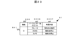
- the figure which shows the functional composition information 61c of the function D in 4th Embodiment The figure which shows an example of the function limitation information 91 in 4th Embodiment
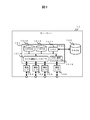
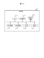
- FIG. 1 is a diagram showing a configuration of a functional configuration information management system S according to the first embodiment.
- the functional configuration information management system S includes a vehicle 1 and a server 2.
- the vehicle 1 and the server 2 are connected via the Internet 3 that connects the access network and the base, and the access network 4 provided by the communication service provider.
- the vehicle 1 includes a gateway 10, a communication module 11, a Human Machine Interface (HMI) 12, and a plurality of ECUs (electronic control units).
- the gateway 10, the communication module 11, and the HMI 12 are connected by the in-vehicle network 10a.
- the ECU provided in the vehicle 1 is not particularly limited, but in the present embodiment, for example, an engine control ECU 13, a brake control ECU 14, an automatic driving ECU 15, and an advanced driver assistance system (ADAS) ECU 16 are provided.
- the gateway 10 and these ECUs are connected by the in-vehicle network 10b. These ECUs connected to the gateway 10 are collectively referred to as "subordinate ECUs" below.
- the in-vehicle network 10a and the in-vehicle network 10b adopt one of known communication standards such as Control Area Network (CAN) (registered trademark), Local Internet Network (LIN), and FlexRay and Ethernet (registered trademark).
- CAN Control Area Network
- LIN Local Internet Network
- FlexRay and Ethernet registered trademark
- the in-vehicle network 10b is composed of CAN
- the in-vehicle network 10a is composed of Ethernet.
- the same communication standard may be adopted for the in-vehicle network 10a and the in-vehicle network 10b.
- each component in the vehicle such as various ECUs is connected to the storage battery by a power line to receive electric power.
- the gateway 10 relays communication data between subordinate ECUs, updates software of subordinate ECUs, and confirms consistency of software installed in subordinate ECUs.
- software consistency confirmation is also referred to as "verification” or “verification processing”.
- the gateway 10 does not update the software of the gateway 10 itself and check the consistency, but the gateway 10 may update the software of the gateway 10 itself and check the consistency.
- “verification” and “matching” are used interchangeably.
- the communication module 11 relays communication between the gateway 10, the HMI 12, and the subordinate ECU and the server 2.
- the HMI 12 is a device for presenting information to a user who is an occupant of the vehicle 1 and receiving input from the user.
- the HMI 12 is composed of a display device that displays a screen, an input device such as various switches, or a touch panel that combines these.
- the engine control ECU 13 controls the engine.
- the brake control ECU 14 controls the brake.
- the automatic driving ECU 15 recognizes the environment, gives an instruction to start the vehicle, and the like during automatic driving.
- the ADAS ECU 16 performs driving support control such as automatic braking.
- the server 2 transmits the function configuration information 61 to the gateway 10.
- the gateway 10 manages the functional configuration of the vehicle 1 based on the functional configuration information 61.
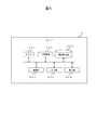
- FIG. 2 is a block diagram showing a hardware configuration of the gateway 10.
- the gateway 10 includes a microcomputer 101, a FROM (FlashROM) 102, a communication I / F (interface) 104 for CAN, and a communication I / F 105 for Ethernet.
- the microcomputer 101 includes a CPU 1011, a SRAM 1012, a FROM 1013, a CAN communication controller 1014, and an Ether communication controller 1015.
- the CPU 1011 of the microcomputer 101 executes a program stored in the FROM 1013, controls other components in the gateway 10, and gives a data transmission / reception instruction to other devices connected by the in-vehicle network to control the gateway 10. Make it work.
- ASIC Application Specific Integrated Circuit
- FPGA Field Programmable Gate Array
- the FROM 102 is a non-volatile memory, and information received from the server 2 is stored in the FROM 102.
- the CAN communication controller 1014 is an interface for CAN communication, and transmits / receives data to / from a subordinate ECU connected to the in-vehicle network 10b via the in-vehicle network 10b based on an instruction from the microcomputer 101.
- the Ethernet communication controller 1015 is an interface for Ethernet communication, and transmits / receives data to / from a device connected to the in-vehicle network 10a via the in-vehicle network 10a based on an instruction from the microcomputer 101.
- FIG. 3 is a block diagram showing a hardware configuration example of the engine control ECU 13.
- each ECU to which the software is updated has at least the hardware configuration shown in FIG.
- the engine control ECU 13 includes a microcomputer 131 and a communication I / F 133 for CAN.
- the microcomputer 131 includes a CPU 1311, SRAM 1312, FROM 1313, a communication controller 1314, and an I / O controller 1315.
- the microcomputer 131 executes a control program stored in the FROM 1313 to control other components in the engine control ECU 13 and a sensor / actuator 132 connected via I / O, and is connected by an in-vehicle network.
- Engine control is performed by instructing data transmission / reception with the equipment of.
- the sensor / actuator 132 executes engine control while acquiring data required for engine control according to instructions from the microcomputer 131.
- the version information of the control program stored in the FROM 1313 is also stored in the FROM 1313.
- the FROM 1313 also stores an ECU ID, which is identification information that identifies the type and function of the ECU.
- the ECU ID is also called a "part number” or a "model number”.
- the ECU ID is not a so-called serial number for identifying individual products, but can be replaced with another product having the same ECU ID when the ECU fails.
- FIG. 4 is a block diagram showing a configuration of a control program 130 that operates on the engine control ECU 13. However, in each of the ECUs to which the software is updated in the present embodiment has at least the same configuration as the control program 130 shown in FIG.
- the control program 130 that realizes the functions of the ECU 13 is stored in the FROM 1313 of the microcomputer 131 and executed by the CPU 1311.
- a functional group is represented as a block, and each block may be divided into a plurality of blocks, or some blocks may be integrated.
- the control program may be realized by one software or may be realized by a combination of two or more softwares.
- the control program 130 includes a control processing unit 13001, an update control unit 13003, an information management unit 13004, and a communication control unit 13005.
- the control processing unit 13001 controls the I / O controller 1315 and controls the sensor / actuator 132 to perform engine control.
- the stop unit 130011 receives a stop command and a restart command from the gateway 10 via the communication control unit 13005, and performs stop / restart control of the function.
- the update control unit 13003 receives an operation command from the gateway 10 and data used for software update via the communication control unit 13005, and controls the software update.
- the information management unit 13004 reads the software version information and ECU ID stored in the FROM 1313, and rewrites the version information when the software is updated.
- the communication control unit 13005 controls the communication controller 1314 according to the instruction of the update control unit 13003 or the like, and communicates with the device connected to the in-vehicle network 10b. At the time of communication, the CAN frame is analyzed and configured. Further, the communication control unit 13005 generates and analyzes a command based on a diagnostic communication protocol such as UDS.
- a diagnostic communication protocol such as UDS.
- the functions of the vehicle 1 are realized by one ECU or by the cooperation of a plurality of ECUs.
- Collaboration means that they operate in cooperation with each other, but it is not always necessary for each ECU to recognize other ECUs that cooperate with each other, and as a result, a plurality of ECUs may be involved in the realization of the function.
- a certain function X is realized by the collaboration between the engine control ECU 13 and the automatic operation ECU 15, in the present embodiment, the engine control ECU 13 and the automatic operation ECU 15 are said to "configure” the function X. It is also said that the engine control ECU 13 and the automatic operation ECU 15 "realize" the function X.
- FIG. 5 is a block diagram showing a configuration example of the server 2.
- the server 2 includes a CPU 201, a main storage unit 202, an auxiliary storage unit 203, a communication unit 204, an input unit 205, and a display unit 206.
- the CPU 201 executes a server program stored in the auxiliary storage unit 203 or the like on the main storage unit 202 to control registration and distribution of functional configuration management information.
- the auxiliary storage unit 203 stores functional configuration management information and data for updating ECU software to be distributed to the vehicle.
- the communication unit 204 transmits / receives data to / from the vehicle 1 via the Internet.
- the input unit 205 receives operations and input information from an operator who operates the server 2.
- the display unit 206 provides the operator who operates the server 2 with information regarding the registration of functional configuration management information.
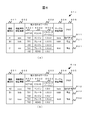
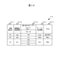
- FIG. 6 is a diagram showing an example of the function configuration information 61 generated by the server 2 and managed by the table management unit 10001 of the diagnostic device 5 and the gateway 10.
- FIG. 6A shows the function configuration information 61a which is the function configuration information 61 before the change
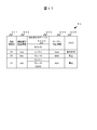
- FIG. 6B shows the function configuration information 61b which is the function configuration information 61 after the change.
- FIG. 6 shows an example in which the function configuration information 61 is managed as a table and the configuration information for each function is recorded.
- the functional configuration information 61 has a plurality of records.
- Each record of the function configuration information 61 includes fields of a function identification ID 601, a function identification verification information 602, a combination table 603, a combination table verification information 604, and a flag 605.
- the functional configuration information 61 has three records of R11, R21, and R31, but the number of records possessed by the functional configuration information 61 may be 1 or more, and there is no upper limit.
- the fields of the function identification verification information 602 and the table verification information 604 store the result of the calculation by the CPU 201 of the server 2. Information on other fields is entered by the operator.
- the function identification ID 601 is a field in which identification information for identifying the combination of the hardware and software of the ECU constituting the function is stored.
- "software" here is a concept that includes the version number. Therefore, the value of the function identification ID 601 is changed not only when the ECU ID registered in the combination table 603 is changed, but also when the software version is changed.
- the function identification ID 601 is, for example, a combination of a character string that identifies a function and a number corresponding to a change in the ECU ID or version.
- the function identification verification information 602 is an area for storing the integrity verification information of the function identification ID 601.
- the integrity verification information of the function identification ID 601 is, for example, a digital signature of the function identification ID 601.
- the combination table 603 is composed of NET ID6031, ECU ID6032, and software version 6033.
- the combination table 603 stores information on the combination of ECU hardware and software related to the function indicated by the function identification ID 601.
- the NET ID6031 stores an ID indicating the identification information of the ECU on the in-vehicle network.
- the vehicle-mounted network 10b is CAN
- the CAN ID is stored in the NET ID 6031
- the vehicle-mounted network 10b is Ethernet, the IP address and MAC address are stored.
- NET ID6031 may include information (not shown) such as a network type and a channel number.
- Information for identifying the type and function of the ECU is stored in the ECU ID 6032.
- the ECU ID 6032 for example, an "engine” which is identification information indicating the type and function of the engine control ECU 13 is stored. Part numbers and the like may be used as the identification information of the ECU. That is, the NET ID6031 is an identifier on the ECU network, while the ECU ID6032 is an identifier indicating the type of the ECU. Further, in the following, the NET ID 6031 may be referred to as "first identification information”, and the ECU ID 6032 may be referred to as "second identification information”.
- the software version 6033 is a field in which information for identifying the version of the software installed in the ECU is stored.
- the information stored in the ECU ID 6032 and the information stored in the software version 6033 are collectively referred to as "configuration information”.
- the combination table verification information 604 is an area for storing the integrity verification information of the information registered in the combination table 603.
- the combination table verification information 604 is, for example, a digital signature of a value obtained by concatenating the function identification ID 601, the ECU ID 6032, and the software version 6033.
- the flag 605 stores information indicating whether or not to allow the operation continuation of the function indicated by the function identification ID 601 when there is a contradiction between the information registered in the combination table 603 and the information collected from the subordinate ECU. .. "Operation permission” is stored when continuous operation is permitted, and “stop” is stored when operation permission is not permitted and stop is required.
- the record R1 in FIG. 6A is a record in which information related to the function A whose function identification ID is indicated by "A1" is stored.
- “Aaa” is stored in the field of the function identification verification information 602 of the record R1
- "700” is stored in the field of NET ID6031
- "engine” indicating that it is the engine control ECU 13 is stored in the field of ECU ID6032.
- Stored, "1.0.0.0” is stored in the field of software version 6033
- "taaa” is stored in the field of combination table verification information 604, and inconsistency occurs in the field of flag 605. Even if this is done, an "operation permission" that permits the continuation of the operation of the function is stored.
- the record R2 in FIG. 6A is a record in which information related to the function B whose function identification ID is indicated by "B1" is stored.
- “Bbb” is stored in the field of the function identification verification information 602 of the record R2
- "701” is stored in the field of NET ID6031
- "brake” indicating that it is the brake control ECU 14 is stored in the field of ECU ID6032. It is stored, “1.0.0.0” is stored in the field of software version 6033, “tbbb” is stored in the field of combination table verification information 604, and an inconsistency occurs in the field of flag 605. If this is the case, a "stop” indicating that the operation of the function needs to be stopped is stored.
- the record R3 in FIG. 6A is a record in which information related to the function C whose function identification ID is indicated by "C1" is stored.
- “Ccc” is stored in the field of the function identification verification information 602 of the record R3. Since there are three ECUs constituting the function C, "700", “701”, and “702” are stored in the fields of NET ID6031, and “engine”, “brake”, and “ADAS” are stored in the fields of ECU ID6032, respectively. It is stored, and "1.0.0.0", “1.0.0.0”, and “1.0.0.0” are stored in the fields of software version 6033, respectively.
- "Tccc” is stored in the field of the combination table verification information 604 of the record R3, and "stop” indicating that the operation of the function needs to be stopped when an inconsistency occurs is stored in the field of the flag 605. Has been done.
- one function may be composed of any number of ECUs, and the upper limit of the number of ECUs constituting one function is limited. Absent.
- FIG. 6B is a diagram showing the function configuration information 61b which is the updated function configuration information 61 when the software of the engine control ECU 13 is updated from the function configuration information 61a shown in FIG. 6B.
- the software version of the engine control ECU 13 has been updated from "1.0.0.0" to "1.0.0.1".
- the records R12, R22, and R32 shown in FIG. 6B correspond to the records R11, R21, and R31 shown in FIG. 6A, respectively.
- the software version 6033 of the record whose ECU ID 6032 is the "engine” has been updated to "1.0.0.1". ..
- the function identification ID 601 of the functions of the record D101b and the record D103b including the engine control ECU 13 as a component is updated to "A2" and "C2", respectively.
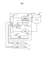
- FIG. 7 is a block diagram showing a configuration of a gateway program 100 operating on the gateway 10.
- the gateway program 100 that realizes the function of the gateway 10 is stored in the FROM 1013 of the microcomputer 101 and executed by the CPU 1011.
- a functional group is represented as a block, and each block may be divided into a plurality of blocks, or some blocks may be integrated.
- the control program may be realized by one software or may be realized by a combination of two or more softwares.
- the gateway program 100 includes a control unit 10000, a table management unit 10001, a calculation determination unit 10002, an acquisition unit 10004, a stop control unit 10005, and a communication control unit 10006.
- the control unit 10000 controls the table management unit 10001, the calculation determination unit 10002, the acquisition unit 10004, the stop control unit 10005, and the communication control unit 10006.
- the table management unit 10001 manages the function configuration information 61 stored in the FROM 1013.
- the calculation determination unit 10002 calculates the verification value using the configuration information acquired from the acquisition unit 1004, and determines the consistency with the table verification information 604 included in the function configuration information 61.
- the calculation determination unit 10002 outputs the determination result to the stop control unit 10055.
- the method of calculating the verification value is the same as that of the server 2. If the value used by the calculation determination unit 10002 for calculating the verification value, that is, the ECU ID and the software version are the same as the value used for the calculation by the server 2, the verification value and the table verification information 604 are matched.
- the acquisition unit 1004 acquires configuration information such as the ECU ID and software version from the ECU based on the information managed by the table management unit 10001, and outputs the configuration information to the verification information calculation unit.
- the stop control unit 10055 controls the operation continuation / stop of the function in which the inconsistency has occurred, based on the flag indicating the operation permission / stop managed by the table management unit 10001 and the output information of the calculation determination unit 10002.
- the communication control unit 10006 controls the CAN communication controller 1014 and the Ether communication controller 1015 in accordance with the instructions of the stop control unit 10055 and the like, and communicates with the devices connected to the in-vehicle networks 10a and 10b.
- the communication control unit 10007 analyzes and generates packets such as TCP / IP and UDP / IP. Further, when communicating with a device connected to the in-vehicle network 10b, the communication control unit 10006 analyzes and generates a CAN frame. Since the communication control unit 10006 can communicate with the outside of the vehicle 1 via the communication module 11, it can also be called an "external communication unit".
- FIG. 8 is a conceptual diagram showing verification of the table verification information 604 in the present embodiment. Step numbers are assigned to FIG. 8 for convenience in order to show the correspondence with the following description. This step number does not correspond to the step number in the flowchart described later.
- the private key SK is stored in advance in the server 2, and the public key PK is stored in advance in the gateway 10.
- the CPU 201 of the server 2 creates a bit string X in which configuration information is connected for each function according to a predetermined rule (S901). For example, in the case of only the ECU "engine control ECU” that constitutes the function A as shown in FIG. 6, in order to create the table verification information 604 of the function A, the CPU 201 sets the "engine” according to a predetermined rule, for example, UTF-. Convert to the character code number of 8 to obtain "0x834712345", and convert the version number "1.0.0.0" according to a predetermined rule to obtain "0x1000". Then, "0x8347123451000" obtained by concatenating these two bit strings is defined as the bit string X.
- a predetermined rule for example, UTF-.
- rules such as arranging the bit strings when creating the bit string X in ascending order of NET ID are predetermined.
- the CPU 201 targets the bit string X and creates a digital signature Y using the private key SK (S902).
- the created digital signature Y is stored as the table verification information 604 of the function configuration information 61 and transmitted to the gateway 10.
- the method for creating the digital signature Y is shared with the gateway 10 in advance.
- the gateway 10 refers to the function configuration information 61 received from the server 2, reads the configuration information from the ECU for each function, and creates a bit string Z which is a verification value according to a predetermined rule (S903).
- the rule of the bit string Z is the same as the creation rule of the bit string X stored in the server 2.
- the gateway 10 decodes the table verification information 604 stored in the function configuration information 61, that is, the digital signature Y, using the public key PK to obtain the bit string X (S904).
- the gateway 10 determines whether the verification is successful or not by determining whether or not the bit string X and the bit string Z are the same (S905).
- the digital signature Y may be created for the hash value of the bit string X or the XOR value of the bit string X and the predetermined value without using the bit string X as it is.
- S903 and S904 in the above description may be executed in a different order or may be executed substantially at the same time.
- the bit string Z is also referred to as a “verification value”.
- the comparison target of the bit string Z is the bit string X as described above, but in the following description, in order to avoid redundant description, simply "determine the matching between the bit string Z and the digital signature Y" or “verification value and table verification”. The consistency of the information 604 is determined. "
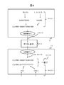
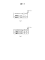
- FIG. 9 is a diagram showing an example of a display screen displayed on the HMI 12.
- the display G1a shown in FIG. 9A is an example of a screen showing to the user that a mismatch between the functional configuration information and the actual configuration has been detected. If the function is stopped due to inconsistency, information indicating that the function is stopped may be further displayed on this screen.
- the display G1b shown in FIG. 9B is a screen example showing to the user that a part of the function has been stopped because the function configuration information is inconsistent.
- the display G1c shown in FIG. 9C is an example of a screen prompting the user to contact the dealer for recovery because the function configuration information is inconsistent and countermeasures cannot be taken.
- the display G1d shown in FIG. 9D is a screen example showing to the user that the inconsistency of the function configuration information has been recovered and a part of the functions has become widespread.
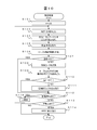
- FIG. 10 is a flowchart showing a verification process in the gateway 10. The process shown in FIG. 10 is executed when the ignition switch of the vehicle 1 is turned on.
- the gateway 10 may be connected to the ignition switch by a signal line and directly receive a signal indicating an on / off state from the ignition switch, or may receive an operation command signal from an ECU (not shown) connected to the ignition switch. You may start the operation.
- control unit 10000 first sets the processing handling record x to 1 (S101).
- the function configuration information 61 is shown in FIG. 6A
- the gateway program 100 repeats the processes of S103 to S111 for the number of records stored in the function configuration information 61.
- the control unit 10000 reads the NET ID of the processing target record x in the function configuration information 61, and instructs the acquisition unit 1004 to read the configuration information from the ECU having the NET ID (S103).
- the acquisition unit 1004 reads the configuration information from the ECU, that is, the combination of the ECU ID and the software version, and passes the read configuration information to the calculation determination unit 10002 via the communication control unit 10006 (S104).
- the configuration information is read out for all the NET IDs.
- the calculation determination unit 10002 calculates the verification information using the received configuration information (S105).
- the calculation determination unit 10002 reads out the table verification information 604 in the processing handling record x of the function configuration information 61, and determines the consistency with the verification value calculated in S105 (S106). When the calculation determination unit 10002 determines that the verification value and the table verification information 604 match (S107: YES), the calculation determination unit 10002 proceeds to S112 and the control unit 10000 confirms the presence or absence of an unconfirmed record. When the control unit 10000 determines that there is no unconfirmed record (S112: NO), the control unit 10000 confirms whether or not the confirmed record is inconsistent.
- control unit 10000 determines that there is no inconsistency, that is, the verification value calculated by the calculation determination unit 10002 for all the records of the function configuration information 61 and the table verification information 604 read from the function configuration information 61 match (S113). : NO) ends the process.
- control unit 10000 determines that there is an inconsistency, that is, the verification value calculated by the calculation determination unit 10002 and the table verification information 604 read from the function configuration information 61 do not match in any record of the function configuration information 61. (S113: YES), the HMI is instructed to display the screen G1a of FIG. 9 (S114), and the process ends. If there is an unconfirmed record (S112: YES), the control unit 10000 updates the processing target record x to the next record (S115), and returns to S103.
- the control unit 10000 When it is determined that the control unit 10000 does not match (S107: NO), the control unit 10000 records a failure code indicating that the version information does not match, that is, a DTC (diagnostic trouble code) code (S108).
- the stop control unit 10055 receives the processing target record X and the comparison result from the control unit 10000, and reads the flag 605 of the corresponding record from the function configuration information 61 (S109). When the read flag 605 is "operation permission" (S110: YES), the stop control unit 10055 continues the process without doing anything.
- the read flag 605 is not "operation permission" (S110: NO)
- the related ECU registered in the processing target record X of the function configuration information 61 is instructed to stop the function via the communication control unit 10006. (S111). The above is the description of FIG.
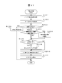
- FIG. 11 is a flowchart showing a recovery process in the gateway 10.
- the process shown in FIG. 11 is executed after the process shown in FIG. 10 is completed and when any record of the function configuration information 61 is inconsistent.
- the process shown in FIG. 11 does not necessarily have to wait for the completion of the process shown in FIG. 10 before starting. For example, when a negative determination is made in S107, execution may be started in parallel with S108.
- the control unit 10000 first transmits the configuration information including the information in which the functional configuration information is inconsistent to the server 2 (S201).
- the server 2 transmits one of the following three responses based on the configuration information received from the gateway 10.
- the first response is an instruction to update the function configuration information 61
- the second response is an instruction to update the software of the ECU
- the third response is an instruction to update the function configuration information 61 and the software of the ECU.
- the server 2 selects which of the first to third responses is to be made based on the update date and time of the function configuration information 61, the update date and time of the software of the ECU, and the version number of the software.
- the server 2 may return a response that does not include the update instruction.
- control unit 10000 When the control unit 10000 receives the response from the server 2 (S202), it determines whether the update instruction is included in the response. When the control unit 10000 determines that the update instruction is not included (S203: NO), the control unit 10000 instructs the HMI 12 to display the screen G1c shown in FIG. 9 (c) (S204), and ends the process shown in FIG. ..
- the control unit 10000 determines whether or not the response from the server 2 includes the update instruction of the function configuration information 61.
- the control unit 10000 determines that the update instruction of the function configuration information 61 is included (S205: YES)
- the control unit 10000 updates the function configuration information 61 (S206).
- the control unit 10000 determines whether or not the response from the server 2 includes the software update instruction of the ECU.
- the control unit 10000 determines that the software update instruction of the ECU is not included (S207: NO)
- the control unit 10000 instructs the ECU that has stopped the function to restore the function (S209), and the HMI 12 is shown in FIG. 9 (d).
- the display of the screen G1d shown is instructed (S210), and the process shown in FIG. 11 ends.
- the control unit 10000 determines that the software update instruction of the ECU is included (S207: YES)
- the control unit 10000 executes the software update process of the ECU (S208).
- control unit 10000 instructs the ECU that has stopped the function to restore the function (S209), and instructs the HMI 12 to display the screen G1d shown in FIG. 9D (S210). The process shown in FIG. 11 is terminated.
- FIG. 12 is a sequence diagram showing a procedure for updating software of the ECU.
- the engine control ECU 13 is described as a software update processing target as an example of processing, but the sequence described below is common regardless of the processing target ECU.
- the gateway 10 first reads the ECU ID and software version from the engine control ECU 13 to be updated (S2081). The gateway 10 then transmits the collected ECU ID and software version, that is, configuration information to the server (S2082). The server 2 determines whether or not the software of the vehicle has been updated based on the received configuration information, and transmits the resulting update information to the gateway 10 (S2083). Next, the gateway 10 downloads the data required for the update from the server 2 (S2084). The data required for the update includes new software and the updated functional configuration information 61.
- the gateway 10 controls the engine control ECU 13 to be updated and updates the software of the engine control ECU 13 (S2085).
- the gateway 10 updates the function configuration information 61 (S2086).
- FIG. 13 is a diagram showing an example of a registration screen of the function configuration information 61 in the server 2.
- the registration screen G2 is displayed on the display unit 206 of the server 2.
- the registration screen G2 of the function configuration information 61 is composed of a target function G21, a function identification ID G22, a function realization ECU G23, a mismatch operation G24, a registration button G25, and a line addition button G26.
- the target function G21 is an area for setting information for identifying a function to be managed such as an emergency braking function, and in this example, "function C" is set as shown by reference numeral G21a.
- the function identification ID G22 is an area for setting identification information for uniquely identifying the configuration to be managed, and in this example, "C1" is set as shown by the reference numeral G22a.
- the related ECU G23 is an area for setting information for uniquely identifying the ECU that realizes the target function G21, and is composed of a NET ID, an ECU ID, and a software version.
- the function C is realized by the three ECUs represented by the reference numerals G23a to G23c.
- the ECU represented by the reference numeral G23a has a NET ID of "700", an ECU ID of "engine”, and a software version of "1.0.0.0".
- the ECU indicated by reference numeral G23b has a NET ID of "701", an ECU ID of "brake”, and a software version of "1.0.0.0".
- the ECU represented by the reference numeral G23c has a NET ID of "702", an ECU ID of "ADAS”, and a software version of "1.0.0.0".
- the inconsistent operation G24 is an area picture for setting the operation of the function when an inconsistency is detected in the configuration information of the function shown in the target function G21.
- "stop" is set as shown by the reference numeral G24a.
- the registration button G25 is a button for registering the input information in the server 2, and when the operator presses this button, the values of the fields of the function identification verification information 602 and the table verification information 604 are calculated by the CPU 201.
- the row addition button G26 is a button for increasing the input field of the function realization ECU.
- the gateway 10 is connected to a plurality of ECUs. Each of the plurality of ECUs constitutes its own function by one or more ECUs. For each function, the gateway 10 is an external communication unit that receives first identification information of one or more ECUs constituting the function, that is, NET ID 6031 and first verification information, that is, function configuration information 61 including table verification information 604, that is, The communication control unit 10006, the software version 6033 mounted on the ECU and the second identification information of the ECU, that is, the acquisition unit 1004 for acquiring the ECU ID 6032 from each of the plurality of ECUs, and all the functions constituting the functions for each function.
- first identification information of one or more ECUs constituting the function that is, NET ID 6031 and first verification information, that is, function configuration information 61 including table verification information 604, that is,
- the communication control unit 10006, the software version 6033 mounted on the ECU and the second identification information of the ECU that is, the acquisition unit 1004 for acquiring the ECU ID 6032 from
- Calculation determination unit 10002 that calculates the second verification information, that is, the bit string Z, using the software version 6033 that is the version information of the ECU and the software version 6033 acquired by the acquisition unit and the second identification information of all the ECUs constituting the function, that is, the ECU ID 6032. And, for each function, a calculation determination unit 10002 for determining the consistency of the first verification information and the second verification information is provided. Therefore, the gateway 10 can confirm the configuration information for each function for all the functions configured by the ECU connected to the gateway 10.
- the software versions installed in the plurality of ECUs are a combination as intended. For example, the operation may not be guaranteed with a combination that has not been verified in advance. Also, since software updates can be performed via wireless communication, there is a higher possibility that the combination of software versions will be unplanned compared to when the software is updated by bringing it to a specialty store. Further, when an ECU fails, it may be replaced with another ECU having the same model number, and the software version of the ECU may not match the ECU before the replacement. In such a case, by performing the verification process shown in the present embodiment, it is possible to confirm the configuration information for each function, find a problem, and confirm that there is no problem.
- the first identification information is an identifier on the ECU network, that is, NET ID6031.
- the second identification information is an identifier indicating the type of ECU, that is, ECU ID 6032.
- the function configuration information 61 includes a flag 605 indicating permission or denial of execution at the time of inconsistency for each function.
- the stop control unit 10055 is a function related to the second verification information determined to be inconsistent, and is a function related to the second verification information in the function configuration information. Stop the function that has a flag indicating that the execution is rejected when the flag is inconsistent. Therefore, the gateway 10 can stop the function at the time of inconsistency according to the setting of the flag 605.
- the control unit 10000 determines the function configuration information 61 and the software of the ECU based on the command received from the Ether communication controller 1015. Update at least one of them. Therefore, the gateway 10 can update at least one of the function configuration information 61 and the software of the ECU at the time of inconsistency.
- the control unit 10000 records the occurrence of the inconsistency in the FROM 102, which is a storage unit, as a failure code. .. Therefore, the occurrence of inconsistency can be confirmed ex post facto by referring to FROM 102.
- the control unit 10000 causes the display unit, that is, the HMI 12 to display that the inconsistency has occurred. Therefore, the occupant of the vehicle 1 can know the occurrence of the inconsistency by the display of the HMI 12.
- the gateway 10 is mounted on the vehicle 1.
- the acquisition unit 1004 and the calculation determination unit 10002 start operation when the ignition switch of the vehicle 1 is turned on. Therefore, by operating when the vehicle 1 is started, software inconsistency can be detected before the vehicle 1 starts traveling or while the vehicle 1 is traveling at a low speed.
- a device other than the gateway 10 may realize the confirmation of the configuration information of each function. For example, it may be executed by a diagnostic device that can be connected to the vehicle 1.
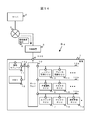
- FIG. 14 is a diagram showing the configuration of the functional configuration information management system Sa in the first modification.
- FIG. 14 is different from the first embodiment in that the diagnostic device 5 is added.
- the diagnostic device 5 receives the functional configuration information 61 transmitted by the server 2.
- the diagnostic device 5 and the gateway 10 are connected via a general-purpose connector 600 such as OBD2.
- the communication module 11 and the server 2 are not connected in FIG. 14, when the software of the ECU is updated, the communication module 11 communicates with the server 2 as in the first embodiment.
- FIG. 15 is a block diagram showing a configuration example of the diagnostic device 5.
- the diagnostic device 5 includes a CPU 501, a main storage unit 502, an auxiliary storage unit 503, a first communication unit 504, a second communication unit 505, an input unit 506, and a display unit 507.
- the CPU 501 executes a program stored in the auxiliary storage unit 503 or the like on the main storage unit 502 to control the function configuration management.
- the auxiliary storage unit 503 stores functional configuration management information and data for updating ECU software to be distributed to the vehicle.
- the first communication unit 504 transmits / receives data to / from the server 2 via the Internet 3.
- the second communication unit 505 transmits / receives data to / from the vehicle 1.
- the input unit 506 receives operations and input information from an operator who operates the diagnostic device 5.
- the display unit 507 displays the function configuration management information to the operator who operates the diagnostic device 5.
- the functional configuration information 61 also includes the ECU ID 6032 and the software version 6033.
- the gateway 10 does not particularly require the ECU ID 6032 and the software version 6033 including the verification process, it is not necessary to include the ECU ID 6032 and the software version 6033 in the function configuration information 61.
- FIG. 16 is a diagram showing an example of the functional configuration information 64 in the modified example 1.
- the combination table 603 is composed only of the NET ID 6031.
- the operation of the gateway 10 is the same as that of the first embodiment.
- the gateway 10 did not have an opportunity to refer to the ECU ID 6034 and the function version 6035 described in the function configuration information 61 received from the server 2. Therefore, even if the ECU ID 6034 and the function version 6035 are deleted from the function configuration information 64, there is no effect.
- the functional configuration information 61 also includes the NET ID 6031 and the software version 6033. However, the functional configuration information 61 does not have to include the NET ID 6031 and the software version 6033.
- FIG. 17 is a diagram showing an example of the functional configuration information 65 in the modified example 3.
- the combination table 603 is composed only of the ECU ID 6032.
- S103 to S105 of FIG. 10 of the gateway 10 are changed as follows. That is, the gateway 10 transmits a message inquiring about the ECU ID and the software version to all the connected ECUs. Then, for each function described in the function configuration information 65, verification information, that is, the bit string Z in FIG. 8 is created using the acquired ECU ID and software version.
- the gateway 10 uses the NET ID 6031 to specify the ECU constituting the function for each function and make an inquiry.
- the function configuration information 65 does not include the NET ID 6031, all the connected ECUs are inquired.
- the gateway 10 since the ECU constituting each function in the function configuration information 65 is specified by the ECU ID 6032, the gateway 10 uses the ECU ID and the version information obtained as an answer to the inquiry to set the bit string Z for each function. Can be created.
- the flag 605 is included in the functional configuration information 61.
- the gateway 10 is configured to allow uniform operation in S110 of FIG. 10 or not uniformly allow operation.
- the function may be restricted instead of stopping the operation. Function limitation is to reduce the processing power and the types of functions to be realized.
- the stop control unit 10055 stops or functions the function related to the second verification information determined to be inconsistent. To limit. Therefore, it is possible to uniformly stop or limit the functions in which software inconsistency is detected.
- Modification 5 In the first embodiment described above, information is verified between the server 2 and the gateway 10 using a public key cryptosystem.
- the verification method is not particularly limited, and replacement with various known methods and combination of known methods are also included in the scope of the present invention. For example, even if the same public key cryptosystem is used, verification may be performed by encrypting with the private key SK at the server 2 and decrypting with the public key PK at the gateway 10. Further, a symmetric encryption method may be used instead of the public key encryption method, or a message authentication code or salt may be used.
- the recovery / rejection flag may be included in the response from the server 2 to the gateway 10.
- the control unit 10000 of the gateway 10 instructs the ECU in step S209 of FIG. 11 to restore the function only to the ECU for which the flag indicating that the restoration is possible is set by the restoration possibility flag.
- the gateway 10 may verify the function identification verification information 602 in the same manner as the table verification information 604. In this case, the gateway 10 verifies the function identification verification information 602 immediately before S108 in FIG. 10, and proceeds to S112 if the verification is successful, and proceeds to S108 if the verification fails. According to this modification, the function identification ID 601 can be verified.
- the server 2 may further use at least one of the function identification ID 601 and the NET ID 6031 for calculating the table verification information 604.
- the gateway 10 also performs the same calculation in the verification process.
- the gateway 10 starts the verification process when the ignition switch of the vehicle 1 is turned on.
- the gateway 10 may start the verification process by receiving an operation command from the outside.
- the gateway 10 may receive an operation command from the outside of the vehicle 1 via the communication module 11, or may start the operation by receiving an operation command from an ECU or the like mounted on the vehicle 1.
- the function configuration information 61 is created by the server 2 based on the information input by the operator.
- the operator may create the function configuration information 61 in advance, and the operator may store the function configuration information 61 itself in the auxiliary storage unit 203 of the server 2.
- FIGS. 18 to 19 A second embodiment of the gateway, which is an arithmetic unit according to the present invention, will be described with reference to FIGS. 18 to 19.
- the same components as those in the first embodiment are designated by the same reference numerals, and the differences will be mainly described.
- the points not particularly described are the same as those in the first embodiment.
- This embodiment is different from the first embodiment in that the software version is mainly managed in the ECU for each function. Further, in the present embodiment, the information stored in the functional configuration information is different from that in the first embodiment.
- FIG. 18 is a diagram showing an example of function-specific version information 951 stored in each ECU in the second embodiment.
- the engine control ECU 13 is used as a specific example
- FIG. 18A shows the function-specific version information 951a of the engine control ECU 13 before the update
- FIG. 18B shows the function-specific version of the engine control ECU 13 after the update.
- Information 951b is shown.
- the engine control ECU 13 contributes to the realization of the functions A and C. Therefore, the function-specific version information 951 stored in the engine control ECU 13 includes the software version "1.0.0.0" and the function A version "1" as shown in FIG. 18A. It is composed of "1" which is a function C version.
- the function-specific version information 950 is updated with the software update.
- the software version is updated to "1.0.1.0” and the function A version is updated to "2".
- the function C version has not changed from "1".
- FIG. 19 is a diagram showing an example of the functional configuration information 62 according to the present embodiment.
- FIG. 19A is a diagram showing the function configuration information 62a before the update
- FIG. 19B is a diagram showing the function configuration information 62b after the update.
- the example shown in FIG. 19 (a) includes records of R41, R51, and R61
- the example shown in FIG. 19 (b) includes records of R42, R52, and R62. Comparing the functional configuration information 62 in the present embodiment with the functional configuration information 61 in the first embodiment, the field of software version 6033 in the functional configuration information 61 is deleted, and instead the fields of DID 6034 and functional version 6035 are deleted. Is added.
- DID6034 stores identification information used when reading a version for each function from the ECU.
- DID6034 is the identification information of the function set for reading the version information.
- the DID 6034 may have a 1: 1 correspondence with the function common to all ECUs, or the correspondence between the DID and the function may be different for each ECU.
- FIG. 19 shows that in the record R61, the version information of the function C is read by "F003", which is a DID 6034 common to all three ECUs.
- record R41 and record R42 are different, but record R51 and record R61 are the same as record R52 and record R62. This is because the software version information itself is not stored in the function configuration information 62, but only the version information of each function of each software is stored in the function configuration information 62.
- each ECU performs the following operation when it receives an inquiry about software version information from the gateway 10 together with the DID 6034. That is, the ECU refers to the function configuration information 62 stored in the FROM 1313 and returns the version information of the function corresponding to the received DID6034.
- the server 2 creates the bit string X by using the ECU ID 6032 and the function version 6035, and creates the table verification information 604 which is the digital signature thereof.
- the gateway 10 creates a bit string Z using the ECU ID 6032 and the function version 6035, and verifies the table verification information 604.
- the server 2 may further use the value of DID6034 in creating the bit string X.
- the gateway 10 also uses the value of DID6034 in creating the bit string Z.
- FIGS. 20 to 21 A third embodiment of the gateway, which is an arithmetic unit according to the present invention, will be described with reference to FIGS. 20 to 21.
- the same components as those in the second embodiment are designated by the same reference numerals, and the differences will be mainly described.
- the points not particularly described are the same as those in the second embodiment.
- the information stored in the functional configuration information is mainly different from that in the second embodiment.
- FIG. 20 is a diagram showing an example of function-specific version information 952 stored in each ECU in the present embodiment.
- the engine control ECU 13 is used as a specific example
- FIG. 20A shows the function-specific version information 952a before the update of the engine control ECU 13
- FIG. 20B shows the function-specific version after the engine control ECU 13 is updated.
- Information 952b is shown.
- the function-specific version information 952 is composed of 6 bytes, and indicates information that uniquely identifies each software version of the boot loader, BSW, ASW, calibration data, function A, and function C from the beginning.
- the value of each digit of the function-specific version information 952 is updated as the software of the target portion is updated.
- the function-specific version information 952 is actually composed of only a 6-byte value.
- the function-specific version information 952a before the update shown in FIG. 20A is "1,1,1,1,1,1". Since the updated function-specific version information 952b shown in FIG. 20 (b) has the part related to the function A updated, the identification information corresponding to the function A is updated to "2", and the application including the function A is included. The ASW identification information indicating the entire software has been updated to "2".
- FIG. 21 is a diagram showing an example of the functional configuration information 63 according to the present embodiment.
- 21 (a) is a diagram showing the functional configuration information 63a before the update
- FIG. 21 (b) is a diagram showing the functional configuration information 63b after the update.
- the example shown in FIG. 21A includes records of R71, R81, and R91
- the example shown in FIG. 21B includes records of R72, R82, and R92.
- a field of mask 6036 is added instead of the DID 6034 in the functional configuration information 62.
- the mask 6036 is identification information indicating how many bytes from the beginning of the function-specific version information 952 the identification information of the function corresponds to.
- the gateway 10 reads the function-specific version information 952 from the ECU and then uses the mask 6036 to specify the identification information related to the function from the read function-specific version information 952. However, the gateway 10 may transmit the value of the mask 6036 to the ECU together with the request for the software function-specific version information 952, and the ECU may return only the value of the bit corresponding to the mask 6036 in the function-specific version information 952.
- FIGS. 22 to 24 A third embodiment of the gateway, which is an arithmetic unit according to the present invention, will be described with reference to FIGS. 22 to 24.
- the same components as those in the second embodiment are designated by the same reference numerals, and the differences will be mainly described.
- the points not particularly described are the same as those in the second embodiment.
- the behavior when the table verification information does not match is mainly different from that in the first embodiment.
- FIG. 22 is a diagram showing the function configuration information 61c of the function D
- FIG. 23 is a diagram showing the function restriction information 91 of the function D.
- the record R4 in FIG. 22 is a record in which information related to the function D whose function identification ID is indicated by "D2" is stored.
- "Dzzz” is stored in the field of the function identification verification information 602 of the record R4. Since there are three ECUs constituting the function D, "701", “702”, and “703” are stored in the fields of NET ID6031, and “brake”, “ADAS”, and “camera” are stored in the fields of ECU ID6032, respectively. It is stored, and "1.0.0.0", “1.0.0.1”, and “1.0.0.0” are stored in the fields of software version 6033, respectively.
- Tdddd is stored in the field of the table verification information 604 of the record R4, and "restriction” indicating that the operation restriction of the function is necessary when an inconsistency occurs is stored in the field of the flag 605.
- the operation restriction of the function means that a part of the function is continuously operated instead of stopping the function. That is, in the present embodiment, either "stop” or “restriction” is stored in the field of flag 605, and the value "operation permission" is not stored.
- FIG. 23 is a diagram showing an example of the function restriction information 91 to be referred to when the field of the flag 605 is “restriction”, and is managed in the same manner as the function configuration information 61c.
- the record R41 in FIG. 23 is a record in which the function restriction information related to the function D is stored. Since “D" is stored in the field of function 600 of the record R41 and there are three ECUs constituting function D, "brake”, “ADAS”, and “camera” are stored in the fields of the version mismatch ECU ID6038, respectively. In the field of restriction content 6037, “warning only operation”, “function complete stop”, and “function complete stop” are stored.
- the contents illustrated in FIG. 23 will be described below by taking the case where the function D is the automatic braking function as an example.
- the automatic braking function of the function D is realized by the cooperation of three ECUs having IDs of "brake”, “ADAS”, and “camera”.
- the automatic braking function consists of three basic functions: detection of an obstacle to be braked, warning to the driver when an obstacle approaches, and braking. In this function configuration, if the versions of the "brake" ECU do not match, the camera and ADAS ECU can operate normally, so obstacle detection and warning to the driver among the basic functions can be realized without problems, and these functions Is preferably operated.
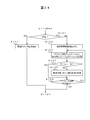
- FIG. 24 is a flowchart showing the function restriction process in the gateway 10. This process is realized by replacing the process S111 of FIG. First, the stop control unit 10055 determines whether or not the flag is "stop", and if it is "stop” (YES in S121), instructs the related ECU to stop (S111). When the flag is not "stop", that is, "function restriction” (NO in S121), the record R41 of the function D of the function restriction information 91 is read (S122).
- the gateway 10 compares the version acquired from the ECU with the version of the function configuration information 61c for each ECU, and confirms the difference (S123). If the gateway 10 determines that the versions match, it does nothing (YES in S124). When the gateway 10 determines that the versions do not match (NO in S124), the gateway 10 limits a part of the function according to the content defined in the restriction content 6037 of the function restriction information 91 (S125). Next, it is determined whether or not there is an ECU that has not compared the gateway 10 versions (S126), and if the comparison of all versions is completed, the process ends (NO in S126). When the gateway 10 determines that there is an ECU whose version has not been compared (NO in S126), it returns to S123 and repeats the process.
- the stop control unit 10055 is a function related to the second verification information determined to be inconsistent, and is a flag.
- the function restriction information 91 is referred to, and it is determined whether or not to restrict the function based on the second identification information whose version information does not match. Therefore, it is possible to operate a useful function even when the table verification information does not match.
- the present invention is not limited to the above-mentioned examples, and includes various modifications.
- the above-described embodiment has been described in detail in order to explain the present invention in an easy-to-understand manner, and is not necessarily limited to those having all the described configurations.
- the functional configuration information management device is the gateway 10, but the communication module 11 and the HMI 12 may be the functional configuration information management device. Further, a dedicated device may be provided.
- the configuration of the functional block is only an example.
- Several functional configurations shown as separate functional blocks may be integrally configured, or the configuration represented by one functional block diagram may be divided into two or more functions. Further, a part of the functions of each functional block may be provided in another functional block.
- Each of the above configurations, functions, processing units, processing means, etc. may be realized by hardware by designing a part or all of them by, for example, an integrated circuit. Further, each of the above configurations, functions, and the like may be realized by software by the processor interpreting and executing software that realizes each function.
- control lines and information lines indicate what is considered necessary for explanation, and not all control lines and information lines are necessarily shown on the product. In practice, it can be considered that almost all configurations are interconnected.
Landscapes
- Engineering & Computer Science (AREA)
- Physics & Mathematics (AREA)
- General Physics & Mathematics (AREA)
- Theoretical Computer Science (AREA)
- General Engineering & Computer Science (AREA)
- Software Systems (AREA)
- Computer Security & Cryptography (AREA)
- Mechanical Engineering (AREA)
- Computer Networks & Wireless Communication (AREA)
- Automation & Control Theory (AREA)
- Human Computer Interaction (AREA)
- Transportation (AREA)
- Signal Processing (AREA)
- Stored Programmes (AREA)
Abstract
演算装置は、複数の電子制御装置と接続され、複数の電子制御装置は、1以上の電子制御装置によりそれぞれの機能を構成し、機能ごとに、機能を構成する1以上の電子制御装置の第1識別情報および第1検証情報を含む機能構成情報を受信する外部通信部と、複数の電子制御装置のそれぞれから、電子制御装置に搭載されたソフトウェアのバージョン情報および電子制御装置の第2識別情報を取得する取得部と、機能ごとに、機能を構成するすべての電子制御装置のバージョン情報であって取得部が取得したバージョン情報および機能を構成するすべての電子制御装置の第2識別情報を用いて第2検証情報を作成する算出部と、機能ごとに、第1検証情報および第2検証情報の整合を判定する判定部とを備える。
Description
本発明は、演算装置、および判定方法に関する。
近年、運転支援機能や自動運転技術の進展により、自動車用の電子制御装置(ECU:Electric Control Unit)に搭載されるソフトウェアの規模が増大している。また、それに伴ってソフトウェア不具合に起因するリコールの回数だけでなく、1回あたりに対応が必要な台数も増加している。そのため、ECUに搭載されるソフトウェアを遠隔で更新する技術へのニーズが高まっている。ソフトウェアの更新が容易になることで、自動車を構成する各機能に対するハードウェアとソフトウェアの構成を管理することが課題となる。特許文献1には、複数の電子制御装置を備えた車両を特定するシステムであって、各車両に搭載された各電子制御装置の識別データ及び各電子制御装置間の接続状況を示す接続データをパターンとして記憶するパターン記憶手段と、任意の車両のパターンを前記パターン記憶手段に記憶されたパターンと照合する照合手段と、を有し、任意の車両のパターンと記憶された前記パターンとの同一性により前記任意の車両を特定することを特徴とする車両特定システムが開示されている。
特許文献1に記載されている発明では、機能ごとの構成情報を確認できない。
本発明の第1の態様による演算装置は、複数の電子制御装置と接続される演算装置であって、前記複数の電子制御装置は、1以上の前記電子制御装置によりそれぞれの機能を構成し、前記機能ごとに、前記機能を構成する1以上の前記電子制御装置の第1識別情報および第1検証情報を含む機能構成情報を受信する外部通信部と、前記複数の電子制御装置のそれぞれから、前記電子制御装置に搭載されたソフトウェアのバージョン情報および前記電子制御装置の第2識別情報を取得する取得部と、前記機能ごとに、前記機能を構成するすべての前記電子制御装置のバージョン情報であって前記取得部が取得したバージョン情報および前記機能を構成するすべての前記電子制御装置の前記第2識別情報を用いて第2検証情報を作成する算出部と、前記機能ごとに、前記第1検証情報および前記第2検証情報の整合を判定する判定部とを備える。
本発明の第2の態様による判定方法は、複数の電子制御装置と接続される演算装置が実行する判定方法であって、前記複数の電子制御装置は、1以上の前記電子制御装置によりそれぞれの機能を構成し、前記機能ごとに、前記機能を構成する1以上の前記電子制御装置の第1識別情報および第1検証情報を受信することと、前記複数の電子制御装置のそれぞれから、前記電子制御装置に搭載されたソフトウェアのバージョン情報および前記電子制御装置の第2識別情報を取得することと、前記機能ごとに、前記機能を構成するすべての前記電子制御装置のバージョン情報であって取得したバージョン情報および前記機能を構成するすべての前記電子制御装置の前記第2識別情報を用いて第2検証情報を作成することと、前記機能ごとに、前記第1検証情報および前記第2検証情報の整合を判定することとを含む。
本発明の第2の態様による判定方法は、複数の電子制御装置と接続される演算装置が実行する判定方法であって、前記複数の電子制御装置は、1以上の前記電子制御装置によりそれぞれの機能を構成し、前記機能ごとに、前記機能を構成する1以上の前記電子制御装置の第1識別情報および第1検証情報を受信することと、前記複数の電子制御装置のそれぞれから、前記電子制御装置に搭載されたソフトウェアのバージョン情報および前記電子制御装置の第2識別情報を取得することと、前記機能ごとに、前記機能を構成するすべての前記電子制御装置のバージョン情報であって取得したバージョン情報および前記機能を構成するすべての前記電子制御装置の前記第2識別情報を用いて第2検証情報を作成することと、前記機能ごとに、前記第1検証情報および前記第2検証情報の整合を判定することとを含む。
本発明によれば、機能ごとの構成情報を確認できる。
―第1の実施の形態―
以下、図1~図13を参照して、本発明に係る演算装置であるゲートウェイの第1の実施の形態に係る機能構成情報管理システムを説明する。
以下、図1~図13を参照して、本発明に係る演算装置であるゲートウェイの第1の実施の形態に係る機能構成情報管理システムを説明する。
(システム構成)
図1は、第1の実施の形態にかかる機能構成情報管理システムSの構成を示す図である。機能構成情報管理システムSは車両1、およびサーバ2を備える。車両1とサーバ2は、アクセスネットワークや拠点を接続するインターネット3、および通信サービスプロバイダが提供するアクセスネットワーク4を介して接続される。
図1は、第1の実施の形態にかかる機能構成情報管理システムSの構成を示す図である。機能構成情報管理システムSは車両1、およびサーバ2を備える。車両1とサーバ2は、アクセスネットワークや拠点を接続するインターネット3、および通信サービスプロバイダが提供するアクセスネットワーク4を介して接続される。
車両1は、ゲートウェイ10、通信モジュール11、Human Machine Interface(HMI)12、および複数のECU(電子制御装置)を備える。ゲートウェイ10、通信モジュール11、およびHMI12は、車内ネットワーク10aにより接続される。
車両1に備えられるECUは特に限定しないが、本実施の形態ではたとえばエンジン制御ECU13、ブレーキ制御ECU14、自動運転ECU15、および先進運転支援システム(ADAS) ECU16を備える。ゲートウェイ10とこれらのECUは、車内ネットワーク10bにより接続される。ゲートウェイ10と接続されるこれらのECUをまとめて、以下では「配下ECU」と呼ぶ。
車内ネットワーク10aおよび車内ネットワーク10bは既知の通信規格、たとえばControl Area Network(CAN)(登録商標)、Local Interconnect Network(LIN)、およびFlexRay、Ethernet(登録商標)のいずれかを採用する。本実施の形態では、車内ネットワーク10bはCANで、車内ネットワーク10aはEthernetで構成される。ただし車内ネットワーク10aおよび車内ネットワーク10bは同一の通信規格を採用してもよい。また、図1では図示しないが、各種ECUなどの車両内の各構成要素は電力線で蓄電池に接続され、電力供給を受けている。
ゲートウェイ10は、配下ECU同士の通信データの中継、配下ECUのソフトウェア更新、および配下ECUに搭載されるソフトウェアの整合性確認を行う。ただし以下では、ソフトウェアの整合性確認を「検証」や「検証処理」とも呼ぶ。なお本実施の形態ではゲートウェイ10はゲートウェイ10自身のソフトウェア更新および整合性確認を行わないが、ゲートウェイ10がゲートウェイ10自身のソフトウェア更新および整合性確認を行ってもよい。なお本実施の形態では、「検証」と「整合」は同じ意味で用いる。
通信モジュール11は、ゲートウェイ10、HMI12、および配下ECUとサーバ2との通信を中継する。HMI12は、車両1の乗員であるユーザへの情報提示やユーザからの入力を受け付けるための装置である。HMI12は、画面表示を行う表示装置および各種スイッチ等の入力装置、またはこれらを組み合わせたタッチパネル等により構成される。エンジン制御ECU13は、エンジンの制御を行う。ブレーキ制御ECU14は、ブレーキの制御を行う。自動運転ECU15は、自動運転時に環境の認識や車両の起動指示等を行う。ADAS ECU16は、自動ブレーキなどの運転支援制御を行う。
サーバ2は機能構成情報61をゲートウェイ10に送信する。ゲートウェイ10は、機能構成情報61に基づいて車両1の機能構成を管理する。
(ゲートウェイのハードウェア構成)
図2は、ゲートウェイ10のハードウェア構成を示すブロック図である。ゲートウェイ10は、マイコン101、FROM(FlashROM)102、CAN用の通信I/F(インタフェース)104、およびEthernet用の通信I/F105を備える。
図2は、ゲートウェイ10のハードウェア構成を示すブロック図である。ゲートウェイ10は、マイコン101、FROM(FlashROM)102、CAN用の通信I/F(インタフェース)104、およびEthernet用の通信I/F105を備える。
マイコン101は、CPU1011、SRAM1012、FROM1013、CAN通信コントローラ1014、およびEther通信コントローラ1015を備える。マイコン101のCPU1011は、FROM1013に格納されるプログラムを実行し、ゲートウェイ10内の他の構成要素を制御するとともに、車内ネットワークにより接続された他の機器とデータ送受信指示を行うなどしてゲートウェイ10を機能させる。ただしCPU1011の代わりにASIC(Application Specific Integrated Circuit)やFPGA(Field Programmable Gate Array)を用いてもよい。
FROM102は、不揮発メモリであり、サーバ2から受信した情報が格納される。CAN通信コントローラ1014は、CAN通信用のインタフェースであり、マイコン101の指示に基づき車内ネットワーク10bを介して、車内ネットワーク10bに接続された配下ECUとの間でデータの送受信を行う。Ether通信コントローラ1015は、Ethernet通信用のインタフェースであり、マイコン101の指示に基づき車内ネットワーク10aを介して、車内ネットワーク10aに接続された機器との間でデータの送受信を行う。
(ECUの構成)
図3は、エンジン制御ECU13のハードウェア構成例を示すブロック図である。ただし本実施の形態においてソフトウェアが更新される対象となるECUはいずれも、少なくとも図3に示すハードウェア構成を備える。エンジン制御ECU13は、マイコン131、およびCAN用の通信I/F133を備える。
図3は、エンジン制御ECU13のハードウェア構成例を示すブロック図である。ただし本実施の形態においてソフトウェアが更新される対象となるECUはいずれも、少なくとも図3に示すハードウェア構成を備える。エンジン制御ECU13は、マイコン131、およびCAN用の通信I/F133を備える。
マイコン131は、CPU1311、SRAM1312、FROM1313、通信コントローラ1314、およびI/Oコントローラ1315を備える。マイコン131は、FROM1313に格納される制御プログラムを実行し、エンジン制御ECU13内の他の構成要素やI/Oを介して接続されたセンサ/アクチュエータ132を制御するとともに、車内ネットワークで接続された他の機器とデータ送受信指示を行うなどしてエンジン制御を実施する。センサ/アクチュエータ132は、マイコン131の指示によってエンジン制御に必要となるデータを取得しつつ、エンジンの制御を実行する。
FROM1313には、FROM1313に格納される制御プログラムのバージョン情報も格納される。またFROM1313にはそのECUの種類や機能を特定する識別情報であるECU IDも格納される。なおECU IDは、「部品番号」や「型番」とも呼ばれる。ECU IDは個々の製品を識別するための、いわゆる製造番号ではなく、ECUの故障時には同一のECU IDを有する別の製品に交換が可能である。
図4は、エンジン制御ECU13上で動作する制御プログラム130の構成を示すブロック図である。ただし本実施の形態においてソフトウェアが更新される対象となるECUはいずれも、少なくとも図4に示す制御プログラム130と同様の構成を備える。
ECU13の機能を実現する制御プログラム130は、マイコン131のFROM1313に格納されCPU1311で実行される。図4では、機能的なまとまりをブロックとして表現しており、各ブロックが複数に分割されてもよいし、いくつかのブロックが統合されてもよい。また制御プログラムは、1つのソフトウェアにより実現されてもよいし、2以上のソフトウェアの組合せにより実現されてもよい。
制御プログラム130は、制御処理部13001、更新制御部13003、情報管理部13004、および通信制御部13005を備える。制御処理部13001は、I/Oコントローラ1315を制御し、センサ/アクチュエータ132を制御してエンジン制御を実施する。停止部130011は、通信制御部13005を介してゲートウェイ10からの停止指令や再開指令を受信し、機能の停止・再開制御を行う。
更新制御部13003は、通信制御部13005を介してゲートウェイ10からの動作指令やソフトウェアの更新に用いるデータを受信しソフトウェアの更新を制御する。情報管理部13004は、FROM1313に格納されるソフトウェアのバージョン情報やECU IDの読み出し、およびソフトウェアの更新に伴うバージョン情報の書き換えを行う。
通信制御部13005は、更新制御部13003等の指示に従って、通信コントローラ1314を制御し、車内ネットワーク10bに接続された機器と通信を行う。通信の際には、CANフレームを解析・構成する。また通信制御部13005は、UDS等の診断通信プロトコルに準拠したコマンドの生成・解析を行う。
(機能と構成)
本実施の形態では、車両1が有する機能はある1つのECUにより、または複数のECUが協業することにより実現される。協業とは、連携して動作することを意味するが、必ずしも各ECUが協業する他のECUを認識する必要はなく、結果的に複数のECUがその機能の実現に関与していればよい。たとえばある機能Xがエンジン制御ECU13と、自動運転ECU15との協業により実現される場合には、本実施の形態では、エンジン制御ECU13および自動運転ECU15が機能Xを「構成する」と言う。また、エンジン制御ECU13および自動運転ECU15が機能Xを「実現する」とも言う。
本実施の形態では、車両1が有する機能はある1つのECUにより、または複数のECUが協業することにより実現される。協業とは、連携して動作することを意味するが、必ずしも各ECUが協業する他のECUを認識する必要はなく、結果的に複数のECUがその機能の実現に関与していればよい。たとえばある機能Xがエンジン制御ECU13と、自動運転ECU15との協業により実現される場合には、本実施の形態では、エンジン制御ECU13および自動運転ECU15が機能Xを「構成する」と言う。また、エンジン制御ECU13および自動運転ECU15が機能Xを「実現する」とも言う。
(サーバの構成)
図5は、サーバ2の構成例を示すブロック図である。サーバ2は、CPU201、主記憶部202、補助記憶部203、通信部204、入力部205、表示部206を備える。CPU201は、補助記憶部203等に蓄積されたサーバ用プログラムを主記憶部202上で実行し機能構成管理情報の登録や配信の制御を行う。補助記憶部203は、機能構成管理情報や車両に配信するECUソフトウェア更新用のデータを記憶する。
図5は、サーバ2の構成例を示すブロック図である。サーバ2は、CPU201、主記憶部202、補助記憶部203、通信部204、入力部205、表示部206を備える。CPU201は、補助記憶部203等に蓄積されたサーバ用プログラムを主記憶部202上で実行し機能構成管理情報の登録や配信の制御を行う。補助記憶部203は、機能構成管理情報や車両に配信するECUソフトウェア更新用のデータを記憶する。
通信部204は、インターネットを介して車両1との間でデータの送受信を行う。入力部205は、サーバ2を操作するオペレータからの操作や入力情報を受け付ける。表示部206は、サーバ2を操作するオペレータに機能構成管理情報登録に関する情報を提供する。
(機能構成管理情報)
図6は、サーバ2で生成され、診断装置5やゲートウェイ10のテーブル管理部10001が管理する機能構成情報61の一例を示す図である。図6(a)は変更前の機能構成情報61である機能構成情報61aを示し、図6(b)は変更後の機能構成情報61である機能構成情報61bを示す。
図6は、サーバ2で生成され、診断装置5やゲートウェイ10のテーブル管理部10001が管理する機能構成情報61の一例を示す図である。図6(a)は変更前の機能構成情報61である機能構成情報61aを示し、図6(b)は変更後の機能構成情報61である機能構成情報61bを示す。
図6では、機能構成情報61をテーブルとして管理し、機能毎の構成情報を記録する場合の例が示されている。機能構成情報61は複数のレコードを有する。機能構成情報61の各レコードは、機能識別ID601、機能識別検証情報602、組み合わせテーブル603、組み合わせテーブル検証情報604、およびフラグ605のフィールドを備える。図6に示す例では、機能構成情報61はR11、R21、およびR31の3つのレコードを有するが、機能構成情報61が有するレコードは1以上であればよく上限はない。また、機能識別検証情報602およびテーブル検証情報604のフィールドはサーバ2のCPU201による演算の結果が格納される。他のフィールドの情報は、オペレータにより入力される。
機能識別ID601は、機能を構成するECUのハードウェアとソフトウェアの組み合わせを識別するための識別情報が格納されるフィールドである。ただしここで言う「ソフトウェア」とはバージョン番号も含んだ概念である。したがって機能識別ID601は、組み合わせテーブル603に登録されたECU IDが変更された場合だけでなく、ソフトウェアのバージョンが変化した場合にも値が変更される。機能識別ID601はたとえば、機能を識別する文字列とECU IDやバージョンの変化に対応する数字の組み合わせである。
機能識別検証情報602は、機能識別ID601の完全性検証情報を格納する領域である。機能識別ID601の完全性検証情報は、たとえば、機能識別ID601のデジタル署名である。
組み合わせテーブル603は、NET ID6031、ECU ID6032、およびソフトウェアバージョン6033から構成される。組み合わせテーブル603には、機能識別ID601が示す機能に関連するECUのハードウェアとソフトウェアの組み合わせの情報が格納される。NET ID6031には、車載ネットワーク上での当該ECUの識別情報を示すIDが格納される。車載ネットワーク10bがCANの場合にはNET ID6031にはCAN IDが格納され、車載ネットワーク10bがEthernetの場合にはIPアドレスやMACアドレスが格納される。NET ID6031にはネットワーク種別や、チャンネル番号など、不図示の情報が含まれてもよい。
ECU ID6032には、ECUの種類や機能を識別するための情報が格納される。ECU ID6032には、たとえばエンジン制御ECU13の種類や機能を示す識別情報である「エンジン」が格納される。ECUの識別情報としては部品番号などが利用されてもよい。すなわちNET ID6031はECUのネットワーク上の識別子であるのに対して、ECU ID6032はECUの種類を示す識別子である。また以下では、NET ID6031を「第1識別情報」と呼ぶことがあり、ECU ID6032を「第2識別情報」と呼ぶことがある。
ソフトウェアバージョン6033は、ECUに搭載されたソフトウェアのバージョンを識別するための情報が格納されるフィールドである。なお以下では、ECU ID6032に格納される情報とソフトウェアバージョン6033に格納される情報とを合わせて「構成情報」とも呼ぶ。
組み合わせテーブル検証情報604は、組み合わせテーブル603に登録された情報の完全性検証情報を格納する領域である。組み合わせテーブル検証情報604は、たとえば、機能識別ID601とECU ID6032、ソフトウェアバージョン6033を連結した値のデジタル署名である。
フラグ605は、組み合わせテーブル603に登録された情報と、配下ECUから収集した情報に矛盾がある場合に、機能識別ID601により示される機能の動作継続を許可するか否かを示す情報が格納される。継続動作を許可する場合には「動作許可」が格納され、動作許可を許容せず停止が必要な場合には「停止」が格納される。
図6(a)のレコードR1は、機能識別IDが”A1”で示される機能Aに関連する情報が格納されたレコードである。レコードR1の機能識別検証情報602のフィールドには「aaa」が格納され、NET ID6031のフィールドには「700」が格納され、ECU ID6032のフィールドにはエンジン制御ECU13であることを示す「エンジン」が格納され、ソフトウェアバージョン6033のフィールドには「1.0.0.0」が格納され、組み合わせテーブル検証情報604のフィールドには「taaa」が格納され、フラグ605のフィールドには、不整合が発生した場合も当該機能の動作継続を許可する「動作許可」が格納されている。
図6(a)のレコードR2は、機能識別IDが”B1”で示される機能Bに関連する情報が格納されたレコードである。レコードR2の機能識別検証情報602のフィールドには「bbb」が格納され、NET ID6031のフィールドには「701」が格納され、ECU ID6032のフィールドにはブレーキ制御ECU14であることを示す「ブレーキ」が格納され、ソフトウェアバージョン6033のフィールドには「1.0.0.0」が格納され、組み合わせテーブル検証情報604のフィールドには「tbbb」が格納され、フラグ605のフィールドには、不整合が発生した場合は当該機能の動作停止が必要であることを示す「停止」が格納されている。
図6(a)のレコードR3は、機能識別IDが”C1”で示される機能Cに関連する情報が格納されたレコードである。レコードR3の機能識別検証情報602のフィールドには「ccc」が格納される。機能Cを構成するECUは3つであるため、NET ID6031のフィールドには「700」「701」「702」がそれぞれ格納され、ECU ID6032のフィールドには「エンジン」「ブレーキ」「ADAS」がそれぞれ格納され、ソフトウェアバージョン6033のフィールドには「1.0.0.0」「1.0.0.0」「1.0.0.0」がそれぞれ格納される。レコードR3の組み合わせテーブル検証情報604のフィールドには「tccc」が格納され、フラグ605のフィールドには、不整合が発生した場合は当該機能の動作停止が必要であることを示す「停止」が格納されている。
なおここでは、機能Cが3つのECUにより構成される例を示したが、前述のように1つの機能がいくつのECUにより構成されてもよく、1つの機能を構成するECUの数に上限はない。
図6(b)は図6(b)に示す機能構成情報61aからエンジン制御ECU13のソフトウェアが更新された場合の更新後の機能構成情報61である機能構成情報61bを示す図である。具体的には図6(b)ではエンジン制御ECU13のソフトウェアバージョンが「1.0.0.0」から「1.0.0.1」に更新された。図6(b)に示すレコードR12、R22、およびR32は、図6(a)に示すレコードR11、R21、およびR31にそれぞれ対応する。
ソフトウェアの更新に伴って、図6(b)のレコードR12およびR32に示すように、ECU ID6032が「エンジン」であるレコードのソフトウェアバージョン6033が「1.0.0.1」に更新されている。また、エンジン制御ECU13を構成要素に含むレコードD101bとレコードD103bの機能の機能識別ID601がそれぞれ”A2”と”C2”に更新されている。このように、機能構成情報においては、機能実現に関連するECUの構成変更に伴い、機能識別IDが更新する必要がある。
(ゲートウェイまたは診断装置のソフトウェア構成)
図7は、ゲートウェイ10で動作するゲートウェイプログラム100の構成を示すブロック図である。
図7は、ゲートウェイ10で動作するゲートウェイプログラム100の構成を示すブロック図である。
ゲートウェイ10の機能を実現するゲートウェイプログラム100は、マイコン101のFROM1013に格納されCPU1011により実行される。図7では、機能的なまとまりをブロックとして表現しており、各ブロックが複数に分割されてもよいし、いくつかのブロックが統合されてもよい。また制御プログラムは、1つのソフトウェアにより実現されてもよいし、2以上のソフトウェアの組合せにより実現されてもよい。
ゲートウェイプログラム100は、制御部10000、テーブル管理部10001、算出判定部10002、取得部10004、停止制御部10005、および通信制御部10006を含む。制御部10000は、テーブル管理部10001、算出判定部10002、取得部10004、停止制御部10005、および通信制御部10006を制御する。テーブル管理部10001は、FROM1013に格納される機能構成情報61を管理する。
算出判定部10002は、取得部10004から取得した構成情報を用いて検証値を算出し、機能構成情報61に含まれるテーブル検証情報604との整合を判定する。算出判定部10002は、判定の結果を停止制御部10005に出力する。検証値の算出方法はサーバ2と同様である。算出判定部10002が検証値の算出に用いる値、すなわちECU IDとソフトウェアのバージョンがサーバ2が算出に用いた値と同じであれば、検証値とテーブル検証情報604は整合する。
取得部10004は、テーブル管理部10001が管理する情報に基づいて、ECUからECU IDやソフトウェアバージョンなどの構成情報を取得し、検証情報算出部に出力する。停止制御部10005は、テーブル管理部10001が管理する動作許可・停止を示すフラグと、算出判定部10002の出力情報に基づいて、不整合が発生した機能の動作継続・停止制御を行う。
通信制御部10006は、停止制御部10005等の指示に従って、CAN通信コントローラ1014およびEther通信コントローラ1015を制御し、車内ネットワーク10aおよび10bに接続された機器と通信を行う。車内ネットワーク10aに接続された機器と通信する際には、通信制御部10007は、TCP/IPやUDP/IPなどのパケットを解析・生成する。また車内ネットワーク10bに接続された機器と通信する際には、通信制御部10006は、CANフレームを解析・生成する。なお通信制御部10006は、通信モジュール11を介して車両1の外部との通信が可能なので、「外部通信部」とも呼べる。
(検証)
図8は、本実施の形態におけるテーブル検証情報604の検証を示す概念図である。図8には以下の説明との対応関係を示すために便宜的にステップ番号を付与している。このステップ番号は後述するフローチャートのステップ番号とは対応しない。
図8は、本実施の形態におけるテーブル検証情報604の検証を示す概念図である。図8には以下の説明との対応関係を示すために便宜的にステップ番号を付与している。このステップ番号は後述するフローチャートのステップ番号とは対応しない。
サーバ2には予め秘密鍵SKが格納され、ゲートウェイ10には予め公開鍵PKが格納されている。サーバ2のCPU201は、あらかじめ定めたルールにしたがって、機能ごとに構成情報を繋げたビット列Xを作成する(S901)。たとえば図6に示したように機能Aを構成するECU「エンジン制御ECU」だけの場合は、機能Aのテーブル検証情報604を作成するために、CPU201は「エンジン」を所定のルールによりたとえばUTF-8の文字コード番号に変換して「0x834712345」を得て、バージョン番号「1.0.0.0」を所定のルールにより変換して「0x1000」を得る。そしてこの2つのビット列を連結して得られる「0x8347123451000」をビット列Xとする。
なお、ある機能が複数のECUから構成される場合には、ビット列Xを作成する際のビット列を並べる順番は、たとえばNET IDが小さい順番に並べるなどのルールがあらかじめ定められている。
そしてCPU201は、そのビット列Xを対象とし、秘密鍵SKを用いてデジタル署名Yを作成する(S902)。作成したデジタル署名Yは、機能構成情報61のテーブル検証情報604として格納され、ゲートウェイ10に送信される。デジタル署名Yの作成方式はあらかじめゲートウェイ10と共有されている。
ゲートウェイ10は、サーバ2から受信した機能構成情報61を参照し、機能ごとにECUから構成情報を読み出し、あらかじめ定めたルールにしたがって検証値であるビット列Zを作成する(S903)。このビット列Zのルールは、サーバ2に格納されているビット列Xの作成ルールと同一である。そしてゲートウェイ10は、機能構成情報61に格納されたテーブル検証情報604、すなわちデジタル署名Yを公開鍵PKを用いて復号化し、ビット列Xを得る(S904)。
念のために記載すると、あらかじめ用意された秘密鍵SKと公開鍵PKの組合せが適切ならば、ゲートウェイ10に接続されているECUの如何にかかわらず、ゲートウェイ10において復号化されて得られるビット列Xはサーバ2において作成されたビット列Xと同一である。最後にゲートウェイ10は、ビット列Xとビット列Zが同一か否かを判断することで検証の合否を判断する(S905)。
ただしビット列Xを用いたデジタル署名Yの作成において、ビット列Xをそのまま用いずにビット列Xのハッシュ値やビット列Xとあらかじめ定めた値とのXOR値に対してデジタル署名Yを作成してもよい。また上述した説明におけるS903とS904は実行の順番を入れ替えてもよいし略同時に実行してもよい。なお以下では、ビット列Zを「検証値」とも呼ぶ。またビット列Zの比較対象は上述した通りビット列Xであるが、以下の説明では冗長な記載を避けるために、単に「ビット列Zとデジタル署名Yの整合を判定する」、または「検証値とテーブル検証情報604の整合を判定する」と記載する。
(車両側画面表示例)
図9は、HMI12に表示される表示画面の一例を示す図である。図9(a)に示す表示G1aは、機能構成情報と実際の構成の不整合が検出されたことをユーザに示す画面例である。不整合により機能を停止させている場合は、さらに本画面に機能停止している旨の情報を表示してもよい。図9(b)に示す表示G1bは、機能構成情報が不整合なため、機能の一部を停止したことをユーザに示す画面例である。
図9は、HMI12に表示される表示画面の一例を示す図である。図9(a)に示す表示G1aは、機能構成情報と実際の構成の不整合が検出されたことをユーザに示す画面例である。不整合により機能を停止させている場合は、さらに本画面に機能停止している旨の情報を表示してもよい。図9(b)に示す表示G1bは、機能構成情報が不整合なため、機能の一部を停止したことをユーザに示す画面例である。
図9(c)に示す表示G1cは、機能構成情報が不整合で対策できないため、回復のためにディーラに連絡することをユーザに促す画面例である。図9(d)に示す表示G1dは、機能構成情報の不整合が回復され、機能の一部が普及したことをユーザに示す画面例である。
(確認シーケンス)
図10は、ゲートウェイ10における検証処理を示すフローチャートである。図10に示す処理は、車両1のイグニッションスイッチがオンにされると実行される。なおゲートウェイ10は、イグニッションスイッチと信号線で接続されてイグニッションスイッチからオン/オフの状態を示す信号を直接受信してもよいし、イグニッションスイッチと接続される不図示のECUから動作指令信号をうけて動作を開始してもよい。
図10は、ゲートウェイ10における検証処理を示すフローチャートである。図10に示す処理は、車両1のイグニッションスイッチがオンにされると実行される。なおゲートウェイ10は、イグニッションスイッチと信号線で接続されてイグニッションスイッチからオン/オフの状態を示す信号を直接受信してもよいし、イグニッションスイッチと接続される不図示のECUから動作指令信号をうけて動作を開始してもよい。
まず制御部10000は、最初に処理対処のレコードxを1に設定する(S101)。機能構成情報61が図6(a)に示すものの場合は、X=1の場合にはレコードR11が読み込まれ、X=2の場合にはレコードR21が読み込まれる。後述するS112の判断により、ゲートウェイプログラム100は、機能構成情報61に格納されたレコードの数だけS103~S111の処理を繰り返す。
制御部10000は、機能構成情報61における処理対象レコードxのNET IDを読み出し、取得部10004にそのNET IDを有するECUからの構成情報の読み出しを指示する(S103)。取得部10004は、通信制御部10006を介して、ECUから構成情報、すなわちECU IDとソフトウェアバージョンの組合せを読み出し、算出判定部10002に読み出した構成情報を渡す(S104)。なお図6(a)に示すレコードR31のようにNET IDが複数存在する場合には、そのすべてのNET IDに対して構成情報を読み出す。算出判定部10002は、受信した構成情報を用いて検証情報を算出する(S105)。
算出判定部10002は、機能構成情報61の処理対処のレコードxにおけるテーブル検証情報604を読みだし、S105において算出した検証値との整合を判断する(S106)。算出判定部10002は、検証値とテーブル検証情報604が整合すると判断する場合は(S107:YES)、S112に進んで制御部10000が未確認のレコード有無を確認する。制御部10000は、未確認のレコードがないと判断する場合は(S112:NO)、確認済みレコードの不整合の有無を確認する。制御部10000は、不整合が全くない、すなわち機能構成情報61の全レコードについて算出判定部10002が算出する検証値と機能構成情報61から読み出したテーブル検証情報604が整合すると判断する場合は(S113:NO)は、処理を終了する。
制御部10000は、不整合がある、すなわち機能構成情報61のいずれかのレコードにおいて算出判定部10002が算出する検証値と機能構成情報61から読み出したテーブル検証情報604が整合しないと判断する場合は(S113:YES)、HMIに図9の画面G1aの表示を指示し(S114)、処理を終了する。未確認のレコードがある場合(S112:YES)は、制御部10000は処理対象レコードxを次のレコードに更新して(S115)、S103に戻る。
制御部10000は、整合しないと判断する場合(S107:NO)、バージョン情報が整合しない旨の故障コード、すなわちDTC(diagnostic trouble code)コードを記録する(S108)。停止制御部10005は、制御部10000から処理対象レコードXと比較結果を受信し、機能構成情報61から該当レコードのフラグ605を読み出す(S109)。停止制御部10005は、読み出したフラグ605が「動作許可」の場合(S110:YES)は、何もせずに処理を継続する。読み出したフラグ605が「動作許可」ではない場合(S110:NO)は、通信制御部10006を介して、機能構成情報61の処理対象レコードXに登録された関連ECUに当該機能の停止を指示する(S111)。以上が図10の説明である。
(不整合時の復旧シーケンス)
図11は、ゲートウェイ10における復旧処理を示すフローチャートである。図11に示す処理は、図10に示す処理の完了後であって、機能構成情報61のいずれかのレコードに不整合がある場合に実行される。ただし図11に示す処理は必ずしも図10に示す処理の完了を待機してから開始しなくてもよく、たとえばS107において否定判断がされた際にS108と並列に実行を開始してもよい。
図11は、ゲートウェイ10における復旧処理を示すフローチャートである。図11に示す処理は、図10に示す処理の完了後であって、機能構成情報61のいずれかのレコードに不整合がある場合に実行される。ただし図11に示す処理は必ずしも図10に示す処理の完了を待機してから開始しなくてもよく、たとえばS107において否定判断がされた際にS108と並列に実行を開始してもよい。
制御部10000は、最初に機能構成情報が不整合である情報を含む構成情報をサーバ2に送信する(S201)。サーバ2は、ゲートウェイ10から受信した構成情報に基づき、次の3つのいずれかの応答を送信する。第1の応答は機能構成情報61の更新指示、第2の応答はECUのソフトウェア更新指示、第3の応答は機能構成情報61およびECUのソフトウェアの更新指示である。サーバ2はたとえば、機能構成情報61の更新日時やECUのソフトウェアの更新日時、ソフトウェアのバージョン番号に基づき第1~第3の応答のいずれにするかを選択する。ただしサーバ2は更新指示を含めない応答を返してもよい。
制御部10000はサーバ2からの応答を受信すると(S202)、その中に更新指示が含まれるかを判定する。制御部10000は、更新指示が含まれないと判断する場合は(S203:NO)、HMI12に図9(c)に示す画面G1cの表示を指示し(S204)、図11に示す処理を終了する。制御部10000は、応答に更新指示が含まれると判断する場合は、サーバ2からの応答に機能構成情報61の更新指示が含まれるかどうかを判定する。制御部10000は、機能構成情報61の更新指示が含まれると判断する場合は(S205:YES)、機能構成情報61を更新する(S206)。
次に制御部10000は、サーバ2からの応答にECUのソフトウェア更新指示が含まれるか否かを判定する。制御部10000は、ECUのソフトウェア更新指示が含まれないと判断する場合は(S207:NO)、機能を停止していたECUに機能復旧を指示し(S209)、HMI12に図9(d)に示す画面G1dの表示を指示(S210)して、図11に示す処理を終了する。制御部10000は、ECUのソフトウェア更新指示が含まれると判断する場合は(S207:YES)、ECUのソフトウェア更新処理を実行(S208)する。そして制御部10000は、ソフトウェア更新が完了すると、機能を停止していたECUに機能復旧を指示し(S209)、HMI12に図9(d)に示す画面G1dの表示を指示(S210)して、図11に示す処理を終了する。
(ソフトウェア更新シーケンス)
図12は、ECUのソフトウェア更新の手順を示すシーケンス図である。なお図12では処理の一例としてエンジン制御ECU13をソフトウェア更新の処理対象として説明するが、以下に説明するシーケンスは処理対象のECUによらず共通である。
図12は、ECUのソフトウェア更新の手順を示すシーケンス図である。なお図12では処理の一例としてエンジン制御ECU13をソフトウェア更新の処理対象として説明するが、以下に説明するシーケンスは処理対象のECUによらず共通である。
ゲートウェイ10は、最初に更新対象であるエンジン制御ECU13からECU IDとソフトウェアバージョンを読み出す(S2081)。ゲートウェイ10は、次に収集したECU IDとソフトウェアバージョン、すなわち構成情報をサーバに送信する(S2082)。サーバ2は、受信した構成情報をもとに、当該車両のソフトウェア更新有無を判断し、その結果としての更新情報をゲートウェイ10に送信する(S2083)。次に、ゲートウェイ10は、サーバ2から更新に必要なデータをダウンロードする(S2084)。更新に必要なデータには、新しいソフトウェアや、更新後の機能構成情報61が含まれる。
次に、ゲートウェイ10は、更新対象のエンジン制御ECU13を制御してエンジン制御ECU13のソフトウェアを更新する(S2085)。ゲートウェイ10は、更新が完了すると機能構成情報61を更新する(S2086)。
なお、図11のS208におけるソフトウェア更新処理では、S2081~S2083は、図11のS201で実施済みのため実施を省略できる。またゲートウェイ10は、ダウンロードしたデータに機能構成情報61が含まれない場合は、S2086は実施しなくてよい。
(サーバ側画面表示例)
図13は、サーバ2における機能構成情報61の登録画面の一例を示す図である。登録画面G2は、サーバ2の表示部206に表示される。機能構成情報61の登録画面G2は、対象機能G21、機能識別ID G22、機能実現ECU G23、不整合時動作G24、登録ボタンG25、および行追加ボタンG26から構成される。
図13は、サーバ2における機能構成情報61の登録画面の一例を示す図である。登録画面G2は、サーバ2の表示部206に表示される。機能構成情報61の登録画面G2は、対象機能G21、機能識別ID G22、機能実現ECU G23、不整合時動作G24、登録ボタンG25、および行追加ボタンG26から構成される。
対象機能G21は、緊急ブレーキ機能などの管理対象の機能を識別する情報を設定する領域であり、本例では符号G21aに示すように「機能C」が設定されている。機能識別ID G22は、管理対象の構成を一意に識別するための識別情報を設定する領域であり、本例では符号G22aに示すように「C1」が設定されている。
関連ECU G23は、対象機能G21を実現するECUを一意に特定するための情報を設定する領域であり、NET ID、ECU ID、ソフトウェアバージョンで構成される。本例では、符号G23a~G23cで示す3つのECUにより機能Cが実現されることが示されている。符号G23aに示すECUは、NET IDが「700」、ECU IDが「エンジン」、ソフトウェアバージョンが「1.0.0.0」である。符号G23bに示すECUは、NET IDが「701」、ECU IDが「ブレーキ」、ソフトウェアバージョンが「1.0.0.0」である。符号G23cに示すECUは、NET IDが「702」、ECU IDが「ADAS」、ソフトウェアバージョンが「1.0.0.0」である。
不整合時動作G24は、対象機能G21に示す機能の構成情報に不整合を検出した場合の当該機能の動作を設定する領域絵であり、本例では符号G24aに示すように「停止」が設定されている。登録ボタンG25は入力した情報をサーバ2に登録するためのボタンであり、オペレータがこのボタンを押すと機能識別検証情報602およびテーブル検証情報604のフィールドの値がCPU201によって算出される。行追加ボタンG26は、機能実現ECUの入力欄を増加させるためのボタンである。
上述した第1の実施の形態によれば、次の作用効果が得られる。
(1)ゲートウェイ10は、複数のECUと接続される。複数のECUのそれぞれは、1以上のECUによりそれぞれの機能を構成する。ゲートウェイ10は、機能ごとに、機能を構成する1以上のECUの第1識別情報、すなわちNET ID6031および第1検証情報、すなわちテーブル検証情報604を含む機能構成情報61を受信する外部通信部、すなわち通信制御部10006と、複数のECUのそれぞれから、ECUに搭載されたソフトウェアバージョン6033およびECUの第2識別情報、すなわちECU ID6032を取得する取得部10004と、機能ごとに、機能を構成するすべてのECUのバージョン情報であって取得部が取得したソフトウェアバージョン6033および機能を構成するすべてのECUの第2識別情報、すなわちECU ID6032を用いて第2検証情報、すなわちビット列Zを算出する算出判定部10002と、機能ごとに、第1検証情報および第2検証情報の整合を判定する算出判定部10002とを備える。そのためゲートウェイ10は、ゲートウェイ10に接続されるECUが構成する全ての機能について、機能ごとの構成情報を確認することができる。
(1)ゲートウェイ10は、複数のECUと接続される。複数のECUのそれぞれは、1以上のECUによりそれぞれの機能を構成する。ゲートウェイ10は、機能ごとに、機能を構成する1以上のECUの第1識別情報、すなわちNET ID6031および第1検証情報、すなわちテーブル検証情報604を含む機能構成情報61を受信する外部通信部、すなわち通信制御部10006と、複数のECUのそれぞれから、ECUに搭載されたソフトウェアバージョン6033およびECUの第2識別情報、すなわちECU ID6032を取得する取得部10004と、機能ごとに、機能を構成するすべてのECUのバージョン情報であって取得部が取得したソフトウェアバージョン6033および機能を構成するすべてのECUの第2識別情報、すなわちECU ID6032を用いて第2検証情報、すなわちビット列Zを算出する算出判定部10002と、機能ごとに、第1検証情報および第2検証情報の整合を判定する算出判定部10002とを備える。そのためゲートウェイ10は、ゲートウェイ10に接続されるECUが構成する全ての機能について、機能ごとの構成情報を確認することができる。
ある機能が複数のECUにより構成される場合には、それら複数のECUに搭載されるソフトウェアのバージョンは、意図された通りの組合せであることが望ましい。たとえば事前に検証されていない組合せでは動作が保証できない場合があるからである。また、ソフトウェアの更新は無線通信を介して実行することも可能なので、専門店に持ち込んでソフトウェアを更新する場合に比べれば、ソフトウェアのバージョンの組合せが予定していないものになる可能性が高まる。また、ECUが故障した際に同一の型番の他のECUと交換し、そのECUのソフトウェアのバージョンが交換前のECUと一致していないことも起こりうる。このような場合に、本実施の形態で示した検証処理を行うことで、機能ごとの構成情報を確認し、問題の発見や問題がないことの確認が可能となる。
(2)第1識別情報とは、ECUのネットワーク上の識別子、すなわちNET ID6031である。第2識別情報とは、ECUの種類を示す識別子、すなわちECU ID6032である。
(3)機能構成情報61には、機能ごとに不整合時の実行を許可または拒否を示すフラグ605が含まれる。停止制御部10005は、算出判定部10002により第1検証情報と第2検証情報とが整合しないと判断されると、整合しないと判定された第2検証情報に関する機能であって、機能構成情報におけるフラグが不整合時に実行を拒否することを示すフラグを有する機能を停止させる。そのためゲートウェイ10は、フラグ605の設定に応じて不整合時に機能を停止させることができる。
(4)制御部10000は、算出判定部10002により第1検証情報と第2検証情報とが整合しないと判断されると、Ether通信コントローラ1015から受ける指令に基づき、機能構成情報61およびECUのソフトウェアの少なくとも一方を更新する。そのためゲートウェイ10は、不整合時に機能構成情報61およびECUのソフトウェアの少なくとも一方を更新できる。
(5)制御部10000は、算出判定部10002により第1検証情報と第2検証情報とが整合しないと判断されると、不整合が生じたことを故障コードとして記憶部であるFROM102に記録する。そのため、FROM102を参照することで不整合の発生を事後的に確認できる。
(6)制御部10000は、算出判定部10002により第1検証情報と第2検証情報とが整合しないと判断されると、不整合が生じたことを表示部、すなわちHMI12に表示させる。そのため車両1の乗員は不整合の発生をHMI12の表示により知ることができる。
(7)ゲートウェイ10は車両1に搭載される。取得部10004、および算出判定部10002は、車両1のイグニッションスイッチがオンにされると動作を開始する。そのため、車両1の起動時に動作することで、車両1が走行を開始する前に、または車両1が低速で走行している間にソフトウェアの不整合を検出できる。
(変形例1)
各機能の構成情報の確認は、ゲートウェイ10以外の装置が実現してもよい。たとえば車両1に接続可能な診断装置により実行してもよい。
各機能の構成情報の確認は、ゲートウェイ10以外の装置が実現してもよい。たとえば車両1に接続可能な診断装置により実行してもよい。
図14は変形例1における機能構成情報管理システムSaの構成を示す図である。図14では、診断装置5が追加されている点が第1の実施の形態と異なる。本変形例では、サーバ2が送信する機能構成情報61は診断装置5が受信する。診断装置5とゲートウェイ10は、OBD2などの汎用コネクタ600を介して接続される。なお図14では通信モジュール11とサーバ2は接続されていないが、ECUのソフトウェアを更新する際には、第1の実施の形態と同様に通信モジュール11はサーバ2と通信を行う。
(診断装置の構成)
図15は、診断装置5の構成例を示すブロック図である。診断装置5は、CPU501、主記憶部502、補助記憶部503、第1通信部504、第2通信部505、入力部506、および表示部507を備える。CPU501は、補助記憶部503等に蓄積されたプログラムを主記憶部502上で実行し機能構成管理の制御を行う。補助記憶部503は、機能構成管理情報や車両に配信するECUソフトウェア更新用のデータを記憶する。
図15は、診断装置5の構成例を示すブロック図である。診断装置5は、CPU501、主記憶部502、補助記憶部503、第1通信部504、第2通信部505、入力部506、および表示部507を備える。CPU501は、補助記憶部503等に蓄積されたプログラムを主記憶部502上で実行し機能構成管理の制御を行う。補助記憶部503は、機能構成管理情報や車両に配信するECUソフトウェア更新用のデータを記憶する。
第1通信部504は、インターネット3を介してサーバ2との間でデータの送受信を行う。第2通信部505は、車両1との間でデータの送受信を行う。入力部506は、診断装置5を操作するオペレータからの操作や入力情報を受け付ける。表示部507は、診断装置5を操作するオペレータに機能構成管理情報を表示する。
(動作)
本変形例では、オペレータが入力部506から動作指示を与えることで図10に示した検証処理が開始される。本変形例ではゲートウェイ10は、診断装置5の動作指令に基づき各ECUとの通信を仲介する。その他の動作は第1の実施の形態と同様である。
本変形例では、オペレータが入力部506から動作指示を与えることで図10に示した検証処理が開始される。本変形例ではゲートウェイ10は、診断装置5の動作指令に基づき各ECUとの通信を仲介する。その他の動作は第1の実施の形態と同様である。
(変形例2)
上述した第1の実施の形態では、機能構成情報61にECU ID6032およびソフトウェアバージョン6033も含まれた。しかしゲートウェイ10は検証処理も含めて特にECU ID6032およびソフトウェアバージョン6033を必要としないので、機能構成情報61にECU ID6032およびソフトウェアバージョン6033を含めなくてもよい。
上述した第1の実施の形態では、機能構成情報61にECU ID6032およびソフトウェアバージョン6033も含まれた。しかしゲートウェイ10は検証処理も含めて特にECU ID6032およびソフトウェアバージョン6033を必要としないので、機能構成情報61にECU ID6032およびソフトウェアバージョン6033を含めなくてもよい。
図16は変形例1における機能構成情報64の一例を示す図である。機能構成情報64では組合せテーブル603がNET ID6031のみで構成される。本変形例においてもゲートウェイ10の動作は第1の実施の形態と同様である。前述のように、第1の実施の形態においてゲートウェイ10は、サーバ2から受信した機能構成情報61に記載されたECU ID6034および機能バージョン6035を参照する機会がなかった。そのため、機能構成情報64からECU ID6034および機能バージョン6035が削除されても何ら影響がないためである。
(変形例3)
上述した第1の実施の形態では、機能構成情報61にNET ID6031およびソフトウェアバージョン6033も含まれた。しかし機能構成情報61にNET ID6031およびソフトウェアバージョン6033を含めなくてもよい。
上述した第1の実施の形態では、機能構成情報61にNET ID6031およびソフトウェアバージョン6033も含まれた。しかし機能構成情報61にNET ID6031およびソフトウェアバージョン6033を含めなくてもよい。
図17は変形例3における機能構成情報65の一例を示す図である。機能構成情報65では組合せテーブル603がECU ID6032のみで構成される。本変形例ではゲートウェイ10の図10のS103~S105を次のように変更する。すなわちゲートウェイ10は、接続されている全てのECUに対してECU IDとソフトウェアのバージョンを問い合わせるメッセージを送信する。そして、機能構成情報65に記載された機能ごとに、取得したECU IDとソフトウェアのバージョンを用いて検証情報、すなわち図8のビット列Zを作成する。
第1の実施の形態ではゲートウェイ10は、機能ごとに機能を構成するECUを特定して問い合わせを行うためにNET ID6031を利用していた。しかし本変形例では機能構成情報65にNET ID6031が含まれないので、接続されているECUの全てに問い合わせを行う。本変形例では、機能構成情報65においてそれぞれの機能を構成するECUはECU ID6032により特定されるので、ゲートウェイ10は問い合わせに対する回答として得られるECU IDとバージョン情報を用いて、機能ごとにビット列Zを作成できる。
(変形例4)
上述した第1の実施の形態では、機能構成情報61にフラグ605が含まれた。しかし機能構成情報61にフラグ605を含めなくてもよい。この場合にはゲートウェイ10は、図10のS110において一律に動作を許可する、または一律に動作を許可しない構成とする。さらにこの場合に、動作を停止させる代わりに機能を制限してもよい。機能の制限とは、処理能力を低下させることや実現する機能の種類を減少させることである。
上述した第1の実施の形態では、機能構成情報61にフラグ605が含まれた。しかし機能構成情報61にフラグ605を含めなくてもよい。この場合にはゲートウェイ10は、図10のS110において一律に動作を許可する、または一律に動作を許可しない構成とする。さらにこの場合に、動作を停止させる代わりに機能を制限してもよい。機能の制限とは、処理能力を低下させることや実現する機能の種類を減少させることである。
本変形例によれば次の作用効果が得られる。
(8)停止制御部10005は、算出判定部10002により第1検証情報と第2検証情報とが整合しないと判断されると、整合しないと判定された第2検証情報に関する機能を停止、または機能を制限させる。そのため、ソフトウェアの不整合が検出された機能を一律に停止、または機能を制限させることができる。
(8)停止制御部10005は、算出判定部10002により第1検証情報と第2検証情報とが整合しないと判断されると、整合しないと判定された第2検証情報に関する機能を停止、または機能を制限させる。そのため、ソフトウェアの不整合が検出された機能を一律に停止、または機能を制限させることができる。
(変形例5)
上述した第1の実施の形態では、公開鍵暗号方式を利用してサーバ2とゲートウェイ10の間で情報の検証を行った。しかし検証の方式は特に限定されず既知の様々な手法に置き換えることや既知の手法を組み合わせることも本発明の範囲に含まれる。たとえば同じ公開鍵暗号方式であっても、サーバ2では秘密鍵SKによる暗号化を行いゲートウェイ10では公開鍵PKによる複合化を行うことで検証を行ってもよい。また公開鍵暗号方式の代わりに対称暗号方式を利用してもよいし、メッセージ認証コードやソルトを利用してもよい。
上述した第1の実施の形態では、公開鍵暗号方式を利用してサーバ2とゲートウェイ10の間で情報の検証を行った。しかし検証の方式は特に限定されず既知の様々な手法に置き換えることや既知の手法を組み合わせることも本発明の範囲に含まれる。たとえば同じ公開鍵暗号方式であっても、サーバ2では秘密鍵SKによる暗号化を行いゲートウェイ10では公開鍵PKによる複合化を行うことで検証を行ってもよい。また公開鍵暗号方式の代わりに対称暗号方式を利用してもよいし、メッセージ認証コードやソルトを利用してもよい。
(変形例6)
サーバ2からのゲートウェイ10への応答に復旧可否フラグを含めてもよい。その場合はゲートウェイ10の制御部10000は、図11のステップS209において、復旧可否フラグにより復旧させてもよい旨のフラグが設定されているECUに対してのみ機能の復旧を指示する。
サーバ2からのゲートウェイ10への応答に復旧可否フラグを含めてもよい。その場合はゲートウェイ10の制御部10000は、図11のステップS209において、復旧可否フラグにより復旧させてもよい旨のフラグが設定されているECUに対してのみ機能の復旧を指示する。
(変形例7)
第1の実施の形態では特に説明しなかったが、ゲートウェイ10は機能識別検証情報602もテーブル検証情報604と同様に検証を行ってもよい。この場合はゲートウェイ10は、たとえば図10のS108の直前に機能識別検証情報602の検証を行い、検証に成功するとS112に進み、検証に失敗するとS108に進む。本変形例によれば、機能識別ID601を検証できる。
第1の実施の形態では特に説明しなかったが、ゲートウェイ10は機能識別検証情報602もテーブル検証情報604と同様に検証を行ってもよい。この場合はゲートウェイ10は、たとえば図10のS108の直前に機能識別検証情報602の検証を行い、検証に成功するとS112に進み、検証に失敗するとS108に進む。本変形例によれば、機能識別ID601を検証できる。
(変形例8)
サーバ2は、テーブル検証情報604の算出に機能識別ID601およびNET ID6031の少なくとも一方をさらに利用してもよい。この場合にはゲートウェイ10も検証処理において同様の算出を行う。
サーバ2は、テーブル検証情報604の算出に機能識別ID601およびNET ID6031の少なくとも一方をさらに利用してもよい。この場合にはゲートウェイ10も検証処理において同様の算出を行う。
(変形例9)
上述した第1の実施の形態では、ゲートウェイ10は車両1のイグニッションスイッチがオンにされると検証処理を開始した。しかしゲートウェイ10は、外部から動作指令を受けて検証処理を開始してもよい。たとえばゲートウェイ10は、通信モジュール11を介して車両1の外部から動作指令を受けてもよいし、車両1に搭載されるECUなどから動作指令を受けて動作を開始してもよい。
上述した第1の実施の形態では、ゲートウェイ10は車両1のイグニッションスイッチがオンにされると検証処理を開始した。しかしゲートウェイ10は、外部から動作指令を受けて検証処理を開始してもよい。たとえばゲートウェイ10は、通信モジュール11を介して車両1の外部から動作指令を受けてもよいし、車両1に搭載されるECUなどから動作指令を受けて動作を開始してもよい。
(変形例10)
上述した第1の実施の形態では、機能構成情報61はオペレータが入力した情報に基づきサーバ2により作成された。しかしあらかじめオペレータが機能構成情報61を作成し、オペレータが機能構成情報61そのものをサーバ2の補助記憶部203に格納してもよい。
上述した第1の実施の形態では、機能構成情報61はオペレータが入力した情報に基づきサーバ2により作成された。しかしあらかじめオペレータが機能構成情報61を作成し、オペレータが機能構成情報61そのものをサーバ2の補助記憶部203に格納してもよい。
―第2の実施の形態―
図18~図19を参照して、本発明に係る演算装置であるゲートウェイの第2の実施の形態を説明する。以下の説明では、第1の実施の形態と同じ構成要素には同じ符号を付して相違点を主に説明する。特に説明しない点については、第1の実施の形態と同じである。本実施の形態では、主に、機能毎にECU内でソフトウェアのバージョンを管理する点で、第1の実施の形態と異なる。また本実施の形態では機能構成情報に格納される情報が第1の実施の形態と異なる。
図18~図19を参照して、本発明に係る演算装置であるゲートウェイの第2の実施の形態を説明する。以下の説明では、第1の実施の形態と同じ構成要素には同じ符号を付して相違点を主に説明する。特に説明しない点については、第1の実施の形態と同じである。本実施の形態では、主に、機能毎にECU内でソフトウェアのバージョンを管理する点で、第1の実施の形態と異なる。また本実施の形態では機能構成情報に格納される情報が第1の実施の形態と異なる。
図18は第2の実施の形態において各ECUに格納される機能別バージョン情報951の一例を示す図である。図18ではエンジン制御ECU13を具体例として使用し、図18(a)はエンジン制御ECU13の更新前の機能別バージョン情報951aを示し、図18(b)はエンジン制御ECU13の更新後の機能別バージョン情報951bを示す。エンジン制御ECU13は、機能Aおよび機能Cの実現に寄与している。そのため、エンジン制御ECU13に保存される機能別バージョン情報951は、図18(a)に示すようにソフトウェアバージョンである「1.0.0.0」と、機能Aバージョンである「1」と、機能Cバージョンである「1」とから構成される。機能別バージョン情報950はソフトウェアの更新に伴い更新される。
図18(b)に示す更新後の機能別バージョン情報951bでは、ソフトウェアバージョンが「1.0.1.0」に更新され、機能Aバージョンが「2」に更新されている。しかし機能Cに関する更新は行われなかったので、機能Cバージョンは「1」から変更がない。
図19は、本実施の形態における機能構成情報62の一例を示す図である。図19(a)は更新前の機能構成情報62aを示す図、図19(b)は更新後の機能構成情報62bを示す図である。図19(a)に示す例ではR41、R51、およびR61のレコードが含まれ、図19(b)に示す例ではR42、R52、およびR62のレコードが含まれる。本実施の形態における機能構成情報62と第1の実施の形態における機能構成情報61とを比較すると、機能構成情報61におけるソフトウェアバージョン6033のフィールドが削除され、その代わりにDID6034と機能バージョン6035のフィールドが追加される。
DID6034には、ECUから機能毎のバージョンを読み出す際に用いる識別情報が格納される。DID6034はバージョン情報の読み出しのために設定された機能の識別情報である。DID6034は、図19に示すように全ECUに共通して機能と1:1で対応してもよいし、ECUごとにDIDと機能との対応を異ならせてもよい。たとえば図19では、レコードR61では3つのECUが共通するDID6034である「F003」により機能Cのバージョン情報が読み出されることが示されている。
図19(a)と図19(b)を比較すると、レコードR41とレコードR42は相違するが、レコードR51およびレコードR61は、レコードR52およびレコードR62と同一である。これは、ソフトウェアのバージョン情報そのものは機能構成情報62に格納せず、各ソフトウェアの各機能のバージョン情報のみを機能構成情報62に格納しているためである。
(その他の相違点)
本実施の形態では、それぞれのECUはゲートウェイ10からDID6034とともにソフトウェアのバージョン情報の問い合わせを受けると、次の動作を行う。すなわちECUは、FROM1313に格納されている機能構成情報62を参照して、受信したDID6034に対応する機能のバージョン情報を返す。
本実施の形態では、それぞれのECUはゲートウェイ10からDID6034とともにソフトウェアのバージョン情報の問い合わせを受けると、次の動作を行う。すなわちECUは、FROM1313に格納されている機能構成情報62を参照して、受信したDID6034に対応する機能のバージョン情報を返す。
ゲートウェイ10は、図10のS104において、機能構成情報62に格納されているNET IDのECUに対してDID6034とともにバージョン情報の問い合わせを行う。たとえばゲートウェイ10は、処理対象レコードX=1の場合には、NET IDが「700」のECUに対して「F001」のDID6034とともにバージョン情報の問い合わせを行う。
本実施の形態では、サーバ2は、ECU ID6032、および機能バージョン6035を用いてビット列Xを作成し、そのデジタル署名であるテーブル検証情報604を作成する。ゲートウェイ10はECU ID6032、および機能バージョン6035を用いてビット列Zを作成し、テーブル検証情報604を検証する。
以上のように、機能毎にECU内で関連するソフトウェア部分のバージョン情報を管理することによって、ソフトウェア更新時の機能構成情報への影響低減を図り、機能構成情報62の変更箇所を減らすことができる。
(第2の実施の形態の変形例)
サーバ2は、ビット列Xの作成においてさらにDID6034の値を用いてもよい。この場合にはゲートウェイ10もビット列Zの作成においてDID6034の値を用いる。
サーバ2は、ビット列Xの作成においてさらにDID6034の値を用いてもよい。この場合にはゲートウェイ10もビット列Zの作成においてDID6034の値を用いる。
―第3の実施の形態―
図20~図21を参照して、本発明に係る演算装置であるゲートウェイの第3の実施の形態を説明する。以下の説明では、第2の実施の形態と同じ構成要素には同じ符号を付して相違点を主に説明する。特に説明しない点については、第2の実施の形態と同じである。本実施の形態では、主に、機能構成情報に格納される情報が第2の実施の形態と異なる。
図20~図21を参照して、本発明に係る演算装置であるゲートウェイの第3の実施の形態を説明する。以下の説明では、第2の実施の形態と同じ構成要素には同じ符号を付して相違点を主に説明する。特に説明しない点については、第2の実施の形態と同じである。本実施の形態では、主に、機能構成情報に格納される情報が第2の実施の形態と異なる。
図20は本実施の形態において各ECUに格納される機能別バージョン情報952の一例を示す図である。図20ではエンジン制御ECU13を具体例として使用し、図20(a)はエンジン制御ECU13の更新前の機能別バージョン情報952aを示し、図20(b)はエンジン制御ECU13の更新後の機能別バージョン情報952bを示す。
機能別バージョン情報952は6バイトで構成され、先頭から、ブートローダ、BSW、ASW、キャリブレーションデータ、機能A、機能Cのそれぞれのソフトウェアのバージョンを一意に識別する情報を示す。機能別バージョン情報952の各桁の値は、それぞれ対象とする部分のソフトウェアの更新にともない更新される。なお図20では説明のために各桁に対応する情報を記載しているが、実際には機能別バージョン情報952には6バイトの値のみから構成される。
図20(a)に示す更新前の機能別バージョン情報952aは、「1,1,1,1,1,1」である。図20(b)に示す更新後の機能別バージョン情報952bは、機能Aに関連する部分が更新されているため、機能Aに該当する識別情報が「2」に更新され、機能Aを含むアプリケーション全体のソフトウェアを示すASWの識別情報が「2」に更新されている。
図21は、本実施の形態における機能構成情報63の一例を示す図である。図21(a)は更新前の機能構成情報63aを示す図、図21(b)は更新後の機能構成情報63bを示す図である。図21(a)に示す例ではR71、R81、およびR91のレコードが含まれ、図21(b)に示す例ではR72、R82、およびR92のレコードが含まれる。本実施の形態における機能構成情報63と第2の実施の形態における機能構成情報62とを比較すると、機能構成情報62におけるDID6034の代わりにマスク6036のフィールドが追加されている。
マスク6036は、当該機能の識別情報が機能別バージョン情報952の先頭から何バイト目に相当するかを示す識別情報である。ゲートウェイ10は、機能別バージョン情報952をECUから読み出したのちにマスク6036を利用することで、読み出した機能別バージョン情報952から、当該機能に関する識別情報を特定する。ただしゲートウェイ10がECUに対してソフトウェアの機能別バージョン情報952の要求とともにマスク6036の値を送信し、ECUが機能別バージョン情報952のうちマスク6036に該当するビットの値だけを返してもよい。
図21(a)と図21(b)とを比較すると、レコードR1とレコードR72は相違するが、レコードR81およびレコードR91は、レコードR82およびレコードR92と同一である。これは、ソフトウェアのバージョン情報そのものは機能構成情報63に格納せず、各ソフトウェアの各機能のバージョン情報のみを機能構成情報63に格納しているためである。
その他の点は第2の実施の形態と同様なので説明を省略する。
以上のように、機能毎にECU内で関連するソフトウェア部分のバージョンを管理することによって、ソフトウェア更新時の機能構成情報への影響低減を図り、不要な変更を減らすことができる。
―第4の実施の形態―
図22~図24を参照して、本発明に係る演算装置であるゲートウェイの第3の実施の形態を説明する。以下の説明では、第2の実施の形態と同じ構成要素には同じ符号を付して相違点を主に説明する。特に説明しない点については、第2の実施の形態と同じである。本実施の形態では、主に、テーブル検証情報が不一致の場合の振る舞いが第1の実施の形態と異なる。
図22~図24を参照して、本発明に係る演算装置であるゲートウェイの第3の実施の形態を説明する。以下の説明では、第2の実施の形態と同じ構成要素には同じ符号を付して相違点を主に説明する。特に説明しない点については、第2の実施の形態と同じである。本実施の形態では、主に、テーブル検証情報が不一致の場合の振る舞いが第1の実施の形態と異なる。
図22は機能Dの機能構成情報61cを示す図、図23は機能Dの機能制限情報91を示す図である。
図22のレコードR4は、機能識別IDが”D2”で示される機能Dに関連する情報が格納されたレコードである。レコードR4の機能識別検証情報602のフィールドには「dzzz」が格納される。機能Dを構成するECUは3つであるため、NET ID6031のフィールドには「701」「702」「703」がそれぞれ格納され、ECU ID6032のフィールドには「ブレーキ」「ADAS」「カメラ」がそれぞれ格納され、ソフトウェアバージョン6033のフィールドには「1.0.0.0」「1.0.0.1」「1.0.0.0」がそれぞれ格納される。レコードR4のテーブル検証情報604のフィールドには「tddd」が格納され、フラグ605のフィールドには、不整合が発生した場合は当該機能の動作制限が必要であることを示す「制限」が格納されている。ここで、当該機能の動作制限とは、機能を停止するのではなく、機能の一部を継続して動作させることをいう。すなわち本実施の形態では、フラグ605のフィールドには、「停止」および「制限」のいずれかが格納され、「動作許可」という値が格納されることはない。
図23は、フラグ605のフィールドが「制限」の場合に参照する機能制限情報91の一例を示す図であり、機能構成情報61cと同様に管理される。図23のレコードR41は、機能Dに関連する機能制限情報が格納されたレコードである。レコードR41の機能600のフィールドには「D」が格納され、機能Dを構成するECUは3つであるため、バージョン不一致ECU ID6038のフィールドには「ブレーキ」「ADAS」「カメラ」がそれぞれ格納され、制限内容6037のフィールドには「警告のみ動作」「機能全停止」「機能全停止」が格納される。
図23に例示した内容について、機能Dが自動ブレーキ機能の場合を例に以下説明する。機能Dの自動ブレーキ機能は、「ブレーキ」「ADAS」「カメラ」のIDを有する3つのECUが連携して機能が実現される。また、自動ブレーキ機能は、ブレーキをかけるべき障害物の検知と障害物が接近した場合のドライバへの警告、ブレーキと3つの基本機能から構成される。本機能構成において、「ブレーキ」ECUのバージョンが不一致の場合は、カメラやADAS ECUは正常に動作できるため、基本機能のうち障害物の検知とドライバへの警告は問題なく実現でき、これらの機能は動作させることが好ましい。一方で、「カメラ」や「ADAS」ECUのバージョンが不一致の場合は、障害物の検知や警告にも問題がある可能性があるため、自動ブレーキ機能の全停止が好ましい。以上により、テーブル検証情報604が不一致の場合でも有用な機能を動作させることが可能になる。
図24は、ゲートウェイ10における機能制限処理を示すフローチャートである。本処理は、図10の処理S111を置き換えることで実現する。まず停止制御部10005は、フラグが「停止」であるか否かを判定し、「停止」の場合(S121のYES)は関連ECUに停止を指示する(S111)。フラグが「停止」でない、すなわち「機能制限」の場合(S121のNO)は、機能制限情報91の機能DのレコードR41を読み出す(S122)。
次にゲートウェイ10はECUごとに、ECUから取得したバージョンと機能構成情報61cのバージョンを比較し、相違を確認する(S123)。ゲートウェイ10は、バージョンが一致すると判断する場合は、何もしない(S124のYES)。ゲートウェイ10は、バージョンが不一致と判断する場合(S124のNO)は、機能制限情報91の制限内容6037に規定された内容に従って、機能の一部を制限する(S125)。次に、ゲートウェイ10バージョンを比較していないECUが存在するか否かを判断し(S126)、すべてのバージョンの比較が完了している場合は処理を終了する(S126のNO)。ゲートウェイ10は、バージョン未比較のECUがあると判断する場合(S126のNO)は、S123に戻って処理を繰り返す。
以上説明した第4の実施の形態では、次の作用効果が得られる。
(9)停止制御部10005は、算出判定部10002により第1検証情報と第2検証情報とが整合しないと判断されると、整合しないと判定された第2検証情報に関する機能であって、フラグが不整合時に実行を許可することを示すフラグを有する機能について、機能制限情報91を参照して、バージョン情報が一致しない第2識別情報に基づき機能を制限するか否かを決定する。そのため、テーブル検証情報が不一致の場合でも有用な機能を動作させることが可能になる。
(9)停止制御部10005は、算出判定部10002により第1検証情報と第2検証情報とが整合しないと判断されると、整合しないと判定された第2検証情報に関する機能であって、フラグが不整合時に実行を許可することを示すフラグを有する機能について、機能制限情報91を参照して、バージョン情報が一致しない第2識別情報に基づき機能を制限するか否かを決定する。そのため、テーブル検証情報が不一致の場合でも有用な機能を動作させることが可能になる。
なお、本発明は上記した実施例に限定されるものではなく、様々な変形例が含まれる。たとえば、上記した実施例は本発明を分かりやすく説明するために詳細に説明したものであり、必ずしも説明した全ての構成を備えるものに限定されるものではない。また、ある実施例の構成の一部を他の実施例の構成に置き換えることが可能であり、また、ある実施例の構成に他の実施例の構成を加えることも可能である。また、各実施例の構成の一部について、他の構成の追加・削除・置換をすることや各処理における処理の順番を入れ替えることも可能である。たとえば、本実施の形態1では機能構成情報管理装置はゲートウェイ10であるとしたが、通信モジュール11やHMI12が機能構成情報管理装置であってもよい。また、専用の装置を設けてもよい。
上述した各実施の形態および変形例において、機能ブロックの構成は一例に過ぎない。別々の機能ブロックとして示したいくつかの機能構成を一体に構成してもよいし、1つの機能ブロック図で表した構成を2以上の機能に分割してもよい。また各機能ブロックが有する機能の一部を他の機能ブロックが備える構成としてもよい。
上記の各構成、機能、処理部、処理手段等は、それらの一部又は全部を、たとえば集積回路で設計する等によりハードウェアで実現してもよい。また、上記の各構成、機能等は、プロセッサがそれぞれの機能を実現するソフトウェアを解釈し、実行することによりソフトウェアで実現してもよい。
また、制御線や情報線は説明上必要と考えられるものを示しており、製品上必ずしも全ての制御線や情報線を示しているとは限らない。実際には殆ど全ての構成が相互に接続されていると考えてもよい。
上記では、種々の実施の形態および変形例を説明したが、本発明はこれらの内容に限定されるものではない。本発明の技術的思想の範囲内で考えられるその他の態様も本発明の範囲内に含まれる。
次の優先権基礎出願の開示内容は引用文としてここに組み込まれる。
日本国特許出願2019-66887(2019年3月29日出願)
日本国特許出願2019-66887(2019年3月29日出願)
1…車両
5…診断装置
6…機能構成情報
10…ゲートウェイ
61、62、63、64、65…機能構成情報
604…テーブル検証情報
605…フラグ
6031…NET ID
6032…ECU ID
10002…算出判定部
10005…停止制御部
5…診断装置
6…機能構成情報
10…ゲートウェイ
61、62、63、64、65…機能構成情報
604…テーブル検証情報
605…フラグ
6031…NET ID
6032…ECU ID
10002…算出判定部
10005…停止制御部
Claims (12)
- 複数の電子制御装置と接続される演算装置であって、
前記複数の電子制御装置は、1以上の前記電子制御装置によりそれぞれの機能を構成し、
前記機能ごとに、前記機能を構成する1以上の前記電子制御装置の第1識別情報および第1検証情報を含む機能構成情報を受信する外部通信部と、
前記複数の電子制御装置のそれぞれから、前記電子制御装置に搭載されたソフトウェアのバージョン情報および前記電子制御装置の第2識別情報を取得する取得部と、
前記機能ごとに、前記機能を構成するすべての前記電子制御装置のバージョン情報であって前記取得部が取得したバージョン情報および前記機能を構成するすべての前記電子制御装置の前記第2識別情報を用いて第2検証情報を算出する算出部と、
前記機能ごとに、前記第1検証情報および前記第2検証情報の整合を判定する判定部とを備える演算装置。 - 請求項1に記載の演算装置において、
前記第1識別情報とは、前記電子制御装置のネットワーク上の識別子であり、
前記第2識別情報とは、前記電子制御装置の種類を示す識別子である演算装置。 - 請求項1に記載の演算装置において、
前記第1識別情報および前記第2識別情報は、前記電子制御装置の種類を示す識別子である演算装置。 - 請求項1に記載の演算装置において、
前記判定部により前記第1検証情報と前記第2検証情報とが整合しないと判断されると、整合しないと判定された前記第2検証情報に関する前記機能を停止または制限させる停止制御部をさらに備える演算装置。 - 請求項1に記載の演算装置において、
前記機能構成情報には、前記機能ごとに不整合時の実行を許可または拒否を示すフラグが含まれ、
前記判定部により前記第1検証情報と前記第2検証情報とが整合しないと判断されると、整合しないと判定された前記第2検証情報に関する前記機能であって、前記機能構成情報における前記フラグが不整合時に実行を拒否することを示すフラグを有する機能を停止させる停止制御部をさらに備える演算装置。 - 請求項5に記載の演算装置において、
前記停止制御部は、前記判定部により前記第1検証情報と前記第2検証情報とが整合しないと判断されると、整合しないと判定された前記第2検証情報に関する前記機能であって、前記フラグが不整合時に実行を許可することを示すフラグを有する機能について、前記バージョン情報が一致しない前記第2識別情報に基づき前記機能を制限するか否かを決定する演算装置。 - 請求項1に記載の演算装置において、
前記判定部により前記第1検証情報と前記第2検証情報とが整合しないと判断されると、前記外部通信部から受ける指令に基づき、前記機能構成情報および前記電子制御装置のソフトウェアの少なくとも一方を更新する更新制御部をさらに備える演算装置。 - 請求項1に記載の演算装置において、
前記判定部により前記第1検証情報と前記第2検証情報とが整合しないと判断されると、不整合が生じたことを記憶部に記録する制御部をさらに備える演算装置。 - 請求項1に記載の演算装置において、
前記判定部により前記第1検証情報と前記第2検証情報とが整合しないと判断されると、不整合が生じたことを表示部に表示させる制御部をさらに備える演算装置。 - 請求項1に記載の演算装置において、
前記演算装置は車両に搭載され、
前記取得部、前記算出部、および前記判定部は、前記車両のイグニッションスイッチがオンにされると動作を開始する演算装置。 - 請求項1に記載の演算装置において、
前記取得部、前記算出部、および前記判定部は、外部から動作指令を受けると動作を開始する演算装置。 - 複数の電子制御装置と接続される演算装置が実行する判定方法であって、
前記複数の電子制御装置は、1以上の前記電子制御装置によりそれぞれの機能を構成し、
前記機能ごとに、前記機能を構成する1以上の前記電子制御装置の第1識別情報および第1検証情報を受信することと、
前記複数の電子制御装置のそれぞれから、前記電子制御装置に搭載されたソフトウェアのバージョン情報および前記電子制御装置の第2識別情報を取得することと、
前記機能ごとに、前記機能を構成するすべての前記電子制御装置のバージョン情報であって取得したバージョン情報および前記機能を構成するすべての前記電子制御装置の前記第2識別情報を用いて第2検証情報を作成することと、
前記機能ごとに、前記第1検証情報および前記第2検証情報の整合を判定することとを含む判定方法。
Priority Applications (2)
| Application Number | Priority Date | Filing Date | Title |
|---|---|---|---|
| US17/433,080 US11928900B2 (en) | 2019-03-29 | 2020-02-21 | Arithmetic operation device and determination method |
| CN202080023945.9A CN113632155B (zh) | 2019-03-29 | 2020-02-21 | 运算装置、判定方法 |
Applications Claiming Priority (2)
| Application Number | Priority Date | Filing Date | Title |
|---|---|---|---|
| JP2019-066887 | 2019-03-29 | ||
| JP2019066887A JP7123843B2 (ja) | 2019-03-29 | 2019-03-29 | 演算装置、判定方法 |
Publications (1)
| Publication Number | Publication Date |
|---|---|
| WO2020202886A1 true WO2020202886A1 (ja) | 2020-10-08 |
Family
ID=72667980
Family Applications (1)
| Application Number | Title | Priority Date | Filing Date |
|---|---|---|---|
| PCT/JP2020/007013 Ceased WO2020202886A1 (ja) | 2019-03-29 | 2020-02-21 | 演算装置、判定方法 |
Country Status (4)
| Country | Link |
|---|---|
| US (1) | US11928900B2 (ja) |
| JP (1) | JP7123843B2 (ja) |
| CN (1) | CN113632155B (ja) |
| WO (1) | WO2020202886A1 (ja) |
Cited By (1)
| Publication number | Priority date | Publication date | Assignee | Title |
|---|---|---|---|---|
| WO2024127841A1 (ja) * | 2022-12-13 | 2024-06-20 | パナソニックIpマネジメント株式会社 | アクセス許可装置、および、アクセス許可方法 |
Families Citing this family (15)
| Publication number | Priority date | Publication date | Assignee | Title |
|---|---|---|---|---|
| JP7003975B2 (ja) * | 2018-08-10 | 2022-01-21 | 株式会社デンソー | 車両情報通信システム,センター装置及びセンター装置のメッセージ送信方法 |
| CN114901450B (zh) * | 2020-02-14 | 2025-11-28 | 住友重机械工业株式会社 | 注射成型机系统、注射成型机 |
| JP7359055B2 (ja) * | 2020-03-26 | 2023-10-11 | 株式会社オートネットワーク技術研究所 | 車載情報処理装置、情報処理方法及びクライアントプログラム |
| JP7512908B2 (ja) * | 2021-01-14 | 2024-07-09 | トヨタ自動車株式会社 | センタ、管理方法および管理プログラム |
| JP7540391B2 (ja) * | 2021-05-13 | 2024-08-27 | トヨタ自動車株式会社 | Otaマスタ、更新制御方法、更新制御プログラム |
| CN118302745A (zh) * | 2021-06-23 | 2024-07-05 | 大众汽车股份公司 | 用于交通工具的软件更新管理 |
| JP7812671B2 (ja) | 2022-01-24 | 2026-02-10 | トヨタ自動車株式会社 | 通信制御装置、車両、通信制御方法及び通信制御プログラム |
| JP7704051B2 (ja) * | 2022-03-09 | 2025-07-08 | 株式会社オートネットワーク技術研究所 | 車載通信装置及び車載通信システム |
| JP7574829B2 (ja) * | 2022-06-22 | 2024-10-29 | トヨタ自動車株式会社 | 制御装置、制御方法および記録媒体 |
| JP7619335B2 (ja) * | 2022-06-30 | 2025-01-22 | トヨタ自動車株式会社 | 電子制御装置、車両制御システム、車両制御方法、及びプログラム |
| JP7737963B2 (ja) * | 2022-07-05 | 2025-09-11 | 株式会社日立製作所 | モジュール情報管理システム及びモジュール情報管理方法。 |
| JP7775789B2 (ja) * | 2022-07-06 | 2025-11-26 | トヨタ自動車株式会社 | Otaマスタ |
| JP7859898B2 (ja) * | 2022-07-19 | 2026-05-15 | Astemo株式会社 | ソフトウェア分析システム、ソフトウェア分析方法 |
| JP2024154731A (ja) * | 2023-04-19 | 2024-10-31 | 株式会社オートネットワーク技術研究所 | 車載装置、プログラム及び、情報処理方法 |
| WO2025048365A1 (ko) * | 2023-08-30 | 2025-03-06 | 현대자동차주식회사 | 차량의 ecu 소프트웨어를 업데이트하기 위한 방법 및 장치 |
Citations (5)
| Publication number | Priority date | Publication date | Assignee | Title |
|---|---|---|---|---|
| JP2009199497A (ja) * | 2008-02-25 | 2009-09-03 | Panasonic Corp | プログラム管理装置、プログラム管理方法及びプログラム管理プログラム |
| WO2015011840A1 (ja) * | 2013-07-26 | 2015-01-29 | 株式会社日立製作所 | 差分データ転送システム及び方法 |
| WO2016147766A1 (ja) * | 2015-03-16 | 2016-09-22 | 日立オートモティブシステムズ株式会社 | ソフト更新装置、ソフト更新方法 |
| JP2016188016A (ja) * | 2015-03-30 | 2016-11-04 | 本田技研工業株式会社 | プログラム書換装置及びプログラム書換方法 |
| JP2018124749A (ja) * | 2017-01-31 | 2018-08-09 | 京セラドキュメントソリューションズ株式会社 | 電子機器、バージョンチェックシステム及びバージョンチェックプログラム |
Family Cites Families (16)
| Publication number | Priority date | Publication date | Assignee | Title |
|---|---|---|---|---|
| JP4004422B2 (ja) | 2003-03-18 | 2007-11-07 | トヨタ自動車株式会社 | 車両特定システム及び車両特定方法 |
| JP2011148398A (ja) * | 2010-01-21 | 2011-08-04 | Denso Corp | 車両用プログラム更新システム |
| US20180081671A1 (en) | 2015-03-30 | 2018-03-22 | Honda Motor Co., Ltd. | Program rewriting device and program rewriting method |
| JP6197000B2 (ja) * | 2015-07-03 | 2017-09-13 | Kddi株式会社 | システム、車両及びソフトウェア配布処理方法 |
| JP6723829B2 (ja) * | 2015-09-14 | 2020-07-15 | パナソニック インテレクチュアル プロパティ コーポレーション オブ アメリカPanasonic Intellectual Property Corporation of America | ゲートウェイ装置、ファームウェア更新方法及び制御プログラム |
| JP6675271B2 (ja) * | 2015-09-14 | 2020-04-01 | パナソニック インテレクチュアル プロパティ コーポレーション オブ アメリカPanasonic Intellectual Property Corporation of America | ゲートウェイ装置、車載ネットワークシステム及びファームウェア更新方法 |
| JP6678548B2 (ja) * | 2015-11-13 | 2020-04-08 | 株式会社東芝 | 中継装置、中継方法およびプログラム |
| JP6609508B2 (ja) * | 2016-04-27 | 2019-11-20 | 日立オートモティブシステムズ株式会社 | 車両用電子制御装置、プログラム更新方法 |
| EP3534257B1 (en) * | 2016-10-28 | 2021-09-15 | Kabushiki Kaisha Toshiba | System for updating software in moving body using vehicle-mounted gateway |
| JP6440334B2 (ja) * | 2017-08-18 | 2018-12-19 | Kddi株式会社 | システム、車両及びソフトウェア配布処理方法 |
| JP2019036238A (ja) * | 2017-08-21 | 2019-03-07 | 株式会社東芝 | 更新制御装置、端末、更新制御方法およびプログラム |
| JP6953947B2 (ja) * | 2017-09-22 | 2021-10-27 | コニカミノルタ株式会社 | 情報処理装置、ファームウェア更新プログラム |
| JP7311245B2 (ja) * | 2018-03-07 | 2023-07-19 | トヨタ自動車株式会社 | マスタ装置、マスタ、制御方法、プログラム及び車両 |
| US11934865B2 (en) * | 2018-06-13 | 2024-03-19 | Hitachi, Ltd. | Vehicle control system for dynamically updating system components |
| KR102529916B1 (ko) * | 2018-09-14 | 2023-05-08 | 현대자동차주식회사 | 가상머신 기반 차량 제어 검증 시스템 및 방법 |
| US11520891B1 (en) * | 2019-12-11 | 2022-12-06 | Amazon Technologies, Inc. | Secure boot of an integrated circuit |
-
2019
- 2019-03-29 JP JP2019066887A patent/JP7123843B2/ja active Active
-
2020
- 2020-02-21 WO PCT/JP2020/007013 patent/WO2020202886A1/ja not_active Ceased
- 2020-02-21 CN CN202080023945.9A patent/CN113632155B/zh active Active
- 2020-02-21 US US17/433,080 patent/US11928900B2/en active Active
Patent Citations (5)
| Publication number | Priority date | Publication date | Assignee | Title |
|---|---|---|---|---|
| JP2009199497A (ja) * | 2008-02-25 | 2009-09-03 | Panasonic Corp | プログラム管理装置、プログラム管理方法及びプログラム管理プログラム |
| WO2015011840A1 (ja) * | 2013-07-26 | 2015-01-29 | 株式会社日立製作所 | 差分データ転送システム及び方法 |
| WO2016147766A1 (ja) * | 2015-03-16 | 2016-09-22 | 日立オートモティブシステムズ株式会社 | ソフト更新装置、ソフト更新方法 |
| JP2016188016A (ja) * | 2015-03-30 | 2016-11-04 | 本田技研工業株式会社 | プログラム書換装置及びプログラム書換方法 |
| JP2018124749A (ja) * | 2017-01-31 | 2018-08-09 | 京セラドキュメントソリューションズ株式会社 | 電子機器、バージョンチェックシステム及びバージョンチェックプログラム |
Cited By (2)
| Publication number | Priority date | Publication date | Assignee | Title |
|---|---|---|---|---|
| WO2024127841A1 (ja) * | 2022-12-13 | 2024-06-20 | パナソニックIpマネジメント株式会社 | アクセス許可装置、および、アクセス許可方法 |
| WO2024127532A1 (ja) * | 2022-12-13 | 2024-06-20 | パナソニックIpマネジメント株式会社 | アクセス許可装置、および、アクセス許可方法 |
Also Published As
| Publication number | Publication date |
|---|---|
| JP2020166583A (ja) | 2020-10-08 |
| CN113632155A (zh) | 2021-11-09 |
| US20220148344A1 (en) | 2022-05-12 |
| US11928900B2 (en) | 2024-03-12 |
| CN113632155B (zh) | 2024-04-12 |
| JP7123843B2 (ja) | 2022-08-23 |
Similar Documents
| Publication | Publication Date | Title |
|---|---|---|
| JP7123843B2 (ja) | 演算装置、判定方法 | |
| JP7816459B2 (ja) | プログラム更新システム、方法、およびプログラム | |
| JP6724717B2 (ja) | 車載機器判定システム | |
| US9126601B2 (en) | Method and system for a vehicle information integrity verification | |
| US20180152341A1 (en) | Gateway device, firmware update method, and recording medium | |
| US20210397433A1 (en) | On-board update device, update processing program, program update method, and on-board update system | |
| CN105635108B (zh) | 具有应用包分类器的防火墙 | |
| JP6036643B2 (ja) | 産業機器生産システム、産業機器生産サーバ、産業機器生産方法、プログラム、及び情報記憶媒体 | |
| CN104571003A (zh) | 工业设备管理系统、工业设备管理服务器、及工业设备管理方法 | |
| US20150066289A1 (en) | Vehicle electronic control unit calibration | |
| US11558404B2 (en) | On-board communication system, switching device, verification method, and verification program | |
| US20200389436A1 (en) | On-vehicle communication device, communication control method, and communication control program | |
| KR102031241B1 (ko) | 블록체인 기반의 분산형 자율 주행 정보 관리 장치 및 방법 | |
| CN113261253A (zh) | 用于控制资源的释放的方法和系统 | |
| DE112005001808T5 (de) | Verfahren und Vorrichtung für das ausfallsichere Schalten einer intelligenten Steuereinrichtung | |
| CN120112907A (zh) | 用于车辆软件的远程证明的数字影子 | |
| US20120179838A1 (en) | Relay server and relay communication system | |
| CN111869165B (zh) | 用于控制和/或监控装置的方法和控制系统 | |
| JP6992611B2 (ja) | 中継装置 | |
| JP6524905B2 (ja) | 電子制御装置 | |
| CN116894235B (zh) | 用于安全执行控制应用程序的方法、系统、主机 | |
| US20120185603A1 (en) | Relay server and relay communication system | |
| JP2009284119A (ja) | フィールドバス通信システム及びデータ管理装置 | |
| JP7083456B2 (ja) | ゲートウェイ装置及び通信方法 | |
| JP7582423B2 (ja) | 制御装置、制御システム及び制御装置の機能又は動作の決定方法 |
Legal Events
| Date | Code | Title | Description |
|---|---|---|---|
| 121 | Ep: the epo has been informed by wipo that ep was designated in this application |
Ref document number: 20785265 Country of ref document: EP Kind code of ref document: A1 |
|
| NENP | Non-entry into the national phase |
Ref country code: DE |
|
| 122 | Ep: pct application non-entry in european phase |
Ref document number: 20785265 Country of ref document: EP Kind code of ref document: A1 |