WO2020196507A1 - 反射型液晶表示装置 - Google Patents
反射型液晶表示装置 Download PDFInfo
- Publication number
- WO2020196507A1 WO2020196507A1 PCT/JP2020/012986 JP2020012986W WO2020196507A1 WO 2020196507 A1 WO2020196507 A1 WO 2020196507A1 JP 2020012986 W JP2020012986 W JP 2020012986W WO 2020196507 A1 WO2020196507 A1 WO 2020196507A1
- Authority
- WO
- WIPO (PCT)
- Prior art keywords
- liquid crystal
- crystal layer
- cholesteric liquid
- group
- layer
- Prior art date
- Legal status (The legal status is an assumption and is not a legal conclusion. Google has not performed a legal analysis and makes no representation as to the accuracy of the status listed.)
- Ceased
Links
Images









Classifications
-
- G—PHYSICS
- G02—OPTICS
- G02B—OPTICAL ELEMENTS, SYSTEMS OR APPARATUS
- G02B5/00—Optical elements other than lenses
-
- G—PHYSICS
- G02—OPTICS
- G02B—OPTICAL ELEMENTS, SYSTEMS OR APPARATUS
- G02B5/00—Optical elements other than lenses
- G02B5/02—Diffusing elements; Afocal elements
-
- G—PHYSICS
- G02—OPTICS
- G02B—OPTICAL ELEMENTS, SYSTEMS OR APPARATUS
- G02B5/00—Optical elements other than lenses
- G02B5/20—Filters
- G02B5/22—Absorbing filters
-
- G—PHYSICS
- G02—OPTICS
- G02B—OPTICAL ELEMENTS, SYSTEMS OR APPARATUS
- G02B5/00—Optical elements other than lenses
- G02B5/30—Polarising elements
-
- G—PHYSICS
- G02—OPTICS
- G02F—OPTICAL DEVICES OR ARRANGEMENTS FOR THE CONTROL OF LIGHT BY MODIFICATION OF THE OPTICAL PROPERTIES OF THE MEDIA OF THE ELEMENTS INVOLVED THEREIN; NON-LINEAR OPTICS; FREQUENCY-CHANGING OF LIGHT; OPTICAL LOGIC ELEMENTS; OPTICAL ANALOGUE/DIGITAL CONVERTERS
- G02F1/00—Devices or arrangements for the control of the intensity, colour, phase, polarisation or direction of light arriving from an independent light source, e.g. switching, gating or modulating; Non-linear optics
- G02F1/01—Devices or arrangements for the control of the intensity, colour, phase, polarisation or direction of light arriving from an independent light source, e.g. switching, gating or modulating; Non-linear optics for the control of the intensity, phase, polarisation or colour
- G02F1/13—Devices or arrangements for the control of the intensity, colour, phase, polarisation or direction of light arriving from an independent light source, e.g. switching, gating or modulating; Non-linear optics for the control of the intensity, phase, polarisation or colour based on liquid crystals, e.g. single liquid crystal display cells
- G02F1/133—Constructional arrangements; Operation of liquid crystal cells; Circuit arrangements
- G02F1/1333—Constructional arrangements; Manufacturing methods
- G02F1/1335—Structural association of cells with optical devices, e.g. polarisers or reflectors
Definitions
- the present invention relates to a reflective liquid crystal display device.
- the cholesteric liquid crystal layer is known as a layer having a property of selectively reflecting either right-handed circularly polarized light or left-handed circularly polarized light in a specific wavelength range. Therefore, it has been developed for various purposes, and is used as a reflective member of an image display device such as a liquid crystal display device, for example.
- Patent Document 1 states, "In an anisotropic optical element having an anisotropic optical property with respect to the normal direction of the element plane, a molecularly oriented cholesteric liquid crystal composed of a polymerizable liquid crystal exhibiting cholesteric regularity.
- the layer has a cholesteric liquid crystal layer formed so as to have a flat layer plane, and the spiral axis main direction defined as the average of the spiral axis directions of the liquid crystal domains in the cholesteric liquid crystal layer is the layer plane.
- An anisotropic optical element characterized in that it is tilted by a predetermined angle with respect to the normal direction.
- Patent Document 2 states that "a first color filter and a predetermined rotation are provided on a surface facing the upper substrate of the lower substrate of the liquid crystal cell in which the liquid crystal is sandwiched between the upper substrate and the lower substrate facing each other.
- a cholesteric liquid crystal layer that reflects a part of the circular polarization having a direction and transmits a part thereof and a second color filter are provided on the lower substrate in this order, and the outer surface side of the upper substrate and the lower substrate
- a liquid crystal display device characterized in that a first polarizing plate and a second polarizing plate are provided on the outer surface side, respectively.
- Patent Document 2 In the reflection mode of the liquid crystal display device of Patent Document 2, the light incident from the upper substrate side passes through the liquid crystal cell and is reflected by the cholesteric liquid crystal layer, and the reflected light passes through the liquid crystal cell and is emitted to the visual recognition side. Display the image by. That is, Patent Document 2 describes that a cholesteric liquid crystal layer is used as a reflective member in a reflective liquid crystal display device.
- the reflective liquid crystal display device due to the structure of the reflective liquid crystal display device, light is reflected even on the surface.
- the reflection of light on the surface is specular.
- the conventional cholesteric liquid crystal layer is specularly reflected. Therefore, the angle of the reflected light reflected on the surface becomes equal to the angle of the reflected light reflected by the reflecting member (cholesteric liquid crystal layer), and the two reflected lights overlap when viewed from the observer side on the display screen.
- the two reflected lights overlap when viewed from the observer side on the display screen.
- it is conceivable to install a film that suppresses reflection on the surface but when an anti-glare film is installed on the surface, the contrast is lowered and the image resolution is lowered.
- the low-reflection film is installed on the surface, there is a problem that the display screen becomes difficult to see due to the reflected light on the surface in the case of a light source having a large amount of light such as sunlight.
- An object of the present invention is to solve such a problem, and to provide a highly visible reflective liquid crystal display device.
- the present invention solves the problem by the following configuration.
- a linear polarizer, a liquid crystal cell, a ⁇ / 4 plate, and a cholesteric liquid crystal layer formed by using a liquid crystal compound are provided in this order.
- the direction of the molecular axis of the liquid crystal compound is changed while continuously rotating along at least one direction in the plane.
- Reflective type in which the arrangement direction of bright and dark parts derived from the cholesteric liquid crystal phase observed by a scanning electron microscope in a cross section perpendicular to the main surface of the cholesteric liquid crystal layer is inclined with respect to the main surface of the cholesteric liquid crystal layer. Liquid crystal display device.
- the cholesteric liquid crystal layer has two or more regions in which the bright and dark portions have different inclination directions.
- the reflective liquid crystal display device according to any one of [1] to [4], which has two or more cholesteric liquid crystal layers having different pitches of bright and dark areas.
- the reflective liquid crystal display device according to any one of [1] to [5], which has a light absorbing layer on the side of the cholesteric liquid crystal layer opposite to the liquid crystal cell.
- the reflective liquid crystal display device according to any one of [1] to [6], which does not have a backlight.
- FIG. 1 It is a figure which conceptually shows an example of the structure of the reflective liquid crystal display device of this invention. It is a figure for demonstrating the operation of the reflective liquid crystal display device shown in FIG. It is a figure for demonstrating the operation of the reflective liquid crystal display device shown in FIG. It is a figure for demonstrating the operation of the conventional reflective liquid crystal display device. It is a figure for demonstrating the operation of the reflective liquid crystal display device shown in FIG. It is a schematic diagram of the XY plane of the cholesteric liquid crystal layer 10. It is a schematic diagram of the XZ plane of the cholesteric liquid crystal layer 10.
- FIG. 5 is a schematic cross-sectional view for explaining an example of an embodiment of a composition layer satisfying condition 1 in step 2-1. It is sectional drawing of the laminated body 50.
- a graph plotting the relationship between the spiral inducing force (HTP: Helical Twisting Power) ( ⁇ m -1 ) ⁇ concentration (mass%) and the light irradiation dose (mJ / cm 2 ) for each of the chiral agent A and the chiral agent B. It is a schematic diagram.
- HTP Helical Twisting Power
- the numerical range represented by using “-” in the present specification means a range including the numerical values before and after “-” as the lower limit value and the upper limit value.
- “(meth) acrylate” is a notation representing both acrylate and methacrylate
- “(meth) acryloyl group” is a notation representing both an acryloyl group and a methacryloyl group.
- “(Meta) acrylic” is a notation that represents both acrylic and methacrylic.
- “identical” shall include an error range generally tolerated in the art.
- “identical” with respect to an angle means that the difference from an exact angle is within a range of less than 5 degrees unless otherwise specified. The difference from the exact angle is preferably less than 4 degrees, more preferably less than 3 degrees.
- the reflective liquid crystal display device of the present invention It has a linear polarizer, a liquid crystal cell, a ⁇ / 4 plate, and a cholesteric liquid crystal layer formed by using a liquid crystal compound in this order. On at least one of the pair of main surfaces of the cholesteric liquid crystal layer, the direction of the molecular axis of the liquid crystal compound is changed while continuously rotating along at least one direction in the plane.
- Reflective type in which the arrangement direction of bright and dark parts derived from the cholesteric liquid crystal phase observed by a scanning electron microscope in a cross section perpendicular to the main surface of the cholesteric liquid crystal layer is inclined with respect to the main surface of the cholesteric liquid crystal layer. It is a liquid crystal display device.
- embodiments of the reflective liquid crystal display device of the present invention will be described with reference to the drawings.
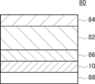
- FIG. 1 shows a diagram conceptually showing an example of the configuration of the reflective liquid crystal display device of the present invention.
- the reflective liquid crystal display device 80 shown in FIG. 1 has a linear polarizing element 84, a liquid crystal cell 82, a ⁇ / 4 plate 86, a cholesteric liquid crystal layer 10, and a light absorbing layer 88 in this order.
- the reflective liquid crystal display device 80 does not have a backlight, and reflects external light incident on the device from the linear polarizer 84 side by the cholesteric liquid crystal layer 10 and transmits the external light through the liquid crystal cell 82 to perform display. It is a type liquid crystal display device.
- the reflective liquid crystal display device of the present invention is not limited to a configuration without a backlight.
- the reflective liquid crystal display device of the present invention has a back light and has a transmission mode in which the light of the backlight is transmitted for display and a reflection mode in which external light is reflected by the cholesteric liquid crystal layer for display.
- the configuration may be switchable.
- the linear polarized light 84 has a polarization axis in one direction and has a function of transmitting specific linearly polarized light.
- a general linear polarizing plate such as an absorption type polarizing plate containing an iodine compound and a reflection type polarizing plate such as a wire grid can be used.
- the polarization axis is synonymous with the transmission axis.
- an iodine-based polarizing plate for example, an iodine-based polarizing plate, a dye-based polarizing plate using a bicolor dye, and a polyene-based polarizing plate can be used.
- Iodine-based polarizing plates and dye-based polarizing plates are generally produced by adsorbing iodine or a dichroic dye on polyvinyl alcohol and stretching the polarizing plate.
- the linear polarizer 84 converts external light into linearly polarized light and causes it to enter the liquid crystal cell.
- Examples of the liquid crystal cell 82 include known liquid crystal image display elements.
- the drive mode of the liquid crystal cell is not particularly limited, and specific examples include various modes such as IPS (In Plane Switching) mode, FFS (Fringe Field Switching) mode, VA (Vertical Alignment) mode, and TN (Twisted Nematic) mode. Modes can be mentioned.
- the liquid crystal cell 82 selects whether to transmit the linearly polarized light transmitted through the linearly polarizing element 84 while maintaining the polarization direction or to transmit the polarization direction by rotating the polarization direction by 90 °, depending on whether the voltage is turned on or off.
- the ⁇ / 4 plate may be composed of only an optically anisotropic layer having a ⁇ / 4 function, or may have a structure in which an optically anisotropic layer having a ⁇ / 4 function is formed on a support. It is good, but when the ⁇ / 4 plate has a support, it is intended that the combination of the support and the optically anisotropic layer is the ⁇ / 4 plate.
- a known ⁇ / 4 plate can be used as the ⁇ / 4 plate 86.
- the ⁇ / 4 plate 86 is made of a material having a reverse dispersion of the double refractive index. As a result, the ⁇ / 4 plate 86 can handle light having a wide band wavelength.
- the ⁇ / 4 plate 86 converts the linearly polarized light transmitted through the liquid crystal cell 82 into circularly polarized light. In addition, the circularly polarized light reflected by the cholesteric liquid crystal layer is converted into linearly polarized light.
- the cholesteric liquid crystal layer 10 is a layer formed by cholesteric orientation of a liquid crystal compound.
- the cholesteric liquid crystal layer 10 has wavelength selective reflectivity and circular polarization selective reflectivity. That is, the cholesteric liquid crystal layer 10 reflects right-circular polarization or left-circular polarization of the selective reflection wavelength, and transmits light in another wavelength region and light in another turning direction.
- the cholesteric liquid crystal layer 10 reflects this circularly polarized light if the turning direction of the circularly polarized light transmitted through the ⁇ / 4 plate 86 is the same as the turning direction of the circularly polarized light reflected by the cholesteric liquid crystal layer 10. Further, the cholesteric liquid crystal layer 10 transmits the circularly polarized light if the turning direction of the circularly polarized light transmitted through the ⁇ / 4 plate 86 is opposite to the turning direction of the circularly polarized light reflected by the cholesteric liquid crystal layer 10.
- the cholesteric liquid crystal layer 10 will be described in detail later.
- the light absorption layer 88 is preferably a layer that the reflective liquid crystal display device of the present invention has.
- the light absorption layer 88 absorbs at least a part of the light having a wavelength transmitted through the cholesteric liquid crystal layer 10. By having the light absorption layer 88, the visibility of the reflected light reflected by the cholesteric liquid crystal layer 10 can be improved.
- the resin may contain a light absorbing material.
- a light absorbing material For example, when the light to be absorbed is visible light, a colored (particularly black) resin material, paper, an inorganic material, or the like can be used as the absorption layer.
- the light absorbing material is not limited, and a known light absorbing material can be used depending on the wavelength range to be absorbed.
- an inorganic pigment such as carbon black or iron black, an organic pigment such as an insoluble azo pigment, or a known light absorber such as a dye such as azo or anthraquinone. it can.
- each layer is shown in a separated state for explanation.
- FIG. 2 the polarization state of the transmitted light after passing through each layer is shown on the left side of each layer.
- the linear polarizer 84 has an absorption axis substantially in the vertical direction in the drawing as shown by the broken line arrow. Therefore, the light transmitted through the linear polarizing element 84 is linearly polarized in the left-right direction in FIG. 2 in the vibration direction.
- the linearly polarized light transmitted through the linearly polarized light 84 is incident on the liquid crystal cell 82.
- the liquid crystal cell 82 is in a state of transmitting the linearly polarized light transmitted through the linearly polarized light 84 while maintaining the polarization direction by turning the voltage on or off. Therefore, the liquid crystal cell 82 transmits light while maintaining the polarized state of the incident linearly polarized light. That is, in the example shown in FIG. 2, the light after passing through the liquid crystal cell 82 is linearly polarized in the left-right direction in FIG.
- the linearly polarized light transmitted through the liquid crystal cell 82 is incident on the ⁇ / 4 plate 86.
- the ⁇ / 4 plate 86 converts the incident linearly polarized light into circularly polarized light.
- the ⁇ / 4 plate 86 converts linearly polarized light in the left-right direction in FIG. 2 into left circularly polarized light. Therefore, the light after passing through the ⁇ / 4 plate 86 is left circularly polarized.
- the left circularly polarized light transmitted through the ⁇ / 4 plate 86 is incident on the cholesteric liquid crystal layer 10.
- the cholesteric liquid crystal layer 10 is a cholesteric liquid crystal layer that reflects right circularly polarized light and transmits left circularly polarized light. Therefore, in the example shown in FIG. 2, the cholesteric liquid crystal layer 10 transmits the left circularly polarized light incident from the ⁇ / 4 plate 86 side.
- the left circularly polarized light transmitted through the cholesteric liquid crystal layer 10 is incident on the light absorption layer 88.
- the light absorption layer 88 absorbs the incident left circular polarization.
- the external light incident from the linear polarizing plate 84 side is not reflected in the reflective liquid crystal display device 80, so that the reflective liquid crystal display device 80 is on the linear polarizing plate 84 side (display surface). Does not emit light to the side). As a result, the reflective liquid crystal display device 80 displays black.
- the polarization state of the transmitted light after passing through each layer is shown on the left side of each layer, and the polarization state of the reflected light after passing through each layer is shown on the right side of each layer.
- the linear polarizer 84 When external light is incident from the linear polarizer 84 side, the light transmitted through the linear polarizer 84 becomes linearly polarized light.
- the linear polarizer 84 has an absorption axis substantially in the vertical direction in the drawing as shown by the broken line arrow. Therefore, the light transmitted through the linear polarizing element 84 is linearly polarized in the left-right direction in FIG.
- the linearly polarized light transmitted through the linearly polarized light 84 is incident on the liquid crystal cell 82.
- the liquid crystal cell 82 is in a state of transmitting the linearly polarized light transmitted through the linearly polarized light 84 by rotating the polarization direction by 90 ° depending on whether the voltage is turned on or off. Therefore, the liquid crystal cell 82 transmits the incident linearly polarized light by rotating the polarization direction by 90 °. That is, in the example shown in FIG. 3, the light after passing through the liquid crystal cell 82 is linearly polarized in the vertical direction in FIG.
- the linearly polarized light transmitted through the liquid crystal cell 82 is incident on the ⁇ / 4 plate 86. Since the ⁇ / 4 plate 86 converts the linearly polarized light in the left-right direction in FIG. 3 into the left circular polarization, the linearly polarized light in the vertical direction in FIG. 3 is converted into the right circular polarization. Therefore, in the example shown in FIG. 3, the light after passing through the ⁇ / 4 plate 86 is right-handed circularly polarized light.
- the right circularly polarized light transmitted through the ⁇ / 4 plate 86 is incident on the cholesteric liquid crystal layer 10.
- the cholesteric liquid crystal layer 10 is a cholesteric liquid crystal layer that reflects right circularly polarized light and transmits left circularly polarized light. Therefore, in the example shown in FIG. 3, the cholesteric liquid crystal layer 10 reflects the right circularly polarized light incident from the ⁇ / 4 plate 86 side.
- the right circularly polarized light reflected by the cholesteric liquid crystal layer 10 is incident on the ⁇ / 4 plate 86. Since the ⁇ / 4 plate 86 converts the linearly polarized light in the vertical direction in FIG. 3 into right circular polarization, the incident right circularly polarized light is converted into linearly polarized light in the vertical direction in FIG.
- the linearly polarized light transmitted through the ⁇ / 4 plate 86 is incident on the liquid crystal cell 82.
- the liquid crystal cell 82 is in a state of transmitting the linearly polarized light transmitted through the linear polarizing element 84 by rotating the polarization direction by 90 ° by turning the voltage on or off. Therefore, the liquid crystal cell 82 transmits the incident linearly polarized light by rotating the polarization direction by 90 °. That is, in the example shown in FIG. 3, the light after passing through the liquid crystal cell 82 is linearly polarized in the left-right direction in FIG.
- the linearly polarized light transmitted through the liquid crystal cell 82 is incident on the linearly polarized light element 84.
- the linear polarizer 84 has an absorption axis substantially in the vertical direction in the drawing. Therefore, the linearly polarized light in the left-right direction passes through the linearly polarized light 84.
- the external light incident from the linear polarizing plate 84 side is reflected by the cholesteric liquid crystal layer 10 in the reflective liquid crystal display 80, and the linear polarizing plate 84 of the reflective liquid crystal display 80. Light is emitted to the side (display surface side). As a result, the reflective liquid crystal display device 80 displays white.
- the reflective liquid crystal display device 80 displays an image by performing the above-mentioned black display or white display for each pixel.
- black display or white display was described in FIGS. 2 and 3, when displaying the halftone between white and black, the twisted state of the light when passing through the liquid crystal cell 82 is changed. Therefore, the amount of light emitted from the linear polarizing plate 84 side (display surface side) of the reflective liquid crystal display device 80 can be adjusted.
- the reflective liquid crystal display device 80 may have a color filter, and color display is performed by performing the above-mentioned white display and black display in the wavelength range corresponding to each color of the color filter for each pixel. Can be done. Further, from the viewpoint of performing color display, the reflective liquid crystal display device 80 has a cholesteric liquid crystal layer having a selective reflection wavelength corresponding to each color, that is, two or more cholesteric liquid crystal layers having different pitches of bright and dark areas. Is preferable.
- a cholesteric liquid crystal layer having a selective reflection wavelength corresponding to a red region having a cholesteric liquid crystal layer having a selective reflection wavelength corresponding to a green region, and a cholesteric liquid crystal layer having a selective reflection wavelength corresponding to a blue region.
- a cholesteric liquid crystal layer having a selective reflection wavelength corresponding to a red region having a cholesteric liquid crystal layer having a selective reflection wavelength corresponding to a green region
- a cholesteric liquid crystal layer having a selective reflection wavelength corresponding to a blue region is preferable.
- the reflective liquid crystal display device in the reflective liquid crystal display device, light is reflected even on the surface due to its structure. That is, as shown in FIG. 4, a part of the external light I 1 incident on the reflective liquid crystal display device passes through the liquid crystal cell or the like and is reflected by the cholesteric liquid crystal layer 200 (reflected light I 1r ). Part of the external light I 2 is reflected on the surface of the reflective liquid crystal display device (reflected light I 2r ).
- the conventional cholesteric liquid crystal layer 200 mirror-reflects light with respect to the surface of the cholesteric liquid crystal layer 200. Therefore, as shown in FIG.
- the traveling direction of the reflected light I 2r reflected on the surface of the reflective liquid crystal display device and the traveling direction of the reflected light I 1r reflected by the cholesteric liquid crystal layer 200 are substantially the same. Therefore, there is a problem that the two reflected lights overlap and the display screen becomes difficult to see when viewed from the observer U side.
- the liquid crystal cell 82 and the cholesteric liquid crystal layer are not shown.
- the direction of the molecular axis of the liquid crystal compound changes while continuously rotating along at least one direction in the plane on at least one of the pair of main planes.
- the arrangement direction of the bright and dark parts derived from the cholesteric liquid crystal phase observed by a scanning electron microscope (SEM) in a cross section perpendicular to the main surface of the cholesteric liquid crystal layer has a liquid crystal orientation pattern. It has a structure that is inclined with respect to the main surface of the.
- the cholesteric liquid crystal layer reflects light with a surface parallel to the bright and dark areas (hereinafter, also referred to as light and dark lines) observed in the SEM cross section as a reflecting surface. Further, the reflection on this reflecting surface is specular reflection. Therefore, the cholesteric liquid crystal layer 10 having a light and dark line inclined with respect to the main surface reflects the incident light at an angle different from the incident angle with respect to the main surface.
- the fact that the cholesteric liquid crystal layer 10 has a property of reflecting incident light at an angle different from the incident angle with respect to the main surface is also referred to as having reflection anisotropy.
- the traveling direction of the reflected light I 1r reflected by the cholesteric liquid crystal layer 10 is different from the traveling direction of the reflected light I 2r reflected on the surface of the reflective liquid crystal display device. ..
- the influence of the reflected light I 2r reflected on the surface of the reflective liquid crystal display device can be reduced and the visibility can be improved.
- cholesteric liquid crystal layer used in the reflective liquid crystal display device of the present invention will be described in detail below. In the present invention, it is sufficient for the cholesteric liquid crystal layer to retain the optical properties of the cholesteric liquid crystal phase in the layer, and the liquid crystal compound in the layer does not have to exhibit liquid crystal properties.
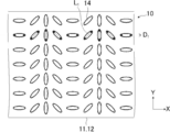
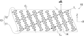
- FIG. 6 and 7 show a schematic diagram conceptually showing the orientation state of the liquid crystal compound in the cholesteric liquid crystal layer.
- FIG. 6 is a schematic view showing the orientation state of the liquid crystal compound in the planes of the main surface 11 and the main surface 12 of the cholesteric liquid crystal layer 10 having a pair of main surfaces 13 composed of the main surface 11 and the main surface 12.
- FIG. 7 is a schematic cross-sectional view showing the state of the cholesteric liquid crystal phase in the cross section perpendicular to the main surface 11 and the main surface 12.
- FIG. 6 corresponds to a schematic view of the XY plane of the cholesteric liquid crystal layer 10
- FIG. 7 corresponds to a schematic view of the XY plane of the cholesteric liquid crystal layer 10.
- the mode of the rod-shaped liquid crystal compound as the liquid crystal compound will be described as an example.
- the liquid crystal compounds 14 are arranged along a plurality of array axes D 1 parallel to each other in the XY plane, and the respective array axes are arranged.
- the orientation of the molecular axis L 1 of the liquid crystal compound 14 has a liquid crystal orientation pattern that changes while continuously rotating in one direction in the plane along the arrangement axis D 1 .
- the array axis D 1 is oriented in the X direction.
- the liquid crystal compounds 14 having the same molecular axis L 1 are oriented at equal intervals.
- the "direction of the molecular axis L 1 of the liquid crystal compound 14 is changed while continuously rotating in one direction in the plane along the array axis D 1" is the molecular axis L 1 of the liquid crystal compound 14 angle between the array axis D 1 is, are different depending on the position of the alignment axis D 1 direction, theta 1 + 180 ° from the angle is theta 1 along the array axis D 1 to the molecular axis L 1 and the array axis D 1 or it means that gradually changes to ⁇ 1 -180 °. That is, a plurality of liquid crystal compounds 14 arranged along the array axis D 1, as shown in FIG.
- molecular axis L 1 is changed while rotating by a predetermined angle along the array axis D 1.
- the molecular axis L 1 of the liquid crystal compound 14 is intended to be the molecular major axis of the rod-shaped liquid crystal compound.
- the molecular axis L 1 of the liquid crystal compound 14 is intended to be an axis parallel to the normal direction of the disk-shaped liquid crystal compound with respect to the disk surface.
- FIG. 7 shows a schematic view of the XX plane of the cholesteric liquid crystal layer 10.
- the molecular axis L 1 of the liquid crystal compound 14 is inclined with respect to the main surface 11 and the main surface 12 (XY plane). ..
- the average angle (average tilt angle) ⁇ 3 formed by the molecular axis L 1 of the liquid crystal compound 14 and the main surface 11 and the main surface 12 (XY plane) is preferably 5 to 45 °, more preferably 12 to 22 °. ..
- the angle ⁇ 3 can be measured by observing the XX plane of the cholesteric liquid crystal layer 10 with a polarizing microscope.
- the molecular axis L 1 of the liquid crystal compound 14 is inclined or oriented in the same direction with respect to the main surface 11 and the main surface 12 (XY plane). Is preferable.
- the average angle is determined by measuring the angle formed by the molecular axis L 1 of the liquid crystal compound 14 and the main surface 11 and the main surface 12 at any five or more points in the polarization microscope observation of the cross section of the cholesteric liquid crystal layer. Is the arithmetic mean value.
- the spiral axis C 1 derived from the cholesteric liquid crystal phase has a main surface 11 and a main surface 12 (XY planes). It is tilted at a predetermined angle with respect to. That is, the reflection surface (plane in which the liquid crystal compounds orthogonal to the spiral axis C 1 and having the same azimuth angle exist) T 1 of the cholesteric liquid crystal layer 10 is substantially relative to the main surface 11 and the main surface 12 (XY planes). It is tilted in a certain direction.
- the "liquid crystal molecules having the same azimuth angle” refer to liquid crystal molecules having the same orientation direction of the molecular axes when projected onto the main surface 11 and the main surface 12 (XY planes).
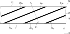
- the arrangement direction P 1 in which the bright portions 15 and the dark portions 16 are alternately arranged as shown in FIG. 8 is the main surface 11 and the main surface 11.
- a striped pattern is observed that is inclined at a predetermined angle ⁇ 2 with respect to the surface 12 (XY surface).
- two bright parts 15 and two dark parts 16 in FIG. 8 correspond to one pitch of the spiral (one winding number of the spiral).
- the molecular axis L 1 of the liquid crystal compound 14 is substantially orthogonal to the arrangement direction P 1 in which the bright portions 15 and the dark portions 16 are alternately arranged.
- the angle formed by the molecular axis L 1 and the arrangement direction P 1 is preferably 80 to 90 °, more preferably 85 to 90 °.
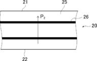
- FIG. 9 shows a schematic cross-sectional view of the conventional cholesteric liquid crystal layer. Specifically, FIG. 9 shows a state of the cholesteric liquid crystal layer in a cross section perpendicular to the main surface 23 of the cholesteric liquid crystal layer 20 having a pair of main surfaces 23 including the main surface 21 and the main surface 22.
- the main surface 21 and the main surface 22 of the cholesteric liquid crystal layer 20 will be referred to as XY planes
- the cross section perpendicular to the XY planes will be described as XY planes. That is, FIG.
- the spiral axis C 2 derived from the cholesteric liquid crystal phase is perpendicular to the main surface 21 and the main surface 22 (XY planes), and the reflective surface T 2 is the main surface 21. And a plane parallel to the main plane 22 (XY plane).
- the molecular axis L 2 of the liquid crystal compound 24 is not inclined with respect to the main surface 21 and the main surface 22 (XY planes). In other words, the molecular axis L 2 is parallel to the main surface 21 and the main surface 22 (XY planes). Therefore, as shown in FIG.
- the arrangement direction P 2 in which the bright portions 25 and the dark portions 26 are alternately arranged is the main surface 21 and the main surface 22. It is perpendicular to (XY plane). Since the cholesteric liquid crystal phase is specularly reflective, for example, when light is incident on the cholesteric liquid crystal layer 20 from an oblique direction, the light is reflected obliquely at a reflection angle of the same angle as the incident angle (in FIG. 9). See arrow). Therefore, as described with reference to FIG.
- the traveling direction of the reflected light I 2r reflected on the surface of the reflective liquid crystal display device and the traveling direction of the reflected light I 1r reflected by the cholesteric liquid crystal layer 200 are approximately one.
- the display screen becomes difficult to see because the two reflected lights overlap.
- the cholesteric liquid crystal layer 10 shown in FIGS. 6 and 7 is reflected because its reflecting surface T 1 is inclined in a predetermined direction with respect to the main surface 11 and the main surface 12 (XY surfaces).
- the traveling direction of the reflected light I 1r reflected by the cholesteric liquid crystal layer 10 is different from the traveling direction of the reflected light I 2r reflected by the surface of the reflective liquid crystal display device.
- the directions are different, and the influence of the reflected light I 2r reflected on the surface of the reflective liquid crystal display device can be reduced to improve the visibility.
- the cholesteric liquid crystal phase is known to exhibit selective reflectivity at specific wavelengths.
- the cholesteric liquid crystal phase exhibits selective reflectivity to either left or right circularly polarized light at a specific wavelength. Whether the reflected light is right-handed or left-handed depends on the twisting direction (sense) of the spiral of the cholesteric liquid crystal phase.
- the selective reflection of circular polarization by the cholesteric liquid crystal phase reflects the right circular polarization when the spiral twisting direction of the cholesteric liquid crystal phase is right, and the left circular polarization when the spiral twisting direction is left.
- the direction of rotation of the cholesteric liquid crystal phase can be adjusted by the type of the liquid crystal compound forming the optically anisotropic layer and / or the type of the chiral agent added.
- ⁇ n can be adjusted by the type of the liquid crystal compound forming the cholesteric liquid crystal layer, the mixing ratio thereof, and the temperature at the time of fixing the orientation.
- the full width at half maximum of the reflection wavelength region is adjusted according to the use of the cholesteric liquid crystal layer, and may be, for example, 10 to 500 nm, preferably 20 to 300 nm, and more preferably 30 to 100 nm.
- the bright portion 15 and the dark portion 16 of the cholesteric liquid crystal layer 10 are configured to be linear, but the present invention is not limited to this, as in the cholesteric liquid crystal layer 30 shown in FIG. ,
- the shape of the light-dark line composed of the bright part 35 and the dark part 36 derived from the cholesteric liquid crystal phase observed by SEM on the XZ plane may be wavy (wavy structure).
- the surfaces parallel to the bright and dark areas are the reflective surfaces. Therefore, by making the shape of the bright part and the dark part derived from the cholesteric liquid crystal phase of the cholesteric liquid crystal layer wavy, the reflective surface becomes wavy. Therefore, the reflection angle of the reflected light on the cholesteric liquid crystal layer 30 differs depending on the position, and light diffusivity can be obtained.
- the shape of the light-dark line consisting of the bright part 35 and the dark part 36 derived from the cholesteric liquid crystal phase of the cholesteric liquid crystal layer 30 is wavy (wavy structure), that the angle formed by the spiral axis and the surface of the cholesteric liquid crystal layer is periodic. It is a layer having a structure that changes to.
- the cholesteric liquid crystal layer 30 is a layer in which the normal of the line formed by the dark portion and the angle formed by the surface of the cholesteric liquid crystal layer in the cross-sectional view observed by SEM change periodically.
- the wavy structure has the following configuration.
- the point where one end of the dark part intersects the main surface or side surface of the cholesteric liquid crystal layer is a1
- the point where the other end of the dark part intersects the main surface or side surface of the cholesteric liquid crystal layer is a2.
- the line segment consisting of the point a2 and the point a2 is used as the reference line. Assuming that the angle formed by the tangent line at a certain point in the dark part and the reference line is the inclination angle of the dark part, the wavy structure has a fluctuation amount of the inclination angle in the linear shape formed by the dark part of 5 ° or more.
- the arrangement of the molecular axis L 3 of the liquid crystal compound 34 on one main surface 31 is shown in the plane as shown in FIG. It is easy to form by orienting so as to face a certain direction.
- the arrangement of the molecular axis L 3 of the liquid crystal compound 34 on the other main surface 32 has the same orientation as the XY plane of the cholesteric liquid crystal layer 10 shown in FIG. Further, the XX plane of the cholesteric liquid crystal layer 30 has the same orientation as the XX plane of the cholesteric liquid crystal layer 10.
- the cholesteric liquid crystal layer 30, the liquid crystal compound 34 is the molecular axis L 3 tilting aligned in a predetermined direction to the principal surface 31 and major surface 32 (X-Y plane), and the helical axis from the cholesteric liquid crystal phase It is inclined at a predetermined angle with respect to the main surface 31 and the main surface 32 (XY surfaces).
- the cholesteric liquid crystal layer 30 in which the bright portion 35 and the dark portion 36 are wavy varies along the arrangement axis by one cycle ⁇ of the length in which the direction of the molecular axis of the liquid crystal compound is rotated by 180 ° in the liquid crystal orientation pattern described later. It can also be formed by making it. Alternatively, as another method, there is also a method of adding a surfactant to the liquid crystal composition for forming the cholesteric liquid crystal layer.
- the liquid crystal compound 14 is obliquely oriented with respect to the main surface 11 and the main surface 12 (XY plane) on the XX plane, and the molecular axis L 1 thereof is inclined.
- the orientation of the molecular axis L 1 of the liquid crystal compound 14 changes while continuously rotating in one direction in the plane along the arrangement axis D 1 . ..
- the cholesteric liquid crystal layer 10 exhibits high linearity in the bright and dark lines composed of the bright and dark parts derived from the cholesteric liquid crystal phase observed by SEM on the XX plane. As a result, it has low haze and high transparency.
- FIG. 13 and 14 show schematic views of another example of the cholesteric liquid crystal layer used in the present invention.
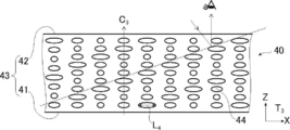
- FIG. 13 conceptually shows the orientation state of the liquid crystal compound on the main surface 41 and the main surface 42 of the cholesteric liquid crystal layer 40 having a pair of main surfaces 43 composed of the main surface 41 and the main surface 42. It is a schematic diagram. Further, FIG.
- FIG. 14 shows the state of the cholesteric liquid crystal layer in a cross section perpendicular to the main surface 43 of the cholesteric liquid crystal layer 40.
- the main surface 41 and the main surface 42 of the cholesteric liquid crystal layer 40 will be referred to as XY planes, and the cross section perpendicular to the XY planes will be described as XY planes. That is, FIG. 14 is a schematic view of the cholesteric liquid crystal layer 40 on the XY plane, and FIG. 14 is a schematic view of the cholesteric liquid crystal layer 40 on the XY plane. As shown in FIG.
- the liquid crystal compounds 44 are arranged along a plurality of array axes D 2 parallel to each other in the XY plane, and the respective array axes are arranged.
- the orientation of the molecular axis L 4 of the liquid crystal compound 44 changes while continuously rotating in one direction in the plane along the array axis D 2 . That is, the orientation state of the liquid crystal compound 44 on the XY plane of the cholesteric liquid crystal layer 40 is the same as the orientation state of the liquid crystal compound 14 on the XY plane of the cholesteric liquid crystal layer 10 shown in FIG.
- the molecular axis L 4 of the liquid crystal compound 44 is not inclined with respect to the main plane 41 and the main plane 42 (XY plane). In other words, the molecular axis L 4 is parallel to the main surface 41 and the main surface 42 (XY planes). Since the cholesteric liquid crystal layer 40 has the XY plane shown in FIG. 13 and the XY plane shown in FIG. 14, the spiral shaft C 3 derived from the cholesteric liquid crystal phase has a main surface 41 and a main surface 42 (X).
- the molecular axis L 1 is arranged in the arrangement direction P 1 in which the bright portions 15 and the dark portions 16 observed by SEM observation on the XZ plane are alternately arranged.
- the direction of the spiral axis C 1 is substantially parallel to the arrangement direction P 1 in which the bright portion 15 and the dark portion 16 are arranged alternately.
- the spiral axis C 3 is perpendicular to the main surface 41 and the main surface 42 (XY surfaces), it spirals with the incident direction of light incident from an oblique direction.
- the angle formed by the direction of the axis C 3 is larger. That is, the incident direction of the light incident from the oblique direction and the direction of the spiral axis C 3 become more non-parallel. Therefore, the cholesteric liquid crystal layer 10 has a higher degree of circular polarization in the reflected light on the reflecting surface than the cholesteric liquid crystal layer 40.
- the orientation of the molecular axis L 1 of the liquid crystal compound 14 is in the plane along the arrangement axis D 1 on both the main surfaces 11 and the main surfaces 12.
- the direction of the molecular axis of the liquid crystal compound continuously rotates in one direction in the plane along the arrangement axis on only one main surface.
- it may be in a changing form.
- the arrangement axis existing on one main surface and the arrangement axis existing on the other main surface are parallel.
- the cholesteric liquid crystal layer may have a form in which a plurality of regions having different intervals between the lines (bright lines) formed by the bright parts derived from the cholesteric liquid crystal phase observed by SEM on the XX plane may exist.
- two bright areas and two dark areas correspond to one spiral pitch. That is, in each region where the distance between the bright lines derived from the cholesteric liquid crystal phase is different from each other, the spiral pitch is different for each region, so that the center wavelength ⁇ of selective reflection is also different.
- the cholesteric liquid crystal layer, region A G, and the blue light wavelength range with a center wavelength of the selective reflection region A R having a center wavelength of the selective reflection to red light wavelength region, green wavelength region A form having a region A B having a central wavelength of selective reflection can be mentioned.
- Regions A R , A G , and A B are carried out by irradiating the main surface with light from an oblique direction (preferably, irradiating light from a direction substantially parallel to the arrangement direction). It can be formed by mask exposure (patterned exposure).
- the cholesteric liquid crystal layer preferably has a region in which the spiral pitch continuously changes in an arbitrary direction in the main surface.
- the regions A R , the regions A G , and the regions A B are continuously arranged in an arbitrary direction in the plane of the main surface.
- the cholesteric liquid crystal layer has a region in which the distance between the lines formed by the bright portions derived from the cholesteric liquid crystal phase observed by SEM on the XX plane is continuously changed.
- the cholesteric liquid crystal layer 10 has a region A R , a region A G , and a region A B , but the present invention is not limited thereto.
- the cholesteric liquid crystal layer may have two or more regions having different selective reflection wavelengths. Further, the center wavelength of selective reflection may be infrared or ultraviolet.
- the above one cycle ⁇ corresponds to the interval between light and dark lines in the reflection polarization microscope observation. Therefore, the coefficient of variation (standard deviation / mean value) of one cycle ⁇ may be calculated by measuring the distance between the light and dark lines in the reflection polarizing microscope observation at 10 points on both main surfaces of the cholesteric liquid crystal layer.
- the cholesteric liquid crystal layer of the present invention has two or more regions on at least one main surface of the cholesteric liquid crystal layer in which the direction of the molecular axis of the liquid crystal compound changes while continuously rotating in the plane.
- it may be configured to reflect light in different directions in two or more regions. That is, it may be configured to have two or more regions having different orientations of the arrangement axes.
- the cholesteric liquid crystal layer may have two or more regions in which the inclination directions of the bright portion and the dark portion are different, and may reflect light in different directions in the two or more regions.
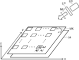
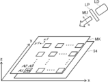
- FIG. 15 shows an example of a configuration having two or more regions having different orientations of the arrangement axes.
- FIG. 15 is a schematic view showing the XY planes of the cholesteric liquid crystal layer.
- the cholesteric liquid crystal layer 60 shown in FIG. 15 has a configuration in which four types of regions A 1 to A 4 having different arrangement axis orientations are arranged in the X direction and the Y direction.
- each of the areas A 1 to A 4 has a substantially square shape, and the area A 2 is arranged on the right side of the area A 1 in the X direction and below the Y direction of the area A 2.
- the area A 3 is arranged, and the area A 4 is arranged on the left side of the area A 3 in the X direction as one set, and this set is arranged in the X direction and the Y direction.
- FIG. 15 Although only 4 ⁇ 4 regions are shown in FIG. 15, a large number of regions A 1 to A 4 are arranged in the plane of the cholesteric liquid crystal layer 60.
- the arrangement directions of the liquid crystal compounds in each region are different.
- the direction of the arrow is the direction in which the inclination of the light / dark line rises when viewed in the XZ cross section, and in the following description, the direction in which the inclination of the light / dark line rises is also arranged in this direction.
- the liquid crystal compound is not shown in FIG. 15, it is the same as the liquid crystal compound 14 shown in FIG. 6 except that the orientation of the arrangement axis is different.
- one arrangement axis (arrow) is shown, but the liquid crystal compounds are arranged along a plurality of arrangement axes parallel to each other in the XY planes of each region.
- the liquid crystal compounds are arranged to the left in the X direction. That is, in the region A 1 , the direction of the molecular axis of the liquid crystal compound changes while continuously rotating in one direction in the plane along the arrangement axis in the X direction. Further, when the region A 1 is viewed in the XX cross section, the inclination of the light and dark lines rises to the left in FIG.
- the liquid crystal compounds are arranged downward in the Y direction. That is, in region A 2 , the direction of the molecular axis of the liquid crystal compound changes while continuously rotating in one direction in the plane along the arrangement axis in the Y direction. Further, when the region A 2 is viewed in the YY cross section, the inclination of the light and dark lines rises in the downward direction in FIG.
- the liquid crystal compounds are arranged to the right in the X direction. That is, in the area A 3, the orientation of the molecular axis of the liquid crystal compound is changed while continuously rotating in one direction in the plane along the array axis in the X direction. Further, when viewed area A 3 by the X-Z cross section, which rises inclined light and dark lines in the right direction in FIG. 15.
- the liquid crystal compounds are arranged upward in the Y direction. That is, in the region A 4 , the direction of the molecular axis of the liquid crystal compound changes while continuously rotating in one direction in the plane along the arrangement axis in the Y direction. Further, when the region A 4 is viewed in the YY cross section, the inclination of the light and dark lines rises in the upward direction in FIG.
- the area A 1 when light from the front direction of the cholesteric liquid crystal layer 60 (the direction perpendicular to the plane of FIG. 15) is incident, the area A 1, the light is reflected in a direction inclined to the X-direction rightward. Further, in the region A 2 , the light is reflected in the direction inclined upward in the Y direction. Further, in the region A 3, the light is reflected in a direction inclined to the X-direction left. Further, in the region A 4 , the light is reflected in the direction inclined downward in the Y direction.
- the cholesteric liquid crystal layer having regions having different directions of the array axes scatter the light incident from one direction in a plurality of directions, so that the viewing angle can be widened. Further, since the cholesteric liquid crystal layer has anisotropy in the reflection direction, both transparency and brightness can be achieved. Further, the viewing angle can be widened in a specific direction by adjusting the arrangement direction (direction of the arrangement axis) of the liquid crystal compound in each region and the inclination angle of the bright part and the dark part.
- the cholesteric liquid crystal layer 60 has a configuration having four types of regions having different arrangement axis directions, but is not limited to this, and two or three types having different arrangement axis directions, Alternatively, the configuration may have five or more types of regions. Further, the cholesteric liquid crystal layer 60 has a configuration in which four types of regions having different arrangement axis directions are arranged in a predetermined pattern, but the present invention is not limited to this, and the arrangement pattern of each region is various arrangement patterns. be able to. Further, the cholesteric liquid crystal layer 60 has a square shape in each region, but the shape is not limited to this, and each region can have various shapes.
- each region of the cholesteric liquid crystal layer 60 has a configuration in which the directions of the array axes are different, but the configuration is not limited to this, the directions of the array axes are the same, and the inclination angles of the bright and dark areas are different. It may have different regions.
- the array axes may be gently connected to each other in the vicinity of the boundary between regions having different directions of the array axes.
- the configuration has a plurality of regions in which the orientation of the arrangement axis is constant, but the present invention is not limited to this, and the orientation of the arrangement axis may be gradually changed in the plane.
- a manufacturing method for manufacturing a cholesteric liquid crystal layer used in the reflective liquid crystal display device of the present invention a predetermined liquid crystal layer is used as an alignment substrate for the cholesteric liquid crystal layer, and the spiral inducing force (HTP) is changed by light irradiation.
- the spiral inducing force examples thereof include a method using a liquid crystal composition containing a chiral agent X or a chiral agent Y whose spiral inducing force changes with a temperature change. The method for producing the cholesteric liquid crystal layer will be described in detail below.
- Step 1 Using a composition containing a disk-shaped liquid crystal compound, a step 1 of forming a liquid crystal layer in which the molecular axis of the disk-shaped liquid crystal compound is inclined with respect to the surface on at least one surface.
- Step 2 It has a step 2 of forming a cholesteric liquid crystal layer on the liquid crystal layer by using a composition containing a liquid crystal compound.
- steps 1 and 2 will be described in detail by taking the above-mentioned cholesteric liquid crystal layer 10 as an example.
- Step 1 is a step of forming a liquid crystal layer using a composition containing a disk-shaped liquid crystal compound.
- the molecular axis of the disk-shaped liquid crystal compound is inclined with respect to the surface.
- the disk-shaped liquid crystal compound is oriented so that its molecular axis is inclined with respect to the surface.
- a cholesteric liquid crystal layer is formed on the inclined oriented surface of the liquid crystal layer having a surface (hereinafter, also referred to as “inclined oriented surface”) in which the disk-shaped liquid crystal compound is inclined oriented.
- step 1 is not particularly limited, and it is preferable to include the following steps 1-1 and the following steps 1-2.
- a method for tilting or aligning the disk-shaped liquid crystal compound a method (step 1-1) of forming a composition layer using a substrate on which a rubbing alignment film having a pretilt angle is arranged on the surface is shown.
- the method for inclining orienting the disk-shaped liquid crystal compound is not limited to this, and may be, for example, a method of adding a surfactant to the composition for forming a liquid crystal layer (for example, step 1-1'below). In this case, in step 1, the following step 1-1'may be performed instead of step 1-1.
- Step 1-1' A step of forming a composition layer on a substrate (a rubbing alignment film may not be arranged on the surface) using a composition containing a disk-shaped liquid crystal compound and a surfactant.
- the composition layer is cured in step 1 as described later.
- Step 1-1 A step of forming a composition layer on a substrate on which a rubbing alignment film having a pretilt angle is arranged on the surface using a composition containing a disk-shaped liquid crystal compound (composition for forming a liquid crystal layer). 2: Step of orienting the disk-shaped compound in the composition layer Step 1 will be described below.
- the substrate is a plate that supports the composition layer described later. Of these, a transparent substrate is preferable.
- the transparent substrate is intended to be a substrate having a visible light transmittance of 60% or more, and the transmittance is preferably 80% or more, more preferably 90% or more.
- the material constituting the substrate is not particularly limited, and for example, cellulose-based polymer, polycarbonate-based polymer, polyester-based polymer, (meth) acrylic-based polymer, styrene-based polymer, polyolefin-based polymer, vinyl chloride-based polymer, amide-based polymer, imide.
- the substrate may contain various additives such as UV (ultraviolet) absorber, matting fine particles, plasticizer, deterioration inhibitor, and release agent.
- the substrate preferably has low birefringence in the visible light region.
- the phase difference of the substrate at a wavelength of 550 nm is preferably 50 nm or less, more preferably 20 nm or less.
- the thickness of the substrate is not particularly limited, but is preferably 10 to 200 ⁇ m, more preferably 20 to 100 ⁇ m from the viewpoint of thinning and handleability.
- the above thickness is intended as an average thickness, and the thickness of any five points on the substrate is measured and calculated and averaged.
- the thickness of the liquid crystal layer and the thickness of the cholesteric liquid crystal layer which will be described later, are also the same.
- the type of rubbing alignment film having a pretilt angle is not particularly limited, but for example, a polyvinyl alcohol alignment film, a polyimide alignment film, or the like can be used.
- the composition for forming a liquid crystal layer contains a disk-shaped liquid crystal compound.
- the disk-shaped liquid crystal compound is not particularly limited, and known compounds can be used, but among them, those having a triphenylene skeleton are preferable.
- the disk-shaped liquid crystal compound may have a polymerizable group.
- the type of the polymerizable group is not particularly limited, and a functional group capable of an addition polymerization reaction is preferable, and a polymerizable ethylenically unsaturated group or a ring-polymerizable group is more preferable.
- a (meth) acryloyl group a vinyl group, a styryl group, an allyl group, an epoxy group, or an oxetane group is preferable, and a (meth) acryloyl group is more preferable.
- the composition for forming a liquid crystal layer may contain a polymerization initiator.
- the composition for forming a liquid crystal layer preferably contains a polymerization initiator.
- the polymerization initiator is preferably a photopolymerization initiator capable of initiating a polymerization reaction by irradiation with ultraviolet rays. Examples of the photopolymerization initiator include ⁇ -carbonyl compounds (described in US Pat. Nos. 2,376,661 and 236,670), acidoin ethers (described in US Pat. No. 2,448,828), and ⁇ -hydrogen-substituted aromatic acidoines.
- the content of the polymerization initiator in the liquid crystal layer forming composition (the total amount when a plurality of types of polymerization initiators are contained) is not particularly limited, but is 0.1 with respect to the total mass of the disk-shaped liquid crystal compound. It is preferably from 20% by mass, more preferably 1.0 to 8.0% by mass.
- the composition for forming a liquid crystal layer may contain a surfactant that may be unevenly distributed on the surface of the composition layer on the substrate side and / or the surface on the side opposite to the substrate.
- a surfactant When the liquid crystal layer forming composition contains a surfactant, the disk-shaped compound is likely to be oriented at a desired inclination angle.
- the surfactant include onium salt compounds (described in JP2012-208397), boronic acid compounds (described in JP2013-542201), and perfluoroalkyl compounds (described in Patent No. 4592225, Neos). (Surfactant, etc.), and polymers containing these functional groups.
- the surfactant may be used alone or in combination of two or more.
- the content of the surfactant in the liquid crystal layer forming composition (the total amount when a plurality of types of surfactants are contained) is not particularly limited, but is 0.01 to 0.01 to the total mass of the disk-shaped compound. 10% by mass is preferable, 0.01 to 5.0% by mass is more preferable, and 0.01 to 2.0% by mass is further preferable.
- the composition for forming a liquid crystal layer may contain a solvent.
- the solvent include water and organic solvents.
- the organic solvent include amides such as N, N-dimethylformamide; sulfoxides such as dimethyl sulfoxide; heterocyclic compounds such as pyridine; hydrocarbons such as benzene and hexane; alkyl halides such as chloroform and dichloromethane.
- Esters such as methyl acetate, butyl acetate, and propylene glycol monoethyl ether acetate; ketones such as acetone, methyl ethyl ketone, cyclohexanone, and cyclopentanone; ethers such as tetrahydrofuran and 1,2-dimethoxyethane; 1, 4-Butandiol diacetate; and the like. These may be used alone or in combination of two or more.
- the composition for forming a liquid crystal layer includes one or more kinds of antioxidants, ultraviolet absorbers, sensitizers, stabilizers, plasticizers, chain transfer agents, polymerization inhibitors, defoamers, leveling agents, etc. It may contain thickeners, flame retardants, surfactants, dispersants, and other additives such as colorants such as dyes and pigments.
- the step of forming the composition layer on the substrate is preferably the step of forming the coating film of the above-mentioned liquid crystal layer forming composition on the substrate.
- the coating method is not particularly limited, and examples thereof include a wire bar coating method, an extrusion coating method, a direct gravure coating method, a reverse gravure coating method, and a die coating method. If necessary, after applying the liquid crystal layer forming composition, a treatment of drying the coating film applied on the substrate may be performed. The solvent can be removed from the coating film by carrying out the drying treatment.
- the film thickness of the coating film is not particularly limited, but is preferably 0.1 to 20 ⁇ m, more preferably 0.2 to 15 ⁇ m, and even more preferably 0.5 to 10 ⁇ m.
- Step 1-2 is preferably a step of orienting the disk-shaped compound in the composition layer by heating the coating film.
- a heating condition it is preferable to heat the composition layer at 40 to 150 ° C. (preferably 60 to 100 ° C.) for 0.5 to 5 minutes (preferably 0.5 to 2 minutes).
- the disk-shaped liquid crystal compound has a polymerizable group
- the method of curing treatment is not particularly limited, and examples thereof include photo-curing treatment and thermosetting treatment. Of these, light irradiation treatment is preferable, and ultraviolet irradiation treatment is more preferable.
- the curing treatment is preferably a polymerization reaction by light irradiation (particularly ultraviolet irradiation), and more preferably a radical polymerization reaction by light irradiation (particularly ultraviolet irradiation).
- a light source such as an ultraviolet lamp is used for ultraviolet irradiation.
- the amount of ultraviolet irradiation energy is not particularly limited, but is generally preferably about 100 to 800 mJ / cm 2 .
- the time for irradiating with ultraviolet rays is not particularly limited, but may be appropriately determined from the viewpoints of both sufficient strength and productivity of the obtained layer.
- the average inclination angle (average tilt angle) of the disk-shaped liquid crystal compound with respect to the surface of the liquid crystal layer is preferably, for example, 20 to 90 °, and is preferably 20 to 80 °. Is more preferable, 30 to 80 ° is further preferable, and 30 to 65 ° is further preferable.
- the average inclination angle was obtained by measuring the angle formed by the molecular axis of the disk-shaped liquid crystal compound and the surface of the liquid crystal layer at any five or more points in the observation of the cross section of the liquid crystal layer with a polarizing microscope, and arithmetically averaging them.
- the average inclination angle of the disk-shaped liquid crystal compound with respect to the surface of the liquid crystal layer on the inclined alignment plane of the liquid crystal layer can be measured by observing the cross section of the liquid crystal layer with a polarizing microscope.
- the inclined alignment surface of the liquid crystal layer has an azimuth angle regulating force of, for example, 0.00030 J / m 2 or less, preferably less than 0.00020 J / m 2 , preferably 0.00010 J / m 2 or less. Is more preferable, and 0.00005 J / m 2 or less is further preferable.
- the lower limit is not particularly limited, but is, for example, 0.00000 J / m 2 or more.
- the azimuth-regulating force of the liquid crystal layer on the inclined orientation plane can be measured by the method described in J. Appl. Phys. 1992, 33, L1242.
- the direction of the molecular axis of the liquid crystal compound continuously rotates in one direction in the plane on the main surface of the cholesteric liquid crystal layer. It becomes easy to change. That is, taking the above-mentioned cholesteric liquid crystal layer 10 (see FIGS. 6 and 7) as an example, the liquid crystal compound 14 is formed on the XY planes by adjusting the azimuth angle restricting force on the inclined alignment plane of the liquid crystal layer.
- Step 2 is a step of forming a cholesteric liquid crystal layer on the liquid crystal layer by using a composition containing a liquid crystal compound. The step 2 will be described below.
- Step 2 preferably has the following step 2-1 and the following step 2-2.
- Step 2-1 Step of forming a composition layer satisfying the following condition 1 or the following condition 2 on the liquid crystal layer formed in step 1.
- Condition 1 At least a part of the liquid crystal compound in the composition layer is on the surface of the composition layer. On the other hand, the liquid crystal compound is inclined or oriented.
- Condition 2 The liquid crystal compound is oriented so that the tilt angle of the liquid crystal compound in the composition layer continuously changes along the thickness direction.
- Step 2-2 A step of forming a cholesteric liquid crystal layer by carrying out a treatment for cholesteric alignment of the liquid crystal compound in the composition layer. The steps 2-1 and 2-2 will be described below.
- FIG. 16 shows a schematic cross-sectional view of a composition layer satisfying condition 1 obtained in step 2-1.
- the liquid crystal compound 14 shown in FIG. 16 is a rod-shaped liquid crystal compound.
- the composition layer 100 is formed on the liquid crystal layer 102 formed by using the disk-shaped liquid crystal compound.
- the liquid crystal layer 102 has an inclined orientation surface 102a on the surface on the side in contact with the composition layer 100 in which the molecular axis of the disk-shaped liquid crystal compound is inclined with respect to the surface of the liquid crystal layer 102 (see FIG. 17).
- the liquid crystal compound 14 is loosely oriented by the inclined alignment surface 102a, so that the liquid crystal compound 14 is loosely oriented with respect to the inclined alignment surface 102a. Orients to tilt.
- the liquid crystal compound 14 is in a certain direction (uniaxial direction) so that the molecular axis L 1 of the liquid crystal compound 14 has a predetermined angle ⁇ 10 with respect to the surface of the composition layer 100. Oriented.
- the liquid crystal compound 14 is oriented so that the molecular axis L 1 is at a predetermined angle ⁇ 10 with respect to the inclined alignment surface 102 a over the entire area of the composition layer 100 in the thickness direction R 1.
- the composition layer satisfying the condition 1 obtained in step 2-1 it is sufficient that a part of the liquid crystal compound 14 is obliquely oriented, and the inclined alignment surface 102a side of the composition layer 100 is shown.
- the liquid crystal compound 14 is composed of at least one of the surface (corresponding to the region A in FIG. 16) and the surface of the composition layer 100 opposite to the inclined orientation surface 102a side (corresponding to the region B in FIG. 16).
- the molecular axis L 1 is oriented at a predetermined angle ⁇ 10 with respect to the surface of the material layer 100, and the liquid crystal compound 14 is placed on the surface of the composition layer 100 on the surface on the inclined orientation surface 102a side.
- the molecular axis L 1 is obliquely oriented so as to have a predetermined angle ⁇ 10 .
- the liquid crystal compound 14 is oriented so that the molecular axis L 1 has a predetermined angle ⁇ 10 with respect to the surface of the composition layer 100 in at least one of the region A and the region B, the following step 2
- the cholesteric orientation of the liquid crystal compound 14 in the other region is caused by the orientation regulating force based on the oriented liquid crystal compound 14 in the region A and / or the region B. Can be induced.
- the composition layer satisfying the above condition 2 corresponds to the composition layer 100 shown in FIG. 16 in which the liquid crystal compound 14 is hybrid-oriented with respect to the surface of the composition layer 100. .. That is, in the above description of FIG. 16, it corresponds to a mode in which the angle ⁇ 10 continuously changes in the thickness direction.
- the liquid crystal compound 14 has a tilt angle ⁇ 20 (angle of the molecular axis L 1 with respect to the surface of the composition layer 100) that continuously changes along the thickness direction R 1 of the composition layer 100. Orientate.
- the composition layer satisfying the condition 2 obtained in step 2-1 it is sufficient that a part of the liquid crystal compound 14 is hybrid-oriented, and the surface of the composition layer 100 on the inclined orientation surface 102a side (in FIG.
- the liquid crystal compound 14 relates to the inclined alignment surface 102a on at least one of the surface (corresponding to the region A) and the surface of the composition layer 100 opposite to the inclined orientation surface 102a side (corresponding to the region B in FIG. 16).
- the hybrid orientation is preferable, and the liquid crystal compound 14 is more preferably hybrid-oriented with respect to the surface of the composition layer 100 on the surface on the inclined alignment surface 102a side.
- the angles ⁇ 10 and ⁇ 20 are not particularly limited unless they are 0 ° in the entire composition layer (when the angle ⁇ 10 is 0 ° in the entire composition layer, the molecular axis L 1 of the liquid crystal compound 14 is a liquid crystal. When the compound 14 is a rod-shaped liquid crystal compound, it is parallel to the inclined orientation plane 102a). In other words, it does not prevent the angles ⁇ 10 and ⁇ 20 from being 0 ° in some regions of the composition layer.
- the angles ⁇ 10 and ⁇ 20 are, for example, 0 to 90 °. Among them, the angles ⁇ 10 and ⁇ 20 are preferably 0 to 50 °, more preferably 0 to 10 °.
- the composition layer obtained in step 2-1 is preferably a composition layer satisfying condition 1 or 2, and more preferably a composition layer satisfying condition 2 in that the reflection anisotropy of the cholesteric liquid crystal layer is more excellent. preferable.
- ⁇ Mechanism of action in step 2-2> After obtaining a composition layer satisfying Condition 1 or Condition 2 by the step 2-1 above, the liquid crystal compound in the composition layer is cholesterically oriented in the step 2-2 (in other words, the liquid crystal compound is cholesteric liquid crystal phase). As), forming a cholesteric liquid crystal layer. As a result, a cholesteric liquid crystal layer as shown in FIG. 17 (cholesteric liquid crystal layer 10 shown in FIGS. 6 and 7) is obtained.
- the laminate 50 shown in FIG. 17 includes a liquid crystal layer 102 formed by using the disk-shaped liquid crystal compound 18, and a cholesteric liquid crystal layer 10 arranged so as to be in contact with the liquid crystal layer 102.
- the molecular axis L 5 of the disk-shaped liquid crystal compound 18 is formed on the surface of the liquid crystal layer 102 (main surface 11 and main surface 12 (XY) of the cholesteric liquid crystal layer 10. It also has an inclined orientation surface 102a that is inclined with respect to the surface).
- the disk-shaped liquid crystal compound 18 is oriented so that its molecular axis L 5 is inclined with respect to the surface of the liquid crystal layer 102.
- the average inclination angle ⁇ 4 of the disk-shaped liquid crystal compound 18 with respect to the surface of the liquid crystal layer 102 (the angle ⁇ 5 formed by the surface of the liquid crystal layer 102 and the disk-shaped liquid crystal compound 18).
- the average value of the angles) is, for example, preferably 20 to 90 °, more preferably 20 to 80 °, further preferably 30 to 80 °, and particularly preferably 30 to 65 °. preferable.
- the average inclination angle ⁇ 5 of the disk-shaped liquid crystal compound 18 with respect to the surface of the liquid crystal layer 102 on the inclined alignment surface 102a of the liquid crystal layer 102 can be measured by observing the cross section of the liquid crystal layer with a polarizing microscope.
- the average inclination angle is determined by measuring the angle formed by the molecular axis L 5 of the disk-shaped liquid crystal compound 18 and the surface of the liquid crystal layer 102 at any five or more points in the polarization microscope observation of the cross section of the liquid crystal layer. Is the arithmetic mean value.
- the inclined alignment surface 102a of the liquid crystal layer 102 has an azimuth angle regulating force of, for example, 0.00030 J / m 2 or less, preferably less than 0.00020 J / m 2 , preferably 0.00010 J / m. 2 or less is more preferable, and 0.00005 J / m 2 or less is more preferable.
- the lower limit is not particularly limited, but is, for example, 0.00000 J / m 2 or more.
- the azimuth regulating force of the liquid crystal layer 102 on the inclined alignment surface 102a can be measured by the method described in J. Appl. Phys. 1992, 33, L1242. Although it is described in FIG.
- the spiral axis of the cholesteric liquid crystal layer and the molecular axis of the disk-shaped liquid crystal compound are inclined in opposite directions, the inclined directions may be the same. Further, in the laminated body 50, it is sufficient that the orientation state of the disk-shaped liquid crystal compound 18 is maintained in the layer, and the composition in the layer does not need to exhibit liquid crystal property anymore.
- the cholesteric liquid crystal layer 10 has already been described above.
- the spiral inducing force (HTP) of the chiral agent is a factor indicating the spiral orientation ability represented by the following formula (1A).
- Formula (1A) HTP 1 / (length of spiral pitch (unit: ⁇ m) ⁇ concentration of chiral agent in liquid crystal composition (mass%)) [ ⁇ m -1 ]
- the HTP value is affected not only by the type of chiral auxiliary but also by the type of liquid crystal compound contained in the composition.
- a composition containing a predetermined chiral agent X and a liquid crystal compound A and a composition containing a liquid crystal compound B different from the predetermined chiral agent X and the liquid crystal compound A are prepared, and both HTPs are prepared at the same temperature. When measured, the values may differ.
- the spiral inducing force (HTP) of the chiral agent is also expressed by the following formula (1B).
- HTP (average refractive index of liquid crystal compound) / ⁇ (concentration of chiral agent in liquid crystal composition (mass%)) ⁇ (center reflection wavelength (nm)) ⁇ [ ⁇ m -1 ]
- the "chiral agent concentration in the liquid crystal composition" in the above formulas (1A) and (1B) corresponds to the total concentration of all chiral agents.
- a cholesteric liquid crystal layer is formed using a liquid crystal composition containing a chiral agent X
- the composition layer satisfying condition 1 or condition 2 is formed in step 2-1 and then the composition layer is formed in step 2-2.
- a light irradiation treatment to cholesterically orient the liquid crystal compound in the composition layer. That is, in the above step 2-2, the liquid crystal compound in the composition layer is cholesterically oriented by changing the spiral inducing force of the chiral agent X in the composition layer by the light irradiation treatment.
- the spiral inducing force for inducing the spiral of the liquid crystal compound is a weighted average of the chiral agent contained in the composition layer. It is considered that it generally corresponds to the spiral induced force.
- the weighted average spiral inducing force referred to here is represented by the following formula (1C), for example, when two types of chiral agents (chiral agent A and chiral agent B) are used in combination.
- the spiral-inducing force is a negative value. That is, for example, if helical twisting power of the chiral agent of 10 [mu] m -1, when the spiral direction of the spiral, which is induced by the chiral agent is the right represents the helical twisting power as 10 [mu] m -1. On the other hand, when the spiral direction of the spiral induced by the chiral agent is to the left, the spiral induced force is expressed as -10 ⁇ m -1 .
- the weighted average spiral inducing force ( ⁇ m -1 ) obtained by the above formula (1C) can also be calculated from the above formula (1A) and the above formula (1B).
- the weighted average spiral inducing force when the chiral agent A and the chiral agent B having the following characteristics are contained in the composition layer will be described.
- the chiral agent A corresponds to the chiral agent X, has a left-handed ( ⁇ ) spiral-inducing force, and is a chiral agent that reduces the spiral-inducing force by light irradiation.
- the chiral agent B is a chiral agent having a spiral-inducing force in the right direction (+), which is the opposite direction to the chiral agent A, and the spiral-inducing force does not change by light irradiation. ..
- the spiral inducing force for inducing the spiral of the liquid crystal compound corresponds to the weighted average spiral inducing force of the chiral agent A and the chiral agent B.
- the spiral inducing force for inducing the spiral of the liquid crystal compound increases as the irradiation light amount increases. It is considered that the spiral-inducing force increases in the direction (+) of the spiral induced by the chiral agent Y).
- the absolute value of the weighted average spiral inducing force of the chiral agent in the composition layer formed in step 2-1 is not particularly limited, but the composition layer is easily formed. in point, for example, 0.0 preferably ⁇ 1.9 .mu.m -1, more preferably 0.0 ⁇ 1.5 ⁇ m -1, 0.0 ⁇ 0.5 ⁇ m -1 more preferably, zero is the most preferable (Fig. 18 reference).
- the absolute value of the weighted average spiral inducing force of the chiral agent in the composition layer is not particularly limited as long as the liquid crystal compound can be cholesteric oriented.
- step 2-1 the chiral agent X in the composition layer is inclined or hybridized by orienting the liquid crystal compound in the composition layer by canceling the spiral inducing force to substantially zero. It can be oriented.
- step 2-2 the spiral-inducing force of the chiral agent X is changed to increase the weighted average spiral-inducing force of the chiral agent in the composition layer in the right direction (+) or the left direction (-). ), To obtain a cholesteric liquid crystal layer (for example, cholesteric liquid crystal layer 10).
- the spiral inducing force for inducing the spiral of the liquid crystal compound is the weight of the chiral agent contained in the composition layer. It is considered to roughly correspond to the average spiral induced force.
- the weighted average spiral inducing force referred to here is as described above.
- the mechanism of action of the chiral agent Y will be described below by taking as an example an embodiment in which the liquid crystal compound in the composition layer is cholesterically oriented by performing a cooling treatment in step 2-2.
- the chiral agent A corresponds to the chiral agent Y
- the temperature T 12 in which the cooling process in step 2-2 is carried out (-) has a helical twisting power of the more and more is in a low temperature region left - chiral increase the helical twisting power of the () It is an agent.
- the chiral agent B is a chiral agent having a spiral-inducing force in the right direction (+) opposite to that of the chiral agent A, and the spiral-inducing force does not change with a temperature change. ..
- the time the temperature T 11 "helical twisting power of the chiral agent A ([mu] m -1) ⁇ concentration of the chiral agent A (wt%)" and "helical twisting power of the chiral agent B ([mu] m -1) ⁇ chiral agent B Concentration (% by mass) ”shall be equal.
- the spiral inducing force for inducing the spiral of the liquid crystal compound corresponds to the weighted average spiral inducing force of the chiral agent A and the chiral agent B.
- the spiral inducing force for inducing the spiral of the liquid crystal compound becomes the lower the temperature region, the more the chiral agent A It is considered that the spiral-inducing force increases in the direction (-) of the spiral induced by (corresponding to the chiral agent Y).
- the absolute value of the weighted average spiral inducing force of the chiral agent in the composition layer is not particularly limited, but the composition layer satisfying condition 1 or condition 2 of step 2-1. (That is, in the case of the present embodiment, at the temperature T 11 where the orientation treatment of the liquid crystal compound for forming the composition layer satisfying the condition 1 or the condition 2 is carried out), the composition layer is formed.
- the composition layer is formed.
- 0.0 to 1.9 ⁇ m -1 is preferable
- 0.0 to 1.5 ⁇ m -1 is more preferable
- 0.0 to 0.5 ⁇ m -1 is further preferable
- zero is most preferable.
- the absolute value of the weighted average spiral inducing force of the chiral auxiliary in the composition layer is such that the liquid crystal compound can be cholesteric oriented.
- 10.0 ⁇ m -1 or more is preferable, 10.0 to 200.0 ⁇ m -1 is more preferable, and 20.0 to 200.0 ⁇ m -1 is further preferable (see FIG. 21). That is, since the spiral-inducing force of the chiral agent Y cancels out to be substantially zero at the temperature T 11 , the liquid crystal compound can be tilted or hybrid-oriented.
- the spiral inducing force of the chiral agent Y is increased by the cooling treatment or the heat treatment (temperature change to the temperature T 12 ) in step 2-2, and the weighted average spiral inducing force of the chiral agent in the composition layer is increased. Is increased in either the right direction (+) or the left direction ( ⁇ ) to obtain a cholesteric liquid crystal layer (for example, the cholesteric liquid crystal layer 10).
- step 2 The procedure of step 2 will be described in detail below. In the following, a mode in which the liquid crystal composition containing the chiral agent X is used and a mode in which the liquid crystal composition containing the chiral agent Y is used will be described in detail.
- Step 2X A step of forming a composition layer satisfying the following condition 1 or the following condition 2 on the liquid crystal layer using a liquid crystal composition containing a chiral agent X and a liquid crystal compound.
- Step 2X-2 On the composition layer A step of forming a cholesteric liquid crystal layer by cholesterically aligning the liquid crystal compound in the composition layer by subjecting the composition layer to light irradiation Condition 1: At least a part of the liquid crystal compound in the composition layer is described above. Inclined orientation with respect to the surface of the composition layer Condition 2: The liquid crystal compound is oriented so that the tilt angle of the liquid crystal compound in the composition layer continuously changes along the thickness direction. When the liquid crystal compound has a polymerizable group, it is preferable that the composition layer is cured in step 2X as described later.
- Step 2X-1 is a liquid crystal composition containing a chiral agent X and a liquid crystal compound (hereinafter, also referred to as “composition X”). Is a step of forming a composition layer satisfying the above-mentioned condition 1 or the above-mentioned condition 2 on the liquid crystal layer.
- composition X will be described in detail, and then the procedure of the process will be described in detail.
- composition X contains a liquid crystal compound and a chiral agent X whose spiral inducing force is changed by light irradiation.
- the absolute value of the weighted average spiral inducing force of the chiral agent in the composition layer obtained in step 2X-1 is preferably 0.0 to 1.9 ⁇ m -1 in that the composition layer is easily formed. 0.0 more preferably ⁇ 1.5 [mu] m -1, more preferably 0.0 ⁇ 0.5 [mu] m -1, zero being the most preferred.
- the composition X is a chiral agent that induces a spiral in the direction opposite to that of the chiral agent X (hereinafter, “chiral agent”).
- chiral agent a chiral agent that induces a spiral in the direction opposite to that of the chiral agent X
- XA chiral agent
- the spiral inducing force of the chiral auxiliary X is offset to substantially zero during step 2X-1 (that is, the chiral agent in the composition layer obtained by step 2X-1). It is preferable to keep the weighted average spiral inducing force within the above predetermined range).
- the chiral agent XA is more preferably a compound that does not change the spiral inducing force by the light irradiation treatment.
- the weighted average spiral inducing force of the plurality of types of chiral agents X in the unlighted irradiation treatment is a spiral inducing force outside the above predetermined range.
- "another chiral agent XA that induces a spiral in the direction opposite to that of the chiral agent X” is a chiral agent that induces a spiral in the opposite direction to the weighted average spiral-inducing force of the plurality of chiral agents X. Intended.
- the chiral agent XA may not be used in combination.
- liquid crystal compound is not particularly limited.
- liquid crystal compounds can be classified into rod-shaped type (rod-shaped liquid crystal compound) and disk-shaped type (discotic liquid crystal compound, disk-shaped liquid crystal compound) according to their shape.
- the rod-shaped type and the disk-shaped type include a low molecular weight type and a high molecular weight type, respectively.
- a polymer generally refers to a polymer having a degree of polymerization of 100 or more (polymer physics / phase transition dynamics, by Masao Doi, p. 2, Iwanami Shoten, 1992).
- any liquid crystal compound can be used.
- two or more kinds of liquid crystal compounds may be used in combination.
- the liquid crystal compound may have a polymerizable group.
- the type of the polymerizable group is not particularly limited, and a functional group capable of an addition polymerization reaction is preferable, and a polymerizable ethylenically unsaturated group or a ring-polymerizable group is more preferable. More specifically, as the polymerizable group, a (meth) acryloyl group, a vinyl group, a styryl group, an allyl group, an epoxy group, or an oxetane group is preferable, and a (meth) acryloyl group is more preferable.
- liquid crystal compound the liquid crystal compound represented by the following formula (I) is preferably used.
- A represents a phenylene group which may have a substituent or a trans-1,4-cyclohexylene group which may have a substituent, and at least one of A has a substituent.
- Q 1 and Q 2 each independently represent a hydrogen atom or a polymerizable group selected from the group consisting of the groups represented by the following formulas (Q-1) to (Q-5), however. Either Q 1 or Q 2 shows a polymerizable group;
- A is a phenylene group which may have a substituent or a trans-1,4-cyclohexylene group which may have a substituent.
- the phenylene group is preferably a 1,4-phenylene group.
- At least one of A is a trans-1,4-cyclohexylene group which may have a substituent.
- the m A's may be the same or different from each other.
- M indicates an integer of 3 to 12, preferably an integer of 3 to 9, more preferably an integer of 3 to 7, and even more preferably an integer of 3 to 5.
- the substituent which the phenylene group and the trans-1,4-cyclohexylene group in the formula (I) may have is not particularly limited, and for example, an alkyl group, a cycloalkyl group, an alkoxy group, or an alkyl ether.
- Examples thereof include a substituent selected from the group consisting of a group, an amide group, an amino group, a halogen atom, and a group composed of a combination of two or more of the above substituents.
- the phenylene group and the trans-1,4-cyclohexylene group may have 1 to 4 substituents. When having two or more substituents, the two or more substituents may be the same or different from each other.
- the alkyl group may be either linear or branched.
- the number of carbon atoms of the alkyl group is preferably 1 to 30, more preferably 1 to 10, and even more preferably 1 to 6.
- Examples of the alkyl group include methyl group, ethyl group, n-propyl group, isopropyl group, n-butyl group, isobutyl group, sec-butyl group, tert-butyl group, n-pentyl group, isopentyl group and neopentyl group.
- Examples thereof include 1,1-dimethylpropyl group, n-hexyl group, isohexyl group, heptyl group, octyl group, nonyl group, decyl group, undecyl group, dodecyl group and the like.
- the description of the alkyl group in the alkoxy group is the same as the description of the alkyl group.
- specific examples of the alkylene group when referred to as an alkylene group include a divalent group obtained by removing one arbitrary hydrogen atom in each of the above-mentioned examples of an alkyl group.
- Examples of the halogen atom include a fluorine atom, a chlorine atom, a bromine atom, and an iodine atom.
- the carbon number of the cycloalkyl group is preferably 3 or more, more preferably 5 or more, preferably 20 or less, more preferably 10 or less, further preferably 8 or less, and particularly preferably 6 or less.
- the cycloalkyl group include a cyclopropyl group, a cyclobutyl group, a cyclopentyl group, a cyclohexyl group, a cycloheptyl group, a cyclooctyl group and the like.
- Substituents selected from are preferred.
- X 3 represents a single bond, -O-, -S-, or -N (Sp 4- Q 4 )-, or a nitrogen atom forming a ring structure with Q 3 and Sp 3.
- Sp 3 and Sp 4 are independently one or two in a single bond or a linear or branched alkylene group having 1 to 20 carbon atoms and a linear or branched alkylene group having 1 to 20 carbon atoms, respectively.
- one or more -CH 2- in hydrogen atom, cycloalkyl group, and cycloalkyl group are -O-, -S-, -NH-, and -N (CH 3), respectively.
- the m L's may be the same or different from each other.
- Sp 1 and Sp 2 are independently one or two in a single bond or a linear or branched alkylene group having 1 to 20 carbon atoms and a linear or branched alkylene group having 1 to 20 carbon atoms, respectively.
- Q 1 and Q 2 each independently represent a hydrogen atom or a polymerizable group selected from the group consisting of groups represented by the following formulas (Q-1) to (Q-5). However, either Q 1 or Q 2 shows a polymerizable group.
- an acryloyl group (formula (Q-1)) or a methacryloyl group (formula (Q-2)) is preferable.
- liquid crystal compound examples include a liquid crystal compound represented by the following formula (I-11), a liquid crystal compound represented by the formula (I-21), and a liquid crystal compound represented by the formula (I-31). Can be mentioned.
- the compound represented by the formula (I) of JP2013-112631, the compound represented by the formula (I) of JP2010-70743, and the formula of JP2008-291218 A compound represented by (I), a compound represented by the formula (I) of Patent No. 4725516, a compound represented by the general formula (II) of JP2013-087109, and JP-A-2007-176927.
- Liquid crystal compound represented by the formula (I-11) Liquid crystal compound represented by the formula (I-11)
- R 11 represents a hydrogen atom, a linear or branched alkyl group having 1 to 12 carbon atoms, or -Z 12- Sp 12- Q 12 .
- R 2 represents a hydrogen atom or an alkyl group having 1 to 3 carbon atoms.
- R 12 indicates a hydrogen atom or Sp 12- Q 12 , Sp 11 and Sp 12 are each independently a single bond, a linear or branched alkylene group having from carbon atoms 1 be replaced by Q 11 12, or carbon atoms which may be substituted by Q 11 1
- a polymerizable group selected from Q 12 represents a polymerizable group selected from the group consisting of groups represented by hydrogen atom or formula (Q-1) ⁇ formula (Q-5), l 11 indicates an integer from 0 to 2 m 11 represents an integer of 1 or 2 and represents n 11 indicates an integer from 1 to 3 and represents A plurality of R 11, a plurality of L 11, a plurality of L 12, a plurality of l 11, a plurality of Z 11, a plurality of Sp 11, and a plurality of Q 11 may each be the same or different from each other.
- the liquid crystal compound represented by the formula (I-11) is polymerizable as R 11 selected from the group consisting of groups in which Q 12 is represented by the formulas (Q-1) to (Q-5). It contains at least one of the groups -Z 12- Sp 12- Q 12 .
- the 1,4-cyclohexylene groups contained in the liquid crystal compound represented by the formula (I-11) are all trans-1,4-cyclohexylene groups.
- L 11 is a single bond
- l 11 is 1 (dicyclohexyl group)
- Q 11 is a formula (Q-1) to a formula (Q-5).
- liquid crystal compound represented by formula (I-11) m 11 is 2, l 11 is 0, and also the two R 11 are both represent -Z 12 -Sp 12 -Q 12 , Q 12 and the like are compounds which are polymerizable groups selected from the group consisting of groups represented by the formula (Q-1) ⁇ formula (Q-5).
- Liquid crystal compound represented by the formula (I-21) Liquid crystal compound represented by the formula (I-21)
- Z 21 and Z 22 each independently represent a trans-1,4-cyclohexylene group which may have a substituent or a phenylene group which may have a substituent.
- Each of the above substituents is 1 to 4 substituents independently selected from the group consisting of -CO-X 21- Sp 23- Q 23 , an alkyl group, and an alkoxy group.
- m21 represents an integer of 1 or 2
- n21 represents an integer of 0 or 1. When m21 indicates 2, n21 indicates 0, When m21 indicates 2, the two Z 21s may be the same or different.
- At least one of Z 21 and Z 22 is a phenylene group which may have a substituent and is a phenylene group.
- X 21 indicates -O-, -S-, or -N (Sp 25- Q 25 )-or indicates a nitrogen atom that forms a ring structure with Q 23 and Sp 23 .
- r 21 represents an integer from 1 to 4 Sp 21 , Sp 22 , Sp 23 , and Sp 25 are independently single-bonded or linear or branched alkylene groups with 1 to 20 carbon atoms and linear or branched alkylene groups with 1 to 20 carbon atoms, respectively.
- Each Q 21 and Q 22 independently represents either a polymerizable group selected from the group consisting of groups represented by the formula (Q-1) ⁇ formula (Q-5),
- Q 25 is not a hydrogen atom when it represents any polymerizable group selected from the group and Sp 25 is a single bond.
- the liquid crystal compound represented by the formula (I-21) preferably has a structure in which 1,4-phenylene groups and trans-1,4-cyclohexylene groups are alternately present, for example, m21 is 2.
- n21 is 0, and, if Z 21 are each optionally substituted trans-1,4-cyclohexylene group, an arylene group optionally having a substituent from Q 21 side, Alternatively, the structure is such that m21 is 1, n21 is 1, Z 21 is an arylene group which may have a substituent, and Z 22 is an arylene group which may have a substituent. Is preferable.
- Liquid crystal compound represented by formula (I-31) Liquid crystal compound represented by formula (I-31);
- n31 and n32 independently represent integers from 0 to 4, respectively.
- X 31 indicates a single bond, -O-, -S-, or -N (Sp 34- Q 34 )-or indicates a nitrogen atom forming a ring structure with Q 33 and Sp 33 .
- Z 31 represents a phenylene group which may have a substituent and Z 32 represents a trans-1,4-cyclohexylene group which may have a substituent or a phenylene group which may have a substituent.
- m31 indicates an integer of 1 or 2
- m32 indicates an integer of 0 to 2
- Q 31 and Q 32 each independently represent any polymerizable group selected from the group consisting of the groups represented by the formulas (Q-1) to (Q-5).
- Q 33 and Q 34 one or more of -CH 2- is -O-, -S-, -NH-, and -N (CH 3) independently of hydrogen atom, cycloalkyl group, and cycloalkyl group.
- liquid crystal compound represented by the formula (I-31) particularly preferable compounds include a compound in which Z 32 is a phenylene group and a compound in which m 32 is 0.
- the compound represented by the formula (I) also preferably has a partial structure represented by the following formula (II).
- formula (II) black circles indicate the bonding position with other parts of formula (I).
- the substructure represented by the formula (II) may be included as a part of the substructure represented by the following formula (III) in the formula (I).
- X 3 represents a single bond, -O-, -S-, or -N (Sp 4- Q 4 )-, or a nitrogen atom forming a ring structure with Q 3 and Sp 3.
- X 3 is preferably single bond or O-.
- the bonding position of R 1 and R 2 to each phenylene group is not particularly limited.
- Sp 3 and Sp 4 are independently one or two in a single bond or a linear or branched alkylene group having 1 to 20 carbon atoms and a linear or branched alkylene group having 1 to 20 carbon atoms, respectively.
- a linear or branched alkylene group having 1 to 10 carbon atoms is preferable, a straight chain alkylene group having 1 to 5 carbon atoms is more preferable, and a direct chain having 1 to 3 carbon atoms is preferable.
- the alkylene group of the chain is more preferred.
- one or more -CH 2- in hydrogen atom, cycloalkyl group, and cycloalkyl group are -O-, -S-, -NH-, and -N (CH 3), respectively.
- the compound represented by the formula (I) has a structure represented by the following formula (II-2), for example.
- Q 1 , Q 2 , Sp 1 , and Sp 2 are synonymous with the definitions of each group in the above formula (I).
- X 3 , Sp 3 , Q 3 , R 1 , and R 2 are synonymous with the definitions of each group in the above formula (II).
- the liquid crystal compound used in the present invention is a compound represented by the following formula (IV) described in JP-A-2014-198814, particularly one (meth) acrylate group represented by the formula (IV).
- a polymerizable liquid crystal compound having the above is also preferably used.
- a 1 represents an alkylene group having 2 to 18 carbon atoms, two or more CH 2 that is not one of the CH 2 or adjacent in the alkylene group is substituted by -O- May;
- R 1 represents a hydrogen atom or a methyl group;
- R 2 has a hydrogen atom, a halogen atom, a linear alkyl group having 1 to 4 carbon atoms, a methoxy group, an ethoxy group, and a phenyl group, a vinyl group, a formyl group, a nitro group, and a cyano group which may have a substituent.
- L 1 , L 2 , L 3 and L 4 independently have an alkyl group having 1 to 4 carbon atoms, an alkoxy group having 1 to 4 carbon atoms, an alkoxycarbonyl group having 2 to 5 carbon atoms, and 2 to 5 carbon atoms.
- P represents an acrylic group, a methacryl group or a hydrogen atom
- Z 5 is a single bond
- NR 1- R 1 represents a hydrogen atom or a methyl group
- T is 1 , 4-Phenylene
- Sp represents a divalent aliphatic group having 1 to 12 carbon atoms which may have a substituent, and one CH 2 in the aliphatic group or two or more non-adjacent groups.
- the compound represented by the above formula (IV) is preferably a compound represented by the following formula (V).
- P represents an acrylic or methacrylic group
- T represents 1,4-phenylene
- n1 represents an integer of 3 to 6, and is preferably 3 or 4.
- the above R 12 is represented by a hydrogen atom, a linear alkyl group having 1 to 4 carbon atoms, a methoxy group, an ethoxy group, a phenyl group, an acryloylamino group, a methacryloylamino group, an allyloxy group, or the above formula (IV-3).
- It may represent a methyl group, an ethyl group, a propyl group, a methoxy group, an ethoxy group, a phenyl group, an acryloylamino group, a methacryloylamino group, or a group represented by the above formula (IV-3). It is preferable to represent a methyl group, an ethyl group, a methoxy group, an ethoxy group, a phenyl group, an acryloylamino group, a methacryloylamino group, or a structure represented by the above formula (IV-3).
- the liquid crystal compound used in the present invention is a compound represented by the following formula (VI) described in JP-A-2014-198814, particularly a (meth) acrylate group represented by the following formula (VI). Liquid crystal compounds that do not have the above are also preferably used.
- P represents an acrylic group, a methacryl group or a hydrogen atom
- R 1 represents a hydrogen atom or a methyl group
- T represents 1,4-phenylene.
- Sp represents a divalent aliphatic group having 1 to 12 carbon atoms which may have a substituent.
- the compound represented by the above formula (VI) is preferably a compound represented by the following formula (VII). Equation (VII)
- R 13 and R 14 are independently each of a hydrogen atom, a linear alkyl group having 1 to 4 carbon atoms, a methoxy group, an ethoxy group, a phenyl group, an acryloylamino group, a methacryloylamino group, an allyloxy group, or the above formula ( Represents the structure represented by IV-3).
- R 13 and R 14 are independently hydrogen atoms, linear alkyl groups having 1 to 4 carbon atoms, methoxy groups, ethoxy groups, phenyl groups, acryloylamino groups, methacryloylamino groups, allyloxy groups, or the above formulas.
- liquid crystal compound used in the present invention examples include compounds represented by the following formula (VIII) described in JP-A-2014-198814, particularly two (meth) represented by the following formula (VIII).
- Polymerizable liquid crystal compounds having an acrylate group are also preferably used.
- a 2 and A 3 each independently represent an alkylene group having 2 to 18 carbon atoms, two or more CH 2 not one CH 2 or adjacent in the alkylene group, May be replaced with —O—;
- R 5 and R 6 independently represent a hydrogen atom or a methyl group;
- L 9 , L 10 , L 11 and L 12 independently have an alkyl group having 1 to 4 carbon atoms, an alkoxy group having 1 to 4 carbon atoms, an alkoxycarbonyl group having 2 to 5 carbon atoms, and 2 to 5 carbon atoms. It represents an acyl group of 4 or a halogen atom or a hydrogen atom, and at least one of L 9 , L 10 , L 11 and L 12 represents a group other than a hydrogen atom.
- the compound represented by the above formula (VIII) is preferably a compound represented by the following formula (IX). Equation (IX)
- n2 and n3 each independently represent an integer of 3-6; R 15 and R 16 each independently represent a hydrogen atom or a methyl group.
- n2 and n3 independently represent integers of 3 to 6, and it is preferable that n2 and n3 are 4.
- R 15 and R 16 each independently represent a hydrogen atom or a methyl group, and it is preferable that the above R 15 and R 16 represent a hydrogen atom.
- Such a liquid crystal compound can be produced by a known method.
- the chiral agent X is a compound that induces a spiral of a liquid crystal compound, and is not particularly limited as long as it is a chiral agent whose spiral-inducing force (HTP) changes by light irradiation. Further, the chiral agent X may be liquid crystal or non-liquid crystal.
- the chiral agent X generally contains an asymmetric carbon atom. However, an axial asymmetric compound or a planar asymmetric compound that does not contain an asymmetric carbon atom can also be used as the chiral agent X.
- the chiral agent X may have a polymerizable group.
- Examples of the chiral agent X include so-called photoreactive chiral agents.
- the photoreactive chiral agent is a compound having a chiral portion and a photoreactive portion whose structure is changed by light irradiation, and for example, the twisting force of the liquid crystal compound is significantly changed according to the amount of irradiation light.
- Examples of photoreactive sites whose structure changes due to light irradiation include photochromic compounds (Kingo Uchida, Masahiro Irie, Chemical Industry, vol.64, 640p, 1999, Kingo Uchida, Masahiro Irie, Fine Chemicals, vol.28 (9), 15p. , 1999) and the like.
- the structural change means decomposition, addition reaction, isomerization, dimerization reaction and the like caused by irradiation of the photoreactive site with light, and the structural change may be irreversible.
- the chiral site include Hiroyuki Nohira, Review of Chemistry, No. 22 Liquid crystal chemistry, 73p: 1994, the asymmetric carbon and the like correspond.
- Examples of the photoreactive chiral agent include the photoreactive chiral agent described in paragraphs 0044 to 0047 of JP-A-2001-159709, and the optically active compound described in paragraphs 0019 to 0043 of JP-A-2002-179669. , The optically active compounds described in paragraphs 0020 to 0044 of JP-A-2002-179633, the optically active compounds described in paragraphs 0016 to 0040 of JP-A-2002-179670, paragraphs 0017 to JP-A-2002-179668.
- optically active compound described in 0050 examples include optically active compounds described in paragraphs 0020 to 0049 of Japanese Patent Application Laid-Open No. 179682.
- the photoisomerization site includes a cinnamoyl site, a chalcone site, an azobenzene site, a stilbene site, or a stilbene site in that the absorption of visible light is small, photoisomerization is likely to occur, and the difference in spiral induced force before and after light irradiation is large.
- the coumarin moiety is preferred, and the cinnamoyl moiety or chalcone moiety is more preferred.
- the photoisomerization site corresponds to the photoreaction site whose structure is changed by the above-mentioned light irradiation.
- the chiral agent X is preferably an isosorbide-based optically active compound, an isomannide-based optical compound, or a binaphthol-based optically active compound in that the difference in spiral-induced force before and after light irradiation is large. That is, the chiral agent X preferably has an isosorbide skeleton, an isomannide skeleton, or a binaphthol skeleton as the above-mentioned chiral moiety.
- an isosorbide-based optically active compound or a binaphthol-based optically active compound is more preferable, and an isosorbide-based optically active compound is further preferable, in that the difference in spiral-induced force before and after light irradiation is large.
- the chiral agent X may be used alone or in combination of two or more.
- the total content of the chiral auxiliary in the composition X (the total content of all the chiral agents in the composition X) is preferably 2.0% by mass or more, preferably 3.0% by mass, based on the total mass of the liquid crystal compound. % Or more is more preferable.
- the upper limit of the total content of the chiral auxiliary in the composition X is preferably 15.0% by mass or less, preferably 12.0% by mass, based on the total mass of the liquid crystal compound in terms of suppressing haze of the cholesteric liquid crystal layer. The following is more preferable.
- composition X may contain components other than the liquid crystal compound and the chiral agent X.
- the chiral agent XA is a compound that induces a spiral of a liquid crystal compound, and a chiral agent whose spiral-inducing force (HTP) does not change by light irradiation is preferable. Further, the chiral agent XA may be liquid crystal or non-liquid crystal.
- the chiral agent XA generally contains an asymmetric carbon atom. However, an axial asymmetric compound or a planar asymmetric compound that does not contain an asymmetric carbon atom can also be used as the chiral agent XA.
- the chiral agent XA may have a polymerizable group. As the chiral agent XA, a known chiral agent can be used.
- the liquid crystal composition contains the chiral agent X alone and the chiral agent X has a spiral inducing force exceeding a predetermined range (for example, 0.0 to 1.9 ⁇ m -1 ) in the state of unlight irradiation treatment.
- the chiral agent XA is preferably a chiral agent that induces a spiral in the direction opposite to that of the chiral agent X described above. That is, for example, when the spiral induced by the chiral agent X is in the right direction, the spiral induced by the chiral agent XA is in the left direction.
- the chiral agent XA has the above-mentioned weighted average. It is preferably a chiral agent that induces a spiral in the opposite direction to the spiral-inducing force.
- the composition X may contain a polymerization initiator.
- the composition X contains a polymerization initiator.
- the polymerization initiator include those similar to the polymerization initiator that can be contained in the liquid crystal layer.
- the polymerization initiator that can be contained in the liquid crystal layer is as described above.
- the content of the polymerization initiator in the composition X (the total amount when a plurality of types of polymerization initiators are contained) is not particularly limited, but is 0.1 to 20% by mass with respect to the total mass of the liquid crystal compound. It is preferably 1.0 to 8.0% by mass, more preferably 1.0 to 8.0% by mass.
- the composition X may contain a surfactant that can be unevenly distributed on the surface of the composition layer on the side of the inclined alignment surface 102a and / or on the surface opposite to the inclined alignment surface 102a.
- a surfactant that can be unevenly distributed on the surface of the composition layer on the side of the inclined alignment surface 102a and / or on the surface opposite to the inclined alignment surface 102a.
- the orientation control agent contains a surfactant in the composition X, it becomes easy to obtain a composition layer satisfying the above condition 1 or the above condition 2, and a stable or rapid formation of a cholesteric liquid crystal phase becomes possible.
- the surfactant include the same surfactants that can be contained in the liquid crystal layer.
- the surfactant that can be contained in the liquid crystal layer is as described above.
- Composition X is, inter alia, the composition layer to be formed in step 2X-1, the inclination angle with respect to tilt surface 102a faces the molecular axis L 1 of the liquid crystal compound 14 in a tilt surface 102a side surface (see FIG. 16) (For example, an onium salt compound (described in JP2012-208397)) and a surface of the liquid crystal compound 14 on the surface opposite to the inclined orientation surface 102a side of the molecular axis L 1 of the liquid crystal compound 14. It is preferable to contain a surfactant (for example, a polymer having a perfluoroalkyl group in the side chain) capable of controlling the inclination angle (see FIG. 16) with respect to the inclined orientation surface 102a. Further, when the composition X contains the above-mentioned surfactant, the obtained cholesteric liquid crystal layer has an advantage that the haze is small.
- a surfactant for example, a polymer having a perfluoroalkyl group in the side
- the surfactant may be used alone or in combination of two or more.
- the content of the surfactant in the composition X is not particularly limited, but is 0.01 to 10% by mass with respect to the total mass of the liquid crystal compound. Preferably, 0.01 to 5.0% by mass is more preferable, and 0.01 to 2.0% by mass is further preferable.
- the solvent composition X may contain a solvent.
- the solvent include the same solvents that can be contained in the liquid crystal layer.
- the solvent that can be contained in the liquid crystal layer is as described above.
- Additives Composition X contains one or more antioxidants, UV absorbers, sensitizers, stabilizers, plasticizers, chain transfer agents, polymerization inhibitors, defoamers, levels. It may contain ringing agents, thickeners, flame retardants, surfactants, dispersants, and other additives such as coloring materials such as dyes and pigments.
- one or more of the compounds constituting the composition X is a compound having a plurality of polymerizable groups (polyfunctional compound).
- the total content of the compound having a plurality of polymerizable groups is preferably 80% by mass or more with respect to the total solid content in the composition X.
- the solid content is a component that forms a cholesteric liquid crystal layer, and does not contain a solvent.
- the compound having a plurality of polymerizable groups is a compound having two or more immobilizable groups in one molecule.
- the polyfunctional compound contained in the composition X may have liquid crystallinity or may not have liquid crystallinity.
- Step 2X-1 preferably includes the following step 2X-1-1 and the following step 2X-1-2.
- Step 2X-1-1 A step of bringing the composition X into contact with the liquid crystal layer to form a coating film on the liquid crystal layer.
- Step 2X-1-2 By heating the coating film, the above condition 1 Alternatively, a step of forming a composition layer satisfying the above condition 2.
- Step 2X-1-1 Coating film forming step
- the above-mentioned composition X is applied onto the liquid crystal layer.
- the coating method is not particularly limited, and examples thereof include a wire bar coating method, an extrusion coating method, a direct gravure coating method, a reverse gravure coating method, and a die coating method.
- the liquid crystal layer Prior to the application of the composition X, the liquid crystal layer may be subjected to a known rubbing treatment. If necessary, after the composition X is applied, a treatment of drying the coating film applied on the liquid crystal layer may be performed. The solvent can be removed from the coating film by carrying out the drying treatment.
- the film thickness of the coating film is not particularly limited, but is preferably 0.1 to 20 ⁇ m, more preferably 0.2 to 15 ⁇ m, and 0.5 to 10 ⁇ m in that the cholesteric liquid crystal layer is more excellent in reflection anisotropy and haze. More preferred.
- Step 2X-1-2 Composition layer forming step
- the liquid crystal phase transition temperature of the composition X is preferably in the range of 10 to 250 ° C., more preferably in the range of 10 to 150 ° C. from the viewpoint of manufacturing suitability.
- a composition layer satisfying the above condition 1 or the above condition 2 is obtained.
- it is effective to give a pretilt angle to the interface and specific examples thereof include the following methods. (1) An orientation control agent that is unevenly distributed at the air interface and / or the liquid crystal layer interface and controls the orientation of the liquid crystal compound is added to the composition X. (2) A liquid crystal compound having a large pretilt at the interface is added to the composition X as a liquid crystal compound.
- step 2X-2 the composition layer obtained in step 2X-1 is subjected to light irradiation treatment to change the spiral-inducing force of the chiral auxiliary X, and the liquid crystal compound in the composition layer is cholesterically oriented.
- This is a process of forming a cholesteric liquid crystal layer.
- the irradiation intensity of light irradiation in step 2X-2 is not particularly limited, and can be appropriately determined based on the spiral inducing force of the chiral agent X.
- the irradiation intensity of light irradiation in step 2X-2 is generally preferably about 0.1 to 200 mW / cm 2 .
- the time for irradiating light is not particularly limited, but may be appropriately determined from the viewpoints of both sufficient strength and productivity of the obtained layer.
- the temperature of the composition layer at the time of light irradiation is, for example, 0 to 100 ° C., preferably 10 to 60 ° C.
- the light used for light irradiation is not particularly limited as long as it is an active ray or radiation that changes the spiral inducing force of the chiral agent X.
- the emission line spectrum of a mercury lamp far ultraviolet rays typified by an excima laser, and extreme ultraviolet rays ( EUV light: Extreme Ultraviolet), X-ray, ultraviolet rays, electron beam (EB: Electron Beam) and the like.
- EUV light Extreme Ultraviolet
- X-ray extreme ultraviolet rays
- EB Electron Beam
- ultraviolet rays are preferable.
- the wind speed in the environment to which the composition layer is exposed is low in all the steps of step 2X.
- the wind speed in the environment where the composition layer is exposed is preferably 1 m / s or less in all the steps of step 2X.
- step 2X-2 a curing treatment for fixing the cholesteric orientation state is performed to form a cholesteric liquid crystal layer with the cholesteric orientation state fixed (that is, the curing treatment is performed at the same time as step 2X-2). To do) or (1) After the step 2X-2, there is further step 3X in which a curing treatment for fixing the cholesteric orientation state is performed to form a cholesteric liquid crystal layer in which the cholesteric orientation state is fixed.
- the cholesteric liquid crystal layer obtained by performing the curing treatment corresponds to a layer in which the cholesteric liquid crystal phase is fixed.
- the state in which the cholesteric liquid crystal phase is "immobilized” is the most typical and preferable mode in which the orientation of the liquid crystal compound which is the cholesteric liquid crystal phase is maintained. It is not limited to that, and specifically, in the temperature range of 0 to 50 ° C., and more severely, -30 to 70 ° C., the layer has no fluidity, and is oriented by an external field or an external force. It shall mean a state in which the fixed orientation form can be kept stable without causing a change.
- the orientation state of the cholesteric liquid crystal phase by a curing reaction that proceeds by irradiation with ultraviolet rays.
- the optical properties of the cholesteric liquid crystal phase are retained in the layer, and it is necessary that the composition in the layer finally exhibits liquid crystal properties. Absent.
- the method of curing treatment is not particularly limited, and examples thereof include photo-curing treatment and thermosetting treatment. Of these, light irradiation treatment is preferable, and ultraviolet irradiation treatment is more preferable.
- the liquid crystal compound is preferably a liquid crystal compound having a polymerizable group.
- the curing treatment is preferably a polymerization reaction by light irradiation (particularly ultraviolet irradiation), and more preferably a radical polymerization reaction by light irradiation (particularly ultraviolet irradiation).
- a light source such as an ultraviolet lamp is used for ultraviolet irradiation.
- the amount of ultraviolet irradiation energy is not particularly limited, but is generally preferably about 100 to 800 mJ / cm 2 .
- the time for irradiating with ultraviolet rays is not particularly limited, but may be appropriately determined from the viewpoints of both sufficient strength and productivity of the obtained layer.
- step 2Y a method for producing a cholesteric liquid crystal layer using a liquid crystal composition containing a chiral agent Y
- the manufacturing method 2Y has at least the following steps 2Y-1 and 2Y-2.
- Step 2Y-1 Using a liquid crystal composition containing a chiral agent Y and a liquid crystal compound, a composition layer satisfying the following condition 1 or the following condition 2 is formed on the liquid crystal layer.
- Step 2Y-2 The composition layer A step of forming a cholesteric liquid crystal layer by cholesterically aligning the liquid crystal compound in the composition layer by subjecting the liquid crystal compound to a cooling treatment or a heat treatment
- Condition 1 At least a part of the liquid crystal compound in the composition layer
- Condition 2 The liquid crystal compound is oriented with respect to the surface of the composition layer so that the tilt angle of the liquid crystal compound in the composition layer continuously changes along the thickness direction. Further, when the liquid crystal compound has a polymerizable group, it is preferable to carry out a curing treatment on the composition layer in step 2Y as described later.
- Step 2Y-1 is a liquid crystal composition containing a chiral agent Y and a liquid crystal compound (hereinafter, also referred to as “composition Y”). Is a step of forming a composition layer satisfying the above-mentioned condition 1 or the above-mentioned condition 2 on the liquid crystal layer.
- Step 2Y-1 is the same as Step 2X-1 described above except that the composition Y is used instead of the composition X, and the description thereof will be omitted.
- composition Y contains a liquid crystal compound and a chiral agent Y whose spiral inducing force changes with a temperature change.
- the absolute value of the weighted average spiral inducing force of the chiral agent in the composition layer is the orientation of the liquid crystal compound for forming the composition layer satisfying the above condition 1 or the above condition 2 in step 2Y-1. at a temperature T 11 which process is carried out, in that easy forming composition layer, for example, a 0.0 ⁇ 1.9 .mu.m -1, preferably 0.0 ⁇ 1.5 [mu] m -1, 0.0 ⁇ 0.5 ⁇ m -1 is more preferable, and zero is particularly preferable.
- the composition Y when the chiral agent Y has a spiral-inducing force exceeding the predetermined range at the temperature T 11 , the composition Y induces a spiral in the direction opposite to that of the chiral agent Y at the temperature T 11 (hereinafter, (Also referred to as “chiral agent YA”) is included, and the spiral inducing force of the chiral agent Y is offset to substantially zero in step 2Y-1 (that is, the weighted average spiral inducing force of the chiral agent in the composition layer). Is set within the above-mentioned predetermined range). It is preferable that the chiral agent YA does not change the spiral inducing force due to a temperature change.
- the liquid crystal composition contains a plurality of chiral agents Y as chiral agents
- the weighted average spiral inducing force of the plurality of chiral agents Y at the temperature T 11 is a spiral inducing force outside the predetermined range.
- "Another chiral agent YA that induces a spiral in the direction opposite to that of the chiral agent Y” is intended to be a chiral agent that induces a spiral in the opposite direction to the weighted average spiral-inducing force of the above-mentioned plurality of chiral agents Y.
- the chiral agent Y alone does not have a spiral inducing force at the temperature T 11 and has a property of increasing the spiral inducing force by a temperature change, the chiral agent YA may not be used in combination.
- composition Y various materials contained in the composition Y will be described. Of the materials contained in the composition Y, the components other than the chiral agent are the same as the materials contained in the composition X, and thus the description thereof will be omitted.
- the chiral agent Y is a compound that induces a spiral of a liquid crystal compound, and is not particularly limited as long as it is a chiral agent whose spiral-inducing force is increased by cooling or heating.
- the term "cooling or heating” as used herein means the cooling treatment or heat treatment performed in step 2Y-1.
- the upper limit of the cooling or heating temperature is usually about ⁇ 150 ° C. (in other words, a chiral agent whose spiral inducing force is increased by cooling or heating within ⁇ 150 ° C. is preferable). Of these, a chiral agent whose spiral inducing force is increased by cooling is preferable.
- the chiral agent Y may be liquid crystal or non-liquid crystal.
- the chiral agents are various known chiral agents (for example, liquid crystal device handbook, Chapter 3, Section 4-3, TN (Twisted Nematic), STN (Super Twisted Nematic) chiral agents, page 199, Japan Society for the Promotion of Science 142. You can choose from (described in 1989, edited by the committee).
- the chiral agent Y generally contains an asymmetric carbon atom. However, an axial asymmetric compound or a planar asymmetric compound that does not contain an asymmetric carbon atom can also be used as the chiral agent Y.
- Examples of axially asymmetric or planar asymmetric compounds include binaphthyl, helicene, paracyclophane and derivatives thereof.
- the chiral agent Y may have a polymerizable group.
- the chiral agent Y is preferably an isosorbide-based optically active compound, an isomannide-based optically active compound, or a binaphthol-based optically active compound, and more preferably a binaphthol-based optically active compound, because the difference in spiral-induced force after a temperature change is large. ..
- the total content of the chiral auxiliary in the composition Y (the total content of all the chiral agents in the composition Y) is preferably 2.0% by mass or more, preferably 3.0% by mass, based on the total mass of the liquid crystal compound. % Or more is more preferable.
- the upper limit of the total content of the chiral auxiliary in the composition X is preferably 15.0% by mass or less, preferably 12.0% by mass, based on the total mass of the liquid crystal compound in terms of suppressing haze of the cholesteric liquid crystal layer. The following is more preferable. It should be noted that a smaller amount of the chiral agent Y is preferred because it tends not to affect the liquid crystallinity. Therefore, as the chiral agent Y, a compound having a strong twisting force is preferable so that a desired twisting orientation of a spiral pitch can be achieved even in a small amount.
- the chiral agent YA is a compound that induces a spiral of a liquid crystal compound, and it is preferable that the spiral-inducing force (HTP) does not change due to a temperature change. Further, the chiral agent YA may be liquid crystal or non-liquid crystal.
- the chiral agent XA generally contains an asymmetric carbon atom. However, an axial asymmetric compound or a planar asymmetric compound that does not contain an asymmetric carbon atom can also be used as the chiral agent YA.
- the chiral agent YA may have a polymerizable group. As the chiral agent YA, a known chiral agent can be used.
- the chiral agent YA is preferably a chiral agent that induces a spiral in the opposite direction to the above-mentioned chiral agent Y. That is, for example, when the spiral induced by the chiral agent Y is in the right direction, the spiral induced by the chiral agent YA is in the left direction.
- the liquid crystal composition comprises plural kinds of chiral agent Y as a chiral agent, in such a temperature T 11 if the weighted average helical twisting power of a plurality of types of chiral agent Y exceeds the predetermined range, the chiral agent YA is ,
- the chiral agent that induces a spiral in the opposite direction to the weighted average spiral inducing force is preferable.
- step 2Y-2 the spiral inducing force of the chiral auxiliary Y is changed by subjecting the composition layer obtained in step 2Y-1 to a cooling treatment or a heat treatment, and the liquid crystal compound in the composition layer is cholesteric.
- This is a step of orienting to form a cholesteric liquid crystal layer. In this step, it is particularly preferable to cool the composition layer.
- the composition layer When cooling the composition layer, it is preferable to cool the composition layer so that the temperature of the composition layer is lowered by 30 ° C. or more because the reflection anisotropy of the cholesteric liquid crystal layer is more excellent. Among them, in that the above effect is more excellent, it is preferable to cool the composition layer so that the temperature is lowered by 40 ° C. or higher, and it is more preferable to cool the composition layer so that the temperature is lowered by 50 ° C. or higher.
- the upper limit of the reduced temperature range of the cooling treatment is not particularly limited, but is usually about 150 ° C. In other words, the cooling treatment is performed so that the temperature of the composition layer satisfying the above condition 1 or the above condition 2 obtained in the step 1 before cooling is T-30 ° C or lower.
- the cooling method is not particularly limited, and examples thereof include a method in which the liquid crystal layer on which the composition layer is arranged is allowed to stand in an atmosphere having a predetermined temperature.
- the cooling rate in the cooling process is not limited, it is preferable to set the cooling rate to a certain level in that the reflection anisotropy of the cholesteric liquid crystal layer is more excellent.
- the maximum value of the cooling rate in the cooling treatment is preferably 1 ° C. or higher per second, more preferably 2 ° C. or higher per second, and further preferably 3 ° C. or higher per second.
- the upper limit of the cooling rate is not particularly limited, but is often 10 ° C. or less per second.
- the wind speed in the environment to which the composition layer is exposed is low in all the steps of step 2Y.
- the wind speed in the environment where the composition layer is exposed is preferably 1 m / s or less in all the steps of step 2Y.
- the upper limit of the increased temperature range of the heat treatment is not particularly limited, but is usually about 150 ° C.
- step 1 rubbing orientation is applied to a base material for forming the liquid crystal layer on the surface.
- the alignment treatment step it is preferable to perform the orientation treatment so that the orientation direction is different for each predetermined region in the plane, including the alignment treatment step of performing at least one of the photo-orientation.
- a masking member is used to form a photoalignment film having different orientation directions. It may be formed for each. Specifically, first, a photoalignment material is applied onto the substrate to form a coating layer. Next, a photo-alignment film having a different orientation direction is formed for each region by using the masking member MK in which a plurality of opening OPs are formed according to the arrangement pattern of one type of region as shown in FIG. In the masking member MK shown in FIG. 22, square opening OPs are arranged at predetermined intervals in the left-right direction and the up-down direction.
- the distance between adjacent openings OP in the left-right direction or the up-down direction is equal to the length of one side of the opening OP.
- the upward direction of the masking member MK in FIG. 22 will be described as the y 1 direction, and the right direction will be described as the x 1 direction.
- such a masking member MK is placed on the photoalignment film 54, and the polarized ultraviolet light MU is irradiated from the laser light source LD via the linear polarizer LP. At that time, the polarized ultraviolet light MU irradiates the surface of the photoalignment film 54 from a predetermined direction at a predetermined polar angle from an oblique direction. In the example shown in FIG. 23, irradiation is performed from the X direction. Further, the masking member MK is installed so that the opening OP is arranged at a position that becomes the region A 1 when the cholesteric liquid crystal layer is formed on the photoalignment film 54.
- this exposure determines the orientation direction of the photoalignment film at the position of region A 1 .
- the masking member MK has the y 1 direction of the masking member MK coincided with the upward direction of the y direction in FIG. 23, and the x 1 direction of the masking member is the x direction of FIG. 23. It is arranged so that it matches the right direction.
- the masking member MK is shifted to the right by the length of one side of the opening OP, and the masking member MK and the photoalignment film 54 are 90 ° clockwise with respect to the normal. Rotate. That is, the y 1 direction of the masking member MK coincides with the right direction in the x direction in FIG. 24, and the x 1 direction of the masking member coincides with the downward direction in the y direction in FIG. 24.
- the polarized ultraviolet light MU is irradiated in the same manner as in the first exposure.
- the opening OP is arranged at a position that becomes the region A 2 when the cholesteric liquid crystal layer is formed on the photoalignment film 54. Further, since the masking member MK and the photoalignment film 54 are rotated 90 ° clockwise, the irradiation direction of the polarized ultraviolet light MU is 90 ° different from the first irradiation direction. That is, this exposure determines the orientation direction of the photoalignment film at the position of region A 2 . Further, the orientation direction of the photoalignment film at the position of region A 2 is different from the orientation direction of region A 1 by 90 °.
- the masking member MK is shifted downward by the length of one side of the opening OP, and the masking member MK and the photoalignment film 54 are 90 ° clockwise with respect to the normal. Rotate. That is, the y 1 direction of the masking member MK coincides with the downward direction in the y direction in FIG. 25, and the x 1 direction of the masking member coincides with the left direction in the x direction in FIG. 25.
- the polarized ultraviolet light MU is irradiated in the same manner as in the first exposure.
- the opening OP is arranged at a position that becomes the region A 3 when the cholesteric liquid crystal layer is formed on the photoalignment film 54. Further, since the masking member MK and the photoalignment film 54 are rotated 90 ° clockwise, the irradiation direction of the polarized ultraviolet light MU is 90 ° different from the second irradiation direction, that is, the first irradiation direction. Is 180 ° different. That is, by this exposure, the alignment direction of the photo-alignment film of the position at which the area A 3 is defined. Further, the orientation direction of the photoalignment film at the position of region A 3 is 180 ° different from the orientation direction of region A 1 .
- the masking member MK is shifted to the left by the length of one side of the opening OP, and the masking member MK and the photoalignment film 54 are 90 ° clockwise with respect to the normal. Rotate. That is, the y 1 direction of the masking member MK coincides with the left direction in the x direction in FIG. 26, and the x 1 direction of the masking member coincides with the upward direction in the y direction in FIG. 26.
- the polarized ultraviolet light MU is irradiated in the same manner as in the first exposure.
- the opening OP is arranged at a position that becomes the region A 4 when the cholesteric liquid crystal layer is formed on the photoalignment film 54. Further, since the masking member MK and the photoalignment film 54 are rotated 90 ° clockwise, the irradiation direction of the polarized ultraviolet light MU is 90 ° different from the third irradiation direction, that is, the first irradiation direction. Are in different directions by 270 °. That is, by this exposure, the alignment direction of the photo-alignment film of the position at which the area A 4 is determined. Further, the orientation direction of the photoalignment film at the position of region A 4 is 270 ° different from the orientation direction of region A 1 .
- the disc-shaped liquid crystal compound is used on the alignment film by performing the alignment treatment so that the orientation direction is different for each region in the plane of the alignment film for forming the liquid crystal layer on the surface.
- the disk-shaped liquid crystal compounds are arranged in each region along the orientation direction. Therefore, by forming the cholesteric liquid crystal layer on the liquid crystal layer in which the disk-shaped liquid crystal compounds are arranged in different directions for each region by the method described above, the liquid crystal compound is formed along the arrangement direction of the disk-shaped liquid crystal compounds for each region. Axis of arrangement is formed. As a result, it is possible to form a cholesteric liquid crystal layer having two or more regions having different orientations of the arrangement axes as shown in FIG.
- the liquid crystal compound in the cholesteric liquid crystal layer is used as the base layer when forming the cholesteric liquid crystal layer as described above.
- An example is a method using an alignment film in which a pattern is formed so as to be arranged in.
- a cholesteric liquid crystal layer having a predetermined liquid crystal alignment pattern immobilized on the cured layer of the liquid crystal composition can be obtained. Can be done.
- a transparent support is preferable, and a transparent substrate similar to the substrate described above can be used.
- a so-called photo-alignment film which is obtained by irradiating a photo-alignable material with polarized light or non-polarized light to form an alignment film, can also be used. That is, a light distribution material may be applied onto the support to prepare a photoalignment film. Polarized light irradiation can be performed from a direction perpendicular to or diagonally to the photoalignment film, and non-polarized light irradiation can be performed from an oblique direction to the photoalignment film. In particular, in the case of irradiation from an oblique direction, a pretilt angle can be imparted to the liquid crystal.
- Examples of the photoalignment material used for the photoalignment film that can be used in the present invention include JP-A-2006-285197, JP-A-2007-76839, JP-A-2007-138138, and JP-A-2007-94071.
- Preferable examples include photodimerizable compounds described in Japanese Patent Publication No., particularly synnamate compounds, chalcone compounds, and coumarin compounds. Particularly preferred are azo compounds, photocrosslinkable polyimides, polyamides, esters, synnamate compounds, and chalcone compounds.
- FIG. 27 shows a schematic view of the exposure apparatus for the alignment film.
- the exposure apparatus 61 includes a light source 64 including a laser 62 and a ⁇ / 2 plate 65, a polarization beam splitter 68 that separates the laser beam M from the laser 62 (light source 64) into two, and two separated light rays MA. , MB mirrors 70A, 70B and ⁇ / 4 plates 72A, 72B, respectively, arranged on the optical path of the MB.
- lambda / 4 plate 72A and 72B is provided with an optical axes perpendicular to one another, lambda / 4 plate 72A is linearly polarized light P 0 on the right circularly polarized light P R, lambda / 4 plate 72B is left circularly linearly polarized light P 0 converting the polarization P L.
- the light source 64 has a ⁇ / 2 plate 65, and emits linearly polarized light P 0 by changing the polarization direction of the laser beam M emitted by the laser 62.
- lambda / 4 plate 72A is linearly polarized light P 0 (the ray MA) to the right circularly polarized light P R
- lambda / 4 plate 72B is linearly polarized light P 0 (the rays MB) to the left circularly polarized light P L, converts respectively.
- a support 52 having an alignment film 54 before the alignment pattern is formed is arranged in the exposed portion, and two light rays MA and MB are crossed and interfered with each other on the alignment film 54, and the interference light is transmitted to the alignment film 54. Irradiate and expose. Due to the interference at this time, the polarization state of the light applied to the alignment film 54 periodically changes in the form of interference fringes.
- an alignment film hereinafter, also referred to as a pattern alignment film
- the pitch of the orientation pattern can be changed by changing the intersection angle ⁇ of the two optical MAs and MBs.
- a cholesteric liquid crystal layer having a liquid crystal alignment pattern corresponding to this period can be formed. .. Further, by rotating the optical axes of the ⁇ / 4 plates 72A and 72B by 90 °, respectively, the rotation direction of the optical axis of the liquid crystal compound in the liquid crystal alignment pattern can be reversed.
- the direction of the optical axis of the liquid crystal compound in the cholesteric liquid crystal layer formed on the pattern alignment film changes while continuously rotating along at least one direction in the plane. It has an orientation pattern that orients the liquid crystal compound so that it becomes a liquid crystal orientation pattern.
- the axis of the pattern alignment film is the axis along the direction in which the liquid crystal compound is oriented
- the direction of the alignment axis of the pattern alignment film changes while continuously rotating along at least one direction in the plane. It can be said that it has an orientation pattern.
- the orientation axis of the pattern alignment film can be detected by measuring the absorption anisotropy. For example, when the pattern alignment film is irradiated with rotating linearly polarized light and the amount of light transmitted through the pattern alignment film is measured, the direction in which the amount of light is maximum or minimum gradually changes along one direction in the plane. It changes and is observed.
- the cholesteric liquid crystal layer can be formed by applying a multilayer of the liquid crystal composition on the pattern alignment film.
- a liquid crystal composition is applied on an alignment film, heated, cooled, and then cured by ultraviolet rays to prepare a first liquid crystal immobilization layer, and then the second and subsequent layers are fixed to the liquid crystal. It means that the chemical layer is overcoated, applied, heated in the same manner, cooled, and then cured with ultraviolet rays.
- the orientation direction of the alignment film can be reflected from the lower surface to the upper surface of the cholesteric liquid crystal layer even when the total thickness of the cholesteric liquid crystal layer is increased.
- the above-mentioned rod-shaped liquid crystal compound and disk-shaped liquid crystal compound can be used.
- the chiral agent contained in the liquid crystal composition in the present production method is not particularly limited, and known compounds (for example, Liquid Crystal Device Handbook, Chapter 3, Section 4-3, TN (twisted nematic), STN (for example) A chiral agent for Super Twisted Nematic), p. 199, edited by the 142nd Committee of the Japan Society for the Promotion of Science, described in 1989), isosorbide, isomannide derivatives and the like can be used.
- the liquid crystal composition may contain a polymerization initiator, a cross-linking agent, an orientation control agent and the like, and further, if necessary, a polymerization inhibitor, an antioxidant, an ultraviolet absorber, light and the like.
- Stabilizers, coloring materials, metal oxide fine particles and the like can be added within a range that does not deteriorate the optical performance and the like.
- the reflective liquid crystal display device of the present invention may have another layer.
- the optical compensation layer 90 may be provided between the liquid crystal cell 82 and the ⁇ / 4 plate 86.
- the optical compensation layer 90 for example, a film having a phase difference such that the retardation Rth in the total thickness direction of the liquid crystal cell 82, the ⁇ / 4 plate 86, and the optical compensation layer 90 is 0 nm can be used. ..
- the reflective liquid crystal display device has two or more cholesteric liquid crystal layers, even if any one of the two or more cholesteric liquid crystal layers has another layer between the cholesteric liquid crystal layers.
- a liquid crystal layer, a rubbing alignment layer, or a light alignment layer may be included between the cholesteric liquid crystal layers.
- the following coating liquid for forming an undercoat layer was continuously applied on the support 01 subjected to the alkali saponification treatment with a wire bar of # 8.
- the support 01 on which the coating film was formed was dried with warm air at 60 ° C. for 60 seconds and further dried with warm air at 100 ° C. for 120 seconds to form an undercoat layer.
- the above coating solution prepared with the compounds 3-1 to 3-5 is applied to the surface on the undercoat layer side of the support 01 on which the undercoat layer prepared above is formed, using the wire bar of # 4.4, and dried. did.
- the disc-shaped liquid crystal compound was oriented by heating at 70 ° C. for 90 seconds. Immediately after that, the disk-shaped liquid crystal compound was polymerized by irradiating with ultraviolet rays of 290 mJ / cm 2 under a temperature condition of 70 ° C. to fix the orientation state. This is referred to as an optical compensation layer 01.
- An air-cooled metal halide lamp (manufactured by Eye Graphics) is used as a UV (ultraviolet) lamp under air, and is directly above the alignment film P-1 formed above via an exposure mask and a wire grid polarizer.
- an alignment pattern was imparted to the alignment film P-1 to form a pattern alignment film Q-1.
- the illuminance of ultraviolet rays was 100 mW / cm 2 in the UV-A region (integration of wavelengths of 380 nm to 320 nm), and the irradiation amount was 50 mJ / cm 2 in the UV-A region.
- the coating film coated with the following composition A-1 on the alignment film Q-1 was heated to 110 ° C. on a hot plate. Then, after cooling to 60 ° C., the coating film was irradiated with ultraviolet rays having a wavelength of 365 nm using a high-pressure mercury lamp in a nitrogen atmosphere at an irradiation amount of 100 mJ / cm 2 . As a result, the orientation of the liquid crystal compound was fixed.
- the film thickness of the immobilized liquid crystal compound was 2.0 ⁇ m. This is referred to as an optical compensation layer 02.
- Example 1 [Formation of inclined liquid crystal layer 1]
- the alignment film P-1 was formed on the support 01 on which the undercoat layer was formed in the same manner as the optical compensation layer 02 described above.
- the pattern alignment film Q-2 was formed by irradiating polarized ultraviolet rays from a direction inclined by 20 degrees from the normal of the surface of the alignment film P-1.
- the following composition for inclined liquid crystal was continuously applied on the pattern alignment film Q-2 with a wire bar of # 2, and aged at 120 ° C. for 1 minute.
- the applied composition for inclined liquid crystal was cured by irradiating with ultraviolet rays at an irradiation amount of 500 mJ / cm 2 at 30 ° C. in a nitrogen atmosphere to obtain an inclined liquid crystal layer 1. It was confirmed that the orientation of the liquid crystal of the inclined liquid crystal layer 1 was inclined by an average of 16 ° with respect to the transmission axis direction of the polarized ultraviolet rays.
- S-1-Surfactant S-1- Surfactant S-1 is a compound described in Japanese Patent No. 5774518 and has the following structure.
- cholesteric liquid crystal layer G1 Preparation of cholesteric liquid crystal layer G1
- the composition of the following cholesteric liquid crystal layer G1 was continuously applied onto the formed inclined liquid crystal layer 1 with a wire bar of # 8, and then aged at 90 ° C. for 1 minute.
- the aged composition layer is irradiated with light having a wavelength of 365 nm at 30 ° C. using a light source (UVP, 2UV, transilluminator) at an irradiation intensity of 2 mW / cm 2 for 60 seconds. did.
- UVP UVP, 2UV, transilluminator
- the polymerization reaction of the liquid crystal compound was carried out by irradiating ultraviolet rays at an irradiation amount of 500 mJ / cm 2 at 30 ° C. in a nitrogen atmosphere to obtain a cholesteric liquid crystal layer G1 in which the cholesteric orientation state was fixed.
- the inclination angle of the bright part and the dark part (bright and dark line) derived from the cholesteric liquid crystal phase was 15 degrees, and the pitch was 370 nm.
- the reflected circularly polarized light was left-handed circularly polarized light.
- composition of Cholesteric Liquid Crystal Layer G1 A sample solution having the following composition was prepared.
- the chiral agent compound CD-1 was synthesized by a general method according to the following synthesis procedure.
- the chiral agent compound CD-1 is a chiral agent whose spiral direction is to the left and whose spiral-inducing force does not change due to temperature change or light irradiation.
- chiral auxiliary compound CD-2 The following chiral auxiliary compound CD-2 was synthesized and used according to JP-A-2002-338575.
- the chiral auxiliary compound CD-2 is a chiral agent whose spiral direction is to the right and whose spiral-inducing force changes by light irradiation (corresponding to chiral agent X).
- an optical laminate 01 having a support 01, a pattern alignment film Q-2, an inclined liquid crystal layer 1, and a cholesteric liquid crystal layer G1 arranged on the inclined liquid crystal layer 1 was produced.
- Example 2 In the same manner as in Example 1 except that the addition amounts of the chiral agent compound CD-1 and the chiral agent compound CD-2 were adjusted, the optical laminate 02 having the cholesteric liquid crystal layer B1 on the inclined liquid crystal layer 1 and the optical laminate 02 An optical laminate 03 having a cholesteric liquid crystal layer R1 on the inclined liquid crystal layer 1 was produced.
- the inclination angle of the cholesteric liquid crystal layer B1 was 15 degrees, and the pitch was 300 nm.
- the tilt angle of the cholesteric liquid crystal layer R1 was 15 degrees, and the pitch was 420 nm.
- a reflective film 01 was prepared by laminating the optical laminates 02, 01, and 03 in the order of lamination via an adhesive (SK adhesive, manufactured by Soken Kagaku).
- GW2280 (manufactured by BenQ) was disassembled, and the polarizing plates arranged on both sides of the liquid crystal cell were peeled off on both sides.
- the polarizing plate 01 was attached to the surface of the liquid crystal cell on the visual side via an adhesive (SK Dyne, manufactured by Soken Kagaku).
- the optical compensation layer 01, the optical compensation layer 02, the reflective film 01, and the black PET were bonded in this order on the liquid crystal cell using an adhesive (SK Dyne, manufactured by Soken Kagaku).
- the optical compensation layer 02 and the optical laminate 02 of the reflective film 01 are arranged so as to be in contact with each other.
- the optical compensation layer 02 is a ⁇ / 4 plate, and the orientation of the slow axis is arranged so as to be right circularly polarized light after passing through linearly polarized light.
- the light source was arranged in the direction of inclination of the light and dark lines in the cholesteric liquid crystal layer of the reflective film 01.
- An artificial solar illuminator XC-100 manufactured by Celic Co., Ltd. was used as a light source.
- the light source was arranged so as to be incident from an angle of 50 degrees with respect to the normal of the panel, and the image was visually recognized from the front of the panel. As a result, it was confirmed that the image visibility was very high.
- Example 2 [Formation of pattern alignment film]
- the alignment film P-1 produced in Example 1 was irradiated with ultraviolet rays four times as shown below via an exposure mask to form a pattern alignment film Q-3.
- the first exposure is a method of the surface of the alignment film P-1 via an air-cooled metal halide lamp (manufactured by Eye Graphics), a UV (ultraviolet) lamp, a wire grid polarizer and an exposure mask under air. Polarized ultraviolet rays were irradiated from a direction inclined by 20 degrees from the line.
- a square opening (transmission portion) having a side of 100 ⁇ m was used, which was 10 cm square and was arranged vertically and horizontally at equal intervals of 100 ⁇ m.
- the exposure mask In the second exposure, the exposure mask is shifted to the right by 100 ⁇ m from the time of the first exposure, and then the support 01 on which the alignment film P-1 is laminated and the exposure mask are 90 ° clockwise with respect to the normal. After the rotation, it was irradiated with polarized ultraviolet light as in the first exposure.
- the exposure mask In the third exposure, the exposure mask is shifted downward by 100 ⁇ m from the time of the second exposure, and then the support 01 on which the alignment film P-1 is laminated and the exposure mask are 90 ° clockwise with respect to the normal. After the rotation, it was irradiated with polarized ultraviolet light as in the first exposure.
- the exposure mask is shifted 100 ⁇ m to the left from the time of the third exposure, and then the support 01 on which the alignment film P-1 is laminated and the exposure mask are 90 ° clockwise with respect to the normal. After the rotation, it was irradiated with polarized ultraviolet light as in the first exposure.
- the illuminance of ultraviolet rays was 100 mW / cm 2 in the UV-A region (integration of wavelengths of 380 nm to 320 nm) at any exposure, and the irradiation amount was 50 mJ / cm 2 in the UV-A region.
- an optical laminate 04 having the support 01, the pattern alignment film Q-3, the inclined liquid crystal layer 2, and the cholesteric liquid crystal layer G2 arranged on the inclined liquid crystal layer 2 was produced.
- the inclined liquid crystal composition was applied onto the alignment film Q-3 to form the inclined liquid crystal layer 2.
- the composition of the cholesteric liquid crystal layer B1 was applied and cured on the inclined liquid crystal layer 2 in the same manner as in Example 1 to prepare the cholesteric liquid crystal layer B2.
- the inclined liquid crystal composition was applied onto the alignment film Q-3 to form the inclined liquid crystal layer 2.
- the composition of the cholesteric liquid crystal layer R1 was applied and cured on the inclined liquid crystal layer 2 in the same manner as in Example 1 to prepare the cholesteric liquid crystal layer R2.
- An optical laminate 06 having 01, a pattern alignment film Q-3, an inclined liquid crystal layer 2, and a cholesteric liquid crystal layer R2 arranged on the inclined liquid crystal layer 2 was produced.
- a reflective film 02 was prepared by laminating the optical laminates 05, 04, and 06 in the order of lamination via an adhesive (SK adhesive, manufactured by Soken Kagaku).
- the reflective film 02 was incorporated into the GW2280 in the same manner as in the first embodiment except that the reflective film 01 was changed to the reflective film 02. At this time, the optical compensation layer 02 and the optical laminate 04 of the reflective film 02 are arranged so as to be in contact with each other.
- the light source was arranged so that it was incident from an angle of 50 degrees with respect to the normal in any of the four sides, and the image from the front of the panel was visually recognized. It was confirmed that the image visibility from the front of the panel was very high regardless of which side of the four sides the light source was arranged.
- the solution of the cholesteric liquid crystal composition 1 shown below was continuously applied with the wire bar of # 8. Then, the coating film of cholesteric liquid crystal composition 1 was aged at 90 ° C. for 1 minute. Subsequently, the coating film of the cholesteric liquid crystal composition 1 was irradiated with ultraviolet rays at an irradiation amount of 500 mJ / cm 2 at 30 ° C. in a nitrogen atmosphere to carry out a polymerization reaction of the liquid crystal compound, thereby fixing the cholesteric orientation state. The cholesteric liquid crystal layer G3 was obtained. As a result of analyzing the cross-sectional SEM image, the inclination angle was 0 degree and the pitch was 355 nm. The reflected circularly polarized light was right-handed circularly polarized light.
- a solution of the cholesteric liquid crystal composition was applied onto the support 01 on which the rubbing-treated undercoat layer was formed in the same manner as described above except that the amount of the chiral agent A added was adjusted, and the cholesteric orientation state was changed.
- An immobilized cholesteric liquid crystal layer B3 and a cholesteric liquid crystal layer R3 were obtained.
- the tilt angle of the cholesteric liquid crystal layer B3 was 0 degrees and the pitch was 290.
- the cholesteric liquid crystal layer R3 had an inclination angle of 0 degrees and a pitch of 405 nm.
- the reflected circularly polarized light was right-handed circularly polarized light.
- the optical laminate 07 and the support 01 having the support 01 and the cholesteric liquid crystal layer G3 arranged on the support 01, and the cholesteric liquid crystal layer B3 arranged on the support 01 are provided.
- An optical laminate 09 having an optical laminate 08, a support 01, and a cholesteric liquid crystal layer R3 arranged on the support 01 was produced.
- the optical laminates 08, 07, and 09 were laminated with an adhesive in the order of lamination to prepare a reflective film 03.
- the reflective film 03 was incorporated into the GW2280 as in the first embodiment except that the reflective film 01 was changed to the reflective film 03. At this time, the optical compensation layer 02 and the cholesteric liquid crystal layer B3 of the reflective film 03 are arranged so as to be in contact with each other.
- the light source was arranged so that it was incident from an angle of 50 degrees with respect to the normal in any of the four sides, and the image from the front of the panel was visually recognized. It was confirmed that the image visibility from the front of the panel was very poor regardless of which side of the four sides the light source was arranged.
Landscapes
- Physics & Mathematics (AREA)
- General Physics & Mathematics (AREA)
- Optics & Photonics (AREA)
- Nonlinear Science (AREA)
- Mathematical Physics (AREA)
- Chemical & Material Sciences (AREA)
- Crystallography & Structural Chemistry (AREA)
- Liquid Crystal (AREA)
- Polarising Elements (AREA)
Abstract
視認性の高い反射型液晶表示装置を提供する。直線偏光子と、液晶セルと、λ/4板と、液晶化合物を用いて形成されたコレステリック液晶層とをこの順に有し、コレステリック液晶層の一対の主面のうち少なくとも一方の主面において、液晶化合物の分子軸の向きが面内の少なくとも一方向に沿って連続的に回転しながら変化している液晶配向パターンを有し、コレステリック液晶層の主面に垂直な断面において走査型電子顕微鏡にて観察されるコレステリック液晶相由来の明部及び暗部の配列方向が、コレステリック液晶層の主面に対して傾斜している。
Description
本発明は、反射型液晶表示装置に関する。
コレステリック液晶層は、特定の波長域において右円偏光及び左円偏光のいずれか一方を選択的に反射する性質を有する層として知られている。そのため、種々の用途へ展開されており、例えば、液晶表示装置等の画像表示装置の反射部材として用いられる。
例えば、特許文献1には、「素子平面の法線方向に対して異方的な光学特性を持つ異方性光学素子において、コレステリック規則性を示す重合性の液晶からなる分子配向されたコレステリック液晶層であって、平坦な層平面を持つように形成されたコレステリック液晶層を備え、上記コレステリック液晶層内の液晶ドメインの螺旋軸方向の平均として規定される螺旋軸主方向が、上記層平面の法線方向に対して所定の角度だけ傾けられていることを特徴とする異方性光学素子。」が開示されている。
また、特許文献2には、「対向する上基板と下基板との間に液晶が狭持された液晶セルの下基板の上基板との対向面には、第一カラーフィルターと、所定の回転方向をもつ円偏光のうち一部を反射させ、一部を透過させるコレステリック液晶層と、第二カラーフィルターとがこの順で下基板上に備えられ、上基板の外面側、および、下基板の外面側に、各々、第一偏光板と第二偏光板が設けられていることを特徴とする液晶表示装置。」が開示されている。
特許文献2の液晶表示装置の反射モードにおいては、上基板側から入射した光が液晶セルを透過してコレステリック液晶層で反射され、反射された光が液晶セルを透過して視認側に出射されることによって画像を表示する。すなわち、特許文献2には反射型液晶表示装置において、コレステリック液晶層を反射部材として用いることが記載されている。
特許文献2の液晶表示装置の反射モードにおいては、上基板側から入射した光が液晶セルを透過してコレステリック液晶層で反射され、反射された光が液晶セルを透過して視認側に出射されることによって画像を表示する。すなわち、特許文献2には反射型液晶表示装置において、コレステリック液晶層を反射部材として用いることが記載されている。
このような外光を反射することによって表示を行う反射型液晶表示装置は、バックライトが不要であるため、小型軽量化でき、低消費電力で、発熱量も少ないという利点を有する。
ここで、反射型液晶表示装置では、その構造上、表面でも光の反射が生じる。表面での光の反射は鏡面反射である。また、従来のコレステリック液晶層は鏡面反射するものである。そのため、表面で反射される反射光の角度と、反射部材(コレステリック液晶層)で反射される反射光の角度とが等しくなり、観察者側から見たときに2つの反射光が重なって表示画面が見づらくなるという問題があった。
これに対して、表面に反射を抑制するフィルムを設置することが考えられるが、アンチグレアフィルムを表面に設置した場合には、コントラストの低下および画像解像度の低下が生じてしまう。また、低反射フィルムを表面に設置した場合には、太陽光等の光量が大きい光源の場合にはやはり、表面での反射光によって表示画面が見づらくなるという問題が生じる。
これに対して、表面に反射を抑制するフィルムを設置することが考えられるが、アンチグレアフィルムを表面に設置した場合には、コントラストの低下および画像解像度の低下が生じてしまう。また、低反射フィルムを表面に設置した場合には、太陽光等の光量が大きい光源の場合にはやはり、表面での反射光によって表示画面が見づらくなるという問題が生じる。
本発明の課題は、このような問題点を解決することにあり、視認性の高い反射型液晶表示装置を提供することにある。
本発明は、以下の構成によって課題を解決する。
[1] 直線偏光子と、液晶セルと、λ/4板と、液晶化合物を用いて形成されたコレステリック液晶層とをこの順に有し、
コレステリック液晶層の一対の主面のうち少なくとも一方の主面において、液晶化合物の分子軸の向きが面内の少なくとも一方向に沿って連続的に回転しながら変化している液晶配向パターンを有し、
コレステリック液晶層の主面に垂直な断面において走査型電子顕微鏡にて観察されるコレステリック液晶相由来の明部及び暗部の配列方向が、コレステリック液晶層の主面に対して傾斜している、反射型液晶表示装置。
[2] コレステリック液晶層は、前記明部及び暗部の傾斜方向が異なる2以上の領域を有し、
2以上の前記領域において、異なる方向に光を反射する、[1]に記載の反射型液晶表示装置。
[3] コレステリック液晶層は、コレステリック液晶相に由来する明部および暗部の形状が波状であり、光拡散性を示す[1]または[2]に記載の反射型液晶表示装置。
[4] コレステリック液晶層は、液晶化合物の分子軸が、コレステリック液晶層の主面に対して傾斜している[1]~[3]のいずれかに記載の反射型液晶表示装置。
[5] 明部及び暗部のピッチが異なる2層以上のコレステリック液晶層を有する[1]~[4]のいずれかに記載の反射型液晶表示装置。
[6] コレステリック液晶層の、液晶セルとは反対側に光吸収層を有する[1]~[5]のいずれかに記載の反射型液晶表示装置。
[7] バックライトを有さない[1]~[6]のいずれかに記載の反射型液晶表示装置。
コレステリック液晶層の一対の主面のうち少なくとも一方の主面において、液晶化合物の分子軸の向きが面内の少なくとも一方向に沿って連続的に回転しながら変化している液晶配向パターンを有し、
コレステリック液晶層の主面に垂直な断面において走査型電子顕微鏡にて観察されるコレステリック液晶相由来の明部及び暗部の配列方向が、コレステリック液晶層の主面に対して傾斜している、反射型液晶表示装置。
[2] コレステリック液晶層は、前記明部及び暗部の傾斜方向が異なる2以上の領域を有し、
2以上の前記領域において、異なる方向に光を反射する、[1]に記載の反射型液晶表示装置。
[3] コレステリック液晶層は、コレステリック液晶相に由来する明部および暗部の形状が波状であり、光拡散性を示す[1]または[2]に記載の反射型液晶表示装置。
[4] コレステリック液晶層は、液晶化合物の分子軸が、コレステリック液晶層の主面に対して傾斜している[1]~[3]のいずれかに記載の反射型液晶表示装置。
[5] 明部及び暗部のピッチが異なる2層以上のコレステリック液晶層を有する[1]~[4]のいずれかに記載の反射型液晶表示装置。
[6] コレステリック液晶層の、液晶セルとは反対側に光吸収層を有する[1]~[5]のいずれかに記載の反射型液晶表示装置。
[7] バックライトを有さない[1]~[6]のいずれかに記載の反射型液晶表示装置。
本発明によれば、視認性に優れた反射型液晶表示装置を提供できる。
以下、本発明について詳細に説明する。なお、本明細書において「~」を用いて表される数値範囲は、「~」の前後に記載される数値を下限値及び上限値として含む範囲を意味する。
また、本明細書において、「(メタ)アクリレート」とは、アクリレート及びメタクリレートの両方を表す表記であり、「(メタ)アクリロイル基」とは、アクリロイル基及びメタクリロイル基の両方を表す表記であり、「(メタ)アクリル」とは、アクリル及びメタクリルの両方を表す表記である。
本明細書において、「同一」は、技術分野で一般的に許容される誤差範囲を含むものとする。また、本明細書において、角度についての「同一」とは、特に記載がなければ、厳密な角度との差異が5度未満の範囲内であることを意味する。厳密な角度との差異は、4度未満であることが好ましく、3度未満であることがより好ましい。
また、本明細書において、「(メタ)アクリレート」とは、アクリレート及びメタクリレートの両方を表す表記であり、「(メタ)アクリロイル基」とは、アクリロイル基及びメタクリロイル基の両方を表す表記であり、「(メタ)アクリル」とは、アクリル及びメタクリルの両方を表す表記である。
本明細書において、「同一」は、技術分野で一般的に許容される誤差範囲を含むものとする。また、本明細書において、角度についての「同一」とは、特に記載がなければ、厳密な角度との差異が5度未満の範囲内であることを意味する。厳密な角度との差異は、4度未満であることが好ましく、3度未満であることがより好ましい。
[反射型液晶表示装置]
本発明の反射型液晶表示装置は、
直線偏光子と、液晶セルと、λ/4板と、液晶化合物を用いて形成されたコレステリック液晶層とをこの順に有し、
コレステリック液晶層の一対の主面のうち少なくとも一方の主面において、液晶化合物の分子軸の向きが面内の少なくとも一方向に沿って連続的に回転しながら変化している液晶配向パターンを有し、
コレステリック液晶層の主面に垂直な断面において走査型電子顕微鏡にて観察されるコレステリック液晶相由来の明部及び暗部の配列方向が、コレステリック液晶層の主面に対して傾斜している、反射型液晶表示装置である。
以下に、本発明の反射型液晶表示装置の実施形態について図面を参照して説明する。
本発明の反射型液晶表示装置は、
直線偏光子と、液晶セルと、λ/4板と、液晶化合物を用いて形成されたコレステリック液晶層とをこの順に有し、
コレステリック液晶層の一対の主面のうち少なくとも一方の主面において、液晶化合物の分子軸の向きが面内の少なくとも一方向に沿って連続的に回転しながら変化している液晶配向パターンを有し、
コレステリック液晶層の主面に垂直な断面において走査型電子顕微鏡にて観察されるコレステリック液晶相由来の明部及び暗部の配列方向が、コレステリック液晶層の主面に対して傾斜している、反射型液晶表示装置である。
以下に、本発明の反射型液晶表示装置の実施形態について図面を参照して説明する。
図1に、本発明の反射型液晶表示装置の構成の一例を概念的に表す図を示す。
図1に示す反射型液晶表示装置80は、直線偏光子84と、液晶セル82と、λ/4板86と、コレステリック液晶層10と、光吸収層88とをこの順に有する。
反射型液晶表示装置80は、バックライトを有さず、直線偏光子84側から装置内に入射する外光をコレステリック液晶層10で反射して、液晶セル82を透過させることで表示を行う反射型の液晶表示装置である。なお、本発明の反射型液晶表示装置は、バックライトを有さない構成に限定はされない。すなわち、本発明の反射型液晶表示装置は、バックライトを有し、バックライトの光を透過して表示を行う透過モードと、外光をコレステリック液晶層で反射して表示を行う反射モードとを切り替え可能な構成であってもよい。
図1に示す反射型液晶表示装置80は、直線偏光子84と、液晶セル82と、λ/4板86と、コレステリック液晶層10と、光吸収層88とをこの順に有する。
反射型液晶表示装置80は、バックライトを有さず、直線偏光子84側から装置内に入射する外光をコレステリック液晶層10で反射して、液晶セル82を透過させることで表示を行う反射型の液晶表示装置である。なお、本発明の反射型液晶表示装置は、バックライトを有さない構成に限定はされない。すなわち、本発明の反射型液晶表示装置は、バックライトを有し、バックライトの光を透過して表示を行う透過モードと、外光をコレステリック液晶層で反射して表示を行う反射モードとを切り替え可能な構成であってもよい。
<<直線偏光子>>
直線偏光子84は、一方向の偏光軸を有し、特定の直線偏光を透過する機能を有する。
直線偏光子84としては、ヨウ素化合物を含む吸収型偏光板およびワイヤーグリッドなどの反射型偏光板等の一般的な直線偏光板が利用可能である。なお、偏光軸とは、透過軸と同義である。
吸収型偏光板としては、例えば、ヨウ素系偏光板、二色性染料を利用した染料系偏光板、および、ポリエン系偏光板の、いずれも用いることができる。ヨウ素系偏光板、および染料系偏光板は、一般に、ポリビニルアルコールにヨウ素または二色性染料を吸着させ、延伸することで作製される。
直線偏光子84は、一方向の偏光軸を有し、特定の直線偏光を透過する機能を有する。
直線偏光子84としては、ヨウ素化合物を含む吸収型偏光板およびワイヤーグリッドなどの反射型偏光板等の一般的な直線偏光板が利用可能である。なお、偏光軸とは、透過軸と同義である。
吸収型偏光板としては、例えば、ヨウ素系偏光板、二色性染料を利用した染料系偏光板、および、ポリエン系偏光板の、いずれも用いることができる。ヨウ素系偏光板、および染料系偏光板は、一般に、ポリビニルアルコールにヨウ素または二色性染料を吸着させ、延伸することで作製される。
図1に示す例では、直線偏光子84は、外光を直線偏光にして液晶セルに入射させる。
<<液晶セル>>
液晶セル82としては、公知の液晶画像表示素子を挙げることができる。液晶セルの駆動モードは特に限定されるものではなく、具体例としては、IPS(In Plane Switching)モード、FFS(Fringe Field Switching)モード、VA(Vertical Alignment)モード、TN(Twisted Nematic)モード等各種モードを挙げることができる。
液晶セル82は電圧のオンオフによって、直線偏光子84を透過した直線偏光を、偏光方向を保ったまま透過するか、偏光方向を90°回転させて透過するかを選択する。
液晶セル82としては、公知の液晶画像表示素子を挙げることができる。液晶セルの駆動モードは特に限定されるものではなく、具体例としては、IPS(In Plane Switching)モード、FFS(Fringe Field Switching)モード、VA(Vertical Alignment)モード、TN(Twisted Nematic)モード等各種モードを挙げることができる。
液晶セル82は電圧のオンオフによって、直線偏光子84を透過した直線偏光を、偏光方向を保ったまま透過するか、偏光方向を90°回転させて透過するかを選択する。
<<λ/4板>>
λ/4板86は、所定の波長λnmにおける面内レターデーション値がRe(λ)=λ/4(または、この奇数倍)を示す板である。この式は、可視光域のいずれかの波長(例えば、550nm)において達成されていればよい。
なお、λ/4板は、λ/4機能を有する光学異方性層のみからなる構成であっても、支持体にλ/4機能を有する光学異方性層を形成した構成であってもよいが、λ/4板が支持体を有する場合には、支持体と光学異方性層との組み合わせが、λ/4板であることを意図する。
λ/4板86としては、公知のλ/4板が利用可能である。
λ/4板86は、所定の波長λnmにおける面内レターデーション値がRe(λ)=λ/4(または、この奇数倍)を示す板である。この式は、可視光域のいずれかの波長(例えば、550nm)において達成されていればよい。
なお、λ/4板は、λ/4機能を有する光学異方性層のみからなる構成であっても、支持体にλ/4機能を有する光学異方性層を形成した構成であってもよいが、λ/4板が支持体を有する場合には、支持体と光学異方性層との組み合わせが、λ/4板であることを意図する。
λ/4板86としては、公知のλ/4板が利用可能である。
ここで、λ/4板86は、複屈折率が逆分散となる材料を用いて構成されていることが好ましい。これにより、λ/4板86は広帯域の波長の光に対応できる。
λ/4板86は、液晶セル82を透過した直線偏光を円偏光に変換する。また、コレステリック液晶層で反射された円偏光を直線偏光に変換する。
<<コレステリック液晶層>>
コレステリック液晶層10は、液晶化合物をコレステリック配向させて形成された層である。コレステリック液晶層10は、波長選択反射性および円偏光選択反射性を有する。すなわち、コレステリック液晶層10は、選択反射波長の右円偏光または左円偏光を反射し、他の波長域の光、および、他の旋回方向の光を透過する。
コレステリック液晶層10は、液晶化合物をコレステリック配向させて形成された層である。コレステリック液晶層10は、波長選択反射性および円偏光選択反射性を有する。すなわち、コレステリック液晶層10は、選択反射波長の右円偏光または左円偏光を反射し、他の波長域の光、および、他の旋回方向の光を透過する。
コレステリック液晶層10は、λ/4板86を透過した円偏光の旋回方向が、コレステリック液晶層10が反射する円偏光の旋回方向と同じであればこの円偏光を反射する。また、コレステリック液晶層10は、λ/4板86を透過した円偏光の旋回方向が、コレステリック液晶層10が反射する円偏光の旋回方向と逆方向あればこの円偏光を透過する。
コレステリック液晶層10については後に詳述する。
コレステリック液晶層10については後に詳述する。
<<光吸収層>>
光吸収層88は、本発明の反射型液晶表示装置が有することが好ましい層である。
光吸収層88は、コレステリック液晶層10を透過する波長の光の少なくとも一部を吸収する。光吸収層88を有することで、コレステリック液晶層10で反射される反射光の視認性を向上できる。
光吸収層88は、本発明の反射型液晶表示装置が有することが好ましい層である。
光吸収層88は、コレステリック液晶層10を透過する波長の光の少なくとも一部を吸収する。光吸収層88を有することで、コレステリック液晶層10で反射される反射光の視認性を向上できる。
光吸収層としては、所定の波長域の光を吸収する材料を用いてもよい。あるいは、樹脂中に光吸収材料を含有させる構成としてもよい。
例えば、吸収する光が可視光の場合には、吸収層として、有色(特に黒色)の樹脂材料、紙、無機材料等を用いることができる。
光吸収材料としては限定はなく、吸収する波長域に応じで、公知の光吸収材料を用いることができる。例えば、吸収する光が可視光の場合には、カーボンブラック、鉄黒等の無機顔料、不溶性アゾ顔料等の有機顔料、および、アゾやアントラキノン等の染料等の公知の光吸収剤を用いることができる。
例えば、吸収する光が可視光の場合には、吸収層として、有色(特に黒色)の樹脂材料、紙、無機材料等を用いることができる。
光吸収材料としては限定はなく、吸収する波長域に応じで、公知の光吸収材料を用いることができる。例えば、吸収する光が可視光の場合には、カーボンブラック、鉄黒等の無機顔料、不溶性アゾ顔料等の有機顔料、および、アゾやアントラキノン等の染料等の公知の光吸収剤を用いることができる。
次に、図1に示す反射型液晶表示装置80の作用を図2および図3を用いて説明する。なお、図2および図3においては、説明のため各層を離間した状態で示している。
まず、図2を用いて黒表示の場合について説明する。図2において、各層を通過後の透過光の偏光状態を各層の左側に示している。
直線偏光子84側から外光が入射すると、直線偏光子84を透過後の光は直線偏光となる。なお、図2に示す例では、直線偏光子84は、破線の矢印で示すとおり、図中、略上下方向に吸収軸を有する。従って、直線偏光子84を透過後の光は、振動方向が図2中左右方向の直線偏光となる。
まず、図2を用いて黒表示の場合について説明する。図2において、各層を通過後の透過光の偏光状態を各層の左側に示している。
直線偏光子84側から外光が入射すると、直線偏光子84を透過後の光は直線偏光となる。なお、図2に示す例では、直線偏光子84は、破線の矢印で示すとおり、図中、略上下方向に吸収軸を有する。従って、直線偏光子84を透過後の光は、振動方向が図2中左右方向の直線偏光となる。
直線偏光子84を透過した直線偏光は、液晶セル82に入射する。黒表示の場合には、液晶セル82は、電圧のオンまたはオフによって、直線偏光子84を透過した直線偏光を、偏光方向を保ったまま透過する状態とされている。従って、液晶セル82は、入射した直線偏光の偏光状態を保ったまま光を透過させる。すなわち、図2に示す例では、液晶セル82を透過後の光は、振動方向が図2中左右方向の直線偏光となる。
液晶セル82を透過した直線偏光は、λ/4板86に入射する。λ/4板86は、入射した直線偏光を円偏光に変換する。図2に示す例では、λ/4板86は、図2中左右方向の直線偏光を左円偏光に変換する。したがって、λ/4板86を透過後の光は、左円偏光となる。
λ/4板86を透過した左円偏光は、コレステリック液晶層10に入射する。図2において、コレステリック液晶層10は、右円偏光を反射し、左円偏光を透過するコレステリック液晶層である。したがって、図2に示す例では、コレステリック液晶層10はλ/4板86側から入射する左円偏光を透過する。
コレステリック液晶層10を透過した左円偏光は、光吸収層88に入射する。光吸収層88は入射した左円偏光を吸収する。
以上のとおり、黒表示の場合には、直線偏光板84側から入射した外光は反射型液晶表示装置80内で反射されないため、反射型液晶表示装置80は、直線偏光板84側(表示面側)に光を出射しない。これにより、反射型液晶表示装置80は黒を表示する。
以上のとおり、黒表示の場合には、直線偏光板84側から入射した外光は反射型液晶表示装置80内で反射されないため、反射型液晶表示装置80は、直線偏光板84側(表示面側)に光を出射しない。これにより、反射型液晶表示装置80は黒を表示する。
次に、図3を用いて白表示の場合について説明する。図3において、各層を通過後の透過光の偏光状態を各層の左側に示し、各層を通過後の反射光の偏光状態を各層の右側に示している。
直線偏光子84側から外光が入射すると、直線偏光子84を透過後の光は直線偏光となる。なお、図3に示す例では、図2と同様、直線偏光子84は、破線の矢印で示すとおり、図中、略上下方向に吸収軸を有する。従って、直線偏光子84を透過後の光は、振動方向が図3中左右方向の直線偏光となる。
直線偏光子84側から外光が入射すると、直線偏光子84を透過後の光は直線偏光となる。なお、図3に示す例では、図2と同様、直線偏光子84は、破線の矢印で示すとおり、図中、略上下方向に吸収軸を有する。従って、直線偏光子84を透過後の光は、振動方向が図3中左右方向の直線偏光となる。
直線偏光子84を透過した直線偏光は、液晶セル82に入射する。白表示の場合には、液晶セル82は、電圧のオンまたはオフによって、直線偏光子84を透過した直線偏光を、偏光方向を90°回転させて透過する状態とされている。従って、液晶セル82は、入射した直線偏光の偏光方向を90°回転させて透過する。すなわち、図3に示す例では、液晶セル82を透過後の光は、振動方向が図3中上下方向の直線偏光となる。
液晶セル82を透過した直線偏光は、λ/4板86に入射する。λ/4板86は、図3中左右方向の直線偏光を左円偏光に変換するものであるため、図3中上下方向の直線偏光は右円偏光に変換する。したがって、図3に示す例では、λ/4板86を透過後の光は、右円偏光となる。
λ/4板86を透過した右円偏光は、コレステリック液晶層10に入射する。図3において、コレステリック液晶層10は、右円偏光を反射し、左円偏光を透過するコレステリック液晶層である。したがって、図3に示す例では、コレステリック液晶層10はλ/4板86側から入射する右円偏光を反射する。
コレステリック液晶層10で反射された右円偏光は、λ/4板86に入射する。λ/4板86は図3中上下方向の直線偏光は右円偏光に変換するものであるため、入射した右円偏光を図3中上下方向の直線偏光に変換する。
λ/4板86を透過した直線偏光は、液晶セル82に入射する。液晶セル82は、電圧のオンまたはオフによって、直線偏光子84を透過した直線偏光を、偏光方向を90°回転させて透過する状態とされている。従って、液晶セル82は、入射した直線偏光の偏光方向を90°回転させて透過する。すなわち、図3に示す例では、液晶セル82を透過後の光は、振動方向が図3中左右方向の直線偏光となる。
液晶セル82を透過した直線偏光は、直線偏光子84に入射する。直線偏光子84は、破線の矢印で示すとおり、図中、略上下方向に吸収軸を有する。従って、左右方向の直線偏光は、直線偏光子84を透過する。
以上のとおり、白表示の場合には、直線偏光板84側から入射した外光は反射型液晶表示装置80内のコレステリック液晶層10で反射されて、反射型液晶表示装置80の直線偏光板84側(表示面側)に光を出射させる。これにより、反射型液晶表示装置80は白を表示する。
以上のとおり、白表示の場合には、直線偏光板84側から入射した外光は反射型液晶表示装置80内のコレステリック液晶層10で反射されて、反射型液晶表示装置80の直線偏光板84側(表示面側)に光を出射させる。これにより、反射型液晶表示装置80は白を表示する。
反射型液晶表示装置80は、各画素ごとに上述の黒表示または白表示を行うことで、画像を表示する。
なお、図2および図3では、黒表示または白表示の場合を説明したが、白と黒の間の中間調を表示する場合は、液晶セル82を透過する際の光のねじれ状態を変えることで、反射型液晶表示装置80の直線偏光板84側(表示面側)から出射される光の光量を調整することができる。
なお、図2および図3では、黒表示または白表示の場合を説明したが、白と黒の間の中間調を表示する場合は、液晶セル82を透過する際の光のねじれ状態を変えることで、反射型液晶表示装置80の直線偏光板84側(表示面側)から出射される光の光量を調整することができる。
また、反射型液晶表示装置80は、カラーフィルタを有していてもよく、画素ごとにカラーフィルタの各色に対応する波長域で上述の白表示と黒表示とを行うことでカラー表示を行うことができる。
また、カラー表示を行う点から、反射型液晶表示装置80は、各色に対応する選択反射波長を有するコレステリック液晶層、すなわち、明部及び暗部のピッチが異なる2層以上のコレステリック液晶層を有するのが好ましい。例えば、赤色領域に対応する選択反射波長を有するコレステリック液晶層と、緑色領域に対応する選択反射波長を有するコレステリック液晶層と、青色領域に対応する選択反射波長を有するコレステリック液晶層と、を有することが好ましい。
また、カラー表示を行う点から、反射型液晶表示装置80は、各色に対応する選択反射波長を有するコレステリック液晶層、すなわち、明部及び暗部のピッチが異なる2層以上のコレステリック液晶層を有するのが好ましい。例えば、赤色領域に対応する選択反射波長を有するコレステリック液晶層と、緑色領域に対応する選択反射波長を有するコレステリック液晶層と、青色領域に対応する選択反射波長を有するコレステリック液晶層と、を有することが好ましい。
ここで、前述のとおり、反射型液晶表示装置では、その構造上、表面でも光の反射が生じる。すなわち、図4に示すように、反射型液晶表示装置内に入射する外光の一部I1は、液晶セル等を透過してコレステリック液晶層200で反射され(反射光I1r)、また、外光の一部I2は、反射型液晶表示装置の表面で反射される(反射光I2r)。従来のコレステリック液晶層200は、コレステリック液晶層200の表面に対して光を鏡面反射するものである。従って、図4に示すように、反射型液晶表示装置の表面で反射された反射光I2rの進行方向と、コレステリック液晶層200で反射された反射光I1rの進行方向が略一致する。そのため、観察者U側から見たときに2つの反射光が重なって表示画面が見づらくなるという問題があった。
なお、図4および図5においては、液晶セル82およびコレステリック液晶層の図示は省略している。
なお、図4および図5においては、液晶セル82およびコレステリック液晶層の図示は省略している。
これに対して、本発明においてコレステリック液晶層は、一対の主面のうち少なくとも一方の主面において、液晶化合物の分子軸の向きが面内の少なくとも一方向に沿って連続的に回転しながら変化している液晶配向パターンを有し、コレステリック液晶層の主面に垂直な断面において走査型電子顕微鏡(SEM)にて観察されるコレステリック液晶相由来の明部及び暗部の配列方向が、コレステリック液晶層の主面に対して傾斜している構成を有する。
後に詳述するが、コレステリック液晶層は、SEM断面にて観察される明部及び暗部(以下、明暗線ともいう)に平行な面を反射面として光を反射する。また、この反射面における反射は鏡面反射である。従って、主面に対して傾斜している明暗線を有するコレステリック液晶層10は、入射した光を主面に対する入射角とは異なる角度で反射する。以下の説明では、コレステリック液晶層10が、入射した光を主面に対する入射角とは異なる角度で反射する性質を有することを反射異方性を有するともいう。
後に詳述するが、コレステリック液晶層は、SEM断面にて観察される明部及び暗部(以下、明暗線ともいう)に平行な面を反射面として光を反射する。また、この反射面における反射は鏡面反射である。従って、主面に対して傾斜している明暗線を有するコレステリック液晶層10は、入射した光を主面に対する入射角とは異なる角度で反射する。以下の説明では、コレステリック液晶層10が、入射した光を主面に対する入射角とは異なる角度で反射する性質を有することを反射異方性を有するともいう。
従って、図5に示すように、コレステリック液晶層10で反射された反射光I1rの進行方向は、反射型液晶表示装置の表面で反射された反射光I2rの進行方向とは異なる方向となる。これにより、観察者U側から視認した際に、反射型液晶表示装置の表面で反射された反射光I2rの影響を低減して視認性を向上することができる。
〔コレステリック液晶層の詳細〕
以下に、本発明の反射型液晶表示装置に用いられるコレステリック液晶層について詳細に説明する。
なお、本発明において、コレステリック液晶層は、コレステリック液晶相の光学的性質が層中において保持されていれば十分であり、層中の液晶化合物は液晶性を示さなくてもよい。
以下に、本発明の反射型液晶表示装置に用いられるコレステリック液晶層について詳細に説明する。
なお、本発明において、コレステリック液晶層は、コレステリック液晶相の光学的性質が層中において保持されていれば十分であり、層中の液晶化合物は液晶性を示さなくてもよい。
<液晶配向パターン>
図6及び図7に、コレステリック液晶層中の液晶化合物の配向状態を概念的に示す模式図を示す。
図6は、主面11及び主面12からなる一対の主面13を有するコレステリック液晶層10の、主面11及び主面12の面内における液晶化合物の配向状態を示す模式図である。また、図7は、主面11及び主面12に垂直な断面におけるコレステリック液晶相の状態を示す断面模式図である。以下においては、コレステリック液晶層10の主面11及び主面12をX-Y面とし、このX-Y面に対して垂直な断面をX-Z面として説明する。つまり、図6は、コレステリック液晶層10のX-Y面の模式図に相当し、図7は、コレステリック液晶層10のX-Z面の模式図に相当する。
なお、以下においては、液晶化合物として棒状液晶化合物の態様を例に挙げて説明する。
図6及び図7に、コレステリック液晶層中の液晶化合物の配向状態を概念的に示す模式図を示す。
図6は、主面11及び主面12からなる一対の主面13を有するコレステリック液晶層10の、主面11及び主面12の面内における液晶化合物の配向状態を示す模式図である。また、図7は、主面11及び主面12に垂直な断面におけるコレステリック液晶相の状態を示す断面模式図である。以下においては、コレステリック液晶層10の主面11及び主面12をX-Y面とし、このX-Y面に対して垂直な断面をX-Z面として説明する。つまり、図6は、コレステリック液晶層10のX-Y面の模式図に相当し、図7は、コレステリック液晶層10のX-Z面の模式図に相当する。
なお、以下においては、液晶化合物として棒状液晶化合物の態様を例に挙げて説明する。
図6に示すように、コレステリック液晶層10のX-Y面において、液晶化合物14は、X-Y面内の互いに平行な複数の配列軸D1に沿って配列しており、それぞれの配列軸D1上において、液晶化合物14の分子軸L1の向きは、配列軸D1に沿った面内の一方向に連続的に回転しながら変化している液晶配向パターンを有する。ここで、説明のため、配列軸D1がX方向に向いているとする。また、Y方向においては、分子軸L1の向きが等しい液晶化合物14が等間隔で配向している。
なお、「液晶化合物14の分子軸L1の向きが配列軸D1に沿った面内の一方向に連続的に回転しながら変化している」とは、液晶化合物14の分子軸L1と配列軸D1とのなす角度が、配列軸D1方向の位置により異なっており、配列軸D1に沿って分子軸L1と配列軸D1とのなす角度がθ1からθ1+180°あるいはθ1-180°まで徐々に変化していることを意味する。つまり、配列軸D1に沿って配列する複数の液晶化合物14は、図6に示すように、分子軸L1が配列軸D1に沿って一定の角度ずつ回転しながら変化する。
また、本明細書において、液晶化合物14が棒状液晶化合物である場合、液晶化合物14の分子軸L1は、棒状液晶化合物の分子長軸を意図する。一方、液晶化合物14が円盤状液晶化合物である場合、液晶化合物14の分子軸L1は、円盤状液晶化合物の円盤面に対する法線方向に平行な軸を意図する。
なお、「液晶化合物14の分子軸L1の向きが配列軸D1に沿った面内の一方向に連続的に回転しながら変化している」とは、液晶化合物14の分子軸L1と配列軸D1とのなす角度が、配列軸D1方向の位置により異なっており、配列軸D1に沿って分子軸L1と配列軸D1とのなす角度がθ1からθ1+180°あるいはθ1-180°まで徐々に変化していることを意味する。つまり、配列軸D1に沿って配列する複数の液晶化合物14は、図6に示すように、分子軸L1が配列軸D1に沿って一定の角度ずつ回転しながら変化する。
また、本明細書において、液晶化合物14が棒状液晶化合物である場合、液晶化合物14の分子軸L1は、棒状液晶化合物の分子長軸を意図する。一方、液晶化合物14が円盤状液晶化合物である場合、液晶化合物14の分子軸L1は、円盤状液晶化合物の円盤面に対する法線方向に平行な軸を意図する。
図7に、コレステリック液晶層10のX-Z面の模式図を示す。
図7に示すコレステリック液晶層10のX-Z面において、液晶化合物14は、主面11及び主面12(X-Y面)に対して、その分子軸L1が傾斜して配向している。
液晶化合物14の分子軸L1と主面11及び主面12(X-Y面)とのなす平均角度(平均チルト角)θ3は、5~45°が好ましく、12~22°がより好ましい。なお、角度θ3は、コレステリック液晶層10のX-Z面を偏光顕微鏡観察することにより測定できる。なかでも、コレステリック液晶層10のX-Z面において、液晶化合物14は、主面11及び主面12(X-Y面)に対して、その分子軸L1が同一の方向に傾斜配向することが好ましい。
なお、上記平均角度は、コレステリック液晶層断面の偏光顕微鏡観察において、液晶化合物14の分子軸L1と主面11及び主面12とのなす角度を任意の5か所以上で測定して、それらを算術平均した値である。
分子軸L1が上述した配向をとることで、図7に示すように、コレステリック液晶層10において、コレステリック液晶相由来の螺旋軸C1は、主面11及び主面12(X-Y面)に対して所定角度で傾斜している。つまり、コレステリック液晶層10の反射面(螺旋軸C1に直交し、方位角が等しい液晶化合物が存在する平面)T1は、主面11及び主面12(X-Y面)に対して略一定の方向に傾斜している。
なお、「方位角が等しい液晶分子」とは、主面11及び主面12(X-Y面)に投影したときに、分子軸の配向方向が同一にある液晶分子をいう。
図7に示すコレステリック液晶層10のX-Z面において、液晶化合物14は、主面11及び主面12(X-Y面)に対して、その分子軸L1が傾斜して配向している。
液晶化合物14の分子軸L1と主面11及び主面12(X-Y面)とのなす平均角度(平均チルト角)θ3は、5~45°が好ましく、12~22°がより好ましい。なお、角度θ3は、コレステリック液晶層10のX-Z面を偏光顕微鏡観察することにより測定できる。なかでも、コレステリック液晶層10のX-Z面において、液晶化合物14は、主面11及び主面12(X-Y面)に対して、その分子軸L1が同一の方向に傾斜配向することが好ましい。
なお、上記平均角度は、コレステリック液晶層断面の偏光顕微鏡観察において、液晶化合物14の分子軸L1と主面11及び主面12とのなす角度を任意の5か所以上で測定して、それらを算術平均した値である。
分子軸L1が上述した配向をとることで、図7に示すように、コレステリック液晶層10において、コレステリック液晶相由来の螺旋軸C1は、主面11及び主面12(X-Y面)に対して所定角度で傾斜している。つまり、コレステリック液晶層10の反射面(螺旋軸C1に直交し、方位角が等しい液晶化合物が存在する平面)T1は、主面11及び主面12(X-Y面)に対して略一定の方向に傾斜している。
なお、「方位角が等しい液晶分子」とは、主面11及び主面12(X-Y面)に投影したときに、分子軸の配向方向が同一にある液晶分子をいう。
図7に示すコレステリック液晶層10のX-Z面をSEMにて観察すると、図8に示すような明部15と暗部16とが交互に配列された配列方向P1が、主面11及び主面12(X-Y面)に対して所定角度θ2で傾斜している縞模様が観察される。なお、図8中の明部15が2つと暗部16が2つで螺旋1ピッチ分(螺旋の巻き数1回分)に相当する。
コレステリック液晶層10において、液晶化合物14の分子軸L1は、明部15と暗部16とが交互に配列された配列方向P1に対して略直交する。
分子軸L1と配列方向P1とのなす角度は、80~90°が好ましく、85~90°がより好ましい。
分子軸L1と配列方向P1とのなす角度は、80~90°が好ましく、85~90°がより好ましい。
以下、コレステリック液晶層10の反射異方性が得られる理由に関して説明する。
<反射異方性>
図9に、従来のコレステリック液晶層の断面模式図を示す。具体的には、図9は、主面21及び主面22からなる一対の主面23を有するコレステリック液晶層20の主面23に垂直な断面でのコレステリック液晶層の状態を示す。以下においては、コレステリック液晶層20の主面21及び主面22をX-Y面とし、このX-Y面に対して垂直な断面をX-Z面として説明する。つまり、図9は、コレステリック液晶層20のX-Z面での模式図に相当する。
図9に示すコレステリック液晶層20において、コレステリック液晶相由来の螺旋軸C2は、主面21及び主面22(X-Y面)に対して垂直であり、その反射面T2は主面21及び主面22(X-Y面)と平行な面である。また、液晶化合物24の分子軸L2は、主面21及び主面22(X-Y面)に対して傾斜していない。言い換えると、分子軸L2は主面21及び主面22(X-Y面)に対して平行である。したがって、図10に示すように、コレステリック液晶層20のX-Z面をSEMにて観察すると、明部25と暗部26とが交互に配列された配列方向P2は主面21及び主面22(X-Y面)と垂直となる。
コレステリック液晶相は鏡面反射性であるため、例えば、コレステリック液晶層20に斜め方向から光が入射される場合、入射角と同じ角度の反射角度で斜め方向に光が反射される(図9中の矢印参照)。このため、前述の図4で説明したとおり、反射型液晶表示装置の表面で反射された反射光I2rの進行方向と、コレステリック液晶層200で反射された反射光I1rの進行方向が略一致して、2つの反射光が重なるため表示画面が見づらくなる。
<反射異方性>
図9に、従来のコレステリック液晶層の断面模式図を示す。具体的には、図9は、主面21及び主面22からなる一対の主面23を有するコレステリック液晶層20の主面23に垂直な断面でのコレステリック液晶層の状態を示す。以下においては、コレステリック液晶層20の主面21及び主面22をX-Y面とし、このX-Y面に対して垂直な断面をX-Z面として説明する。つまり、図9は、コレステリック液晶層20のX-Z面での模式図に相当する。
図9に示すコレステリック液晶層20において、コレステリック液晶相由来の螺旋軸C2は、主面21及び主面22(X-Y面)に対して垂直であり、その反射面T2は主面21及び主面22(X-Y面)と平行な面である。また、液晶化合物24の分子軸L2は、主面21及び主面22(X-Y面)に対して傾斜していない。言い換えると、分子軸L2は主面21及び主面22(X-Y面)に対して平行である。したがって、図10に示すように、コレステリック液晶層20のX-Z面をSEMにて観察すると、明部25と暗部26とが交互に配列された配列方向P2は主面21及び主面22(X-Y面)と垂直となる。
コレステリック液晶相は鏡面反射性であるため、例えば、コレステリック液晶層20に斜め方向から光が入射される場合、入射角と同じ角度の反射角度で斜め方向に光が反射される(図9中の矢印参照)。このため、前述の図4で説明したとおり、反射型液晶表示装置の表面で反射された反射光I2rの進行方向と、コレステリック液晶層200で反射された反射光I1rの進行方向が略一致して、2つの反射光が重なるため表示画面が見づらくなる。
これに対して、図6及び図7に示すコレステリック液晶層10は、その反射面T1が主面11及び主面12(X-Y面)に対して所定方向に傾斜しているため、反射光異方性を有する。例えば、コレステリック液晶層10に斜め方向から光を入射させると、反射面T1によって、主面11及び主面12(X-Y面)の法線方向に光が反射される(図7中の矢印参照)。
この結果として、前述の図5で説明したとおり、コレステリック液晶層10で反射された反射光I1rの進行方向が、反射型液晶表示装置の表面で反射された反射光I2rの進行方向とは異なる方向となり、反射型液晶表示装置の表面で反射された反射光I2rの影響を低減して視認性を向上することができる。
この結果として、前述の図5で説明したとおり、コレステリック液晶層10で反射された反射光I1rの進行方向が、反射型液晶表示装置の表面で反射された反射光I2rの進行方向とは異なる方向となり、反射型液晶表示装置の表面で反射された反射光I2rの影響を低減して視認性を向上することができる。
<コレステリック液晶相>
コレステリック液晶相は、特定の波長において選択反射性を示すことが知られている。選択反射の中心波長(選択反射中心波長)λは、コレステリック液晶相における螺旋構造のピッチP(=螺旋の周期)に依存し、コレステリック液晶相の平均屈折率nとλ=n×Pの関係に従う。そのため、この螺旋構造のピッチを調節することによって、選択反射中心波長を調節することができる。コレステリック液晶相のピッチは、光学異方性層の形成の際、液晶化合物と共に用いるキラル剤の種類、またはその添加濃度に依存するため、これらを調節することによって所望のピッチを得ることができる。
なお、ピッチの調節については富士フイルム研究報告No.50(2005年)p.60-63に詳細な記載がある。螺旋のセンスおよびピッチの測定法については「液晶化学実験入門」日本液晶学会編 シグマ出版2007年出版、46頁、および、「液晶便覧」液晶便覧編集委員会 丸善 196頁に記載の方法を用いることができる。
コレステリック液晶相は、特定の波長において選択反射性を示すことが知られている。選択反射の中心波長(選択反射中心波長)λは、コレステリック液晶相における螺旋構造のピッチP(=螺旋の周期)に依存し、コレステリック液晶相の平均屈折率nとλ=n×Pの関係に従う。そのため、この螺旋構造のピッチを調節することによって、選択反射中心波長を調節することができる。コレステリック液晶相のピッチは、光学異方性層の形成の際、液晶化合物と共に用いるキラル剤の種類、またはその添加濃度に依存するため、これらを調節することによって所望のピッチを得ることができる。
なお、ピッチの調節については富士フイルム研究報告No.50(2005年)p.60-63に詳細な記載がある。螺旋のセンスおよびピッチの測定法については「液晶化学実験入門」日本液晶学会編 シグマ出版2007年出版、46頁、および、「液晶便覧」液晶便覧編集委員会 丸善 196頁に記載の方法を用いることができる。
コレステリック液晶相は、特定の波長において左右いずれかの円偏光に対して選択反射性を示す。反射光が右円偏光であるか左円偏光であるかは、コレステリック液晶相の螺旋の捩れ方向(センス)による。コレステリック液晶相による円偏光の選択反射は、コレステリック液晶相の螺旋の捩れ方向が右の場合は右円偏光を反射し、螺旋の捩れ方向が左の場合は左円偏光を反射する。
なお、コレステリック液晶相の旋回の方向は、光学異方性層を形成する液晶化合物の種類および/または添加されるキラル剤の種類によって調節できる。
なお、コレステリック液晶相の旋回の方向は、光学異方性層を形成する液晶化合物の種類および/または添加されるキラル剤の種類によって調節できる。
また、選択反射を示す選択反射帯域(円偏光反射帯域)の半値幅Δλ(nm)は、コレステリック液晶相のΔnと螺旋のピッチPとに依存し、Δλ=Δn×Pの関係に従う。そのため、選択反射帯域の幅の制御は、Δnを調節して行うことができる。Δnは、コレステリック液晶層を形成する液晶化合物の種類およびその混合比率、ならびに、配向固定時の温度により調節できる。
反射波長領域の半値幅は、コレステリック液晶層の用途に応じて調節され、例えば10~500nmであればよく、好ましくは20~300nmであり、より好ましくは30~100nmである。
反射波長領域の半値幅は、コレステリック液晶層の用途に応じて調節され、例えば10~500nmであればよく、好ましくは20~300nmであり、より好ましくは30~100nmである。
ここで、図8に示す例では、コレステリック液晶層10の明部15及び暗部16は、直線状である構成としたが、これに限定はされず、図12に示すコレステリック液晶層30のように、X-Z面においてSEMにより観察されるコレステリック液晶相に由来する明部35および暗部36からなる明暗線の形状が波状(波打ち構造)である構成としてもよい。
前述のとおり、コレステリック液晶層において、明部および暗部に平行な面が反射面となる。したがって、コレステリック液晶層の、コレステリック液晶相に由来する明部および暗部の形状を波状とすることで、反射面が波状となる。そのため、コレステリック液晶層30での反射光の反射角度は、位置によって異なるものとなり、光拡散性が得られる。
前述のとおり、コレステリック液晶層において、明部および暗部に平行な面が反射面となる。したがって、コレステリック液晶層の、コレステリック液晶相に由来する明部および暗部の形状を波状とすることで、反射面が波状となる。そのため、コレステリック液晶層30での反射光の反射角度は、位置によって異なるものとなり、光拡散性が得られる。
コレステリック液晶層30の、コレステリック液晶相に由来する明部35および暗部36からなる明暗線の形状が波状(波打ち構造)であるとは、螺旋軸とコレステリック液晶層の表面とのなす角が周期的に変化する構造を有する層である。言い換えれば、コレステリック液晶層30は、SEMにて観測される断面図において暗部がなす線の法線とコレステリック液晶層の表面となす角が周期的に変化する層である。
好ましくは、波打ち構造とは、以下の構成を有する。
暗部の一方の端部がコレステリック液晶層の主面、もしくは、側面と交わる点をa1とし、暗部の他方の端部がコレステリック液晶層の主面、もしくは、側面と交わる点をa2として、点a1と点a2からなる線分を基準線とする。暗部のある点における接線とこの基準線とのなす角度を暗部の傾斜角度とすると、波打ち構造は、暗部がなす線状における傾斜角度の変動量が5°以上である。
好ましくは、波打ち構造とは、以下の構成を有する。
暗部の一方の端部がコレステリック液晶層の主面、もしくは、側面と交わる点をa1とし、暗部の他方の端部がコレステリック液晶層の主面、もしくは、側面と交わる点をa2として、点a1と点a2からなる線分を基準線とする。暗部のある点における接線とこの基準線とのなす角度を暗部の傾斜角度とすると、波打ち構造は、暗部がなす線状における傾斜角度の変動量が5°以上である。
このように明部35および暗部36が波状となるコレステリック液晶層30は、一例として、一方の主面31における液晶化合物34の分子軸L3の配列を、図11に示すように、面内の一定の方向を向くように配向することで形成されやすい。
なお、他方の主面32における液晶化合物34の分子軸L3の配列は、図6に示すコレステリック液晶層10のX-Y面と同様の配向である。また、コレステリック液晶層30のX-Z面は、コレステリック液晶層10のX-Z面と同様の配向をとっている。つまり、コレステリック液晶層30は、液晶化合物34が主面31及び主面32(X-Y面)に対して分子軸L3が所定方向で傾斜配向し、且つ、コレステリック液晶相由来の螺旋軸が主面31及び主面32(X-Y面)に対して所定角度で傾斜している。
なお、他方の主面32における液晶化合物34の分子軸L3の配列は、図6に示すコレステリック液晶層10のX-Y面と同様の配向である。また、コレステリック液晶層30のX-Z面は、コレステリック液晶層10のX-Z面と同様の配向をとっている。つまり、コレステリック液晶層30は、液晶化合物34が主面31及び主面32(X-Y面)に対して分子軸L3が所定方向で傾斜配向し、且つ、コレステリック液晶相由来の螺旋軸が主面31及び主面32(X-Y面)に対して所定角度で傾斜している。
あるいは、明部35および暗部36が波状となるコレステリック液晶層30は、後述する液晶配向パターンにおける液晶化合物の分子軸の向きが180°回転する長さを1周期Λを、配列軸に沿って変動させることでも形成できる。
あるいは、他の方法としては、コレステリック液晶層を形成するための液晶組成物に界面活性剤を添加する方法もある。
あるいは、他の方法としては、コレステリック液晶層を形成するための液晶組成物に界面活性剤を添加する方法もある。
一方、コレステリック液晶層10は、上述した通り、X-Z面において、液晶化合物14が、主面11及び主面12(X-Y面)に対してその分子軸L1が傾斜配向し、且つ、主面11及び主面12(X-Y面)において、液晶化合物14の分子軸L1の向きが配列軸D1に沿った面内の一方向に連続的に回転しながら変化している。コレステリック液晶層10は、この構成によって、X-Z面におけるSEMにより観測されるコレステリック液晶相由来の明部及び暗部からなる明暗線が高い直線性を示すと推測される。この結果として、ヘイズが低く、高い透明性を有する。
ここで、図7に示すコレステリック液晶層10の例では、液晶化合物14の分子軸が、コレステリック液晶層10の主面13に対して傾斜している構成としたが、これに限定はされず、液晶化合物の分子軸が、コレステリック液晶層の主面に平行であってもよい。
図13及び図14に、本発明に用いられるコレステリック液晶層の他の一例の模式図を示す。具体的には、図13は、主面41及び主面42からなる一対の主面43を有するコレステリック液晶層40の、主面41及び主面42での液晶化合物の配向状態を概念的に示す模式図である。また、図14は、コレステリック液晶層40の主面43に垂直な断面でのコレステリック液晶層の状態を示す。以下においては、コレステリック液晶層40の主面41及び主面42をX-Y面とし、このX-Y面に対して垂直な断面をX-Z面として説明する。つまり、図14は、コレステリック液晶層40のX-Y面での模式図であり、図14は、コレステリック液晶層40のX-Z面での模式図である。
図13に示すように、コレステリック液晶層40のX-Y面において、液晶化合物44は、X-Y面内の互いに平行な複数の配列軸D2に沿って配列しており、それぞれの配列軸D2上において、液晶化合物44の分子軸L4の向きは、配列軸D2に沿った面内の一方向に連続的に回転しながら変化している。つまり、コレステリック液晶層40のX-Y面における液晶化合物44の配向状態は、図7に示すコレステリック液晶層10のX-Y面における液晶化合物14の配向状態と同じである。
図13及び図14に、本発明に用いられるコレステリック液晶層の他の一例の模式図を示す。具体的には、図13は、主面41及び主面42からなる一対の主面43を有するコレステリック液晶層40の、主面41及び主面42での液晶化合物の配向状態を概念的に示す模式図である。また、図14は、コレステリック液晶層40の主面43に垂直な断面でのコレステリック液晶層の状態を示す。以下においては、コレステリック液晶層40の主面41及び主面42をX-Y面とし、このX-Y面に対して垂直な断面をX-Z面として説明する。つまり、図14は、コレステリック液晶層40のX-Y面での模式図であり、図14は、コレステリック液晶層40のX-Z面での模式図である。
図13に示すように、コレステリック液晶層40のX-Y面において、液晶化合物44は、X-Y面内の互いに平行な複数の配列軸D2に沿って配列しており、それぞれの配列軸D2上において、液晶化合物44の分子軸L4の向きは、配列軸D2に沿った面内の一方向に連続的に回転しながら変化している。つまり、コレステリック液晶層40のX-Y面における液晶化合物44の配向状態は、図7に示すコレステリック液晶層10のX-Y面における液晶化合物14の配向状態と同じである。
図14に示すように、コレステリック液晶層40のX-Z面においては、液晶化合物44の分子軸L4は、主面41及び主面42(X-Y面)に対して傾斜していない。言い換えると、分子軸L4は主面41及び主面42(X-Y面)に対して平行である。
コレステリック液晶層40は、上述した図13に示すX-Y面及び図14に示すX-Z面を有することにより、コレステリック液晶相由来の螺旋軸C3は、主面41及び主面42(X-Y面)に対して垂直であり、その反射面T3は主面41及び主面42(X-Y面)に対して所定方向に傾斜している。なお、上記コレステリック液晶層40のX-Z面をSEMにて観察すると、明部と暗部とが交互に配列された配列方向が主面41及び主面42(X-Y面)に対して所定角度で傾斜している縞模様が観察される(図8と同様)。
このように、コレステリック液晶層は、液晶化合物の分子軸が、コレステリック液晶層の主面に平行であってもよい。
コレステリック液晶層40は、上述した図13に示すX-Y面及び図14に示すX-Z面を有することにより、コレステリック液晶相由来の螺旋軸C3は、主面41及び主面42(X-Y面)に対して垂直であり、その反射面T3は主面41及び主面42(X-Y面)に対して所定方向に傾斜している。なお、上記コレステリック液晶層40のX-Z面をSEMにて観察すると、明部と暗部とが交互に配列された配列方向が主面41及び主面42(X-Y面)に対して所定角度で傾斜している縞模様が観察される(図8と同様)。
このように、コレステリック液晶層は、液晶化合物の分子軸が、コレステリック液晶層の主面に平行であってもよい。
なお、図6及び図7に示すコレステリック液晶層10においては、分子軸L1は、X-Z面におけるSEM観察により観察される明部15と暗部16とが交互に配列された配列方向P1に対して略直交する。つまり、螺旋軸C1の方向は、明部15と暗部16とが交互に配列された配列方向P1に対して略平行となる。この結果として、斜め方向から入射する光と螺旋軸C1とがより平行となりやすく、反射面での反射光は、円偏光度が高くなる。これに対して、コレステリック液晶層40の場合、螺旋軸C3は主面41及び主面42(X-Y面)に対して垂直であることから、斜め方向から入射する光の入射方向と螺旋軸C3の方向とは、そのなす角度がより大きくなる。つまり、斜め方向から入射する光の入射方向と螺旋軸C3の方向とがより非平行となる。このため、コレステリック液晶層10は、コレステリック液晶層40と比較すると、反射面での反射光は、円偏光度がより高くなる。
ここで、図6および図7に示すコレステリック液晶層10では、主面11及び主面12の両主面において、液晶化合物14の分子軸L1の向きが配列軸D1に沿った面内の一方向に連続的に回転しながら変化している形態を示したが、一方の主面のみにおいて、液晶化合物の分子軸の向きが配列軸に沿った面内の一方向に連続的に回転しながら変化している形態であってもよい。
また、コレステリック液晶層において、一方の主面に存在する配列軸と他方の主面に存在する配列軸とは、平行であることが好ましい。
また、コレステリック液晶層において、一方の主面に存在する配列軸と他方の主面に存在する配列軸とは、平行であることが好ましい。
また、コレステリック液晶層は、X-Z面においてSEMにより観察されるコレステリック液晶相由来の明部がなす線(明線)同士の間隔が異なる領域が複数存在する形態であってもよい。上述したとおり、明部が2つと暗部が2つで螺旋1ピッチ分に相当する。つまり、コレステリック液晶相由来の明線同士の間隔が互いに異なる各領域においては、各領域毎に螺旋ピッチが異なっているため、選択反射の中心波長λも異なる。上記形態のコレステリック液晶層とすることで、反射波長帯域をより広げることができる。
この形態の具体例としては、コレステリック液晶層が、赤色光波長域に選択反射の中心波長を有する領域AR、緑色光波長域に選択反射の中心波長を有する領域AG、及び青色光波長域に選択反射の中心波長を有する領域ABを有する形態が挙げられる。領域AR、領域AG、及び、領域ABは、主面に対して斜め方向から光を照射して実施する(好ましくは、配列方向に略平行な方向から光を照射して実施する)マスク露光(パターン状の露光)によって形成できる。特に、コレステリック液晶層は、主面の面内の任意の方向において螺旋ピッチが連続的に変化する領域を有していることが好ましい。具体的には、主面の面内の任意の方向において領域AR、領域AG、及び領域ABが連続して配置されていることが好ましい。この場合、コレステリック液晶層は、X-Z面においてSEMにより観察されるコレステリック液晶相由来の明部がなす線同士の間隔が連続的に変化している領域を有する。
なお、上記では、コレステリック液晶層10が領域AR、領域AG、及び領域ABを有する形態について説明したが、これに制限されない。コレステリック液晶層は、選択反射波長の異なる領域を2領域以上有する形態であってもよい。また、選択反射の中心波長は赤外または紫外としてもよい。
この形態の具体例としては、コレステリック液晶層が、赤色光波長域に選択反射の中心波長を有する領域AR、緑色光波長域に選択反射の中心波長を有する領域AG、及び青色光波長域に選択反射の中心波長を有する領域ABを有する形態が挙げられる。領域AR、領域AG、及び、領域ABは、主面に対して斜め方向から光を照射して実施する(好ましくは、配列方向に略平行な方向から光を照射して実施する)マスク露光(パターン状の露光)によって形成できる。特に、コレステリック液晶層は、主面の面内の任意の方向において螺旋ピッチが連続的に変化する領域を有していることが好ましい。具体的には、主面の面内の任意の方向において領域AR、領域AG、及び領域ABが連続して配置されていることが好ましい。この場合、コレステリック液晶層は、X-Z面においてSEMにより観察されるコレステリック液晶相由来の明部がなす線同士の間隔が連続的に変化している領域を有する。
なお、上記では、コレステリック液晶層10が領域AR、領域AG、及び領域ABを有する形態について説明したが、これに制限されない。コレステリック液晶層は、選択反射波長の異なる領域を2領域以上有する形態であってもよい。また、選択反射の中心波長は赤外または紫外としてもよい。
上記1周期Λは、反射偏光顕微鏡観察における明暗線の間隔に相当する。したがって、1周期Λの変動係数(標準偏差/平均値)は、反射偏光顕微鏡観察における明暗線の間隔をコレステリック液晶層の両主面についてそれぞれ10点測定して算出すればよい。
また、本発明のコレステリック液晶層は、コレステリック液晶層の少なくとも一方の主面において、液晶化合物の分子軸の向きが面内で連続的に回転しながら変化する一方向が異なる2以上の領域を有し、2以上の領域において、異なる方向に光を反射する構成としてもよい。すなわち、配列軸の向きが異なる2以上の領域を有する構成としてもよい。言い換えると、コレステリック液晶層は、明部及び暗部の傾斜方向が異なる2以上の領域を有し、2以上の前記領域において、異なる方向に光を反射する構成としてもよい。
図15に配列軸の向きが異なる2以上の領域を有する構成の一例を示す。
図15に配列軸の向きが異なる2以上の領域を有する構成の一例を示す。
図15はコレステリック液晶層のX-Y面を示す模式図である。
図15に示すコレステリック液晶層60は、配列軸の向きが異なる4種の領域A1~領域A4がX方向およびY方向に配列された構成を有する。具体的には図15に示すように、領域A1~領域A4はそれぞれ略正方形状であり、領域A1のX方向右側に領域A2が配置され、領域A2のY方向下側に領域A3が配置され、領域A3のX方向左側に領域A4が配置されたものを1つの組として、この組がX方向およびY方向に配列された構成を有する。なお、図15においては、4×4個の領域のみを示したが、コレステリック液晶層60は、面内で領域A1~領域A4が多数配列されている。
図15に示すコレステリック液晶層60は、配列軸の向きが異なる4種の領域A1~領域A4がX方向およびY方向に配列された構成を有する。具体的には図15に示すように、領域A1~領域A4はそれぞれ略正方形状であり、領域A1のX方向右側に領域A2が配置され、領域A2のY方向下側に領域A3が配置され、領域A3のX方向左側に領域A4が配置されたものを1つの組として、この組がX方向およびY方向に配列された構成を有する。なお、図15においては、4×4個の領域のみを示したが、コレステリック液晶層60は、面内で領域A1~領域A4が多数配列されている。
図15に矢印で示すように、各領域における液晶化合物の配列方向は異なっている。なお、図15において矢印の方向は、X-Z断面で見た際に明暗線の傾斜が立ち上がる方向とし、以下の説明では、明暗線の傾斜が立ち上がる方向を、この向きに配列されているともいう。
なお、図15においては液晶化合物の図示は省略しているが、配列軸の向きが異なる以外は図6に示す液晶化合物14と同様である。また、図15においては、配列軸(矢印)を一つ図示しているが、各領域のX-Y面内において、液晶化合物は、互いに平行な複数の配列軸に沿って配列されている。
なお、図15においては液晶化合物の図示は省略しているが、配列軸の向きが異なる以外は図6に示す液晶化合物14と同様である。また、図15においては、配列軸(矢印)を一つ図示しているが、各領域のX-Y面内において、液晶化合物は、互いに平行な複数の配列軸に沿って配列されている。
図15に示す例では、領域A1において、液晶化合物は、X方向の左向きに配列されている。すなわち、領域A1においては、液晶化合物の分子軸の向きは、X方向の配列軸に沿った面内の一方向に連続的に回転しながら変化している。また、領域A1をX-Z断面で見た際に、図15中左方向に明暗線の傾斜が立ち上がっている。
領域A2において、液晶化合物は、Y方向の下向きに配列されている。すなわち、領域A2においては、液晶化合物の分子軸の向きは、Y方向の配列軸に沿った面内の一方向に連続的に回転しながら変化している。また、領域A2をY-Z断面で見た際に、図15中下方向に明暗線の傾斜が立ち上がっている。
領域A3において、液晶化合物は、X方向の右向きに配列されている。すなわち、領域A3においては、液晶化合物の分子軸の向きは、X方向の配列軸に沿った面内の一方向に連続的に回転しながら変化している。また、領域A3をX-Z断面で見た際に、図15中右方向に明暗線の傾斜が立ち上がっている。
領域A4において、液晶化合物は、Y方向の上向きに配列されている。すなわち、領域A4においては、液晶化合物の分子軸の向きは、Y方向の配列軸に沿った面内の一方向に連続的に回転しながら変化している。また、領域A4をY-Z断面で見た際に、図15中上方向に明暗線の傾斜が立ち上がっている。
このように配列軸の向きが異なる領域を複数有する構成とすることで、各領域で異なる方向に光を反射する構成とすることができる。
例えば、コレステリック液晶層60の正面方向(図15の紙面に垂直な方向)から光が入射すると、領域A1では、光はX方向右向きに傾いた方向に反射される。また、領域A2では、光はY方向上向きに傾いた方向に反射される。また、領域A3では、光はX方向左向きに傾いた方向に反射される。また、領域A4では、光はY方向下向きに傾いた方向に反射される。
例えば、コレステリック液晶層60の正面方向(図15の紙面に垂直な方向)から光が入射すると、領域A1では、光はX方向右向きに傾いた方向に反射される。また、領域A2では、光はY方向上向きに傾いた方向に反射される。また、領域A3では、光はX方向左向きに傾いた方向に反射される。また、領域A4では、光はY方向下向きに傾いた方向に反射される。
このように、配列軸の方向が異なる領域を有するコレステリック液晶層は、一方向から入射した光を複数の方向に散乱させるため、視野角を広くすることができる。
また、上記コレステリック液晶層は反射方向に異方性を有しているため、透明性と輝度を両立することができる。さらに、各領域における液晶化合物の配列方向(配列軸の方向)および明部及び暗部の傾斜角度等を調整することで、特定方向に視野角を広げることができる。
また、上記コレステリック液晶層は反射方向に異方性を有しているため、透明性と輝度を両立することができる。さらに、各領域における液晶化合物の配列方向(配列軸の方向)および明部及び暗部の傾斜角度等を調整することで、特定方向に視野角を広げることができる。
なお、図15に示す例では、コレステリック液晶層60は、配列軸の方向が異なる4種の領域を有する構成としたが、これに限定はされず、配列軸の方向が異なる2または3種、あるいは、5種以上の領域を有する構成としてもよい。
また、コレステリック液晶層60は、配列軸の方向が異なる4種の領域が所定のパターンで配列される構成としたが、これに限定はされず、各領域の配列パターンは種々の配列パターンとすることができる。
また、コレステリック液晶層60は、各領域の形状を正方形状としたが、これに限定はされず、各領域は種々の形状とすることができる。
また、コレステリック液晶層60は、配列軸の方向が異なる4種の領域が所定のパターンで配列される構成としたが、これに限定はされず、各領域の配列パターンは種々の配列パターンとすることができる。
また、コレステリック液晶層60は、各領域の形状を正方形状としたが、これに限定はされず、各領域は種々の形状とすることができる。
また、図15に示す例では、コレステリック液晶層60の各領域は配列軸の方向が異なる構成としたがこれに限定はされず、配列軸の方向が同じで、明部及び暗部の傾斜角度が異なる領域を有していてもよい。
また、配列軸の方向が異なる領域同士の境界近傍において、互いの配列軸がなだらかに接続されていてもよい。
また、図15に示す例では、配列軸の方向が一定の領域を複数有する構成としたが、これに限定はされず、配列軸の方向が面内において漸次変化する構成としてもよい。
また、図15に示す例では、配列軸の方向が一定の領域を複数有する構成としたが、これに限定はされず、配列軸の方向が面内において漸次変化する構成としてもよい。
[コレステリック液晶層の製造方法]
本発明の反射型液晶表示装置に用いられるコレステリック液晶層を製造するための製造方法として、コレステリック液晶層の配向基板として所定の液晶層を用い、且つ光照射により螺旋誘起力(HTP)が変化するキラル剤X、又は温度変化により螺旋誘起力が変化するキラル剤Yを含む液晶組成物を使用する方法が挙げられる。
以下に、コレステリック液晶層の製造方法について詳述する。
本発明の反射型液晶表示装置に用いられるコレステリック液晶層を製造するための製造方法として、コレステリック液晶層の配向基板として所定の液晶層を用い、且つ光照射により螺旋誘起力(HTP)が変化するキラル剤X、又は温度変化により螺旋誘起力が変化するキラル剤Yを含む液晶組成物を使用する方法が挙げられる。
以下に、コレステリック液晶層の製造方法について詳述する。
コレステリック液晶層の製造方法の一実施形態は、下記工程1及び下記工程2を有する。
工程1:円盤状液晶化合物を含む組成物を用いて、少なくとも一方の表面において上記円盤状液晶化合物の分子軸が上記表面に対して傾斜している液晶層を形成する工程1と、
工程2: 上記液晶層上に、液晶化合物を含む組成物を用いて、コレステリック液晶層を形成する工程2と、を有する。
以下、工程1及び工程2について、上述したコレステリック液晶層10を例に挙げて詳述する。
工程1:円盤状液晶化合物を含む組成物を用いて、少なくとも一方の表面において上記円盤状液晶化合物の分子軸が上記表面に対して傾斜している液晶層を形成する工程1と、
工程2: 上記液晶層上に、液晶化合物を含む組成物を用いて、コレステリック液晶層を形成する工程2と、を有する。
以下、工程1及び工程2について、上述したコレステリック液晶層10を例に挙げて詳述する。
〔工程1〕
工程1は、円盤状液晶化合物を含む組成物を用いて液晶層を形成する工程である。
上記液晶層の少なくとも一方の表面において、円盤状液晶化合物の分子軸は、上記表面に対して傾斜している。言い換えると、上記液晶層の少なくとも一方の表面において、円盤状液晶化合物は、その分子軸が上記表面に対して傾斜するように配向している。なお、本製造方法においては、円盤状液晶化合物が傾斜配向した表面(以下「傾斜配向面」ともいう。)を有する液晶層の上記傾斜配向面上にコレステリック液晶層を形成する。
工程1は、円盤状液晶化合物を含む組成物を用いて液晶層を形成する工程である。
上記液晶層の少なくとも一方の表面において、円盤状液晶化合物の分子軸は、上記表面に対して傾斜している。言い換えると、上記液晶層の少なくとも一方の表面において、円盤状液晶化合物は、その分子軸が上記表面に対して傾斜するように配向している。なお、本製造方法においては、円盤状液晶化合物が傾斜配向した表面(以下「傾斜配向面」ともいう。)を有する液晶層の上記傾斜配向面上にコレステリック液晶層を形成する。
工程1の具体的な方法としては特に制限されず、下記工程1-1及び下記工程1-2を含むことが好ましい。なお、以下においては、円盤状液晶化合物を傾斜配向させる手法として、プレチルト角を有するラビング配向膜を表面に配置した基板を用いて組成物層を形成する方法(工程1-1)を示すが、円盤状液晶化合物を傾斜配向させる手法はこれに制限されず、例えば、液晶層形成用組成物に界面活性剤を添加する手法(例えば下記工程1-1’)であってもよい。この場合、工程1において、工程1-1の代わりに、下記工程1-1’を実施すればよい。
工程1-1’:円盤状液晶化合物及び界面活性剤を含む組成物を用いて、基板(表面にラビング配向膜を配置していなくてもよい)上に組成物層を形成する工程
工程1-1’:円盤状液晶化合物及び界面活性剤を含む組成物を用いて、基板(表面にラビング配向膜を配置していなくてもよい)上に組成物層を形成する工程
また、円盤状液晶化合物が重合性基を有する場合、工程1は、後述するように、組成物層に対して硬化処理を実施することが好ましい。
工程1-1:円盤状液晶化合物を含む組成物(液晶層形成用組成物)を用いて、プレチルト角を有するラビング配向膜を表面に配置した基板上に組成物層を形成する工程
工程1-2:上記組成物層中の円盤状化合物を配向させる工程
以下に、工程1について説明する。
工程1-2:上記組成物層中の円盤状化合物を配向させる工程
以下に、工程1について説明する。
<基板>
基板は、後述する組成物層を支持する板である。なかでも、透明基板であることが好ましい。なお、透明基板とは、可視光の透過率が60%以上である基板を意図し、その透過率は80%以上が好ましく、90%以上がより好ましい。
基板を構成する材料は特に制限されず、例えば、セルロース系ポリマー、ポリカーボネート系ポリマー、ポリエステル系ポリマー、(メタ)アクリル系ポリマー、スチレン系ポリマー、ポリオレフィン系ポリマー、塩化ビニル系ポリマー、アミド系ポリマー、イミド系ポリマー、スルホン系ポリマー、ポリエーテルスルホン系ポリマー、及び、ポリエーテルエーテルケトン系ポリマー等が挙げられる。
基板には、UV(紫外線)吸収剤、マット剤微粒子、可塑剤、劣化防止剤、及び、剥離剤等の各種添加剤が含まれていてもよい。
なお、基板は、可視光領域で低複屈折性であることが好ましい。例えば、基板の波長550nmにおける位相差は50nm以下が好ましく、20nm以下がより好ましい。
基板は、後述する組成物層を支持する板である。なかでも、透明基板であることが好ましい。なお、透明基板とは、可視光の透過率が60%以上である基板を意図し、その透過率は80%以上が好ましく、90%以上がより好ましい。
基板を構成する材料は特に制限されず、例えば、セルロース系ポリマー、ポリカーボネート系ポリマー、ポリエステル系ポリマー、(メタ)アクリル系ポリマー、スチレン系ポリマー、ポリオレフィン系ポリマー、塩化ビニル系ポリマー、アミド系ポリマー、イミド系ポリマー、スルホン系ポリマー、ポリエーテルスルホン系ポリマー、及び、ポリエーテルエーテルケトン系ポリマー等が挙げられる。
基板には、UV(紫外線)吸収剤、マット剤微粒子、可塑剤、劣化防止剤、及び、剥離剤等の各種添加剤が含まれていてもよい。
なお、基板は、可視光領域で低複屈折性であることが好ましい。例えば、基板の波長550nmにおける位相差は50nm以下が好ましく、20nm以下がより好ましい。
基板の厚さは特に制限されないが、薄型化、及び、取り扱い性の点から、10~200μmが好ましく、20~100μmがより好ましい。
上記厚さは平均厚さを意図し、基板の任意の5点の厚さを測定し、それらを算術平均したものである。この厚さの測定方法に関しては、後述する液晶層の厚さ、及びコレステリック液晶層の厚さも同様である。
上記厚さは平均厚さを意図し、基板の任意の5点の厚さを測定し、それらを算術平均したものである。この厚さの測定方法に関しては、後述する液晶層の厚さ、及びコレステリック液晶層の厚さも同様である。
プレチルト角を有するラビング配向膜の種類としては特に制限されないが、例えば、ポリビニルアルコール配向膜、及びポリイミド配向膜等を使用できる。
<液晶層形成用組成物>
以下、液晶層形成用組成物について説明する。
(円盤状液晶化合物)
液晶層形成用組成物は、円盤状液晶化合物を含む。
円盤状液晶化合物としては特に制限されず、公知の化合物を使用できるが、なかでも、トリフェニレン骨格を有するものが好ましい。
円盤状液晶化合物は、重合性基を有していてもよい。重合性基の種類は特に制限されず、付加重合反応が可能な官能基が好ましく、重合性エチレン性不飽和基又は環重合性基がより好ましい。より具体的には、重合性基としては、(メタ)アクリロイル基、ビニル基、スチリル基、アリル基、エポキシ基、又は、オキセタン基が好ましく、(メタ)アクリロイル基がより好ましい。
以下、液晶層形成用組成物について説明する。
(円盤状液晶化合物)
液晶層形成用組成物は、円盤状液晶化合物を含む。
円盤状液晶化合物としては特に制限されず、公知の化合物を使用できるが、なかでも、トリフェニレン骨格を有するものが好ましい。
円盤状液晶化合物は、重合性基を有していてもよい。重合性基の種類は特に制限されず、付加重合反応が可能な官能基が好ましく、重合性エチレン性不飽和基又は環重合性基がより好ましい。より具体的には、重合性基としては、(メタ)アクリロイル基、ビニル基、スチリル基、アリル基、エポキシ基、又は、オキセタン基が好ましく、(メタ)アクリロイル基がより好ましい。
(重合開始剤)
液晶層形成用組成物は、重合開始剤を含んでいてもよい。特に、円盤状液晶化合物が重合性基を有する場合、液晶層形成用組成物は重合開始剤を含むことが好ましい。
重合開始剤としては、紫外線照射によって重合反応を開始可能な光重合開始剤であることが好ましい。光重合開始剤としては、α-カルボニル化合物(米国特許第2367661号、同2367670号の各明細書記載)、アシロインエーテル(米国特許第2448828号明細書記載)、α-炭化水素置換芳香族アシロイン化合物(米国特許第2722512号明細書記載)、多核キノン化合物(米国特許第3046127号、同2951758号の各明細書記載)、トリアリールイミダゾールダイマーとp-アミノフェニルケトンとの組み合わせ(米国特許第3549367号明細書記載)、アクリジン及びフェナジン化合物(特開昭60-105667号公報、米国特許第4239850号明細書記載)及びオキサジアゾール化合物(米国特許第4212970号明細書記載)等が挙げられる。
液晶層形成用組成物中での重合開始剤の含有量(重合開始剤が複数種含まれる場合にはその合計量)は特に制限されないが、円盤状液晶化合物全質量に対して、0.1~20質量%が好ましく、1.0~8.0質量%がより好ましい。
液晶層形成用組成物は、重合開始剤を含んでいてもよい。特に、円盤状液晶化合物が重合性基を有する場合、液晶層形成用組成物は重合開始剤を含むことが好ましい。
重合開始剤としては、紫外線照射によって重合反応を開始可能な光重合開始剤であることが好ましい。光重合開始剤としては、α-カルボニル化合物(米国特許第2367661号、同2367670号の各明細書記載)、アシロインエーテル(米国特許第2448828号明細書記載)、α-炭化水素置換芳香族アシロイン化合物(米国特許第2722512号明細書記載)、多核キノン化合物(米国特許第3046127号、同2951758号の各明細書記載)、トリアリールイミダゾールダイマーとp-アミノフェニルケトンとの組み合わせ(米国特許第3549367号明細書記載)、アクリジン及びフェナジン化合物(特開昭60-105667号公報、米国特許第4239850号明細書記載)及びオキサジアゾール化合物(米国特許第4212970号明細書記載)等が挙げられる。
液晶層形成用組成物中での重合開始剤の含有量(重合開始剤が複数種含まれる場合にはその合計量)は特に制限されないが、円盤状液晶化合物全質量に対して、0.1~20質量%が好ましく、1.0~8.0質量%がより好ましい。
(界面活性剤)
液晶層形成用組成物は、上記組成物層の基板側表面及び/又は基板とは反対側の表面に偏在し得る界面活性剤を含んでいてもよい。液晶層形成用組成物が界面活性剤を含む場合、円盤状化合物が所望の傾斜角度で配向しやすくなる。
界面活性剤としては、例えば、オニウム塩化合物(特開2012-208397号明細書記載)、ボロン酸化合物(特開2013-54201明細書記載)、パーフルオロアルキル化合物(特許4592225号明細書記載、ネオス社フタージェント等)、及びこれらの官能基を含む高分子等が挙げられる。
液晶層形成用組成物は、上記組成物層の基板側表面及び/又は基板とは反対側の表面に偏在し得る界面活性剤を含んでいてもよい。液晶層形成用組成物が界面活性剤を含む場合、円盤状化合物が所望の傾斜角度で配向しやすくなる。
界面活性剤としては、例えば、オニウム塩化合物(特開2012-208397号明細書記載)、ボロン酸化合物(特開2013-54201明細書記載)、パーフルオロアルキル化合物(特許4592225号明細書記載、ネオス社フタージェント等)、及びこれらの官能基を含む高分子等が挙げられる。
界面活性剤は、1種単独で用いてもよいし、2種以上を併用してもよい。
液晶層形成用組成物中での界面活性剤の含有量(界面活性剤が複数種含まれる場合にはその合計量)は特に制限されないが、円盤状化合物全質量に対して、0.01~10質量%が好ましく、0.01~5.0質量%がより好ましく、0.01~2.0質量%が更に好ましい。
液晶層形成用組成物中での界面活性剤の含有量(界面活性剤が複数種含まれる場合にはその合計量)は特に制限されないが、円盤状化合物全質量に対して、0.01~10質量%が好ましく、0.01~5.0質量%がより好ましく、0.01~2.0質量%が更に好ましい。
(溶媒)
液晶層形成用組成物は、溶媒を含んでいてもよい。
溶媒としては、水又は有機溶媒が挙げられる。有機溶媒としては、例えば、N,N-ジメチルホルムアミド等のアミド類;ジメチルスルホキシド等のスルホキシド類;ピリジン等のヘテロ環化合物;ベンゼン、及びヘキサン等の炭化水素;クロロホルム、及びジクロロメタン等のアルキルハライド類;酢酸メチル、酢酸ブチル、及びプロピレングリコールモノエチルエーテルアセテート等のエステル類;アセトン、メチルエチルケトン、シクロヘキサノン、及びシクロペンタノン等のケトン類;テトラヒドロフラン、及び1,2-ジメトキシエタン等のエーテル類;1,4-ブタンジオールジアセテート;等が挙げられる。これらは1種単独で用いてもよく、2種以上を併用してもよい。
液晶層形成用組成物は、溶媒を含んでいてもよい。
溶媒としては、水又は有機溶媒が挙げられる。有機溶媒としては、例えば、N,N-ジメチルホルムアミド等のアミド類;ジメチルスルホキシド等のスルホキシド類;ピリジン等のヘテロ環化合物;ベンゼン、及びヘキサン等の炭化水素;クロロホルム、及びジクロロメタン等のアルキルハライド類;酢酸メチル、酢酸ブチル、及びプロピレングリコールモノエチルエーテルアセテート等のエステル類;アセトン、メチルエチルケトン、シクロヘキサノン、及びシクロペンタノン等のケトン類;テトラヒドロフラン、及び1,2-ジメトキシエタン等のエーテル類;1,4-ブタンジオールジアセテート;等が挙げられる。これらは1種単独で用いてもよく、2種以上を併用してもよい。
(その他の添加剤)
液晶層形成用組成物は、1種又は2種類以上の酸化防止剤、紫外線吸収剤、増感剤、安定剤、可塑剤、連鎖移動剤、重合禁止剤、消泡剤、レべリング剤、増粘剤、難燃剤、界面活性物質、分散剤、並びに、染料及び顔料等の色材、等の他の添加剤を含んでいてもよい。
液晶層形成用組成物は、1種又は2種類以上の酸化防止剤、紫外線吸収剤、増感剤、安定剤、可塑剤、連鎖移動剤、重合禁止剤、消泡剤、レべリング剤、増粘剤、難燃剤、界面活性物質、分散剤、並びに、染料及び顔料等の色材、等の他の添加剤を含んでいてもよい。
<工程1-1の手順>
工程1-1において、基板上に組成物層を形成する工程としては、上記基板上に、上述した液晶層形成用組成物の塗膜を形成する工程であることが好ましい。
塗布方法は特に制限されず、例えば、ワイヤーバーコーティング法、押し出しコーティング法、ダイレクトグラビアコーティング法、リバースグラビアコーティング法、及びダイコーティング法等が挙げられる。
なお、必要に応じて、液晶層形成用組成物の塗布後に、基板上に塗布された塗膜を乾燥する処理を実施してもよい。乾燥処理を実施することにより、塗膜から溶媒を除去できる。
工程1-1において、基板上に組成物層を形成する工程としては、上記基板上に、上述した液晶層形成用組成物の塗膜を形成する工程であることが好ましい。
塗布方法は特に制限されず、例えば、ワイヤーバーコーティング法、押し出しコーティング法、ダイレクトグラビアコーティング法、リバースグラビアコーティング法、及びダイコーティング法等が挙げられる。
なお、必要に応じて、液晶層形成用組成物の塗布後に、基板上に塗布された塗膜を乾燥する処理を実施してもよい。乾燥処理を実施することにより、塗膜から溶媒を除去できる。
塗膜の膜厚は特に制限されないが、0.1~20μmが好ましく、0.2~15μmがより好ましく、0.5~10μmが更に好ましい。
<工程1-2の手順>
工程1-2は、上記塗膜を加熱することによって、上記組成物層中の円盤状化合物を配向させる工程であることが好ましい。
好ましい加熱条件としては、40~150℃(好ましくは、60~100℃)で0.5~5分間(好ましくは、0.5~2分間)にわたって組成物層を加熱することが好ましい。なお、組成物層を加熱する際には、液晶化合物が等方相(Iso)となる温度まで加熱しないことが好ましい。円盤状液晶化合物が等方相となる温度以上に組成物層を加熱してしまうと、傾斜配向した液晶相の欠陥が増加してしまい、好ましくない。
工程1-2は、上記塗膜を加熱することによって、上記組成物層中の円盤状化合物を配向させる工程であることが好ましい。
好ましい加熱条件としては、40~150℃(好ましくは、60~100℃)で0.5~5分間(好ましくは、0.5~2分間)にわたって組成物層を加熱することが好ましい。なお、組成物層を加熱する際には、液晶化合物が等方相(Iso)となる温度まで加熱しないことが好ましい。円盤状液晶化合物が等方相となる温度以上に組成物層を加熱してしまうと、傾斜配向した液晶相の欠陥が増加してしまい、好ましくない。
〔硬化処理〕
なお、円盤状液晶化合物が重合性基を有する場合、組成物層に対して硬化処理を実施することが好ましい。
硬化処理の方法は特に制限されず、光硬化処理及び熱硬化処理が挙げられる。なかでも、光照射処理が好ましく、紫外線照射処理がより好ましい。円盤状液晶化合物が重合性基を有する場合には、硬化処理は、光照射(特に紫外線照射)による重合反応であるのが好ましく、光照射(特に紫外線照射)によるラジカル重合反応であるのがより好ましい。
紫外線照射には、紫外線ランプ等の光源が利用される。
紫外線の照射エネルギー量は特に制限されないが、一般的には、100~800mJ/cm2程度が好ましい。なお、紫外線を照射する時間は特に制限されないが、得られる層の充分な強度及び生産性の双方の観点から適宜決定すればよい。
なお、円盤状液晶化合物が重合性基を有する場合、組成物層に対して硬化処理を実施することが好ましい。
硬化処理の方法は特に制限されず、光硬化処理及び熱硬化処理が挙げられる。なかでも、光照射処理が好ましく、紫外線照射処理がより好ましい。円盤状液晶化合物が重合性基を有する場合には、硬化処理は、光照射(特に紫外線照射)による重合反応であるのが好ましく、光照射(特に紫外線照射)によるラジカル重合反応であるのがより好ましい。
紫外線照射には、紫外線ランプ等の光源が利用される。
紫外線の照射エネルギー量は特に制限されないが、一般的には、100~800mJ/cm2程度が好ましい。なお、紫外線を照射する時間は特に制限されないが、得られる層の充分な強度及び生産性の双方の観点から適宜決定すればよい。
〔円盤状液晶化合物の平均傾斜角度、及び液晶層の傾斜配向面の方位角規制力〕
上記液晶層の上記傾斜配向面においては、液晶層の表面に対する円盤状液晶化合物の平均傾斜角度(平均チルト角)が、例えば、20~90°であることが好ましく、20~80°であることがより好ましく、30~80°であることが更に好ましく、30~65°であることが更に好ましい。
なお、上記平均傾斜角度は、液晶層断面の偏光顕微鏡観察において、円盤状液晶化合物の分子軸と液晶層の表面とのなす角度を任意の5か所以上で測定して、それらを算術平均した値である。
上記液晶層の上記傾斜配向面における、液晶層の表面に対する円盤状液晶化合物の平均傾斜角度は、液晶層断面の偏光顕微鏡観察することにより測定できる。
また、上記液晶層の上記傾斜配向面は、方位角規制力が、例えば、0.00030J/m2以下であり、0.00020J/m2未満であることが好ましく、0.00010J/m2以下がより好ましく、0.00005J/m2以下が更に好ましい。なお、下限は特に制限されないが、例えば、0.00000J/m2以上である。
上記液晶層の上記傾斜配向面における方位角規制力は、J. Appl. Phys. 1992, 33, L1242に記載の方法により測定できる。
上記液晶層の上記傾斜配向面においては、液晶層の表面に対する円盤状液晶化合物の平均傾斜角度(平均チルト角)が、例えば、20~90°であることが好ましく、20~80°であることがより好ましく、30~80°であることが更に好ましく、30~65°であることが更に好ましい。
なお、上記平均傾斜角度は、液晶層断面の偏光顕微鏡観察において、円盤状液晶化合物の分子軸と液晶層の表面とのなす角度を任意の5か所以上で測定して、それらを算術平均した値である。
上記液晶層の上記傾斜配向面における、液晶層の表面に対する円盤状液晶化合物の平均傾斜角度は、液晶層断面の偏光顕微鏡観察することにより測定できる。
また、上記液晶層の上記傾斜配向面は、方位角規制力が、例えば、0.00030J/m2以下であり、0.00020J/m2未満であることが好ましく、0.00010J/m2以下がより好ましく、0.00005J/m2以下が更に好ましい。なお、下限は特に制限されないが、例えば、0.00000J/m2以上である。
上記液晶層の上記傾斜配向面における方位角規制力は、J. Appl. Phys. 1992, 33, L1242に記載の方法により測定できる。
上記液晶層の上記傾斜配向面における円盤状液晶化合物の傾斜角度を調整することにより、コレステリック液晶層中の液晶化合物の分子軸の主面に対する傾斜角度が所定の角度に調整しやすい利点がある。つまり、上述したコレステリック液晶層10(図6及び図7参照)を例に挙げると、コレステリック液晶層10中の液晶化合物14の分子軸L1の主面11に対する平均角度θ3の調整がし易い利点がある。
また、上記液晶層の上記傾斜配向面における方位角規制力を調整することにより、コレステリック液晶層中の主面において、液晶化合物の分子軸の向きが面内の一方向に連続的に回転しながら変化しやすくなる。つまり、上述したコレステリック液晶層10(図6及び図7参照)を例に挙げると、上記液晶層の上記傾斜配向面における方位角規制力を調整することにより、液晶化合物14は、X-Y面内の互いに平行な複数の配列軸D1に沿って配列し、且つ、それぞれの配列軸D1上において、液晶化合物14の分子軸L1の向きが、配列軸D1に沿った面内の一方向に連続的に回転しながら変化しやすい。
また、上記液晶層の上記傾斜配向面における方位角規制力を調整することにより、コレステリック液晶層中の主面において、液晶化合物の分子軸の向きが面内の一方向に連続的に回転しながら変化しやすくなる。つまり、上述したコレステリック液晶層10(図6及び図7参照)を例に挙げると、上記液晶層の上記傾斜配向面における方位角規制力を調整することにより、液晶化合物14は、X-Y面内の互いに平行な複数の配列軸D1に沿って配列し、且つ、それぞれの配列軸D1上において、液晶化合物14の分子軸L1の向きが、配列軸D1に沿った面内の一方向に連続的に回転しながら変化しやすい。
〔工程2〕
工程2は、上記液晶層上に、液晶化合物を含む組成物を用いてコレステリック液晶層を形成する工程である。以下、工程2について説明する。
工程2は、上記液晶層上に、液晶化合物を含む組成物を用いてコレステリック液晶層を形成する工程である。以下、工程2について説明する。
工程2は、下記工程2-1及び下記工程2-2を有することが好ましい。
工程2-1:
工程1で形成した液晶層上に、下記条件1又は下記条件2を満たす組成物層を形成する工程
条件1:上記組成物層中の上記液晶化合物の少なくとも一部が、上記組成物層表面に対して、傾斜配向している
条件2:上記組成物層中の上記液晶化合物のチルト角が厚み方向に沿って連続的に変化するように、上記液晶化合物が配向している
工程2-2:
上記組成物層中の上記液晶化合物をコレステリック配向させる処理を実施して、コレステリック液晶層を形成する工程。
以下に、工程2-1及び工程2-2について説明する。
工程2-1:
工程1で形成した液晶層上に、下記条件1又は下記条件2を満たす組成物層を形成する工程
条件1:上記組成物層中の上記液晶化合物の少なくとも一部が、上記組成物層表面に対して、傾斜配向している
条件2:上記組成物層中の上記液晶化合物のチルト角が厚み方向に沿って連続的に変化するように、上記液晶化合物が配向している
工程2-2:
上記組成物層中の上記液晶化合物をコレステリック配向させる処理を実施して、コレステリック液晶層を形成する工程。
以下に、工程2-1及び工程2-2について説明する。
<工程2-1の作用機序>
まず、図16に、工程2-1により得られる条件1を満たす組成物層の断面模式図を示す。なお、図16に示す液晶化合物14は、棒状液晶化合物である。
まず、図16に、工程2-1により得られる条件1を満たす組成物層の断面模式図を示す。なお、図16に示す液晶化合物14は、棒状液晶化合物である。
図16に示すように、組成物層100は、円盤状液晶化合物を用いて形成された液晶層102上に形成される。液晶層102は、組成物層100と接する側の表面において、円盤状液晶化合物の分子軸が、液晶層102の表面に対して傾斜している傾斜配向面102aを有する(図17参照)。
図16に示すように、液晶層102の傾斜配向面102a上に配置される組成物層100中、液晶化合物14は、傾斜配向面102aによって緩く配向規制されることで、傾斜配向面102aに対して傾斜するように配向する。言い換えると、組成物層100中において、液晶化合物14は、液晶化合物14の分子軸L1が組成物層100の表面に対して所定の角度θ10となるように一定の方向(一軸方向)に配向している。
図16に示すように、液晶層102の傾斜配向面102a上に配置される組成物層100中、液晶化合物14は、傾斜配向面102aによって緩く配向規制されることで、傾斜配向面102aに対して傾斜するように配向する。言い換えると、組成物層100中において、液晶化合物14は、液晶化合物14の分子軸L1が組成物層100の表面に対して所定の角度θ10となるように一定の方向(一軸方向)に配向している。
なお、図16では、組成物層100の厚み方向R1の全域に渡って、液晶化合物14が、傾斜配向面102aに対して分子軸L1が所定の角度θ10となるように配向している実施形態を示したが、工程2-1により得られる条件1を満たす組成物層としては、液晶化合物14の一部が傾斜配向していればよく、組成物層100の傾斜配向面102a側表面(図16中の領域Aに該当)、及び、組成物層100の傾斜配向面102a側とは反対側の表面(図16中の領域Bに該当)の少なくとも一方において、液晶化合物14が組成物層100の表面に対して分子軸L1が所定の角度θ10となるように配向していることが好ましく、傾斜配向面102a側表面において、液晶化合物14が、組成物層100の表面に対して分子軸L1が所定の角度θ10となるように傾斜配向していることがより好ましい。なお、領域A及び領域Bのいずれか少なくとも一方において、液晶化合物14が組成物層100の表面に対して分子軸L1が所定の角度θ10となるように配向していれば、続く工程2-2において液晶化合物14をコレステリック液晶相の状態とした際に、領域A及び/又は領域B中の配向された液晶化合物14に基づく配向規制力により、他の領域の液晶化合物14のコレステリック配向を誘起させることができる。
また、図示はしないが、上述した条件2を満たす組成物層は、上記図16に示す組成物層100において、液晶化合物14が、組成物層100の表面に対してハイブリッド配向したものに相当する。つまり、上述の図16の説明において、角度θ10が厚さ方向で連続的に変化する態様に相当する。具体的には、液晶化合物14は、そのチルト角θ20(組成物層100の表面に対する分子軸L1の角度)が組成物層100の厚み方向R1に沿って連続的に変化するように配向する。
なお、工程2-1により得られる条件2を満たす組成物層としては、液晶化合物14の一部がハイブリッド配向していればよく、組成物層100の傾斜配向面102a側表面(図16中の領域Aに該当)、及び、組成物層100の傾斜配向面102a側とは反対側の表面(図16中の領域Bに該当)の少なくとも一方において、液晶化合物14が傾斜配向面102aに対してハイブリッド配向していることが好ましく、傾斜配向面102a側表面において液晶化合物14が組成物層100の表面に対してハイブリッド配向していることがより好ましい。
なお、工程2-1により得られる条件2を満たす組成物層としては、液晶化合物14の一部がハイブリッド配向していればよく、組成物層100の傾斜配向面102a側表面(図16中の領域Aに該当)、及び、組成物層100の傾斜配向面102a側とは反対側の表面(図16中の領域Bに該当)の少なくとも一方において、液晶化合物14が傾斜配向面102aに対してハイブリッド配向していることが好ましく、傾斜配向面102a側表面において液晶化合物14が組成物層100の表面に対してハイブリッド配向していることがより好ましい。
角度θ10及びθ20は、組成物層全体において0°でなければ特に制限されない(なお、角度θ10が組成物層全体において0°である場合、液晶化合物14の分子軸L1は、液晶化合物14が棒状液晶化合物であるときは傾斜配向面102aに対して平行となる。)。言い換えると、組成物層の一部の領域において角度θ10及びθ20が0°であることを妨げるものではない。
角度θ10及びθ20としては、例えば0~90°である。なかでも、角度θ10及びθ20は、0~50°であることが好ましく、0~10°であることがより好ましい。
角度θ10及びθ20としては、例えば0~90°である。なかでも、角度θ10及びθ20は、0~50°であることが好ましく、0~10°であることがより好ましい。
なお、コレステリック液晶層の反射異方性がより優れる点で、工程2-1により得られる組成物層は、条件1又は条件2を満たす組成物層が好ましく、条件2を満たす組成物層がより好ましい。
<工程2-2の作用機序>
上記工程2-1により条件1又は条件2を満たす組成物層を得た後、工程2-2において上記組成物層中の液晶化合物をコレステリック配向させて(言い換えると、上記液晶化合物をコレステリック液晶相として)、コレステリック液晶層を形成する。
この結果として、図17に示すようなコレステリック液晶層(図6及び図7に示すコレステリック液晶層10)が得られる。
上記工程2-1により条件1又は条件2を満たす組成物層を得た後、工程2-2において上記組成物層中の液晶化合物をコレステリック配向させて(言い換えると、上記液晶化合物をコレステリック液晶相として)、コレステリック液晶層を形成する。
この結果として、図17に示すようなコレステリック液晶層(図6及び図7に示すコレステリック液晶層10)が得られる。
図17に示す積層体50は、円盤状液晶化合物18を用いて形成された液晶層102と、液晶層102上に接するように配置されたコレステリック液晶層10とを含む。
液晶層102は、コレステリック液晶層10と接する側の表面において、円盤状液晶化合物18の分子軸L5が、液晶層102の表面(コレステリック液晶層10の主面11及び主面12(X-Y面)にも相当する。)に対して傾斜している傾斜配向面102aを有する。つまり、傾斜配向面102aにおいて、円盤状液晶化合物18は、その分子軸L5が液晶層102の表面に対して傾斜するように配向している。
上記液晶層102の上記傾斜配向面102aにおいては、上記液晶層102の表面に対する円盤状液晶化合物18の平均傾斜角度θ4(上記液晶層102の表面と円盤状液晶化合物18のなす角度θ5の角度の平均値)が、例えば、20~90°であることが好ましく、20~80°であることがより好ましく、30~80°であることが更に好ましく、30~65°であることが特に好ましい。
上記液晶層102の上記傾斜配向面102aにおける、液晶層102の表面に対する円盤状液晶化合物18の平均傾斜角度θ5は、液晶層断面を偏光顕微鏡観察することにより測定できる。なお、上記平均傾斜角度は、液晶層断面の偏光顕微鏡観察において、円盤状液晶化合物18の分子軸L5と液晶層102の表面とのなす角度を任意の5か所以上で測定して、それらを算術平均した値である。
また、上記液晶層102の上記傾斜配向面102aは、方位角規制力が、例えば、0.00030J/m2以下であり、0.00020J/m2未満であることが好ましく、0.00010J/m2以下がより好ましく、0.00005J/m2以下がより好ましい。なお、下限は特に制限されないが、例えば、0.00000J/m2以上である。
上記液晶層102の上記傾斜配向面102aにおける方位角規制力は、J. Appl. Phys. 1992, 33, L1242に記載の方法により測定できる。
なお、図17においてコレステリック液晶層の螺旋軸と円盤状液晶化合物の分子軸とは逆方向に傾斜しているように記載されているが、この傾斜方向は一致していてもよい。
また、積層体50において、円盤状液晶化合物18は、その配向状態が層中において保持されていれば十分であり、最終的に層中の組成物がもはや液晶性を示す必要はない。
液晶層102は、コレステリック液晶層10と接する側の表面において、円盤状液晶化合物18の分子軸L5が、液晶層102の表面(コレステリック液晶層10の主面11及び主面12(X-Y面)にも相当する。)に対して傾斜している傾斜配向面102aを有する。つまり、傾斜配向面102aにおいて、円盤状液晶化合物18は、その分子軸L5が液晶層102の表面に対して傾斜するように配向している。
上記液晶層102の上記傾斜配向面102aにおいては、上記液晶層102の表面に対する円盤状液晶化合物18の平均傾斜角度θ4(上記液晶層102の表面と円盤状液晶化合物18のなす角度θ5の角度の平均値)が、例えば、20~90°であることが好ましく、20~80°であることがより好ましく、30~80°であることが更に好ましく、30~65°であることが特に好ましい。
上記液晶層102の上記傾斜配向面102aにおける、液晶層102の表面に対する円盤状液晶化合物18の平均傾斜角度θ5は、液晶層断面を偏光顕微鏡観察することにより測定できる。なお、上記平均傾斜角度は、液晶層断面の偏光顕微鏡観察において、円盤状液晶化合物18の分子軸L5と液晶層102の表面とのなす角度を任意の5か所以上で測定して、それらを算術平均した値である。
また、上記液晶層102の上記傾斜配向面102aは、方位角規制力が、例えば、0.00030J/m2以下であり、0.00020J/m2未満であることが好ましく、0.00010J/m2以下がより好ましく、0.00005J/m2以下がより好ましい。なお、下限は特に制限されないが、例えば、0.00000J/m2以上である。
上記液晶層102の上記傾斜配向面102aにおける方位角規制力は、J. Appl. Phys. 1992, 33, L1242に記載の方法により測定できる。
なお、図17においてコレステリック液晶層の螺旋軸と円盤状液晶化合物の分子軸とは逆方向に傾斜しているように記載されているが、この傾斜方向は一致していてもよい。
また、積層体50において、円盤状液晶化合物18は、その配向状態が層中において保持されていれば十分であり、最終的に層中の組成物がもはや液晶性を示す必要はない。
なお、コレステリック液晶層10については、既に上述したとおりである。
<液晶組成物の作用機序>
上述したとおり、本発明者らは、上記コレステリック液晶層の製造方法を達成する方法の一つとして、光照射により螺旋誘起力(HTP)が変化するキラル剤X、又は温度変化により螺旋誘起力が変化するキラル剤Yを含む液晶組成物を使用する方法を見いだしている。以下において、キラル剤Xを含む液晶組成物の作用機序、及びキラル剤Yを含む液晶組成物の作用機序について詳述する。
上述したとおり、本発明者らは、上記コレステリック液晶層の製造方法を達成する方法の一つとして、光照射により螺旋誘起力(HTP)が変化するキラル剤X、又は温度変化により螺旋誘起力が変化するキラル剤Yを含む液晶組成物を使用する方法を見いだしている。以下において、キラル剤Xを含む液晶組成物の作用機序、及びキラル剤Yを含む液晶組成物の作用機序について詳述する。
なお、キラル剤の螺旋誘起力(HTP)は、下記式(1A)で表される螺旋配向能力を示すファクターである。
式(1A) HTP=1/(螺旋ピッチの長さ(単位:μm)×液晶組成物中におけるキラル剤濃度(質量%))[μm-1]
螺旋ピッチの長さとは、コレステリック液晶相の螺旋構造のピッチP(=螺旋の周期)の長さをいい、液晶便覧(丸善株式会社出版)の196ページに記載の方法で測定できる。
なお、上記HTPの値は、キラル剤の種類のみならず、組成物中に含まれる液晶化合物の種類によっても影響を受ける。よって、例えば、所定のキラル剤X及び液晶化合物Aを含む組成物と、所定のキラル剤X及び液晶化合物Aとは異なる液晶化合物Bを含む組成物とを用意し、同一温度で両者のHTPを測定した場合、その値が異なる場合もある。
なお、キラル剤の螺旋誘起力(HTP)は、下記式(1B)としても表される。
式(1B):HTP=(液晶化合物の平均屈折率)/{(液晶組成物中におけるキラル剤濃度(質量%))×(中心反射波長(nm))}[μm-1]
なお、液相組成物が、2種以上のキラル剤を含む場合、上記式(1A)及び(1B)における「液晶組成物中におけるキラル剤濃度」は全キラル剤の濃度の総和に相当する。
式(1A) HTP=1/(螺旋ピッチの長さ(単位:μm)×液晶組成物中におけるキラル剤濃度(質量%))[μm-1]
螺旋ピッチの長さとは、コレステリック液晶相の螺旋構造のピッチP(=螺旋の周期)の長さをいい、液晶便覧(丸善株式会社出版)の196ページに記載の方法で測定できる。
なお、上記HTPの値は、キラル剤の種類のみならず、組成物中に含まれる液晶化合物の種類によっても影響を受ける。よって、例えば、所定のキラル剤X及び液晶化合物Aを含む組成物と、所定のキラル剤X及び液晶化合物Aとは異なる液晶化合物Bを含む組成物とを用意し、同一温度で両者のHTPを測定した場合、その値が異なる場合もある。
なお、キラル剤の螺旋誘起力(HTP)は、下記式(1B)としても表される。
式(1B):HTP=(液晶化合物の平均屈折率)/{(液晶組成物中におけるキラル剤濃度(質量%))×(中心反射波長(nm))}[μm-1]
なお、液相組成物が、2種以上のキラル剤を含む場合、上記式(1A)及び(1B)における「液晶組成物中におけるキラル剤濃度」は全キラル剤の濃度の総和に相当する。
(キラル剤Xを含む液晶組成物の作用機序)
以下において、キラル剤Xを含む液晶組成物を使用してコレステリック液晶層を形成する方法を説明する。
以下において、キラル剤Xを含む液晶組成物を使用してコレステリック液晶層を形成する方法を説明する。
キラル剤Xを含む液晶組成物を使用してコレステリック液晶層を形成する場合、工程2-1において条件1又は条件2を満たす組成物層を形成した後、工程2-2において、上記組成物層に光照射処理を施すことにより、上記組成物層中の液晶化合物をコレステリック配向させる。つまり、上記工程2-2では、光照射処理によって、組成物層中のキラル剤Xの螺旋誘起力を変化させることにより、組成物層中の液晶化合物をコレステリック配向させている。
ここで、組成物層中の液晶化合物を配向させてコレステリック液晶相の状態とする上で、液晶化合物の螺旋を誘起する螺旋誘起力は、組成物層中に含まれているキラル剤の加重平均螺旋誘起力に概ね該当すると考えられる。ここでいう加重平均螺旋誘起力とは、例えば、2種類のキラル剤(キラル剤A及びキラル剤B)を併用した場合、下記式(1C)により表される。
式(1C) 加重平均螺旋誘起力(μm-1)=(キラル剤Aの螺旋誘起力(μm-1)×液晶組成物中におけるキラル剤Aの濃度(質量%)+キラル剤Bの螺旋誘起力(μm-1)×液晶組成物中におけるキラル剤Bの濃度(質量%))/(液晶組成物中におけるキラル剤Aの濃度(質量%)+液晶組成物中におけるキラル剤Bの濃度(質量%))
ただし、上記式(1C)において、キラル剤の螺旋方向が右巻きの場合、その螺旋誘起力は正の値とする。また、キラル剤の螺旋方向が左巻きの場合、その螺旋誘起力は負の値とする。つまり、例えば、螺旋誘起力が10μm-1のキラル剤の場合、上記キラル剤により誘起される螺旋の螺旋方向が右であるときは、螺旋誘起力を10μm-1として表す。一方、上記キラル剤により誘起される螺旋の螺旋方向が左であるときは、螺旋誘起力を-10μm-1として表す。
なお、上記式(1C)により得られる加重平均螺旋誘起力(μm-1)は、上記式(1A)及び上記式(1B)からも算出できる。
式(1C) 加重平均螺旋誘起力(μm-1)=(キラル剤Aの螺旋誘起力(μm-1)×液晶組成物中におけるキラル剤Aの濃度(質量%)+キラル剤Bの螺旋誘起力(μm-1)×液晶組成物中におけるキラル剤Bの濃度(質量%))/(液晶組成物中におけるキラル剤Aの濃度(質量%)+液晶組成物中におけるキラル剤Bの濃度(質量%))
ただし、上記式(1C)において、キラル剤の螺旋方向が右巻きの場合、その螺旋誘起力は正の値とする。また、キラル剤の螺旋方向が左巻きの場合、その螺旋誘起力は負の値とする。つまり、例えば、螺旋誘起力が10μm-1のキラル剤の場合、上記キラル剤により誘起される螺旋の螺旋方向が右であるときは、螺旋誘起力を10μm-1として表す。一方、上記キラル剤により誘起される螺旋の螺旋方向が左であるときは、螺旋誘起力を-10μm-1として表す。
なお、上記式(1C)により得られる加重平均螺旋誘起力(μm-1)は、上記式(1A)及び上記式(1B)からも算出できる。
以下に、例えば、組成物層中に下記特性を有するキラル剤A及びキラル剤Bが含まれている場合の加重平均螺旋誘起力について述べる。
図18に示すように、上記キラル剤Aは、キラル剤Xに該当し、左方向(-)の螺旋誘起力を有し、光照射により螺旋誘起力を低減させるキラル剤である。
また、図18に示すように、上記キラル剤Bは、キラル剤Aとは逆方向である右方向(+)の螺旋誘起力を有し、光照射により螺旋誘起力が変化しないキラル剤である。ここで、未光照射時の「キラル剤Aの螺旋誘起力(μm-1)×キラル剤Aの濃度(質量%)」と「キラル剤Bの螺旋誘起力(μm-1)×キラル剤Bの濃度(質量%)」は等しいものとする。なお、図18において、縦軸の「キラル剤の螺旋誘起力(μm-1)×キラル剤の濃度(質量%)」は、その値がゼロから離れるほど、螺旋誘起力が大きくなる。
組成物層が上記キラル剤A及びキラル剤Bを含む場合、液晶化合物の螺旋を誘起する螺旋誘起力は、キラル剤A及びキラル剤Bの加重平均螺旋誘起力に一致する。この結果として、上記キラル剤Aと上記キラル剤Bとを併用した系においては、図19に示すように、液晶化合物の螺旋を誘起する螺旋誘起力は、照射光量が大きいほど、キラル剤B(キラル剤Yに該当)が誘起する螺旋の方向(+)に螺旋誘起力が大きくなると考えられる。
図18に示すように、上記キラル剤Aは、キラル剤Xに該当し、左方向(-)の螺旋誘起力を有し、光照射により螺旋誘起力を低減させるキラル剤である。
また、図18に示すように、上記キラル剤Bは、キラル剤Aとは逆方向である右方向(+)の螺旋誘起力を有し、光照射により螺旋誘起力が変化しないキラル剤である。ここで、未光照射時の「キラル剤Aの螺旋誘起力(μm-1)×キラル剤Aの濃度(質量%)」と「キラル剤Bの螺旋誘起力(μm-1)×キラル剤Bの濃度(質量%)」は等しいものとする。なお、図18において、縦軸の「キラル剤の螺旋誘起力(μm-1)×キラル剤の濃度(質量%)」は、その値がゼロから離れるほど、螺旋誘起力が大きくなる。
組成物層が上記キラル剤A及びキラル剤Bを含む場合、液晶化合物の螺旋を誘起する螺旋誘起力は、キラル剤A及びキラル剤Bの加重平均螺旋誘起力に一致する。この結果として、上記キラル剤Aと上記キラル剤Bとを併用した系においては、図19に示すように、液晶化合物の螺旋を誘起する螺旋誘起力は、照射光量が大きいほど、キラル剤B(キラル剤Yに該当)が誘起する螺旋の方向(+)に螺旋誘起力が大きくなると考えられる。
本実施形態のコレステリック液晶層の製造方法においては、工程2-1により形成される組成物層中のキラル剤の加重平均螺旋誘起力の絶対値は特に制限されないが、組成物層が形成しやすい点で、例えば、0.0~1.9μm-1が好ましく、0.0~1.5μm-1がより好ましく、0.0~0.5μm-1が更に好ましく、ゼロが最も好ましい(図18参照)。一方で、工程2-2の光照射処理の際においては、組成物層中のキラル剤の加重平均螺旋誘起力の絶対値は、液晶化合物をコレステリック配向させることが可能であれば特に制限されないが、例えば、10.0μm-1以上が好ましく、10.0~200.0μm-1がより好ましく、20.0~200.0μm-1が更に好ましい。
つまり、工程2-1の際には組成物層中のキラル剤Xはその螺旋誘起力が略ゼロに相殺されることによって、組成物層中の液晶化合物を配向させて、傾斜配向、又はハイブリッド配向とすることができる。次いで、工程2-2の光照射処理を契機として、キラル剤Xの螺旋誘起力を変化させて、組成物層中のキラル剤の加重平均螺旋誘起力を右方向(+)又は左方向(-)のいずれかの方向に増大させることで、コレステリック液晶層(例えば、コレステリック液晶層10)が得られる。
つまり、工程2-1の際には組成物層中のキラル剤Xはその螺旋誘起力が略ゼロに相殺されることによって、組成物層中の液晶化合物を配向させて、傾斜配向、又はハイブリッド配向とすることができる。次いで、工程2-2の光照射処理を契機として、キラル剤Xの螺旋誘起力を変化させて、組成物層中のキラル剤の加重平均螺旋誘起力を右方向(+)又は左方向(-)のいずれかの方向に増大させることで、コレステリック液晶層(例えば、コレステリック液晶層10)が得られる。
(キラル剤Yを含む液晶組成物の作用機序)
次に、キラル剤Yを含む液晶組成物を使用してコレステリック液晶層を形成する方法を説明する。
キラル剤Yを含む液晶組成物を使用してコレステリック液晶層を形成する場合、工程2-1において条件1又は条件2を満たす組成物層を形成した後、工程2-2において、上記組成物層に冷却処理又は加熱処理を施すことにより、上記組成物層中の液晶化合物をコレステリック配向させる。つまり、上記工程2-2では、冷却処理又は加熱処理によって、組成物層中のキラル剤Yの螺旋誘起力を変化させることにより、組成物層中の液晶化合物をコレステリック配向させている。
次に、キラル剤Yを含む液晶組成物を使用してコレステリック液晶層を形成する方法を説明する。
キラル剤Yを含む液晶組成物を使用してコレステリック液晶層を形成する場合、工程2-1において条件1又は条件2を満たす組成物層を形成した後、工程2-2において、上記組成物層に冷却処理又は加熱処理を施すことにより、上記組成物層中の液晶化合物をコレステリック配向させる。つまり、上記工程2-2では、冷却処理又は加熱処理によって、組成物層中のキラル剤Yの螺旋誘起力を変化させることにより、組成物層中の液晶化合物をコレステリック配向させている。
上述の通り、組成物層中の液晶化合物を配向させてコレステリック液晶相の状態とする上で、液晶化合物の螺旋を誘起する螺旋誘起力は、組成物層中に含まれているキラル剤の加重平均螺旋誘起力に概ね相当すると考えられる。ここでいう加重平均螺旋誘起力とは、上述した通りである。
以下に、工程2―2において冷却処理を施すことによって上記組成物層中の液晶化合物をコレステリック配向させる実施形態を一例として、キラル剤Yの作用機序を説明する。
まず、以下において、例えば、組成物層中に下記特性を有するキラル剤A及びキラル剤Bが含まれている場合の加重平均螺旋誘起力について述べる。
図20に示すように、上記キラル剤Aは、キラル剤Yに該当し、工程1において条件1又は条件2を満たす組成物層を形成するための液晶化合物の配向処理が実施される温度T11、及び工程2-2の冷却処理が実施される温度T12において左方向(-)の螺旋誘起力を有し、より低温領域であるほど左方向(-)への螺旋誘起力を増大させるキラル剤である。また、図20に示すように、上記キラル剤Bは、キラル剤Aとは逆方向である右方向(+)の螺旋誘起力を有し、温度変化により螺旋誘起力が変化しないキラル剤である。ここで、温度T11時の「キラル剤Aの螺旋誘起力(μm-1)×キラル剤Aの濃度(質量%)」と「キラル剤Bの螺旋誘起力(μm-1)×キラル剤Bの濃度(質量%)」は等しいものとする。
組成物層が上記キラル剤A及びキラル剤Bを含む場合、液晶化合物の螺旋を誘起する螺旋誘起力は、キラル剤A及びキラル剤Bの加重平均螺旋誘起力に一致する。この結果として、上記キラル剤Aと上記キラル剤Bとを併用した系においては、図21に示すように、液晶化合物の螺旋を誘起する螺旋誘起力は、より低温領域であるほど、キラル剤A(キラル剤Yに該当)が誘起する螺旋の方向(-)に螺旋誘起力が大きくなると考えられる。
以下に、工程2―2において冷却処理を施すことによって上記組成物層中の液晶化合物をコレステリック配向させる実施形態を一例として、キラル剤Yの作用機序を説明する。
まず、以下において、例えば、組成物層中に下記特性を有するキラル剤A及びキラル剤Bが含まれている場合の加重平均螺旋誘起力について述べる。
図20に示すように、上記キラル剤Aは、キラル剤Yに該当し、工程1において条件1又は条件2を満たす組成物層を形成するための液晶化合物の配向処理が実施される温度T11、及び工程2-2の冷却処理が実施される温度T12において左方向(-)の螺旋誘起力を有し、より低温領域であるほど左方向(-)への螺旋誘起力を増大させるキラル剤である。また、図20に示すように、上記キラル剤Bは、キラル剤Aとは逆方向である右方向(+)の螺旋誘起力を有し、温度変化により螺旋誘起力が変化しないキラル剤である。ここで、温度T11時の「キラル剤Aの螺旋誘起力(μm-1)×キラル剤Aの濃度(質量%)」と「キラル剤Bの螺旋誘起力(μm-1)×キラル剤Bの濃度(質量%)」は等しいものとする。
組成物層が上記キラル剤A及びキラル剤Bを含む場合、液晶化合物の螺旋を誘起する螺旋誘起力は、キラル剤A及びキラル剤Bの加重平均螺旋誘起力に一致する。この結果として、上記キラル剤Aと上記キラル剤Bとを併用した系においては、図21に示すように、液晶化合物の螺旋を誘起する螺旋誘起力は、より低温領域であるほど、キラル剤A(キラル剤Yに該当)が誘起する螺旋の方向(-)に螺旋誘起力が大きくなると考えられる。
本実施形態のコレステリック液晶層の製造方法においては、組成物層中のキラル剤の加重平均螺旋誘起力の絶対値は特に制限されないが、工程2-1の条件1又は条件2を満たす組成物層を形成する際においては(つまり、本実施形態の場合、条件1又は条件2を満たす組成物層を形成するための液晶化合物の配向処理が実施される温度T11においては)組成物層が形成しやすい点で、0.0~1.9μm-1が好ましく、0.0~1.5μm-1がより好ましく、0.0~0.5μm-1が更に好ましく、ゼロが最も好ましい。
一方で、工程2-2の冷却処理が実施される温度T12においては、組成物層中のキラル剤の加重平均螺旋誘起力の絶対値は、液晶化合物をコレステリック配向させることが可能であれば特に制限されないが、10.0μm-1以上が好ましく、10.0~200.0μm-1がより好ましく、20.0~200.0μm-1が更に好ましい(図21参照)。
つまり、温度T11においてキラル剤Yはその螺旋誘起力が略ゼロに相殺されているため、液晶化合物を傾斜配向又はハイブリッド配向とすることができる。次いで、工程2-2の冷却処理又は加熱処理(温度T12への温度変化)を契機として、キラル剤Yの螺旋誘起力を増大させて、組成物層中のキラル剤の加重平均螺旋誘起力を右方向(+)又は左方向(-)のいずれかの方向に増大させることで、コレステリック液晶層(例えば、コレステリック液晶層10)が得られる。
一方で、工程2-2の冷却処理が実施される温度T12においては、組成物層中のキラル剤の加重平均螺旋誘起力の絶対値は、液晶化合物をコレステリック配向させることが可能であれば特に制限されないが、10.0μm-1以上が好ましく、10.0~200.0μm-1がより好ましく、20.0~200.0μm-1が更に好ましい(図21参照)。
つまり、温度T11においてキラル剤Yはその螺旋誘起力が略ゼロに相殺されているため、液晶化合物を傾斜配向又はハイブリッド配向とすることができる。次いで、工程2-2の冷却処理又は加熱処理(温度T12への温度変化)を契機として、キラル剤Yの螺旋誘起力を増大させて、組成物層中のキラル剤の加重平均螺旋誘起力を右方向(+)又は左方向(-)のいずれかの方向に増大させることで、コレステリック液晶層(例えば、コレステリック液晶層10)が得られる。
<工程2の手順>
以下に、工程2の手順について詳述する。なお、以下においては、キラル剤Xを含む液晶組成物を使用する態様と、キラル剤Yを含む液晶組成物を使用する態様とに分けて詳述する。
以下に、工程2の手順について詳述する。なお、以下においては、キラル剤Xを含む液晶組成物を使用する態様と、キラル剤Yを含む液晶組成物を使用する態様とに分けて詳述する。
(キラル剤Xを含む液晶組成物を使用する態様)
以下、キラル剤Xを含む液晶組成物を使用した工程2の手順(以下、「工程2X」ともいう。)について説明する。
工程2Xは、下記工程2X-1及び工程2X-2を少なくとも有する。
工程2X-1:キラル剤X及び液晶化合物を含む液晶組成物を用いて、液晶層上に下記条件1又は下記条件2を満たす組成物層を形成する工程
工程2X-2:上記組成物層に対して光照射処理を施すことにより、上記組成物層中の上記液晶化合物をコレステリック配向させてコレステリック液晶層を形成する工程
条件1:上記組成物層中の上記液晶化合物の少なくとも一部が、上記組成物層表面に対して、傾斜配向している
条件2:上記組成物層中の上記液晶化合物のチルト角が厚み方向に沿って連続的に変化するように、上記液晶化合物が配向している
また、液晶化合物が重合性基を有する場合、工程2Xは、後述するように、組成物層に対して硬化処理を実施することが好ましい。
以下、キラル剤Xを含む液晶組成物を使用した工程2の手順(以下、「工程2X」ともいう。)について説明する。
工程2Xは、下記工程2X-1及び工程2X-2を少なくとも有する。
工程2X-1:キラル剤X及び液晶化合物を含む液晶組成物を用いて、液晶層上に下記条件1又は下記条件2を満たす組成物層を形成する工程
工程2X-2:上記組成物層に対して光照射処理を施すことにより、上記組成物層中の上記液晶化合物をコレステリック配向させてコレステリック液晶層を形成する工程
条件1:上記組成物層中の上記液晶化合物の少なくとも一部が、上記組成物層表面に対して、傾斜配向している
条件2:上記組成物層中の上記液晶化合物のチルト角が厚み方向に沿って連続的に変化するように、上記液晶化合物が配向している
また、液晶化合物が重合性基を有する場合、工程2Xは、後述するように、組成物層に対して硬化処理を実施することが好ましい。
以下、各工程で使用される材料、及び、各工程の手順について詳述する。
≪工程2X-1≫
工程2X-1は、キラル剤X及び液晶化合物を含む液晶組成物(以下、「組成物X」ともいう)。を用いて、液晶層上に上記条件1又は上記条件2を満たす組成物層を形成する工程である。
以下では、組成物Xについて詳述し、その後、工程の手順について詳述する。
工程2X-1は、キラル剤X及び液晶化合物を含む液晶組成物(以下、「組成物X」ともいう)。を用いて、液晶層上に上記条件1又は上記条件2を満たす組成物層を形成する工程である。
以下では、組成物Xについて詳述し、その後、工程の手順について詳述する。
≪≪組成物X≫≫
組成物Xは、液晶化合物と、光照射により螺旋誘起力が変化するキラル剤Xと、を含む。以下に、各成分について説明する。
上述したとおり、工程2X-1により得られる組成物層中のキラル剤の加重平均螺旋誘起力の絶対値は、組成物層が形成しやすい点で、0.0~1.9μm-1が好ましく、0.0~1.5μm-1がより好ましく、0.0~0.5μm-1が更に好ましく、ゼロが最も好ましい。したがって、キラル剤Xが未光照射処理の状態で上記所定範囲を超える螺旋誘起力を有する場合、組成物Xは、キラル剤Xとは逆方向の螺旋を誘起させるキラル剤(以下、「キラル剤XA」ともいう。)を含み、工程2X-1の際にはキラル剤Xの螺旋誘起力を略ゼロに相殺させておく(つまり、工程2X-1により得られる組成物層中のキラル剤の加重平均螺旋誘起力を上記所定範囲としておく)ことが好ましい。なお、キラル剤XAは、光照射処理により螺旋誘起力を変化させない化合物であることがより好ましい。
また、液晶組成物がキラル剤としてキラル剤Xを複数種含むときであって、未光照射処理の状態で複数種のキラル剤Xの加重平均螺旋誘起力が上記所定範囲外の螺旋誘起力である場合、「キラル剤Xとは逆方向の螺旋を誘起させる他のキラル剤XA」とは、上記複数種のキラル剤Xの加重平均螺旋誘起力に対して逆方向の螺旋を誘起させるキラル剤を意図する。
キラル剤Xが一種単独で、未光照射処理の状態で螺旋誘起力を有さず、光照射によって螺旋誘起力を増大させる特性を有する場合、キラル剤XAを併用しなくてもよい。
組成物Xは、液晶化合物と、光照射により螺旋誘起力が変化するキラル剤Xと、を含む。以下に、各成分について説明する。
上述したとおり、工程2X-1により得られる組成物層中のキラル剤の加重平均螺旋誘起力の絶対値は、組成物層が形成しやすい点で、0.0~1.9μm-1が好ましく、0.0~1.5μm-1がより好ましく、0.0~0.5μm-1が更に好ましく、ゼロが最も好ましい。したがって、キラル剤Xが未光照射処理の状態で上記所定範囲を超える螺旋誘起力を有する場合、組成物Xは、キラル剤Xとは逆方向の螺旋を誘起させるキラル剤(以下、「キラル剤XA」ともいう。)を含み、工程2X-1の際にはキラル剤Xの螺旋誘起力を略ゼロに相殺させておく(つまり、工程2X-1により得られる組成物層中のキラル剤の加重平均螺旋誘起力を上記所定範囲としておく)ことが好ましい。なお、キラル剤XAは、光照射処理により螺旋誘起力を変化させない化合物であることがより好ましい。
また、液晶組成物がキラル剤としてキラル剤Xを複数種含むときであって、未光照射処理の状態で複数種のキラル剤Xの加重平均螺旋誘起力が上記所定範囲外の螺旋誘起力である場合、「キラル剤Xとは逆方向の螺旋を誘起させる他のキラル剤XA」とは、上記複数種のキラル剤Xの加重平均螺旋誘起力に対して逆方向の螺旋を誘起させるキラル剤を意図する。
キラル剤Xが一種単独で、未光照射処理の状態で螺旋誘起力を有さず、光照射によって螺旋誘起力を増大させる特性を有する場合、キラル剤XAを併用しなくてもよい。
・液晶化合物
液晶化合物の種類は、特に制限されない。
一般的に、液晶化合物はその形状から、棒状タイプ(棒状液晶化合物)と円盤状タイプ(ディスコティック液晶化合物、円盤状液晶化合物)とに分類できる。更に、棒状タイプ及び円盤状タイプには、それぞれ低分子タイプと高分子タイプとがある。高分子とは一般に重合度が100以上のものを指す(高分子物理・相転移ダイナミクス,土井 正男 著,2頁,岩波書店,1992)。本発明では、いずれの液晶化合物を用いることもできる。また、2種以上の液晶化合物を併用してもよい。
液晶化合物の種類は、特に制限されない。
一般的に、液晶化合物はその形状から、棒状タイプ(棒状液晶化合物)と円盤状タイプ(ディスコティック液晶化合物、円盤状液晶化合物)とに分類できる。更に、棒状タイプ及び円盤状タイプには、それぞれ低分子タイプと高分子タイプとがある。高分子とは一般に重合度が100以上のものを指す(高分子物理・相転移ダイナミクス,土井 正男 著,2頁,岩波書店,1992)。本発明では、いずれの液晶化合物を用いることもできる。また、2種以上の液晶化合物を併用してもよい。
液晶化合物は、重合性基を有していてもよい。重合性基の種類は特に制限されず、付加重合反応が可能な官能基が好ましく、重合性エチレン性不飽和基又は環重合性基がより好ましい。より具体的には、重合性基としては、(メタ)アクリロイル基、ビニル基、スチリル基、アリル基、エポキシ基、又は、オキセタン基が好ましく、(メタ)アクリロイル基がより好ましい。
液晶化合物としては、以下の式(I)で表される液晶化合物が、好適に利用される。

式中、
Aは、置換基を有していてもよいフェニレン基又は置換基を有していてもよいトランス-1,4-シクロヘキシレン基を示し、Aのうち少なくとも1つは置換基を有していてもよいトランス-1,4-シクロヘキシレン基を示し、
Lは、単結合、又は、-CH2O-、-OCH2-、-(CH2)2OC(=O)-、-C(=O)O(CH2)2-、-C(=O)O-、-OC(=O)-、-OC(=O)O-、-CH=N-N=CH-、-CH=CH-、-C≡C-、-NHC(=O)-、-C(=O)NH-、-CH=N-、-N=CH-、-CH=CH-C(=O)O-、及び、-OC(=O)-CH=CH-からなる群から選択される連結基を示し、
mは3~12の整数を示し、
Sp1及びSp2は、それぞれ独立に、単結合、又は、炭素数1から20の直鎖もしくは分岐のアルキレン基、及び、炭素数1から20の直鎖もしくは分岐のアルキレン基において1つ又は2つ以上の-CH2-が-O-、-S-、-NH-、-N(CH3)-、-C(=O)-、-OC(=O)-、又はC(=O)O-で置換された基からなる群から選択される連結基を示し、
Q1及びQ2は、それぞれ独立に、水素原子、又は、以下の式(Q-1)~式(Q-5)で表される基からなる群から選択される重合性基を示し、ただしQ1及びQ2のいずれか一方は重合性基を示す;

Aは、置換基を有していてもよいフェニレン基又は置換基を有していてもよいトランス-1,4-シクロヘキシレン基を示し、Aのうち少なくとも1つは置換基を有していてもよいトランス-1,4-シクロヘキシレン基を示し、
Lは、単結合、又は、-CH2O-、-OCH2-、-(CH2)2OC(=O)-、-C(=O)O(CH2)2-、-C(=O)O-、-OC(=O)-、-OC(=O)O-、-CH=N-N=CH-、-CH=CH-、-C≡C-、-NHC(=O)-、-C(=O)NH-、-CH=N-、-N=CH-、-CH=CH-C(=O)O-、及び、-OC(=O)-CH=CH-からなる群から選択される連結基を示し、
mは3~12の整数を示し、
Sp1及びSp2は、それぞれ独立に、単結合、又は、炭素数1から20の直鎖もしくは分岐のアルキレン基、及び、炭素数1から20の直鎖もしくは分岐のアルキレン基において1つ又は2つ以上の-CH2-が-O-、-S-、-NH-、-N(CH3)-、-C(=O)-、-OC(=O)-、又はC(=O)O-で置換された基からなる群から選択される連結基を示し、
Q1及びQ2は、それぞれ独立に、水素原子、又は、以下の式(Q-1)~式(Q-5)で表される基からなる群から選択される重合性基を示し、ただしQ1及びQ2のいずれか一方は重合性基を示す;
Aは、置換基を有していてもよいフェニレン基、又は、置換基を有していてもよいトランス-1,4-シクロヘキシレン基である。本明細書において、フェニレン基というとき、1,4-フェニレン基であるのが好ましい。
なお、Aのうち少なくとも1つは置換基を有していてもよいトランス-1,4-シクロヘキシレン基である。
m個のAは、互いに同一でも異なっていてもよい。
なお、Aのうち少なくとも1つは置換基を有していてもよいトランス-1,4-シクロヘキシレン基である。
m個のAは、互いに同一でも異なっていてもよい。
mは3~12の整数を示し、3~9の整数であるのが好ましく、3~7の整数であるのがより好ましく、3~5の整数であるのが更に好ましい。
式(I)中の、フェニレン基及びトランス-1,4-シクロヘキシレン基が有していてもよい置換基としては、特に制限されず、例えば、アルキル基、シクロアルキル基、アルコキシ基、アルキルエーテル基、アミド基、アミノ基、及びハロゲン原子、並びに、上記の置換基を2つ以上組み合わせて構成される基からなる群から選択される置換基が挙げられる。また、置換基の例としては、後述の-C(=O)-X3-Sp3-Q3で表される置換基が挙げられる。フェニレン基及びトランス-1,4-シクロヘキシレン基は、置換基を1~4個有していてもよい。2個以上の置換基を有するとき、2個以上の置換基は互いに同一であっても異なっていてもよい。
本明細書において、アルキル基は直鎖及び分岐のいずれでもよい。アルキル基の炭素数は1~30が好ましく、1~10がより好ましく、1~6が更に好ましい。アルキル基としては、例えば、メチル基、エチル基、n-プロピル基、イソプロピル基、n-ブチル基、イソブチル基、sec-ブチル基、tert-ブチル基、n-ペンチル基、イソペンチル基、ネオペンチル基、1,1-ジメチルプロピル基、n-ヘキシル基、イソヘキシル基、ヘプチル基、オクチル基、ノニル基、デシル基、ウンデシル基、及び、ドデシル基等が挙げられる。アルコキシ基中のアルキル基の説明も、上記アルキル基に関する説明と同じである。また、本明細書において、アルキレン基というときのアルキレン基の具体例としては、上記のアルキル基の例それぞれにおいて、任意の水素原子を1つ除いて得られる2価の基が挙げられる。ハロゲン原子としては、フッ素原子、塩素原子、臭素原子、及び、ヨウ素原子が挙げられる。
本明細書において、シクロアルキル基の炭素数は、3以上が好ましく、5以上がより好ましく、また、20以下が好ましく、10以下がより好ましく、8以下が更に好ましく、6以下が特に好ましい。シクロアルキル基としては、例えば、シクロプロピル基、シクロブチル基、シクロペンチル基、シクロヘキシル基、シクロヘプチル基、及び、シクロオクチル基等が挙げられる。
フェニレン基及びトランス-1,4-シクロヘキシレン基が有していてもよい置換基としては、アルキル基、アルコキシ基、及び、-C(=O)-X3-Sp3-Q3からなる群から選択される置換基が好ましい。ここで、X3は単結合、-O-、-S-、もしくは-N(Sp4-Q4)-を示すか、又は、Q3及びSp3と共に環構造を形成している窒素原子を示す。Sp3及びSp4は、それぞれ独立に、単結合、又は、炭素数1から20の直鎖もしくは分岐のアルキレン基、及び、炭素数1から20の直鎖もしくは分岐のアルキレン基において1つ又は2つ以上の-CH2-が-O-、-S-、-NH-、-N(CH3)-、-C(=O)-、-OC(=O)-、又はC(=O)O-で置換された基からなる群から選択される連結基を示す。
Q3及びQ4はそれぞれ独立に、水素原子、シクロアルキル基、シクロアルキル基において1つもしくは2つ以上の-CH2-が-O-、-S-、-NH-、-N(CH3)-、-C(=O)-、-OC(=O)-、もしくは-C(=O)O-で置換された基、又は式(Q-1)~式(Q-5)で表される基からなる群から選択されるいずれかの重合性基を示す。
Q3及びQ4はそれぞれ独立に、水素原子、シクロアルキル基、シクロアルキル基において1つもしくは2つ以上の-CH2-が-O-、-S-、-NH-、-N(CH3)-、-C(=O)-、-OC(=O)-、もしくは-C(=O)O-で置換された基、又は式(Q-1)~式(Q-5)で表される基からなる群から選択されるいずれかの重合性基を示す。
シクロアルキル基において1つ又は2つ以上の-CH2-が-O-、-S-、-NH-、-N(CH3)-、-C(=O)-、-OC(=O)-、又はC(=O)O-で置換された基として、具体的には、テトラヒドロフラニル基、ピロリジニル基、イミダゾリジニル基、ピラゾリジニル基、ピペリジル基、ピペラジニル基、及び、モルホルニル基等が挙げられる。これらのうち、テトラヒドロフラニル基が好ましく、2-テトラヒドロフラニル基がより好ましい。
式(I)において、Lは、単結合、又は、-CH2O-、-OCH2-、-(CH2)2OC(=O)-、-C(=O)O(CH2)2-、-C(=O)O-、-OC(=O)-、-OC(=O)O-、-CH=CH-C(=O)O-、及び、-OC(=O)-CH=CH-からなる群から選択される連結基を示す。Lは、-C(=O)O-又はOC(=O)-であるのが好ましい。m個のLは互いに同一でも異なっていてもよい。
Sp1及びSp2は、それぞれ独立に、単結合、又は、炭素数1から20の直鎖もしくは分岐のアルキレン基、及び、炭素数1から20の直鎖もしくは分岐のアルキレン基において1つ又は2つ以上の-CH2-が-O-、-S-、-NH-、-N(CH3)-、-C(=O)-、-OC(=O)-、又は、-C(=O)O-で置換された基からなる群から選択される連結基を示す。Sp1及びSp2はそれぞれ独立に、両末端にそれぞれ-O-、-OC(=O)-、及び、-C(=O)O-からなる群から選択される連結基が結合した炭素数1から10の直鎖のアルキレン基、-OC(=O)-、-C(=O)O-、-O-、及び、炭素数1から10の直鎖のアルキレン基からなる群から選択される基を1又は2以上組み合わせて構成される連結基であるのが好ましく、両末端に-O-がそれぞれ結合した炭素数1から10の直鎖のアルキレン基であるのがより好ましい。
Q1及びQ2はそれぞれ独立に、水素原子、又は、以下の式(Q-1)~式(Q-5)で表される基からなる群から選択される重合性基を示す。ただし、Q1及びQ2のいずれか一方は重合性基を示す。

重合性基としては、アクリロイル基(式(Q-1))又はメタクリロイル基(式(Q-2))が好ましい。
上記液晶化合物の具体例としては、以下の式(I-11)で表される液晶化合物、式(I-21)で表される液晶化合物、式(I-31)で表される液晶化合物が挙げられる。上記以外にも、特開2013-112631号公報の式(I)で表される化合物、特開2010-70543号公報の式(I)で表される化合物、特開2008-291218号公報の式(I)で表される化合物、特許第4725516号の式(I)で表される化合物、特開2013-087109号公報の一般式(II)で表される化合物、特開2007-176927号公報の段落[0043]記載の化合物、特開2009-286885号公報の式(1-1)で表される化合物、WO2014/10325号の一般式(I)で表される化合物、特開2016-81035号公報の式(1)で表される化合物、並びに、特開2016-121339号公報の式(2-1)及び式(2-2)で表される化合物、等に記載の公知の化合物が挙げられる。
式(I-11)で表される液晶化合物

式中、R11は水素原子、炭素数1から12の直鎖もしくは分岐のアルキル基、又は、-Z12-Sp12-Q12を示し、
L11は単結合、-C(=O)O-、又は、-O(C=O)-を示し、
L12は-C(=O)O-、-OC(=O)-、又は、-CONR2-を示し、
R2は、水素原子、又は、炭素数1から3のアルキル基を示し、
Z11及びZ12はそれぞれ独立に、単結合、-O-、-NH-、-N(CH3)-、-S-、-C(=O)O-、-OC(=O)-、-OC(=O)O-、又は、-C(=O)NR12-を示し、
R12は水素原子又はSp12-Q12を示し、
Sp11及びSp12はそれぞれ独立に、単結合、Q11で置換されていてもよい炭素数1から12の直鎖もしくは分岐のアルキレン基、又は、Q11で置換されていてもよい炭素数1から12の直鎖もしくは分岐のアルキレン基において、いずれか1つ以上の-CH2-を-O-、-S-、-NH-、-N(Q11)-、又は、-C(=O)-に置き換えて得られる連結基を示し、
Q11は水素原子、シクロアルキル基、シクロアルキル基において1つ又は2つ以上の-CH2-が-O-、-S-、-NH-、-N(CH3)-、-C(=O)-、-OC(=O)-、もしくは-C(=O)O-で置換された基、又は、式(Q-1)~式(Q-5)で表される基からなる群から選択される重合性基を示し、
Q12は水素原子又は式(Q-1)~式(Q-5)で表される基からなる群から選択される重合性基を示し、
l11は0~2の整数を示し、
m11は1又は2の整数を示し、
n11は1~3の整数を示し、
複数のR11、複数のL11、複数のL12、複数のl11、複数のZ11、複数のSp11、及び、複数のQ11はそれぞれ互いに同じでも異なっていてもよい。
また、式(I-11)で表される液晶化合物は、R11として、Q12が式(Q-1)~式(Q-5)で表される基からなる群から選択される重合性基である-Z12-Sp12-Q12を少なくとも1つ含む。
また、式(I-11)で表される液晶化合物は、Z11が-C(=O)O-又はC(=O)NR12-、及び、Q11が式(Q-1)~式(Q-5)で表される基からなる群から選択される重合性基である-Z11-Sp11-Q11であるのが好ましい。また、式(I-11)で表される液晶化合物は、R11として、Z12が-C(=O)O-又はC(=O)NR12-、及び、Q12が式(Q-1)~式(Q-5)で表される基からなる群から選択される重合性基である-Z12-Sp12-Q12であるのが好ましい。
L11は単結合、-C(=O)O-、又は、-O(C=O)-を示し、
L12は-C(=O)O-、-OC(=O)-、又は、-CONR2-を示し、
R2は、水素原子、又は、炭素数1から3のアルキル基を示し、
Z11及びZ12はそれぞれ独立に、単結合、-O-、-NH-、-N(CH3)-、-S-、-C(=O)O-、-OC(=O)-、-OC(=O)O-、又は、-C(=O)NR12-を示し、
R12は水素原子又はSp12-Q12を示し、
Sp11及びSp12はそれぞれ独立に、単結合、Q11で置換されていてもよい炭素数1から12の直鎖もしくは分岐のアルキレン基、又は、Q11で置換されていてもよい炭素数1から12の直鎖もしくは分岐のアルキレン基において、いずれか1つ以上の-CH2-を-O-、-S-、-NH-、-N(Q11)-、又は、-C(=O)-に置き換えて得られる連結基を示し、
Q11は水素原子、シクロアルキル基、シクロアルキル基において1つ又は2つ以上の-CH2-が-O-、-S-、-NH-、-N(CH3)-、-C(=O)-、-OC(=O)-、もしくは-C(=O)O-で置換された基、又は、式(Q-1)~式(Q-5)で表される基からなる群から選択される重合性基を示し、
Q12は水素原子又は式(Q-1)~式(Q-5)で表される基からなる群から選択される重合性基を示し、
l11は0~2の整数を示し、
m11は1又は2の整数を示し、
n11は1~3の整数を示し、
複数のR11、複数のL11、複数のL12、複数のl11、複数のZ11、複数のSp11、及び、複数のQ11はそれぞれ互いに同じでも異なっていてもよい。
また、式(I-11)で表される液晶化合物は、R11として、Q12が式(Q-1)~式(Q-5)で表される基からなる群から選択される重合性基である-Z12-Sp12-Q12を少なくとも1つ含む。
また、式(I-11)で表される液晶化合物は、Z11が-C(=O)O-又はC(=O)NR12-、及び、Q11が式(Q-1)~式(Q-5)で表される基からなる群から選択される重合性基である-Z11-Sp11-Q11であるのが好ましい。また、式(I-11)で表される液晶化合物は、R11として、Z12が-C(=O)O-又はC(=O)NR12-、及び、Q12が式(Q-1)~式(Q-5)で表される基からなる群から選択される重合性基である-Z12-Sp12-Q12であるのが好ましい。
式(I-11)で表される液晶化合物に含まれる1,4-シクロヘキシレン基はいずれもトランス-1,4-シクロヘキレン基である。
式(I-11)で表される液晶化合物の好適態様としては、L11が単結合、l11が1(ジシクロヘキシル基)、かつ、Q11が式(Q-1)~式(Q-5)で表される基からなる群から選択される重合性基である化合物が挙げられる。
式(I-11)で表される液晶化合物の他の好適態様としては、m11が2、l11が0、かつ、2つのR11がいずれも-Z12-Sp12-Q12を表し、Q12が式(Q-1)~式(Q-5)で表される基からなる群から選択される重合性基である化合物が挙げられる。
式(I-11)で表される液晶化合物の好適態様としては、L11が単結合、l11が1(ジシクロヘキシル基)、かつ、Q11が式(Q-1)~式(Q-5)で表される基からなる群から選択される重合性基である化合物が挙げられる。
式(I-11)で表される液晶化合物の他の好適態様としては、m11が2、l11が0、かつ、2つのR11がいずれも-Z12-Sp12-Q12を表し、Q12が式(Q-1)~式(Q-5)で表される基からなる群から選択される重合性基である化合物が挙げられる。
式(I-21)で表される液晶化合物

式中、Z21及びZ22は、それぞれ独立に、置換基を有していてもよいトランス-1,4-シクロヘキシレン基、又は、置換基を有していてもよいフェニレン基を示し、
上記置換基はいずれもそれぞれ独立に、-CO-X21-Sp23-Q23、アルキル基、及びアルコキシ基からなる群から選択される1から4個の置換基であり、
m21は1又は2の整数を示し、n21は0又は1の整数を示し、
m21が2を示すときn21は0を示し、
m21が2を示すとき2つのZ21は同一であっても異なっていてもよく、
Z21及びZ22の少なくともいずれか一つは置換基を有していてもよいフェニレン基であり、
L21、L22、L23及びL24はそれぞれ独立に、単結合、又は、-CH2O-、-OCH2-、-(CH2)2OC(=O)-、-C(=O)O(CH2)2-、-C(=O)O-、-OC(=O)-、-OC(=O)O-、-CH=CH-C(=O)O-、及びOC(=O)-CH=CH-からなる群から選択される連結基を示し、
X21は-O-、-S-、もしくは-N(Sp25-Q25)-を示すか、又は、Q23及びSp23と共に環構造を形成する窒素原子を示し、
r21は1から4の整数を示し、
Sp21、Sp22、Sp23、及びSp25はそれぞれ独立に、単結合、又は、炭素数1から20の直鎖もしくは分岐のアルキレン基、及び、炭素数1から20の直鎖もしくは分岐のアルキレン基において1つ又は2つ以上の-CH2-が-O-、-S-、-NH-、-N(CH3)-、-C(=O)-、-OC(=O)-、又はC(=O)O-で置換された基からなる群から選択される連結基を示し、
Q21及びQ22はそれぞれ独立に、式(Q-1)~式(Q-5)で表される基からなる群から選択されるいずれかの重合性基を示し、
Q23は水素原子、シクロアルキル基、シクロアルキル基において1つもしくは2つ以上の-CH2-が-O-、-S-、-NH-、-N(CH3)-、-C(=O)-、-OC(=O)-、もしくは-C(=O)O-で置換された基、式(Q-1)~式(Q-5)で表される基からなる群から選択されるいずれかの重合性基、又は、X21がQ23及びSp23と共に環構造を形成する窒素原子である場合において単結合を示し、
Q25は、水素原子、シクロアルキル基、シクロアルキル基において1つもしくは2つ以上の-CH2-が-O-、-S-、-NH-、-N(CH3)-、-C(=O)-、-OC(=O)-、もしくは-C(=O)O-で置換された基、又は、式(Q-1)~式(Q-5)で表される基からなる群から選択されるいずれかの重合性基を示し、Sp25が単結合のとき、Q25は水素原子ではない。
上記置換基はいずれもそれぞれ独立に、-CO-X21-Sp23-Q23、アルキル基、及びアルコキシ基からなる群から選択される1から4個の置換基であり、
m21は1又は2の整数を示し、n21は0又は1の整数を示し、
m21が2を示すときn21は0を示し、
m21が2を示すとき2つのZ21は同一であっても異なっていてもよく、
Z21及びZ22の少なくともいずれか一つは置換基を有していてもよいフェニレン基であり、
L21、L22、L23及びL24はそれぞれ独立に、単結合、又は、-CH2O-、-OCH2-、-(CH2)2OC(=O)-、-C(=O)O(CH2)2-、-C(=O)O-、-OC(=O)-、-OC(=O)O-、-CH=CH-C(=O)O-、及びOC(=O)-CH=CH-からなる群から選択される連結基を示し、
X21は-O-、-S-、もしくは-N(Sp25-Q25)-を示すか、又は、Q23及びSp23と共に環構造を形成する窒素原子を示し、
r21は1から4の整数を示し、
Sp21、Sp22、Sp23、及びSp25はそれぞれ独立に、単結合、又は、炭素数1から20の直鎖もしくは分岐のアルキレン基、及び、炭素数1から20の直鎖もしくは分岐のアルキレン基において1つ又は2つ以上の-CH2-が-O-、-S-、-NH-、-N(CH3)-、-C(=O)-、-OC(=O)-、又はC(=O)O-で置換された基からなる群から選択される連結基を示し、
Q21及びQ22はそれぞれ独立に、式(Q-1)~式(Q-5)で表される基からなる群から選択されるいずれかの重合性基を示し、
Q23は水素原子、シクロアルキル基、シクロアルキル基において1つもしくは2つ以上の-CH2-が-O-、-S-、-NH-、-N(CH3)-、-C(=O)-、-OC(=O)-、もしくは-C(=O)O-で置換された基、式(Q-1)~式(Q-5)で表される基からなる群から選択されるいずれかの重合性基、又は、X21がQ23及びSp23と共に環構造を形成する窒素原子である場合において単結合を示し、
Q25は、水素原子、シクロアルキル基、シクロアルキル基において1つもしくは2つ以上の-CH2-が-O-、-S-、-NH-、-N(CH3)-、-C(=O)-、-OC(=O)-、もしくは-C(=O)O-で置換された基、又は、式(Q-1)~式(Q-5)で表される基からなる群から選択されるいずれかの重合性基を示し、Sp25が単結合のとき、Q25は水素原子ではない。
式(I-21)で表される液晶化合物は、1,4-フェニレン基及びトランス-1,4-シクロヘキシレン基が交互に存在する構造であることも好ましく、例えば、m21が2であり、n21が0であり、かつ、Z21がQ21側からそれぞれ置換基を有していてもよいトランス-1,4-シクロヘキシレン基、置換基を有していてもよいアリーレン基であるか、又は、m21が1であり、n21が1であり、Z21が置換基を有していてもよいアリーレン基であり、かつ、Z22が置換基を有していてもよいアリーレン基である構造が好ましい。
式(I-31)で表される液晶化合物;

式中、R31及びR32はそれぞれ独立に、アルキル基、アルコキシ基、及び、-C(=O)-X31-Sp33-Q33からなる群から選択される基であり、
n31及びn32はそれぞれ独立に、0~4の整数を示し、
X31は単結合、-O-、-S-、もしくは-N(Sp34-Q34)-を示すか、又は、Q33及びSp33と共に環構造を形成している窒素原子を示し、
Z31は、置換基を有していてもよいフェニレン基を示し、
Z32は、置換基を有していてもよいトランス-1,4-シクロヘキシレン基、又は、置換基を有していてもよいフェニレン基を示し、
上記置換基はいずれもそれぞれ独立に、アルキル基、アルコキシ基、及び、-C(=O)-X31-Sp33-Q33からなる群から選択される1から4個の置換基であり、
m31は1又は2の整数を示し、m32は0~2の整数を示し、
m31及びm32が2を示すとき2つのZ31、Z32は同一であっても異なっていてもよく、
L31及びL32はそれぞれ独立に、単結合、又は、-CH2O-、-OCH2-、-(CH2)2OC(=O)-、-C(=O)O(CH2)2-、-C(=O)O-、-OC(=O)-、-OC(=O)O-、-CH=CH-C(=O)O-、及びOC(=O)-CH=CH-からなる群から選択される連結基を示し、
Sp31、Sp32、Sp33及びSp34はそれぞれ独立に、単結合、又は、炭素数1から20の直鎖もしくは分岐のアルキレン基、及び、炭素数1から20の直鎖もしくは分岐のアルキレン基において1つ又は2つ以上の-CH2-が-O-、-S-、-NH-、-N(CH3)-、-C(=O)-、-OC(=O)-、又はC(=O)O-で置換された基からなる群から選択される連結基を示し、
Q31及びQ32はそれぞれ独立に、式(Q-1)~式(Q-5)で表される基からなる群から選択されるいずれかの重合性基を示し、
Q33及びQ34はそれぞれ独立に、水素原子、シクロアルキル基、シクロアルキル基において1つもしくは2つ以上の-CH2-が-O-、-S-、-NH-、-N(CH3)-、-C(=O)-、-OC(=O)-、もしくは-C(=O)O-で置換された基、又は、式(Q-1)~式(Q-5)で表される基からなる群から選択されるいずれかの重合性基を示し、Q33はX31及びSp33と共に環構造を形成している場合において、単結合を示してもよく、Sp34が単結合のとき、Q34は水素原子ではない。
式(I-31)で表される液晶化合物として、特に好ましい化合物としては、Z32がフェニレン基である化合物及びm32が0である化合物が挙げられる。
n31及びn32はそれぞれ独立に、0~4の整数を示し、
X31は単結合、-O-、-S-、もしくは-N(Sp34-Q34)-を示すか、又は、Q33及びSp33と共に環構造を形成している窒素原子を示し、
Z31は、置換基を有していてもよいフェニレン基を示し、
Z32は、置換基を有していてもよいトランス-1,4-シクロヘキシレン基、又は、置換基を有していてもよいフェニレン基を示し、
上記置換基はいずれもそれぞれ独立に、アルキル基、アルコキシ基、及び、-C(=O)-X31-Sp33-Q33からなる群から選択される1から4個の置換基であり、
m31は1又は2の整数を示し、m32は0~2の整数を示し、
m31及びm32が2を示すとき2つのZ31、Z32は同一であっても異なっていてもよく、
L31及びL32はそれぞれ独立に、単結合、又は、-CH2O-、-OCH2-、-(CH2)2OC(=O)-、-C(=O)O(CH2)2-、-C(=O)O-、-OC(=O)-、-OC(=O)O-、-CH=CH-C(=O)O-、及びOC(=O)-CH=CH-からなる群から選択される連結基を示し、
Sp31、Sp32、Sp33及びSp34はそれぞれ独立に、単結合、又は、炭素数1から20の直鎖もしくは分岐のアルキレン基、及び、炭素数1から20の直鎖もしくは分岐のアルキレン基において1つ又は2つ以上の-CH2-が-O-、-S-、-NH-、-N(CH3)-、-C(=O)-、-OC(=O)-、又はC(=O)O-で置換された基からなる群から選択される連結基を示し、
Q31及びQ32はそれぞれ独立に、式(Q-1)~式(Q-5)で表される基からなる群から選択されるいずれかの重合性基を示し、
Q33及びQ34はそれぞれ独立に、水素原子、シクロアルキル基、シクロアルキル基において1つもしくは2つ以上の-CH2-が-O-、-S-、-NH-、-N(CH3)-、-C(=O)-、-OC(=O)-、もしくは-C(=O)O-で置換された基、又は、式(Q-1)~式(Q-5)で表される基からなる群から選択されるいずれかの重合性基を示し、Q33はX31及びSp33と共に環構造を形成している場合において、単結合を示してもよく、Sp34が単結合のとき、Q34は水素原子ではない。
式(I-31)で表される液晶化合物として、特に好ましい化合物としては、Z32がフェニレン基である化合物及びm32が0である化合物が挙げられる。
式(I)で表される化合物は、以下の式(II)で表される部分構造を有することも好ましい。

式(II)において、黒丸は、式(I)の他の部分との結合位置を示す。式(II)で表される部分構造は式(I)中の下記式(III)で表される部分構造の一部として含まれていればよい。
式(II)において、黒丸は、式(I)の他の部分との結合位置を示す。式(II)で表される部分構造は式(I)中の下記式(III)で表される部分構造の一部として含まれていればよい。

式中、R1及びR2はそれぞれ独立に、水素原子、アルキル基、アルコキシ基、及び、-C(=O)-X3-Sp3-Q3で表される基からなる群から選択される基である。ここで、X3は単結合、-O-、-S-、もしくは-N(Sp4-Q4)-を示すか、又は、Q3及びSp3と共に環構造を形成している窒素原子を示す。X3は単結合又はO-であることが好ましい。R1及びR2は、-C(=O)-X3-Sp3-Q3であることが好ましい。また、R1及びR2は、互いに同一であることが好ましい。R1及びR2のそれぞれのフェニレン基への結合位置は特に制限されない。
Sp3及びSp4はそれぞれ独立に、単結合、又は、炭素数1から20の直鎖もしくは分岐のアルキレン基、及び、炭素数1から20の直鎖もしくは分岐のアルキレン基において1つ又は2つ以上の-CH2-が-O-、-S-、-NH-、-N(CH3)-、-C(=O)-、-OC(=O)-、又はC(=O)O-で置換された基からなる群から選択される連結基を示す。Sp3及びSp4としては、それぞれ独立に、炭素数1から10の直鎖又は分岐のアルキレン基が好ましく、炭素数1から5の直鎖のアルキレン基がより好ましく、炭素数1から3の直鎖のアルキレン基が更に好ましい。
Q3及びQ4はそれぞれ独立に、水素原子、シクロアルキル基、シクロアルキル基において1つもしくは2つ以上の-CH2-が-O-、-S-、-NH-、-N(CH3)-、-C(=O)-、-OC(=O)-もしくは-C(=O)O-で置換された基、又は、式(Q-1)~式(Q-5)で表される基からなる群から選択されるいずれかの重合性基を示す。
Q3及びQ4はそれぞれ独立に、水素原子、シクロアルキル基、シクロアルキル基において1つもしくは2つ以上の-CH2-が-O-、-S-、-NH-、-N(CH3)-、-C(=O)-、-OC(=O)-もしくは-C(=O)O-で置換された基、又は、式(Q-1)~式(Q-5)で表される基からなる群から選択されるいずれかの重合性基を示す。
式(I)で表される化合物は、例えば、以下式(II-2)で表される構造を有することも好ましい。

式中、A1及びA2はそれぞれ独立に、置換基を有していてもよいフェニレン基又は置換基を有していてもよいトランス-1,4-シクロヘキレン基を示し、上記置換基はいずれもそれぞれ独立に、アルキル基、アルコキシ基、及び、-C(=O)-X3-Sp3-Q3からなる群から選択される1から4個の置換基であり、
L1、L2及びL3は単結合、又は、-CH2O-、-OCH2-、-(CH2)2OC(=O)-、-C(=O)O(CH2)2-、-C(=O)O-、-OC(=O)-、-OC(=O)O-、-CH=CH-C(=O)O-、及び、-OC(=O)-CH=CH-からなる群から選択される連結基を示し、
n1及びn2はそれぞれ独立に、0から9の整数を示し、かつn1+n2は9以下である。
Q1、Q2、Sp1、及び、Sp2の定義は、上記式(I)中の各基の定義と同義である。X3、Sp3、Q3、R1、及び、R2の定義は、上記式(II)中の各基の定義と同義である。
L1、L2及びL3は単結合、又は、-CH2O-、-OCH2-、-(CH2)2OC(=O)-、-C(=O)O(CH2)2-、-C(=O)O-、-OC(=O)-、-OC(=O)O-、-CH=CH-C(=O)O-、及び、-OC(=O)-CH=CH-からなる群から選択される連結基を示し、
n1及びn2はそれぞれ独立に、0から9の整数を示し、かつn1+n2は9以下である。
Q1、Q2、Sp1、及び、Sp2の定義は、上記式(I)中の各基の定義と同義である。X3、Sp3、Q3、R1、及び、R2の定義は、上記式(II)中の各基の定義と同義である。
本発明に用いる液晶化合物としては、特開2014-198814号公報に記載される、以下の式(IV)で表される化合物、特に、式(IV)で表される1つの(メタ)アクリレート基を有する重合性液晶化合物も、好適に利用される。
式(IV)

式(IV)中、A1は、炭素数2~18のアルキレン基を表し、アルキレン基中の1つのCH2又は隣接していない2つ以上のCH2は、-O-で置換されていてもよい;
Z1は、-C(=O)-、-O-C(=O)-又は単結合を表し;
Z2は、-C(=O)-又はC(=O)-CH=CH-を表し;
R1は、水素原子又はメチル基を表し;
R2は、水素原子、ハロゲン原子、炭素数1~4の直鎖アルキル基、メトキシ基、エトキシ基、置換基を有していてもよいフェニル基、ビニル基、ホルミル基、ニトロ基、シアノ基、アセチル基、アセトキシ基、N-アセチルアミド基、アクリロイルアミノ基、N,N-ジメチルアミノ基、マレイミド基、メタクリロイルアミノ基、アリルオキシ基、アリルオキシカルバモイル基、アルキル基の炭素数が1~4であるN-アルキルオキシカルバモイル基、N-(2-メタクリロイルオキシエチル)カルバモイルオキシ基、N-(2-アクリロイルオキシエチル)カルバモイルオキシ基、又は、以下の式(IV-2)で表される構造を表し;
L1、L2、L3及びL4は、それぞれ独立して、炭素数1~4のアルキル基、炭素数1~4のアルコキシ基、炭素数2~5のアルコキシカルボニル基、炭素数2~4のアシル基、ハロゲン原子又は水素原子を表し、L1、L2、L3及びL4のうち少なくとも1つは水素原子以外の基を表す。
Z1は、-C(=O)-、-O-C(=O)-又は単結合を表し;
Z2は、-C(=O)-又はC(=O)-CH=CH-を表し;
R1は、水素原子又はメチル基を表し;
R2は、水素原子、ハロゲン原子、炭素数1~4の直鎖アルキル基、メトキシ基、エトキシ基、置換基を有していてもよいフェニル基、ビニル基、ホルミル基、ニトロ基、シアノ基、アセチル基、アセトキシ基、N-アセチルアミド基、アクリロイルアミノ基、N,N-ジメチルアミノ基、マレイミド基、メタクリロイルアミノ基、アリルオキシ基、アリルオキシカルバモイル基、アルキル基の炭素数が1~4であるN-アルキルオキシカルバモイル基、N-(2-メタクリロイルオキシエチル)カルバモイルオキシ基、N-(2-アクリロイルオキシエチル)カルバモイルオキシ基、又は、以下の式(IV-2)で表される構造を表し;
L1、L2、L3及びL4は、それぞれ独立して、炭素数1~4のアルキル基、炭素数1~4のアルコキシ基、炭素数2~5のアルコキシカルボニル基、炭素数2~4のアシル基、ハロゲン原子又は水素原子を表し、L1、L2、L3及びL4のうち少なくとも1つは水素原子以外の基を表す。
-Z5-T-Sp-P 式(IV-2)
式(IV-2)中、Pはアクリル基、メタクリル基又は水素原子を表し、Z5は単結合、-C(=O)O-、-OC(=O)-、-C(=O)NR1-(R1は水素原子又はメチル基を表す)、-NR1C(=O)-、-C(=O)S-、又は、-SC(=O)-を表し、Tは1,4-フェニレンを表し、Spは置換基を有していてもよい炭素数1~12の2価の脂肪族基を表し、脂肪族基中の1つのCH2又は隣接していない2以上のCH2は、-O-、-S-、-OC(=O)-、-C(=O)O-又はOC(=O)O-で置換されていてもよい。
式(IV-2)中、Pはアクリル基、メタクリル基又は水素原子を表し、Z5は単結合、-C(=O)O-、-OC(=O)-、-C(=O)NR1-(R1は水素原子又はメチル基を表す)、-NR1C(=O)-、-C(=O)S-、又は、-SC(=O)-を表し、Tは1,4-フェニレンを表し、Spは置換基を有していてもよい炭素数1~12の2価の脂肪族基を表し、脂肪族基中の1つのCH2又は隣接していない2以上のCH2は、-O-、-S-、-OC(=O)-、-C(=O)O-又はOC(=O)O-で置換されていてもよい。
上記式(IV)で表される化合物は、以下の式(V)で表される化合物であることが好ましい。
式(V)

式(V)中、n1は3~6の整数を表し;
R11は水素原子又はメチル基を表し;
Z12は、-C(=O)-又はC(=O)-CH=CH-を表し;
R12は、水素原子、炭素数1~4の直鎖アルキル基、メトキシ基、エトキシ基、フェニル基、アクリロイルアミノ基、メタクリロイルアミノ基、アリルオキシ基、又は、以下の式(IV-3)で表される構造を表す。
-Z51-T-Sp-P 式(IV-3)
式(IV-3)中、Pはアクリル基又はメタクリル基を表し;
Z51は、-C(=O)O-、又は、-OC(=O)-を表し;Tは1,4-フェニレンを表し;
Spは置換基を有していてもよい炭素数2~6の2価の脂肪族基を表す。この脂肪族基中の1つのCH2又は隣接していない2以上のCH2は、-O-、-OC(=O)-、-C(=O)O-又はOC(=O)O-で置換されていてもよい。
式(V)
式(V)中、n1は3~6の整数を表し;
R11は水素原子又はメチル基を表し;
Z12は、-C(=O)-又はC(=O)-CH=CH-を表し;
R12は、水素原子、炭素数1~4の直鎖アルキル基、メトキシ基、エトキシ基、フェニル基、アクリロイルアミノ基、メタクリロイルアミノ基、アリルオキシ基、又は、以下の式(IV-3)で表される構造を表す。
-Z51-T-Sp-P 式(IV-3)
式(IV-3)中、Pはアクリル基又はメタクリル基を表し;
Z51は、-C(=O)O-、又は、-OC(=O)-を表し;Tは1,4-フェニレンを表し;
Spは置換基を有していてもよい炭素数2~6の2価の脂肪族基を表す。この脂肪族基中の1つのCH2又は隣接していない2以上のCH2は、-O-、-OC(=O)-、-C(=O)O-又はOC(=O)O-で置換されていてもよい。
上記n1は3~6の整数を表し、3又は4であることが好ましい。
上記Z12は、-C(=O)-又はC(=O)-CH=CH-を表し、-C(=O)-を表すことが好ましい。
上記R12は、水素原子、炭素数1~4の直鎖アルキル基、メトキシ基、エトキシ基、フェニル基、アクリロイルアミノ基、メタクリロイルアミノ基、アリルオキシ基、又は、上記式(IV-3)で表される基を表し、メチル基、エチル基、プロピル基、メトキシ基、エトキシ基、フェニル基、アクリロイルアミノ基、メタクリロイルアミノ基、又は、上記式(IV-3)で表される基を表すことが好ましく、メチル基、エチル基、メトキシ基、エトキシ基、フェニル基、アクリロイルアミノ基、メタクリロイルアミノ基、又は、上記式(IV-3)で表される構造を表すことがより好ましい。
上記Z12は、-C(=O)-又はC(=O)-CH=CH-を表し、-C(=O)-を表すことが好ましい。
上記R12は、水素原子、炭素数1~4の直鎖アルキル基、メトキシ基、エトキシ基、フェニル基、アクリロイルアミノ基、メタクリロイルアミノ基、アリルオキシ基、又は、上記式(IV-3)で表される基を表し、メチル基、エチル基、プロピル基、メトキシ基、エトキシ基、フェニル基、アクリロイルアミノ基、メタクリロイルアミノ基、又は、上記式(IV-3)で表される基を表すことが好ましく、メチル基、エチル基、メトキシ基、エトキシ基、フェニル基、アクリロイルアミノ基、メタクリロイルアミノ基、又は、上記式(IV-3)で表される構造を表すことがより好ましい。
本発明に用いる液晶化合物としては、特開2014-198814号公報に記載される、以下の式(VI)で表される化合物、特に、以下の式(VI)で表される(メタ)アクリレート基を有さない液晶化合物も好適に利用される。
式(VI)

式(VI)中、Z3は、-C(=O)-又はCH=CH-C(=O)-を表し;
Z4は、-C(=O)-又はC(=O)-CH=CH-を表し;
R3及びR4は、それぞれ独立して、水素原子、ハロゲン原子、炭素数1~4の直鎖アルキル基、メトキシ基、エトキシ基、置換基を有していてもよい芳香環、シクロヘキシル基、ビニル基、ホルミル基、ニトロ基、シアノ基、アセチル基、アセトキシ基、アクリロイルアミノ基、N,N-ジメチルアミノ基、マレイミド基、メタクリロイルアミノ基、アリルオキシ基、アリルオキシカルバモイル基、アルキル基の炭素数が1~4であるN-アルキルオキシカルバモイル基、N-(2-メタクリロイルオキシエチル)カルバモイルオキシ基、N-(2-アクリロイルオキシエチル)カルバモイルオキシ基、又は、以下の式(VI-2)で表される構造を表し;
L5、L6、L7及びL8は、それぞれ独立して、炭素数1~4のアルキル基、炭素数1~4のアルコキシ基、炭素数2~5のアルコキシカルボニル基、炭素数2~4のアシル基、ハロゲン原子、又は、水素原子を表し、L5、L6、L7及びL8のうち少なくとも1つは水素原子以外の基を表す。
式(VI)中、Z3は、-C(=O)-又はCH=CH-C(=O)-を表し;
Z4は、-C(=O)-又はC(=O)-CH=CH-を表し;
R3及びR4は、それぞれ独立して、水素原子、ハロゲン原子、炭素数1~4の直鎖アルキル基、メトキシ基、エトキシ基、置換基を有していてもよい芳香環、シクロヘキシル基、ビニル基、ホルミル基、ニトロ基、シアノ基、アセチル基、アセトキシ基、アクリロイルアミノ基、N,N-ジメチルアミノ基、マレイミド基、メタクリロイルアミノ基、アリルオキシ基、アリルオキシカルバモイル基、アルキル基の炭素数が1~4であるN-アルキルオキシカルバモイル基、N-(2-メタクリロイルオキシエチル)カルバモイルオキシ基、N-(2-アクリロイルオキシエチル)カルバモイルオキシ基、又は、以下の式(VI-2)で表される構造を表し;
L5、L6、L7及びL8は、それぞれ独立して、炭素数1~4のアルキル基、炭素数1~4のアルコキシ基、炭素数2~5のアルコキシカルボニル基、炭素数2~4のアシル基、ハロゲン原子、又は、水素原子を表し、L5、L6、L7及びL8のうち少なくとも1つは水素原子以外の基を表す。
-Z5-T-Sp-P 式(VI-2)
式(VI-2)中、Pはアクリル基、メタクリル基又は水素原子を表し、Z5は-C(=O)O-、-OC(=O)-、-C(=O)NR1-(R1は水素原子又はメチル基を表す)、-NR1C(=O)-、-C(=O)S-、又はSC(=O)-を表し、Tは1,4-フェニレンを表し、Spは置換基を有していてもよい炭素数1~12の2価の脂肪族基を表す。ただし、この脂肪族基中の1つのCH2又は隣接していない2以上のCH2は、-O-、-S-、-OC(=O)-、-C(=O)O-又はOC(=O)O-で置換されていてもよい。
式(VI-2)中、Pはアクリル基、メタクリル基又は水素原子を表し、Z5は-C(=O)O-、-OC(=O)-、-C(=O)NR1-(R1は水素原子又はメチル基を表す)、-NR1C(=O)-、-C(=O)S-、又はSC(=O)-を表し、Tは1,4-フェニレンを表し、Spは置換基を有していてもよい炭素数1~12の2価の脂肪族基を表す。ただし、この脂肪族基中の1つのCH2又は隣接していない2以上のCH2は、-O-、-S-、-OC(=O)-、-C(=O)O-又はOC(=O)O-で置換されていてもよい。
上記式(VI)で表される化合物は、以下の式(VII)で表される化合物であることが好ましい。
式(VII)

式(VII)
式(VII)中、Z13は、-C(=O)-又はC(=O)-CH=CH-を表し;
Z14は、-C(=O)-又はCH=CH-C(=O)-を表し;
R13及びR14は、それぞれ独立して、水素原子、炭素数1~4の直鎖アルキル基、メトキシ基、エトキシ基、フェニル基、アクリロイルアミノ基、メタクリロイルアミノ基、アリルオキシ基、又は上記式(IV-3)で表される構造を表す。
Z14は、-C(=O)-又はCH=CH-C(=O)-を表し;
R13及びR14は、それぞれ独立して、水素原子、炭素数1~4の直鎖アルキル基、メトキシ基、エトキシ基、フェニル基、アクリロイルアミノ基、メタクリロイルアミノ基、アリルオキシ基、又は上記式(IV-3)で表される構造を表す。
上記Z13は、-C(=O)-又はC(=O)-CH=CH-を表し、-C(=O)-が好ましい。
R13及びR14は、それぞれ独立して、水素原子、炭素数1~4の直鎖アルキル基、メトキシ基、エトキシ基、フェニル基、アクリロイルアミノ基、メタクリロイルアミノ基、アリルオキシ基、又は、上記式(IV-3)で表される構造を表し、メチル基、エチル基、プロピル基、メトキシ基、エトキシ基、フェニル基、アクリロイルアミノ基、メタクリロイルアミノ基、又は、上記式(IV-3)で表される構造を表すことが好ましく、メチル基、エチル基、メトキシ基、エトキシ基、フェニル基、アクリロイルアミノ基、メタクリロイルアミノ基、又は、上記式(IV-3)で表される構造を表すことがより好ましい。
R13及びR14は、それぞれ独立して、水素原子、炭素数1~4の直鎖アルキル基、メトキシ基、エトキシ基、フェニル基、アクリロイルアミノ基、メタクリロイルアミノ基、アリルオキシ基、又は、上記式(IV-3)で表される構造を表し、メチル基、エチル基、プロピル基、メトキシ基、エトキシ基、フェニル基、アクリロイルアミノ基、メタクリロイルアミノ基、又は、上記式(IV-3)で表される構造を表すことが好ましく、メチル基、エチル基、メトキシ基、エトキシ基、フェニル基、アクリロイルアミノ基、メタクリロイルアミノ基、又は、上記式(IV-3)で表される構造を表すことがより好ましい。
本発明に用いる液晶化合物としては、特開2014-198814号公報に記載される、以下の式(VIII)で表される化合物、特に、以下の式(VIII)で表される2つの(メタ)アクリレート基を有する重合性液晶化合物も好適に利用される。
式(VIII)

式(VIII)中、A2及びA3は、それぞれ独立して、炭素数2~18のアルキレン基を表し、アルキレン基中の1つのCH2又は隣接していない2つ以上のCH2は、-O-で置換されていてもよい;
Z5は、-C(=O)-、-OC(=O)-又は単結合を表し;
Z6は、-C(=O)-、-C(=O)O-又は単結合を表し;
R5及びR6は、それぞれ独立して、水素原子又はメチル基を表し;
L9、L10、L11及びL12は、それぞれ独立して、炭素数1~4のアルキル基、炭素数1~4のアルコキシ基、炭素数2~5のアルコキシカルボニル基、炭素数2~4のアシル基、ハロゲン原子又は水素原子を表し、L9、L10、L11及びL12のうち少なくとも1つは水素原子以外の基を表す。
Z5は、-C(=O)-、-OC(=O)-又は単結合を表し;
Z6は、-C(=O)-、-C(=O)O-又は単結合を表し;
R5及びR6は、それぞれ独立して、水素原子又はメチル基を表し;
L9、L10、L11及びL12は、それぞれ独立して、炭素数1~4のアルキル基、炭素数1~4のアルコキシ基、炭素数2~5のアルコキシカルボニル基、炭素数2~4のアシル基、ハロゲン原子又は水素原子を表し、L9、L10、L11及びL12のうち少なくとも1つは水素原子以外の基を表す。
上記式(VIII)で表される化合物は、下記式(IX)で表される化合物であることが好ましい。
式(IX)

式(IX)
式(IX)中、n2及びn3は、それぞれ独立して、3~6の整数を表し;
R15及びR16は、それぞれ独立して、水素原子又はメチル基を表す。
R15及びR16は、それぞれ独立して、水素原子又はメチル基を表す。
式(IX)中、n2及びn3は、それぞれ独立して、3~6の整数を表し、上記n2及びn3が4であることが好ましい。
式(IX)中、R15及びR16は、それぞれ独立して、水素原子又はメチル基を表し、上記R15及びR16が水素原子を表すことが好ましい。
式(IX)中、R15及びR16は、それぞれ独立して、水素原子又はメチル基を表し、上記R15及びR16が水素原子を表すことが好ましい。
このような液晶化合物は、公知の方法により製造できる。
なお、上記条件1及び上記条件2を満たす組成物層を得る上では、界面におけるプレチルト角が大きい液晶化合物を使用することが好ましい。
なお、上記条件1及び上記条件2を満たす組成物層を得る上では、界面におけるプレチルト角が大きい液晶化合物を使用することが好ましい。
・光照射により螺旋誘起力が変化するキラル剤X
キラル剤Xは、液晶化合物の螺旋を誘起する化合物であり、光照射により螺旋誘起力(HTP)が変化するキラル剤であれば特に制限されない。
また、キラル剤Xは、液晶性であっても、非液晶性であってもよい。キラル剤Xは、一般に不斉炭素原子を含む。ただし、不斉炭素原子を含まない軸性不斉化合物又は面性不斉化合物を、キラル剤Xとして用いることもできる。キラル剤Xは、重合性基を有していてもよい。
キラル剤Xは、液晶化合物の螺旋を誘起する化合物であり、光照射により螺旋誘起力(HTP)が変化するキラル剤であれば特に制限されない。
また、キラル剤Xは、液晶性であっても、非液晶性であってもよい。キラル剤Xは、一般に不斉炭素原子を含む。ただし、不斉炭素原子を含まない軸性不斉化合物又は面性不斉化合物を、キラル剤Xとして用いることもできる。キラル剤Xは、重合性基を有していてもよい。
キラル剤Xとしては、いわゆる光反応型キラル剤が挙げられる。光反応型キラル剤とは、キラル部位と光照射によって構造変化する光反応部位を有し、例えば、照射光量に応じて液晶化合物の捩れ力を大きく変化させる化合物である。
光照射によって構造変化する光反応部位の例としては、フォトクロミック化合物(内田欣吾、入江正浩、化学工業、vol.64、640p,1999、内田欣吾、入江正浩、ファインケミカル、vol.28(9)、15p,1999)等が挙げられる。また、上記構造変化とは、光反応部位への光照射により生ずる、分解、付加反応、異性化、及び2量化反応等を意味し、上記構造変化は不可逆的であってもよい。また、キラル部位としては、例えば、野平博之、化学総説、No.22液晶の化学、73p:1994に記載の不斉炭素等が相当する。
光照射によって構造変化する光反応部位の例としては、フォトクロミック化合物(内田欣吾、入江正浩、化学工業、vol.64、640p,1999、内田欣吾、入江正浩、ファインケミカル、vol.28(9)、15p,1999)等が挙げられる。また、上記構造変化とは、光反応部位への光照射により生ずる、分解、付加反応、異性化、及び2量化反応等を意味し、上記構造変化は不可逆的であってもよい。また、キラル部位としては、例えば、野平博之、化学総説、No.22液晶の化学、73p:1994に記載の不斉炭素等が相当する。
上記光反応型キラル剤としては、例えば、特開2001-159709号公報の段落0044~0047に記載の光反応型キラル剤、特開2002-179669号公報の段落0019~0043に記載の光学活性化合物、特開2002-179633号公報の段落0020~0044に記載の光学活性化合物、特開2002-179670号公報の段落0016~0040に記載の光学活性化合物、特開2002-179668号公報の段落0017~0050に記載の光学活性化合物、特開2002-180051号公報の段落0018~0044に記載の光学活性化合物、特開2002-338575号公報の段落0016~0055に記載の光学活性化合物、及び特開2002-179682号公報の段落0020~0049に記載の光学活性化合物等が挙げられる。
キラル剤Xとしては、なかでも、光異性化部位を少なくとも一つ有する化合物が好ましい。上記光異性化部位としては、可視光の吸収が小さく、光異性化が起こりやすく、且つ、光照射前後の螺旋誘起力差が大きいという点で、シンナモイル部位、カルコン部位、アゾベンゼン部位、スチルベン部位又はクマリン部位が好ましく、シンナモイル部位又はカルコン部位がより好ましい。なお、光異性化部位は、上述した光照射によって構造変化する光反応部位に該当する。
また、キラル剤Xは、光照射前後の螺旋誘起力差が大きいという点で、イソソルビド系光学活性化合物、イソマンニド系光学化合物、又はビナフトール系光学活性化合物が好ましい。つまり、キラル剤Xは、上述したキラル部位として、イソソルビド骨格、イソマンニド骨格、又はビナフトール骨格を有していることが好ましい。キラル剤Xとしては、なかでも、光照射前後の螺旋誘起力差がより大きいという点で、イソソルビド系光学活性化合物又はビナフトール系光学活性化合物がより好ましく、イソソルビド系光学活性化合物が更に好ましい。
また、キラル剤Xは、光照射前後の螺旋誘起力差が大きいという点で、イソソルビド系光学活性化合物、イソマンニド系光学化合物、又はビナフトール系光学活性化合物が好ましい。つまり、キラル剤Xは、上述したキラル部位として、イソソルビド骨格、イソマンニド骨格、又はビナフトール骨格を有していることが好ましい。キラル剤Xとしては、なかでも、光照射前後の螺旋誘起力差がより大きいという点で、イソソルビド系光学活性化合物又はビナフトール系光学活性化合物がより好ましく、イソソルビド系光学活性化合物が更に好ましい。
コレステリック液晶相の螺旋ピッチはキラル剤Xの種類及びその添加濃度に大きく依存するため、これらを調節することによって所望のピッチを得ることができる。
キラル剤Xは、1種単独で使用しても、複数種を併用してもよい。
組成物X中におけるキラル剤の総含有量(組成物X中の全てのキラル剤の総含有量)は、液晶化合物の全質量に対して、2.0質量%以上が好ましく、3.0質量%以上がより好ましい。また、組成物X中におけるキラル剤の総含有量の上限は、コレステリック液晶層のヘイズ抑制の点で、液晶化合物の全質量に対して、15.0質量%以下が好ましく、12.0質量%以下がより好ましい。
・任意の成分
組成物Xには、液晶化合物、キラル剤X以外の他の成分が含まれていてもよい。
組成物Xには、液晶化合物、キラル剤X以外の他の成分が含まれていてもよい。
・・キラル剤XA
キラル剤XAとしては、液晶化合物の螺旋を誘起する化合物であり、光照射により螺旋誘起力(HTP)が変化しないキラル剤が好ましい。
また、キラル剤XAは、液晶性であっても、非液晶性であってもよい。キラル剤XAは、一般に不斉炭素原子を含む。ただし、不斉炭素原子を含まない軸性不斉化合物又は面性不斉化合物を、キラル剤XAとして用いることもできる。キラル剤XAは、重合性基を有していてもよい。
キラル剤XAとしては、公知のキラル剤を使用できる。
液晶組成物が、キラル剤Xを1種単独で含み、キラル剤Xが未光照射処理の状態で所定範囲(例えば、0.0~1.9μm-1)を超える螺旋誘起力を有する場合、キラル剤XAは、上述したキラル剤Xと逆向きの螺旋を誘起するキラル剤であることが好ましい。つまり、例えば、キラル剤Xにより誘起する螺旋が右方向の場合には、キラル剤XAにより誘起する螺旋は左方向となる。
また、液晶組成物がキラル剤としてキラル剤Xを複数種含むときであって、未光照射処理の状態でその加重平均螺旋誘起力が上記所定範囲を超える場合、キラル剤XAは、上記加重平均螺旋誘起力に対して逆方向の螺旋を誘起させるキラル剤であることが好ましい。
キラル剤XAとしては、液晶化合物の螺旋を誘起する化合物であり、光照射により螺旋誘起力(HTP)が変化しないキラル剤が好ましい。
また、キラル剤XAは、液晶性であっても、非液晶性であってもよい。キラル剤XAは、一般に不斉炭素原子を含む。ただし、不斉炭素原子を含まない軸性不斉化合物又は面性不斉化合物を、キラル剤XAとして用いることもできる。キラル剤XAは、重合性基を有していてもよい。
キラル剤XAとしては、公知のキラル剤を使用できる。
液晶組成物が、キラル剤Xを1種単独で含み、キラル剤Xが未光照射処理の状態で所定範囲(例えば、0.0~1.9μm-1)を超える螺旋誘起力を有する場合、キラル剤XAは、上述したキラル剤Xと逆向きの螺旋を誘起するキラル剤であることが好ましい。つまり、例えば、キラル剤Xにより誘起する螺旋が右方向の場合には、キラル剤XAにより誘起する螺旋は左方向となる。
また、液晶組成物がキラル剤としてキラル剤Xを複数種含むときであって、未光照射処理の状態でその加重平均螺旋誘起力が上記所定範囲を超える場合、キラル剤XAは、上記加重平均螺旋誘起力に対して逆方向の螺旋を誘起させるキラル剤であることが好ましい。
・・重合開始剤
組成物Xは、重合開始剤を含んでいてもよい。特に、液晶化合物が重合性基を有する場合、組成物Xが重合開始剤を含むことが好ましい。
重合開始剤としては、液晶層中に含み得る重合開始剤と同様のものが挙げられる。なお、液晶層中に含み得る重合開始剤については上述の通りである。
組成物X中での重合開始剤の含有量(重合開始剤が複数種含まれる場合にはその合計量)は特に制限されないが、液晶化合物全質量に対して、0.1~20質量%が好ましく、1.0~8.0質量%がより好ましい。
組成物Xは、重合開始剤を含んでいてもよい。特に、液晶化合物が重合性基を有する場合、組成物Xが重合開始剤を含むことが好ましい。
重合開始剤としては、液晶層中に含み得る重合開始剤と同様のものが挙げられる。なお、液晶層中に含み得る重合開始剤については上述の通りである。
組成物X中での重合開始剤の含有量(重合開始剤が複数種含まれる場合にはその合計量)は特に制限されないが、液晶化合物全質量に対して、0.1~20質量%が好ましく、1.0~8.0質量%がより好ましい。
・・界面活性剤
組成物Xは、組成物層の傾斜配向面102a側表面及び/又は傾斜配向面102aとは反対側の表面に偏在し得る界面活性剤を含んでいてもよい。
組成物Xに配向制御剤が界面活性剤を含む場合、上記条件1又は上記条件2を満たす組成物層が得られやすくなり、また、安定的又は迅速なコレステリック液晶相の形成が可能となる。
界面活性剤としては、液晶層中に含み得る界面活性剤と同様のものが挙げられる。なお、液晶層中に含み得る界面活性剤については上述の通りである。
組成物Xは、なかでも、工程2X-1において形成される組成物層中、傾斜配向面102a側表面において液晶化合物14の分子軸L1の傾斜配向面102a面に対する傾斜角(図16参照)を制御し得る界面活性剤(例えば、オニウム塩化合物(特開2012-208397号明細書記載))、及び、傾斜配向面102a側とは反対側の表面において上記液晶化合物14の分子軸L1の傾斜配向面102a面に対する傾斜角(図16参照)を制御し得る界面活性剤(例えば、パーフルオロアルキル基を側鎖に有する高分子等)を含むことが好ましい。また、組成物Xが上述の界面活性剤を含む場合、得られるコレステリック液晶層はヘイズが小さいという利点も有する。
組成物Xは、組成物層の傾斜配向面102a側表面及び/又は傾斜配向面102aとは反対側の表面に偏在し得る界面活性剤を含んでいてもよい。
組成物Xに配向制御剤が界面活性剤を含む場合、上記条件1又は上記条件2を満たす組成物層が得られやすくなり、また、安定的又は迅速なコレステリック液晶相の形成が可能となる。
界面活性剤としては、液晶層中に含み得る界面活性剤と同様のものが挙げられる。なお、液晶層中に含み得る界面活性剤については上述の通りである。
組成物Xは、なかでも、工程2X-1において形成される組成物層中、傾斜配向面102a側表面において液晶化合物14の分子軸L1の傾斜配向面102a面に対する傾斜角(図16参照)を制御し得る界面活性剤(例えば、オニウム塩化合物(特開2012-208397号明細書記載))、及び、傾斜配向面102a側とは反対側の表面において上記液晶化合物14の分子軸L1の傾斜配向面102a面に対する傾斜角(図16参照)を制御し得る界面活性剤(例えば、パーフルオロアルキル基を側鎖に有する高分子等)を含むことが好ましい。また、組成物Xが上述の界面活性剤を含む場合、得られるコレステリック液晶層はヘイズが小さいという利点も有する。
界面活性剤は、1種単独で用いてもよいし、2種以上を併用してもよい。
組成物X中での界面活性剤の含有量(界面活性剤が複数種含まれる場合にはその合計量)は特に制限されないが、液晶化合物全質量に対して、0.01~10質量%が好ましく、0.01~5.0質量%がより好ましく、0.01~2.0質量%が更に好ましい。
組成物X中での界面活性剤の含有量(界面活性剤が複数種含まれる場合にはその合計量)は特に制限されないが、液晶化合物全質量に対して、0.01~10質量%が好ましく、0.01~5.0質量%がより好ましく、0.01~2.0質量%が更に好ましい。
・・溶媒
組成物Xは、溶媒を含んでいてもよい。
溶媒としては、液晶層中に含み得る溶媒と同様のものが挙げられる。なお、液晶層中に含み得る溶媒については上述の通りである。
組成物Xは、溶媒を含んでいてもよい。
溶媒としては、液晶層中に含み得る溶媒と同様のものが挙げられる。なお、液晶層中に含み得る溶媒については上述の通りである。
・・その他の添加剤
組成物Xは、1種又は2種類以上の酸化防止剤、紫外線吸収剤、増感剤、安定剤、可塑剤、連鎖移動剤、重合禁止剤、消泡剤、レべリング剤、増粘剤、難燃剤、界面活性物質、分散剤、並びに、染料及び顔料等の色材、等の他の添加剤を含んでいてもよい。
組成物Xは、1種又は2種類以上の酸化防止剤、紫外線吸収剤、増感剤、安定剤、可塑剤、連鎖移動剤、重合禁止剤、消泡剤、レべリング剤、増粘剤、難燃剤、界面活性物質、分散剤、並びに、染料及び顔料等の色材、等の他の添加剤を含んでいてもよい。
組成物Xを構成する化合物の1以上が、複数の重合性基を有する化合物(多官能性化合物)であるのが好ましい。更に、組成物Xにおいては、複数の重合性基を有する化合物の総含有量が、組成物X中の全固形分に対して、80質量%以上であるのが好ましい。なお、この上記固形分とは、コレステリック液晶層を形成する成分であり、溶媒は含まれない。
組成物X中の全固形分の80質量%以上を、複数の重合性基を有する化合物とすることにより、コレステリック液晶相の構造を強固に固定して耐久性を付与できる等の点で好ましい。
なお、複数の重合性基を有する化合物とは、1分子内に2つ以上の固定化可能な基を有する化合物である。本発明において、組成物Xが含む多官能性化合物は、液晶性を有するものでも、液晶性を有さないものでもよい。
組成物X中の全固形分の80質量%以上を、複数の重合性基を有する化合物とすることにより、コレステリック液晶相の構造を強固に固定して耐久性を付与できる等の点で好ましい。
なお、複数の重合性基を有する化合物とは、1分子内に2つ以上の固定化可能な基を有する化合物である。本発明において、組成物Xが含む多官能性化合物は、液晶性を有するものでも、液晶性を有さないものでもよい。
≪≪工程2X-1の手順≫≫
工程2X-1は、下記工程2X-1-1と、下記工程2X-1-2と、を有することが好ましい。
工程2X-1-1:組成物Xと上記液晶層とを接触させて、上記液晶層上に塗膜を形成する工程
工程2X-1-2:上記塗膜を加熱することによって、上記条件1又は上記条件2を満たす組成物層を形成する工程
工程2X-1は、下記工程2X-1-1と、下記工程2X-1-2と、を有することが好ましい。
工程2X-1-1:組成物Xと上記液晶層とを接触させて、上記液晶層上に塗膜を形成する工程
工程2X-1-2:上記塗膜を加熱することによって、上記条件1又は上記条件2を満たす組成物層を形成する工程
・工程2X-1-1:塗膜形成工程
工程2X-1-1では、まず、上述した組成物Xを液晶層上に塗布する。塗布方法は特に制限されず、例えば、ワイヤーバーコーティング法、押し出しコーティング法、ダイレクトグラビアコーティング法、リバースグラビアコーティング法、及び、ダイコーティング法等が挙げられる。なお、組成物Xの塗布に先立ち、上記液晶層に公知のラビング処理を施してもよい。
なお、必要に応じて、組成物Xの塗布後に、上記液晶層上に塗布された塗膜を乾燥する処理を実施してもよい。乾燥処理を実施することにより、塗膜から溶媒を除去できる。
工程2X-1-1では、まず、上述した組成物Xを液晶層上に塗布する。塗布方法は特に制限されず、例えば、ワイヤーバーコーティング法、押し出しコーティング法、ダイレクトグラビアコーティング法、リバースグラビアコーティング法、及び、ダイコーティング法等が挙げられる。なお、組成物Xの塗布に先立ち、上記液晶層に公知のラビング処理を施してもよい。
なお、必要に応じて、組成物Xの塗布後に、上記液晶層上に塗布された塗膜を乾燥する処理を実施してもよい。乾燥処理を実施することにより、塗膜から溶媒を除去できる。
塗膜の膜厚は特に制限されないが、コレステリック液晶層の反射異方性及びヘイズがより優れる点で、0.1~20μmが好ましく、0.2~15μmがより好ましく、0.5~10μmが更に好ましい。
・工程2X-1-2:組成物層形成工程
組成物Xの液晶相転移温度は、製造適性の面から10~250℃の範囲内が好ましく、10~150℃の範囲内がより好ましい。
好ましい加熱条件としては、40~100℃(好ましくは、60~100℃)で0.5~5分間(好ましくは、0.5~2分間)にわたって組成物層を加熱することが好ましい。
組成物層を加熱する際には、液晶化合物が等方相(Iso)となる温度まで加熱しないことが好ましい。液晶化合物が等方相となる温度以上に組成物層を加熱してしまうと、傾斜配向した液晶相又はハイブリッド配向した液晶相の欠陥が増加してしまい、好ましくない。
組成物Xの液晶相転移温度は、製造適性の面から10~250℃の範囲内が好ましく、10~150℃の範囲内がより好ましい。
好ましい加熱条件としては、40~100℃(好ましくは、60~100℃)で0.5~5分間(好ましくは、0.5~2分間)にわたって組成物層を加熱することが好ましい。
組成物層を加熱する際には、液晶化合物が等方相(Iso)となる温度まで加熱しないことが好ましい。液晶化合物が等方相となる温度以上に組成物層を加熱してしまうと、傾斜配向した液晶相又はハイブリッド配向した液晶相の欠陥が増加してしまい、好ましくない。
上記工程2X-1-2により、上記条件1又は上記条件2を満たす組成物層が得られる。
なお、液晶化合物を傾斜配向又はハイブリッド配向させるためには、界面にプレチルト角度を与えることが有効であり、具体的には、下記の方法が挙げられる。
(1)組成物X中に、空気界面及び/又は液晶層界面に偏在して、液晶化合物の配向を制御する配向制御剤を添加する。
(2)組成物X中に、液晶化合物として、界面におけるプレチルト各が大きい液晶性化合物を添加する。
なお、液晶化合物を傾斜配向又はハイブリッド配向させるためには、界面にプレチルト角度を与えることが有効であり、具体的には、下記の方法が挙げられる。
(1)組成物X中に、空気界面及び/又は液晶層界面に偏在して、液晶化合物の配向を制御する配向制御剤を添加する。
(2)組成物X中に、液晶化合物として、界面におけるプレチルト各が大きい液晶性化合物を添加する。
≪工程2X-2≫
工程2X-2は、工程2X-1により得られた組成物層に対して光照射処理を施すことにより、キラル剤Xの螺旋誘起力を変化させ、組成物層中の液晶化合物をコレステリック配向させてコレステリック液晶層を形成する工程である。
なお、光照射領域を複数のドメインに分割し、各ドメイン毎に照射光量を調整することにより、更に螺旋ピッチが異なる領域(選択反射波長が異なる領域)を形成できる。
工程2X-2は、工程2X-1により得られた組成物層に対して光照射処理を施すことにより、キラル剤Xの螺旋誘起力を変化させ、組成物層中の液晶化合物をコレステリック配向させてコレステリック液晶層を形成する工程である。
なお、光照射領域を複数のドメインに分割し、各ドメイン毎に照射光量を調整することにより、更に螺旋ピッチが異なる領域(選択反射波長が異なる領域)を形成できる。
工程2X-2における光照射の照射強度は特に制限されず、キラル剤Xの螺旋誘起力に基づいて適宜決定することができる。工程2X-2における光照射の照射強度は、一般的には、0.1~200mW/cm2程度が好ましい。また、光を照射する時間は特に制限されないが、得られる層の充分な強度及び生産性の双方の観点から適宜決定すればよい。
また、光照射時における組成物層の温度は、例えば、0~100℃であり、10~60℃が好ましい。
また、光照射時における組成物層の温度は、例えば、0~100℃であり、10~60℃が好ましい。
光照射に使用される光は、キラル剤Xの螺旋誘起力を変化させる活性光線又は放射線であれば特に制限されず、例えば、水銀灯の輝線スペクトル、エキシマレーザーに代表される遠紫外線、極紫外線(EUV光:Extreme Ultraviolet)、X線、紫外線、及び電子線(EB:Electron Beam)等を意味する。なかでも、紫外線が好ましい。
ここで、上述のコレステリック液晶層の製造方法においては、組成物層が風に晒されると、形成されるコレステリック液晶層の表面の面状にムラが生じてしまう可能性がある。この点を考慮すると、上述のコレステリック液晶層の製造方法では、工程2Xの全工程において、組成物層が晒される環境の風速が低い方が好ましい。具体的には、上述のコレステリック液晶層の製造方法では、工程2Xの全工程において、組成物層が晒される環境の風速は、1m/s以下が好ましい。
≪硬化処理≫
なお、液晶化合物が重合性基を有する場合、組成物層に対して硬化処理を実施することが好ましい。組成物層に対して硬化処理を実施する手順としては、以下に示す(1)及び(2)が挙げられる。
なお、液晶化合物が重合性基を有する場合、組成物層に対して硬化処理を実施することが好ましい。組成物層に対して硬化処理を実施する手順としては、以下に示す(1)及び(2)が挙げられる。
(1)工程2X-2の際に、コレステリック配向状態を固定化する硬化処理を施し、コレステリック配向状態が固定化されたコレステリック液晶層を形成する(つまり、工程2X-2と同時に硬化処理を実施する)か、又は、
(1)工程2X-2の後に、コレステリック配向状態を固定化する硬化処理を施し、コレステリック配向状態が固定化されたコレステリック液晶層を形成する工程3Xを更に有する。
(1)工程2X-2の後に、コレステリック配向状態を固定化する硬化処理を施し、コレステリック配向状態が固定化されたコレステリック液晶層を形成する工程3Xを更に有する。
つまり、硬化処理を実施して得られるコレステリック液晶層は、コレステリック液晶相を固定してなる層に該当する。
なお、ここで、コレステリック液晶相を「固定化した」状態は、コレステリック液晶相となっている液晶化合物の配向が保持された状態が最も典型的、且つ、好ましい態様である。それだけには制限されず、具体的には、通常0~50℃、より過酷な条件下では-30~70℃の温度範囲において、層に流動性が無く、また、外場もしくは外力によって配向形態に変化を生じさせることなく、固定化された配向形態を安定に保ち続けることができる状態を意味するものとする。本発明では、後述するように、紫外線照射によって進行する硬化反応により、コレステリック液晶相の配向状態を固定することが好ましい。
なお、コレステリック液晶相を固定してなる層においては、コレステリック液晶相の光学的性質が層中において保持されていれば十分であり、最終的に層中の組成物がもはや液晶性を示す必要はない。
なお、ここで、コレステリック液晶相を「固定化した」状態は、コレステリック液晶相となっている液晶化合物の配向が保持された状態が最も典型的、且つ、好ましい態様である。それだけには制限されず、具体的には、通常0~50℃、より過酷な条件下では-30~70℃の温度範囲において、層に流動性が無く、また、外場もしくは外力によって配向形態に変化を生じさせることなく、固定化された配向形態を安定に保ち続けることができる状態を意味するものとする。本発明では、後述するように、紫外線照射によって進行する硬化反応により、コレステリック液晶相の配向状態を固定することが好ましい。
なお、コレステリック液晶相を固定してなる層においては、コレステリック液晶相の光学的性質が層中において保持されていれば十分であり、最終的に層中の組成物がもはや液晶性を示す必要はない。
硬化処理の方法は特に制限されず、光硬化処理及び熱硬化処理が挙げられる。なかでも、光照射処理が好ましく、紫外線照射処理がより好ましい。また、前述のように、液晶化合物は、重合性基を有する液晶化合物であるのが好ましい。液晶化合物が重合性基を有する場合には、硬化処理は、光照射(特に紫外線照射)による重合反応であるのが好ましく、光照射(特に紫外線照射)によるラジカル重合反応であるのがより好ましい。
紫外線照射には、紫外線ランプ等の光源が利用される。
紫外線の照射エネルギー量は特に制限されないが、一般的には、100~800mJ/cm2程度が好ましい。なお、紫外線を照射する時間は特に制限されないが、得られる層の充分な強度及び生産性の双方の観点から適宜決定すればよい。
紫外線照射には、紫外線ランプ等の光源が利用される。
紫外線の照射エネルギー量は特に制限されないが、一般的には、100~800mJ/cm2程度が好ましい。なお、紫外線を照射する時間は特に制限されないが、得られる層の充分な強度及び生産性の双方の観点から適宜決定すればよい。
(キラル剤Yを含む液晶組成物を使用する態様)
以下、キラル剤Yを含む液晶組成物を使用したコレステリック液晶層の製造方法(以下、「工程2Y」ともいう。)について説明する。
以下、キラル剤Yを含む液晶組成物を使用したコレステリック液晶層の製造方法(以下、「工程2Y」ともいう。)について説明する。
製造方法2Yは、下記工程2Y-1及び工程2Y-2を少なくとも有する。
工程2Y-1:キラル剤Y及び液晶化合物を含む液晶組成物を用いて、上記液晶層上に下記条件1又は下記条件2を満たす組成物層を形成する工程
工程2Y-2:上記組成物層に対して冷却処理又は加熱処理を施すことにより、上記組成物層中の上記液晶化合物をコレステリック配向させてコレステリック液晶層を形成する工程
条件1:上記組成物層中の上記液晶化合物少なくとも一部が、上記組成物層表面に対して、傾斜配向している
条件2:上記組成物層中の上記液晶化合物のチルト角が厚み方向に沿って連続的に変化するように、上記液晶化合物が配向している
また、液晶化合物が重合性基を有する場合、工程2Yは、後述するように、組成物層に対して硬化処理を実施することが好ましい。
工程2Y-1:キラル剤Y及び液晶化合物を含む液晶組成物を用いて、上記液晶層上に下記条件1又は下記条件2を満たす組成物層を形成する工程
工程2Y-2:上記組成物層に対して冷却処理又は加熱処理を施すことにより、上記組成物層中の上記液晶化合物をコレステリック配向させてコレステリック液晶層を形成する工程
条件1:上記組成物層中の上記液晶化合物少なくとも一部が、上記組成物層表面に対して、傾斜配向している
条件2:上記組成物層中の上記液晶化合物のチルト角が厚み方向に沿って連続的に変化するように、上記液晶化合物が配向している
また、液晶化合物が重合性基を有する場合、工程2Yは、後述するように、組成物層に対して硬化処理を実施することが好ましい。
以下、各工程で使用される材料、及び、各工程の手順について詳述する。
≪工程2Y-1≫
工程2Y-1は、キラル剤Y及び液晶化合物を含む液晶組成物(以下、「組成物Y」ともいう)。を用いて、液晶層上に上記条件1又は上記条件2を満たす組成物層を形成する工程である。
工程2Y-1は、組成物Xの代わりに組成物Yを使用する点以外は、工程手順はいずれも上述した工程2X-1と同様であり、説明を省略する。
≪工程2Y-1≫
工程2Y-1は、キラル剤Y及び液晶化合物を含む液晶組成物(以下、「組成物Y」ともいう)。を用いて、液晶層上に上記条件1又は上記条件2を満たす組成物層を形成する工程である。
工程2Y-1は、組成物Xの代わりに組成物Yを使用する点以外は、工程手順はいずれも上述した工程2X-1と同様であり、説明を省略する。
≪≪組成物Y≫≫
組成物Yは、液晶化合物と、温度変化により螺旋誘起力が変化するキラル剤Yと、を含む。以下に、各成分について説明する。
なお、上述したとおり、組成物層中のキラル剤の加重平均螺旋誘起力の絶対値は、工程2Y-1における上記条件1又は上記条件2を満たす組成物層を形成するための液晶化合物の配向処理が実施される温度T11においては、組成物層が形成しやすい点で、例えば、0.0~1.9μm-1であり、0.0~1.5μm-1が好ましく、0.0~0.5μm-1が更に好ましく、ゼロが特に好ましい。したがって、キラル剤Yが上記温度T11において上記所定範囲を超える螺旋誘起力を有する場合、組成物Yは、上記温度T11においてキラル剤Yとは逆方向の螺旋を誘起させるキラル剤(以下、「キラル剤YA」ともいう。)を含み、工程2Y-1の際においてキラル剤Yの螺旋誘起力を略ゼロに相殺させておく(つまり、組成物層中のキラル剤の加重平均螺旋誘起力を上記所定範囲としておく)ことが好ましい。なお、キラル剤YAは温度変化により螺旋誘起力を変化させないことが好ましい。
また、液晶組成物がキラル剤としてキラル剤Yを複数種含むときであって、上記温度T11において複数種のキラル剤Yの加重平均螺旋誘起力が上記所定範囲外の螺旋誘起力である場合、「キラル剤Yとは逆方向の螺旋を誘起させる他のキラル剤YA」とは、上記複数種のキラル剤Yの加重平均螺旋誘起力に対して逆方向の螺旋を誘起させるキラル剤を意図する。
キラル剤Yが一種単独で、上記温度T11において螺旋誘起力を有さず、温度変化により螺旋誘起力を増大させる特性を有する場合、キラル剤YAを併用しなくてもよい。
組成物Yは、液晶化合物と、温度変化により螺旋誘起力が変化するキラル剤Yと、を含む。以下に、各成分について説明する。
なお、上述したとおり、組成物層中のキラル剤の加重平均螺旋誘起力の絶対値は、工程2Y-1における上記条件1又は上記条件2を満たす組成物層を形成するための液晶化合物の配向処理が実施される温度T11においては、組成物層が形成しやすい点で、例えば、0.0~1.9μm-1であり、0.0~1.5μm-1が好ましく、0.0~0.5μm-1が更に好ましく、ゼロが特に好ましい。したがって、キラル剤Yが上記温度T11において上記所定範囲を超える螺旋誘起力を有する場合、組成物Yは、上記温度T11においてキラル剤Yとは逆方向の螺旋を誘起させるキラル剤(以下、「キラル剤YA」ともいう。)を含み、工程2Y-1の際においてキラル剤Yの螺旋誘起力を略ゼロに相殺させておく(つまり、組成物層中のキラル剤の加重平均螺旋誘起力を上記所定範囲としておく)ことが好ましい。なお、キラル剤YAは温度変化により螺旋誘起力を変化させないことが好ましい。
また、液晶組成物がキラル剤としてキラル剤Yを複数種含むときであって、上記温度T11において複数種のキラル剤Yの加重平均螺旋誘起力が上記所定範囲外の螺旋誘起力である場合、「キラル剤Yとは逆方向の螺旋を誘起させる他のキラル剤YA」とは、上記複数種のキラル剤Yの加重平均螺旋誘起力に対して逆方向の螺旋を誘起させるキラル剤を意図する。
キラル剤Yが一種単独で、上記温度T11において螺旋誘起力を有さず、温度変化により螺旋誘起力を増大させる特性を有する場合、キラル剤YAを併用しなくてもよい。
以下、組成物Yが含む各種材料について説明する。なお、組成物Y中に含まれる材料のうちキラル剤以外の成分については、組成物Xに含まれる材料と同様であるため、その説明を省略する。
・冷却又は加熱により螺旋誘起力が変化するキラル剤Y
キラル剤Yは、液晶化合物の螺旋を誘起する化合物であり、冷却又は加熱により螺旋誘起力が大きくなるキラル剤であれば特に制限されない。なお、ここでいう「冷却又は加熱」とは、工程2Y-1において実施される冷却処理又は加熱処理を意味する。また、冷却又は加熱の温度の上限は、通常±150℃程度である(言い換えると、±150℃以内の冷却又は加熱により螺旋誘起力が大きくなるキラル剤が好ましい)。なかでも、冷却により螺旋誘起力が大きくなるキラル剤が好ましい。
キラル剤Yは、液晶化合物の螺旋を誘起する化合物であり、冷却又は加熱により螺旋誘起力が大きくなるキラル剤であれば特に制限されない。なお、ここでいう「冷却又は加熱」とは、工程2Y-1において実施される冷却処理又は加熱処理を意味する。また、冷却又は加熱の温度の上限は、通常±150℃程度である(言い換えると、±150℃以内の冷却又は加熱により螺旋誘起力が大きくなるキラル剤が好ましい)。なかでも、冷却により螺旋誘起力が大きくなるキラル剤が好ましい。
キラル剤Yは、液晶性であっても、非液晶性であってもよい。キラル剤は、公知の種々のキラル剤(例えば、液晶デバイスハンドブック、第3章4-3項、TN(Twisted Nematic)、STN(Super Twisted Nematic)用カイラル剤、199頁、日本学術振興会第142委員会編、1989に記載)から選択できる。キラル剤Yは、一般に不斉炭素原子を含む。ただし、不斉炭素原子を含まない軸性不斉化合物又は面性不斉化合物を、キラル剤Yとして用いることもできる。軸性不斉化合物又は面性不斉化合物の例には、ビナフチル、ヘリセン、パラシクロファン及びこれらの誘導体が含まれる。キラル剤Yは、重合性基を有していてもよい。
キラル剤Yは、なかでも、温度変化後の螺旋誘起力差が大きいという点で、イソソルビド系光学活性化合物、イソマンニド系光学活性化合物又はビナフトール系光学活性化合物が好ましく、ビナフトール系光学活性化合物がより好ましい。
キラル剤Yは、なかでも、温度変化後の螺旋誘起力差が大きいという点で、イソソルビド系光学活性化合物、イソマンニド系光学活性化合物又はビナフトール系光学活性化合物が好ましく、ビナフトール系光学活性化合物がより好ましい。
組成物Y中におけるキラル剤の総含有量(組成物Y中の全てのキラル剤の総含有量)は、液晶化合物の全質量に対して、2.0質量%以上が好ましく、3.0質量%以上がより好ましい。また、組成物X中におけるキラル剤の総含有量の上限は、コレステリック液晶層のヘイズ抑制の点で、液晶化合物の全質量に対して、15.0質量%以下が好ましく、12.0質量%以下がより好ましい。
なお、上記キラル剤Yの使用量は、より少ないことが液晶性に影響を及ぼさない傾向があるため好まれる。従って、上記キラル剤Yとしては、少量でも所望の螺旋ピッチの捩れ配向を達成可能なように、強い捩り力のある化合物が好ましい。
なお、上記キラル剤Yの使用量は、より少ないことが液晶性に影響を及ぼさない傾向があるため好まれる。従って、上記キラル剤Yとしては、少量でも所望の螺旋ピッチの捩れ配向を達成可能なように、強い捩り力のある化合物が好ましい。
・キラル剤YA
キラル剤YAとしては、液晶化合物の螺旋を誘起する化合物であり、温度変化により螺旋誘起力(HTP)が変化しないことが好ましい。
また、キラル剤YAは、液晶性であっても、非液晶性であってもよい。キラル剤XAは、一般に不斉炭素原子を含む。ただし、不斉炭素原子を含まない軸性不斉化合物又は面性不斉化合物を、キラル剤YAとして用いることもできる。キラル剤YAは、重合性基を有していてもよい。
キラル剤YAとしては、公知のキラル剤を使用できる。
液晶組成物が、キラル剤Yを1種単独で含み、キラル剤Yが上記温度T11において所定範囲(例えば、0.0~1.9μm-1)を超える螺旋誘起力を有する場合、キラル剤YAは、上述したキラル剤Yと逆向きの螺旋を誘起するキラル剤であることが好ましい。つまり、例えば、キラル剤Yにより誘起する螺旋が右方向の場合には、キラル剤YAにより誘起する螺旋は左方向となる。
また、液晶組成物がキラル剤としてキラル剤Yを複数種含むときであって、上記温度T11において複数種のキラル剤Yの加重平均螺旋誘起力が上記所定範囲を超える場合、キラル剤YAは、上記加重平均螺旋誘起力に対して逆方向の螺旋を誘起させるキラル剤であることが好ましい。
キラル剤YAとしては、液晶化合物の螺旋を誘起する化合物であり、温度変化により螺旋誘起力(HTP)が変化しないことが好ましい。
また、キラル剤YAは、液晶性であっても、非液晶性であってもよい。キラル剤XAは、一般に不斉炭素原子を含む。ただし、不斉炭素原子を含まない軸性不斉化合物又は面性不斉化合物を、キラル剤YAとして用いることもできる。キラル剤YAは、重合性基を有していてもよい。
キラル剤YAとしては、公知のキラル剤を使用できる。
液晶組成物が、キラル剤Yを1種単独で含み、キラル剤Yが上記温度T11において所定範囲(例えば、0.0~1.9μm-1)を超える螺旋誘起力を有する場合、キラル剤YAは、上述したキラル剤Yと逆向きの螺旋を誘起するキラル剤であることが好ましい。つまり、例えば、キラル剤Yにより誘起する螺旋が右方向の場合には、キラル剤YAにより誘起する螺旋は左方向となる。
また、液晶組成物がキラル剤としてキラル剤Yを複数種含むときであって、上記温度T11において複数種のキラル剤Yの加重平均螺旋誘起力が上記所定範囲を超える場合、キラル剤YAは、上記加重平均螺旋誘起力に対して逆方向の螺旋を誘起させるキラル剤であることが好ましい。
≪工程2Y-2≫
工程2Y-2は、工程2Y-1により得られた組成物層に対して冷却処理又は加熱処理を施すことにより、キラル剤Yの螺旋誘起力を変化させ、組成物層中の液晶化合物をコレステリック配向させてコレステリック液晶層を形成する工程である。本工程では、なかでも、組成物層を冷却するのが好ましい。
工程2Y-2は、工程2Y-1により得られた組成物層に対して冷却処理又は加熱処理を施すことにより、キラル剤Yの螺旋誘起力を変化させ、組成物層中の液晶化合物をコレステリック配向させてコレステリック液晶層を形成する工程である。本工程では、なかでも、組成物層を冷却するのが好ましい。
組成物層を冷却する際には、コレステリック液晶層の反射異方性がより優れる点で、組成物層の温度が30℃以上下がるように、組成物層を冷却することが好ましい。なかでも、上記効果がより優れる点で、40℃以上下がるように組成物層を冷却することが好ましく、50℃以上下がるように組成物層を冷却することがより好ましい。上記冷却処理の低減温度幅の上限値は特に制限されないが、通常、150℃程度である。
なお、上記冷却処理は、言い換えると、冷却前の工程1に得られた上記条件1又は上記条件2を満たす組成物層の温度をT℃とする場合、T-30℃以下となるように、組成物層を冷却することを意図する(つまり、図20に示す態様の場合、T12≦T11-30℃となる)。
上記冷却の方法は特に制限されず、組成物層が配置された液晶層を所定の温度の雰囲気中に静置する方法が挙げられる。
なお、上記冷却処理は、言い換えると、冷却前の工程1に得られた上記条件1又は上記条件2を満たす組成物層の温度をT℃とする場合、T-30℃以下となるように、組成物層を冷却することを意図する(つまり、図20に示す態様の場合、T12≦T11-30℃となる)。
上記冷却の方法は特に制限されず、組成物層が配置された液晶層を所定の温度の雰囲気中に静置する方法が挙げられる。
冷却処理における冷却速度には制限はないが、コレステリック液晶層の反射異方性がより優れる点で、冷却速度を、ある程度の速さにするのが好ましい。
具体的には、冷却処理における冷却速度は、その最大値が毎秒1℃以上であるのが好ましく、毎秒2℃以上であるのがより好ましく、毎秒3℃以上であるのが更に好ましい。なお、冷却速度の上限は、特に制限されないが、毎秒10℃以下の場合が多い。
具体的には、冷却処理における冷却速度は、その最大値が毎秒1℃以上であるのが好ましく、毎秒2℃以上であるのがより好ましく、毎秒3℃以上であるのが更に好ましい。なお、冷却速度の上限は、特に制限されないが、毎秒10℃以下の場合が多い。
ここで、上述のコレステリック液晶層の製造方法においては、組成物層が風に晒されると、形成されるコレステリック液晶層の表面の面状にムラが生じてしまう可能性がある。この点を考慮すると、上述のコレステリック液晶層の製造方法では、工程2Yの全工程において、組成物層が晒される環境の風速が低い方が好ましい。具体的には、上述のコレステリック液晶層の製造方法では、工程2Yの全工程において、組成物層が晒される環境の風速は、1m/s以下が好ましい。
なお、組成物層を加熱する場合、加熱処理の増加温度幅の上限値は特に制限されないが、通常、150℃程度である。
≪硬化処理≫
なお、液晶化合物が重合性基を有する場合、組成物層に対して硬化処理を実施することが好ましい。組成物層に対して硬化処理を実施する手順としては、製造方法2Xにて述べた方法と同様であり、好適態様も同じである。
なお、液晶化合物が重合性基を有する場合、組成物層に対して硬化処理を実施することが好ましい。組成物層に対して硬化処理を実施する手順としては、製造方法2Xにて述べた方法と同様であり、好適態様も同じである。
ここで、図15に示すような配列軸の方向が異なる2種以上の領域を有するコレステリック液晶層を作製する場合には、工程1において、液晶層を表面に形成するための基材にラビング配向および光配向の少なくとも一方を施す配向処理工程を含み、配向処理工程において、面内において、所定の領域ごとに配向方向が異なるように配向処理を施すことが好ましい。
例えば、図15に示すような配列軸の方向が異なる4種の領域が配列されたコレステリック液晶層を作製する場合には、工程1において、マスキング部材を用いて配向方向の異なる光配向膜を領域ごとに形成すればよい。
具体的には、まず、基板上に光配向材料を塗布し塗布層を形成する。
次に、図22に示すような、1種の領域の配列パターンに合わせて、複数の開口OPが形成されたマスキング部材MKを用いて領域ごとに配向方向の異なる光配向膜を形成する。図22に示すマスキング部材MKは、正方形状の開口OPが左右方向および上下方向に所定の間隔で配列されている。左右方向または上下方向に隣接する開口OP間の間隔は開口OPの一辺の長さに等しい。
なお、以下の説明では、図22におけるマスキング部材MKの上方向をy1方向、右方向をx1方向として説明する。
具体的には、まず、基板上に光配向材料を塗布し塗布層を形成する。
次に、図22に示すような、1種の領域の配列パターンに合わせて、複数の開口OPが形成されたマスキング部材MKを用いて領域ごとに配向方向の異なる光配向膜を形成する。図22に示すマスキング部材MKは、正方形状の開口OPが左右方向および上下方向に所定の間隔で配列されている。左右方向または上下方向に隣接する開口OP間の間隔は開口OPの一辺の長さに等しい。
なお、以下の説明では、図22におけるマスキング部材MKの上方向をy1方向、右方向をx1方向として説明する。
図23に示すように、このようなマスキング部材MKを光配向膜54の上に設置して、直線偏光子LPを介して、レーザ光源LDから偏光紫外線光MUを照射する。その際、偏光紫外線光MUは所定の方向から所定の極角で光配向膜54の表面に対して斜め方向から照射する。図23に示す例では、X方向から照射する。また、マスキング部材MKは、光配向膜54の上にコレステリック液晶層が形成された際に領域A1となる位置に開口OPが配置されるように設置される。すなわち、この露光により、領域A1となる位置の光配向膜の配向方向が定められる。
また、図23に示す1回目の露光では、マスキング部材MKを、マスキング部材MKのy1方向を図23中のy方向上向きと一致させ、また、マスキング部材のx1方向を図23のx方向右向きと一致させて配置している。
また、図23に示す1回目の露光では、マスキング部材MKを、マスキング部材MKのy1方向を図23中のy方向上向きと一致させ、また、マスキング部材のx1方向を図23のx方向右向きと一致させて配置している。
1回目の露光の後、図24に示すように、マスキング部材MKを右方向に開口OPの一辺の長さ分ずらし、マスキング部材MKおよび光配向膜54を法線に対して時計回りに90°回転する。すなわち、マスキング部材MKのy1方向は図24中のx方向右向きと一致し、また、マスキング部材のx1方向は図24のy方向下向きと一致する。
その後、1回目の露光と同様に偏光紫外線光MUを照射する。マスキング部材MKは右方向にずらされているので、光配向膜54の上にコレステリック液晶層が形成された際に領域A2となる位置に開口OPが配置される。また、マスキング部材MKおよび光配向膜54は時計回りに90°回転されているので、偏光紫外線光MUの照射方向が1回目の照射方向とは90°異なる方向となる。すなわち、この露光により、領域A2となる位置の光配向膜の配向方向が定められる。また、領域A2となる位置の光配向膜の配向方向は、領域A1の配向方向とは90°異なっている。
その後、1回目の露光と同様に偏光紫外線光MUを照射する。マスキング部材MKは右方向にずらされているので、光配向膜54の上にコレステリック液晶層が形成された際に領域A2となる位置に開口OPが配置される。また、マスキング部材MKおよび光配向膜54は時計回りに90°回転されているので、偏光紫外線光MUの照射方向が1回目の照射方向とは90°異なる方向となる。すなわち、この露光により、領域A2となる位置の光配向膜の配向方向が定められる。また、領域A2となる位置の光配向膜の配向方向は、領域A1の配向方向とは90°異なっている。
2回目の露光の後、図25に示すように、マスキング部材MKを下方向に開口OPの一辺の長さ分ずらし、マスキング部材MKおよび光配向膜54を法線に対して時計回りに90°回転する。すなわち、マスキング部材MKのy1方向は図25中のy方向下向きと一致し、また、マスキング部材のx1方向は図25のx方向左向きと一致する。
その後、1回目の露光と同様に偏光紫外線光MUを照射する。マスキング部材MKは下方向にずらされているので、光配向膜54の上にコレステリック液晶層が形成された際に領域A3となる位置に開口OPが配置される。また、マスキング部材MKおよび光配向膜54は時計回りに90°回転されているので、偏光紫外線光MUの照射方向が2回目の照射方向とは90°異なる方向、すなわち、1回目の照射方向とは180°異なる方向となる。すなわち、この露光により、領域A3となる位置の光配向膜の配向方向が定められる。また、領域A3となる位置の光配向膜の配向方向は、領域A1の配向方向とは180°異なっている。
その後、1回目の露光と同様に偏光紫外線光MUを照射する。マスキング部材MKは下方向にずらされているので、光配向膜54の上にコレステリック液晶層が形成された際に領域A3となる位置に開口OPが配置される。また、マスキング部材MKおよび光配向膜54は時計回りに90°回転されているので、偏光紫外線光MUの照射方向が2回目の照射方向とは90°異なる方向、すなわち、1回目の照射方向とは180°異なる方向となる。すなわち、この露光により、領域A3となる位置の光配向膜の配向方向が定められる。また、領域A3となる位置の光配向膜の配向方向は、領域A1の配向方向とは180°異なっている。
3回目の露光の後、図26に示すように、マスキング部材MKを左方向に開口OPの一辺の長さ分ずらし、マスキング部材MKおよび光配向膜54を法線に対して時計回りに90°回転する。すなわち、マスキング部材MKのy1方向は図26中のx方向左向きと一致し、また、マスキング部材のx1方向は図26のy方向上向きと一致する。
その後、1回目の露光と同様に偏光紫外線光MUを照射する。マスキング部材MKは左方向にずらされているので、光配向膜54の上にコレステリック液晶層が形成された際に領域A4となる位置に開口OPが配置される。また、マスキング部材MKおよび光配向膜54は時計回りに90°回転されているので、偏光紫外線光MUの照射方向が3回目の照射方向とは90°異なる方向、すなわち、1回目の照射方向とは270°異なる方向となる。すなわち、この露光により、領域A4となる位置の光配向膜の配向方向が定められる。また、領域A4となる位置の光配向膜の配向方向は、領域A1の配向方向とは270°異なっている。
その後、1回目の露光と同様に偏光紫外線光MUを照射する。マスキング部材MKは左方向にずらされているので、光配向膜54の上にコレステリック液晶層が形成された際に領域A4となる位置に開口OPが配置される。また、マスキング部材MKおよび光配向膜54は時計回りに90°回転されているので、偏光紫外線光MUの照射方向が3回目の照射方向とは90°異なる方向、すなわち、1回目の照射方向とは270°異なる方向となる。すなわち、この露光により、領域A4となる位置の光配向膜の配向方向が定められる。また、領域A4となる位置の光配向膜の配向方向は、領域A1の配向方向とは270°異なっている。
このように、工程1において、液晶層を表面に形成するための配向膜の面内において、領域ごとに配向方向が異なるように配向処理を施すことで配向膜の上に円盤状液晶化合物を用いて形成される液晶層において、円盤状液晶化合物が各領域ごとに配向方向に沿って配列する。従って、領域ごとに円盤状液晶化合物が異なる方向に配列した液晶層の上に、上述した方法でコレステリック液晶層を形成することで、領域ごとに円盤状液晶化合物の配列方向に沿って、液晶化合物の配列軸が形成される。これにより、図15に示すような配列軸の向きが異なる2以上の領域を有するコレステリック液晶層を形成することができる。
[コレステリック液晶層の製造方法の他の態様]
本発明の反射型液晶表示装置に用いられるコレステリック液晶層を製造するための他の製造方法として、コレステリック液晶層を形成する際の下地層として、コレステリック液晶層中の液晶化合物を上述した液晶配向パターンに配列するようにパターンが形成された配向膜を用いる方法が挙げられる。
本発明の反射型液晶表示装置に用いられるコレステリック液晶層を製造するための他の製造方法として、コレステリック液晶層を形成する際の下地層として、コレステリック液晶層中の液晶化合物を上述した液晶配向パターンに配列するようにパターンが形成された配向膜を用いる方法が挙げられる。
支持体上に配向膜を形成し、その配向膜上に組成物を塗布、硬化することにより、液晶組成物の硬化層からなる、所定の液晶配向パターンが固定化されたコレステリック液晶層を得ることができる。
支持体としては、透明支持体が好ましく、上述した基板と同様の透明基板を用いることができる。
<配向膜>
配向膜としては、光配向性の素材に偏光又は非偏光を照射して配向膜とした、いわゆる光配向膜を用いることもできる。即ち、支持体上に、光配光材料を塗布して光配向膜を作製してもよい。偏光の照射は、光配向膜に対して、垂直方向又は斜め方向から行うことができ、非偏光の照射は、光配向膜に対して、斜め方向から行うことができる。特に、斜め方向からの照射の場合、液晶にプレチルト角を付与することが出来る。
配向膜としては、光配向性の素材に偏光又は非偏光を照射して配向膜とした、いわゆる光配向膜を用いることもできる。即ち、支持体上に、光配光材料を塗布して光配向膜を作製してもよい。偏光の照射は、光配向膜に対して、垂直方向又は斜め方向から行うことができ、非偏光の照射は、光配向膜に対して、斜め方向から行うことができる。特に、斜め方向からの照射の場合、液晶にプレチルト角を付与することが出来る。
本発明に利用可能な光配向膜に用いられる光配向材料としては、例えば、特開2006-285197号公報、特開2007-76839号公報、特開2007-138138号公報、特開2007-94071号公報、特開2007-121721号公報、特開2007-140465号公報、特開2007-156439号公報、特開2007-133184号公報、特開2009-109831号公報、特許第3883848号、特許第4151746号に記載のアゾ化合物、特開2002-229039号公報に記載の芳香族エステル化合物、特開2002-265541号公報、特開2002-317013号公報に記載の光配向性単位を有するマレイミドおよび/又はアルケニル置換ナジイミド化合物、特許第4205195号、特許第4205198号に記載の光架橋性シラン誘導体、特表2003-520878号公報、特表2004-529220号公報、特許第4162850号に記載の光架橋性ポリイミド、ポリアミド、又はエステル、特開平9-118717号公報、特表平10-506420号公報、特表2003-505561号公報、WO2010/150748号公報、特開2013-177561号公報、特開2014-12823号公報に記載の光二量化可能な化合物、特にシンナメート化合物、カルコン化合物、クマリン化合物が好ましい例として挙げられる。特に好ましくは、アゾ化合物、光架橋性ポリイミド、ポリアミド、エステル、シンナメート化合物、カルコン化合物である。
配向膜を支持体上に塗布して乾燥させた後、配向膜をレーザ露光して配向パターンを形成する。配向膜の露光装置の模式図を図27に示す。露光装置61は、レーザ62およびλ/2板65を備えた光源64と、レーザ62(光源64)からのレーザ光Mを2つに分離する偏光ビームスプリッター68と、分離された2つの光線MA、MBの光路上にそれぞれ配置されたミラー70A、70Bおよびλ/4板72A、72Bを備える。λ/4板72Aおよび72Bは互いに直交する光学軸を備えており、λ/4板72Aは、直線偏光P0を右円偏光PRに、λ/4板72Bは直線偏光P0を左円偏光PLに変換する。
なお、光源64はλ/2板65を有し、レーザ62が出射したレーザ光Mの偏光方向を変えて直線偏光P0を出射する。λ/4板72Aは、直線偏光P0(光線MA)を右円偏光PRに、λ/4板72Bは直線偏光P0(光線MB)を左円偏光PLに、それぞれ変換する。
なお、光源64はλ/2板65を有し、レーザ62が出射したレーザ光Mの偏光方向を変えて直線偏光P0を出射する。λ/4板72Aは、直線偏光P0(光線MA)を右円偏光PRに、λ/4板72Bは直線偏光P0(光線MB)を左円偏光PLに、それぞれ変換する。
配向パターンを形成される前の配向膜54を備えた支持体52が露光部に配置され、2つの光線MA、MBを配向膜54上で交差させて干渉させ、その干渉光を配向膜54に照射して露光する。この際の干渉により、配向膜54に照射される光の偏光状態が干渉縞状に周期的に変化するものとなる。これによって、配向状態が周期的に変化する配向パターンを有する配向膜(以下、パターン配向膜ともいう)54が得られる。露光装置61において、2つの光MAおよびMBの交差角αを変化させることにより、配向パターンのピッチを変化させることができる。配向状態が周期的に変化した配向パターンを有するパターン配向膜上に後述の光学異方性層を形成することにより、この周期に応じた液晶配向パターンを備えたコレステリック液晶層を形成することができる。
また、λ/4板72Aおよび72Bの光学軸を、それぞれ、90°回転することにより、液晶配向パターンにおける液晶化合物の光学軸の回転方向を逆にすることができる。
また、λ/4板72Aおよび72Bの光学軸を、それぞれ、90°回転することにより、液晶配向パターンにおける液晶化合物の光学軸の回転方向を逆にすることができる。
上述のとおり、パターン配向膜は、パターン配向膜の上に形成されるコレステリック液晶層中の液晶化合物の光学軸の向きが面内の少なくとも一方向に沿って連続的に回転しながら変化している液晶配向パターンとなるように、液晶化合物を配向させる配向パターンを有する。パターン配向膜が、液晶化合物を配向させる向きに沿った軸を配向軸とすると、パターン配向膜は、配向軸の向きが面内の少なくとも一方向に沿って連続的に回転しながら変化している配向パターンを有するといえる。パターン配向膜の配向軸は、吸収異方性を測定することで検出することができる。例えば、パターン配向膜に直線偏光を回転させながら照射して、パターン配向膜を透過する光の光量を測定した際に、光量が最大または最小となる向きが、面内の一方向に沿って漸次変化して観測される。
<コレステリック液晶層の形成>
コレステリック液晶層は、パターン配向膜上に液晶組成物を多層塗布することにより形成することができる。多層塗布とは、配向膜の上に液晶組成物を塗布し、加熱し、さらに冷却した後に紫外線硬化を行って1層目の液晶固定化層を作製した後、2層目以降はその液晶固定化層に重ね塗りして塗布を行い、同様に加熱し、冷却後に紫外線硬化を行うことを繰り返すことをいう。コレステリック液晶層を上記のように多層塗布して形成することにより、コレステリック液晶層の総厚が厚くなった場合でも配向膜の配向方向を、コレステリック液晶層の下面から上面にわたって反映させることができる。
コレステリック液晶層は、パターン配向膜上に液晶組成物を多層塗布することにより形成することができる。多層塗布とは、配向膜の上に液晶組成物を塗布し、加熱し、さらに冷却した後に紫外線硬化を行って1層目の液晶固定化層を作製した後、2層目以降はその液晶固定化層に重ね塗りして塗布を行い、同様に加熱し、冷却後に紫外線硬化を行うことを繰り返すことをいう。コレステリック液晶層を上記のように多層塗布して形成することにより、コレステリック液晶層の総厚が厚くなった場合でも配向膜の配向方向を、コレステリック液晶層の下面から上面にわたって反映させることができる。
本製造方法において液晶組成物に含まれる液晶化合物としては前述の棒状液晶化合物および円盤状液晶化合物を用いることができる。
本製造方法において液晶組成物に含まれるキラル剤は、特に制限はなく、目的に応じて、公知の化合物(例えば、液晶デバイスハンドブック、第3章4-3項、TN(twisted nematic)、STN(Super Twisted Nematic)用カイラル剤、199頁、日本学術振興会第142委員会編、1989に記載)、イソソルビド、および、イソマンニド誘導体等を用いることができる。
本製造方法において液晶組成物に含まれるキラル剤は、特に制限はなく、目的に応じて、公知の化合物(例えば、液晶デバイスハンドブック、第3章4-3項、TN(twisted nematic)、STN(Super Twisted Nematic)用カイラル剤、199頁、日本学術振興会第142委員会編、1989に記載)、イソソルビド、および、イソマンニド誘導体等を用いることができる。
また、本製造方法において液晶組成物は、重合開始剤、架橋剤、配向制御剤等を含んでいてもよく、さらに、必要に応じて、さらに重合禁止剤、酸化防止剤、紫外線吸収剤、光安定化剤、色材、および、金属酸化物微粒子等を、光学的性能等を低下させない範囲で添加することができる。
本発明の反射型液晶表示装置は、他の層を有していてもよい。
例えば、図28に示すように、液晶セル82とλ/4板86との間に光学補償層90を有していてもよい。
光学補償層90としては、例えば、液晶セル82とλ/4板86と光学補償層90との合計の厚さ方向のレターデーションRthが0nmとなるような位相差を有するフィルムを用いることができる。
例えば、図28に示すように、液晶セル82とλ/4板86との間に光学補償層90を有していてもよい。
光学補償層90としては、例えば、液晶セル82とλ/4板86と光学補償層90との合計の厚さ方向のレターデーションRthが0nmとなるような位相差を有するフィルムを用いることができる。
また、反射型液晶表示装置が2層以上のコレステリック液晶層を有する場合には、2層以上のコレステリック液晶層のうちのいずれかのコレステリック液晶層同士の間に他の層を有していてもよい。例えば、コレステリック液晶層同士の間に液晶層、ラビング配向層、または光配向層を含んでいてもよい。
以下に実施例に基づいて本発明を更に詳細に説明する。以下の実施例に示す材料、使用量、割合、処理内容、及び処理手順等は、本発明の趣旨を逸脱しない限り適宜変更することができる。したがって、本発明の範囲は以下に示す実施例により限定的に解釈されるべきものではない。
[支持体の作製]
(支持体の鹸化)
支持体として、市販されているトリアセチルセルロースフィルム「Z-TAC」(富士フイルム株式会社製)を用いた。支持体を、温度60℃の誘電式加熱ロールを通過させて、支持体表面温度を40℃に昇温した。その後、支持体の片面に、バーコーターを用いて下記に示すアルカリ溶液を塗布量14mL/m2で塗布し、支持体を110℃に加熱し、さらに、(株)ノリタケカンパニーリミテド製のスチーム式遠赤外ヒーターの下を、10秒間搬送した。続いて、同じくバーコーターを用いて、支持体表面上に純水を3mL/m2塗布した。次いで、ファウンテンコーターによる水洗およびエアナイフによる水切りを3回繰り返した後に、70℃の乾燥ゾーンを10秒間搬送して支持体を乾燥させ、アルカリ鹸化処理した支持体01を得た。
(支持体の鹸化)
支持体として、市販されているトリアセチルセルロースフィルム「Z-TAC」(富士フイルム株式会社製)を用いた。支持体を、温度60℃の誘電式加熱ロールを通過させて、支持体表面温度を40℃に昇温した。その後、支持体の片面に、バーコーターを用いて下記に示すアルカリ溶液を塗布量14mL/m2で塗布し、支持体を110℃に加熱し、さらに、(株)ノリタケカンパニーリミテド製のスチーム式遠赤外ヒーターの下を、10秒間搬送した。続いて、同じくバーコーターを用いて、支持体表面上に純水を3mL/m2塗布した。次いで、ファウンテンコーターによる水洗およびエアナイフによる水切りを3回繰り返した後に、70℃の乾燥ゾーンを10秒間搬送して支持体を乾燥させ、アルカリ鹸化処理した支持体01を得た。
<アルカリ溶液>
水酸化カリウム 4.70質量部
水 15.80質量部
イソプロパノール 63.70質量部
界面活性剤
SF-1:C14H29O(CH2CH2O)2OH 1.0質量部
プロピレングリコール 14.8質量部
水酸化カリウム 4.70質量部
水 15.80質量部
イソプロパノール 63.70質量部
界面活性剤
SF-1:C14H29O(CH2CH2O)2OH 1.0質量部
プロピレングリコール 14.8質量部
(下塗り層の形成)
下記の下塗り層形成用塗布液を#8のワイヤーバーで連続的に上記アルカリ鹸化処理した支持体01上に塗布した。塗膜が形成された支持体01を60℃の温風で60秒間、さらに100℃の温風で120秒間乾燥し、下塗り層を形成した。
下記の下塗り層形成用塗布液を#8のワイヤーバーで連続的に上記アルカリ鹸化処理した支持体01上に塗布した。塗膜が形成された支持体01を60℃の温風で60秒間、さらに100℃の温風で120秒間乾燥し、下塗り層を形成した。
<下塗り層形成用塗布液>
下記変性ポリビニルアルコール 2.40質量部
イソプロピルアルコール 1.60質量部
メタノール 36.00質量部
水 60.00質量部
下記変性ポリビニルアルコール 2.40質量部
イソプロピルアルコール 1.60質量部
メタノール 36.00質量部
水 60.00質量部

[光学補償層01の形成]
下記化合物3-1~3-5をメチルエチルケトンに溶解して固形分濃度が36.2%になるように調製した。
----------------------------------------------------------
重合性液晶性化合物3-1 91.0質量部
化合物3-2 9.0質量部
重合開始剤:化合物3-3 3.0質量部
重合開始剤:化合物3-4 1.0質量部
含フッ素界面活性剤:化合物3-5 0.8質量部
----------------------------------------------------------
下記化合物3-1~3-5をメチルエチルケトンに溶解して固形分濃度が36.2%になるように調製した。
----------------------------------------------------------
重合性液晶性化合物3-1 91.0質量部
化合物3-2 9.0質量部
重合開始剤:化合物3-3 3.0質量部
重合開始剤:化合物3-4 1.0質量部
含フッ素界面活性剤:化合物3-5 0.8質量部
----------------------------------------------------------

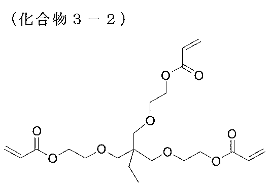

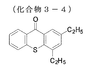

化合物3-1~3-5を調製した上記塗布液を上記で作製した下塗り層が形成された支持体01の下塗り層側の面に、#4.4のワイヤーバーを用いて塗布し、乾燥した。70℃で90秒加熱して、円盤状液晶性化合物を配向させた。その後、ただちに70℃の温度条件で、290mJ/cm2の紫外線を照射して、円盤状液晶性化合物を重合させ、配向状態を固定した。これを光学補償層01とする。光学補償層01をAxoscan(Axometric社製)で測定し、Re(550)=0nm、Rth(550)=220nmであることを確認した。
[光学補償層02の形成]
(配向膜P-1の形成)
上記の下塗り層を形成した支持体01上に下記の配向膜P-1形成用塗布液を#2のワイヤーバーで連続的に塗布した。この配向膜P-1形成用塗布液の塗膜が形成された支持体01を60℃の温風で60秒間乾燥し、配向膜P-1を形成した。
(配向膜P-1の形成)
上記の下塗り層を形成した支持体01上に下記の配向膜P-1形成用塗布液を#2のワイヤーバーで連続的に塗布した。この配向膜P-1形成用塗布液の塗膜が形成された支持体01を60℃の温風で60秒間乾燥し、配向膜P-1を形成した。
<配向膜P-1形成用塗布液>
下記光配向用素材 1.00質量部
水 16.00質量部
ブトキシエタノール 42.00質量部
プロピレングリコールモノメチルエーテル 42.00質量部
下記光配向用素材 1.00質量部
水 16.00質量部
ブトキシエタノール 42.00質量部
プロピレングリコールモノメチルエーテル 42.00質量部
-光配向用素材-

(配向膜P-1の露光)
空気下にて空冷メタルハライドランプ(アイグラフィックス社製)をUV(ultraviolet(紫外線))ランプとして用い、露光マスクとワイヤーグリッド偏光子とを介して、上記で形成した配向膜P-1の真上から偏光紫外線照射を行うことで、配向膜P-1に配向パターンを付与し、パターン配向膜Q-1を形成した。紫外線の照度は、UV-A領域(波長380nm~320nmの積算)において100mW/cm2、照射量はUV-A領域において、50mJ/cm2とした。
空気下にて空冷メタルハライドランプ(アイグラフィックス社製)をUV(ultraviolet(紫外線))ランプとして用い、露光マスクとワイヤーグリッド偏光子とを介して、上記で形成した配向膜P-1の真上から偏光紫外線照射を行うことで、配向膜P-1に配向パターンを付与し、パターン配向膜Q-1を形成した。紫外線の照度は、UV-A領域(波長380nm~320nmの積算)において100mW/cm2、照射量はUV-A領域において、50mJ/cm2とした。
次に、配向膜Q-1上に、下記の組成物A-1を塗布した塗膜をホットプレート上で110℃に加熱した。その後、60℃に冷却した後、窒素雰囲気下で高圧水銀灯を用いて波長365nmの紫外線を100mJ/cm2の照射量で塗膜に照射した。これにより、液晶化合物の配向を固定化した。固定化した液晶化合物の膜厚は2.0μmであった。これを光学補償層02とする。光学補償層02をAxoscan(Axometric社製)で測定し、Re(550)=140nm、Rth(550)=70nmであることを確認した。すなわち、光学補償層02はλ/4板として機能する。
<組成物A-1>
下記液晶化合物L-2 42.00質量部
下記液晶化合物L-3 42.00質量部
下記液晶化合物L-4 16.00質量部
下記重合開始剤PI-1 0.50質量部
下記レベリング剤T-1 0.50質量部
メチルエチルケトン 176.00質量部
シクロペンタノン 44.00質量部
下記液晶化合物L-2 42.00質量部
下記液晶化合物L-3 42.00質量部
下記液晶化合物L-4 16.00質量部
下記重合開始剤PI-1 0.50質量部
下記レベリング剤T-1 0.50質量部
メチルエチルケトン 176.00質量部
シクロペンタノン 44.00質量部
-液晶化合物L-2-

-液晶化合物L-3-

-液晶化合物L-4-

-重合開始剤PI-1-

-レベリング剤T-1-

[実施例1]
[傾斜液晶層1の形成]
上記の光学補償層02と同様にして下塗り層を形成した支持体01上に配向膜P-1を形成した。次に、配向膜P-1の表面の法線から20度傾いた方向から偏光紫外線を照射しパターン配向膜Q-2を形成した。次に、パターン配向膜Q-2の上に下記傾斜液晶用組成物を#2のワイヤーバーで連続的に塗布し、120℃で1分間熟成した。続いて、30℃、窒素雰囲気下で500mJ/cm2の照射量で紫外線照射することにより塗布した傾斜液晶用組成物を硬化し、傾斜液晶層1を得た。
傾斜液晶層1の液晶の配向は偏光紫外線の透過軸方向に対して平均16°傾斜していることを確認した。
[傾斜液晶層1の形成]
上記の光学補償層02と同様にして下塗り層を形成した支持体01上に配向膜P-1を形成した。次に、配向膜P-1の表面の法線から20度傾いた方向から偏光紫外線を照射しパターン配向膜Q-2を形成した。次に、パターン配向膜Q-2の上に下記傾斜液晶用組成物を#2のワイヤーバーで連続的に塗布し、120℃で1分間熟成した。続いて、30℃、窒素雰囲気下で500mJ/cm2の照射量で紫外線照射することにより塗布した傾斜液晶用組成物を硬化し、傾斜液晶層1を得た。
傾斜液晶層1の液晶の配向は偏光紫外線の透過軸方向に対して平均16°傾斜していることを確認した。
(傾斜液晶層用組成物)
・円盤状液晶化合物D-1 100質量部
・界面活性剤S-1 0.1質量部
・開始剤Irg-907(BASF製) 3.0質量部
・溶剤(MEK(メチルエチルケトン)/シクロヘキサノン=90/10(質量比))
溶質濃度が30質量%となる量
・円盤状液晶化合物D-1 100質量部
・界面活性剤S-1 0.1質量部
・開始剤Irg-907(BASF製) 3.0質量部
・溶剤(MEK(メチルエチルケトン)/シクロヘキサノン=90/10(質量比))
溶質濃度が30質量%となる量
-円盤状液晶化合物D-1-
円盤状液晶化合物として、特開2007-131765号公報に記載の下記円盤状液晶化合物D-1を使用した。
円盤状液晶化合物として、特開2007-131765号公報に記載の下記円盤状液晶化合物D-1を使用した。
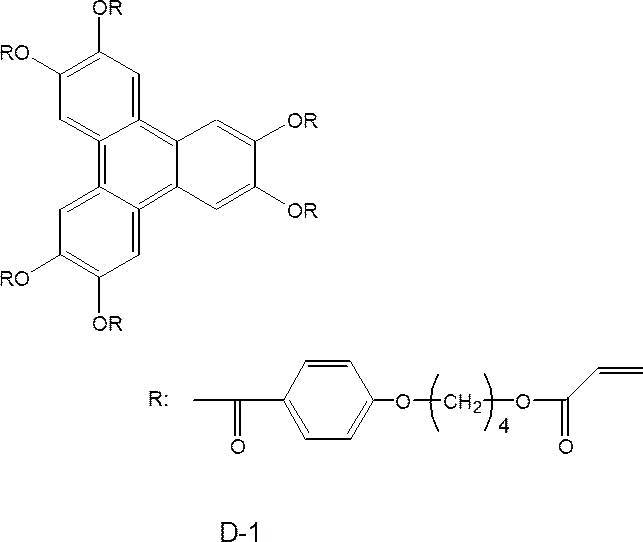
-界面活性剤S-1-
界面活性剤S-1は、特許第5774518号に記載された化合物であり、下記構造を有する。
界面活性剤S-1は、特許第5774518号に記載された化合物であり、下記構造を有する。
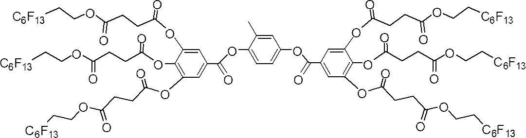
S-1
[コレステリック液晶層G1の作製]
つづいて、形成した傾斜液晶層1上に、下記コレステリック液晶層G1の組成物を#8のワイヤーバーで連続的に塗布した後、90℃で1分間熟成した。続いて、熟成後の組成物層に対して、30℃にて光源(UVP社製、2UV・トランスイルミネーター)を用いて波長365nmの光を2mW/cm2の照射強度で60秒間紫外線を照射した。続いて、30℃、窒素雰囲気下で500mJ/cm2の照射量で紫外線を照射して液晶化合物の重合反応を実施することにより、コレステリック配向状態が固定化されたコレステリック液晶層G1を得た。断面SEM画像を解析した結果、コレステリック液晶相由来の明部及び暗部(明暗線)の傾斜角度は15度、ピッチは370nmであった。また、反射する円偏光は、左円偏光であった。
つづいて、形成した傾斜液晶層1上に、下記コレステリック液晶層G1の組成物を#8のワイヤーバーで連続的に塗布した後、90℃で1分間熟成した。続いて、熟成後の組成物層に対して、30℃にて光源(UVP社製、2UV・トランスイルミネーター)を用いて波長365nmの光を2mW/cm2の照射強度で60秒間紫外線を照射した。続いて、30℃、窒素雰囲気下で500mJ/cm2の照射量で紫外線を照射して液晶化合物の重合反応を実施することにより、コレステリック配向状態が固定化されたコレステリック液晶層G1を得た。断面SEM画像を解析した結果、コレステリック液晶相由来の明部及び暗部(明暗線)の傾斜角度は15度、ピッチは370nmであった。また、反射する円偏光は、左円偏光であった。
(コレステリック液晶層G1の組成物)
下記組成の試料溶液を調製した。
・下記構造で表される液晶性化合物LC-1 100質量部
・界面活性剤S-1 0.1質量部
・キラル剤化合物CD-1 5.5質量部
・キラル剤化合物CD-2 5.5質量部
・フッ素系界面活性剤B1 0.03質量部
・開始剤Irg-907(BASF製) 2.0質量部
・溶剤(MEK(メチルエチルケトン)/シクロヘキサノン=90/10(質量比))
溶質濃度が30質量%となる量
下記組成の試料溶液を調製した。
・下記構造で表される液晶性化合物LC-1 100質量部
・界面活性剤S-1 0.1質量部
・キラル剤化合物CD-1 5.5質量部
・キラル剤化合物CD-2 5.5質量部
・フッ素系界面活性剤B1 0.03質量部
・開始剤Irg-907(BASF製) 2.0質量部
・溶剤(MEK(メチルエチルケトン)/シクロヘキサノン=90/10(質量比))
溶質濃度が30質量%となる量
-液晶性化合物LC-1-
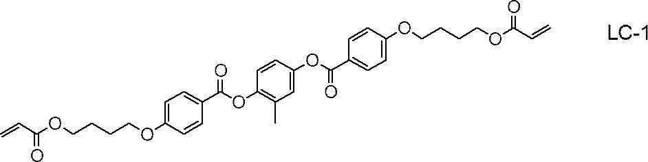
-キラル剤化合物CD-1-
以下の合成手順に従い、一般的な手法にてキラル剤化合物CD-1を合成した。
なお、キラル剤化合物CD-1は、螺旋方向は左であり、温度変化又は光照射により螺旋誘起力が変化しないキラル剤である。
以下の合成手順に従い、一般的な手法にてキラル剤化合物CD-1を合成した。
なお、キラル剤化合物CD-1は、螺旋方向は左であり、温度変化又は光照射により螺旋誘起力が変化しないキラル剤である。

-キラル剤化合物CD-2の合成-
特開2002-338575号公報に準じて、下記キラル剤化合物CD-2を合成して使用した。
なお、キラル剤化合物CD-2は、螺旋方向は右であり、光照射により螺旋誘起力が変化するキラル剤である(キラル剤Xに該当する)。
特開2002-338575号公報に準じて、下記キラル剤化合物CD-2を合成して使用した。
なお、キラル剤化合物CD-2は、螺旋方向は右であり、光照射により螺旋誘起力が変化するキラル剤である(キラル剤Xに該当する)。
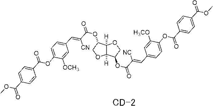
-フッ素系界面活性剤B1-
数値は質量%である。
数値は質量%である。

上記の工程により、支持体01と、パターン配向膜Q-2と、傾斜液晶層1と、傾斜液晶層1の上に配置されたコレステリック液晶層G1とを有する光学積層体01を作製した。
次に、キラル剤化合物CD-1とキラル剤化合物CD-2の添加量を調整した以外は実施例1と同様にして、傾斜液晶層1上にコレステリック液晶層B1を有する光学積層体02と、傾斜液晶層1上にコレステリック液晶層R1とを有する光学積層体03とを作製した。
ここで、コレステリック液晶層B1の傾斜角度は15度、ピッチは300nmであった。コレステリック液晶層R1の傾斜角度は15度、ピッチは420nmであった。
光学積層体02、01、03の積層順に粘着剤(SK粘着剤、総研化学製)を介して貼合し、反射フィルム01を作製した。
ここで、コレステリック液晶層B1の傾斜角度は15度、ピッチは300nmであった。コレステリック液晶層R1の傾斜角度は15度、ピッチは420nmであった。
光学積層体02、01、03の積層順に粘着剤(SK粘着剤、総研化学製)を介して貼合し、反射フィルム01を作製した。
[偏光板の作製]
(偏光子の作製)
特開2001-141926号公報の実施例1を参考に、2対のニップロール間に周速差を与え、長手方向に延伸し、厚み15μmの偏光子01を調製した。
(偏光子の作製)
特開2001-141926号公報の実施例1を参考に、2対のニップロール間に周速差を与え、長手方向に延伸し、厚み15μmの偏光子01を調製した。
(貼り合わせ)
上記作製した偏光子01と、アルカリ鹸化処理した支持体01とを、PVA((株)クラレ製、PVA-117H)3%水溶液を接着剤として、偏光子01の両面に貼りあわせて偏光板01(直線偏光板)を作製した。
上記作製した偏光子01と、アルカリ鹸化処理した支持体01とを、PVA((株)クラレ製、PVA-117H)3%水溶液を接着剤として、偏光子01の両面に貼りあわせて偏光板01(直線偏光板)を作製した。
[評価]
GW2280(BenQ社製)を分解し、液晶セルの両面に配置されている偏光板を両面とも剥がした。次に、視認側の液晶セルの面に粘着剤(SKダイン、総研化学製)を介して偏光板01を貼合した。またバックライト側の面に、液晶セル上に光学補償層01、光学補償層02、反射フィルム01、黒PETの順に、粘着剤(SKダイン、総研化学製)を用いて貼合した。この時、光学補償層02と、反射フィルム01の光学積層体02とが、接するように配置した。また、光学補償層02は、λ/4板であり、直線偏光通過後、右円偏光になるように遅相軸の向きを配置した。
GW2280(BenQ社製)を分解し、液晶セルの両面に配置されている偏光板を両面とも剥がした。次に、視認側の液晶セルの面に粘着剤(SKダイン、総研化学製)を介して偏光板01を貼合した。またバックライト側の面に、液晶セル上に光学補償層01、光学補償層02、反射フィルム01、黒PETの順に、粘着剤(SKダイン、総研化学製)を用いて貼合した。この時、光学補償層02と、反射フィルム01の光学積層体02とが、接するように配置した。また、光学補償層02は、λ/4板であり、直線偏光通過後、右円偏光になるように遅相軸の向きを配置した。
GW2280のバックライトユニットを外した状態で、反射フィルム01のコレステリック液晶層における明暗線の傾斜方向に光源を配置した。光源として人工太陽照明灯XC-100(セリック株式会社製)を使用した。パネルの法線対して50度の角度から入射するように光源を配置し、パネル正面から画像を視認した。その結果、画像視認性が非常に高いことを確認した。
[実施例2]
[パターン配向膜の形成]
実施例1で作製した配向膜P-1に、露光マスクを介して、以下に示す4回の紫外線照射を行い、パターン配向膜Q-3を形成した。
[パターン配向膜の形成]
実施例1で作製した配向膜P-1に、露光マスクを介して、以下に示す4回の紫外線照射を行い、パターン配向膜Q-3を形成した。
1回目の露光は、空気下にて空冷メタルハライドランプ(アイグラフィックス社製)をUV(ultraviolet(紫外線))ランプを、ワイヤーグリッド偏光子と露光マスクを介して、配向膜P-1表面の法線から20度傾いた方向から偏光紫外線を照射した。露光マスクは、図22に示すような、1辺100μmの正方形状の開口(透過部)が、100μmの等間隔で上下左右に配置された10cm四方のものを用いた。
2回目の露光は、1回目の露光時から露光マスクを右方向に100μmずらし、次に、配向膜P-1が積層された支持体01および露光マスクを法線に対して時計回りに90°回転してから、1回目の露光と同様に偏光紫外線光を照射した。
3回目の露光は、2回目の露光時から露光マスクを下方向に100μmずらし、次に、配向膜P-1が積層された支持体01および露光マスクを法線に対して時計回りに90°回転してから、1回目の露光と同様に偏光紫外線光を照射した。
4回目の露光は、3回目の露光時から露光マスクを左方向に100μmずらし、次に、配向膜P-1が積層された支持体01および露光マスクを法線に対して時計回りに90°回転してから、1回目の露光と同様に偏光紫外線光を照射した。
3回目の露光は、2回目の露光時から露光マスクを下方向に100μmずらし、次に、配向膜P-1が積層された支持体01および露光マスクを法線に対して時計回りに90°回転してから、1回目の露光と同様に偏光紫外線光を照射した。
4回目の露光は、3回目の露光時から露光マスクを左方向に100μmずらし、次に、配向膜P-1が積層された支持体01および露光マスクを法線に対して時計回りに90°回転してから、1回目の露光と同様に偏光紫外線光を照射した。
ここで、紫外線の照度は、どの露光時も、UV-A領域(波長380nm~320nmの積算)において100mW/cm2、照射量はUV-A領域において、50mJ/cm2とした。
[コレステリック液晶層の作製]
配向膜Q-3上に、実施例1と同様に、傾斜液晶用組成物を塗布して傾斜液晶層2を形成した。次に、傾斜液晶層2の上に、実施例1と同様にして、コレステリック液晶層G1の組成物を塗布、硬化して、コレステリック液晶層G2を作製した。
配向膜Q-3上に、実施例1と同様に、傾斜液晶用組成物を塗布して傾斜液晶層2を形成した。次に、傾斜液晶層2の上に、実施例1と同様にして、コレステリック液晶層G1の組成物を塗布、硬化して、コレステリック液晶層G2を作製した。
上記の工程により、支持体01と、パターン配向膜Q-3と、傾斜液晶層2と、傾斜液晶層2の上に配置されたコレステリック液晶層G2とを有する光学積層体04を作製した。
上記と同様に、配向膜Q-3上に、傾斜液晶用組成物を塗布して傾斜液晶層2を形成した。次に、傾斜液晶層2の上に、実施例1と同様にして、コレステリック液晶層B1の組成物を塗布、硬化して、コレステリック液晶層B2を作製した。
上記と同様に、配向膜Q-3上に、傾斜液晶用組成物を塗布して傾斜液晶層2を形成した。次に、傾斜液晶層2の上に、実施例1と同様にして、コレステリック液晶層R1の組成物を塗布、硬化して、コレステリック液晶層R2を作製した。
上記と同様に、配向膜Q-3上に、傾斜液晶用組成物を塗布して傾斜液晶層2を形成した。次に、傾斜液晶層2の上に、実施例1と同様にして、コレステリック液晶層R1の組成物を塗布、硬化して、コレステリック液晶層R2を作製した。
上記の工程により、支持体01と、パターン配向膜Q-3と、傾斜液晶層2と、傾斜液晶層2の上に配置されたコレステリック液晶層B2とを有する光学積層体05、および、支持体01と、パターン配向膜Q-3と、傾斜液晶層2と、傾斜液晶層2の上に配置されたコレステリック液晶層R2とを有する光学積層体06を作製した。
光学積層体05、04、06の積層順に粘着剤(SK粘着剤、総研化学製)を介して貼合し、反射フィルム02を作製した。
光学積層体05、04、06の積層順に粘着剤(SK粘着剤、総研化学製)を介して貼合し、反射フィルム02を作製した。
[評価]
反射フィルム01を反射フィルム02に変更した以外は、実施例1と同様にして、GW2280に反射フィルム02を組み込んだ。この時、光学補償層02と、反射フィルム02の光学積層体04とが、接するように配置した。
反射フィルム01を反射フィルム02に変更した以外は、実施例1と同様にして、GW2280に反射フィルム02を組み込んだ。この時、光学補償層02と、反射フィルム02の光学積層体04とが、接するように配置した。
光源を4辺いずれかの方向の、法線対して50度の角度から入射するように配置して、パネル正面からの画像を視認した。光源を4辺いずれの側に配置した場合でも、パネル正面からの画像視認性が非常に高いことを確認した。
[比較例1]
上記で作製した下塗り層が形成された支持体01の下塗り層側をラビング処理したのち、下記に示すコレステリック液晶組成物1の溶液を、#8のワイヤーバーで連続的に塗布した。その後、コレステリック液晶組成物1の塗膜を90℃で1分間熟成した。続いて、コレステリック液晶組成物1の塗膜に、30℃、窒素雰囲気下で500mJ/cm2の照射量で紫外線を照射して液晶化合物の重合反応を実施することにより、コレステリック配向状態が固定化されたコレステリック液晶層G3を得た。断面SEM画像を解析した結果、傾斜角度は0度、ピッチは355nmであった。また、反射する円偏光は、右円偏光であった。
<コレステリック液晶組成物1>
下記液晶化合物L-1 100.0 質量部
IRGACURE 819 (BASF社製) 10.0 質量部
下記構造のキラル剤A 5.28 質量部
下記構造の界面活性剤 0.08 質量部
溶媒(メチルエチルケトン) 溶質濃度が30質量%となる量
下記液晶化合物L-1 100.0 質量部
IRGACURE 819 (BASF社製) 10.0 質量部
下記構造のキラル剤A 5.28 質量部
下記構造の界面活性剤 0.08 質量部
溶媒(メチルエチルケトン) 溶質濃度が30質量%となる量
-液晶化合物L-1-

-キラル剤A-

-界面活性剤-

次に、キラル剤Aの添加量を調整した以外はそれぞれ上記と同様に、コレステリック液晶組成物の溶液を、ラビング処理された下塗り層が形成された支持体01上に塗布し、コレステリック配向状態が固定化されたコレステリック液晶層B3およびコレステリック液晶層R3を得た。断面SEM画像を解析した結果、コレステリック液晶層B3は傾斜角度は0度、ピッチは290であった。コレステリック液晶層R3は傾斜角度は0度、ピッチは405nmであった。また、反射する円偏光はいずれも、右円偏光であった。
以上により、支持体01と、支持体01の上に配置されたコレステリック液晶層G3とを有する光学積層体07、支持体01と、支持体01の上に配置されたコレステリック液晶層B3とを有する光学積層体08、および、支持体01と、支持体01の上に配置されたコレステリック液晶層R3とを有する光学積層体09を作製した。
光学積層体08、07、09の積層順で粘着剤を介して積層し、反射フィルム03を作製した。
光学積層体08、07、09の積層順で粘着剤を介して積層し、反射フィルム03を作製した。
[評価]
反射フィルム01を反射フィルム03に変更した以外は、実施例1と同様に、GW2280に反射フィルム03を組み込んだ。この時、光学補償層02と、反射フィルム03のコレステリック液晶層B3とが、接するように配置した。
反射フィルム01を反射フィルム03に変更した以外は、実施例1と同様に、GW2280に反射フィルム03を組み込んだ。この時、光学補償層02と、反射フィルム03のコレステリック液晶層B3とが、接するように配置した。
光源を4辺いずれかの方向の、法線対して50度の角度から入射するように配置して、パネル正面からの画像を視認した。光源を4辺いずれの側に配置した場合でも、パネル正面からの画像視認性が非常に悪いことを確認した。
実施例および比較例をまとめた表を、以下に示す。

10,20,30,40,60 コレステリック液晶層
11,12,13,21,22,23,31,32,41,42,43 主面
14,24,34,44 液晶化合物
L1,L2,L3,L4,L5 分子軸
D1,D2,D3,D4 配列軸
θ2,θ5,θ10,θ20,θa1,θa2,θa3,θb1,θb2,θb3 角度
C1,C2,C3 コレステリック液晶相由来の螺旋軸
T1,T2,T3 反射面
15,25,35 明部
16,26,36 暗部
18 円盤状液晶化合物
P1,P2 明部と暗部とが交互に配列された配列方向
52 支持体
54 偏向膜
61 露光装置
62 レーザ
64 光源
65 λ/2板
68 偏光ビームスプリッター
70A,70B ミラー
72A,72B λ/4板
80 反射型液晶表示装置
82 液晶セル
84 直線偏光子
86 λ/4板
88 光吸収層
90 光学補償層
100 組成物層
102 液晶層
102a 傾斜配向面
A,A1,A2,A3,A4,B 領域
T11 工程2-1(工程2Y-1)において液晶化合物の配向処理が実施される温度
T12 工程2-2(工程2Y-2)の冷却処理が実施される温度
R1 厚み方向
I1,I2 外光
I1r,I2r 反射光
M レーザ光
MA 光線
MB 光線
PO 直線偏光
PR 右円偏光
PL 左円偏光
α 交差角
MK マスキング部材
OP 開口
LD レーザ光源
MU 偏光紫外線光
LP 直線偏光子
11,12,13,21,22,23,31,32,41,42,43 主面
14,24,34,44 液晶化合物
L1,L2,L3,L4,L5 分子軸
D1,D2,D3,D4 配列軸
θ2,θ5,θ10,θ20,θa1,θa2,θa3,θb1,θb2,θb3 角度
C1,C2,C3 コレステリック液晶相由来の螺旋軸
T1,T2,T3 反射面
15,25,35 明部
16,26,36 暗部
18 円盤状液晶化合物
P1,P2 明部と暗部とが交互に配列された配列方向
52 支持体
54 偏向膜
61 露光装置
62 レーザ
64 光源
65 λ/2板
68 偏光ビームスプリッター
70A,70B ミラー
72A,72B λ/4板
80 反射型液晶表示装置
82 液晶セル
84 直線偏光子
86 λ/4板
88 光吸収層
90 光学補償層
100 組成物層
102 液晶層
102a 傾斜配向面
A,A1,A2,A3,A4,B 領域
T11 工程2-1(工程2Y-1)において液晶化合物の配向処理が実施される温度
T12 工程2-2(工程2Y-2)の冷却処理が実施される温度
R1 厚み方向
I1,I2 外光
I1r,I2r 反射光
M レーザ光
MA 光線
MB 光線
PO 直線偏光
PR 右円偏光
PL 左円偏光
α 交差角
MK マスキング部材
OP 開口
LD レーザ光源
MU 偏光紫外線光
LP 直線偏光子
Claims (7)
- 直線偏光子と、液晶セルと、λ/4板と、液晶化合物を用いて形成されたコレステリック液晶層とをこの順に有し、
前記コレステリック液晶層の一対の主面のうち少なくとも一方の主面において、前記液晶化合物の分子軸の向きが面内の少なくとも一方向に沿って連続的に回転しながら変化している液晶配向パターンを有し、
前記コレステリック液晶層の主面に垂直な断面において走査型電子顕微鏡にて観察されるコレステリック液晶相由来の明部及び暗部の配列方向が、前記コレステリック液晶層の主面に対して傾斜している、反射型液晶表示装置。 - 前記コレステリック液晶層は、前記明部及び暗部の傾斜方向が異なる2以上の領域を有し、
2以上の前記領域において、異なる方向に光を反射する、請求項1に記載の反射型液晶表示装置。 - 前記コレステリック液晶層は、前記コレステリック液晶相に由来する明部および暗部の形状が波状であり、光拡散性を示す請求項1または2に記載の反射型液晶表示装置。
- 前記コレステリック液晶層は、前記液晶化合物の分子軸が、前記コレステリック液晶層の主面に対して傾斜している請求項1~3のいずれか一項に記載の反射型液晶表示装置。
- 前記明部及び暗部のピッチが異なる2層以上の前記コレステリック液晶層を有する請求項1~4のいずれか一項に記載の反射型液晶表示装置。
- 前記コレステリック液晶層の、前記液晶セルとは反対側に光吸収層を有する請求項1~5のいずれか一項に記載の反射型液晶表示装置。
- バックライトを有さない請求項1~6のいずれか一項に記載の反射型液晶表示装置。
Priority Applications (1)
| Application Number | Priority Date | Filing Date | Title |
|---|---|---|---|
| JP2021509445A JP7192096B2 (ja) | 2019-03-28 | 2020-03-24 | 反射型液晶表示装置 |
Applications Claiming Priority (2)
| Application Number | Priority Date | Filing Date | Title |
|---|---|---|---|
| JP2019-063081 | 2019-03-28 | ||
| JP2019063081 | 2019-03-28 |
Publications (1)
| Publication Number | Publication Date |
|---|---|
| WO2020196507A1 true WO2020196507A1 (ja) | 2020-10-01 |
Family
ID=72611980
Family Applications (1)
| Application Number | Title | Priority Date | Filing Date |
|---|---|---|---|
| PCT/JP2020/012986 Ceased WO2020196507A1 (ja) | 2019-03-28 | 2020-03-24 | 反射型液晶表示装置 |
Country Status (2)
| Country | Link |
|---|---|
| JP (1) | JP7192096B2 (ja) |
| WO (1) | WO2020196507A1 (ja) |
Cited By (1)
| Publication number | Priority date | Publication date | Assignee | Title |
|---|---|---|---|---|
| WO2023032644A1 (ja) * | 2021-08-30 | 2023-03-09 | 富士フイルム株式会社 | 加飾フィルム、成型体、及び、物品 |
Citations (4)
| Publication number | Priority date | Publication date | Assignee | Title |
|---|---|---|---|---|
| JPH10115828A (ja) * | 1996-08-23 | 1998-05-06 | Seiko Epson Corp | 表示素子及びそれを用いた電子機器 |
| JPH11231304A (ja) * | 1998-02-10 | 1999-08-27 | Citizen Watch Co Ltd | 液晶表示装置 |
| WO2017030176A1 (ja) * | 2015-08-20 | 2017-02-23 | 富士フイルム株式会社 | 投映システムおよび投映システムの中間像スクリーンの製造方法 |
| WO2017169696A1 (ja) * | 2016-03-28 | 2017-10-05 | 富士フイルム株式会社 | 反射層の製造方法および反射層 |
Family Cites Families (2)
| Publication number | Priority date | Publication date | Assignee | Title |
|---|---|---|---|---|
| JP2006293393A (ja) * | 2006-07-05 | 2006-10-26 | Seiko Epson Corp | 反射板、反射板の製造方法、液晶装置、電子機器 |
| JP6149006B2 (ja) * | 2014-06-18 | 2017-06-14 | 富士フイルム株式会社 | 反射フィルムおよび反射フィルムを有するディスプレイ |
-
2020
- 2020-03-24 JP JP2021509445A patent/JP7192096B2/ja active Active
- 2020-03-24 WO PCT/JP2020/012986 patent/WO2020196507A1/ja not_active Ceased
Patent Citations (4)
| Publication number | Priority date | Publication date | Assignee | Title |
|---|---|---|---|---|
| JPH10115828A (ja) * | 1996-08-23 | 1998-05-06 | Seiko Epson Corp | 表示素子及びそれを用いた電子機器 |
| JPH11231304A (ja) * | 1998-02-10 | 1999-08-27 | Citizen Watch Co Ltd | 液晶表示装置 |
| WO2017030176A1 (ja) * | 2015-08-20 | 2017-02-23 | 富士フイルム株式会社 | 投映システムおよび投映システムの中間像スクリーンの製造方法 |
| WO2017169696A1 (ja) * | 2016-03-28 | 2017-10-05 | 富士フイルム株式会社 | 反射層の製造方法および反射層 |
Cited By (1)
| Publication number | Priority date | Publication date | Assignee | Title |
|---|---|---|---|---|
| WO2023032644A1 (ja) * | 2021-08-30 | 2023-03-09 | 富士フイルム株式会社 | 加飾フィルム、成型体、及び、物品 |
Also Published As
| Publication number | Publication date |
|---|---|
| JP7192096B2 (ja) | 2022-12-19 |
| JPWO2020196507A1 (ja) | 2021-12-09 |
Similar Documents
| Publication | Publication Date | Title |
|---|---|---|
| JP7076530B2 (ja) | コレステリック液晶層、積層体、光学異方体、反射膜、コレステリック液晶層の製造方法、偽造防止媒体、および、判定方法 | |
| JP7472182B2 (ja) | コレステリック液晶層の製造方法、コレステリック液晶層、液晶組成物、硬化物、光学異方体、反射層 | |
| US11275271B2 (en) | Display comprising a transparent screen having a cholesteric liquid crystal layer exhibiting selective reflectivity attached to a light guide plate | |
| TWI377223B (en) | Biaxial film iii | |
| CN108885293B (zh) | 反射层的制造方法及反射层 | |
| JP7174765B2 (ja) | ウェアラブルディスプレイデバイス | |
| JP6757460B2 (ja) | 構造体および構造体の製造方法 | |
| WO2019013284A1 (ja) | 液晶組成物、反射層の製造方法、反射層、硬化物、光学異方体 | |
| JPWO2020075711A1 (ja) | 光学積層体、導光素子およびar表示デバイス | |
| JPWO2019013292A1 (ja) | 反射層の製造方法及び反射層 | |
| JP6815491B2 (ja) | 透明スクリーンおよび映像投影システム | |
| US11693278B2 (en) | Liquid crystal diffraction element and method for producing liquid crystal diffraction element | |
| JP7173914B2 (ja) | 画像表示装置 | |
| JP7247324B2 (ja) | 合わせガラスおよびヘッドアップディスプレイ | |
| JP7192096B2 (ja) | 反射型液晶表示装置 | |
| JPWO2018159757A1 (ja) | 反射層の製造方法 | |
| WO2020196550A1 (ja) | 光学部材、照明装置、および、スクリーン | |
| WO2025070398A1 (ja) | ヘッドアップディスプレイシステム用反射部材、ヘッドアップディスプレイシステム |
Legal Events
| Date | Code | Title | Description |
|---|---|---|---|
| 121 | Ep: the epo has been informed by wipo that ep was designated in this application |
Ref document number: 20776646 Country of ref document: EP Kind code of ref document: A1 |
|
| ENP | Entry into the national phase |
Ref document number: 2021509445 Country of ref document: JP Kind code of ref document: A |
|
| NENP | Non-entry into the national phase |
Ref country code: DE |
|
| 122 | Ep: pct application non-entry in european phase |
Ref document number: 20776646 Country of ref document: EP Kind code of ref document: A1 |