WO2020196382A1 - ロータコア及びその製造方法 - Google Patents
ロータコア及びその製造方法 Download PDFInfo
- Publication number
- WO2020196382A1 WO2020196382A1 PCT/JP2020/012657 JP2020012657W WO2020196382A1 WO 2020196382 A1 WO2020196382 A1 WO 2020196382A1 JP 2020012657 W JP2020012657 W JP 2020012657W WO 2020196382 A1 WO2020196382 A1 WO 2020196382A1
- Authority
- WO
- WIPO (PCT)
- Prior art keywords
- rotor core
- magnet
- hole
- manufacturing
- bond magnet
- Prior art date
- Legal status (The legal status is an assumption and is not a legal conclusion. Google has not performed a legal analysis and makes no representation as to the accuracy of the status listed.)
- Ceased
Links
Images










Classifications
-
- H—ELECTRICITY
- H02—GENERATION; CONVERSION OR DISTRIBUTION OF ELECTRIC POWER
- H02K—DYNAMO-ELECTRIC MACHINES
- H02K1/00—Details of the magnetic circuit
- H02K1/06—Details of the magnetic circuit characterised by the shape, form or construction
- H02K1/22—Rotating parts of the magnetic circuit
-
- H—ELECTRICITY
- H02—GENERATION; CONVERSION OR DISTRIBUTION OF ELECTRIC POWER
- H02K—DYNAMO-ELECTRIC MACHINES
- H02K1/00—Details of the magnetic circuit
- H02K1/06—Details of the magnetic circuit characterised by the shape, form or construction
- H02K1/22—Rotating parts of the magnetic circuit
- H02K1/27—Rotor cores with permanent magnets
-
- H—ELECTRICITY
- H02—GENERATION; CONVERSION OR DISTRIBUTION OF ELECTRIC POWER
- H02K—DYNAMO-ELECTRIC MACHINES
- H02K15/00—Processes or apparatus specially adapted for manufacturing, assembling, maintaining or repairing of dynamo-electric machines
- H02K15/02—Processes or apparatus specially adapted for manufacturing, assembling, maintaining or repairing of dynamo-electric machines of stator or rotor bodies
-
- H—ELECTRICITY
- H02—GENERATION; CONVERSION OR DISTRIBUTION OF ELECTRIC POWER
- H02K—DYNAMO-ELECTRIC MACHINES
- H02K15/00—Processes or apparatus specially adapted for manufacturing, assembling, maintaining or repairing of dynamo-electric machines
- H02K15/02—Processes or apparatus specially adapted for manufacturing, assembling, maintaining or repairing of dynamo-electric machines of stator or rotor bodies
- H02K15/03—Processes or apparatus specially adapted for manufacturing, assembling, maintaining or repairing of dynamo-electric machines of stator or rotor bodies having permanent magnets
Definitions
- This disclosure relates to a rotor core and its manufacturing method.
- a flux barrier which is a region with low magnetic permeability, is provided.
- the magnetic flux density on the surface of the rotor can be controlled, for example, the magnetic flux density can be increased to improve the performance of the motor (Patent Document 1).
- a bond magnet is used as the rotor core magnet.
- the orientation direction and the degree of orientation of the bond magnet are determined by the magnetic field generated by the alignment mold at the time of injection molding.
- the rotor core is provided with a flux barrier, the magnetic field due to the alignment mold is affected.
- the magnetic flux density in the bond magnet portion decreases, the degree of orientation of the bond magnet decreases, and the performance of the motor may decrease.
- An object of the present disclosure is to provide a method for manufacturing a rotor core capable of controlling the influence on the degree of orientation of a bonded magnet while obtaining the effect of providing a flux barrier, and a rotor core manufactured by the method.
- the first aspect of the present disclosure covers a method for manufacturing a rotor core (10).
- the manufacturing method includes a step of preparing a rotor core body (11) which is formed in a cylindrical shape and is provided with a plurality of magnet slots (12) and a plurality of through holes (13) which are independent of each other and extend in the height direction, and a rotor core.
- the process of inserting and the material for the bond magnet are injected into the magnet slot (12) of the rotor core body (11) arranged in the mold (20) and into which the jig (21) is inserted to form the bond magnet (15). It is provided with a step of forming.
- the bond magnet (15) when the bond magnet (15) is formed, a jig (21) having a predetermined magnetic permeability is inserted into the through hole (13), so that the through hole (13) remains as a gap.
- the magnetic permeability is different from that in the case of.
- a second aspect of the present disclosure includes, in the first aspect, a step of removing the jig (21) from the through hole (13) after the step of forming the bond magnet (15). ..
- the effect of the through hole (13) as a flux barrier can be obtained, and the orientation direction of the bond magnet can be controlled by providing the through hole (13).
- the bond magnet (15) uses a thermoplastic resin as a binder.
- the jig (21) is inserted into only a part of the plurality of through holes (13).
- the desired orientation direction and degree of orientation in the bond magnet (15) can be obtained by selecting the through hole (13) into which the jig (21) is inserted.
- the jig (21) has a magnetic permeability equal to or higher than the magnetic permeability of the rotor core main body (11).
- the magnetic flux density of the alignment magnet (22) in the through hole (13) portion can be made equal to or higher than the case where the jig (21) is not inserted.
- the through hole (13) is formed at a position where the magnetic flux of the alignment magnet (22) is blocked.
- the through hole (13) is arranged at a position that affects the orientation direction and the degree of orientation of the bond magnet (15), the influence can be controlled.
- the through hole (13) is formed so as to avoid a region lateral to the bond magnet (15) in the orientation direction thereof. It is a thing.
- the effect of the present disclosure can be obtained when the through hole (13) is formed at a position that affects the orientation direction and the degree of orientation of the bond magnet (15).
- the through holes (13) are formed at both ends of each magnetic pole formed by the bond magnet (15).
- the through hole (13) is formed asymmetrically with respect to the center of each magnetic pole formed by the bond magnet (15). It is a thing.
- the position of the magnetic pole center in the rotor core can be changed from the case where there is no through hole (13).
- the tenth aspect of the present disclosure is a rotor core manufactured by any of the above-mentioned first to ninth aspects.
- the influence of the through hole (13) on the orientation direction and the degree of orientation of the bond magnet (15) can be controlled.
- FIG. 1 is a diagram schematically showing a rotor core of the present disclosure.
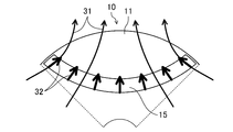
- FIG. 2 is a diagram showing a process of forming a bond magnet when a through hole is not provided.
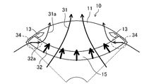
- FIG. 3 is a diagram showing a process of forming a bond magnet when a through hole is provided and a jig is not used.
- FIG. 4 is a diagram showing a process of forming a bond magnet in the case of the present disclosure in which a through hole is provided and a jig is used.
- FIG. 5 is a diagram showing a manufacturing process of the rotor core of the present disclosure.
- FIG. 6 is a diagram showing a process of forming another bond magnet in the case of the present disclosure in which a through hole is provided and a jig is used.
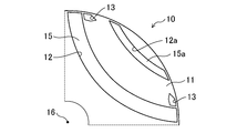
- FIG. 7 is a diagram illustrating the configuration of a bond magnet in particular with respect to the rotor core main body of the present disclosure.
- FIG. 8 is a diagram illustrating another configuration of the bonded magnet in particular with respect to the rotor core main body of the present disclosure.
- FIG. 9 is a diagram illustrating still another configuration of the bond magnet in particular for the rotor core body of the present disclosure.
- FIG. 10 is a diagram illustrating still another configuration of the bond magnet in particular for the rotor core body of the present disclosure.
- FIG. 11 is a diagram illustrating still another configuration of the bond magnet in particular for the rotor core body of the present disclosure.
- FIG. 12 is a diagram illustrating still another configuration of the bond magnet in particular for the rotor core body of the present disclosure.
- FIG. 13 is a diagram illustrating, in particular, the shape of the through hole in the rotor core main body of the present disclosure.
- FIG. 14 is a diagram illustrating another shape of the through hole in particular for the rotor core main body of the present disclosure.
- FIG. 15 is a diagram illustrating still another shape of the through hole in particular for the rotor core body of the present disclosure.
- FIG. 16 is a diagram illustrating, in particular, the shape of the through hole in the rotor core main body of the present disclosure.
- FIG. 17 is a diagram illustrating a region in which the arrangement of through holes should be avoided in the rotor core main body of the present disclosure.
- FIG. 18 is a diagram illustrating still another example of the shape of the through hole and the tooth position with respect to the rotor core main body of the present disclosure.
- Embodiment 1 The first embodiment will be described.
- the method for manufacturing the rotor core of the present embodiment is a method for manufacturing the rotor core (10) as shown in FIG. 1 described below.
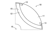
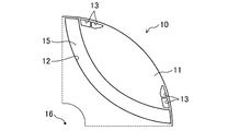
- FIG. 1 schematically shows a rotor core (10) manufactured in this embodiment.
- the rotor core (10) has a configuration in which a bond magnet (15), a through hole (13), and a shaft hole (14) are provided with respect to the rotor core main body (11).
- the rotor core body (11) is formed in a cylindrical shape by laminating, for example, electromagnetic steel plates.
- the bond magnet (15) is formed in a magnet slot (12) which is a hole provided in the rotor core body (11) so as to extend in the height direction.
- the bond magnets (15) have an inwardly convex arc shape, and four bond magnets (15) are formed rotationally symmetrically with respect to the center of rotation (16).
- the through hole (13) is a hole provided independently of the magnet slot (12) so as to penetrate the rotor core main body (11) in the vertical direction.
- the shaft hole (14) is provided in the center of the rotor core main body (11), and a drive shaft (not shown) for driving the load is fixed there.
- the bond magnet (15) has a magnet slot (15) in a state where the rotor core body (11) is arranged in a mold (20) provided with an alignment magnet (22), as shown in FIG. It is formed in 12) by injection molding or the like.
- the degree of orientation of the bond magnet (15) is determined by the magnetic flux of the alignment magnet (22).
- the degree of orientation is represented by magnet Br / (magnetic powder Br ⁇ Vol%) (magnet Br is the residual magnetic flux density of the bonded magnet, magnetic powder Br is the residual magnetic flux density of the magnetic powder, and Vol% is the magnetic powder volume filling rate). ..
- the through hole (13) has a lower magnetic permeability than the rotor core body (11) and functions as a flux barrier. Therefore, the through hole (13) makes it possible to increase the magnetic flux density on the surface of the rotor core (10), control the distribution of the magnetic flux density, etc., and have the effects of improving motor performance, reducing vibration by reducing harmonics, reducing iron loss, etc. Is realized.
- the through hole (13) functions as a flux barrier, the magnetic flux of the alignment magnet (22) when molding the bond magnet (15) is affected, and as a result, the orientation of the bond magnet (15) is affected. receive.
- the orientation direction changes, the degree of orientation decreases, and the like. This will be described below.
- FIG. 2 is a diagram schematically showing the magnetic flux of the alignment magnet (22) and the orientation direction of the bond magnet (15) when the bond magnet (15) is formed in the case where the through hole (13) is not provided. is there.
- FIG. 2 shows only the fan-shaped range including one magnet slot (12) of the rotor cores (10).
- the arrow (31) indicates the magnetic flux of the alignment magnet (22) provided in the mold (20). This magnetic flux determines the orientation (degree of orientation, orientation direction) of the bond magnet (15) indicated by the arrow (32).
- FIG. 3 schematically shows the magnetic flux of the alignment magnet (22) and the orientation direction of the bond magnet (15) when the bond magnet (15) is formed with respect to the rotor core body (11) having the through hole (13). It is a figure shown in. FIG. 3 also shows the same range as that of FIG. 2 of the rotor core (10). Since the through hole (13) functions as a flux barrier, the magnetic flux of the alignment magnet (22) takes the form of, for example, an arrow (32a), avoiding the region of the through hole (13). As a result, especially in the region (34) where the magnetic flux is blocked by the through hole (13), the direction of the magnetic flux changes and the magnetic flux density becomes low as compared with the case of FIG. 2 without the through hole (13). As a result, in the region (34) of the bond magnet (15), the direction of orientation changes and the degree of orientation becomes low. This causes the performance of the motor to fluctuate and deteriorate.
- FIG. 4 shows the present embodiment.
- FIG. 4 also illustrates the same range as in FIG.
- the bond magnet (15) is formed in a state where a jig (21) having a magnetic permeability equivalent to that of the rotor core main body (11) is inserted into the through hole (13).
- the rotor core body (11) For example, electromagnetic steel sheets punched into the same shape by press working may be laminated.
- the electrical steel sheets are processed into a disk shape having openings corresponding to the magnet slots (12), through holes (13), and shaft holes (14), and are laminated in the same shape.
- the prepared rotor core body (11) is arranged in the mold (20).
- the mold (20) has a fixed mold having a recess (20a) into which the rotor core main body (11) can be arranged, and a movable mold (not shown) in which the recess (20a) is closed to form a cavity.
- the orientation magnets (22), which are permanent magnets, and the pole pieces (23) are alternately arranged in the circumferential direction around the recess (20a).
- the number of the alignment magnet (22) and the pole piece (23) is provided according to the number of magnetic poles so as to correspond to the magnet slot (12) of the rotor core main body (11). Therefore, in this embodiment, four are provided.
- Each pole piece (23) is configured to apply a magnetic field to a rotor core body (11) provided in the cavity by magnetic flux from a contacting alignment magnet (22).
- the jig (21) In the rotor core body (11) arranged in the mold (20), insert the jig (21) into the through hole (13).
- the jig (21) has the same magnetic permeability as the rotor core body (11).
- the jig (21) may be inserted into the through hole (13) first, and then the rotor core body (11) may be arranged in the mold (20). After that, the mold (20) is molded to form a material for a bond magnet for forming a bond magnet (15) in the magnet slot (12).
- the material for the bonded magnet used in this embodiment is a mixture of a non-magnetic powdery or granular magnet material and a binder.
- a binder a thermoplastic resin such as nylon resin or PPS (Polyphenylene sulfide) resin may be used.
- the material for the bond magnet supplied to the magnet slot (12) solidifies to become the bond magnet (15).
- the magnet is oriented by the magnetic flux of the alignment magnet (22) and has a predetermined orientation direction and degree of orientation.
- the mold (20) is opened, the rotor core body (11) on which the bond magnet (15) is formed is taken out, and the jig (21) is pulled out from the through hole (13).
- the rotor core (10) that suppresses or prevents the influence of the through hole (13) when forming the bond magnet (15) while realizing the performance improvement by having the through hole (13) as the flux barrier. Can be manufactured.
- the rotor core body (11) is the same as the rotor core (10) shown in FIG.
- the method for manufacturing the rotor core (10) is basically the same as the method described with reference to FIG.
- FIG. 6 shows a step of forming a bond magnet (15) in a magnet slot (12) of a rotor core main body (11) arranged in a mold (20) in the present embodiment, corresponding to FIGS. 2 and 3.
- the jig (21a) has a higher magnetic permeability than the rotor core body (11)
- the magnetic flux of the alignment magnet (22) is concentrated on the jig (21a) portion (through hole (13) portion).
- the magnetic flux density increases in this portion.
- the degree of orientation can be increased in the region (34) where the degree of orientation is lowered. Further, the orientation direction of the bond magnet (15) can be directed toward the through hole (13). Thereby, the magnetic flux density distribution on the outer peripheral surface of the rotor core (10) can be further controlled.
- FIG. 7 is a diagram showing a fan-shaped range including one bonded magnet (15) (magnet slot (12)) for the rotor core (10) shown in FIG.
- Both ends of the bond magnet (15) are located near the outer circumference of the rotor core main body (11), and have an arcuate shape that is convex inward, and are formed so as to extend substantially over the range shown in FIG.
- One magnetic pole is formed by such a bond magnet (15). Further, using this as one pattern, the bond magnet (15) is formed so as to repeat four times rotationally symmetrically with respect to the center of rotation (16) (see FIG. 1). As will be described later, one magnetic pole may be formed by a plurality of bonded magnets (15) (magnet slots (12)).
- the through hole (13) is located on the outer peripheral side of the rotor core body (11) with respect to the bond magnet (15) when viewed from the center of rotation (16). Further, through holes (13) are formed at both ends of the magnetic poles with respect to the bond magnets (15) constituting one magnetic pole.
- the through hole (13) is arranged at a position where the magnetic flux of the alignment magnet (22) is blocked when the bond magnet (15) is formed. If there is a through hole (13) at such a position, the influence on the degree of orientation and the orientation direction of the bond magnet (15) becomes large. Therefore, the effect of inserting the jig (21) to form the bond magnet (15) becomes remarkable. On the contrary, it is avoided to provide a through hole (13) in a region lateral to the magnetic flux of the alignment magnet (22) and the orientation direction of the bond magnet (15). It can be said that these are both ends of the bond magnet (15) and are located inside the pattern of the bond magnet (15) (center side of the magnetic pole) in the circumferential direction of the rotor core body (11).
- FIGS. 8 to 12 are shown in FIGS. 8 to 12.
- the magnet slots are formed in a plurality of layers (for example, two layers). That is, in addition to the magnet slot (12) similar to that in FIG. 7, another magnet slot (12a) is provided on the outer peripheral side of the rotor core main body (11). Further, a bond magnet (15a) is provided in the magnet slot (12a). The magnet slot (12) and the magnet slot (12a) are formed so that the pattern of such two layers repeats in a rotationally symmetric manner. Through holes (13) are formed near both ends of the inner magnet slot (12). Further, the through hole (13) is located inside the rotor core body (11) from the magnet slot (12a), but is located outside the magnet slot (12) inside.
- FIG. 9 has an arc shape as a whole as in FIG. 7, but a magnet slot (12c) divided into two is provided. A bond magnet (15c) is formed for each magnet slot (12). The through holes (13) are arranged near both ends of the two magnet slots (12c) forming the magnetic poles.
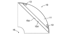
- a linear magnet slot (12d) and a bond magnet (15d) are formed instead of the arc shape.
- Through holes (13) are also formed at both ends of one magnetic pole.
- a magnet slot (12e) and a bond magnet (15e) are provided in an outwardly convex arc shape.
- a range corresponding to one sixth of the rotor core (10) is shown.
- the through hole (13) is located near the end of the magnet slot (12e) and is located inside the magnet slot (12e) in the circumferential direction of the rotor core main body (11).
- the through hole (13) is provided on the center side of the rotor core (10) with respect to the magnet slot (12e). Also in this case, the effect of suppressing the leakage of magnetic flux is exhibited.
- two linear magnet slots (12f) are arranged in a V shape open on the outer peripheral side to form one magnetic pole.
- the through hole (13) is near the end of a plurality of bonded magnets (15) corresponding to one magnetic pole, is on the outer peripheral side of the magnet slot (12f) when viewed from the center of rotation (16), and It is arranged in the inner part of the bond magnet (15f) in the circumferential direction.
- each through hole (13) has a polygonal (pentagonal) cross section.
- FIG. 13 has a quadrangular shape
- FIG. 14 has a circular shape
- FIG. 15 has an elliptical cross-sectional shape.
- the through hole (13) can take various shapes. Since the shape affects the magnetic flux of the bond magnet (15) as a flux barrier, it can be designed according to the performance of the target motor and the like.
- the number of through holes (13) provided at one location is not limited to one. As shown in FIG. 16, two or more through holes (13) may be provided at the end of the magnet slot (12).
- the respective shapes are not limited, and different shapes may be combined. This also makes it possible to design the function as a flux barrier.
- the through hole (13) is formed so as to avoid the region where the shape of the magnet slot (12) is extended to the outer peripheral side of the rotor core. This is shown in FIG.
- FIG. 17 an arc-shaped magnet slot (12) similar to that in FIG. 7 is formed.
- the end portion of the magnet slot (12 g) has a value farther from the outer circumference of the rotor core (10) than in the case of FIG. 7. Therefore, there is a region (17) in which the shape of the magnet slot (12 g) is extended toward the outer circumference of the rotor core (10).
- the orientation direction of the bond magnet (15 g) is indicated by an arrow (32) as in FIG. 2 and the like.
- the region (17) is a region corresponding to the side of the bond magnet (15 g) when viewed in the direction of the arrow (32) (orientation direction).
- a through hole (13) is provided in this area (17). Further, it is assumed that a jig (21) having a higher magnetic permeability than the rotor core body (11) is inserted and the rotor core body (11) is arranged in the mold (20). At this time, the magnetic flux of the alignment magnet (22) is concentrated on the jig (21) having a high magnetic permeability inserted in the through hole (13), and the density is low in the portion of the bond magnet (15 g). That is, the alignment magnetic flux leaks toward the through hole (13), and the desired orientation direction and degree of orientation of the bond magnet (15 g) cannot be obtained.
- the through hole (13) is not arranged outside the bond magnet (15) (s) (s) corresponding to one magnetic pole in the circumferential direction of the rotor core body (11).
- the region (17) corresponding to the side of the bond magnet (15) with respect to the orientation direction. can be considered. Also in this case, the through hole (13) is preferably arranged so as to avoid the region (17).
- FIG. 18 shows yet another example of the through hole (13).
- through holes (13) are provided at both ends of the bond magnets (15) (s) (s) corresponding to each magnetic pole in the circumferential direction of the rotor core body (11).
- it is formed in a portion near the center of the bond magnet (15). Further, it is formed asymmetrically in the circumferential direction with respect to the center of the magnetic pole when viewed from the center of rotation (16).
- three through holes (13) are provided in a rectangular shape extending diagonally with respect to the radial direction of the rotor core main body (11).
- the through hole (13) also functions as a flux barrier in this case. Therefore, as compared with the case where this is not provided, the position of the magnetic pole center by the bond magnet (15) shifts in the circumferential direction of the rotor core main body (11). As a result, the effect of improving the controllability of the motor using the rotor core (10) is realized.
- a rotor core body (11) formed in a cylindrical shape and provided with a plurality of magnet slots (12) and a plurality of through holes (13) independently of each other and extending in the height direction is provided.
- the step of preparing, the step of arranging the rotor core body (11) in the mold (20) provided with the alignment magnet (22), and the step of arranging a part or all of the through holes (13) have a predetermined magnetic permeability.
- the process of inserting the jig (21) and the material for the bond magnet are injected into the magnet slot (12) of the rotor core body (11) arranged in the mold (20) and into which the jig (21) is inserted. It includes a step of forming a bond magnet (15).
- a step of removing the jig (21) from the through hole (13) is provided after the step of forming the bond magnet (15).
- the magnetic flux indicated by the arrow (32) of the alignment magnet (22) does not have a through hole (13). It becomes the same as the case of. Therefore, the degree of orientation and the direction of orientation of the bond magnet (15) are the same as when the through hole (13) is not provided. As a result, the effect of providing the through hole (13) can be realized, and the influence of the through hole (13) on the degree of orientation and the direction of orientation of the bond magnet (15) can be avoided.
- One of the effects of providing the through hole (13) as a flux barrier is to improve the magnetic flux density on the rotor surface by concentrating the magnetic flux of the bond magnet and improve the motor performance. Further, the magnetic flux density distribution on the rotor surface can be controlled to reduce harmonics by making it into a rectangular wave shape, for example, and it is possible to reduce vibration and iron loss.
- the bond magnet (15) uses a thermoplastic resin as a binder. As a result, the material for the bond magnet can be injected and supplied to the magnet slot of the rotor core body (11) to form the bond magnet (15).
- the jig (21) may be inserted into only a part of the plurality of through holes (13).
- FIG. 5 shows a case where the jig (21) is inserted into all the through holes (13).
- the influence of the alignment magnet (22) on the magnetic flux can be suppressed for all the through holes (13).
- the degree of orientation and the orientation direction of the bond magnet (15) are found in the through holes (13) in which the jig (21) is not inserted. Affects. This may be done depending on the performance of the target motor and the like.
- the jig (21) may have a magnetic permeability equal to or higher than the magnetic permeability of the rotor core main body (11). If they are the same, the degree of orientation and orientation direction of the bond magnet (15) can be realized as in the case where the through hole (13) is not formed. Further, when it has a higher magnetic permeability, the orientation direction of the bond magnet (15) can be oriented in the direction of the through hole (13), and the degree of orientation can be increased in the vicinity of the through hole (13).
- the through hole (13) may be formed at a position that blocks the magnetic flux of the alignment magnet (22).
- the flux barrier has a large effect of blocking the magnetic flux of the alignment magnet (22) and changing the degree of orientation and the orientation direction of the bond magnet (15). Therefore, the effect of suppressing the influence becomes remarkable.
- the through hole (13) is preferably formed so as to avoid a region on the side of the bond magnet (15) in the orientation direction.
- the through holes (13) are preferably formed at both ends of each magnetic pole formed by the bond magnet (15). As a result, it is possible to suppress a short circuit of the magnetic flux of one bond magnet (15), a short circuit of the magnetic flux between the other bond magnet (15), and the like, and it is possible to improve the performance of the motor.
- the through hole (13) may be formed asymmetrically with respect to the center of each magnetic pole formed by the bond magnet (15). In this way, the position of the magnetic pole center generated by the bond magnet (15) can be shifted in the circumferential direction of the rotor core main body (11) as compared with the case where there is no through hole (13). This contributes to improving the controllability of the motor.
- the present disclosure is useful for the rotor core and its manufacturing method.
Landscapes
- Engineering & Computer Science (AREA)
- Power Engineering (AREA)
- Manufacturing & Machinery (AREA)
- Permanent Field Magnets Of Synchronous Machinery (AREA)
- Iron Core Of Rotating Electric Machines (AREA)
- Manufacture Of Motors, Generators (AREA)
Abstract
ロータコア(10)の製造方法において、以下の工程を備える。円筒状に形成され、互いに独立し且つ高さ方向に延びる複数の磁石スロット(12)及び複数の貫通孔(13)が設けられたロータコア本体(11)を準備する工程。ロータコア本体(11)を、配向磁石(22)が設けられた金型(20)に配置する工程。一部又は全ての貫通孔(13)に、所定の透磁率を有する治具(21)を挿入する工程。金型(20)に配置され且つ治具(21)が挿入されたロータコア本体(11)の前記磁石スロット(12)に、ボンド磁石用材料を注入してボンド磁石(15)を形成する工程。
Description
本開示は、ロータコア及びその製造方法に関するものである。
モータに用いるロータコアにおいて、透磁率が低い領域であるフラックスバリアを設けることが行われる。これにより、ロータ表面にける磁束密度を制御し、例えば磁束密度を高めてモータの性能を向上することができる(特許文献1)。
ロータコアの磁石として、ボンド磁石が用いられる。この場合、ボンド磁石の配向方向及び配向度は、射出成形される時の配向金型による磁場で決定される。この際、ロータコアにフラックスバリアが設けられていると、配向金型による磁場が影響を受ける。これによりボンド磁石部分における磁束密度が低下し、ボンド磁石の配向度が低下して、モータの性能が低下することがある。
本開示の目的は、フラックスバリアを設ける効果を得ながら、ボンド磁石の配向度に対する影響を制御できるロータコアの製造方法及びこれにより製造されたロータコアを提供することである。
本開示の第1の態様は、ロータコア(10)の製造方法を対象とする。製造方法は、円筒状に形成され、互いに独立し且つ高さ方向に延びる複数の磁石スロット(12)及び複数の貫通孔(13)が設けられたロータコア本体(11)を準備する工程と、ロータコア本体(11)を、配向磁石(22)が設けられた金型(20)に配置する工程と、一部又は全ての貫通孔(13)に、所定の透磁率を有する治具(21)を挿入する工程と、金型(20)に配置され且つ治具(21)が挿入されたロータコア本体(11)の前記磁石スロット(12)に、ボンド磁石用材料を注入してボンド磁石(15)を形成する工程とを備える。
第1の態様では、ボンド磁石(15)を成形する際には貫通孔(13)に所定の透磁率を有する治具(21)が挿入されているので、貫通孔(13)を空隙のままにしている場合とは異なる透磁率となっている。これにより、ボンド磁石(15)における配向磁石(22)による磁場を制御し、ボンド磁石の配向方向及び配向度を制御することができる。
本開示の第2の態様は、上記第1の態様において、ボンド磁石(15)を形成する工程の後に、前記治具(21)を前記貫通孔(13)から除去する工程を備えるものである。
第2の態様では、フラックスバリアとしての貫通孔(13)の効果を得ると共に、貫通孔(13)を設けたことによるボンド磁石の配向方向を制御することができる。
本開示の第3の態様は、上記第1又は第2の態様において、ボンド磁石(15)は、熱可塑性樹脂をバインダーとするものである。
本開示の第4の態様は、上記第1~第3の態様において、治具(21)は、複数の前記貫通孔(13)のうちの一部のみに挿入するものである。
第4の態様では、治具(21)を挿入する貫通孔(13)を選択することにより、ボンド磁石(15)における望ましい配向方向及び配向度を得ることができる。
本開示の第5の態様は、上記第1~第4の態様において、治具(21)は、ロータコア本体(11)の透磁率と同じ又はそれよりも高い透磁率を有するものである。
第5の態様では、貫通孔(13)部分における配向磁石(22)の磁束密度について、治具(21)が挿入されていない場合と同等又はそれよりも高い密度とすることができる。
本開示の第6の態様は、上記第1~第5の態様において、貫通孔(13)は、前記配向磁石(22)の磁束を遮る位置に形成されているものである。
第6の態様では、ボンド磁石(15)の配向方向及び配向度に影響する位置に貫通孔(13)が配置されている場合について、その影響を制御することができる。
本開示の第7の態様は、上記第第1~第6の態様において、貫通孔(13)は、ボンド磁石(15)に対し、その配向方向に関して側方の領域を避けて形成されているものである。
第7の態様では、ボンド磁石(15)の配向方向及び配向度に影響する位置に貫通孔(13)が形成されている場合において、本開示の効果を得ることができる。
本開示の第8の態様は、上記第1~第7の態様において、貫通孔(13)は、ボンド磁石(15)により形成される各磁極の両端部に形成されているものである。
第8の態様では、隣接する磁極間におけるボンド磁石(15)の磁束の短絡を抑制することができる。
本開示の第9の態様は、上記第第1~第8の態様において、貫通孔(13)は、ボンド磁石(15)により形成される各磁極の中心に対して、非対称に形成されているものである。
第9の態様では、貫通孔(13)が無い場合とは、ロータコアにおける磁極中心の位置を変えることができる。
本開示の第10の態様は、上記第1~第9の態様のいずれかの方法により製造されたロータコアである。
第10の態様では、フラックスバリアとしての貫通孔(13)を設けたロータコアにおいて、貫通孔(13)がボンド磁石(15)の配向方向及び配向度に及ぼす影響を制御することができる。
《実施形態1》
実施形態1について説明する。本実施形態のロータコアの製造方法は、以下に説明する図1のようなロータコア(10)を製造する方法である。
実施形態1について説明する。本実施形態のロータコアの製造方法は、以下に説明する図1のようなロータコア(10)を製造する方法である。
―ロータコアの構造―
図1に、本実施形態において製造するロータコア(10)を模式的に示す。ロータコア(10)は、ロータコア本体(11)に対し、ボンド磁石(15)、貫通孔(13)及び軸孔(14)が設けられた構成を有する。ロータコア本体(11)は、例えば電磁鋼板が積層されて円筒状に構成されている。ボンド磁石(15)は、ロータコア本体(11)に高さ方向に延びるように設けられた孔である磁石スロット(12)内に形成されている。図1の例では、ボンド磁石(15)は内側に凸の弧状であり、回転中心(16)に対して回転対称に4つ形成されている。貫通孔(13)は、ロータコア本体(11)を縦方向に貫通するように、磁石スロット(12)とは独立して設けられた孔である。軸孔(14)はロータコア本体(11)の中心に設けられ、ここに、負荷を駆動するための駆動軸(図示しない)が固定される。
図1に、本実施形態において製造するロータコア(10)を模式的に示す。ロータコア(10)は、ロータコア本体(11)に対し、ボンド磁石(15)、貫通孔(13)及び軸孔(14)が設けられた構成を有する。ロータコア本体(11)は、例えば電磁鋼板が積層されて円筒状に構成されている。ボンド磁石(15)は、ロータコア本体(11)に高さ方向に延びるように設けられた孔である磁石スロット(12)内に形成されている。図1の例では、ボンド磁石(15)は内側に凸の弧状であり、回転中心(16)に対して回転対称に4つ形成されている。貫通孔(13)は、ロータコア本体(11)を縦方向に貫通するように、磁石スロット(12)とは独立して設けられた孔である。軸孔(14)はロータコア本体(11)の中心に設けられ、ここに、負荷を駆動するための駆動軸(図示しない)が固定される。
ボンド磁石(15)は、後に更に説明するが、図5に示すように、配向磁石(22)が備えられた金型(20)にロータコア本体(11)が配置された状態において、磁石スロット(12)に射出成形等により形成される。この際、配向磁石(22)の磁束により、ボンド磁石(15)の配向度が決定される。尚、配向度は、磁石Br/(磁粉Br×Vol%)で表される(磁石Brはボンド磁石の残留磁束密度、磁粉Brは磁粉の残留磁束密度、Vol%は磁粉体積充填率である)。
―貫通孔の影響について―
貫通孔(13)の部分は、ロータコア本体(11)に比べて透磁率が低く、フラックスバリアとして機能する。従って、貫通孔(13)により、ロータコア(10)の表面における磁束密度の上昇、磁束密度の分布の制御等が可能となり、モータの性能向上、高調波低減による振動低減、鉄損低減等の効果が実現する。
貫通孔(13)の部分は、ロータコア本体(11)に比べて透磁率が低く、フラックスバリアとして機能する。従って、貫通孔(13)により、ロータコア(10)の表面における磁束密度の上昇、磁束密度の分布の制御等が可能となり、モータの性能向上、高調波低減による振動低減、鉄損低減等の効果が実現する。
その一方、貫通孔(13)がフラックスバリアとして機能するので、ボンド磁石(15)を成形する際の配向磁石(22)の磁束が影響を受け、結果としてボンド磁石(15)の配向が影響を受ける。例えば、配向方向の変化、配向度の低下等が生じる。これに関して以下に説明する。
まず、図2は、貫通孔(13)を設けない場合について、ボンド磁石(15)を成形する際の配向磁石(22)の磁束とボンド磁石(15)の配向方向を模式的に示す図である。図2では、ロータコア(10)のうち、1つの磁石スロット(12)を含む扇型の範囲だけを示している。矢印(31)は、金型(20)に設けられた配向磁石(22)の磁束を示す。この磁束により、矢印(32)として示すボンド磁石(15)の配向(配向度、配向方向)が決まる。
次に、図3は、貫通孔(13)を有するロータコア本体(11)について、ボンド磁石(15)を成形する際の配向磁石(22)の磁束とボンド磁石(15)の配向方向を模式的に示す図である。図3でも、ロータコア(10)の図2と同様の範囲を示す。貫通孔(13)がフラックスバリアとして機能するので、配向磁石(22)の磁束は、貫通孔(13)の領域を避けて例えば矢印(32a)のような形態を取る。これにより、特に貫通孔(13)によって磁束が阻害された領域(34)において、貫通孔(13)の無い図2の場合とは磁束の向きが変化し、且つ、磁束密度が低くなる。この結果、ボンド磁石(15)の領域(34)の部分において、配向の方向が変化し、且つ、配向度が低くなる。これは、モータの性能を変動、低下させる原因となる。
つまり、フラックスバリアとして貫通孔(13)を設けることの効果が得られる一方、貫通孔(13)を有するロータコア本体(11)に単純にボンド磁石(15)を成型した場合、このような影響も発生する。これに対応するためには、例えば配向金型が出力する磁束密度を上げることが考えられる。しかし、そのためには金型をサイズアップすること等が必要となり、コストも上昇してしまう。
そこで、図4には、本実施形態を示す。図4でも、図2と同様の範囲を図示している。本実施形態では、貫通孔(13)に対し、ロータコア本体(11)と同等の透磁率を有する治具(21)を挿入した状態においてボンド磁石(15)を形成する。
このようにすると、ボンド磁石(15)の成型の際、配向磁石(22)の磁束は、貫通孔(13)が設けられていない図2の場合と同様になる。これにより、フラックスバリアとして貫通孔(13)を設ける効果を実現すると共に、ロータコア(10)を製造する際に貫通孔(13)がボンド磁石(15)の配向度及び配向の方向に及ぼす影響を避けることができる。
―ロータコアの製造方法―
本実施形態のロータコアの製造方法について更に説明する。まず、図4で説明したように、ロータコア本体(11)と透磁率が同等である治具(21)を用いる場合を説明する。
本実施形態のロータコアの製造方法について更に説明する。まず、図4で説明したように、ロータコア本体(11)と透磁率が同等である治具(21)を用いる場合を説明する。
最初の工程として、ロータコア本体(11)を準備する。例えば、プレス加工により同一形状に打ち抜き加工した電磁鋼板を積層して構成してもよい。この場合、それぞれ電磁鋼板は磁石スロット(12)、貫通孔(13)及び軸孔(14)に対応する開口を有する円板状に加工され、形状を揃えて積層される。
次に、図5に示す工程を説明する。準備されたロータコア本体(11)は、金型(20)に配置される。金型(20)は、ロータコア本体(11)を配置することのできる凹部(20a)を有する固定型と、凹部(20a)を閉じてキャビティを形成する可動型(図示は省略)とを有する。
また、金型(20)において、凹部(20a)の周囲に、永久磁石である配向磁石(22)と、ポールピース(23)とが周方向に交互に配置されている。配向磁石(22)及びポールピース(23)は、ロータコア本体(11)の磁石スロット(12)と対応するように磁極数に応じた数が設けられている。従って、本実施形態ではいずれも4つ設けられている。各ポールピース(23)は、接触する配向磁石(22)からの磁束によって、キャビティに設けられたロータコア本体(11)に磁場を印加されるように構成されている。
金型(20)に配置されたロータコア本体(11)において、その貫通孔(13)に治具(21)を挿入する。治具(21)は、ロータコア本体(11)と同等の透磁率を有する。尚、先に貫通孔(13)に治具(21)を挿入し、その後にロータコア本体(11)を金型(20)に配置しても良い。この後、金型(20)を型締めして、磁石スロット(12)にボンド磁石(15)を形成するためのボンド磁石用材料を成形する。
本実施形態において用いるボンド磁石用材料は、磁性を帯びていない粉状乃至粒状の磁石材料とバインダーと混合したものである。バインダーとしては、ナイロン樹脂、PPS(Polyphenylenesulfide)樹脂等の熱可塑性樹脂を用いても良い。磁石スロット(12)に供給されたボンド磁石用材料は、固化してボンド磁石(15)となる。この際、図4に示すように、配向磁石(22)の磁束により配向され、所定の配向方向及び配向度を有するようになる。
この後、金型(20)を開いてボンド磁石(15)が形成されたロータコア本体(11)を取り出し、また、治具(21)を貫通孔(13)から抜き取る。
このようにして、フラックスバリアとしての貫通孔(13)を有することによる性能向上を実現しながら、ボンド磁石(15)形成時における貫通孔(13)の影響を抑制又は防止したロータコア(10)を製造することができる。
(治具の透磁率について)
以上では、ロータコア本体(11)と同等の透磁率を有する治具(21)を用いた。しかし、ロータコア本体(11)よりも透磁率が高い治具(21a)を用いても良い。これについて以下に説明する。
以上では、ロータコア本体(11)と同等の透磁率を有する治具(21)を用いた。しかし、ロータコア本体(11)よりも透磁率が高い治具(21a)を用いても良い。これについて以下に説明する。
この場合も、ロータコア本体(11)については、図1に示すロータコア(10)と同様である。また、ロータコア(10)の製造方法についても、基本的には図5により説明した方法と同様である。
先に述べたとおり、治具(21)の透磁率がロータコア本体(11)と同等の場合、貫通孔(13)が無い場合と同様の配向度、配向方向を有するボンド磁石(15)が実現する(図4)。
これに対し、ロータコア本体(11)よりも高い透磁率を有する治具(21a)を用いる場合を考える。図6は、図2及び図3に対応し、本実施形態において金型(20)に配置されたロータコア本体(11)の磁石スロット(12)にボンド磁石(15)を成形する工程を示す。ここで、治具(21a)はロータコア本体(11)よりも透磁率が高いので、配向磁石(22)の磁束は治具(21a)の部分(貫通孔(13)の部分)に集中し、当該部分において磁束密度が高くなる。
この場合、治具を用いない図3の場合では配向度が低下した領域(34)において、逆に、配向度を高めることができる。また、ボンド磁石(15)における配向方向を貫通孔(13)の方向に向けることができる。これにより、ロータコア(10)の外周面における磁束密度分布を更に制御することができる。
―ボンド磁石及び貫通孔の形状と配置―
次に、ボンド磁石(15)及び貫通孔(13)の形状と配置について説明する。図7は、図1に示すロータコア(10)について、1つのボンド磁石(15)(磁石スロット(12))を含む扇形の範囲を示す図である。
次に、ボンド磁石(15)及び貫通孔(13)の形状と配置について説明する。図7は、図1に示すロータコア(10)について、1つのボンド磁石(15)(磁石スロット(12))を含む扇形の範囲を示す図である。
ボンド磁石(15)は、両端がロータコア本体(11)の外周付近に位置し、且つ、内側に凸の円弧状であり、図7に示す範囲の概ね全体に延びるように形成されている。このようなボンド磁石(15)により、1つの磁極が構成される。また、これを1つのパターンとして、ボンド磁石(15)は、回転中心(16)に対して回転対称に4回繰り返すように形成されている(図1を参照)。尚、後述するが、複数のボンド磁石(15)(磁石スロット(12))によって1つの磁極が構成されていても良い。
貫通孔(13)は、回転中心(16)から見てボンド磁石(15)よりもロータコア本体(11)の外周側に位置する。また、貫通孔(13)は、1つの磁極を構成するボンド磁石(15)に対して、磁極の両端部に形成されている。
このような位置に貫通孔(13)を設けることにより、1つのボンド磁石(15)の磁束の短絡、他のボンド磁石(15)との間の磁束の短絡等を抑制することができ、モータの性能を向上することができる。
また、貫通孔(13)は、ボンド磁石(15)を成形する際に、配向磁石(22)の磁束を遮る位置に配置されている。そのような位置に貫通孔(13)があると、ボンド磁石(15)の配向度、配向方向に対する影響が大きくなる。従って、治具(21)を挿入してボンド磁石(15)を成形することの効果が顕著になる。逆に、配向磁石(22)の磁束、ひいてはボンド磁石(15)における配向方向に対して、側方の領域に貫通孔(13)を設けることは避ける。これは、ボンド磁石(15)の両端部であって、ロータコア本体(11)の円周方向についてボンド磁石(15)のパターンの内側(磁極の中心側)の部分に位置しているとも言える。
但し、図7のような形状及び配置には限られない。まず、磁石スロット(12)(ボンド磁石(15))に関する他の例について、図8~図12に示す。
図8では、磁石スロットは、複数層(例として2層)に形成されている。つまり、図7と同様の磁石スロット(12)に加えて、よりロータコア本体(11)の外周側に、他の磁石スロット(12a)を備えている。また、当該磁石スロット(12a)には、ボンド磁石(15a)が設けられている。磁石スロット(12)及び磁石スロット(12a)は、このような2層をのパターンが回転対称状に繰り返すように形成されている。貫通孔(13)は、内側の磁石スロット(12)の両端付近に形成されている。また、貫通孔(13)は、磁石スロット(12a)よりはロータコア本体(11)の内側であるが、内側の磁石スロット(12)よりは外側に位置している。
図9では、図7と同様に全体としては円弧状であるが、2つに分割された磁石スロット(12c)が設けられている。それぞれの磁石スロット(12)に対して、ボンド磁石(15c)が形成されている。貫通孔(13)は、磁極を構成する2つの磁石スロット(12c)の両端部付近に配置されている。
図10では、円弧状に代えて、直線状の磁石スロット(12d)及びボンド磁石(15d)が形成されている。貫通孔(13)は、ここでも1つの磁極の両端部に形成されている。
図11では、外に凸の円弧状に、磁石スロット(12e)及びボンド磁石(15e)が設けられている。図11の場合、ロータコア(10)の六分の一に相当する範囲を示している。図11においても、貫通孔(13)は、磁石スロット(12e)の端部付近であり、ロータコア本体(11)の周方向について磁石スロット(12e)の内側である部分に位置している。但し、貫通孔(13)は、磁石スロット(12e)よりもロータコア(10)の中心側に設けられている。この場合にも、磁束の漏れを抑制する等の効果は発揮される。
図12では、2つの直線状の磁石スロット(12f)が外周側に開いたV字状に配置されて、1つの磁極を構成している。貫通孔(13)は、1つの磁極に対応する複数のボンド磁石(15)の端部付近であって、回転中心(16)から見て磁石スロット(12f)よりも外周側であり、且つ、円周方向についてボンド磁石(15f)の内側の部分に配置されている。
更に、以上の例示にも限られず、磁石スロット及びそこに設けられるボンド磁石の形状について、様々なパターンを取ることができる。
次に、貫通孔(13)の形状について、図13~図16に示す。図1等では、それぞれの貫通孔(13)は多角形(五角形)の断面を有する。これに対し、図13では四角形、図14では円形、図15では楕円形の断面形状を有する。このように、貫通孔(13)は、様々な形状を取ることができる。形状は、フラックスバリアとしてボンド磁石(15)の磁束に影響するので、目的とするモータの性能等に合わせて設計することができる。
また、1箇所に設ける貫通孔(13)は1つには限定されない。図16に示すように、磁石スロット(12)の端部において、2つ又はそれ以上の貫通孔(13)を設けても良い。それぞれの形状についても限定されず、異なる形状の組み合わせとしても良い。これによっても、フラックスバリアとしての機能を設計することができる。
尚、貫通孔(13)は、磁石スロット(12)の形状をロータコアの外周側に延長した領域を避けて形成する。これに関して図17に示す。
図17では、図7に類似した円弧状の磁石スロット(12)が形成されている。但し、磁石スロット(12g)の端部は、図7の場合に比べてロータコア(10)の外周から離れた位値になっている。従って、磁石スロット(12g)の形状をロータコア(10)の外周に向かって延長した領域(17)が存在する。また、図17では、ボンド磁石(15g)の配向方向を、図2等と同様に矢印(32)により示している。領域(17)は、矢印(32)の方向(配向方向)に見たとき、ボンド磁石(15g)の側方にあたる領域である。
仮に、この領域(17)に貫通孔(13)を設けたとする。また、ロータコア本体(11)よりも透磁率の高い治具(21)を挿入し、金型(20)にロータコア本体(11)を配置したとする。このとき、配向磁石(22)の磁束は、貫通孔(13)に挿入した透磁率の高い治具(21)の方に集中し、ボンド磁石(15g)の部分では密度が低くなる。つまり、貫通孔(13)の方に配向磁束が漏れた状態となり、ボンド磁石(15g)の望ましい配向方向及び配向度が得られなくなる。
このようなことから、領域(17)に貫通孔(13)を配置することは避けるのが好ましい。また、ロータコア本体(11)の周方向について、1つの磁極に対応するボンド磁石(15)(単数又は複数)よりも外側に貫通孔(13)が配置されるのを避けると考えることもできる。
尚、1つの磁極を構成するボンド磁石(15)が単純な1つの円弧以外である場合(例えば図8~図12)においても、配向方向に関してボンド磁石(15)の側方にあたる領域(17)を考えることができる。この場合にも、貫通孔(13)は、当該領域(17)を避けて配置するのが好ましい。
―貫通孔の形状及び配置の他の例―
図18に、貫通孔(13)の更に他の例を示す。図7~図12では、ロータコア本体(11)の周方向について、各磁極に対応するボンド磁石(15)(単数又は複数)の両端部に貫通孔(13)が設けられている。これに対し、図18の場合、ボンド磁石(15)の中央寄りの部分に形成されている。また、回転中心(16)から見て、磁極中心に対し、周方向に非対称に形成されている。具体的には、ロータコア本体(11)の径方向に対して斜めに延びる長方形状に、3つの貫通孔(13)が設けられている。
図18に、貫通孔(13)の更に他の例を示す。図7~図12では、ロータコア本体(11)の周方向について、各磁極に対応するボンド磁石(15)(単数又は複数)の両端部に貫通孔(13)が設けられている。これに対し、図18の場合、ボンド磁石(15)の中央寄りの部分に形成されている。また、回転中心(16)から見て、磁極中心に対し、周方向に非対称に形成されている。具体的には、ロータコア本体(11)の径方向に対して斜めに延びる長方形状に、3つの貫通孔(13)が設けられている。
貫通孔(13)は、この場合にもフラックスバリアとして機能する。従って、これを設けない場合と比較して、ボンド磁石(15)による磁極中心の位置は、ロータコア本体(11)の周方向にずれる。これにより、ロータコア(10)を用いたモータの制御性向上等の効果が実現する。
-実施形態1の効果-
本実施形態のロータコアの製造方法は、円筒状に形成され、互いに独立し且つ高さ方向に延びる複数の磁石スロット(12)及び複数の貫通孔(13)が設けられたロータコア本体(11)を準備する工程と、ロータコア本体(11)を、配向磁石(22)が設けられた金型(20)に配置する工程と、一部又は全ての貫通孔(13)に、所定の透磁率を有する治具(21)を挿入する工程と、金型(20)に配置され且つ治具(21)が挿入されたロータコア本体(11)の磁石スロット(12)に、ボンド磁石用材料を注入してボンド磁石(15)を形成する工程とを備える。
本実施形態のロータコアの製造方法は、円筒状に形成され、互いに独立し且つ高さ方向に延びる複数の磁石スロット(12)及び複数の貫通孔(13)が設けられたロータコア本体(11)を準備する工程と、ロータコア本体(11)を、配向磁石(22)が設けられた金型(20)に配置する工程と、一部又は全ての貫通孔(13)に、所定の透磁率を有する治具(21)を挿入する工程と、金型(20)に配置され且つ治具(21)が挿入されたロータコア本体(11)の磁石スロット(12)に、ボンド磁石用材料を注入してボンド磁石(15)を形成する工程とを備える。
尚、ボンド磁石(15)を形成する工程の後に、治具(21)を貫通孔(13)から除去する工程を備える。
このようにすると、治具(21)とロータコア本体(11)とが同等の透磁率を有するので、配向磁石(22)の矢印(32)により示す磁束は貫通孔(13)を設けない図2の場合と同様になる。従って、ボンド磁石(15)における配向度及び配向の方向についても、貫通孔(13)を設けない場合と同様になる。これにより、貫通孔(13)を設ける効果を実現すると共に、貫通孔(13)がボンド磁石(15)の配向度及び配向の方向に及ぼす影響を避けることができる。
貫通孔(13)をフラックスバリアとして設けることの効果の1つは、ボンド磁石の磁束を集中させることによりロータ表面における磁束密度を向上して、モータ性能を向上させることである。また、ロータ表面における磁束密度分布を制御し、例えば矩形波状にして高調波を低減し、振動の低減、鉄損の低減を実現できる。
また、治具(21)を用いることにより抑制、回避できる影響としては、ボンド磁石(15)における配向度低下に起因したモータ性能の低下が挙げられる。
ボンド磁石(15)は、熱可塑性樹脂をバインダーとする。これにより、ロータコア本体(11)の磁石スロットにボンド磁石用材料を射出供給し、ボンド磁石(15)を成形することができる。
治具(21)は、複数の前記貫通孔(13)のうちの一部のみに挿入しても良い。図5には、全ての貫通孔(13)に治具(21)を挿入する場合を示している。これにより、全ての貫通孔(13)に関して配向磁石(22)の磁束に対する影響を抑制できる。これに対し、一部の貫通孔(13)のみに治具(21)を挿入した場合、治具(21)を挿入しない貫通孔(13)についてはボンド磁石(15)の配向度、配向方向に影響する。目的とするモータの性能等によっては、このようにすることも考えられる。
治具(21)は、前記ロータコア本体(11)の透磁率と同じ又はそれよりも高い透磁率を有していても良い。同じであれば、貫通孔(13)が形成されていない場合と同様のボンド磁石(15)の配向度、配向方向を実現できる。また、より高い透磁率を有する場合、貫通孔(13)の方向にボンド磁石(15)の配向方向を向けることができると共に、貫通孔(13)の近傍において配向度を高めることができる。
貫通孔(13)は、配向磁石(22)の磁束を遮る位置に形成されていても良い。このような場合に、フラックスバリアが配向磁石(22)の磁束を遮ってボンド磁石(15)における配向度及び配向方向を変動させる影響が大きい。従って、当該影響を抑制する効果が顕著になる。
貫通孔(13)は、ボンド磁石(15)に対し、その配向方向に関して側方の領域を避けて形成されているのが好ましい。
このようにすると、特にロータコア本体(11)よりも透磁率が高い治具(21a)を用いた場合に、配向磁石(22)の磁束がボンド磁石(15)の領域から漏れるのを避けることができる。
貫通孔(13)は、ボンド磁石(15)により形成される各磁極の両端部に形成されているのが好ましい。これにより、1つのボンド磁石(15)の磁束の短絡、他のボンド磁石(15)との間の磁束の短絡等を抑制することができ、モータの性能を向上することができる。
また、貫通孔(13)は、ボンド磁石(15)により形成される各磁極の中心に対して、非対称に形成されていても良い。このようにすると、ボンド磁石(15)により生じる磁極中心の位置を、貫通孔(13)が無い場合と比較してロータコア本体(11)の周方向にずらすことができる。これは、モータの制御性向上等に貢献する。
以上、実施形態および変形例を説明したが、特許請求の範囲の趣旨および範囲から逸脱することなく、形態や詳細の多様な変更が可能なことが理解されるであろう。また、以上の実施形態および変形例は、本開示の対象の機能を損なわない限り、適宜組み合わせたり、置換したりしてもよい。
以上説明したように、本開示は、ロータコア及びその製造方法について有用である。
10 ロータコア
11 ロータコア本体
12 磁石スロット
12a~12g 磁石スロット
13 貫通孔
14 軸孔
15 ボンド磁石
15a~15g ボンド磁石
16 回転中心
17 領域
20 金型
20a 凹部
21 治具
21a 治具
22 配向磁石
23 ポールピース
31 矢印
32 矢印
32a 矢印
34 領域
11 ロータコア本体
12 磁石スロット
12a~12g 磁石スロット
13 貫通孔
14 軸孔
15 ボンド磁石
15a~15g ボンド磁石
16 回転中心
17 領域
20 金型
20a 凹部
21 治具
21a 治具
22 配向磁石
23 ポールピース
31 矢印
32 矢印
32a 矢印
34 領域
Claims (10)
- ロータコア(10)の製造方法において、
円筒状に形成され、互いに独立し且つ高さ方向に延びる複数の磁石スロット(12)及び複数の貫通孔(13)が設けられたロータコア本体(11)を準備する工程と、
前記ロータコア本体(11)を、配向磁石(22)が設けられた金型(20)に配置する工程と、
一部又は全ての前記貫通孔(13)に、所定の透磁率を有する治具(21)を挿入する工程と、
前記金型(20)に配置され且つ前記治具(21)が挿入された前記ロータコア本体(11)の前記磁石スロット(12)に、ボンド磁石用材料を注入してボンド磁石(15)を形成する工程とを備えることを特徴とするロータコアの製造方法。 - 請求項1のロータコアの製造方法において、
前記ボンド磁石(15)を形成する工程の後に、前記治具(21)を前記貫通孔(13)から除去する工程を備えることを特徴とするロータコアの製造方法。 - 請求項1又は2のロータコアの製造方法において、
前記ボンド磁石(15)は、熱可塑性樹脂をバインダーとすることを特徴とするロータコアの製造方法。 - 請求項1~3のいずれか1つのロータコアの製造方法において、
前記治具(21)は、複数の前記貫通孔(13)のうちの一部のみに挿入することを特徴とするロータコアの製造方法。 - 請求項1~4のいずれか1つのロータコアの製造方法において、
前記治具(21)は、前記ロータコア本体(11)の透磁率と同じ又はそれよりも高い透磁率を有することを特徴とするロータコアの製造方法。 - 請求項1~5のいずれか1つのロータコアの製造方法において、
前記貫通孔(13)は、前記配向磁石(22)の磁束を遮る位置に形成されていることを特徴とするロータコアの製造方法。 - 請求項1~6のいずれか1つのロータコアの製造方法において、
前記貫通孔(13)は、前記ボンド磁石(15)に対し、その配向方向に関して側方の領域を避けて形成されていることを特徴とするロータコアの製造方法。 - 請求項1~7のいずれか1つのロータコアの製造方法において、
前記貫通孔(13)は、前記ボンド磁石(15)により形成される各磁極の両端部に形成されていることを特徴とするロータコアの製造方法。 - 請求項1~7のいずれか1つロータコアの製造方法において、
前記貫通孔(13)は、前記ボンド磁石(15)により形成される各磁極の中心に対して、非対称に形成されていることを特徴とするロータコアの製造方法。 - 請求項1~9のいずれかの方法により製造されたロータコア。
Applications Claiming Priority (2)
| Application Number | Priority Date | Filing Date | Title |
|---|---|---|---|
| JP2019060460A JP2020162329A (ja) | 2019-03-27 | 2019-03-27 | ロータコア及びその製造方法 |
| JP2019-060460 | 2019-03-27 |
Publications (1)
| Publication Number | Publication Date |
|---|---|
| WO2020196382A1 true WO2020196382A1 (ja) | 2020-10-01 |
Family
ID=72610990
Family Applications (1)
| Application Number | Title | Priority Date | Filing Date |
|---|---|---|---|
| PCT/JP2020/012657 Ceased WO2020196382A1 (ja) | 2019-03-27 | 2020-03-23 | ロータコア及びその製造方法 |
Country Status (2)
| Country | Link |
|---|---|
| JP (1) | JP2020162329A (ja) |
| WO (1) | WO2020196382A1 (ja) |
Cited By (1)
| Publication number | Priority date | Publication date | Assignee | Title |
|---|---|---|---|---|
| WO2024075469A1 (ja) * | 2022-10-04 | 2024-04-11 | パナソニックIpマネジメント株式会社 | 回転子及び電動機 |
Families Citing this family (1)
| Publication number | Priority date | Publication date | Assignee | Title |
|---|---|---|---|---|
| JP7754257B1 (ja) * | 2024-09-30 | 2025-10-15 | 株式会社富士通ゼネラル | 電動機及び圧縮機 |
Citations (5)
| Publication number | Priority date | Publication date | Assignee | Title |
|---|---|---|---|---|
| JPS522492B2 (ja) * | 1972-02-15 | 1977-01-21 | ||
| JP2013126281A (ja) * | 2011-12-14 | 2013-06-24 | Daikin Ind Ltd | 界磁子の製造方法及び界磁子用の端板 |
| WO2013103118A1 (ja) * | 2012-01-06 | 2013-07-11 | 愛知製鋼株式会社 | 内包磁石型同期機およびその回転子 |
| JP2013247782A (ja) * | 2012-05-25 | 2013-12-09 | Jtekt Corp | ロータの着磁装置及びロータの着磁方法 |
| JP2017079575A (ja) * | 2015-10-22 | 2017-04-27 | ダイキン工業株式会社 | ロータの製造方法 |
-
2019
- 2019-03-27 JP JP2019060460A patent/JP2020162329A/ja active Pending
-
2020
- 2020-03-23 WO PCT/JP2020/012657 patent/WO2020196382A1/ja not_active Ceased
Patent Citations (5)
| Publication number | Priority date | Publication date | Assignee | Title |
|---|---|---|---|---|
| JPS522492B2 (ja) * | 1972-02-15 | 1977-01-21 | ||
| JP2013126281A (ja) * | 2011-12-14 | 2013-06-24 | Daikin Ind Ltd | 界磁子の製造方法及び界磁子用の端板 |
| WO2013103118A1 (ja) * | 2012-01-06 | 2013-07-11 | 愛知製鋼株式会社 | 内包磁石型同期機およびその回転子 |
| JP2013247782A (ja) * | 2012-05-25 | 2013-12-09 | Jtekt Corp | ロータの着磁装置及びロータの着磁方法 |
| JP2017079575A (ja) * | 2015-10-22 | 2017-04-27 | ダイキン工業株式会社 | ロータの製造方法 |
Cited By (1)
| Publication number | Priority date | Publication date | Assignee | Title |
|---|---|---|---|---|
| WO2024075469A1 (ja) * | 2022-10-04 | 2024-04-11 | パナソニックIpマネジメント株式会社 | 回転子及び電動機 |
Also Published As
| Publication number | Publication date |
|---|---|
| JP2020162329A (ja) | 2020-10-01 |
Similar Documents
| Publication | Publication Date | Title |
|---|---|---|
| JP5305887B2 (ja) | 永久磁石式回転電機 | |
| US7342338B2 (en) | Permanent magnet electric motor with reduced cogging torque | |
| CN104115369B (zh) | 复合转矩型旋转电机 | |
| CN111181272B (zh) | 用于同步驱动电机的转子 | |
| JP6011693B1 (ja) | ロータの製造方法、及びロータ | |
| EP3358717B1 (en) | Rotor | |
| JP2013198254A (ja) | 回転子および回転電機 | |
| WO2020196382A1 (ja) | ロータコア及びその製造方法 | |
| KR102058872B1 (ko) | 스포크형 모터의 회전자 | |
| JP2016144322A (ja) | 回転電機用ロータおよびその製造方法 | |
| JP6424615B2 (ja) | ロータ及びその製造方法、並びにそれを備えた回転電気機械 | |
| WO2013111301A1 (ja) | 同期電動機の回転子およびその製造方法ならびに同期電動機 | |
| JP2010252417A (ja) | アウターロータ型ipmモータとそのロータ | |
| JP5929147B2 (ja) | 回転電機のロータ構造 | |
| JP2015133825A (ja) | 回転電機用ロータ | |
| JP2013121262A (ja) | 回転電機のロータ及びその製造方法 | |
| JP7654795B2 (ja) | ロータおよびモータ | |
| US20250070604A1 (en) | Rotor and motor | |
| JP6627520B2 (ja) | ロータの製造方法、及びロータ | |
| KR20240157762A (ko) | 내포 자석형 모터 및 그 로터 | |
| JP2024053164A (ja) | ボンド磁石の製造装置および製造方法 | |
| CN116134698A (zh) | 用于电机的转子装置 | |
| JP2021136860A (ja) | 回転電機 | |
| JP2017169294A (ja) | ロータの製造方法 | |
| JP6467912B2 (ja) | 回転電気機械 |
Legal Events
| Date | Code | Title | Description |
|---|---|---|---|
| 121 | Ep: the epo has been informed by wipo that ep was designated in this application |
Ref document number: 20777962 Country of ref document: EP Kind code of ref document: A1 |
|
| NENP | Non-entry into the national phase |
Ref country code: DE |
|
| 122 | Ep: pct application non-entry in european phase |
Ref document number: 20777962 Country of ref document: EP Kind code of ref document: A1 |