WO2020196336A1 - アンカー器具 - Google Patents
アンカー器具 Download PDFInfo
- Publication number
- WO2020196336A1 WO2020196336A1 PCT/JP2020/012490 JP2020012490W WO2020196336A1 WO 2020196336 A1 WO2020196336 A1 WO 2020196336A1 JP 2020012490 W JP2020012490 W JP 2020012490W WO 2020196336 A1 WO2020196336 A1 WO 2020196336A1
- Authority
- WO
- WIPO (PCT)
- Prior art keywords
- anchor
- shaft
- arms
- elongated
- anchor portion
- Prior art date
- Legal status (The legal status is an assumption and is not a legal conclusion. Google has not performed a legal analysis and makes no representation as to the accuracy of the status listed.)
- Ceased
Links
Images


Classifications
-
- A—HUMAN NECESSITIES
- A61—MEDICAL OR VETERINARY SCIENCE; HYGIENE
- A61B—DIAGNOSIS; SURGERY; IDENTIFICATION
- A61B17/00—Surgical instruments, devices or methods
- A61B17/12—Surgical instruments, devices or methods for ligaturing or otherwise compressing tubular parts of the body, e.g. blood vessels or umbilical cord
- A61B17/128—Surgical instruments, devices or methods for ligaturing or otherwise compressing tubular parts of the body, e.g. blood vessels or umbilical cord for applying or removing clamps or clips
- A61B17/1285—Surgical instruments, devices or methods for ligaturing or otherwise compressing tubular parts of the body, e.g. blood vessels or umbilical cord for applying or removing clamps or clips for minimally invasive surgery
-
- A—HUMAN NECESSITIES
- A61—MEDICAL OR VETERINARY SCIENCE; HYGIENE
- A61B—DIAGNOSIS; SURGERY; IDENTIFICATION
- A61B17/00—Surgical instruments, devices or methods
- A61B17/064—Surgical staples, i.e. penetrating the tissue
-
- A—HUMAN NECESSITIES
- A61—MEDICAL OR VETERINARY SCIENCE; HYGIENE
- A61B—DIAGNOSIS; SURGERY; IDENTIFICATION
- A61B17/00—Surgical instruments, devices or methods
- A61B17/064—Surgical staples, i.e. penetrating the tissue
- A61B17/0644—Surgical staples, i.e. penetrating the tissue penetrating the tissue, deformable to closed position
-
- A—HUMAN NECESSITIES
- A61—MEDICAL OR VETERINARY SCIENCE; HYGIENE
- A61B—DIAGNOSIS; SURGERY; IDENTIFICATION
- A61B17/00—Surgical instruments, devices or methods
- A61B17/11—Surgical instruments, devices or methods for performing anastomosis; Buttons for anastomosis
- A61B17/1114—Surgical instruments, devices or methods for performing anastomosis; Buttons for anastomosis of the digestive tract, e.g. bowels or oesophagus
-
- A—HUMAN NECESSITIES
- A61—MEDICAL OR VETERINARY SCIENCE; HYGIENE
- A61B—DIAGNOSIS; SURGERY; IDENTIFICATION
- A61B17/00—Surgical instruments, devices or methods
- A61B17/12—Surgical instruments, devices or methods for ligaturing or otherwise compressing tubular parts of the body, e.g. blood vessels or umbilical cord
- A61B17/122—Clamps or clips, e.g. for the umbilical cord
- A61B17/1227—Spring clips
-
- A—HUMAN NECESSITIES
- A61—MEDICAL OR VETERINARY SCIENCE; HYGIENE
- A61B—DIAGNOSIS; SURGERY; IDENTIFICATION
- A61B90/00—Instruments, implements or accessories specially adapted for surgery or diagnosis and not covered by any of the groups A61B1/00 - A61B50/00, e.g. for luxation treatment or for protecting wound edges
- A61B90/36—Image-producing devices or illumination devices not otherwise provided for
- A61B90/37—Surgical systems with images on a monitor during operation
-
- A—HUMAN NECESSITIES
- A61—MEDICAL OR VETERINARY SCIENCE; HYGIENE
- A61B—DIAGNOSIS; SURGERY; IDENTIFICATION
- A61B17/00—Surgical instruments, devices or methods
- A61B2017/00004—(bio)absorbable, (bio)resorbable or resorptive
-
- A—HUMAN NECESSITIES
- A61—MEDICAL OR VETERINARY SCIENCE; HYGIENE
- A61B—DIAGNOSIS; SURGERY; IDENTIFICATION
- A61B17/00—Surgical instruments, devices or methods
- A61B17/00234—Surgical instruments, devices or methods for minimally invasive surgery
- A61B2017/00292—Surgical instruments, devices or methods for minimally invasive surgery mounted on or guided by flexible, e.g. catheter-like, means
- A61B2017/0034—Surgical instruments, devices or methods for minimally invasive surgery mounted on or guided by flexible, e.g. catheter-like, means adapted to be inserted through a working channel of an endoscope
-
- A—HUMAN NECESSITIES
- A61—MEDICAL OR VETERINARY SCIENCE; HYGIENE
- A61B—DIAGNOSIS; SURGERY; IDENTIFICATION
- A61B17/00—Surgical instruments, devices or methods
- A61B2017/00743—Type of operation; Specification of treatment sites
- A61B2017/00818—Treatment of the gastro-intestinal system
-
- A—HUMAN NECESSITIES
- A61—MEDICAL OR VETERINARY SCIENCE; HYGIENE
- A61B—DIAGNOSIS; SURGERY; IDENTIFICATION
- A61B17/00—Surgical instruments, devices or methods
- A61B2017/00831—Material properties
- A61B2017/00867—Material properties shape memory effect
-
- A—HUMAN NECESSITIES
- A61—MEDICAL OR VETERINARY SCIENCE; HYGIENE
- A61B—DIAGNOSIS; SURGERY; IDENTIFICATION
- A61B17/00—Surgical instruments, devices or methods
- A61B17/064—Surgical staples, i.e. penetrating the tissue
- A61B2017/0641—Surgical staples, i.e. penetrating the tissue having at least three legs as part of one single body
-
- A—HUMAN NECESSITIES
- A61—MEDICAL OR VETERINARY SCIENCE; HYGIENE
- A61B—DIAGNOSIS; SURGERY; IDENTIFICATION
- A61B17/00—Surgical instruments, devices or methods
- A61B17/064—Surgical staples, i.e. penetrating the tissue
- A61B2017/0645—Surgical staples, i.e. penetrating the tissue being elastically deformed for insertion
-
- A—HUMAN NECESSITIES
- A61—MEDICAL OR VETERINARY SCIENCE; HYGIENE
- A61B—DIAGNOSIS; SURGERY; IDENTIFICATION
- A61B17/00—Surgical instruments, devices or methods
- A61B17/064—Surgical staples, i.e. penetrating the tissue
- A61B2017/0647—Surgical staples, i.e. penetrating the tissue having one single leg, e.g. tacks
-
- A—HUMAN NECESSITIES
- A61—MEDICAL OR VETERINARY SCIENCE; HYGIENE
- A61B—DIAGNOSIS; SURGERY; IDENTIFICATION
- A61B17/00—Surgical instruments, devices or methods
- A61B17/11—Surgical instruments, devices or methods for performing anastomosis; Buttons for anastomosis
- A61B2017/1139—Side-to-side connections, e.g. shunt or X-connections
-
- A—HUMAN NECESSITIES
- A61—MEDICAL OR VETERINARY SCIENCE; HYGIENE
- A61B—DIAGNOSIS; SURGERY; IDENTIFICATION
- A61B90/00—Instruments, implements or accessories specially adapted for surgery or diagnosis and not covered by any of the groups A61B1/00 - A61B50/00, e.g. for luxation treatment or for protecting wound edges
- A61B90/36—Image-producing devices or illumination devices not otherwise provided for
- A61B90/37—Surgical systems with images on a monitor during operation
- A61B2090/378—Surgical systems with images on a monitor during operation using ultrasound
- A61B2090/3782—Surgical systems with images on a monitor during operation using ultrasound transmitter or receiver in catheter or minimal invasive instrument
- A61B2090/3784—Surgical systems with images on a monitor during operation using ultrasound transmitter or receiver in catheter or minimal invasive instrument both receiver and transmitter being in the instrument or receiver being also transmitter
Definitions
- the present invention relates to an anchor device for connecting a plurality of tissues.
- Cholecystitis is a disease that causes inflammation of the gallbladder, and cholecystitis is divided into acute cholecystitis and chronic cholecystitis, but the number of cases in Japan is about 100,000 a year.
- cholecystitis mainly include laparoscopic cholecystectomy, percutaneous transhepatic gallbladder drainage, and gallbladder-duodenal bypass surgery.
- Laparoscopic cholecystectomy completes the treatment by surgical excision of the gallbladder, but it is highly invasive and may cause intraoperative and postoperative complications, limiting the patients to whom it can be applied.
- Percutaneous transhepatic gallbladder drainage is a procedure in which a drainage tube is placed in the gallbladder via the liver to drain the stagnant bile in the gallbladder over a period of time. And although it can be applied to high-risk patients, there are problems that the procedure is painful and the tube is blocked or pulled out.
- Gallbladder-duodenal bypass is a method of bypassing the duodenum-duodenum with a gastrointestinal endoscope to remove pus and bile stones, which is less invasive than percutaneous transhepatic drainage, has a shorter treatment time, and is applicable. Although it has the advantage of being wide, bile may leak from the perforated part during the operation because the wall that makes a hole for bypass in the gallbladder and duodenum is done in a free state where the gallbladder and duodenum are not fixed to each other. There's a problem.
- EUS-GBD ultrasonography gallbladder drainage
- EUS-GBD is also performed in a free state in which the gallbladder wall and the gastric wall or the duodenum are not fixed to each other, it requires the skill of a doctor, and there is a problem that accidents due to stent deviation and bile leakage are observed.
- Patent Document 1 describes a device for use in closing a septal defect, wherein the device is an inner portion having a longitudinal axis; integrally with the inner portion. A set of first and second fingers formed, the fingers that can extend substantially radially from the axis, with the first set of fingers at the radially outer end of the finger. A pair of first and second fingers, which are not connected to a pair of two, and the first and second pairs are spaced apart from each other on the axis by the distance of the axis, and A device is disclosed that includes a web covering only one of the first and second finger pairs.
- Patent Document 2 describes a tissue locking tool used for joining a plurality of tissue layers, a base end member which is configured to expand from a delivery state to an unfolded state and has a fixing member, and a delivery state.
- the tissue locking is provided with a tip member configured to expand from the to the unfolded state and a connecting member that connects the base end member to the tip end member and exerts a tensile force between the base end member and the tip end member.
- the end portion of the tool is connected to the connecting member, extends toward the base end side of the base end member, adjusts the length of the connecting member when pulled toward the base end side, and the fixing member is attached to the outer surface of the connecting member.
- Tissue locking characterized in that the proximal member is engaged and detachably attached to the connecting member, and in the deployed state, the proximal member and the distal member lock a plurality of tissue layers.
- Patent Document 3 describes an anchor including a base and a plurality of shape memory anchor arms, wherein the base has a substantially tubular shape, defines a lumen having a center line, and includes a mooring portion.
- the plurality of shape memory anchor arms are connected to the base portion so as to be substantially parallel to the central axis of the base portion, and each of the plurality of shape memory anchor arms is configured to abduct during indwelling.
- An anchors are disclosed that include a shaft portion to be formed and a tissue penetration point connected to and supported by the shaft portion, and each of the shaft portions abducts from the central axis of the base portion upon placement. ..
- Patent No. 4767292 Patent No. 4456482 Special table 2015-528732
- any of the devices of References 1-3 when a plurality of fingers or anchor arms for fixing the tissue are provided integrally with the device body, the plurality of fingers or anchor arms cut both ends of the device body. It is formed by. When the tissue is perforated, the tips of a plurality of fingers or anchor arms come into contact with each other, so that there is a problem that the perforated surface of the tissue becomes rough. There is a need for anchor devices having different configurations that can connect multiple tissues.
- the problem to be solved by the present invention is to provide an anchor device capable of joining a plurality of tissues in a minimally invasive manner and quickly.
- an anchor device for connecting a plurality of tissues, and is separated from a shaft having a longitudinal axis, and a first anchor portion and a second anchor are formed on the shaft, respectively.
- the first anchor portion includes a plurality of elongated anchor arms that can be deployed in a direction away from the longitudinal axis of the shaft toward the second anchor portion with the first position of the shaft as a base point.
- An anchor device is provided in which the second anchor portion has a plurality of elongated anchor arms that can be deployed in a direction away from the longitudinal axis of the shaft toward the first anchor portion with the second position of the shaft as a base point.
- an anchor device for connecting a plurality of tissues, and is a first outer member attached to an outer peripheral surface of the inner shaft separated from the inner shaft having a longitudinal axis. And a second outer member, and a first anchor portion and a second anchor portion formed on the first outer member and the second outer member, respectively, and the first anchor portion is directed toward the second anchor portion.
- It has a plurality of elongated anchor arms that can be deployed in a direction away from the longitudinal axis of the outer member, and the second anchor portion is in a direction away from the longitudinal axis of the second outer member toward the first anchor portion.
- An anchor device is provided that has a plurality of deployable elongated anchor arms.
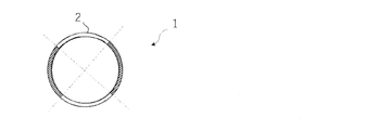
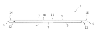
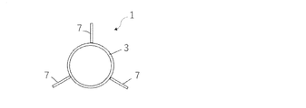
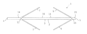
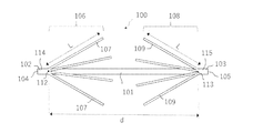
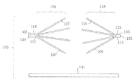
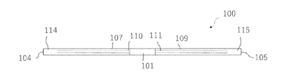
- a side view of the anchor device according to the first embodiment of the present invention is shown, and (B) a plan view of the anchor device is shown. A cross-sectional view of the anchor device along line 2-2 of FIG. 1 (A) is shown. A side view of the anchor device of FIG. 1 in a contracted state is shown.
- a schematic diagram illustrating the adhesion of two tissues using an anchor device is shown.
- (A)-(E) shows a schematic diagram illustrating a procedure for joining two tissues using the anchor device of FIG.
- a schematic end view showing another example of the anchor arm is shown.
- a schematic end view showing another example of the anchor arm is shown.
- a side view showing another example of the anchor device is shown.
- a side view showing another example of the anchor device is shown.
- a side view showing another example of the anchor device is shown.
- a side view showing another example of the anchor device is shown.
- the side view of the anchor device of the 2nd Embodiment of this invention is shown.
- An exploded view of the anchor device of FIG. 12 is shown.
- a side view of the anchor device of FIG. 12 in a contracted state is shown.
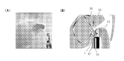
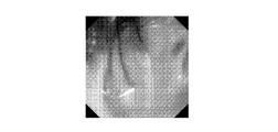
- Extended treatment with a dilator (A) fluoroscopic image, (B) schematic diagram. Endoscopic image after indwelling of the anchor device. Fluoroscopic image after placement of the drainage tube. Three anchor devices are observed at the positions of the arrows.
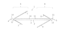
- the anchor device 1 for connecting a plurality of tissues is separated from a long shaft 2 having a longitudinal axis, and each of them is formed on the shaft 2. It includes an anchor portion 6 and a second anchor portion 8.
- the first anchor portion 6 has a plurality of elongated anchor arms 7, and the second anchor portion 8 has a plurality of elongated anchor arms 9.
- connecting a plurality of tissues means holding a plurality of tissues in a contact state between the first anchor portion and the second anchor portion of the anchor device of the present invention.
- the plurality of elongated anchor arms 7 of the first anchor portion 6 are formed by cutting out the shaft 2 between the first position 12 and the second position 13 along the longitudinal direction of the shaft 2. Make up a part. Further, the plurality of elongated anchor arms 9 of the second anchor portion 8 are also formed of a portion obtained by cutting out the shaft 2 between the first position 12 and the second position 13 along the longitudinal direction of the shaft 2. It constitutes a part of 2.
- the distance d between the first position 12 and the second position 13 and the length L of each of the elongated anchor arms 7 and 9 are preferably 2L ⁇ d.
- the diameter of the shaft 2, the total length of the shaft, the distance d, and the length L of each of the elongated anchor arms 7 and 9 can be changed depending on the place of use, and are not particularly limited.
- the total length of the shaft may be 10-50 mm
- the distance d may be 8-45 mm
- the length L of each of the elongated anchor arms 7 and 9 may be 1-20 mm.
- the first position 12 and the second position 13 of the shaft 2 are separated from the first end 4 and the second end 5 of the shaft 2. That is, a first end portion 14 having a constant length exists between the first end 4 and the first position 12 of the shaft 2, and a constant length is provided between the second end 5 and the second position 13 of the shaft 2. There is a second end 15 of the.
- the plurality of elongated anchor arms 7 of the first anchor portion 6 are longitudinal of the shaft 2 toward the second anchor portion 8 with the first position 12 in the longitudinal direction of the shaft body 3 extending in the longitudinal direction of the shaft 2 as a base point. It can be deployed in a direction away from the directional axis. Further, the plurality of elongated anchor arms 9 of the second anchor portion 8 are directed away from the longitudinal axis of the shaft 2 toward the first anchor portion 6 with the second position 13 extending in the longitudinal direction of the shaft 2 as a base point. It can be expanded to.
- the material of the shaft 2 is not particularly limited, and for example, metals, metal alloys, thermoplastics, biodegradable resins, other medical grade materials and the like can be used.
- metals include, but are not limited to, stainless steel, gold, platinum, titanium, tantalum, etc.
- metal alloys include, but are not limited to, nickel-titanium alloys (Nitinol), iron-manganese-silicon alloys, cobalt-chromium alloys, and the like.
- thermoplastics are polymethylmethacrylate, polymethylacrylate, polystyrene, acrylonitrile butadiene styrene, polyvinyl chloride, modified polyethylene terephthalate glycol, cellulose acetate butyrate, polyethylene, high density polyethylene, low density polyethylene, polypropylene, poly.
- fluoropolymer eg fluorinated ethylene propylene, ethylene chlorotrifluoroethylene, ethylene te
- biodegradable resin examples include L-form and D-form polylactic acid (PLA), polyglycolic acid (PGA), polylactic acid and polyglycolic acid copolymer (PLGA), polycaprolactone (PCL), and DL-lactide-co-.
- PLA L-form and D-form polylactic acid
- PGA polyglycolic acid
- PLGA polylactic acid and polyglycolic acid copolymer
- PCL polycaprolactone
- DL-lactide-co- examples thereof include ⁇ -caprolactone (DL-PLCL), poly (4-hydroxybutyrate) (P4HB), poly (valerolactone), polydioxanone, polybutylene adipate terephthalate, poly (ethylene terephthalate), cellulose acetate (CDA) and the like. Is not limited to these.
- Other medical grade materials include, but are not limited to, elastomeric organosilicon polymers, polyether blockamides, thermoplastic copolyethers (PEBAX), and the like.
- the material of the shaft 2 is preferably a nickel titanium alloy (Nitinol) or a thermoplastic. From the viewpoint of high rigidity or compression resistance, the material of the shaft 2 is preferably nickel-titanium alloy or stainless steel. From the viewpoint of shape memory, nickel-titanium alloy is preferable.
- the shaft 2 is preferably a self-expanding shaft having an expanded configuration when no external pressure is applied (also referred to as an open state or a free state).
- the self-expanding shaft can be manufactured using Nitinol or the like.
- the angle ⁇ at which the plurality of elongated anchor arms 7 of the first anchor portion 6 and the plurality of elongated anchor arms 9 of the second anchor portion 8 can be deployed with respect to the longitudinal axis of the shaft 2 is preferably the maximum. It is 90 °, more preferably a maximum of 75 °, and even more preferably a maximum of 45 °.
- the shaft 2 of the anchor device 1 of the first embodiment includes two anchor portions 6 and 8, and as shown in FIG. 2, the length of one arc obtained by dividing a hollow substantially circular cross section into four equal parts is an anchor. Corresponds to the circumferential length of parts 6 and 8.
- the anchor device 1 is in a contracted state in which the plurality of elongated anchor arms 7 of the first anchor portion 6 and the plurality of elongated anchor arms 9 of the second anchor portion 8 are substantially parallel to the longitudinal axis of the shaft 2. It is possible to take.
- the plurality of elongated anchor arms 7 of the first anchor portion 6 and the plurality of elongated anchor arms 9 of the second anchor portion 8 are preferably 0 to 10 ° with respect to the longitudinal axis of the shaft 2. It is possible to form an angle of, more preferably 0 to 5 °, and even more preferably 0 ° with respect to the longitudinal axis of the shaft 2.
- the shaft 2 is a self-expanding shaft
- the angle taken by the elongated anchor arms 7 and 9 with respect to the longitudinal axis of the shaft 2 becomes smaller.
- the shaft 2 of the anchor device 1 of the first embodiment has a plurality of lengths of the first anchor portion 6 when an external pressure is applied.
- a plurality of elongated anchor arms 9 of the shape anchor arm 7 and the second anchor portion 8 can be positioned along the longitudinal axis of the shaft 2. This is a state in which the elongated anchor arms 7 and 9 form an angle of 0 ° with respect to the longitudinal axis of the shaft 2 and the closed anchor arms 7 and 9 are housed in the notch holes 10 and 11.
- the shaft 2 is manufactured from a known material such as metal, metal alloy, thermoplastic, biodegradable resin, and other medical grade materials, and the first anchor portion 6 and the second anchor are manufactured. It can be manufactured by cutting the portion on the shaft 2 where the portion 8 is provided by a cutting means such as a known laser processing device.
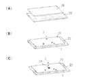
- FIGS. 4 (A) to 4 (C) An example is given in which the gallbladder wall and the duodenal wall are brought into close contact with each other by the anchor device 1.
- FIG. 4 (A) shows the gallbladder wall 20 and the duodenal wall 22.
- the anchor device 1 penetrates the duodenal wall 22 and the gallbladder wall 20, and connects the duodenal wall 22 and the gallbladder wall 20 in a state where the anchor device 1 itself is expanded.
- a plurality of locations (three locations in the figure) of the gallbladder wall 20 and the duodenal wall 22 are connected by an anchor device 1 and fixed to each other, and then a fistula 24 is formed as shown in FIG. 4 (C). In this state, bile is drained from the gallbladder into the duodenum.
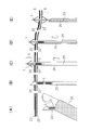
- FIGS. 5 (A) to 5 (E) an example of a procedure for joining two tissues using the anchor device 1 of the first embodiment of the present invention will be described in more detail.
- the ultrasonic endoscope 25 is omitted in order to clearly show the operation of the anchor device 1 and the ultrasonic endoscopic needle tube 26.
- the doctor inserts the ultrasonic endoscope 25 into the gastrointestinal tract through the patient's mouth and advances the gastrointestinal tract while observing with a monitor (FIG. 5 (A)).
- the gallbladder is visualized from the duodenal wall with an ultrasonic endoscope 25, the needle tube 26 of the endoscopic ultrasonographic puncture needle is passed through the forceps channel in the ultrasonic endoscope 25, and the duodenal wall 22 and the duodenal wall 22 and the needle tube 26 are passed through the needle tube 26. It penetrates the gallbladder wall 20 (FIG. 5 (B)).
- an extruded member such as a stylet 29 is advanced from the base end direction of the gastrointestinal endoscope 25 toward the tip end in the direction of the arrow, and the anchor device 1 is moved out from the inside of the needle tube 26.
- the first anchor portion 6 of the extruded anchor device 1 is autonomously expanded by elasticity or the like, and when the needle tube 26 is pulled back in the direction of the arrow, it is restricted to return through the hole formed in the gallbladder wall 20. (Fig. 5 (D)).
- the anchor device 1 is completely released from the needle tube 26, and the second anchor portion 8 of the anchor device 1 is also autonomously deployed by elasticity or the like.
- the anchor device 1 expanded in this way, the gallbladder wall 20 and the duodenal wall 22 are held between the first anchor portion 6 and the second anchor portion 8 of the anchor device 1 and are brought into close contact with each other and fixed to each other (FIG. 5). (E)).
- the needle tube 26 is collected in the gastrointestinal endoscope 25, and the gastrointestinal endoscope 25 is pulled back to the outside of the body. After repeating the procedure of FIGS.
- a fistula 24 is formed as shown in FIG. 4C, and a drainage tube is formed. By indwelling, the solution in the gallbladder is drained.
- the gastrointestinal endoscope 25 is advanced again in the gastrointestinal tract to the position of the anchor device 1, and the gastrointestinal endoscope 25
- a known gripping device such as a forceps or a snare housed inside is advanced outward from the tip of the digestive endoscope 25 to grip the second anchor portion 8 of the anchor device 1, and the gripping device is gripped by the digestive endoscope. Pull back toward the base tip of 25, and collect the anchor device 1 into the gastrointestinal endoscope 25.
- the anchor device 1 according to the first embodiment of the present invention will be described.
- (1) according to the anchor device 1 of the first embodiment, as compared with the conventional surgical operation, a plurality of tissues can be combined with less invasiveness and quickly, and no operator's skill is required. In addition, procedures such as fistula formation after joining a plurality of tissues become easier.
- the anchor device 1 of the first embodiment is formed of one member called a shaft 2, the structure is simple and it can be manufactured at low cost.
- the anchor device 1 of the first embodiment of the present invention can be deformed as follows.
- the number of each of the long anchor arm 7 of the first anchor portion 6 and the long anchor arm 9 of the second anchor portion 8 is not limited to two.
- the number of the long anchor arms 7 of the first anchor portion 6 and the long anchor arms 9 of the second anchor portion 8 may be three as shown in FIG. 6, or as shown in FIG. It may be four or five or more.
- each of the plurality of elongated anchor arms 7 of the first anchor portion 6 and the plurality of elongated anchor arms 9 of the second anchor portion 8 have a cross section of the shaft 2. Although they are provided corresponding to one arc divided into equal parts, the elongated anchor arms 7 and 9 may not be provided at equal intervals in the circumferential direction of the shaft 2. Further, the circumferential length of the elongated anchor arms 7 and 9 on the shaft 2 and the circumferential length of the portion of the shaft 2 between the adjacent elongated anchor arms 7 need not be the same. The circumferential length of the elongated anchor arms 7 and 9 in No. 2 and the circumferential length of the portion of the shaft 2 between the adjacent elongated anchor arms 7 and 9 need not be the same.
- the first end 4 and the second end 5 of the anchor device 1 may be sharpened. With such a configuration, the penetration of the anchor device 1 into the tissue becomes easier.
- the anchor device 1 may be asymmetric. For example, as shown in FIG. 9, the length of the first end portion 14 between the first end 4 and the first position 12 of the shaft 2 and the second end between the second end 5 and the second position 13 of the shaft 2. The lengths of the portions 15 may be different. According to such a configuration, one of the first end 4 and the second end 5 is the tip on the side through which the tissue is penetrated, and the other of the first end 4 and the second end 5 is the anchor device 1. It can be distinguished as the base end on the side closer to the operator.
- the long anchor arm 7 of the first anchor portion 6 and the long anchor arm 9 of the second anchor portion 8 have a symmetrical relationship, but the long anchor arm of the first anchor portion 6 7 and the elongated anchor arm 9 of the second anchor portion 8 may have different sizes and / or numbers.
- the lengths of the plurality of elongated anchor arms 7 of the first anchor portion 6 may be different, and each of the plurality of elongated anchor arms 9 of the second anchor portion 8 may be different. The length of may also be different.
- the plurality of elongated anchor arms 7 of the first anchor portion 6 and the plurality of elongated anchor arms 9 of the second anchor portion 8 are configured by cutting out the shaft 2 by a cutting means such as a laser processing device.
- a cutting means such as a laser processing device.
- the molding method of the plurality of elongated anchor arms 7 and 8 is not limited.
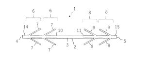
- a plurality of first anchor portions 6 may be provided along the shaft 2
- a plurality of second anchor portions 8 may be provided along the shaft 2.
- the shaft 2 of the first embodiment is hollow, the shaft 2 may be solid.
- each of the plurality of elongated anchor arms 7 of the first anchor portion 6 and the plurality of elongated anchor arms 9 of the second anchor portion 8 are the lengths of the shaft 2. It takes a maximum angle ⁇ of 90 ° with respect to the direction axis, but converges with respect to the elongated anchor arms 7 and 9 from the unfolding direction of the elongated anchor arms 7 and 9 (that is, the figure).
- the long anchor arm 7 has a direction from the second end 5 parallel to the longitudinal axis of the shaft 2 toward the first end 4, and the long anchor arm 9 has a third parallel to the longitudinal axis of the shaft 2.
- the elongated anchor arms 7 and 9 move to a position where ⁇ exceeds 90 °, preferably a position where ⁇ is 150 to 180 °.
- the elongated anchor arms 7 and 9 may be configured so as to be used. In this case, as shown in FIG. 5 (E), when the anchor device 1 is deployed to fix the gallbladder wall 20 and the duodenal wall 22 and then the anchor device 1 is pulled out from the tissue and collected, the second anchor portion 8 is used.
- the anchor device 1 of the first embodiment includes a tract organ other than the duodenum, a tract organ and a tract organ, a tract organ and a parenchymal organ, a parenchymal organ and a parenchymal organ, a mesothelium and a lumen organ, and a middle part. It can be used to connect two tissues such as the skin and parenchymal organs.
- the anchor device 100 for connecting a plurality of tissues is separated from the inner shaft 101 having a longitudinal axis and is mounted on the outer peripheral surface of the inner shaft 101.
- the first outer shaft 102 as a member
- the second outer shaft 103 as a second outer member
- the first anchor portion 106 and the second anchor portion 108 formed on the first outer shaft 102 and the second outer shaft 103, respectively.
- the first anchor portion 106 has a plurality of elongated anchor arms 107 that can be deployed toward the second anchor portion 108 in a direction away from the longitudinal axis of the first outer shaft 102
- the second anchor portion 106 has a second anchor.
- the portion 108 has a plurality of elongated anchor arms 109 that can be deployed toward the first anchor portion 106 in a direction away from the longitudinal axis of the second outer shaft 103.
- the plurality of elongated anchor arms 107 of the first anchor portion 106 are formed by cutting out the first outer shaft 102, and form a part of the first outer shaft 102.
- the plurality of elongated anchor arms 109 of the second anchor portion 108 are also formed of a portion obtained by cutting out the second outer shaft 103, and form a part of the second outer shaft 103.
- the distance d between the first position 112 of the first outer shaft 102 and the second position 113 of the second outer shaft 103 and the length L of each of the elongated anchor arms 107 and 109 shall be 2L ⁇ d. Is preferable.
- the first position 112 of the outer shaft 102 and the second position 113 of the outer shaft 103 are separated from the first end 104 of the outer shaft 102 and the second end 105 of the outer shaft 103.
- a first end portion 114 having a constant length exists between the first end 104 and the first position 112 of the outer shaft 102, and is constant between the second end 105 and the second position 113 of the outer shaft 103.
- the diameters of the inner shaft 101 and the outer shafts 102 and 103, the total length of the inner shaft 101, the distance d, and the length L of each of the elongated anchor arms 107 and 109 can be changed depending on the place of use and are not particularly limited.
- the total length of the inner shaft 101 may be 10-50 mm
- the distance d may be 8-45 mm
- the length L of each of the elongated anchor arms 107 and 109 may be 1-20 mm.
- the plurality of elongated anchor arms 107 of the first anchor portion 106 can be deployed in a direction away from the longitudinal axis of the shaft 102 toward the second anchor portion 108 with the first position 112 in the longitudinal direction of the shaft 102 as a base point. Is. Further, the plurality of elongated anchor arms 109 of the second anchor portion 108 are oriented away from the longitudinal axis of the shaft 103 toward the first anchor portion 106 with the second position 113 in the longitudinal direction of the shaft 102 as a base point. It is expandable.
- the outer shafts 102 and 103 have an expanded configuration, that is, a plurality of elongated anchor arms 107 of the first anchor portion 106 and a plurality of the second anchor portions 108.
- the outer shafts 102 and 103 have notch holes 110 and 111, respectively. Each exists.
- the materials of the shafts 101, 102, and 103 are not particularly limited, and for example, metals, metal alloys, thermoplastics, biodegradable resins, other medical grade materials, and the like can be used. Such a material is as described with respect to the anchor device 1 of the first embodiment.
- the outer shafts 102 and 103 are preferably self-expanding shafts having an expanded configuration when no external pressure is applied (also referred to as an open state or a free state).
- the self-expanding shaft can be manufactured using Nitinol or the like.
- Each of the outer shafts 102 and 103 of the anchor device 100 of the second embodiment includes anchor portions 106 and 108, and the length of one arc obtained by dividing the hollow substantially circular cross section into four equal parts is the anchor portions 6 and 8. Corresponds to the circumferential length of.
- the plurality of elongated anchor arms 107 of the first anchor portion 106 and the plurality of elongated anchor arms 109 of the second anchor portion 108 are substantially relative to the respective longitudinal axes of the outer shafts 102 and 103. It is also possible to take a parallel, contracted state.
- the plurality of elongated anchor arms 107 of the first anchor portion 106 and the plurality of elongated anchor arms 109 of the second anchor portion 108 are the longitudinal axes of the inner shaft 101 and the longitudinal directions of the outer shafts 102 and 103, respectively.
- the angle taken by the elongated anchor arms 107 and 109 with respect to the longitudinal axes of the outer shafts 102 and 103 decreases as pressure is applied to the anchor device 1.
- the outer shafts 102 and 103 of the anchor device 100 of the second embodiment have the first anchor portion when an external pressure is applied.
- the plurality of elongated anchor arms 107 of 106 and the plurality of elongated anchor arms 109 of the second anchor portion 108 are positioned along the longitudinal axis of the inner shaft 101 and the longitudinal axes of the outer shafts 102 and 103. be able to.
- the outer shafts 102 and 103 are manufactured from known materials such as metals, metal alloys, thermoplastics, biodegradable resins, and other medical grade materials, and the first anchor portion 106 and the anchor device 100 are manufactured. It can be manufactured by cutting a portion on the shaft 2 where the second anchor portion 108 is provided by a cutting means such as a known laser processing device.
- FIG. 4 and FIG. 4 show an example of a procedure for joining two tissues using the anchor device 100 of the second embodiment of the present invention and a procedure for joining two tissues using the anchor device 100 of the second embodiment of the present invention. This is as described in FIG.
- the anchor device 100 of the second embodiment of the present invention has the following effects in addition to the above-mentioned effects (1) and (2) of the anchor device 1 of the first embodiment.
- the anchor device 100 of the second embodiment has an inner shaft 101 and two outer shafts 102 and 103. Since it is formed from and, the strength along the longitudinal axis of the anchor device 1 increases.
- the anchor arms 107 and 109 can be formed on the entire circumference of the end faces of the outer shafts 102 and 103, the anchor arms are compared with the elongated anchor arms 7 and 9 of the first embodiment. The number and area of 7 and 9 can be increased.
- each of the plurality of elongated anchor arms 107 of the first anchor portion 106 and the plurality of elongated anchor arms 109 of the second anchor portion 108 is not limited as long as it is two or more.
- Each of the plurality of elongated anchor arms 107 of the first anchor portion 106 and the plurality of elongated anchor arms 109 of the second anchor portion 108 equally divided the cross sections of the first outer shaft 102 and the second outer shaft 103.
- the elongated anchor arms 107 and 109 may not be provided at equal intervals in the circumferential direction of the shaft 2.
- the circumferential length of the elongated anchor arms 107 and 109 on the shafts 102 and 103 does not match the circumferential length of the portion of the first outer shaft 102 between the adjacent elongated anchor arms 107. It may also be, and may not match the circumferential length of the portion of the second outer shaft 103 between the adjacent elongated anchor arms 109.
- Both ends of the inner shaft 101, the end 104 of the first outer shaft 102, and the end 105 of the second outer shaft 103 may be sharpened. With such a configuration, the penetration of the anchor device 100 into the tissue becomes easier.
- the anchor device 100 may be asymmetric.
- the length of the first end 114 between the end 104 of the first outer shaft 102 and the first position 112 and the length of the second end 115 between the first end 105 and the second position 113 of the second outer shaft 103. May be different. According to such a configuration, one of the end 104 and the end 105 can be distinguished as the tip on the side through which the tissue is penetrated, and the other as the base end on the side closer to the operator of the anchor device 100.
- the first end 114 and the second end 115 may be omitted, or members having any shape other than the shaft may be used as long as the long anchor arms 107 and 109 can be connected.
- the elongated anchor arm 107 of the first anchor portion 106 and the elongated anchor arm 109 of the second anchor portion 108 may have different sizes and / or numbers.
- the lengths of the plurality of elongated anchor arms 107 of the first anchor portion 106 may be different, and the lengths of the plurality of elongated anchor arms 109 of the second anchor portion 108 may be different. Good.
- a plurality of first anchor portions 106 may be provided along the inner shaft 101, and a plurality of second anchor portions 108 may be provided along the inner shaft 101.
- the plurality of elongated anchor arms 107 of the first anchor portion 106 and the plurality of elongated anchor arms 109 of the second anchor portion 108 have the first outer shaft 102 and the second outer shaft 103 of a laser processing device or the like, respectively. Although it was formed by cutting out by a cutting means or the like, the molding method of the plurality of long anchor arms 107 and 108 is not limited.
- the inner shaft 101 may be solid.
- each of the plurality of elongated anchor arms 107 of the first anchor portion 106 and the plurality of elongated anchor arms 109 of the second anchor portion 108 are outside. It takes a maximum angle of 90 ° with respect to the longitudinal axis of the shafts 102 and 103, but converges on the elongated anchor arms 107 and 109 from the unfolding direction of the elongated anchor arms 107 and 109.
- Direction that is, in FIG. 12, the long anchor arm 107 is in the direction from the second end 105 parallel to the longitudinal axis of the outer shaft 102 to the first end 104, and the long anchor arm 109 is in the outer shaft 103.
- the elongated anchor arms 107 and 109 When an external pressure is applied to the direction from the first end 104 parallel to the longitudinal axis to the second end 105), the elongated anchor arms 107 and 109 with respect to the longitudinal axes of the outer shafts 102 and 103, respectively.
- the elongated anchor arms 107 and 109 may be configured so that the position exceeding 90 °, preferably the position ⁇ is moved from 150 to 180 °.
- both the first anchor portion 106 and the second anchor portion 108 are used.
- the anchor device 1 is deployed in the direction opposite to the pulling direction, which makes it easier to collect the anchor device 100.
- the anchor device 100 of the second embodiment is not limited to gallbladder-duodenal bypass surgery.
- the anchor device 100 of the second embodiment includes a luminal organ other than the duodenum, a luminal organ and a tract organ, a luminal organ and a parenchymal organ, a parenchymal organ and a parenchymal organ, a mesothelium and a luminal organ, and a medium. It can be used to connect two tissues such as the skin and parenchymal organs.
- the present invention can also adopt the following configurations.
- An anchor device for connecting a plurality of tissues the shaft having a longitudinal axis and a first anchor portion and a second anchor portion each separated from each other and formed on the shaft.
- the 1 anchor portion has a plurality of elongated anchor arms that can be deployed in a direction away from the longitudinal axis of the shaft toward the second anchor portion with the first position of the shaft as a base point, and the second anchor portion is a shaft.
- An anchor device having a plurality of elongated anchor arms that can be deployed in a direction away from the longitudinal axis of the shaft toward the first anchor portion from the second position of the shaft.
- the plurality of elongated anchor arms of the first anchor portion and the plurality of elongated anchor arms of the second anchor portion take a contracted state at an angle of 0 to 10 ° with respect to the longitudinal axis of the shaft.
- the anchor device according to any one of (1) to (3).
- a plurality of elongated anchor arms of the first anchor portion and a plurality of elongated anchor arms of the second anchor portion can be deployed up to 45 ° with respect to the longitudinal axis of the shaft (1) to.
- the anchor device according to (7) preferably having a maximum of 90 °, more preferably a maximum of 75 °, and even more preferably a maximum of 45 °.
- the anchor device according to any one of (1) to (8), wherein the shaft contains a metal, a metal alloy, a thermoplastic plastic, or a biodegradable resin.
- (11) (I) Passing a needle tube through a forceps channel in an ultrasonic endoscope, penetrating two tissues with a needle tube, and an anchor device according to any one of (II) (1) to (10).
- a method of joining two tissues comprising pushing the two tissues out of the needle tube to deploy an anchor device, thereby holding the two tissues between the first anchor portion and the second anchor portion.
- An anchor device for connecting a plurality of tissues, the inner shaft having a longitudinal axis, the first outer member and the second outer member, which are separated from each other and mounted on the outer peripheral surface of the inner shaft.
- a first anchor portion and a second anchor portion formed on each of the first outer member and the second outer member are provided, and the first anchor portion is a longitudinal axis of the first outer member toward the second anchor portion.
- the second anchor portion has a plurality of elongated anchor arms that can be deployed in a direction away from the first anchor portion, and the second anchor portion can be deployed in a direction away from the longitudinal axis of the second outer member toward the first anchor portion.
- Anchor device with a shaped anchor arm.
- the plurality of elongated anchor arms of the first anchor portion and the plurality of elongated anchor arms of the second anchor portion are continuous parts of the first outer member and the second outer member, respectively.
- the plurality of elongated anchor arms of the first anchor portion and the plurality of elongated anchor arms of the second anchor portion are formed of cutout portions of the first outer member and the second outer member, respectively (12) or.
- the plurality of elongated anchor arms of the first anchor portion and the plurality of elongated anchor arms of the second anchor portion are 0 to 0 to each of the longitudinal axes of the first outer member and the second outer member.
- the anchor device according to any one of (12) to (14), which can take a contracted state forming an angle of 10 °.
- a plurality of elongated anchor arms of the first anchor portion and a plurality of elongated anchor arms of the second anchor portion have a maximum of 45 with respect to the respective longitudinal axes of the first outer member and the second outer member.
- the anchor device according to any one of (12) to (15), which can be deployed up to °.
- the plurality of elongated anchor arms of the first anchor portion can be deployed in a direction away from the longitudinal axis of the first outer member toward the second anchor portion with the first position of the first outer member as a base point.
- the plurality of elongated anchor arms of the second proposal car portion can be deployed in a direction away from the longitudinal axis of the second outer member toward the first anchor portion with the second position of the second outer member as a base point.
- the first position of the first outer member and the second position of the second outer member are any of (12) to (16) separated from the first end of the first outer member and the second end of the second outer member, respectively.
- Example 1 In order to fix the gastrointestinal tract walls to each other as easily and firmly as possible, the present inventor has developed a shaft-shaped anchor device having a plurality of pinnate protrusions (anchor arms), and the anchor device is used in a living pig body. The function was verified.
- an anchor device By securely fixing the gallbladder wall and gastrointestinal tract wall with an anchor device as a pretreatment for endoscopic ultrasonographic gallbladder drainage (EUS-GBD), the difficulty of EUS-GBD and the risk of complications after treatment are greatly increased. We propose a technique to lower it.
- EUS-GBD endoscopic ultrasonographic gallbladder drainage
- Anchor device 1 shown in the embodiment of FIG. 1 was designed using a nickel-titanium alloy for medical use. Since a biopsy needle (19 gauge, inner diameter of about 0.9 mm) is assumed for indwelling, a nickel-titanium alloy pipe material with a diameter of 0.84 mm and a length of 20 mm is used for smooth insertion, and a laser is used. The structure of the arm part was formed by cutting.
- the gallbladder was visualized from the stomach or duodenum using a convex EUS (GF-UCT260, Olympus), and the EUS-FNA biopsy needle (EZ Shot 3 Plus, Olympus) from which the stylet was removed was used from the stomach. Puncture the gallbladder wall. Insert the anchor device from the hand side of the biopsy needle using a special auxiliary tool, and push it to the needle tip using a stylet. At the tip of the biopsy needle in the gallbladder, confirm on the fluoroscopic screen and the EUS screen that the anchor arm on the distal side of the anchor device is fully deployed.
- GF-UCT260 convex EUS
- EUS-FNA biopsy needle EZ Shot 3 Plus, Olympus
- the biopsy needle While pressing the tip of the EUS, slowly pull the biopsy needle to bring the distal side of the anchor device into contact with the gallbladder wall.
- the anchor arm of the anchor device on the proximal side expands.
- FIG. 15 A tail tube, 7Fr, 150 mm custom-made product, Forte Glow Medical Co., Ltd. was placed (Fig. 15 (A)).
- reference numeral 1 two shown is an anchor device
- reference numeral 25 is an endoscope
- reference numeral 30 is a guide wire
- reference numeral 32 is a dilator
- reference numeral 40 is a gallbladder
- reference numeral 42 is a reference numeral 42.
- the stomach wall is an anchor device
- reference numeral 25 is an endoscope
- reference numeral 30 is a guide wire
- reference numeral 32 is a dilator
- reference numeral 40 is a gallbladder
- reference numeral 42 is a reference numeral 42.
- the stomach wall is an anchor device
- reference numeral 25 is an endoscope
- reference numeral 30 is a guide wire
- reference numeral 32 is a dilator
- reference numeral 40 is a gallbladder
- reference numeral 42 is a reference numeral 42
Landscapes
- Health & Medical Sciences (AREA)
- Surgery (AREA)
- Life Sciences & Earth Sciences (AREA)
- Nuclear Medicine, Radiotherapy & Molecular Imaging (AREA)
- Molecular Biology (AREA)
- Public Health (AREA)
- Engineering & Computer Science (AREA)
- Biomedical Technology (AREA)
- Heart & Thoracic Surgery (AREA)
- Medical Informatics (AREA)
- Veterinary Medicine (AREA)
- Animal Behavior & Ethology (AREA)
- General Health & Medical Sciences (AREA)
- Vascular Medicine (AREA)
- Reproductive Health (AREA)
- Physiology (AREA)
- Gynecology & Obstetrics (AREA)
- Radiology & Medical Imaging (AREA)
- Oral & Maxillofacial Surgery (AREA)
- Pathology (AREA)
- Media Introduction/Drainage Providing Device (AREA)
- Surgical Instruments (AREA)
Priority Applications (3)
| Application Number | Priority Date | Filing Date | Title |
|---|---|---|---|
| JP2021509348A JP7549353B2 (ja) | 2019-03-22 | 2020-03-19 | アンカー器具 |
| EP20777739.2A EP3943015A4 (en) | 2019-03-22 | 2020-03-19 | ANCHOR INSTRUMENT |
| US17/441,557 US20220167991A1 (en) | 2019-03-22 | 2020-03-19 | Anchor device |
Applications Claiming Priority (2)
| Application Number | Priority Date | Filing Date | Title |
|---|---|---|---|
| JP2019-054027 | 2019-03-22 | ||
| JP2019054027 | 2019-03-22 |
Publications (1)
| Publication Number | Publication Date |
|---|---|
| WO2020196336A1 true WO2020196336A1 (ja) | 2020-10-01 |
Family
ID=72611940
Family Applications (1)
| Application Number | Title | Priority Date | Filing Date |
|---|---|---|---|
| PCT/JP2020/012490 Ceased WO2020196336A1 (ja) | 2019-03-22 | 2020-03-19 | アンカー器具 |
Country Status (4)
| Country | Link |
|---|---|
| US (1) | US20220167991A1 (enExample) |
| EP (1) | EP3943015A4 (enExample) |
| JP (1) | JP7549353B2 (enExample) |
| WO (1) | WO2020196336A1 (enExample) |
Cited By (10)
| Publication number | Priority date | Publication date | Assignee | Title |
|---|---|---|---|---|
| WO2022225932A1 (en) * | 2021-04-20 | 2022-10-27 | G.I.Windows, Inc. | Mechanism to create enterotomy between one or more compression deivces |
| US11751877B2 (en) | 2018-06-02 | 2023-09-12 | G.I. Windows, Inc. | Systems, devices, and methods for forming anastomoses |
| US11864764B2 (en) | 2021-04-20 | 2024-01-09 | G.I. Windows, Inc. | Systems, devices, and methods for endoscope or laparoscopic magnetic navigation |
| US11864767B2 (en) | 2010-01-05 | 2024-01-09 | G.I. Windows, Inc. | Self-assembling magnetic anastomosis device having an exoskeleton |
| US11998207B2 (en) | 2010-01-05 | 2024-06-04 | G.I. Windows, Inc. | Methods and apparatus for magnet-induced compression anastomosis between adjacent organs |
| US12053181B2 (en) | 2022-09-02 | 2024-08-06 | G.I. Windows, Inc. | Systems, devices, and methods for endoscope or laparoscope magnetic navigation |
| US12070217B2 (en) | 2022-09-01 | 2024-08-27 | G.I. Windows, Inc. | Pressure profile magnetic compression anastomosis devices |
| US12201300B2 (en) | 2022-08-05 | 2025-01-21 | G.I. Windows, Inc. | Magnetic compression anastomosis device with multipiece vertebra |
| US12256932B2 (en) | 2015-03-12 | 2025-03-25 | G.I. Windows, Inc. | Magnetic anastomosis devices with varying magnetic force at a distance |
| US12502174B2 (en) | 2023-10-27 | 2025-12-23 | G.I. Windows, Inc. | Systems, devices, and methods for forming anastomoses |
Citations (3)
| Publication number | Priority date | Publication date | Assignee | Title |
|---|---|---|---|---|
| JP2003509175A (ja) * | 1999-09-20 | 2003-03-11 | アプリヴァ メディカル、 インク. | 体の菅腔を閉鎖する方法と装置 |
| US20080228199A1 (en) * | 2007-03-16 | 2008-09-18 | Ethicon Endo-Surgery, Inc. | Endoscopic tissue approximation method |
| JP4456482B2 (ja) * | 2002-08-29 | 2010-04-28 | ボストン サイエンティフィック リミテッド | 組織係止具並びに関連した展開システム及び方法 |
Family Cites Families (10)
| Publication number | Priority date | Publication date | Assignee | Title |
|---|---|---|---|---|
| US6231561B1 (en) * | 1999-09-20 | 2001-05-15 | Appriva Medical, Inc. | Method and apparatus for closing a body lumen |
| CA2445281C (en) * | 2001-04-27 | 2013-07-16 | Myomend, Inc. | Prevention of myocardial infarction induced ventricular expansion and remodeling |
| US20070129755A1 (en) * | 2005-12-05 | 2007-06-07 | Ovalis, Inc. | Clip-based systems and methods for treating septal defects |
| CA2532882A1 (en) * | 2003-07-11 | 2005-01-20 | Endogun Medical Systems Ltd. | Surgical fasteners and devices for surgical fastening |
| DE102004022590A1 (de) * | 2004-05-07 | 2005-12-01 | Feussner, Hubertus, Prof.Dr.med. | Blindniet zur Adaption von biologischem Gewebe und Vorrichtung zum Setzen des selbigen, insbesondere durch den Instrumentenkanal eines Endoskops |
| CA2621197A1 (en) * | 2005-09-01 | 2007-03-08 | Cordis Corporation | Patent foramen ovale closure method |
| US8192461B2 (en) * | 2008-09-11 | 2012-06-05 | Cook Medical Technologies Llc | Methods for facilitating closure of a bodily opening using one or more tacking devices |
| US9980708B2 (en) * | 2010-01-20 | 2018-05-29 | Micro Interventional Devices, Inc. | Tissue closure device and method |
| US10398445B2 (en) * | 2011-01-11 | 2019-09-03 | Amsel Medical Corporation | Method and apparatus for clamping tissue layers and occluding tubular body structures |
| US10687805B2 (en) * | 2015-08-11 | 2020-06-23 | Amsel Medical Corporation | Apparatus and methods for clamping tissue layers and occluding hollow vessels |
-
2020
- 2020-03-19 EP EP20777739.2A patent/EP3943015A4/en active Pending
- 2020-03-19 US US17/441,557 patent/US20220167991A1/en active Pending
- 2020-03-19 JP JP2021509348A patent/JP7549353B2/ja active Active
- 2020-03-19 WO PCT/JP2020/012490 patent/WO2020196336A1/ja not_active Ceased
Patent Citations (3)
| Publication number | Priority date | Publication date | Assignee | Title |
|---|---|---|---|---|
| JP2003509175A (ja) * | 1999-09-20 | 2003-03-11 | アプリヴァ メディカル、 インク. | 体の菅腔を閉鎖する方法と装置 |
| JP4456482B2 (ja) * | 2002-08-29 | 2010-04-28 | ボストン サイエンティフィック リミテッド | 組織係止具並びに関連した展開システム及び方法 |
| US20080228199A1 (en) * | 2007-03-16 | 2008-09-18 | Ethicon Endo-Surgery, Inc. | Endoscopic tissue approximation method |
Non-Patent Citations (2)
| Title |
|---|
| JOURNAL OF HEPATO-BILIARY-PANCREATIC SCIENCES, vol. 25, no. 1, 2018, pages 87 - 95 |
| See also references of EP3943015A4 |
Cited By (12)
| Publication number | Priority date | Publication date | Assignee | Title |
|---|---|---|---|---|
| US11864767B2 (en) | 2010-01-05 | 2024-01-09 | G.I. Windows, Inc. | Self-assembling magnetic anastomosis device having an exoskeleton |
| US11998207B2 (en) | 2010-01-05 | 2024-06-04 | G.I. Windows, Inc. | Methods and apparatus for magnet-induced compression anastomosis between adjacent organs |
| US12256932B2 (en) | 2015-03-12 | 2025-03-25 | G.I. Windows, Inc. | Magnetic anastomosis devices with varying magnetic force at a distance |
| US11751877B2 (en) | 2018-06-02 | 2023-09-12 | G.I. Windows, Inc. | Systems, devices, and methods for forming anastomoses |
| US12426884B2 (en) | 2018-06-02 | 2025-09-30 | G.I. Windows, Inc. | Systems, devices, and methods for forming anastomoses |
| WO2022225932A1 (en) * | 2021-04-20 | 2022-10-27 | G.I.Windows, Inc. | Mechanism to create enterotomy between one or more compression deivces |
| US11864764B2 (en) | 2021-04-20 | 2024-01-09 | G.I. Windows, Inc. | Systems, devices, and methods for endoscope or laparoscopic magnetic navigation |
| US12070212B2 (en) | 2021-04-20 | 2024-08-27 | G.I. Windows, Inc. | Systems, devices, and methods for endoscope or laparoscopic magnetic navigation |
| US12201300B2 (en) | 2022-08-05 | 2025-01-21 | G.I. Windows, Inc. | Magnetic compression anastomosis device with multipiece vertebra |
| US12070217B2 (en) | 2022-09-01 | 2024-08-27 | G.I. Windows, Inc. | Pressure profile magnetic compression anastomosis devices |
| US12053181B2 (en) | 2022-09-02 | 2024-08-06 | G.I. Windows, Inc. | Systems, devices, and methods for endoscope or laparoscope magnetic navigation |
| US12502174B2 (en) | 2023-10-27 | 2025-12-23 | G.I. Windows, Inc. | Systems, devices, and methods for forming anastomoses |
Also Published As
| Publication number | Publication date |
|---|---|
| US20220167991A1 (en) | 2022-06-02 |
| JPWO2020196336A1 (enExample) | 2020-10-01 |
| EP3943015A4 (en) | 2022-12-07 |
| JP7549353B2 (ja) | 2024-09-11 |
| EP3943015A1 (en) | 2022-01-26 |
Similar Documents
| Publication | Publication Date | Title |
|---|---|---|
| WO2020196336A1 (ja) | アンカー器具 | |
| US12138150B2 (en) | Methods and devices for minimally invasive transcatheter coronary artery bypass grafting | |
| US20250312058A1 (en) | Intraluminal tissue modifying systems and associated devices and methods | |
| US11751877B2 (en) | Systems, devices, and methods for forming anastomoses | |
| US20250160839A1 (en) | Devices and methods for forming an anastomosis | |
| ES2538992T3 (es) | Dispositivos para cerrar el apéndice auricular izquierdo | |
| US10575837B2 (en) | Tissue and vascular closure devices and methods of use thereof | |
| JP2020171796A (ja) | 胆管ステント | |
| US8721679B2 (en) | Apparatus and method for closing an opening in a blood vessel using a permanent implant | |
| JP5224298B2 (ja) | 管腔壁穿刺用オーバーチューブ | |
| US20220323731A1 (en) | Systems and methods for percutaneous body lumen drainage | |
| JP2017159055A (ja) | 非半径方向の圧着を有する部分円周状ステント | |
| JP2008517677A (ja) | 医療デバイス送出カテーテル | |
| US20240041461A1 (en) | Mechanism to create enterotomy between one or more compression devices | |
| AU2021427747A1 (en) | A compression anastomosis system, and use thereof | |
| JP2009543660A (ja) | 乳頭拡張器 | |
| JP2024516145A (ja) | 磁気吻合圧縮装置を送りかつ位置決めし、次いで吻合部を形成するためのシステム、装置および方法 | |
| JP2012500098A (ja) | 経管腔的処置中にリンパ節を切除する又は組織へ錨着するための器具 | |
| JP3560931B2 (ja) | 内視鏡挿入補助具 | |
| JP2021159392A (ja) | 内視鏡用カテーテル | |
| JP5912473B2 (ja) | マイクロスネークリトラクター | |
| JP2018157914A (ja) | スコアリングデバイスおよびスコアリングデバイスの操作方法 | |
| US12502174B2 (en) | Systems, devices, and methods for forming anastomoses | |
| US20240148381A1 (en) | Systems, devices, and methods for forming anastomoses | |
| CN120500301A (zh) | 医疗系统和装置 |
Legal Events
| Date | Code | Title | Description |
|---|---|---|---|
| 121 | Ep: the epo has been informed by wipo that ep was designated in this application |
Ref document number: 20777739 Country of ref document: EP Kind code of ref document: A1 |
|
| DPE1 | Request for preliminary examination filed after expiration of 19th month from priority date (pct application filed from 20040101) | ||
| ENP | Entry into the national phase |
Ref document number: 2021509348 Country of ref document: JP Kind code of ref document: A |
|
| NENP | Non-entry into the national phase |
Ref country code: DE |
|
| WWE | Wipo information: entry into national phase |
Ref document number: 2020777739 Country of ref document: EP |