WO2020196209A1 - 副室式内燃機関 - Google Patents
副室式内燃機関 Download PDFInfo
- Publication number
- WO2020196209A1 WO2020196209A1 PCT/JP2020/012159 JP2020012159W WO2020196209A1 WO 2020196209 A1 WO2020196209 A1 WO 2020196209A1 JP 2020012159 W JP2020012159 W JP 2020012159W WO 2020196209 A1 WO2020196209 A1 WO 2020196209A1
- Authority
- WO
- WIPO (PCT)
- Prior art keywords
- chamber
- sub
- injection port
- main chamber
- passage
- Prior art date
- Legal status (The legal status is an assumption and is not a legal conclusion. Google has not performed a legal analysis and makes no representation as to the accuracy of the status listed.)
- Ceased
Links
Images





Classifications
-
- F—MECHANICAL ENGINEERING; LIGHTING; HEATING; WEAPONS; BLASTING
- F02—COMBUSTION ENGINES; HOT-GAS OR COMBUSTION-PRODUCT ENGINE PLANTS
- F02B—INTERNAL-COMBUSTION PISTON ENGINES; COMBUSTION ENGINES IN GENERAL
- F02B19/00—Engines characterised by precombustion chambers
- F02B19/12—Engines characterised by precombustion chambers with positive ignition
-
- F—MECHANICAL ENGINEERING; LIGHTING; HEATING; WEAPONS; BLASTING
- F02—COMBUSTION ENGINES; HOT-GAS OR COMBUSTION-PRODUCT ENGINE PLANTS
- F02B—INTERNAL-COMBUSTION PISTON ENGINES; COMBUSTION ENGINES IN GENERAL
- F02B19/00—Engines characterised by precombustion chambers
- F02B19/16—Chamber shapes or constructions not specific to sub-groups F02B19/02 - F02B19/10
- F02B19/18—Transfer passages between chamber and cylinder
-
- Y—GENERAL TAGGING OF NEW TECHNOLOGICAL DEVELOPMENTS; GENERAL TAGGING OF CROSS-SECTIONAL TECHNOLOGIES SPANNING OVER SEVERAL SECTIONS OF THE IPC; TECHNICAL SUBJECTS COVERED BY FORMER USPC CROSS-REFERENCE ART COLLECTIONS [XRACs] AND DIGESTS
- Y02—TECHNOLOGIES OR APPLICATIONS FOR MITIGATION OR ADAPTATION AGAINST CLIMATE CHANGE
- Y02T—CLIMATE CHANGE MITIGATION TECHNOLOGIES RELATED TO TRANSPORTATION
- Y02T10/00—Road transport of goods or passengers
- Y02T10/10—Internal combustion engine [ICE] based vehicles
- Y02T10/12—Improving ICE efficiencies
Definitions
- the present disclosure relates to a sub-chamber internal combustion engine that transmits power by a crankshaft.
- a sub-chamber type internal combustion engine having a main chamber (main combustion chamber) and a sub-chamber (sub-combustion chamber) connected to the main chamber via a communication passage
- a sub-chamber internal combustion engine an air-fuel mixture is formed from the fuel injected into the main chamber.
- the formed air-fuel mixture is supplied to the sub chamber via the communication passage during compression, and is ignited by the spark plug in the sub chamber.
- a flame is formed.
- the flame formed in the sub-chamber is jetted into the main chamber through the continuous passage and ignites the air-fuel mixture in the main chamber.
- the flame propagation distance of the main chamber is shortened by optimizing the direction of the plurality of passages (injection ports) connecting the main chamber and the sub chamber according to the shape of the combustion chamber.
- a technique for further improving thermal efficiency is disclosed.
- the first injection port in which the central axis of the injection port points to the inner wall surface of the cylinder bore and the injection port when the piston is arranged near the compression top dead center.
- the first injection port and the second injection port are arranged at equal intervals around the central axis of the sub chamber, and are arranged alternately in the circumferential direction.
- the combustion of the air-fuel mixture in the crankshaft direction region (spatial region S shown in FIG. 2) of the main chamber becomes slower than in other regions. If unburned gas remains due to the delay in combustion in the main chamber, the amount of HC (Hydro Carbon) and soot generated may increase, and the combustion state of the main chamber may vary.
- the embodiment of the present disclosure relates to a sub-chamber internal combustion engine in which the combustion state of the main chamber is homogenized.
- the sub-chamber internal combustion engine transmits power by a crankshaft.
- the sub-chamber internal combustion engine includes a main chamber, a sub-chamber, a communication passage, and an ignition unit.
- the main chamber is defined by a cylinder, a cylinder head, and a piston.
- the sub chamber projects from the cylinder head toward the main chamber and is separated from the main chamber.
- the communication passage connects the main room and the sub room.
- the ignition unit ignites the air-fuel mixture introduced from the main chamber to the sub chamber via the communication passage.
- the communication passage includes a first passage and a second passage having a first injection port and a second injection port for injecting a flame generated in the sub chamber by ignition toward the main chamber, respectively.
- the first injection port is arranged along the crankshaft direction.
- the second injection port is arranged along a direction different from the crankshaft direction, and the opening area of the second injection port is smaller than the opening area of the first injection port.
- the first injection port of the first passage for injecting flame is arranged along the crankshaft direction of the cylinder.
- the flame reaches the space region in the crankshaft direction of the cylinder in the main chamber, and combustion in this space region is promoted.
- an intake valve and an exhaust valve are often arranged in a direction orthogonal to the crankshaft direction of the cylinder. Therefore, in the space region in the crankshaft direction of the cylinder, the ceiling formed by the cylinder head is at a higher position than other space regions (the space region in the direction orthogonal to the crankshaft direction of the cylinder), and the space volume is increased. growing.
- the second injection port of the second passage is arranged along a direction different from the crankshaft direction of the cylinder, and the opening area of the second injection port is smaller than the opening area of the first injection port.
- the first passage sends a flame to a space region larger than the other space region, while the second passage sends a flame smaller than the flame injected from the first passage to another space region. That is, each of the first passage and the second passage sends out a flame suitable for the size of the space area. Therefore, a more homogeneous combustion state of the main chamber is realized.
- the cylinder head may have a plurality of surfaces inclined with respect to the cylinder axial direction. Then, the first injection port may be configured so that the flame propagates along the ridgeline where the plurality of slopes of the cylinder head intersect.
- the flame sent from the first continuous passage to the main chamber surely reaches the space region in the main chamber where the space in the vertical direction in the ridge direction of the cylinder is the largest. As a result, combustion in this spatial region is promoted.
- the first continuous passage surely sends out the flame to the region where the space in the vertical direction formed by the cylinder head and the piston is the largest. Further, since it is prevented that the flame immediately after being sent out from the first continuous passage directly hits the cylinder head, the occurrence of heat loss is prevented. As a result, the combustion efficiency in the space region in the crankshaft direction in the main chamber is increased.
- the opening area of the first passage may increase from the sub room to the main room.
- the flame sent from the first passage to the main room becomes even larger. Therefore, the contact area between the air-fuel mixture and the flame in a large space region in the crankshaft direction of the cylinder is expanded. As a result, combustion in a large space region in the crankshaft direction is promoted.
- the vertical sectional view which shows the schematic structure of the auxiliary chamber type internal combustion engine by one Embodiment of this disclosure.
- the cross-sectional view which shows the formation part of the communication passage of the auxiliary chamber type internal combustion engine of FIG.
- FIG. 1 is a vertical cross-sectional view perpendicular to the crankshaft direction showing a forming portion of a communication passage of the sub-chamber internal combustion engine and a flame injection state of FIG.
- a vertical cross-sectional view perpendicular to the left-right direction showing a forming portion of a communication passage of the sub-chamber internal combustion engine and a flame injection state of FIG.
- the sub-chamber internal combustion engine 1 has a main chamber 4, a sub-chamber 6 adjacent to the main chamber 4, a plurality of passages 8 communicating the main chamber 4 and the sub-chamber 6, and ignition.
- a plug (an example of an ignition unit) 10 and a fuel injection valve 12 are provided.
- the sub-chamber internal combustion engine 1 is an in-line internal combustion engine in which a plurality of cylinders N including a main chamber 4 and a sub chamber 6 are arranged in series. That is, the main chamber 4, the sub chamber 6, the plurality of communication passages 8, the spark plug 10, and the fuel injection valve 12 are provided in each cylinder N.
- the arrangement of the cylinders N is not limited to this, and may be a V type or a horizontally opposed type.
- the main chamber 4 is a space defined by the cylinder 101a of the cylinder block 101, the cylinder head 102, and the piston 103.
- the main chamber 4 has a pent roof shape, and the cylinder head 102 has two slopes inclined with respect to the cylinder axis, extending toward the intake port 105 side and the exhaust port 110 side.
- the main chamber 4 is connected to the intake port 105 via an intake valve 104 driven by an intake cam (not shown).
- the intake port 105 is connected to an intake passage, a throttle valve, and an air cleaner (not shown).
- the main chamber 4 is connected to an exhaust port 110, an exhaust passage (not shown), and an exhaust purification catalyst (not shown) via an exhaust valve 109 driven by an exhaust cam (not shown).
- the sub-chamber internal combustion engine 1 transmits power to a power transmission device such as a transmission by a crankshaft (not shown).
- the piston 103 drives the crankshaft via a connecting rod (not shown).
- the sub chamber 6 is provided at the top of the pent roof shape of the main chamber 4 and is adjacent to the main chamber 4.
- the sub-chamber 6 is a space defined by the sub-chamber wall 61.
- the sub chamber 6 projects from the cylinder head 102 toward the main chamber 4 and is separated from the main chamber 4 by the sub chamber wall 61.
- the sub chamber 6 is provided substantially at the center of the line of intersection (ridge line L) of the two slopes of the main chamber 4 having a pent roof shape.
- the sub chamber 6 has the same center X1 as the main chamber 4.
- the auxiliary chamber wall 61 has a circular cross section, and the bottom portion 61a is formed in a hemispherical shape.
- the volume of the sub chamber 6 is smaller than that of the main chamber 4, and the flame of the air-fuel mixture ignited by the spark plug 10 quickly propagates into the sub chamber 6.
- a plurality of communication passages 8 are provided at the bottom 61a of the sub chamber wall 61.
- the communication passage 8 guides the air-fuel mixture of the main chamber 4 to the sub chamber 6. Further, when the air-fuel mixture introduced into the sub-chamber 6 is ignited by the spark plug 10, the communication passage 8 sends out the flame of the air-fuel mixture in the sub-chamber 6 to the main chamber 4.
- the communication passage 8 has an injection port 8a facing the main chamber 4 on the outer peripheral surface of the sub chamber wall 61, and an introduction port 8b facing the sub chamber 6 on the inner peripheral surface of the sub chamber wall 61.
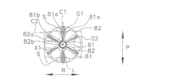
- the communication passage 8 of the present embodiment has two first passages 81 provided in the crankshaft direction P and four second passages 82 provided between the two first passages 81. The opening area of the first passage 81 is larger than the opening area of the second passage 82.
- the flame G1 injected from the first injection port 81a is the lower surface of the cylinder head 102 (with the piston 103).
- the first communication passage 81 so as to overlap the ridge line L (the intersection of two pent roof-shaped slopes of the main chamber 4) formed on the facing surfaces), that is, so that the flame G1 propagates along the ridge line L. Is arranged.
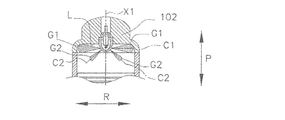
- FIGS. 3B and 3C when viewed from the left-right direction R or the crankshaft direction P, the position is higher in the vertical direction than the flame G2 injected from the second injection port 82a of the second passage 82.
- the first passage 81 is arranged so that the flame G1 is sent out toward. Further, since the opening area of the first passage 81 is larger than the opening area of the second passage 82, the flame G1 is larger than the flame G2.
- the air-fuel mixture in the space region S in the crankshaft direction P. Burns slower than in other areas. That is, when the lower surface of the cylinder head 102 has a pent roof shape, the left-right direction R of the main chamber 4 has a downward slope from the center X1 toward the outer circumference. On the other hand, the crankshaft direction P of the main chamber 4 does not have such a gradient. Therefore, there is a large difference in the vertical space volume formed by the cylinder head 102 and the piston 103.
- the first continuous passage 81 of the present embodiment has a first injection port 81a and an introduction port 81b.
- the first injection port 81a and the introduction port 81b are provided so as to face each other on a line extending radially from the center X1 of the main chamber 4 and the sub chamber 6. Further, the opening area from the first injection port 81a to the introduction port 81b is constant. Further, the first injection port 81a and the introduction port 81b are provided at the same height. As a result, the central axis C1 of the first passage 81 extends in the direction orthogonal to the vertical direction in the crankshaft direction P passing through the center X1.
- the central axis C1 does not intersect the ridge line L in the main chamber 4 in the vertical direction.
- the ridge line L and the central axis C1 overlap each other, and the first injection port 81a faces the direction along the ridge line L.
- the first communication passage 81 injects the flame G1 in the direction along the central axis C1. Therefore, the flame G1 is injected toward the crankshaft direction P of the main chamber 4, that is, the space region S having a large space volume.
- the flame G2 injected from the second injection port 82a when viewed from the vertical direction (the piston 103 side in the cylinder axial direction Q) is sent out in a direction different from at least the first continuous passage 81.
- the second passage 82 is arranged. Further, as shown in FIGS. 3B and 3C, the position is lower in the vertical direction than the flame G1 injected from the first injection port 81a of the first continuous passage 81 when viewed from the left-right direction R or the crankshaft direction P.
- the second passage 82 is arranged so that the flame G2 is sent out toward the direction. That is, the second passage 82 is arranged so as to extend in the direction toward the piston 103 from the first passage 81. Further, since the opening area of the second passage 82 is smaller than the opening area of the first passage 81, the flame G2 is smaller than the flame G1.
- the second continuous passage 82 of the present embodiment has a second injection port 82a and a second introduction port 82b.
- the second injection port 82a and the second introduction port 82b are provided so as to face each other on a line extending radially from the center X1 of the main chamber 4 and the sub chamber 6. Further, as shown in FIGS. 3B and 3C, the opening area from the second injection port 82a to the second introduction port 82b is constant, and the second injection port 82a is located lower than the second introduction port 82b in the vertical direction. Provided.
- the central axis C2 of the second passage 82 passes through the center X1 and extends in a direction inclined by a predetermined angle with respect to a direction orthogonal to the vertical direction. It is preferable that the central axis C2 does not intersect the lower surface of the cylinder head 102 (that is, the slope of the pent roof shape) in the main chamber 4 in the vertical direction. In other words, as shown in FIG. 3B, it is preferable that the second injection port 82a faces the direction along the slope of the pent roof shape when viewed from the extending direction of the ridge line L. As shown in FIG.
- the second passage 82 injects the flame G2 in the direction along the central axis C2. Therefore, the flame G2 is evenly ejected toward the left-right direction R of the main chamber 4, that is, a region different from the space region S.
- the second passage 82 may be further arranged below the first passage 81. In this case, the flame G1 promotes combustion in the upper region with respect to the space region S having a large space volume, whereas the flame G2 promotes combustion in the lower region.
- the spark plug 10 is arranged at the center X1 of the sub chamber 6. The spark plug 10 ignites the air-fuel mixture in the sub chamber 6.
- the fuel injection valve 12 is provided toward the main chamber 4. Further, the fuel injection valve 12 is provided outside the sub chamber 6. In the present embodiment, the fuel injection valve 12 injects fuel directly into the main chamber 4. That is, the sub-chamber internal combustion engine 1 is a direct injection type internal combustion engine. In the fuel injection valve 12, the injection amount and the injection timing are controlled by a control unit (not shown). Further, the fuel injection valve 12 is connected to a fuel injection pump (not shown) and a fuel tank. The fuel injection valve 12 is arranged on the intake valve 104 side of the cylinder head 102. In the present embodiment, the target air-fuel ratio is set to a value leaner than the theoretical air-fuel ratio. That is, the sub-chamber internal combustion engine 1 is operated by lean burn. This improves fuel efficiency.
- the intake valve 104 in the intake stroke, the intake valve 104 is opened, the piston 103 is lowered, and the intake air flows into the main chamber 4 and the sub-chamber 6.
- the intake air is pressurized by a supercharger (not shown).
- the pressure in the main chamber 4 and the sub chamber 6 becomes the same as the pressure of the intake air.
- the fuel injection valve 12 is controlled so as to mainly perform fuel injection for supplying fuel to the main chamber 4.
- the injected fuel mixes with the intake air in the main chamber 4 to form an air-fuel mixture.
- the air-fuel mixture is supplied to the entire main chamber 4.
- the intake valve 104 closes and the piston 103 rises, compressing the air-fuel mixture in the main chamber 4. At this time, the pressure in the main chamber 4 rises.
- the piston 103 rises in the compression stroke the air-fuel mixture is introduced from the main chamber 4 to the sub chamber 6 via the communication passage 8. At this time, the air-fuel mixture is introduced into the sub-chamber 6 by the communication passage 8.
- the first injection port 81a of the first communication passage 81 for injecting the flame G1 is arranged along the crankshaft direction P of the cylinder 101a.
- the flame G1 reaches the space region S in the crankshaft direction P of the cylinder 101a in the main chamber 4, and combustion in this space region S is promoted.
- the intake valve 104 and the exhaust valve 109 are often arranged in the direction orthogonal to the crankshaft direction P of the cylinder 101a.
- the ceiling formed by the cylinder head 102 is located higher than the other space regions (the space region in the direction orthogonal to the crankshaft direction P of the cylinder 101a). And the space volume becomes large.
- the second injection port 82a of the second passage 82 is arranged along a direction different from the crankshaft direction P of the cylinder 101a, and the opening area of the second injection port 82a is larger than the opening area of the first injection port 81a. Is also small.
- the first passage 81 sends out the flame G1 to the space region S larger than the other space regions, while the second passage 82 sends the flame G2 smaller than the flame G1 ejected from the first passage 81.
- the first passage 81 and the second passage 82 send out the flame G1 and the flame G2 that match the size of the space region, respectively. Therefore, a more homogeneous combustion state of the main chamber 4 is realized.
- the sub-chamber internal combustion engine 1 is a direct injection type internal combustion engine, but the present disclosure is not limited to this.
- it may be an auxiliary chamber type internal combustion engine provided with an intake port injector provided at the intake port 105.
- the sub chamber 6 is provided in the same center X1 as the main chamber 4, but the present disclosure is not limited to this.
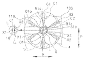
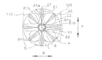
- the sub chamber 6 is provided at the center X2 offset in the direction intersecting the ridge line L from the center X1 of the main chamber 4 toward the inner wall surface of the cylinder 101a. May be good.
- the first line C1 of the first passage 81 extending from the center X2 approaches the ridge line L passing through the center X1.
- the injection port 81a and the first introduction port 81b are arranged.
- the central axis C1 of the first continuous passage 81 becomes a straight line LL extending parallel to the ridge line L through the center X2 offset in the direction intersecting the ridge line L from the center X1.
- it tilts toward the ridgeline L side.
- the inclination angle of the central axis C1 changes according to the offset amount.
- the central axis C1 of the first passage 8 takes in air with respect to the straight line LL passing through the center X2. Tilt to the port 105 side.
- the first injection port 81a is provided on the intake side of the first introduction port 81b.
- the opening area of the first passage 81 is constant from the first injection port 81a to the introduction port 81b, but the present disclosure is not limited to this.
- four second passages 82 are provided, the present disclosure is not limited thereto.
- the present disclosure is not limited thereto.
- six second passages 82 are provided, and the six second passages 82 are 8 on the same circumference centered on the sub-chamber 6 located substantially in the center of the main chamber 4. It may be equally divided and may be arranged at a position other than the crankshaft direction P where the two first passages 81 are arranged.
- the opening area of the first continuous passage 81 may increase from the introduction port 81b toward the first injection port 81a.
- the number of the second passages 82 may be six.
- the second passage 82 may be added one by one on the left and right between the two second passages 82 arranged on the left side and between the two second passages 82 arranged on the right side. .. According to this configuration, the combustion of the main chamber 4 is further promoted.
- first passages 81 are provided, but the present disclosure is not limited to this.
- three or more first passages 81 may be provided, and the total opening area of these first passages 81 may be larger than the opening area of the second passage 82.
- the shape of the sub chamber is an example of a shape (hemispherical shape, cylindrical shape, etc.) having a circular cross section due to a plane perpendicular to the cylinder axis direction.
- the cross section may be an ellipse or a regular polygon. From the viewpoint of flame propagation, a symmetrical shape is preferable, but the shape is not limited to this.
- Geometric expressions such as "diameter direction", “diameter direction”, and "tangent line” in the present disclosure can be appropriately understood by those skilled in the art even when the cross section is other than circular. That is, even in an embodiment in which the cross section of the sub chamber is other than circular, those skilled in the art will be able to appropriately apply the features of the present disclosure so as to obtain the same effects as those of the present disclosure.
- the sub-chamber internal combustion engine (1) is a sub-chamber internal combustion engine that transmits power by a crankshaft, and is a cylinder (101a), a cylinder head (102), and a piston (103). ), And the main room (4) defined by A sub-chamber (6) protruding from the cylinder head (102) toward the main chamber (4) and separated from the main chamber (4).
- An ignition unit (10) that ignites the air-fuel mixture introduced from the main chamber (4) to the sub chamber (6) via the communication passage (8).
- the communication passage (8) has a first injection port (81a) and a second injection port (82a) for injecting a flame generated in the sub chamber (6) by ignition toward the main chamber (4), respectively.
- Including the first passage (81) and the second passage (82) having The first injection port (81a) is arranged along the crankshaft direction (P).
- the second injection port (82a) is arranged along a direction different from the crankshaft direction (P), and the opening area of the second injection port (82a) is that of the first injection port (81a). It is smaller than the opening area.
- the cylinder head (102) may have a plurality of slopes inclined with respect to the cylinder axial direction (Q). Then, the first injection port (81a) may be configured such that the flame propagates along the ridge line (L) where the plurality of slopes of the cylinder head (102) intersect.
- the plurality of slopes may have two slopes forming a pent roof shape. Then, the first injection port (81a) may face in a direction along the ridge line (L) where the two slopes intersect.
- the opening area of the first passage (8) may increase from the sub chamber (6) toward the main chamber (4).
- Sub-chamber internal combustion engine 4 Main chamber 6: Sub-chamber 8: Communication passage 81: First communication passage 81a: Injection port 82: Second communication passage 82a: Injection port 10: Spark plug (spark plug) 61: Sub chamber wall 101a: Cylinder 102: Cylinder head 103: Piston X1: Center X1: Main chamber center X2: Sub chamber center L: Ridge line P: Cylinder axial direction Q: Cylinder axial direction
Landscapes
- Engineering & Computer Science (AREA)
- Chemical & Material Sciences (AREA)
- Combustion & Propulsion (AREA)
- Mechanical Engineering (AREA)
- General Engineering & Computer Science (AREA)
- Combustion Methods Of Internal-Combustion Engines (AREA)
Abstract
副室式内燃機関は、主室と、副室と、連通路と、点火部と、を備える。連通路は、点火により副室内で生じた火炎を主室に向けて噴射する第1噴射口及び第2噴射口をそれぞれ有する第1連通路及び第2連通路を含む。第1噴射口は、クランク軸方向に沿って配設される。第2噴射口は、クランク軸方向とは異なる方向に沿って配設され、第2噴射口の開口面積は、第1噴射口の開口面積よりも小さい。
Description
本開示は、クランク軸によって動力を伝達する副室式内燃機関に関する。
従来から、主室(主燃焼室)およびその主室に連通路を介して連結された副室(副燃焼室)を備えた副室式内燃機関が提案されている(例えば、日本国特許第4561522号公報参照)。このような副室式内燃機関では、主室に噴射された燃料から混合気が形成される。形成された混合気は、圧縮時に連通路を介して副室内に供給され、副室内で点火プラグによって点火される。これにより、火炎が形成される。副室内で形成された火炎は、連通路を介して主室に噴射され、主室の混合気を着火する。このように、副室で形成された火炎を主室に噴射することによって、主室の燃焼速度が高まる。これにより、より希薄な空燃比での運転が可能となり、燃費が向上する。
日本国特許第4561522号公報には、主室と副室とを連結する複数の連通路(噴射口)の指向方向を燃焼室形状に応じて最適化することで主室の火炎伝搬距離を短縮し、より熱効率を向上させる技術が開示されている。そして、ピストン冠面にボウルを備える燃焼室形状において、噴射口の中心軸線がシリンダボア内壁面を指向する第1の噴射口と、ピストンが圧縮上死点近傍に配置されている場合に噴射口の中心軸線がピストン冠面のボウルの底面外周部を指向する第2の噴射口とを設けることで、複雑な燃焼室構造であっても燃焼室全体に渡って火炎伝播距離が短縮されている。
しかし、日本国特許第4561522号公報には、第1の噴射口および第2の噴射口が副室の中心軸回りに均等間隔に配設され、互いが円周方向に交互に配列されることが提案されている。このような場合に、主室のクランク軸方向の領域(図2に示す空間領域S)における混合気の燃焼が他の領域よりも遅くなる。主室における燃焼の遅れによって未燃ガスが残ると、HC(Hydro Carbon)やすすの発生量が多くなる可能性があり、主室の燃焼状態にばらつきが生じるおそれがある。
本開示の実施形態は、主室の燃焼状態が均質化された副室式内燃機関に関する。
本開示の実施形態によれば、副室式内燃機関は、クランク軸によって動力を伝達する。副室式内燃機関は、主室と、副室と、連通路と、点火部と、を備える。主室は、シリンダと、シリンダヘッドと、ピストンと、で画定される。副室は、シリンダヘッドから主室に向けて突出し、主室と隔てられる。連通路は、主室と副室とを連通する。点火部は、連通路を介して主室から副室に導入された混合気に点火する。連通路は、点火により副室内で生じた火炎を主室に向けて噴射する第1噴射口及び第2噴射口をそれぞれ有する第1連通路及び第2連通路を含む。第1噴射口は、クランク軸方向に沿って配設される。第2噴射口は、クランク軸方向とは異なる方向に沿って配設され、第2噴射口の開口面積は、第1噴射口の開口面積よりも小さい。
この副室式内燃機関では、火炎を噴射する第1連通路の第1噴射口がシリンダのクランク軸方向に沿って配設される。これにより、主室におけるシリンダのクランク軸方向の空間領域に火炎が行き届き、この空間領域の燃焼が促進される。ここで、通常、シリンダのクランク軸方向と直交する方向には吸気バルブや排気バルブが配置されることが多い。このため、シリンダのクランク軸方向の空間領域では、シリンダヘッドによって形成される天井が他の空間領域(シリンダのクランク軸方向と直交する方向の空間領域)に比べて高い位置になり、空間容積が大きくなる。また、第2連通路の第2噴射口がシリンダのクランク軸方向とは異なる方向に沿って配設され、第2噴射口の開口面積は第1噴射口の開口面積よりも小さい。これにより、第1連通路は、他の空間領域より大きい空間領域に火炎を送り出す一方、第2連通路は、第1連通路から噴射される火炎よりも小さい火炎を他の空間領域に送り出す。すなわち、第1連通路および第2連通路は、それぞれ空間領域の大きさに合った火炎を送り出す。このため、主室のより均質な燃焼状態が実現される。
シリンダヘッドは、シリンダ軸方向に対し傾斜した複数の面を有してもよい。そして、第1噴射口は、シリンダヘッドの複数の斜面が交差する稜線に沿って火炎が伝播するように構成されてもよい。
この構成によれば、第1連通路から主室に送り出される火炎は、主室におけるシリンダの稜線方向の最も上下方向の空間が大きい空間領域に確実に届く。この結果、この空間領域の燃焼が促進される。
シリンダヘッドの複数の斜面はペントルーフ形状を形成する2つの斜面を有してもよい。そして、第1噴射口は、2つの斜面が交差する稜線に沿った方向を向いてもよい。
この構成によれば、主室がペントルーフ型燃焼室である場合にも、シリンダヘッドとピストンによって形成される上下方向の空間が最も大きくなる領域に、第1連通路が確実に火炎を送り出す。また、第1連通路から送り出された直後の火炎がシリンダヘッドに直接当たることが回避されるので、熱損失の発生が防止される。この結果、主室におけるクランク軸方向の空間領域の燃焼効率が高まる。
第1連通路の開口面積は、副室から主室に向かって大きくなってもよい。
この構成によれば、第1連通路から主室に送り出される火炎は、さらに大きくなる。したがって、シリンダのクランク軸方向の大きい空間領域の混合気と火炎との接触面積が拡がる。この結果、クランク軸方向の大きい空間領域の燃焼が促進される。
以下、本開示の実施形態について、図面を参照しながら説明する。なお、以下明細書において、シリンダ軸方向Qとは、シリンダに沿ってピストンの摺動する方向を示す。上下方向と記す場合は、シリンダ軸方向Qを示し、シリンダヘッド側を「上」、ピストン側を「下」とする。また、左右方向Rとは、シリンダ軸方向Qに直交し、吸気ポートおよび排気ポートが配置される方向を示す。また、クランク軸方向Pとは、シリンダ軸方向Qに直交し、気筒が配置される方向を示し、縦置きエンジンの場合は車両の前後方向と一致する。
図1に示すように、副室式内燃機関1は、主室4と、主室4と隣接する副室6と、主室4と副室6とを連通する複数の連通路8と、点火プラグ(点火部の一例)10と、燃料噴射弁12と、を備える。本実施形態では、副室式内燃機関1は、主室4および副室6を含む気筒Nが、直列に複数配列された直列型内燃機関である。すなわち、主室4、副室6、複数の連通路8、点火プラグ10、および、燃料噴射弁12は、各気筒Nに備えられる。しかし、気筒Nの配列についてはこれに限定されず、V型であっても水平対向型であってもよい。
主室4は、シリンダブロック101のシリンダ101a、シリンダヘッド102、およびピストン103で画定された空間である。本実施形態では、主室4は、ペントルーフ形状であり、シリンダヘッド102は、吸気ポート105側および排気ポート110側に向けて延びる、シリンダ軸方向に対して傾斜した2つの斜面を有する。主室4は、吸気カム(図示せず)によって駆動される吸気バルブ104を介して吸気ポート105に接続される。吸気ポート105は、図示しない吸気通路、スロットルバルブ、および、エアクリーナに接続される。また、主室4は、排気カム(図示せず)によって駆動される排気バルブ109を介して、排気ポート110、排気通路(図示せず)、および、排気浄化触媒(図示せず)に接続される。なお、副室式内燃機関1は、図示しないクランク軸によって動力をトランスミッションなどの動力伝達装置に伝達する。ピストン103は、図示しないコンロッドを介してクランク軸を駆動する。
副室6は、主室4のペントルーフ形状の頂上部に設けられ、主室4と隣接する。副室6は、副室壁61で画定された空間である。副室6は、シリンダヘッド102から主室4に向かって突出し、副室壁61によって主室4と隔てられる。本実施形態では、副室6は、主室4のペントルーフ形状の2つの斜面の交線(稜線L)の略中央に設けられる。本実施形態では副室6は主室4と同じ中心X1を有する。副室壁61は、断面が円形に形成され、底部61aが半球状に形成される。副室6の容積は、主室4よりも小さく、点火プラグ10によって点火された混合気の火炎が副室6内に素早く伝播する。
図2に示すように、連通路8は、副室壁61の底部61aに複数設けられる。連通路8は、主室4の混合気を副室6に導く。また、副室6に導入された混合気が点火プラグ10により点火されると、連通路8は、副室6内の混合気の火炎を主室4に送り出す。連通路8は、主室4に臨む噴射口8aを副室壁61の外周面に有し、副室6に臨む導入口8bを副室壁61の内周面に有する。本実施形態の連通路8は、クランク軸方向Pに設けられる2つの第1連通路81と、2つの第1連通路81の間に設けられる4つの第2連通路82とを有する。第1連通路81の開口面積は、第2連通路82の開口面積よりも大きい。
図3Aに示すように、上下方向(シリンダ軸方向Qのピストン103側からみたとき)から見たときに、第1噴射口81aから噴射される火炎G1が、シリンダヘッド102の下面(ピストン103と対向する面)に形成される稜線L(主室4のペントルーフ形状の2つの斜面の交線)に重なるように、すなわち、火炎G1が稜線Lに沿って伝播するように、第1連通路81は配設される。また、図3Bおよび図3Cに示すように、左右方向Rもしくはクランク軸方向Pから見たときに、第2連通路82の第2噴射口82aから噴射される火炎G2よりも上下方向において高い位置に向けて火炎G1が送り出されるように、第1連通路81は配設される。また、第1連通路81の開口面積は、第2連通路82の開口面積よりも大きいので、火炎G1は火炎G2よりも大きくなる。
このような副室式内燃機関1の主室4において、例えば副室6から主室4に均等に火炎が送り出される場合には、クランク軸方向Pの空間領域S(図2参照)における混合気の燃焼が他の領域よりも遅い。すなわち、シリンダヘッド102の下面がペントルーフ形状の場合に、主室4の左右方向Rは、中心X1から外周に向かって下り勾配を有する。一方、主室4のクランク軸方向Pは、そのような勾配を有しない。このため、シリンダヘッド102とピストン103によって形成される上下方向の空間容積に大きな差ができる。すなわち、上下方向に高さがある空間領域Sは他の領域よりも空間容積が大きいため、混合気が燃焼しつくすまでの時間が相対的に長くなる。このような燃焼の遅れによって未燃ガスが残ると、HC(Hydro Carbon)やすすの発生量が多くなる可能性がある。HCやすすの発生量が多くなると、主室4の燃焼状態にばらつきが生じるおそれがある。また、熱効率の低下を招くおそれがある。
図2に示すように、本実施形態の第1連通路81は、第1噴射口81aと、導入口81bとを有する。第1噴射口81aと導入口81bとは、主室4および副室6の中心X1から放射状に延びる線上に対向して設けられる。また、第1噴射口81aから導入口81bまでの開口面積は一定である。また、第1噴射口81aおよび導入口81bは同じ高さに設けられる。これにより、第1連通路81の中心軸線C1は、中心X1を通るクランク軸方向Pであって、上下方向に直交する方向に延びる。なお、中心軸線C1は、上下方向において主室4内で稜線Lと交差しないほうが好ましい。本実施形態では上下方向(シリンダ軸方向Qのピストン103側)からみたとき、稜線Lと中心軸線C1は重なっており、第1噴射口81aは、稜線Lに沿った方向を向いている。図3Aおよび図3Cに示すように、第1連通路81は中心軸線C1に沿った方向に火炎G1を噴射する。したがって、火炎G1は、主室4のクランク軸方向P、すなわち空間容積が大きい空間領域Sに向かって噴射される。さらに、火炎G1は、上下方向において空間領域Sの上方(他の領域にはない空間)に向けて噴射される。第1連通路81は2つ設けられ、2つの第1連通路81は、主室4の略中央にある副室6をクランク軸方向Pに挟むように配置される。
図3Aに示すように、上下方向(シリンダ軸方向Qのピストン103側)から見たときに第2噴射口82aから噴射される火炎G2が、少なくとも第1連通路81とは異なる方向に送り出されるよう、第2連通路82は配設される。また、図3Bおよび図3Cに示すように、左右方向Rもしくはクランク軸方向Pから見たときに第1連通路81の第1噴射口81aから噴射される火炎G1よりも上下方向において低い位置に向けて火炎G2が送り出されるよう、第2連通路82は配設される。すなわち、第1連通路81よりもピストン103に向いた方向に延びるように、第2連通路82は配設される。また、第2連通路82の開口面積は、第1連通路81の開口面積よりも小さいので、火炎G2は火炎G1よりも小さくなる。
本実施形態の第2連通路82は、図2に示すように、第2噴射口82aと、第2導入口82bとを有する。第2噴射口82aと第2導入口82bとは、主室4および副室6の中心X1から放射状に延びる線上に対向して設けられる。また、図3Bおよび図3Cに示すように、第2噴射口82aから第2導入口82bまでの開口面積は一定で、第2噴射口82aが第2導入口82bよりも上下方向において低い位置に設けられる。これにより、第2連通路82の中心軸線C2は、中心X1を通り、上下方向に直交する方向に対して所定の角度傾いた方向に延びる。なお、中心軸線C2は、上下方向において、主室4内でシリンダヘッド102の下面(すなわちペントルーフ形状の斜面)と交差しないほうが好ましい。換言すれば、図3Bに示すように、稜線Lの延在方向からみて、第2噴射口82aは、ペントルーフ形状の斜面に沿った方向を向いているほうが好ましい。図2に示すように、第2連通路82は4つ設けられ、4つの第2連通路82は、主室4の略中央にある副室6を中心とした同一円周上を6等分した位置であって、2つの第1連通路81が配置されるクランク軸方向P以外の位置に配置される。図3Aから図3Cに示すように、第2連通路82は中心軸線C2に沿った方向に火炎G2を噴射する。したがって、火炎G2は、主室4の左右方向R、すなわち空間領域Sとは異なる領域に向かって均等に噴射される。なお、第2連通路82は、さらに第1連通路81の下に配設されてもよい。この場合に、空間容積が大きい空間領域Sに対して火炎G1が上方領域の燃焼を促進させるのに対し、火炎G2が下方領域の燃焼を促進させる。
点火プラグ10は、副室6の中心X1に配置される。点火プラグ10は、副室6の混合気に点火する。
図1に示すように、燃料噴射弁12は、主室4に向けて設けられる。また、燃料噴射弁12は、副室6の外に設けられる。本実施形態では、燃料噴射弁12は、主室4に直接燃料を噴射する。すなわち、副室式内燃機関1は、直噴型の内燃機関である。燃料噴射弁12は、図示しない制御部によって、噴射量と噴射時期が制御される。また、燃料噴射弁12は、図示しない燃料噴射ポンプ、および、燃料タンクに接続される。燃料噴射弁12は、シリンダヘッド102の吸気バルブ104側に配置される。本実施形態では、目標空燃比は、理論空燃比よりもリーンな値に設定される。すなわち、副室式内燃機関1は、希薄燃焼で運転される。これにより、燃費性能が向上する。
このように構成された副室式内燃機関1では、吸気行程では、吸気バルブ104が開弁するとともに、ピストン103が下降し、吸気が主室4および副室6に流入する。本実施形態では、吸気は、図示しない過給機によって加圧される。主室4および副室6の圧力は、吸気の圧力と同じになる。吸気行程では、主として主室4に燃料を供給するための燃料噴射を行うように、燃料噴射弁12が制御される。噴射された燃料は、主室4内で吸気と混じり混合気を形成する。ピストン103が下がるとともに、混合気が主室4全体に供給される。
圧縮行程では、吸気バルブ104が閉弁するとともにピストン103が上昇し、主室4の混合気が圧縮される。このとき、主室4の圧力は上昇する。圧縮行程で、ピストン103が上昇すると、主室4から連通路8を介して混合気が副室6に導入される。このとき、連通路8によって混合気は、副室6に導入される。
ピストン103が上昇し、さらに圧縮が進むと、点火プラグ10によって副室6の混合気が着火される。副室6内の燃焼に伴い、連通路8(第1連通路81、第2連通路82)を介して火炎G(火炎G1、火炎G2)が主室4内に噴射される。そして、主室4の混合気が燃焼し、燃焼によって発生する燃焼ガスで圧力が上昇する。これにより、ピストン103が押し下げられ、膨張行程に進む。
本実施形態では、第1連通路81は、最も上下方向の空間容積が大きく燃焼が不均衡になりやすい空間領域Sに向かって確実に火炎G1を送り出す。また、第1連通路81は、噴射直後の火炎G1がシリンダヘッド102に当たって熱損失を生じることがないように設けられ、空間領域Sの上方に向かって火炎G1を噴射する。さらに第2連通路82は、第1連通路81と同様に噴射直後の火炎G2がシリンダヘッド102に当たって熱損失を生じることがないように設けられ、他の領域に対して火炎G2を噴射する。このように、第1連通路81および第2連通路82は、それぞれ領域の空間大きさに合った火炎G1および火炎G2を送り出す。この結果、主室4は、均質に燃焼する。
排気行程では、排気バルブ109が開弁するとともに、ピストン103が下死点から上昇し、シリンダ内の燃焼ガス(排気)が排気ポート110に排出される。そして、ピストン103が上死点に達すると、再び吸気行程が始まる。このようにピストン103が2往復すると4つの行程が完了する。
以上説明した通り、本実施形態の副室式内燃機関1では、火炎G1を噴射する第1連通路81の第1噴射口81aがシリンダ101aのクランク軸方向Pに沿って配設される。これにより、主室4におけるシリンダ101aのクランク軸方向Pの空間領域Sに火炎G1が行き届き、この空間領域Sの燃焼が促進される。ここで、通常、シリンダ101aのクランク軸方向Pと直交する方向には吸気バルブ104や排気バルブ109が配置されることが多い。このため、シリンダ101aのクランク軸方向Pの空間領域Sでは、シリンダヘッド102によって形成される天井が他の空間領域(シリンダ101aのクランク軸方向Pと直交する方向の空間領域)に比べて高い位置になり、空間容積が大きくなる。また、第2連通路82の第2噴射口82aがシリンダ101aのクランク軸方向Pとは異なる方向に沿って配設され、第2噴射口82aの開口面積は第1噴射口81aの開口面積よりも小さい。これにより、第1連通路81は、他の空間領域より大きい空間領域Sに火炎G1を送り出す一方、第2連通路82は、第1連通路81から噴射される火炎G1よりも小さい火炎G2を他の空間領域に送り出す。すなわち、第1連通路81および第2連通路82は、それぞれ空間領域の大きさに合った火炎G1および火炎G2を送り出す。このため、主室4のより均質な燃焼状態が実現される。
<他の実施形態>
以上、本開示の実施形態について説明したが、本開示は上記実施形態に限定されるものではなく、発明の要旨を逸脱しない範囲で種々の変更が可能である。特に、本明細書に書かれた複数の変形例は必要に応じて任意に組合せ可能である。
以上、本開示の実施形態について説明したが、本開示は上記実施形態に限定されるものではなく、発明の要旨を逸脱しない範囲で種々の変更が可能である。特に、本明細書に書かれた複数の変形例は必要に応じて任意に組合せ可能である。
上記実施形態では、副室式内燃機関1は、直噴型の内燃機関であるが、本開示はこれに限定されるものではない。例えば、吸気ポート105に設けられる吸気ポートインジェクタを備える副室式内燃機関であってもよい。
上記実施形態では、主室4と同じ中心X1に副室6が設けられるが、本開示はこれに限定されない。例えば、図4Aおよび図4Bに拡大して示すように、主室4の中心X1からシリンダ101aの内壁面に向けて稜線Lと交差する方向にオフセットした中心X2に、副室6が設けられてもよい。図4Aおよび図4Bに示すように、このような場合、上下方向から見たときに、中心X2から延びる第1連通路81の中心軸線C1が中心X1を通る稜線Lに近づくように、第1噴射口81aおよび第1導入口81bが配置される。具体的には、上下方向から見たときに、第1連通路81の中心軸線C1は、中心X1から稜線Lと交差する方向にオフセットした中心X2を通って稜線Lと平行に延びる直線LLに対して稜線L側に傾く。中心軸線C1の傾き角度は、オフセット量に応じて変化する。図4Aに示すように、副室6が排気ポート110側にオフセットされた場合(図4A拡大図参照)は、第1連通路8の中心軸線C1は、中心X2を通る直線LLに対して吸気ポート105側に傾く。この場合は、第1噴射口81aは、第1導入口81bよりも吸気側に設けられる。
図4Bに示すように、副室6が吸気ポート105側にオフセットされた場合(図4B拡大図参照)は、第1連通路8の中心軸線C1は、中心X2を通る直線LLに対して排気ポート110側に傾く。この場合は、第1噴射口81aは、第1導入口81bよりも排気ポート110側に設けられる。この構成によれば、副室6の配置が主室4の中心からずれていても、第1連通路81から主室4に送り出される火炎G1は主室4におけるクランク軸方向Pの空間領域Sの中心に届く。この結果、この空間領域Sの燃焼が促進される。
上記実施形態では、第1連通路81の開口面積は、第1噴射口81aから導入口81bまで一定であるが、本開示はこれに限定されるものではない。また、第2連通路82は4つ設けられるが、本開示はこれに限定されるものではない。例えば、図5Aに示すように、第2連通路82は6つ設けられ、6つの第2連通路82は、主室4の略中央にある副室6を中心とした同一円周上を8等分した位置であって、2つの第1連通路81が配置されるクランク軸方向P以外の位置に配置されてもよい。また、図5Bに示すように、第1連通路81の開口面積は、導入口81bから第1噴射口81aに向かって大きくなってもよい。また、第2連通路82は、6つでもよい。第2連通路82は、上記実施形態において、左側に並ぶ2つの第2連通路82の間、及び右側に並ぶ2つの第2連通路82の間に、さらに左右1つずつ追加されてもよい。この構成によれば、さらに主室4の燃焼が促進される。
上記実施形態では、第1連通路81は2つ設けられるが、本開示はこれに限定されるものではない。例えば、第1連通路81が3つ以上設けられ、これら第1連通路81の合計の開口面積が、第2連通路82の開口面積より大きくてもよい。
上記実施形態では、副室の形状はシリンダ軸方向に垂直な面による断面が円形となる形状(半球や円筒形状など)を例にしている。しかしながら、副室の形状はこれに限られない。断面が楕円や正多角形となる形状であってもよい。火炎伝播の観点からは、対称性のある形状が好ましいが、これに限られない。なお、本開示における「直径方向」「径方向」「接線」などの幾何学的表現は、断面が円形以外の場合であっても、当業者であれば適宜理解することができるであろう。つまり、副室の断面が円形以外になる実施態様であっても、当業者であれば本開示と同様の効果が奏されるように本開示の特徴を適宜適用できるであろう。
本開示の実施形態によれば、副室式内燃機関(1)は、クランク軸によって動力を伝達する副室式内燃機関であって
シリンダ(101a)と、シリンダヘッド(102)と、ピストン(103)と、で画定される主室(4)と、
前記シリンダヘッド(102)から前記主室(4)に向けて突出し、前記主室(4)と隔てられる副室(6)と、
前記主室(4)と前記副室(6)と連通する連通路(8)と、
前記連通路(8)を介して前記主室(4)から前記副室(6)に導入された混合気に点火する点火部(10)と、
を備え、
前記連通路(8)は、点火により前記副室(6)内で生じた火炎を前記主室(4)に向けて噴射する第1噴射口(81a)及び第2噴射口(82a)をそれぞれ有する第1連通路(81)及び第2連通路(82)を含み、
前記第1噴射口(81a)は、前記クランク軸方向(P)に沿って配設され、
前記第2噴射口(82a)は、前記クランク軸方向(P)とは異なる方向に沿って配設され、前記第2噴射口(82a)の開口面積は、前記第1噴射口(81a)の開口面積よりも小さい。
シリンダ(101a)と、シリンダヘッド(102)と、ピストン(103)と、で画定される主室(4)と、
前記シリンダヘッド(102)から前記主室(4)に向けて突出し、前記主室(4)と隔てられる副室(6)と、
前記主室(4)と前記副室(6)と連通する連通路(8)と、
前記連通路(8)を介して前記主室(4)から前記副室(6)に導入された混合気に点火する点火部(10)と、
を備え、
前記連通路(8)は、点火により前記副室(6)内で生じた火炎を前記主室(4)に向けて噴射する第1噴射口(81a)及び第2噴射口(82a)をそれぞれ有する第1連通路(81)及び第2連通路(82)を含み、
前記第1噴射口(81a)は、前記クランク軸方向(P)に沿って配設され、
前記第2噴射口(82a)は、前記クランク軸方向(P)とは異なる方向に沿って配設され、前記第2噴射口(82a)の開口面積は、前記第1噴射口(81a)の開口面積よりも小さい。
前記シリンダヘッド(102)は、シリンダ軸方向(Q)に対し傾斜した複数の斜面を有してもよい。そして、前記第1噴射口(81a)は、前記火炎が、前記シリンダヘッド(102)の前記複数の斜面が交差する稜線(L)に沿って伝播するように構成されてもよい。
前記複数の斜面は、ペントルーフ形状を形成する2つの斜面を有してもよい。そして、前記第1噴射口(81a)は、前記2つの斜面が交差する前記稜線(L)に沿った方向を向いてもよい。
前記第1連通路(8)の開口面積は、前記副室(6)から前記主室(4)に向かって大きくなってもよい。
本出願は、2019年3月27日出願の日本特許出願特願2019-061134に基づくものであり、その内容はここに参照として取り込まれる。
1:副室式内燃機関
4:主室
6:副室
8:連通路
81:第1連通路
81a:噴射口
82:第2連通路
82a:噴射口
10:点火プラグ(点火部)
61:副室壁
101a:シリンダ
102:シリンダヘッド
103:ピストン
X1:中心
X1:主室の中心
X2:副室の中心
L:稜線
P:クランク軸方向
Q:シリンダ軸方向
4:主室
6:副室
8:連通路
81:第1連通路
81a:噴射口
82:第2連通路
82a:噴射口
10:点火プラグ(点火部)
61:副室壁
101a:シリンダ
102:シリンダヘッド
103:ピストン
X1:中心
X1:主室の中心
X2:副室の中心
L:稜線
P:クランク軸方向
Q:シリンダ軸方向
Claims (4)
- クランク軸によって動力を伝達する副室式内燃機関であって
シリンダと、シリンダヘッドと、ピストンと、で画定される主室と、
前記シリンダヘッドから前記主室に向けて突出し、前記主室と隔てられる副室と、
前記主室と前記副室と連通する連通路と、
前記連通路を介して前記主室から前記副室に導入された混合気に点火する点火部と、
を備え、
前記連通路は、点火により前記副室内で生じた火炎を前記主室に向けて噴射する第1噴射口及び第2噴射口をそれぞれ有する第1連通路及び第2連通路を含み、
前記第1噴射口は、前記クランク軸方向に沿って配設され、
前記第2噴射口は、前記クランク軸方向とは異なる方向に沿って配設され、前記第2噴射口の開口面積は、前記第1噴射口の開口面積よりも小さい、副室式内燃機関。 - 前記シリンダヘッドは、シリンダ軸方向に対し傾斜した複数の斜面を有し、
前記第1噴射口は、前記シリンダヘッドの前記複数の斜面が交差する稜線に沿って前記火炎が伝播するように構成される、請求項1に記載の副室式内燃機関。 - 前記複数の斜面は、ペントルーフ形状を形成する2つの斜面を有し、
前記第1噴射口は、前記2つの斜面が交差する前記稜線に沿った方向を向いている請求項2に記載の副室式内燃機関。 - 前記第1連通路の開口面積は、前記副室から前記主室に向かって大きくなる、請求項1から3のいずれか1項に記載の副室式内燃機関。
Priority Applications (1)
| Application Number | Priority Date | Filing Date | Title |
|---|---|---|---|
| JP2021509282A JP7143934B2 (ja) | 2019-03-27 | 2020-03-18 | 副室式内燃機関 |
Applications Claiming Priority (2)
| Application Number | Priority Date | Filing Date | Title |
|---|---|---|---|
| JP2019-061134 | 2019-03-27 | ||
| JP2019061134 | 2019-03-27 |
Publications (1)
| Publication Number | Publication Date |
|---|---|
| WO2020196209A1 true WO2020196209A1 (ja) | 2020-10-01 |
Family
ID=72611930
Family Applications (1)
| Application Number | Title | Priority Date | Filing Date |
|---|---|---|---|
| PCT/JP2020/012159 Ceased WO2020196209A1 (ja) | 2019-03-27 | 2020-03-18 | 副室式内燃機関 |
Country Status (2)
| Country | Link |
|---|---|
| JP (1) | JP7143934B2 (ja) |
| WO (1) | WO2020196209A1 (ja) |
Citations (5)
| Publication number | Priority date | Publication date | Assignee | Title |
|---|---|---|---|---|
| JPH09112275A (ja) * | 1995-10-20 | 1997-04-28 | Mitsubishi Motors Corp | ディーゼルエンジンの予燃焼室構造 |
| JP2001227344A (ja) * | 2000-02-14 | 2001-08-24 | Mitsubishi Heavy Ind Ltd | トーチ点火式ガスエンジンの噴孔構造 |
| JP2002081321A (ja) * | 2000-09-06 | 2002-03-22 | Tokyo Gas Co Ltd | 内燃機関の噴出構造 |
| JP2010053751A (ja) * | 2008-08-27 | 2010-03-11 | Toyota Motor Corp | エンジン |
| JP2019031961A (ja) * | 2017-08-09 | 2019-02-28 | トヨタ自動車株式会社 | 内燃機関 |
-
2020
- 2020-03-18 JP JP2021509282A patent/JP7143934B2/ja active Active
- 2020-03-18 WO PCT/JP2020/012159 patent/WO2020196209A1/ja not_active Ceased
Patent Citations (5)
| Publication number | Priority date | Publication date | Assignee | Title |
|---|---|---|---|---|
| JPH09112275A (ja) * | 1995-10-20 | 1997-04-28 | Mitsubishi Motors Corp | ディーゼルエンジンの予燃焼室構造 |
| JP2001227344A (ja) * | 2000-02-14 | 2001-08-24 | Mitsubishi Heavy Ind Ltd | トーチ点火式ガスエンジンの噴孔構造 |
| JP2002081321A (ja) * | 2000-09-06 | 2002-03-22 | Tokyo Gas Co Ltd | 内燃機関の噴出構造 |
| JP2010053751A (ja) * | 2008-08-27 | 2010-03-11 | Toyota Motor Corp | エンジン |
| JP2019031961A (ja) * | 2017-08-09 | 2019-02-28 | トヨタ自動車株式会社 | 内燃機関 |
Also Published As
| Publication number | Publication date |
|---|---|
| JP7143934B2 (ja) | 2022-09-29 |
| JPWO2020196209A1 (ja) | 2020-10-01 |
Similar Documents
| Publication | Publication Date | Title |
|---|---|---|
| JP7156505B2 (ja) | 副室式内燃機関 | |
| CN111684151B (zh) | 火花点火式内燃机的运行方法 | |
| JP7388224B2 (ja) | プレチャンバを備える内燃機関 | |
| US6910455B2 (en) | Spark ignition engine with shallow bowl-in-piston geometry | |
| JP2010001830A (ja) | 筒内直接噴射式火花点火内燃機関 | |
| JP2007040174A (ja) | 副室式内燃機関 | |
| JP7143935B2 (ja) | 副室式内燃機関 | |
| JP2019116865A (ja) | 内燃機関 | |
| JP7226527B2 (ja) | 副室式内燃機関 | |
| JP2003049650A (ja) | 圧縮自己着火式内燃機関 | |
| JP7143934B2 (ja) | 副室式内燃機関 | |
| JP7327466B2 (ja) | 副室式内燃機関 | |
| JP2007154827A (ja) | 内燃機関の燃焼制御装置 | |
| KR19990085898A (ko) | 직접분사식 가솔린 엔진의 피스톤 | |
| JP3982482B2 (ja) | 筒内直接噴射式内燃機関の燃焼室構造 | |
| JP7147962B2 (ja) | 副室式内燃機関 | |
| WO2020196683A1 (ja) | 副室式内燃機関 | |
| JP7255673B2 (ja) | 副室式内燃機関 | |
| JP7238970B2 (ja) | 副室式内燃機関の燃料噴射制御システム | |
| US11022064B2 (en) | Engine | |
| JP2019078209A (ja) | エンジンの燃焼室構造 | |
| WO2024201932A1 (ja) | 副燃焼室付内燃機関 | |
| JP7002917B2 (ja) | エンジン | |
| WO2024201933A1 (ja) | 副燃焼室付内燃機関 | |
| JPWO2024201935A5 (ja) |
Legal Events
| Date | Code | Title | Description |
|---|---|---|---|
| 121 | Ep: the epo has been informed by wipo that ep was designated in this application |
Ref document number: 20778802 Country of ref document: EP Kind code of ref document: A1 |
|
| DPE1 | Request for preliminary examination filed after expiration of 19th month from priority date (pct application filed from 20040101) | ||
| ENP | Entry into the national phase |
Ref document number: 2021509282 Country of ref document: JP Kind code of ref document: A |
|
| NENP | Non-entry into the national phase |
Ref country code: DE |
|
| 122 | Ep: pct application non-entry in european phase |
Ref document number: 20778802 Country of ref document: EP Kind code of ref document: A1 |